JP2020120840A - Game machine - Google Patents
Game machine Download PDFInfo
- Publication number
- JP2020120840A JP2020120840A JP2019013842A JP2019013842A JP2020120840A JP 2020120840 A JP2020120840 A JP 2020120840A JP 2019013842 A JP2019013842 A JP 2019013842A JP 2019013842 A JP2019013842 A JP 2019013842A JP 2020120840 A JP2020120840 A JP 2020120840A
- Authority
- JP
- Japan
- Prior art keywords
- display
- winning
- area
- variation
- state
- Prior art date
- Legal status (The legal status is an assumption and is not a legal conclusion. Google has not performed a legal analysis and makes no representation as to the accuracy of the status listed.)
- Pending
Links
Images


Classifications
-
- Y—GENERAL TAGGING OF NEW TECHNOLOGICAL DEVELOPMENTS; GENERAL TAGGING OF CROSS-SECTIONAL TECHNOLOGIES SPANNING OVER SEVERAL SECTIONS OF THE IPC; TECHNICAL SUBJECTS COVERED BY FORMER USPC CROSS-REFERENCE ART COLLECTIONS [XRACs] AND DIGESTS
- Y02—TECHNOLOGIES OR APPLICATIONS FOR MITIGATION OR ADAPTATION AGAINST CLIMATE CHANGE
- Y02E—REDUCTION OF GREENHOUSE GAS [GHG] EMISSIONS, RELATED TO ENERGY GENERATION, TRANSMISSION OR DISTRIBUTION
- Y02E60/00—Enabling technologies; Technologies with a potential or indirect contribution to GHG emissions mitigation
- Y02E60/10—Energy storage using batteries
Abstract
Description
本発明は、パチンコ機等の遊技機に関するものである。 The present invention relates to a gaming machine such as a pachinko machine.
遊技機の一種としてパチンコ機がある。パチンコ機では、発射手段によって打ち出された遊技球が遊技盤に設けられた各種入球手段に入球可能に構成されている。例えば、入球手段のうち始動入球手段に入球すると、遊技者にとって有利な特別遊技状態を発生させるか否かの当否抽選が行われるとともに、可変表示手段にて当否抽選の結果を教示するための変動表示が行われるようになっている(例えば、特許文献1参照)。 There is a pachinko machine as a type of gaming machine. In the pachinko machine, the game ball shot by the launching means can enter the various ball entering means provided on the game board. For example, when the player enters the start-up entering means out of the entering means, a win/win lottery for whether or not to generate a special game state advantageous to the player is performed, and the result of the win/win lottery is taught on the variable display means. A variable display for that is displayed (for example, see Patent Document 1).
ところで、可変表示手段が設けられたパチンコ機では、可変表示手段を眺め続けているだけで遊技を進行させる遊技者も多い。このため、飽きが早くなることが懸念される。 By the way, in the pachinko machine provided with the variable display means, many players proceed with the game just by continuing to look at the variable display means. Therefore, there is a concern that the user may get bored sooner.
本発明は、上記例示した問題点等を解決するためになされたものであり、その目的は、興趣の向上を図ることのできる遊技機を提供することにある。 The present invention has been made to solve the above-mentioned problems and the like, and an object of the present invention is to provide a gaming machine capable of improving interest.
本発明の遊技機は、
遊技者側から視認可能な位置において、第1演出を行う第1演出手段と、第2演出を行う第2演出手段とを備え、
前記第1演出手段と、前記第2演出手段との間において、前記第1演出と、前記第2演出との間をつなぐつなぎ演出を実行可能なつなぎ演出手段を備えることを特徴としている。
The gaming machine of the present invention,
At a position visible from the player side, a first effect means for performing a first effect and a second effect means for effecting a second effect are provided,
Between the first effect means and the second effect means, there is provided a connecting effect means capable of executing a effect that connects the first effect and the second effect.
尚、前記遊技機は、パチンコ機、又は、回胴式遊技機であることとしてもよい。 The gaming machine may be a pachinko machine or a spinning drum type gaming machine.
本発明によれば、興趣の向上を図ることができる。 According to the present invention, interest can be improved.
(第1実施形態)
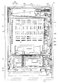
以下、パチンコ遊技機(以下、単に「パチンコ機」という)の一実施形態を、図面に基づいて詳細に説明する。図3等に示すように、パチンコ機10は、当該パチンコ機10の外郭を構成する固定枠としての外枠11を備えており、この外枠11の一側部に遊技盤取付枠としての内枠12が開閉可能に支持されている。尚、図3では便宜上、遊技盤30面上に配設される遊技部材(釘や役物等)、前枠としての前面枠セット14に取付けられるガラスユニット137等を省略して示している。
(First embodiment)
Hereinafter, an embodiment of a pachinko gaming machine (hereinafter, simply referred to as "pachinko machine") will be described in detail with reference to the drawings. As shown in FIG. 3 and the like, the
外枠11は、図6等に示すように、上辺枠構成部11a及び下辺枠構成部11bが木製の板材により構成され、左辺枠構成部11c及び右辺枠構成部11dがアルミニウム合金製の押出成形材により構成され、これら各枠構成部11a〜11dがネジ等の離脱可能な締結具により全体として矩形枠状に組み付けられている。
As shown in FIG. 6 and the like, the
左辺枠構成部11cの上下端部には、それぞれ上ヒンジ81及び下ヒンジ82が取着されている(図1参照)。当該上ヒンジ81及び下ヒンジ82にて、内枠12の上下部が回動可能に支持されており、これにより内枠12が開閉可能となる。そして、外枠11の内側に形成される空間部に内枠12等が収容される。
An
また、右辺枠構成部11dには、その幅方向後端部近傍から外枠11内側へ向け突出した延出壁部83が形成されている。延出壁部83は、内枠12の右側部背面側に設けられる施錠装置600(図6参照)に対応する上下区間全域を内枠12の背面側から覆っている(図5参照)。加えて、図3に示すように、延出壁部83の前面側には、施錠装置600の係止部材が係止される上下一対の受部84,85が設けられている。また、下側の受部85には、後述する内枠開放検知スイッチ92に当接する押圧部86が、外枠11内側に向けて突設されている。
Further, the right side
さらに、下辺枠構成部11bには樹脂製の幕板飾り87が取着されている。幕板飾り87の上面奥部には、上方に突出するリブ88が一体形成されている。これにより内枠12との間に隙間が形成されにくくなっている。
Further, a resin
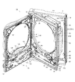
図3に示すように、内枠12の開閉軸線は、パチンコ機10の正面からみて左側において上下に沿って設定されており、この開閉軸線を軸心として内枠12が前方側に開放できるようになっている。内枠12は、外形が矩形状をなす樹脂ベース38を主体に構成されており、当該樹脂ベース38の中央部には略楕円形状の窓孔39が形成されている。
As shown in FIG. 3, the opening/closing axis of the
また、内枠12の前面側には前面枠セット14が開閉可能に取付けられている。前面枠セット14は、内枠12と同様に、パチンコ機10の正面から見て左側において上下に沿って設定された開閉軸線を軸心として前方側に開放できるようになっている。尚、前面枠セット14は、内枠12を介してではなく、外枠11に直接開放可能に支持されるように構成してもよい。
A front frame set 14 is attached to the front side of the
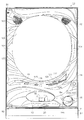
前面枠セット14は、内枠12と同様に外形が矩形状をなし、閉鎖状態においては内枠12の前面側ほぼ全域を覆う。前面枠セット14の中央部には略楕円形状の窓部101が形成されている。これにより、前面枠セット14の窓部101及び内枠12の窓孔39を介して、内枠12の後面に装着される遊技盤30(遊技領域)を外部から視認可能となる。遊技盤30の詳細な構成については後述する。
Like the
図1、図2に示すように、前面枠セット14の前面側には、その下部中央において下皿15が設けられており、下払出口16から払出された遊技球が下皿15内に貯留可能になっている。また、下皿15の手前側には、下皿15内から遊技球を排出するための球抜きレバー25が設けられている。
As shown in FIGS. 1 and 2, on the front side of the front frame set 14, a
下皿15の右方には、手前側に突出した操作手段(発射操作手段)としての遊技球発射ハンドル(以下「ハンドル18」と称する)が設けられている。尚、ハンドル18には、回動可能に設けられた回転操作体18aが設けられるとともに、図示されない位置において、ハンドル18に人手が触れたことを検知可能なタッチセンサや、ハンドル18の操作部の操作量を検知するための可変抵抗器が設けられている。そして、ハンドル18が右回りに回動操作されると、回動操作量に応じた強さで、発射装置60によって遊技球が発射される。また、ハンドル18には、ハンドル18を握った右手の親指で押圧操作可能なストップレバー18bが設けられている。当該ストップレバー18bを押圧した状態においては、ハンドル18を握っていたとしても、発射装置60による遊技球の発射が禁止される。このため、遊技球の発射を禁止しつつハンドル18の回動操作を行ったり、ハンドル18を握った状態で、一時的に遊技球の発射を止めたりすることができる。
On the right side of the
図2に示すように、下皿15の上方には、上払出口17から払出された遊技球を貯留可能な上皿19が設けられている。また、上皿19は、当該上皿19に(一旦)貯留された遊技球を一列に整列させながら後述する発射手段としての発射装置60の方へ案内するようになっている。尚、上皿19が遊技球で満杯になった状態では、払出される遊技球は、後述する下皿連通路71及び下払出口16を介して、下皿15へと案内される。
As shown in FIG. 2, above the
上皿19上面には、貸出スイッチ121と、返却スイッチ122と、残高表示部124とが設けられている。遊技ホール等において、パチンコ機10の(左)側方に配置されるCRユニットに対して残高のある遊技カードが投入(挿入)された状態で貸出スイッチ121が操作されると、その操作に応じて貸出球が上皿19に供給される。一方、返却スイッチ122は、CRユニットに挿入されたカード等の返却を求める際に操作される。また、残高表示部124では、CRユニットに挿入されているカードの残高がいくらあるのかが表示される。
A
さらに、上皿19の上面には、球抜きボタン123が設けられている。球抜きボタン123は、上皿19の上面から出没可能に構成され、図示しない付勢手段によって常には上皿19の上面から上方に突出する側へと付勢されている。球抜きボタン123が押圧操作されることで、上皿19と下皿15との間が開通し、上皿19に貯留されていた遊技球が下皿15へと案内されるようになっている。つまり、遊技者は、球抜きボタン123を操作することで、上皿19にある遊技球をいつでも下皿15に移すことができる。
Further, a
加えて、上皿19上面には、操作手段、演出操作手段としての演出ボタン125及び十字ボタン126が設けられている。演出ボタン125には発光色を適宜変更可能なLEDが内蔵されているとともに、演出ボタン125や十字ボタン126を押圧操作することで、後述する装飾図柄表示装置42における表示を切替えたり、所定の選択事項の決定を行ったりする。
In addition, on the upper surface of the
また、前面枠セット14の前面にはその周囲に各種ランプ等の発光手段が設けられている。これら発光手段は、遊技状態の変化等に応じて発光態様が変更制御され遊技中の演出効果を高める役割を果たすものである。例えば、窓部101の周縁には、LED等の発光手段を内蔵した環状電飾部102が設けられている。また、該環状電飾部102の両側部には、所定のエラー時に点灯するエラー表示ランプ104が設けられている。尚、環状電飾部102のうち各エラー表示ランプ104の上方部位には、前面枠セット14の背面に設けられるスピーカSP(図3参照)に対応して細かな透孔が多数形成されている。
Further, a light emitting means such as various lamps is provided around the front surface of the front frame set 14. These light emitting means play a role of enhancing the effect during the game by changing and controlling the light emitting mode according to the change of the game state. For example, on the periphery of the
前面枠セット14の背面側にはガラスユニット137が取付けられている。ガラスユニット137は、従来の前後一対の矩形状の板ガラスが前後対をなして別々に取着されるものではなく、全体として丸形をなし、アッセンブリ化された上で取付けられている。
A
次に、内枠12について図4を参照して説明する。上述した通り、内枠12には、窓孔39の後側において、遊技盤30が樹脂ベース38の裏側に当接した状態で装着されている。従って、遊技盤30前面の略中央部分が窓孔39を通じて内枠12の前面側に露出した状態となっている。
Next, the
また、内枠12(樹脂ベース38)の前面下部、すなわち窓孔39の下方位置には、発射装置60及び当該発射装置60によって発射された直後の遊技球を案内する発射レール61が取付けられている。本実施形態では、発射装置60としてソレノイド式発射装置を採用している。さらに、発射装置60の上方には、上皿19から案内される遊技球を、内蔵された駆動手段(例えばソレノイド)の駆動により、1球ずつ発射装置60の発射位置へと案内する球送り装置63が設けられている。
In addition, a lower portion of the front surface of the inner frame 12 (resin base 38), that is, a position below the
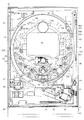
次に、遊技盤30の構成について図4を参照して説明する。遊技盤30には、一般入賞装置31、可変入球手段としての可変入賞装置32、始動入球手段、特定手段としての第1始動入賞装置33a及び第2始動入賞装置33b、スルーゲート34、可変表示装置ユニット35等が配設されている。周知の通り、発射装置60により発射された遊技球は、遊技盤30の前面側、すなわち、遊技盤30と、ガラスユニット137との間に形成される遊技領域に案内され、当該遊技球が、一般入賞装置31、可変入賞装置32、始動入賞装置33a、33b等の各種入賞口に入球(入賞)すると、各種検知スイッチにより検知され、各種入賞口に対応する数の賞球が上皿19又は下皿15へ払い出される。
Next, the configuration of the
本実施形態では、始動入賞装置33a、33bへの入球があった場合には3個、一般入賞装置31への入球があった場合には10個、可変入賞装置32への入球があった場合には15個の遊技球が払出されるように構成されている。また、遊技球が通過するだけの(遊技盤30の裏面側に排出されることのない)スルーゲート34に遊技球が通過しても、遊技球の払出しは行われない。加えて、第1始動入賞装置33a、一般入賞装置31、及び、スルーゲート34には、遊技領域を移動する遊技球が常に入球可能(通過可能)に構成されているのに対し、第2始動入賞装置33b、及び、可変入賞装置32に関しては、遊技球が入球可能な開状態と、入球不可能な閉状態とに状態変化するように構成されている。
In the present embodiment, three balls are entered in the
その他に、遊技盤30には、遊技領域の最下部に対応してアウト口36が設けられており、一般入賞装置31等の各種入賞口に入賞しなかった遊技球は、このアウト口36を通って遊技領域外へと排出される。また、遊技盤30には、遊技球の落下方向を適宜分散、調整等するために多数の釘(遊技釘)が植設されているとともに、風車等の各種部材(役物)が配設されている。
In addition, the
また、本実施形態の遊技盤30は、アクリル樹脂又はポリカーボネート等の透明な樹脂により構成されている。さらに、遊技盤30の前面や後面に対して直接プリントが行われたり(シールが貼着されたり)、遊技盤30の後方に装飾用の役物が設置されたりする等して、窓孔39の内周側(遊技盤30の視認範囲)における装飾等が行われている。
In addition, the
遊技領域の略中央部には、可変表示装置ユニット35が配設されている。可変表示装置ユニット35は、詳しくは後述する装飾図柄表示装置42と、装飾図柄表示装置42を囲むようにして設けられたセンターフレーム47とを備え、センターフレーム47の内周側には、遊技球が進入しないように構成されている。
The variable
可変表示装置ユニット35の下方位置には、第1始動入賞装置33aが設けられている。第1始動入賞装置33aは、遊技盤30の前面部から前方へ突出し、その上側に遊技球が常時入賞可能な入賞口(始動入賞口)が開口している。尚、本実施形態の第1始動入賞装置33aには、第1始動入賞装置33aへの遊技球の入球し易さを変化させるような開閉部材は設けられていない。
A first
第1始動入賞装置33aの下方位置には、第2始動入賞装置33bが配設されている。第2始動入賞装置33bは、遊技球が入球可能な第2始動入賞装置33bの入賞口(始動入賞口)の左右両側に隣接して、回動変位可能に設けられた一対の羽根部材37を備えている。本実施形態では、羽根部材37が上下に延びる閉位置とされている場合には、当該羽根部材37の先端部と、第1始動入賞装置33aとの間に遊技球が通過する余地がなく、第2始動入賞装置33bは、遊技球を入球させることが不可能な閉状態となっている。一方、羽根部材37が外側に開く開位置に変化することで、羽根部材37と第1始動入賞装置33aとの間に遊技球が通過する隙間が確保され、第2始動入賞装置33bは、遊技球の入球が許容されるとともに、羽根部材37によって第2始動入賞装置33bの側方を移動する遊技球が第2始動入賞装置33bの始動入賞口へと案内される開状態となる。
A second
尚、詳しくは後述するが、第1始動入賞装置33a、第2始動入賞装置33bには、それぞれ入賞した遊技球を検知する条件成立検知手段、始動入球検知手段、特定検知手段としての第1始動入賞スイッチ224a、第2始動入賞スイッチ224bが設けられている。当該始動入賞スイッチ224a、224bにて遊技球が検知された場合には、可変入賞装置32が開放される特別遊技状態としての大当たり状態を発生させるか否かの当否抽選等が行われるとともに、後述する特別表示装置43a、43b、及び、装飾図柄表示装置42にて変動表示が行われる構成となっている。そして、当否抽選にて当選した場合には、大当たり状態が付与されることとなる。
As will be described later in detail, the first
第2始動入賞装置33bの下方位置には、可変入賞装置32が設けられている。可変入賞装置32は、遊技盤30の後方へと通じる大入賞口と、大入賞口を開閉するシャッタと、シャッタを動作させるための大入賞口ソレノイドと、大入賞口に入球した遊技球を検知するカウントスイッチ223とを備え、大入賞口ソレノイドを駆動制御し、シャッタを開閉させることで、可変入賞装置32(大入賞口)を閉状態と開状態とに切替えている。
The
可変入賞装置32は、通常は遊技球が入球できない閉状態になっており、大当たり状態の際に、遊技球が入賞可能な開状態とされる。尚、本実施形態の可変入賞装置32の大入賞シャッタは、大入賞口の下縁部に沿って大入賞シャッタの下縁部が回動可能に軸支されており、可変入賞装置32の閉状態では、大入賞シャッタが上下に延びて大入賞口を閉塞し、大入賞シャッタの前方を遊技球が通過可能な状態となる。一方、可変入賞装置32の開状態では、大入賞シャッタが前方に回動して前後に延び(上面が後方に向けて少し下方傾斜している)、大入賞口の前方に流下してきた遊技球を大入賞シャッタの裏面(上面)で受けて大入賞口へと案内するようになっている。
The
遊技領域のうち(遊技盤30を遊技機10の前方から見て)可変表示装置ユニット35の左側方に位置する領域(以下、「左側方領域」と称する)、及び、可変表示装置ユニット35の右側方に位置する領域(以下、「右側方領域」と称する)には、スルーゲート34が配置されている。スルーゲート34は、遊技領域を流下する遊技球が1球ずつ通過可能に構成されている。詳しくは後述するが、スルーゲート34は、当該スルーゲート34を通過する遊技球を検知可能なスルーゲートスイッチ225を備えている。
Of the game area (when the
また、スルーゲートスイッチ225にて遊技球が検知された場合に、第2始動入賞装置33bを開状態とするか否かの入球サポート抽選(開放抽選)が行われるとともに、普通図柄表示装置41にて当該入球サポート抽選の結果を教示するための変動表示が行われる。そして、入球サポート抽選にて当選した場合には、当該変動表示の終了後に第2始動入賞装置33bが規定時間だけ開状態とされる。
In addition, when a game ball is detected by the through
本実施形態では、当否抽選にて所定の確率で大当たりに当選する「低確率状態」と、当否抽選にて低確率状態よりも高確率で大当たりに当選する「高確率状態」とがある。さらに、第2始動入賞装置33bの羽根部材37が比較的頻繁に開放され、遊技球を第2始動入賞装置33cへ入球させ易くなる第2入球状態としての「高入球状態」と、高入球状態よりも羽根部材37が開放される時間帯が減少する第1入球状態としての「低入球状態」とがある。以下、低確率状態かつ低入球状態である状態を「通常モード」と称し、低確率状態かつ高入球状態である状態を「時間短縮モード」と称し、高確率状態かつ高入球状態である状態を「確変モード」と称する。尚、高確率状態かつ低入球状態である状態(潜確モード)を設定するように構成してもよい。
In the present embodiment, there are a "low probability state" in which the jackpot is won with a predetermined probability in the win/loss lottery, and a "high probability state" in which the jackpot is won with a higher probability than the low probability state in the win/loss lottery. Further, the
尚、高入球状態としては、例えば、(1)普通図柄表示装置41における変動表示時間が低入球状態時よりも短い状態、(2)第2始動入賞装置33bの一回の開放時間(規定時間)が低入球状態時に比べて長い状態、(3)第2始動入賞装置33bの一回の開放につき入球可能となる遊技球の規定個数が低入球状態時に比べて多い状態、(4)入球サポート抽選の当選一回当たりの第2始動入賞装置33bの開放回数が低入球状態時に比べて多い状態、(5)入球サポート抽選の当選確率が低入球状態時よりも高い状態とすることなどが挙げられる。本実施形態における高入球状態は、上記(1)、(2)、(4)、(5)の構成を採用している。勿論、これに限らず、「高入球状態」として、構成(1)〜(5)のいずれか1つ、又は、これら構成(1)〜(5)の任意の組合せを採用してもよい。これにより、第2始動入賞装置33bに対し遊技球が頻繁に入賞しやすくなり、当否抽選の実行される回数が増えると共に、遊技者の持ち球の減少が抑制される球持ちのよい状態となる。
In addition, as the high-ball entry state, for example, (1) a state in which the fluctuation display time in the normal
さらに、本実施形態では、通常モード、及び、確変モードは、大当たり状態が発生するまで継続されるのに対し、時間短縮モードは大当たり状態が発生しなくても特別表示装置43a、43b及び装飾図柄表示装置42における変動表示が予め設定された規定回数(本例では、100回)行われると終了し、通常モードに移行する構成となっている。
Further, in the present embodiment, the normal mode and the probability variation mode are continued until the big hit state occurs, whereas the time reduction mode does not require the big hit state, the
また、本実施形態の大当たり種別としては、10ラウンド確変大当たり(以下「10RS」と言う)と、10ラウンド通常大当たり(以下「10RN」と言う)と、4ラウンド確変大当たり(以下「4RS」と言う)とがある。可変入賞装置32が30秒間開放されること、又は、可変入賞装置32が開放されてから可変入賞装置32に10個の遊技球が入球することを1ラウンドとして、「10RS」、「10RN」に関しては、それが10回繰り返され、「4RS」に関しては、それが4回繰り返されてから、大当たり状態が終了する。加えて、「10RS」、「4RS」の大当たり状態終了後には「確変モード」が付与され、「10RN」の大当たり状態終了後には「時間短縮モード」(本例では、変動表示100回分)が付与される。
Further, as the jackpot types of the present embodiment, 10 round certainty variation jackpots (hereinafter referred to as “10RS”), 10 round regular jackpots (hereinafter referred to as “10RN”), and four rounds probability variation jackpots (hereinafter referred to as “4RS”). ) There is. The
さらに、本実施形態では、第2始動入賞装置33bへの入球に基づく当否抽選において、「小当たり」に当選する場合がある。第2始動入賞装置33bへの入球に基づく当否抽選において、小当たりした場合には、小当たり状態として、可変入賞装置32が1.8秒間(1回)開放される。尚、小当たり状態が発生する前と、発生した後とで遊技モードが変化することはない。
Further, in the present embodiment, there may be a case where the "small hit" is won in the win/loss lottery based on the entry into the second
また、略楕円形状の遊技領域の右上部に隣接して、第1始動入賞装置33aへの遊技球の入球を契機として行われる当否抽選の結果を教示するための変動表示が行われる特別表示手段、可変表示手段としての第1特別表示装置43aと、第2始動入賞装置33bへの遊技球の入球を契機として行われる当否抽選の結果を教示するための変動表示が行われる特別表示手段、可変表示手段としての第2特別表示装置43bと、特別表示装置43a、43bにおける変動表示中に始動入賞装置33a、33bへの遊技球の入球があった場合に、当該入球に対応する変動表示を保留記憶したことを示す保留表示手段としての第1保留表示装置46a及び第2保留表示装置46bと、スルーゲート34への遊技球の通過に基づいて行われる入球サポート抽選の結果を教示するための変動表示が行われる普通表示手段としての普通図柄表示装置41と、普通図柄表示装置41における変動表示中にスルーゲート34への遊技球の通過があった場合に、当該通過に対応する変動表示を保留記憶したことを示す普通保留表示装置44とが、パチンコ機10の前方から視認可能に設けられている。本実施形態では、第1特別表示装置43a、第2特別表示装置43b、第1保留表示装置46a、第2保留表示装置46b、普通図柄表示装置41、及び、普通保留表示装置44は、後述する主制御手段としての主制御装置261により直接的に表示制御される。
In addition, adjacent to the upper right portion of the substantially oval game area, a variable display for teaching the result of the winning/winning lottery that is triggered by the entry of the game ball into the first
第1特別表示装置43aは、4個のLED(第1特図ランプ)により構成されている。そして、第1始動入賞装置33aへの遊技球の入球を契機として、第1特別表示装置43aにて第1特図ランプの切替表示(変動表示)が行われる構成となっている。
The first special display device 43a includes four LEDs (first special figure lamp). Then, triggered by the entry of the game ball into the first
第2特別表示装置43bは、4個のLED(第2特図ランプ)により構成されている。そして、第2始動入賞装置33bへの遊技球の入球を契機として第2特別表示装置43bにて第2特図ランプの切替表示(変動表示)が行われる構成となっている。
The second
また、第1特別表示装置43a及び第2特別表示装置43bにて変動表示が所定時間行われた後、当否抽選の結果に基づいて、変動表示が停止されることとなる。つまり、変動表示が停止したときの点灯態様(点灯している特図ランプの組合わせ)と、当否抽選の各種結果とが対応付けられており、変動表示が停止したときの点灯態様により、当否抽選の結果、すなわち、「大当たり」、「小当たり」、又は、「外れ」であることが確定的に表示されるようになっている。
Further, after the variable display is performed for a predetermined time on the first special display device 43a and the second
さらに、第1特別表示装置43a、及び、第2特別表示装置43bにおいては、停止させる点灯態様(停止態様)によって、大当たり種別、すなわち、「10RS」、「10RN」、及び、「4RS」のうちいずれであるかについても教示される。また、各種大当たり種別や、小当たりや、外れであることをそれぞれ教示する第1特別表示装置43a及び第2特別表示装置43bの停止態様は1つではなく複数存在し、それらのいずれかが選択されて停止表示される。
Further, in the first special display device 43a and the second
尚、本実施形態では、第1始動入賞装置33aへの遊技球の入球を契機として行われる当否抽選では、「小当たり」に当選する可能性はないが、当選する可能性があるように構成してもよい。さらに、第2始動入賞装置33bへの遊技球の入球を契機として行われる当否抽選では「小当たり」に当選する可能性が無いように構成することも可能である。
In the present embodiment, there is no possibility of winning the “small hit” in the win/loss lottery, which is carried out when the game ball is entered into the first
また、第1特別表示装置43a及び第2特別表示装置43bにおける停止表示は規定時間維持されるように構成されており、規定時間経過後(変動インターバル後)に次の変動表示を開始可能に構成されている。さらに、第1特別表示装置43a又は第2特別表示装置43bにおける停止表示後、規定時間が経過しても、次の変動表示が行われない場合には、当該第1特別表示装置43a又は第2特別表示装置43bにおいて、当否抽選の結果を示す点灯態様から、変動表示が行われていない待機状態であることを示す点灯態様へと切替えられるように構成されている。尚、当否抽選の結果を示す点灯態様がそのまま維持される構成としてもよい。
Further, the stop display on the first special display device 43a and the second
第1保留表示装置46a及び第2保留表示装置46bは、それぞれ2個のLED(第1保留ランプ、第2保留ランプ)によって構成されている。本実施形態では、第1始動入賞装置33aへの遊技球の入球に基づく変動表示(以下、「第1変動表示」と称する)を4回分まで保留記憶可能に構成されている。さらに、第2始動入賞装置33bへの遊技球の入球に基づく変動表示(以下、「第2変動表示」と称する)についても4回分まで保留記憶可能に構成されている。
Each of the first hold display device 46a and the second hold display device 46b includes two LEDs (first hold lamp, second hold lamp). In the present embodiment, variable display (hereinafter, referred to as "first variable display") based on the entry of the game ball into the first start winning a
また、例えば、第1変動表示が1回分保留されている場合には、左側(遊技領域内周側)の第1保留ランプが点灯し、第1変動表示が2回分保留されている場合には、左右の第1保留ランプが点灯し、第1変動表示が3回分保留されている場合には、左側の第1保留ランプが点滅するとともに、右側の第1保留ランプが点灯し、第1変動表示が4回分保留されている場合には、左右の第1保留ランプが点滅する。尚、大当たり状態中に新たに遊技球が始動入賞装置33a、33bに入賞した場合、その分の変動表示についても保留される。
Further, for example, when the first fluctuation display is held once, the first holding lamp on the left side (inside of the game area) is turned on, and when the first fluctuation display is held twice , When the first hold lamps on the left and right are turned on and the first variation display is held for three times, the first hold lamp on the left blinks and the first hold lamp on the right turns on, and the first variation When the display is held for four times, the left and right first holding lamps blink. In addition, when the game ball newly wins the
本実施形態では、保留された変動表示は、基本的に、保留された順番で消化されるのであるが、第1変動表示及び第2変動表示の両方が保留されている場合には、第2変動表示が優先的に消化されるようになっている。すなわち、第2始動入賞装置33bへの入賞を契機とする第2変動表示が全て消化された状態でなければ、第1始動入賞装置33aへの入球を契機とする第1変動表示が行われない構成となっている。例えば、第1保留ランプが1つ点灯している状態において、第2始動入賞装置33bに遊技球が入球し、第2保留ランプが1つ点灯した場合、第1変動表示が後回しにされ、先に第2変動表示が行われることとなる。但し、第1変動表示の変動中に第2変動表示が保留記憶された場合には、変動中の第1変動表示の後に、第2変動表示が行われる。
In this embodiment, the suspended variable displays are basically consumed in the suspended order, but when both the first variable display and the second variable display are suspended, the second variable display is suspended. The variable display is preferentially digested. That is, if the second variation display triggered by the winning of the second
普通図柄表示装置41は、2個のLED(普図ランプ)により構成されている。そして、普通図柄表示装置41では、スルーゲート34への遊技球の通過を契機として、例えば、右側(遊技領域外周側)の普図ランプが点滅表示される(変動表示される)構成となっている。また、普通図柄表示装置41にて変動表示が所定時間行われた後、入球サポート抽選の結果に基づいて、変動表示を停止させる。つまり、変動表示が停止したときの点灯態様(点灯している普図ランプの組合わせ)と、入球サポート抽選の各種結果とが対応付けられており、変動表示が停止したときの点灯態様により、入球サポート抽選の結果が確定的に表示される。例えば、左右の普図ランプを両方とも点灯させることで「当選」を示し、左側の普図ランプのみを点灯させることで「外れ」を示す。
The normal
普通保留表示装置44は、2個のLED(普通保留ランプ)により構成されている。本実施形態では、スルーゲート34への遊技球の通過に基づいて行われる普通図柄表示装置41の変動表示を4回分まで保留記憶可能に構成されている。例えば、普通図柄表示装置41の変動表示が1回分保留されている場合には、左側(遊技領域内周側)の普通保留ランプが点灯し、2回分保留されている場合には、左右の普通保留ランプが点灯し、3回分保留されている場合には、左側の普通保留ランプが点滅するとともに、右側の普通保留ランプが点灯し、4回分保留されている場合には、左右の普通保留ランプが点滅する。尚、大当たり状態中に新たに遊技球がスルーゲート34を通過した場合、その分の変動表示についても保留される。
The normal
また、可変表示装置ユニット35には、液晶表示装置によって構成され、装飾図柄を表示可能な演出表示手段、可変表示手段としての装飾図柄表示装置42が設けられている。装飾図柄表示装置42は、第1特別表示装置43a及び第2特別表示装置43bによる変動表示に合わせて装飾図柄を変動表示させるように構成されている。さらに、装飾図柄表示装置42は、後述するサブ制御装置262及び表示制御装置45によって表示内容が制御される。すなわち、装飾図柄表示装置42においては、第1特別表示装置43a及び第2特別表示装置43bにて表示される結果に対応させるように、主制御装置261からのコマンドに基づき、サブ制御装置262によって補助的な表示内容が決定され、当該決定に基づき、表示制御装置45によって表示が行われる。
Further, the variable
装飾図柄表示装置42には、例えば、上、中、下の3つの図柄表示領域(上図柄表示領域、中図柄表示領域、下図柄表示領域)が設けられ、各図柄表示領域において複数種類の装飾図柄(例えば1〜9の数字が付された数字図柄)が順次表示され(変動表示され)、その後、図柄表示領域毎に順番に(例えば、上図柄表示領域→下図柄表示領域→中図柄表示領域の順に)装飾図柄が停止表示されるようになっている。例えば、主制御装置261にて大当たり状態の発生が確定すると、第1又は第2特別表示装置43a、43bにて大当たりに対応する表示がなされるとともに、装飾図柄表示装置42にて装飾図柄が大当たりに対応する組合わせで停止表示され(例えば、上図柄表示領域、中図柄表示領域、及び下図柄表示領域において所定の有効ライン上に同一の装飾図柄が並ぶようにして停止表示され)、大当たり状態が開始される。
The decorative
また、装飾図柄が大当たりに対応する組合わせで停止表示される場合には、その前段階として、例えば、上図柄表示領域及び下図柄表示領域において同一の装飾図柄が所定の有効ライン上に停止表示されることとなる。このように上図柄表示領域及び下図柄表示領域にて所定の有効ライン上に同一図柄が停止表示されるとともに、中図柄表示領域において未だ変動表示が行われている状態が「リーチ状態」である。勿論、リーチ状態が発生したからといって必ずしも大当たりとなるわけではなく、外れる場合もある。 Further, when the decorative design is stopped and displayed in a combination corresponding to the jackpot, as the previous stage, for example, the same decorative design is stopped and displayed on a predetermined effective line in the upper design display region and the lower design display region. Will be done. In this way, the same symbol is stopped and displayed on the predetermined effective line in the upper symbol display area and the lower symbol display area, and the state where the variable display is still being performed in the middle symbol display area is the "reach state". .. Of course, just because a reach state has occurred does not necessarily mean a big hit, and there is also a case where it goes off.
本実施形態では、リーチ状態が発生した後、中図柄表示領域において、上図柄表示領域及び下図柄表示領域において停止表示された装飾図柄(リーチ図柄)と同じ装飾図柄が同じ有効ライン上に停止表示された場合(ゾロ目が停止表示された場合)に、大当たり状態が付与される。また、奇数のゾロ目の場合には、「10RS」、又は、「4RS」のどちらかが発生し、偶数のゾロ目の場合には、「10RS」、「4RS」、又は、「10RN」のいずれかが発生する。 In the present embodiment, after the reach state occurs, in the middle symbol display area, the same decorative symbol as the decorative symbol (reach symbol) stopped and displayed in the upper symbol display region and the lower symbol display region is stopped and displayed on the same effective line. When it is performed (when the doublet is stopped and displayed), the jackpot state is given. Further, in the case of an odd-numbered doublet, either "10RS" or "4RS" occurs, and in the case of an even-numbered doublet, "10RS", "4RS", or "10RN" is generated. Either happens.
また、ゾロ目以外の装飾図柄の組合わせは基本的に「外れ」を教示するものであるが、「小当たり」となる場合には、ゾロ目ではなく、装飾図柄が有効ライン上において特定の組合わせ(チャンス図柄の組合わせ、所謂チャンス目)で停止表示されるようになっている。本実施形態では、例えば、上・中・下図柄表示領域で「3」・「4」・「1」が停止表示される態様がチャンス図柄の組合わせである。 Also, the combination of decorative patterns other than the doublet basically teaches "out", but when it is "small hit", the decorative pattern is not a doublet, but a specific pattern on the activated line. It is designed to be stopped and displayed in combination (combination of chance patterns, so-called chance). In the present embodiment, for example, a mode in which “3”, “4”, and “1” are stopped and displayed in the upper, middle, and lower symbol display areas is a combination of chance symbols.
尚、本実施形態では、滞在している遊技モードを教示又は示唆する演出として、装飾図柄表示装置42において(背景等が異なる)複数の演出ステージが用意されている。より具体的には、確変モードに滞在していることが確定する「確変ステージ」と、通常モードに滞在していることが確定する「通常ステージ」と、時間短縮モード又は確変モードのどちらかに滞在している「引き戻しステージ」とがある。つまり、「4RS」に当選した場合には、その大当たり状態終了後に「確変ステージ」に移行する。また、「10RN」に当選した場合には、その大当たり状態終了後に「引き戻しステージ」に移行し、さらに、引き戻しステージにおいて変動表示が100回行われた場合には、「通常ステージ」に移行する。加えて、「10RS」に当選した場合には、その大当たり終了後に、「確変ステージ」又は「引き戻しステージ」のどちらかに移行する。
In the present embodiment, a plurality of effect stages (different backgrounds, etc.) are prepared in the decorative
つまり、確変モードにおいて、「10RN」に当選すると、時間短縮モードを挟んで、通常モードに移行してしまう。この点、確変モードにおいて「10RS」に当選した時にも、装飾図柄表示装置42等において、「10RN」の場合と同様の演出が導出され得るように(例えば、確変モードで「10RS」に当選した場合の1/15の確率で、確変モードが付与される教示が行われず、かつ、確変モードであることの教示も行われない場合があるように)構成することで、引き戻しステージに移行したとしても、実は確変モードであるのではないかという期待を持たせることができる。
In other words, if "10RN" is won in the probability variation mode, the time reduction mode is sandwiched and the mode shifts to the normal mode. In this respect, even when "10RS" is won in the probability variation mode, the same effect as in the case of "10RN" can be derived in the decorative
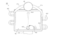
また、本実施形態では、始動入賞装置33a、33bへの遊技球の入球に基づいて行われる変動表示が保留されていること(変動表示を実行させる権利を得ていること)が、装飾図柄表示装置42においても教示されるようになっている。図43に示すように、装飾図柄表示装置42の右下部には、変動表示が保留記憶されていることを示す保留アイコン461を表示する保留表示エリア462が設けられている。本実施形態の保留アイコン461は、「遊技球」を模した図形となっている。保留表示エリア462は、保留情報記憶エリア(第1及び第2保留情報記憶エリア)の保留エリアに記憶された保留情報に対応して、最大で4つの保留アイコン461を表示可能となっている。保留アイコン461は横並びで表示され、左側に位置する保留アイコン461が、先に消化される変動表示に対応している。
Further, in the present embodiment, the variable display performed based on the entry of the game balls into the
尚、本実施形態では、保留情報記憶エリアの実行エリアに記憶された保留情報に対応する保留アイコン461は、保留表示エリア462には表示されない。また、第1変動表示、及び、第2変動表示を合わせて5つ以上の保留記憶がある場合であっても、保留表示エリア462に表示される保留アイコン461は4つである。
In this embodiment, the
さらに、本実施形態では、第1変動表示に対応する保留アイコン461と、第2変動表示に対応する保留アイコン461とが共通の態様となっており、保留アイコン461を視認するだけでは、第1変動表示及び第2変動表示のどちらに対応する保留アイコン461であるかを識別不可能となっている。また、保留アイコン461は、保留情報記憶エリアの記憶エリアに記憶された情報に基づいて、対応する変動表示の大当たり期待度を示唆する態様で導出される場合がある。かかる態様の保留アイコン461は複数種類用意されており、保留アイコン461のパターン(種類)と、大当たり状態発生への当選期待度(大当たり期待度)とが対応付けられている。本実施形態では、保留アイコン461として、デフォルトとなる銀色(灰色)の球の他、青色、赤色の球を表示可能であり、基本的に銀色(灰色)→青色→赤色の順に、大当たり期待度が高められるようになっている。加えて、保留アイコン461が導出されてから、当該保留アイコン461に対応する変動表示が消化されるまでの間に、保留アイコン461のパターンが変化する(保留変化演出が導出される)場合がある。
Further, in the present embodiment, the
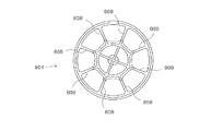
さて、図4に示すように、本実施形態の可変表示装置ユニット35は、センターフレーム47の上辺部中央位置に設けられ、液晶表示装置によって構成されるサブ表示装置48と、装飾図柄表示装置42の後面側から側方、及び、下方に突出するようにして設けられた移動式役物演出手段、引き継ぎ演出手段(疑似球演出手段)としての疑似球演出装置49とを備えている。
Now, as shown in FIG. 4, the variable
本実施形態のサブ表示装置48は、表示部が正面視略円形をなしている。また、サブ表示装置48の両側方には、可変表示装置ユニット35(センターフレーム47)の上辺部に沿って延在し、LEDが内蔵された左右一対の発光演出部47aが設けられている。各発光演出部47aの内部には、発光演出部47aの延在方向(センターフレーム47の上辺部)に沿って複数のLEDが並べて設置されており、個別に点灯制御可能に構成されている。本実施形態では、パチンコ機10の前方から視認した場合に、サブ表示装置48と、装飾図柄表示装置42の表示部とが上下に近接配置されている。さらに、各発光演出部47aは、サブ表示装置48と連結されている上、可変表示装置ユニット35(センターフレーム47)の両側辺部(又はその近傍部位)にまで延在している。
In the
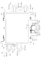
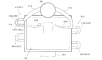
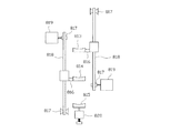
さて、図4、図39〜図42に示すように、疑似球演出装置49は、左ユニット401と、右ユニット402と、下ユニット403とを備えている。左ユニット401、右ユニット402、及び、下ユニット403は、それぞれ移動式役物としての疑似球FB(図39等参照)が力学的エネルギーに基づいて移動可能に構成される移動式役物移動領域404(疑似球移動領域)を備えている。そして、当該移動式役物移動領域404を移動する疑似球FBの挙動により所定の(例えば、大当たりか否かの)示唆又は教示を行う移動式役物演出手段としての「疑似球演出」を行うようになっている。また、疑似球FB(直径)は、遊技球よりも若干(例えば、1mm程度)大きく構成され、比較的見易くなっている。尚、疑似球FBの色(膨張色、収縮色)に応じて、疑似球FBの大きさを変更してもよい。
Now, as shown in FIG. 4 and FIGS. 39 to 42, the pseudo
尚、左ユニット401、及び、右ユニット402は、基本的に同じ構成となっている(向かい合わせて上下反対向きに配置し、一部の部材(後述する始動ソレノイド413)の取付け位置を変更したものであって、使用されている部品は同じである)。また、本実施形態では、左ユニット401、右ユニット402、及び、下ユニット403をそれぞれ遊技盤30の後面側に取付ける構成(個別に取着自在)となっているが、左ユニット401、右ユニット402、及び、下ユニット403を取付可能な取付板が設けられ、取付板に取付けられて位置決めされた左ユニット401、右ユニット402、及び、下ユニット403をまとめて遊技盤30の後面側に取付けるような構成(取付板に対しては個別に取着自在)としてもよい。また、左ユニット401、及び、右ユニット402のそれぞれが移動式役物移動領域ユニットに相当する。
The
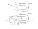
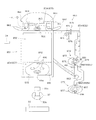
図40、図41に示すように、左ユニット401は、上下に延びる略四角筒状の本体部405と、略U字管状をなし、両端部が本体部405に連結される演出通路部材406と、本体部405の内側に収容された状態において、本体部405の長手方向に沿ってスライド可能に構成されるとともに、使用されていない疑似球FBを格納する移動式役物格納手段としての格納部材408とを備えている。
As shown in FIGS. 40 and 41, the
図39、図40に示すように、演出通路部材406は、本体部405と連結された上端部と下端部との間を疑似球FBが通過可能とする通路(以下、「連結通路406a」と称する)を備えている。また、演出通路部材406は、透明な素材により構成されるとともに、装飾図柄表示装置42、及び、センターフレーム47の側辺部よりも側方に突出して透明な遊技盤30の後方に配置されており、パチンコ機10の前方から、遊技盤30を介して、連結通路406aを移動する疑似球FBを視認可能となっている。つまり、演出通路部材406の一対の端部のうち上側に位置する端部から、下側に位置する端部までの間を移動する疑似球FBの様子を視認させることで、疑似球演出を行うこととしている。尚、本実施形態では、演出通路部材406の両端部付近は、装飾図柄表示装置42の後方に配置されており、演出通路部材406の端部に連結される本体部405等についても、装飾図柄表示装置42の後方に配置され、パチンコ機10の前方からは視認不可能(又は困難)となっている。
As shown in FIGS. 39 and 40, the
図40に示すように、本実施形態の格納部材408は、一側方側に開口するとともに、上下に長い四角箱状をなしており、内側の空間が上下に4段に分割されるようにして4つの格納部屋408を有している。各格納部屋408には、それぞれ疑似球FBを1つずつ格納可能に構成されており、本実施形態では、どの格納部屋408にどの種類の疑似球FBが格納されるかが対応付けられている。本実施形態では、一番上の格納部屋408と、上から2番目の格納部屋408とにそれぞれ銀色(灰色)の疑似球FBが収容され、上から3番目の格納部屋408に青色の疑似球FBが収容され、上から4番目(一番下)の格納部屋408に赤色の疑似球FBが収容されている。尚、一対の銀色の疑似球FBは、基本的には交互に使用されるようになっている。
As shown in FIG. 40, the
また、図41に示すように、格納部材408の側面には、上下に延在する鋸歯状部を有するラック形状部409が連結されている。図42に示すように、ラック形状部409の鋸歯状部には、ピニオン部材410が噛み合わされ、ピニオン部材410と連結(直接的、又は、間接的のどちらでも可)されているステッピングモータにより構成される疑似球演出モータ411の駆動に基づいて、上下にスライド可能に構成されている。疑似球演出モータ411は、サブ制御装置262により駆動制御される。つまり、例えば、ラック形状部409に特殊形状部を設けるとともに、特殊形状部の通過を判別可能なセンサを設けて、ラック形状部409、ひいては、格納部材408の高さ位置を把握可能とし、決定内容に応じて、格納部材408の高さ位置の調節制御を行うようになっている。尚、疑似球演出が行われていない状態や、電源立ち上げ時には、格納部材408が上限位置又は下限位置に配置され、格納部材408の位置情報の初期化が図られるようになっている。また、本実施形態では、ラック形状部409、ピニオン部材410、疑似球演出モータ411、及び、サブ制御装置262により変位手段が構成される。尚、疑似球演出モータ411の回転量等で格納部材408の位置を把握する構成としてもよい。
Further, as shown in FIG. 41, a rack-shaped
図40等に示すように、本実施形態では、1つの左ユニット401において、2つの演出通路部材406が設けられており、1つの本体部405に対して、演出通路部材406が上下一対で連結されている。これに対し、左ユニット401が備える格納部材408、及び、疑似球演出モータ411は、それぞれ1つである。本実施形態では、サブ制御装置262が、格納部材408の位置情報に基づいて、疑似球演出モータ411を駆動制御し、格納部材408の各格納部屋408の位置(高さ位置)と、各演出通路部材406の上端部位置、及び、下端部位置とを合致させることができるように構成されている。
As shown in FIG. 40 and the like, in this embodiment, one
すなわち、左ユニット401において上下一対の演出通路部材406のうち上側の演出通路部材406に青色の疑似球FBを通過させようとした場合には、上側の演出通路部材406の上側の端部の高さ位置と、格納部材408の上から3番目の格納部屋408の高さ位置とを合致させるようになっている。その一方で、疑似球演出で使用された演出通路部材406の下端部の高さ位置と、疑似球演出で使用された疑似球FBが疑似球演出に使用される前に格納されていた格納部屋408の高さ位置とを合致させることで、疑似球演出で使用された疑似球FBが元の格納部屋408に格納される。
That is, when it is attempted to pass the blue pseudo sphere FB through the upper
本実施形態では、格納部材408のうち、演出通路部材406の上端部と横並びとされた格納部屋408(の空間)、演出通路部材406の下端部と横並びとされた格納部屋408、及び、演出通路部材406の連結通路406aにより移動式役物移動領域404が構成されている。つまり、演出通路部材406の上端部と横並びとされた格納部屋408(の空間)が移動式役物移動領域404の始点に相当し、演出通路部材406の下端部と横並びとされた格納部屋408(の空間)が移動式役物移動領域404の終点に相当する。
In the present embodiment, of the
尚、格納部材408は、疑似球演出で使用された疑似球FBが格納部屋408から導出された後(後述の始点検知スイッチ415の検知に基づいて)、直ちに、対応する演出通路部材406の下端部の高さ位置と、前記疑似球FBが導出された格納部屋408の高さ位置とを合わせるようにして変位することとしてもよい。さらに、基本的には、格納部屋408から導出された疑似球FBが演出通路部材406の連結通路406aの下端部に到達する前に、対応する格納部屋408が演出通路部材406の連結通路406aの下端部に到達することとしてもよい。
It should be noted that the
尚、図40、図41に示すように、格納部材408は、その下面、及び、上面の前辺部に沿って、下方、又は、上方に突出する停留手段としての補助板部412を備えている。このため、格納部材408の一番下の格納部屋408と、所定の演出通路部材406の上端部とを位置合わせした状態であっても、前記所定の演出通路部材406(連結通路406a)の下端部の少なくとも一部を補助板部412によって閉塞することができる。従って、演出通路部材406(連結通路406a)の下端部に到達した疑似球FBが、格納部材408が不在の移動式役物移動領域404の終点側に排出されてしまい、疑似球FBが格納部材408に格納不可能となってしまうといった事態を回避することができる。
As shown in FIGS. 40 and 41, the
また、疑似球演出に使用されなかった疑似球FBを格納する格納部屋408には疑似球FBが格納されているため、演出通路部材406の下端部に到達した疑似球FBを対応する格納部屋408に格納するべく、格納部材408を変位させた際に、演出通路部材406の下端部の高さ位置と、それ以外の格納部屋408の高さ位置とが一致したとしても、演出通路部材406の下端部に到達した疑似球FBが、かかる格納部屋408に格納されることはない。
Further, since the pseudo sphere FB is stored in the
また、図41に示すように、本実施形態では、本体部405を挟んで、各演出通路部材406の上端部と相対する位置には、始動補助手段としての始動ソレノイド413が設けられている。さらに、格納部材408の各格納部屋408のうち、格納部材408の開口側(演出通路部材406側)とは反対側の壁部には、当該壁部の略中央部において、当該壁部を貫通する押出孔408aが設けられている。
Further, as shown in FIG. 41, in the present embodiment, a starting
そして、格納部材408の所定の格納部屋408の高さ位置と、所定の演出通路部材406の上端部の高さ位置とを合致させ、前記所定の演出通路部材406に対応する始動ソレノイド413の図示しないプランジャーを突出させることで、当該プランジャーが、前記所定の格納部屋408の押出孔408aに挿通され、当該所定の格納部屋408に格納されている疑似球FBを演出通路部材406側に押出すようになっている。尚、演出通路部材406(連結通路406a)には、水平に延在する部分があってもよいし、演出通路部材406が端部側に向けて若干開いた(一対の直線部の間の距離が端部側に向けて次第に広くなる)略U字をなし、連結通路406aはどの部位でも下流側に向けて下方傾斜することとしてもよい。
The height position of the
また、図41等に示すように、本実施形態の演出通路部材406の上端部、及び、下端部は、疑似球FBの通過を検知する球検知スイッチを介して、本体部405に連結されている。すなわち、演出通路部材406の上端部に連結されている球検知スイッチ(以下、「始点検知スイッチ415」と称する)によって、疑似球FBが演出通路部材406(連結通路406a)の上端部へと押出されたことを把握可能である。さらに、演出通路部材406の下端部に連結されている終点検知手段としての球検知スイッチ(以下、「終点検知スイッチ416」と称する)によって、疑似球FBが演出通路部材406の下端部に到達したことを把握可能である。
Also, as shown in FIG. 41 and the like, the upper end portion and the lower end portion of the
図40等に示すように、右ユニット402は、基本的に左ユニット401と同じものを上下反対に設置したものであって、演出通路部材406の上下が逆転することに伴って、始動ソレノイド413を演出通路部材406の上側の端部に対応して取付けたものである。そして、右ユニット402に関しても、演出通路部材406の上側の端部を移動式役物移動領域404の始点として、左ユニット401と同様に電気配線を行うことで、左ユニット401と同様に機能(動作)し得る。
As shown in FIG. 40 and the like, the
また、図39等に示すように、本実施形態では、左ユニット401の上側の演出通路部材406のうち上辺部が、装飾図柄表示装置42の表示部の上縁部よりも下方に位置するとともに、図4に示すように、左ユニット401の上側の演出通路部材406の上端部が、左側の発光演出部47aの下端部と一部重複している。さらに、図39に示すように、左ユニット401の上側の演出通路部材406のうち下辺部が、右ユニット402の上側の演出通路部材406のうち上辺部と略同じ高さ位置であり、右ユニット402の上側の演出通路部材406のうち下辺部と、左ユニット401の下側の演出通路部材406のうち上辺部とが略同じ高さ位置であり、左ユニット401の下側の演出通路部材406のうち下辺部と、右ユニット402の上側の演出通路部材406のうち上辺部とが同じ高さ位置であり、右ユニット402の下側の演出通路部材406のうち下辺部が、装飾図柄表示装置42の表示部の下縁部よりも上方に位置している。以下、左ユニット401の上側の演出通路部材406を「第1演出通路421」とも称し、右ユニット402の上側の演出通路部材406を「第2演出通路422」とも称し、左ユニット401の下側の演出通路部材406を「第3演出通路423」とも称し、右ユニット402の下側の演出通路部材406を「第4演出通路424」とも称する。
Further, as shown in FIG. 39 and the like, in the present embodiment, the upper side portion of the upper
尚、本実施形態では、左ユニット401、及び、右ユニット402に格納されている疑似球FBの種類が同じ組み合わせとなっているが、異なる組合わせ(例えば、右ユニット402には、銀色、緑色、赤色、金色の疑似球FBが1つずつ格納される)としてもよい。また、図39では、装飾図柄表示装置42の左右の側辺部よりも側方に疑似球演出モータ411が突出する格好で設けられているが、当該疑似球演出モータ411は、図示しない装飾板の後方に配置される(演出通路部材406については、かかる装飾板の前方に配置される)ため、前方から視認されないようになっている。
In the present embodiment, the types of the pseudo spheres FB stored in the
尚、本実施形態では、左ユニット401、及び、右ユニット402のそれぞれに一対で設けられる演出通路部材406のうち上側の演出通路部材406の連結通路406aと、上側の演出通路部材406の上端部、及び、下端部と横並びとされた格納部材408の格納部屋408(の空間)とによって、(後述する手段Cの)第1移動式役物移動領域が構成され、下側の演出通路部材406の連結通路406aと、下側の演出通路部材406の上端部、及び、下端部と横並びとされた格納部材408の格納部屋408(の空間)とによって、(後述する手段Cの)第2移動式役物移動領域が構成される。さらに、上下にスライド変位する格納部材408と、格納部材408を変位させるラック形状部409、ピニオン部材410、疑似球演出モータ411、及び、サブ制御装置262により、準備補助手段、及び、格納補助手段が構成される。また、手段A−3等では、左ユニット401が第1移動式役物移動領域に相当し、右ユニット402が第2移動式役物移動領域に相当する。
In the present embodiment, the
図40〜図42等に示すように、下ユニット403は、銀色(灰色)、青色、赤色の疑似球FBを個別に格納するとともに、選択された種別の疑似球FBを適宜取出し可能な下ユニット格納部431と、下ユニット格納部431の両側方に設けられ、上下に延在する押上げ装置432と、下ユニット格納部431の下方に設けられ、下ユニット格納部431から排出された疑似球FBを、一対の押上げ装置432の一方に案内する振分け部材433とを備えている。
As shown in FIG. 40 to FIG. 42, etc., the
本実施形態の下ユニット格納部431は、装飾図柄表示装置42の後方に配置され(図39参照)、パチンコ機10の前方から視認不可能となっている。下ユニット格納部431から導出された疑似球FBを振分け部材433にまで案内する第1連絡通路434は、少なくとも下部が装飾図柄表示装置42よりも下方に位置して前方から視認可能であるとともに、通過する疑似球FBの色を判別し難い半透明な素材により構成されている。尚、第1連絡通路434は、第1連絡通路434を通過する疑似球FBが比較的視認し難く構成されていればよく、比較的狭い視認範囲が点在して設けられる、反射率の高い素材が添加された材料で構成されている、サイケデリック調の着色がなされている等の構成としてもよい。
The lower
図40に示すように、振分け部材433は、下ユニット格納部431から導出された疑似球FBを受入れる入口435と、入口435に流入した疑似球FBを左側の押上げ装置432側に案内する左案内部436と、入口435に流入した疑似球FBを右側の押上げ装置432側に案内する右案内部437と、左案内部436、及び、右案内部437の分岐地点に設けられる分岐装置438とを備え、これらが不透明なケース体439(図41等参照)に収容されている。本実施形態の分岐装置438は、サブ制御装置262により駆動制御され、疑似球FBを左案内部436及び右案内部437のうち選択された方に案内する。
As shown in FIG. 40, the
図40、図41等に示すように、振分け部材433の左案内部436、及び、右案内部437から導出された疑似球FBをそれぞれ左右一対の押上げ装置432にまで案内する第2連絡通路440は、不透明な素材により構成されている。
As shown in FIG. 40, FIG. 41, etc., the second communication passages for guiding the pseudo spheres FB derived from the
図40に示すように、押上げ装置432は、上下に延びる円筒体441と、円筒体441の内側に設けられ、上下に延びる棒状の回転軸、及び、回転軸の外周に設けられる螺旋形状部を具備して回転可能な螺旋回転体442とを備えている。円筒体441の内面と、螺旋回転体442との間には隙間が形成されるとともに、円筒体441の内面には、上下に延在する図示しない突条部が設けられている。第2連絡通路440は、円筒体441の下端部と連結され、第2連絡通路440を介して円筒体441の下部に流入した疑似球FBは、円筒体441の内面、及び、突条部に当接しつつ、螺旋回転体442により上方に押上げられるようになっている。
As shown in FIG. 40, the
円筒体441は、下端部から上下方向中間位置にかけて半透明となっており、下端部に近付く程、視認性が低下するようになっている。また、円筒体441の上下方向中間位置から上方部位は透明となっており、円筒体441の上端部は、装飾図柄表示装置42の後方に配置されている(図39参照)。円筒体441の上端部近傍部位には排出口(図示略)があり、図40、図42に示すように、当該排出口から排出された疑似球FBを下ユニット格納部431にまで案内する第3連絡通路443は、不透明な素材により構成されている。また、図示は省略するが、下ユニット403においても、押上げ装置432により装飾図柄表示装置42の後側に隠れる高さに押上げられた疑似球FBを検知する終点検知スイッチが設けられている。尚、下ユニット403では、下ユニット格納部431のうち第1連絡通路434の入口と対向する部位、第1連絡通路434、振分け部材433、第2連絡通路440、押上げ装置432、第3連絡通路443、及び、下ユニット格納部431のうち第3連絡通路443の出口と対向する部位が、移動式役物移動領域404を構成する。また、本実施形態では、左ユニット401、右ユニット402、及び、下ユニット403(左ユニット401、及び、右ユニット402については各演出通路部材406)が第1演出手段、及び、第2演出手段を構成し、そこで行われる疑似球演出が、第1演出、及び、第2演出に相当する。加えて、装飾図柄表示装置42と、左ユニット401、右ユニット402、及び、下ユニット403(左ユニット401、及び、右ユニット402については各演出通路部材406)とのうち一方が、甲演出手段を構成し、他方が乙演出手段を構成し、そこで行われる表示演出、又は、疑似球演出が、甲演出、又は、乙演出に相当する。
The
さて、本実施形態では、疑似球演出装置49を使用して行われる疑似球演出は、特定入球手段としての始動入賞装置33a、33bに入球した遊技球の挙動を引き継ぐ引き継ぎ演出の一環として行われる。また、つなぎ演出手段(表示手段)としての装飾図柄表示装置42では、左ユニット401と、右ユニット402と、下ユニット403との間の疑似球FBの仮想の移動態様(疑似球表示)を導出するつなぎ演出(疑似球表示演出)を実行可能となっている。尚、本実施形態では、疑似球演出装置49、装飾図柄表示装置42、及び、サブ表示装置48により、(手段D−1の)引き継ぎ演出手段が構成される。
By the way, in the present embodiment, the pseudo sphere effect performed by using the pseudo
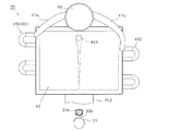
引き継ぎ演出の基本パターンとしては、変動表示の保留がない状態で、始動入賞装置33a、33bに遊技球が入球し(特定入球検知手段としての始動入賞スイッチ224a、224bの検知に基づいて)、引き継ぎ演出が実行されることとなった場合には、図44に示すように、始動入賞装置33a、33bに内蔵された発光手段が発光し、装飾図柄表示装置42において、遊技球が打ち上げられていくかのような表示464(疑似球表示)が行われる。一方、保留されていた変動表示が実行される段階で、引き継ぎ演出が実行されることとなった場合には、図45に示すように、装飾図柄表示装置42の表示部下部中央に打ち上げ装置465が表示され、実行される変動表示に対応する保留アイコン461(遊技球を模した疑似球表示)が、当該打ち上げ装置465にセットされ、打ち上げられる表示464が行われる。
As a basic pattern of the hand-over effect, the game balls enter the
尚、上記のように、保留アイコン461は、表示態様(本例では色)を変化可能に構成されており、当該保留アイコン461から続く演出は、その保留アイコン461の表示態様を引き継ぐこととなる(途中で変わる場合もある)。つまり、例えば、青色の保留アイコン461に対応する変動表示に対応して引き継ぎ演出が行われる場合に、装飾図柄表示装置42において、青色の疑似球を打ち上げる表示が行われ、サブ表示装置48でも青色の疑似球が導出された演出表示が行われる。また、始動入賞装置33a、33bに内蔵されたLEDについても3色LEDであって、始動入賞時に、引き継ぎ演出を行うことが決定された場合に、前記LEDをどの色で発光させるかの抽選等に基づいて、対応する色を発光させ、これに続く演出では、当該発光態様(発光色)が引き継がれるようになっている(途中で変わる場合もある)。
Note that, as described above, the
打ち上げられた遊技球(疑似球表示)は、図46に示すように、サブ表示装置48に表示されたキャラクタ466にキャッチされる。当該キャラクタ466は、複数種類存在し、キャラクタ466と、引き継ぎ演出の成功期待度とが対応している。装飾図柄表示装置42では、「キャラクタが投げた球がゴールまで届いたら当たり」等といった説明表示が導出される。
The launched game ball (pseudo ball display) is caught by the
図47に示すように、サブ表示装置48に表示されたキャラクタ466が疑似球を投じると、センターフレーム47の上辺部に沿って延在する左右一対の発光演出部47aのうち一方(キャラクタ466が左向きで疑似球を投じた場合には左側の発光演出部47a)に内蔵された複数のLED467(正面視で疑似球FBや遊技球と同程度の大きさの円形状をなす)が、サブ表示装置48側のものから演出通路部材406側のものにシフトする格好で、順次、点灯し、消灯する。
As shown in FIG. 47, when the
発光演出部47aの発光態様が演出通路部材406にまで到達すると、図48に示すように、疑似球演出装置49による疑似球FBを使用した疑似球演出が開始される。疑似球演出の基本の成功パターンとしては、左上の第1演出通路421→右上の第2演出通路422→左下の第3演出通路423→右下の第4演出通路424→下ユニット403の順に疑似球FBが通過する。また、図48、図49に示すように、各疑似球演出の間は、左ユニット401の演出通路部材406と、右ユニット402の演出通路部材406との間に位置する装飾図柄表示装置42において、疑似球FBを模した疑似球表示468(つなぎ演出)を導出させることで、演出(引き継ぎ演出の全体)が繋がれるようになっている。尚、演出通路部材406を通過する疑似球FBの色、及び、装飾図柄表示装置42で表示される疑似球表示468の色等により、引き継ぎ演出の成功期待度が示唆される。
When the light emission mode of the light emitting
本実施形態では、図50に示すように、疑似球FBが下ユニット403に到達した時点(下ユニット403において疑似球FBが視認可能な位置に導出された時点)で、引き継ぎ演出が成功となり、大当たり状態が発生することの教示となる。また、下ユニット403では、大当たり状態の種別を教示・示唆する演出(疑似球演出)が行われる。例えば、下ユニット403を移動する疑似球FBの色、及び、下ユニット403の左右一対の押上げ装置432のどちらを経由するかによって、確変大当りとなる期待度が示唆される。その後、押上げ装置432で押し上げられた疑似球FBを装飾図柄表示装置42に表示されたキャラクタ469が受取り、疑似球表示468を扉の窪みに嵌めて扉を開ける態様が導出され、それに続いて表示される装飾図柄表示装置42の表示態様により、大当たり種別が教示・示唆される(装飾図柄が対応する組合わせで停止表示される)ようになっている。
In the present embodiment, as shown in FIG. 50, when the pseudo sphere FB reaches the lower unit 403 (when the pseudo sphere FB is led to a position where the pseudo sphere FB can be visually recognized in the lower unit 403), the succession effect is successful, It is a teaching that a big hit situation occurs. In the
尚、疑似球演出のパターンは特に限定されるものではなく、例えば、サブ表示装置48→右上の第2演出通路422→左上の第1演出通路421→右下の第4演出通路424→下ユニット403の順に疑似球FBが通過したり、サブ表示装置48→左上の第1演出通路421→下ユニット403の順に疑似球FBが通過したり、サブ表示装置48→装飾図柄表示装置42→第3演出通路423→第4演出通路424→下ユニット403の順に疑似球FBが通過したりするパターン等があってもよい。疑似球演出と、疑似球演出との間は、装飾図柄表示装置42の疑似球表示(つなぎ演出)で、適宜、繋ぐことが可能である。また、引き継ぎ演出の間は、装飾図柄表示装置42の表示部のどこかで(小さく)装飾図柄の変動表示を行うこととしてもよいし、装飾図柄を表示しなくてもよい。
The pattern of the pseudo-sphere effect is not particularly limited, and for example, the
尚、本実施形態では、始動入賞装置33a、33bに内蔵された発光手段、装飾図柄表示装置42(遊技球や疑似球表示を打ち上げる表示を行う機能)、サブ表示装置48、発光演出部47aによって誘導表示手段が構成されている。始動入賞装置33a、33bに内蔵されたLED467が発光した態様、装飾図柄表示装置42における遊技球や保留アイコン461(疑似球表示)を打ち上げる表示、サブ表示装置48におけるキャラクタが疑似球を投じる表示、発光演出部47aの発光態様が誘導表示であって、注目部でもある。但し、本実施形態の誘導表示は、遊技球や疑似球FBを連想し易い形態で行われることから、当該誘導表示も引き継ぎ演出に含まることとしてもよい。本実施形態では、誘導表示と、引き継ぎ演出とにより、変動対応演出、及び、期間対応演出が構成される。
In the present embodiment, by means of the light emitting means built in the
図4に示すように、遊技領域の左側方領域、及び、右側方領域の下部には、遊技領域の周縁部に沿って一般入賞装置31が配設されている。一般入賞装置31は、遊技盤30の前面部から前方へ突出し、その上側に遊技球が常時入賞可能な入賞口が開口している。
As shown in FIG. 4, a general winning
また、遊技盤30には、内レール構成部51と外レール構成部52とからなり、発射装置60から発射された遊技球を遊技盤30上部へ案内するレール50が取付けられている。これにより、ハンドル18の回動操作に伴い発射された遊技球は発射レール61及びレール50を通じて、遊技盤30とガラスユニット137との間に形成される遊技領域内に案内される。
Further, the
内レール構成部51の先端部分(図4の左上部)には戻り球防止部材53が取着されている。これにより、一旦、レール50から遊技領域へと案内された遊技球が再度レール50内に戻ってしまうといった事態が防止される。また、外レール構成部52の略先端部(図4の右上部)には、返しゴム54が取着されている。所定以上の勢いで発射された遊技球は、返しゴム54に当たって例えば遊技盤30の略中央部側へ戻されることとなる。
A return ball prevention member 53 is attached to the tip portion (upper left portion in FIG. 4) of the inner
また、本実施形態では、外レール構成部52が遊技盤30の右上部で途絶え、内レール構成部51が遊技盤30の右下部で途絶えている。このため、遊技領域は、レール50及び樹脂ベース38の窓孔39の内周面により画定される。但し、発射装置60にて打出された遊技球が、戻り球防止部材53を通過するまでは、レール50を逆流する場合があるため、内外レール構成部51,52の並行部分は遊技領域から除かれる。
Further, in the present embodiment, the outer
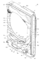
図3に示すように、前面枠セット14の背面側には、窓部101の下方において、球通路ユニット70が設けられている。球通路ユニット70は、後述する払出機構部352から下皿15の下払出口16へ繋がる下皿連通路71と、払出機構部352から上皿19へ繋がる上皿連通路73と備えている。
As shown in FIG. 3, a
また、内枠12の前面側に設けられた発射レール61とレール50(外レール構成部52)との間には所定間隔の隙間があり、前面枠セット14の球通路ユニット70には、前記隙間より落下した遊技球を下皿15へと案内するファール球通路72が形成されている。これにより、仮に、発射装置60から発射された遊技球が戻り球防止部材53まで至らずファール球としてレール50を逆戻りする場合には、そのファール球がファール球通路72を介して下皿15に排出される。
In addition, there is a predetermined gap between the
さらに、図3に示すように、上皿19と、球送り装置63との間を連通させ、上皿19に貯留された遊技球を球送り装置63へと案内する発射球通路74が設けられている。また、図4に示すように、球送り装置63には、当該球送り装置63への遊技球の入口付近において遊技球を検知可能な球詰り検知スイッチ75が設けられている。つまり、球送り装置63は、遊技球を発射装置60によって打出される発射位置に1球ずつ送る送り弁(図示略)を備え、かかる送り弁において球噛みが発生した場合に球詰りが発生するおそれがある。本実施形態では、ハンドル18が操作されている状態において、球詰り検知スイッチ75によって遊技球が所定時間以上検知され続けている場合に、該当部位において球詰りが発生していることを検知するようになっている。
Further, as shown in FIG. 3, a
加えて、発射球通路74(上皿19の下流部でも可)には、下皿連通路71と連通する連通孔(図示略)が形成されるとともに、当該連通孔を開閉させる第1シャッタ(図示略)が設けられている。第1シャッタは、図示しない付勢手段によって常には連通孔を閉鎖する閉位置側へと付勢されている。さらに、第1シャッタは、球抜きボタン123と連動し、球抜きボタン123が押圧操作された場合には、連通孔を開口させる開位置へと変位するように構成されている。
In addition, a communication hole (not shown) that communicates with the lower
また、図2に示すように、下皿15には、下皿15に貯留されている遊技球をパチンコ機10の外部へと排出可能な排出口15aが形成されるとともに、当該排出口15aを開閉させる第2シャッタ15bが設けられている。第2シャッタ15bは、図示しない付勢手段によって常には排出口15aを閉鎖する閉位置側へと付勢されている。さらに、第2シャッタ15bは、球抜きレバー25と連動するように構成されており(例えば、連結、又は、一体形成されており)、球抜きレバー25が(左側へ)押圧操作された場合には、排出口15aを開口させる開位置へと変位するように構成されている。
Further, as shown in FIG. 2, the
加えて、下皿15は、第2シャッタ15bを開位置において保持可能な保持手段(図示略)を備え、遊技者が球抜きレバー25を押圧操作し続けなくても、排出口15aを開位置に保持することができる。尚、保持手段としては、例えば、球抜きレバー25を開位置側へ一杯まで押圧操作することで、球抜きレバー25及び第2シャッタ15b側の所定部位と係止状態とされ、該係止状態から、再度、球抜きレバー25を開位置側へ一杯まで押圧操作することで、前記係止状態が解除されるような構成が挙げられる。
In addition, the
また、図3及び図4中の符号67は後述する払出機構部352により払出された遊技球を内枠12の前方に案内するための払出通路であり、上皿連通路73(上皿19)に通じる通路と、下皿連通路71(下皿15)に通じる通路とに分かれている。払出通路67の下方にはシャッタ68が設けられており、前面枠セット14を開放した状態では、バネ等の付勢力によりシャッタ68が前方に突出して払出通路67の出口をほぼ閉鎖するようになっている。また、前面枠セット14を閉じた状態では、下皿連通路71の入口側後端部によってシャッタ68が押し開けられるようになっている。尚、下皿連通路71及び上皿連通路73の入口(球流入部)が隣接するとともに、前面枠セット14の閉状態において当該各入口と払出通路67とが所定距離だけ離間しており、両者間の隙間を遊技球が通過可能となっている。このため、上皿19及び上皿連通路73が遊技球で満杯となると、払出される遊技球が下皿連通路71側に流れ(下皿連通路71の入口側に溢れ)、下皿連通路71を通って下皿15に払出されることとなる。
加えて、球通路ユニット70には、下皿連通路71内に位置する遊技球を検知する満杯検知スイッチ(図示略)が設けられている。当該満杯検知スイッチの存在により、下皿15が遊技球で満杯になっていること(下皿15が遊技球で満杯となり、下皿連通路71において遊技球が滞留していること)を把握することができる。本実施形態では、満杯検知スイッチによって所定時間継続して遊技球が検知されることに基づき、装飾図柄表示装置42における表示や音声等を用いて下皿15が満杯であることを教示するエラー報知の制御が行われる。尚、下皿連通路71における遊技球の滞留が解消され、満杯検知スイッチにより遊技球が検知されなくなると(所定時間継続して検知されなくなると)エラー報知の状態が解除される。
In addition, the
次に、パチンコ機10の背面構成について図5、図6等を参照して説明する。パチンコ機10の背面には、各種制御基板が上下左右に並べられるようにして、一部前後に重ねられるようにして配置されており、さらに、遊技球を供給する遊技球供給装置(払出機構)や樹脂製の保護カバー等が取り付けられている。払出機構及び保護カバーは1ユニットとして一体化されており、一般に樹脂部分を裏パックと称することもあるため、ここではそのユニットを「裏パックユニット203」と称する。
Next, the rear structure of the
まず、遊技盤30の背面構成について説明する。図6に示すように、遊技盤30中央の貫通孔に対応して配設された可変表示装置ユニット35(図4参照)の背面側には、センターフレーム47を背後から覆う樹脂製のフレームカバー213が後方に突出して設けられている。また、フレームカバー213の背面側には、フレームカバー213の開口部から前方に臨む装飾図柄表示装置42、表示制御装置45及びサブ制御装置262が前後に重ねられた状態で着脱可能に取り付けられている。サブ表示装置48は、センターフレーム47の上部中央に埋設され、前方に露出するようにして設けられている。尚、サブ表示装置48の両側方に設けられる発光演出部47aは、センターフレーム47の上部により構成されてもよいし、センターフレーム47とは別体として構成され、センターフレーム47に取付けられる構成であってもよい。
First, the rear structure of the
装飾図柄表示装置42は、当該装飾図柄表示装置42の表示部(液晶画面)をパチンコ機10の前面側に露出させるための開口部が形成された収容ボックス42aに収容されてフレームカバー213の背面側に固定されている。表示制御装置45は基板ボックス45aに収容されて装飾図柄表示装置42(収容ボックス42a)の背面側に固定されている。サブ制御装置262は基板ボックス262aに収容されて表示制御装置45(基板ボックス45a)の背面側に固定されている。尚、フレームカバー213内には、センターフレーム47(発光演出部47a等)に内蔵されたLED等を駆動するLED制御基板等が配設されている。また、収容ボックス42a及び基板ボックス45a,262aは透明樹脂材料等により構成され、内部が視認可能となっている。
The decorative
フレームカバー213の下方には裏枠セット215が、一般入賞装置31、可変入賞装置32及び始動入賞装置33等を背後から覆うようにして遊技盤30に取付けられている。裏枠セット215は、各種入賞口に入賞した遊技球を回収するための球回収機構を備えている(図示略)。この球回収機構により回収された遊技球は、後述する排出通路部217に案内され、排出通路部217の排出シュートからパチンコ機10外部に排出される。
Below the
また、本実施形態では、裏枠セット215が主制御装置261の取付台として機能する。より詳しくは、主制御装置261を搭載した基板ボックス263が、裏枠セット215に対し回動可能に軸支され、後方に開放可能となっている。
Further, in the present embodiment, the back frame set 215 functions as a mounting base for the
主制御装置261は透明樹脂材料等よりなる基板ボックス263に収容されている。基板ボックス263は、ボックスベースと該ボックスベースの開口部を覆うボックスカバーとを備え、これらボックスベースとボックスカバーとが封印部材によって連結されている。封印部材によって連結された基板ボックス263は、所定の痕跡を残さなければ開封できない構成となっている。これにより、基板ボックス263が不正に開封された旨を容易に発見することができる。
また、遊技盤30には、一般入賞装置31等の各種入賞口に対応して、当該各種入賞口へ入球した遊技球を検知する入球検知スイッチが設けられている。具体的には、図4に示すように、一般入賞装置31に対応する位置には一般入賞スイッチ221が設けられ、可変入賞装置32には、カウントスイッチ223が設けられている。また、第1始動入賞装置33a、及び、第2始動入賞装置33bには、第1始動入賞スイッチ224a、及び、第2始動入賞スイッチ224bが設けられている。さらに、スルーゲート34に対応する位置にはスルーゲートスイッチ225が設けられている。
In addition, the
また、図示は省略するが、裏枠セット215には、一般入賞スイッチ221、カウントスイッチ223、及びスルーゲートスイッチ225とケーブルコネクタを介して電気的に接続される第1盤面中継基板が設けられている。この第1盤面中継基板は、一般入賞スイッチ221等と、主制御装置261とを中継するものであり、ケーブルコネクタを介して主制御装置261と電気的に接続されている。これに対し、第1始動入賞スイッチ224a、第2始動入賞スイッチ224bは中継基板を経ることなくコネクタケーブルを介して直接主制御装置261に接続されている。
Although illustration is omitted, the back frame set 215 is provided with a first board surface relay board which is electrically connected to the general winning
各種入球検知スイッチにて各々検知された検知結果は、主制御装置261に取り込まれる。そして、該主制御装置261よりその都度の入賞状況に応じた払出指令(遊技球の払出個数)が払出制御装置311に送信され、該払出制御装置311からの出力信号に基づき所定数の遊技球の払出しが実施される(スルーゲートスイッチ225により検知された場合を除く)。
The detection results detected by the various ball detection switches are taken into the
この他、図示は省略するが、遊技盤30の裏面には、可変入賞装置32の大入賞口を開放する大入賞口用ソレノイドや、第2始動入賞装置33bの羽根部材37を開閉させるソレノイド等が設けられている。さらに、裏枠セット215には、これらソレノイドやモータと主制御装置261とを中継する第2盤面中継基板(図示略)も設けられている。
In addition, although not shown, on the back surface of the
次に、裏パックユニット203の構成を説明する。図5に示すように、裏パックユニット203は、樹脂成形された裏パック351と、遊技球の払出機構部352とを一体化したものである。また、裏パックユニット203は、内枠12の左側部(図5では右側)に対して開閉可能に支持されており、上下方向に沿って延びる開閉軸線を軸心として後方に開放できるようになっている。加えて、裏パックユニット203の左上部(図5では右上部)には外部端子板240が設けられている。
Next, the configuration of the
外部端子板240は、遊技ホールのホールコンピュータなどへの各種情報送信を中継するためのものであり、複数の外部接続端子が設けられている。便宜上、符号は付さないが、例えば現在の遊技状態(大当たり状態や確変モード等)に関する情報を出力するための端子、後述する開放検知スイッチ91、92によって検知される前面枠セット14や内枠12の開放に関する情報を出力するための端子、入球エラー、下皿満タンエラー、タンク球無しエラー、払出しエラーなど各種エラー状態に関する情報を出力するための端子、払出制御装置311から払出される賞球数に関する情報を出力するための端子などが設けられている。
The external
裏パック351は例えばABS樹脂により一体成形されており、パチンコ機10の後方に突出して略直方体形状をなす保護カバー部354を備えている。保護カバー部354は左右側面及び上面が閉塞され且つ下面のみが開放された形状をなし、少なくともフレームカバー213を覆うのに十分な大きさを有する。但し、本実施形態では、保護カバー部354が基板ボックス263の上部及び右部(図5では左側の部位)も合わせて覆う構成となっている。これにより、裏パックユニット203の閉鎖状態において、基板ボックス263の右部に設けられた封印部材、及び主制御装置261の上縁部に沿って設けられた端子部(基板側コネクタ)が覆われることとなる。
The
払出機構部352は、保護カバー部354を迂回するようにして配設されている。すなわち、保護カバー部354の上方には、上側に開口したタンク355が設けられており、このタンク355には遊技ホールの島設備から供給される遊技球が逐次補給される。タンク355の下方には、例えば横方向2列の球通路を有し下流側に向けて緩やかに傾斜するタンクレール356が連結され、タンクレール356の下流側には縦向きにケースレール357が連結されている。払出装置358はケースレール357の最下流部に設けられ、払出モータ等の所定の電気的構成により必要個数の遊技球の払出が適宜行われる。そして、払出装置358より払出された遊技球は上皿19等に供給される。
The
また、払出機構部352には、払出制御装置311から払出装置358への払出指令の信号を中継する払出中継基板381が設置されると共に、外部より主電源を取り込む電源スイッチ基板382が設置されている。電源スイッチ基板382には、電圧変換器を介して例えば交流24Vの主電源が供給され、電源スイッチ382aの切替操作により電源ON又は電源OFFされる。
Further, in the
裏パックユニット203(基板ボックス263)の下方には、内枠12の左側部(図5では右側)にて軸支され、後方に開放可能な下枠セット251が設けられている。図6に示すように、下枠セット251には、上述した球回収機構により回収された遊技球が流入する排出通路部217が形成され、排出通路部217の最下流部には、遊技球をパチンコ機10外部へ排出する排出シュート(図示略)が形成されている。つまり、一般入賞装置31等の各入賞口に入賞した遊技球は、裏枠セット215の球回収機構を介して集合し、さらに排出通路部217の排出シュートを通じてパチンコ機10外部に排出される。なお、アウト口36も同様に排出通路部217に通じており、何れの入賞口にも入賞しなかった遊技球も排出シュートを介してパチンコ機10外部に排出される。尚、本実施形態では、裏パックユニット203と下枠セット251とが別体として構成され、それぞれ独立して開閉可能であるが、裏パックユニット203と下枠セット251とが一体的に形成されることとしてもよい。
Below the back pack unit 203 (substrate box 263), a lower frame set 251 which is axially supported by the left side portion (right side in FIG. 5) of the
また、図5に示すように、下枠セット251の背面側には、電源・発射制御装置310、払出制御装置311、及び、CRユニット接続基板314が前後に重ねられた状態で着脱可能に取り付けられている。電源・発射制御装置310は、発射制御回路312と、電源回路313とを備え、基板ボックス313aに収容されて下枠セット251の背面側に固定されている。
Further, as shown in FIG. 5, the power supply/launch control device 310, the
また、払出制御装置311は、基板ボックス311aに収容されて、基板ボックス313a(電源・発射制御装置310)の背面側に固定されている。払出制御装置311が収容される基板ボックス311aには、上述した主制御装置261が収容される基板ボックス263と同様に封印部材が設けられ、基板ボックス311aの開封された痕跡が残るようになっている。
The
加えて、CRユニット接続基板314は、基板ボックス314aに収容されて、基板ボックス313a(電源・発射制御装置310)の背面側に固定されている。なお、上記各基板ボックス311a,313a,314aは透明樹脂材料等により構成されており、内部が視認可能となっている。
In addition, the CR
また、払出制御装置311には基板ボックス311aから外方に突出する状態復帰スイッチ321が設けられている。例えば、払出モータの球詰まり等、払出エラーの発生時において状態復帰スイッチ321が押下されると、払出モータが正逆回転され、球詰まりの解消(正常状態への復帰)が図られる。
In addition, the
さらに、電源回路313には基板ボックス313aから外方に突出するRAM消去スイッチ323が設けられている。本パチンコ機10はバックアップ機能を有しており、万一停電が発生した際でも停電時の状態を保持し、停電からの復帰(復電)の際には停電時の状態に復帰させることができる。従って、通常手順で(例えば遊技ホールの営業終了時に)電源遮断すると電源遮断前の状態が記憶保持されることから、電源投入時に初期状態に戻したい場合には、RAM消去スイッチ323を押しながら電源を投入する。
Further, the
また、図6に示すように、内枠12の右側部背面側には施錠装置600が設けられている。施錠装置600は、前面枠セット14の前面側に露出するシリンダ錠700(図1等参照)を備えており、該シリンダ錠700の鍵穴に鍵を挿入し、一方に回動操作することで内枠12を解錠でき、他方に回動操作することで前面枠セット14を解錠できるようになっている。本実施形態では、内枠12は外枠11に対し施錠され、前面枠セット14は内枠12に対し施錠される。
Further, as shown in FIG. 6, a
尚、上記のように、外枠11の右辺枠構成部11dには、施錠装置600に対応する上下区間全域を内枠12の背面側から覆う延出壁部83が形成されている(図5参照)。これにより、外枠11の背面側から線材等を進入させ、当該線材等により施錠装置600を操作することが困難となる。結果として、防御性能の向上を図ることができる。さらに、延出壁部83は、裏パックユニット203及び下枠セット251の右端部(図5では左側の端部)を背面側から覆う構成となっており、内枠12の閉状態においては、裏パックユニット203及び下枠セット251を開放できない構成となっている。
As described above, the right side
また、図4に示すように、内枠12の前面側右下部(発射装置60の右側)には、前面枠セット14の開放を検知するための前面枠開放検知スイッチ91が設けられ、図5に示すように、内枠12の背面側右下部(図5では左下)には、内枠12の開放を検知するための内枠開放検知スイッチ92が設けられている。前面枠開放検知スイッチ91及び内枠開放検知スイッチ92は、それぞれスイッチ本体部に対して出没可能な検知部を備えており、前面枠開放検知スイッチ91は検知部が前方に向くように設けられ、内枠開放検知スイッチ92は検知部が後方へ向くように設けられる。そして、検知部がスイッチ本体部から突出した状態にある場合にはオン信号を主制御装置261に出力し、検知部がスイッチ本体部側に押圧され、スイッチ本体部に没入した状態ではオフ信号を主制御装置261に出力する構成となっている。つまり、前面枠開放検知スイッチ91は前面枠セット14の閉鎖時において検知部が前面枠セット14の背面で押圧されてオフ状態となり、前面枠セット14の開放時には、検知部が突出状態に戻ってオン状態となる。同様に、内枠開放検知スイッチ92は内枠12の閉鎖時において検知部が外枠11の受部85に一体形成された押圧部86によって押圧されてオフ状態となり、内枠12の開放時には検知部が突出状態に戻ってオン状態となる。
Further, as shown in FIG. 4, a front frame opening
次に、パチンコ機10の電気的構成について説明する。図7は、本パチンコ機10の電気的構成を示すブロック図である。主制御手段、抽選手段としての主制御装置261には、演算装置である1チップマイコンとしてのCPU501が搭載されている。CPU501には、該CPU501により実行される各種の制御プログラムや固定値データを記憶したROM502と、そのROM502内に記憶される制御プログラムの実行に際して各種のデータ等を一時的に記憶するメモリであるRAM503と、割込回路やタイマ回路、データ送受信回路などの各種回路等が内蔵されている。但し、CPU、ROM及びRAMが1チップ化されておらず、それぞれの機能毎にチップ化されている構成であってもよい。
Next, the electrical configuration of the
RAM503は、CPU501の内部レジスタの内容やCPU501により実行される制御プログラムの戻り先番地などが記憶されるスタックエリアと、各種フラグ及びカウンタ、I/O等の値が記憶される作業エリア(作業領域)と、バックアップエリア503aとを備えている。
The
また、RAM503は、パチンコ機10の電源のオフ後においても、電源回路313からバックアップ電圧が供給されてデータを保持(バックアップ)できる構成となっており、スタックエリア、作業エリア及びバックアップエリア503aに記憶されるすべてのデータがバックアップされるようになっている。
Further, the
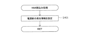
バックアップエリア503aは、停電などの発生により電源が切断された場合において、電源の再入時にパチンコ機10の状態を電源切断前の状態に復帰させるべく、電源切断時(停電発生時を含む。以下同様)のスタックポインタや、各レジスタ、I/O等の値を記憶しておくエリアである。バックアップエリア503aへの書き込みは、メイン処理によって電源切断時に実行され、逆にバックアップエリア503aに書き込まれた各値の復帰は、電源入時(停電解消による電源入を含む。以下同様)のメイン処理において実行される。なお、CPU501のNMI端子(ノンマスカブル割込端子)には、停電等の発生による電源断時に、後述する停電監視回路542から出力される停電信号SK1が入力されるように構成されており、停電の発生により、停電処理(NMI割込み処理)が即座に実行される。
In the case where the power is cut off due to the occurrence of a power failure or the like, the
なお、少なくともスタックエリアとバックアップエリア503aとに記憶されるデータをバックアップすれば、必ずしもすべてのエリアに記憶されるデータをバックアップする必要はない。例えば、スタックエリアとバックアップエリア503aとに記憶されるデータをバックアップし、作業エリアに記憶されるデータをバックアップしない構成としてもよい。
Note that if at least the data stored in the stack area and the
かかるROM502及びRAM503を内蔵したCPU501には、アドレスバス及びデータバス等で構成されるバスライン504を介して入出力ポート505が接続されている。入出力ポート505には、後述するRAM消去スイッチ回路543、払出制御装置311、サブ制御装置262、第1及び第2特別表示装置43a、43b、普通図柄表示装置41等が接続されている。この構成により、上述した特別表示装置43a、43b、及び普通図柄表示装置41は、主制御装置261により直接的に制御される。一方、装飾図柄表示装置42は、サブ制御装置262を介して制御される。
An input/
その他、便宜上、各種中継基板等の図示は省略するが、入出力ポート505には、一般入賞スイッチ221、カウントスイッチ223、始動入賞スイッチ224a,224b、スルーゲートスイッチ225等の各種検知スイッチや、電源・発射制御装置310、払出制御装置311、サブ制御装置262等の各種基板や、保留表示装置46a、46b、普通保留表示装置44、可変入賞装置32を開閉させるためのソレノイド、第2始動入賞装置33b(羽根部材37)を開閉させるためのモータ等の各種電気部品が接続されている。つまり、主制御装置261には、各種ケーブルコネクタのコネクタを接続するための複数の端子部(基板側コネクタ)が設けられているが、これら端子部等により、入出力ポート505が構成される。
In addition, although illustration of various relay boards and the like is omitted for convenience, various detection switches such as a general winning
サブ制御手段としてのサブ制御装置262(サブ制御基板)は、演算装置であるCPU551、該CPU551により実行される各種の制御プログラムや固定値データを記憶したROM552、該ROM552内に記憶される制御プログラムの実行に際して各種のデータ等を一時的に記憶するメモリであるRAM553、入出力ポート554、バスライン555を備えるとともに、その他にも図示しない割込回路やタイマ回路、データ送受信回路などの各種回路等を備えている。RAM553は、CPU551による各種プログラムの実行時に使用されるワークデータやフラグを一時的に記憶するメモリである。
The sub-control device 262 (sub-control board) as a sub-control means includes a
入出力ポート554には、バスライン555を介してCPU551、ROM552、RAM553が接続されるとともに、表示制御装置45が接続されている。さらに、入出力ポート554には、スピーカSP、発光演出部47a、演出ボタン125、十字ボタン126、始動入賞装置33a、33bに内蔵された発光手段、環状電飾部102、及び、エラー表示ランプ104等が接続されている。
To the input/
サブ制御装置262のCPU551は、例えば主制御装置261から送信される指令信号(例えば変動パターンコマンド)に基づいて表示制御装置45に表示制御を実行させ、装飾図柄表示装置42に表示させる。なお、上記のように、本実施形態では、主制御装置261が制御する第1及び第2特別表示装置43a、43bにて大当たりに当選したことを教示するようになっており、サブ制御装置262が制御する装飾図柄表示装置42では、特別表示装置43a、43bにおける特別図柄の変動表示に合わせて、演出表示として装飾図柄の変動表示が行われる。さらに、本実施形態の表示制御装置45は、サブ表示装置48の表示制御についても実行するように構成されている。尚、本実施形態では、サブ制御装置262とともに、表示制御装置45についてもサブ制御手段に含まれる。
The
また、払出制御装置311は、払出装置358により賞球や貸し球の払出制御を行うものである。演算装置であるCPU511は、そのCPU511により実行される制御プログラムや固定値データ等を記憶したROM512と、ワークメモリ等として使用されるRAM513とを備えている。
The
払出制御装置311のRAM513は、主制御装置261のRAM503と同様に、CPU511の内部レジスタの内容やCPU511により実行される制御プログラムの戻り先番地などが記憶されるスタックエリアと、各種フラグ及びカウンタ、I/O等の値が記憶される作業エリア(作業領域)と、バックアップエリア513aとを備えている。
The
RAM513は、パチンコ機10の電源のオフ後においても電源回路313からバックアップ電圧が供給されてデータを保持(バックアップ)できる構成となっており、スタックエリア、作業エリア及びバックアップエリア513aに記憶されるすべてのデータがバックアップされるようになっている。なお、少なくともスタックエリアとバックアップエリア513aとに記憶されるデータをバックアップすれば、必ずしもすべてのエリアに記憶されるデータをバックアップする必要はない。例えば、スタックエリアとバックアップエリア513aとに記憶されるデータをバックアップし、作業エリアに記憶されるデータをバックアップしない構成としてもよい。
The
バックアップエリア513aは、停電などの発生により電源が切断された場合において、電源の再入時にパチンコ機10の状態を電源切断前の状態に復帰させるべく、電源切断時のスタックポインタや、各レジスタ、I/O等の値を記憶しておくエリアである。このバックアップエリア513aへの書き込みは、メイン処理によって電源切断時に実行され、バックアップエリア513aに書き込まれた各値の復帰は電源入時のメイン処理において実行される。なお、主制御装置261のCPU501と同様、CPU511のNMI端子にも、停電等の発生による電源遮断時に停電監視回路542から停電信号SK1が入力されるように構成されており、その停電信号SK1がCPU511へ入力されると、停電時処理としてのNMI割込み処理が即座に実行される。
The
作業エリアには、払出制御装置311による賞球の払出許可が設定される払出許可フラグと、主制御装置261から送信されたコマンドを受信した場合に設定されるコマンド受信フラグと、主制御装置261から送信されたコマンドが記憶されるコマンドバッファとが設けられている。
In the work area, a payout permission flag in which payout control of the
払出許可フラグは、賞球の払出許可を設定するフラグであり、主制御装置261から賞球の払出を許可する特定のコマンドが送信され、その特定のコマンドを受信した場合にオンされ、初期設定の処理又は電源遮断前へ復帰された場合にオフされる。本実施形態では、特定のコマンドは、払出制御装置311のRAM513の初期処理の指示をする払出初期化コマンドと、賞球の払出を指示する賞球コマンドと、主制御装置261が復電された場合に送信される払出復帰コマンドの3つである。
The payout permission flag is a flag for setting payout permission of prize balls, and is turned on when a specific command permitting payout of prize balls is transmitted from the
コマンド受信フラグは、払出制御装置311がコマンドを受信したか否かを確認するフラグであり、いずれかのコマンドを受信した場合にオンされ、払出許可フラグと同様に、初期設定の処理又は電源遮断前へ復帰された場合にオフされるとともに、コマンド判定処理により受信されたコマンドの判定が行われた場合にオフされる。
The command reception flag is a flag for confirming whether or not the
コマンドバッファは、主制御装置261から送信されるコマンドを一時的に記憶するリングバッファで構成されている。リングバッファは所定の記憶領域を有しており、その記憶領域の始端から終端に至るまで規則性をもってコマンドが記憶され、全ての記憶領域にコマンドが記憶された場合には、記憶領域の始端に戻りコマンドが更新されるよう構成されている。よって、コマンドが記憶された場合及びコマンドが読み出された場合に、コマンドバッファにおける記憶ポインタ及び読出ポインタが更新され、その各ポインタに基づきコマンドの記憶と読み出しとが行われる。
The command buffer is composed of a ring buffer that temporarily stores commands transmitted from
かかるROM512及びRAM513を内蔵したCPU511には、アドレスバス及びデータバスで構成されるバスライン514を介して入出力ポート515が接続されている。入出力ポート515には、RAM消去スイッチ回路543、主制御装置261、電源・発射制御装置310(発射制御回路312)、払出装置358、CRユニット接続基板314等がそれぞれ接続されている。また、本実施形態では、球送り装置63における球詰りを検知するための球詰り検知スイッチ75についても、払出制御装置311の入出力ポート515に接続されている。
An input/
CRユニット接続基板314は、パチンコ機10前面の貸球操作部(貸出スイッチ121及び返却スイッチ122)と、遊技ホール等にてパチンコ機10の側方に配置されるCRユニット(カードリーダーユニット、球貸しユニット)のCRユニット制御装置と、払出制御装置311とにそれぞれ電気的に接続されている。尚、貸出スイッチ121、返却スイッチ122、及び、残高表示部124は、パチンコ機10に搭載されているものの、CRユニットによる遊技球の貸出操作に関する構成であることから、実質的にCRユニットに含まれるものである。また、CRユニット接続基板314についても、パチンコ機10に搭載されているものの、CRユニット制御装置と、貸出スイッチ121、返却スイッチ122、及び、残高表示部124との間や、CRユニット制御装置と、払出制御装置311との間を電気的に接続するものであることから、実質的にはCRユニットに含まれるものである。
The CR
そして、遊技者による貸球操作部、又は、CRユニットの本体に設けられたボタンへの球貸し操作に関する情報がCRユニット制御装置に入力され、かつ、CRユニットに挿入されている記録媒体(遊技価値媒体)であるカードに遊技価値の残高が記憶されている場合には、カードの残高が減算されるとともに、減算に対応する数の遊技球の貸出要求信号が払出制御装置311に出力される。なお、CRユニットの記録媒体は、カードタイプに限定されず、コインタイプやスティックタイプのものであってもよい。
Then, the information about the ball lending operation section by the player or the ball lending operation to the button provided on the main body of the CR unit is input to the CR unit control device, and the recording medium inserted in the CR unit (game When the game value balance is stored in the card that is the value medium), the card balance is decremented, and at the same time, a lending request signal for the number of gaming balls corresponding to the deduction is output to the
尚、CRユニットには、現金投入部に投入された金額を読取可能なマネーリーダと、カード挿入部に挿入されたカードに記憶されている残高を読取可能なカード制御部とが設けられている。さらに、CRユニットが利用可能な状態であることを示すカード利用可ランプ(エラーで点滅)、カードが挿入状態であることを示すカード挿入中ランプ、カード残高を示すカード残高表示部、遊技球を貸出可能な状態であることを示す貸出スイッチLED等が設けられている。 It should be noted that the CR unit is provided with a money reader capable of reading the amount of money inserted into the cash insertion unit and a card control unit capable of reading the balance stored in the card inserted into the card insertion unit. .. In addition, a card available lamp (flashing with an error) indicating that the CR unit is available, a card insertion lamp indicating that a card is inserted, a card balance display section indicating the card balance, and a game ball are displayed. A lending switch LED or the like indicating that the lending is possible is provided.
また、本実施形態では、CRユニットがパチンコ機10に対して貸出要求信号を出力し、パチンコ機10の遊技球を払出す機能を利用して、遊技者(上皿19等に)に遊技球を貸出す構成となっているが、例えば、CRユニットが、遊技球を払出可能な機能を備え、貸出スイッチ121の操作が行われた場合に、CRユニットから延びる案内管を通じて、上皿19に遊技球が貸出されるように構成してもよい。
In addition, in the present embodiment, the CR unit outputs a lending request signal to the
また、払出制御装置311は、CRユニット接続基板314と、CRユニットとが電気的に接続されていることを示すCRユニット接続信号を電源・発射制御装置310の発射制御回路312に対して定期的(例えば、2msec毎)に出力するように構成されている。
Further, the
電源・発射制御装置310の発射制御回路312は、発射装置60による遊技球の発射を許可又は禁止するものである。発射制御回路312には、ハンドル18、払出制御装置311、主制御装置261が電気的に接続されている。また、発射制御回路312は、ハンドル18から、ハンドル18(回転操作体18a)の回動操作量(回転角度)を示す可変抵抗器からのダイヤル位置信号と、遊技者がハンドル18をタッチしていることを示すタッチセンサからのタッチ信号と、遊技者がストップレバー18bを操作していないことを示す発射スイッチ信号とを入力可能に構成されている。さらに、発射制御回路312は、払出制御装置311から、CRユニット接続基板314と、CRユニットとが電気的に接続されていることを示すCRユニット接続信号を入力可能に構成されている。
The
そして、発射制御回路312は、タッチ信号、発射スイッチ信号、及び、CRユニット接続信号が入力されていることを条件に、発射状態信号を主制御装置261に出力し、主制御装置261では、発射状態信号が入力されていることを条件に、発射許可信号、及び、球送り信号を発射制御回路312に出力する。主制御装置261は、発射状態信号が入力されている状態において、0.6秒間隔で、発射許可信号が出力されるようになっている。
Then, the firing
また、発射制御回路312は、球送り信号が入力された場合に、球送り装置63を駆動させ、遊技球を発射位置に送るように構成されている。尚、球送り装置63に設けられ、発射位置に遊技球が存在するか否かを検知可能な準備球検知センサを設け、当該準備球検知センサによって発射位置に既に遊技球が存在すると検知される状態においては、球送り装置63を駆動させない(球送り信号を受信しても、遊技球を発射位置に送らない)ように構成してもよい。
Further, the
さらに、発射制御回路312は、タッチ信号、発射スイッチ信号、CRユニット接続信号、(ダイヤル位置信号、)及び、発射許可信号が入力されていることを条件に、発射装置60(発射ソレノイド)を駆動させるように構成されている。これにより、発射位置にセットされた遊技球が、発射装置60により、ダイヤル位置信号に基づく強さで打ち出されるようになっている。
Further, the firing
また、電源回路313は、パチンコ機10の各部に電力を供給する電源部541と、停電等による電源遮断を監視する停電監視回路542と、RAM消去スイッチ323に接続されてなるRAM消去スイッチ回路543とを備えている。
Further, the
電源部541は、図示しない電源経路を通じて、主制御装置261や払出制御装置311等に対して各々に必要な動作電源を供給する。その概要としては、電源部541は、外部より供給される交流24ボルト電源を取り込み、各種スイッチやモータ等を駆動する+12V電源、ロジック用の+5V電源、RAMバックアップ用のバックアップ電源などを生成し、これら+12V電源、+5V電源及びバックアップ電源を主制御装置261や払出制御装置311等に対して供給する。なお、各種スイッチやモータ等には、これらが接続される制御装置を介して動作電源が供給されることとなる。
The
停電監視回路542は、停電等の発生による電源断時に、主制御装置261のCPU501及び払出制御装置311のCPU511の各NMI端子へ停電信号SK1を出力する回路である。停電監視回路542は、電源部541から出力される最大電圧である直流安定24ボルトの電圧を監視し、この電圧が22ボルト未満になった場合に停電(電源断)の発生と判断して、停電信号SK1を主制御装置261及び払出制御装置311へ出力する。この停電信号SK1の出力によって、主制御装置261及び払出制御装置311は、停電の発生を認識し、停電時処理(NMI割込み処理)を実行する。
The power
なお、電源部541は、直流安定24ボルトの電圧が22ボルト未満になった後においても、かかる停電時処理の実行に充分な時間の間、制御系の駆動電圧である5ボルトの出力を正常値に維持するように構成されている。よって、主制御装置261及び払出制御装置311は、停電時処理を正常に実行し完了することができる。
Note that the
RAM消去スイッチ回路543は、RAM消去スイッチ323のスイッチ信号を取り込み、そのスイッチ323の状態に応じて主制御装置261のRAM503及び払出制御装置311のRAM513のバックアップデータをクリアする回路である。RAM消去スイッチ323が押下された際、RAM消去スイッチ回路543は、RAM消去信号SK2を主制御装置261及び払出制御装置311に出力する。RAM消去スイッチ323が押下された状態でパチンコ機10の電源が投入されると(停電解消による電源入を含む)、主制御装置261及び払出制御装置311においてそれぞれのRAM503,513のデータがクリアされる。
The RAM erasing
表示制御装置45は、サブ制御装置262からの指示に従い、装飾図柄表示装置42における装飾図柄の変動表示を実行するものである。この表示制御装置45は、CPU521と、プログラムROM522と、ワークRAM523と、ビデオRAM524と、キャラクタROM525と、ビデオディスプレイプロセッサ(VDP)526と、入力ポート527と、出力ポート529と、バスライン530,531とを備えている。入力ポート527にはサブ制御装置262の入出力ポート554が接続されている。また、入力ポート527には、バスライン530を介して、CPU521、プログラムROM522、ワークRAM523、VDP526が接続されている。また、VDP526にはバスライン531を介して出力ポート529が接続されており、その出力ポート529には液晶表示装置たる装飾図柄表示装置42が接続されている。
The
表示制御装置45のCPU521は、サブ制御装置262から送信される表示コマンドを、入力ポート527を介して受信するとともに、受信コマンドを解析し又は受信コマンドに基づき所定の演算処理を行ってVDP526の制御(VDP526に対する内部コマンドの生成)を実施する。これにより、装飾図柄表示装置42における表示制御を行う。
The
プログラムROM522は、そのCPU521により実行される各種の制御プログラムや固定値データを記憶するメモリであり、ワークRAM523は、CPU521による各種プログラムの実行時に使用されるワークデータやフラグを一時的に記憶するメモリである。
The
ビデオRAM524は、装飾図柄表示装置42に表示される表示データを記憶するメモリであり、このビデオRAM524の内容を書き替えることにより、装飾図柄表示装置42の表示内容が変更される。キャラクタROM525は、装飾図柄表示装置42に表示される図柄などのキャラクタデータを記憶するメモリである。
The
VDP526は、装飾図柄表示装置42に組み込まれたLCDドライバ(液晶駆動回路)を直接操作する一種の描画回路である。VDP526はICチップ化されているため「描画チップ」とも呼ばれ、その実体は、描画処理専用のファームウェアを内蔵したマイコンチップとでも言うべきものである。VDP526は、CPU521、ビデオRAM524等のそれぞれのタイミングを調整してデータの読み書きに介在するとともに、ビデオRAM524に記憶される表示データを所定のタイミングで読み出して装飾図柄表示装置42に表示させる。
The
尚、本実施形態では、出力ポート529に対し、液晶表示装置により構成されるサブ表示装置48が接続されている。当該サブ表示装置48についても、表示制御装置45が、サブ制御装置262からの指示に基づいて、演出表示を導出する。
In the present embodiment, the
次に、上記の如く構成されたパチンコ機10の動作について説明する。本実施形態では、主制御手段としての主制御装置261に設けられたCPU501は、遊技に際し各種カウンタ情報を用いて抽選を行うこととしている。具体的には、図8に示すように、大当たり状態を発生させるか否かの当否抽選に使用する当否乱数生成手段としての当否乱数カウンタC1と、大当たり種別の決定(種別抽選)に使用する種別決定カウンタC2と、装飾図柄表示装置42においてリーチ状態を発生させるか否かの決定に使用する変動選択カウンタC3と、当否乱数カウンタC1の初期値設定に使用する初期値乱数カウンタCINIと、第1及び第2特別表示装置43a、43b(装飾図柄表示装置42)の変動表示時間の決定等に使用する第1変動種別カウンタCS1、第2変動種別カウンタCS2と、第2始動入賞装置33bを開状態とさせるか否かの入球サポート抽選に使用する普通図柄乱数カウンタC4とを用いることとしている。なお、変動選択カウンタC3は、装飾図柄表示装置42を外れ変動させる際のリーチパターンの抽選にも使用される。また、変動種別カウンタCS1、CS2は、装飾図柄表示装置42の変動パターン選択(演出パターン選択)にも使用される。
Next, the operation of the
カウンタC1、C2、C3、CINI、CS1、CS2、C4は、その更新の都度前回値に1が加算され、上限値に達した後、下限値である0に戻るループカウンタとなっている。各カウンタは定期的に更新され、その更新値がRAM503の所定領域に設定されたカウンタ用バッファに適宜格納される(乱数初期値カウンタCINIを除く)。 Each of the counters C1, C2, C3, CINI, CS1, CS2, C4 is a loop counter in which 1 is added to the previous value each time it is updated, and after reaching the upper limit value, it returns to 0 which is the lower limit value. Each counter is updated periodically, and the updated value is appropriately stored in a counter buffer set in a predetermined area of the RAM 503 (excluding the random number initial value counter CINI).
RAM503には、当否乱数カウンタC1、種別決定カウンタC2、及び、変動選択カウンタC3の各値が記憶される保留記憶手段としての特別変動保留エリアと、普通図柄乱数カウンタC4の値が記憶される普通変動保留エリアとが設けられている。普通変動保留エリアは、4つの保留エリア(保留第1〜保留第4エリア)と、1つの実行エリアとを備えている。普通変動保留エリアの各保留エリアには、スルーゲート34への遊技球の通過履歴に合わせて、普通図柄乱数カウンタC4の値が時系列的に格納される。当該構成を採用することで、普通図柄表示装置41における変動表示を4回まで保留可能としている。
In the
また、特別変動保留エリアは、それぞれ4つの保留エリア(保留第1〜保留第4エリア)を備える第1特別変動保留エリア、及び、第2特別変動記憶エリアと、1つの実行エリアとを備えている。第1特別変動保留エリアの各保留エリアには、第1始動入賞装置33aへの遊技球の入賞履歴に合わせて、当否乱数カウンタC1、種別決定カウンタC2、及び変動選択カウンタC3の各値が時系列的に格納される。第2特別変動保留エリアの各保留エリアには、第2始動入賞装置33bへの遊技球の入賞履歴に合わせて、当否乱数カウンタC1、種別決定カウンタC2、及び変動選択カウンタC3の各値が時系列的に格納される。当該構成を採用することで、特別表示装置43a、43bにおける変動表示(第1変動表示、及び、第2変動表示)をそれぞれ4回まで保留可能としている。
In addition, the special fluctuation reservation area includes a first special fluctuation reservation area including four reservation areas (reservation first to fourth reservation areas), a second special fluctuation storage area, and one execution area. There is. In each of the holding areas of the first special variation holding area, the respective values of the winning/discarding random number counter C1, the type determination counter C2, and the variation selection counter C3 are set according to the winning history of the game ball to the first
各カウンタについて詳しく説明すると、当否乱数カウンタC1は、例えば0〜637の範囲内で順に1ずつ加算され、終値としての上限値(つまり637)に達した後、始値としての下限値である0に戻る構成となっている。通常、当否乱数カウンタC1が1周した場合、その時点の初期値乱数カウンタCINIの値が当該当否乱数カウンタC1の次の初期値として読み込まれる。なお、初期値乱数カウンタCINIは、当否乱数カウンタC1と同様のループカウンタであり(値=0〜637)、タイマ割込み毎に1回更新されると共に通常処理の残余時間内で繰り返し更新される。一方、当否乱数カウンタC1は定期的に(本実施形態ではタイマ割込み毎に1回)更新され、当否乱数カウンタC1の値が当否乱数カウンタバッファに格納される。そして、遊技球が第1始動入賞装置33a又は第2始動入賞装置33bに入賞したタイミングで、当否乱数カウンタバッファに格納されている当否乱数カウンタC1の値が、特別変動保留エリアに記憶される。
Explaining each counter in detail, the success/failure random number counter C1 is sequentially incremented by 1 in the range of 0 to 637, for example, and after reaching the upper limit value (that is, 637) as the final value, the
また、本実施形態では、低確率状態(通常モード、時間短縮モード)であれば大当たりとなる当否乱数カウンタC1の値の数は2つで、その値は「7、307」であり、高確率状態(確変モード)であれば大当たりとなる当否乱数カウンタC1の値の数は20で、その値は「7〜11、307〜311」である。本実施形態では、ROM502に対し、当否乱数カウンタC1の値が大当たりに対応するか否かの判定を行う際に参照される当選値記憶手段としての当否判定テーブルが2つ設けられており、「7、307」を大当たり値として記憶した第1当否判定テーブルと、「8〜11、308〜311」を大当たり値として記憶した第2当否判定テーブルとがある。
Further, in the present embodiment, the number of values of the success/failure random number counter C1 that is a big hit in the low probability state (normal mode, time shortening mode) is two, and the value is “7,307”, and the high probability. In the state (probability change mode), the number of values of the success/failure random number counter C1 that is a big hit is 20, and the values are “7 to 11, 307 to 311”. In the present embodiment, the
種別決定カウンタC2は、例えば0〜19の範囲内で順に1ずつ加算され、上限値(つまり19)に達した後、下限値である0に戻る構成となっている。また、ROM502には、種別決定カウンタC2の値がいずれの大当たり種別に対応するかの判定を行う際に参照される種別判定テーブルが2つ設けられており、第1始動入賞装置33aへの入球に対応する大当たりに際して参照される第1種別判定テーブルと、第2始動入賞装置33bへの入球に対応する大当たりに際して参照される第2種別判定テーブルとがある。そして、当否抽選にて大当たりに当選した場合に、種別決定カウンタC2の値に基づいて付与される大当たり状態の種別が決定され(種別抽選が行われ)、決定された種別の大当たり状態が付与されることとなる。尚、第1始動入賞装置33a及び第2始動入賞装置33bのどちらへの入球に対応する大当たりでも、大当たり種別の振分けを同じとし、種別判定テーブルを1つとしてもよい。
The type determination counter C2 is configured to be sequentially incremented by 1 in the range of 0 to 19, for example, and after reaching the upper limit value (that is, 19), returns to 0 which is the lower limit value. In addition, the
尚、種別決定カウンタC2は定期的に(本実施形態ではタイマ割込み毎に1回)更新され、種別決定カウンタC2の値が種別決定カウンタバッファに格納される。そして、遊技球が第1始動入賞装置33a又は第2始動入賞装置33bに入賞したタイミングで、種別決定カウンタバッファに格納されている種別決定カウンタC2の値がRAM503の特別変動保留エリアに格納される。
The type determination counter C2 is updated periodically (in this embodiment, once for each timer interrupt), and the value of the type determination counter C2 is stored in the type determination counter buffer. Then, the value of the type determination counter C2 stored in the type determination counter buffer is stored in the special variation holding area of the
変動選択カウンタC3は、例えば0〜238の範囲内で順に1ずつ加算され、上限値(つまり238)に達した後、下限値である0に戻る構成となっている。本実施形態では、変動選択カウンタC3によって、装飾図柄に関してリーチ状態が発生した後、最終停止図柄がリーチ図柄の前後に1つだけずれて停止する「前後外れリーチ」と、同じくリーチ状態が発生した後最終停止図柄がリーチ図柄の前後以外で停止する「前後外れ以外リーチ」と、リーチ状態が発生しない「完全外れ」とを抽選することとしている。本実施形態では、ROM502に対し、変動選択カウンタC3の値とリーチパターンとの対応関係を記憶しているリーチ判定テーブルが1つであるが、例えば、第1始動入賞装置33aへの遊技球の入球を契機として取得された変動選択カウンタC3の値に基づいて(大当たりしない場合の)リーチパターンを決定する際に参照される第1リーチ判定テーブルと、第2始動入賞装置33bへの遊技球の入球を契機として取得された変動選択カウンタC3の値に基づいて(大当たりしない場合の)リーチパターンを決定する際に参照される第2リーチ判定テーブルとを設けることとしてもよい。さらに、例えば、低入球状態に際して第1リーチ判定テーブルを参照し、高入球状態に際して第2リーチ判定テーブルを参照するように構成してもよいし、通常モードに際して第1リーチ判定テーブルを参照し、時間短縮モードに際して第2リーチ判定テーブルを参照し、確変モードに際して第3リーチ判定テーブルを参照するように構成してもよい。
The variation selection counter C3 is configured to be sequentially incremented by 1 in the range of 0 to 238, for example, and after reaching the upper limit value (that is, 238), returns to the
変動選択カウンタC3は定期的に(本実施形態ではタイマ割込み毎に1回)更新され、変動選択カウンタバッファに変動選択カウンタC3の値が格納される。そして、遊技球が第1始動入賞装置33a又は第2始動入賞装置33bに入賞したタイミングで、変動選択カウンタバッファに格納されている変動選択カウンタC3の値がRAM503の特別変動保留エリアに格納される。
The fluctuation selection counter C3 is updated regularly (once in each timer interrupt in this embodiment), and the value of the fluctuation selection counter C3 is stored in the fluctuation selection counter buffer. The value of the variation selection counter C3 stored in the variation selection counter buffer is stored in the special variation reservation area of the
また、2つの変動種別カウンタCS1、CS2のうち、一方の変動種別カウンタCS1は、例えば0〜255の範囲内で順に1ずつ加算され、上限値(つまり255)に達した後、下限値である0に戻る構成となっており、他方の変動種別カウンタCS2は、例えば0〜31の範囲内で順に1ずつ加算され、上限値(つまり31)に達した後、下限値である0に戻る構成となっている。加えて、特別表示装置43a、43bにおける変動表示の変動時間と、装飾図柄表示装置42における変動表示の大まかな変動パターン(ノーマルリーチ、スーパーリーチ、プレミアムリーチ等のリーチパターン)とが対応付けられており、特別表示装置43a、43bの変動時間が決まれば、装飾図柄表示装置42の変動パターンも決まる(特別表示装置43a、43bにおける変動表示の変動時間に丁度収まるような装飾図柄表示装置42における変動パターンを選択させる)ようになっている。
Further, of the two fluctuation type counters CS1 and CS2, one fluctuation type counter CS1 is sequentially incremented by 1 in the range of 0 to 255, for example, and reaches the upper limit value (that is, 255), and then the lower limit value. The variation type counter CS2 is configured to return to 0, and the other variation type counter CS2 is incremented by 1 in the range of 0 to 31, for example, and after reaching the upper limit value (that is, 31), returns to the lower limit value of 0. Has become. In addition, the variation time of the variable display on the
尚、変動時間や変動パターンを決定するために使用されるカウンタ等は特に限定されるものではなく、機種毎に適宜変更可能である。例えば、第1変動種別カウンタCS1だけで装飾図柄のリーチパターンを決定することも可能である。さらに、リーチパターンを決定するテーブルについても特に限定されるものではなく、数、遊技状態との対応付け、内容等については、機種毎に適宜設定される。 The counter and the like used for determining the fluctuation time and the fluctuation pattern are not particularly limited, and can be appropriately changed for each model. For example, it is possible to determine the reach pattern of the decorative pattern only by the first variation type counter CS1. Further, the table for determining the reach pattern is not particularly limited, and the number, the correspondence with the game state, the content, etc. are appropriately set for each model.
また、変動種別カウンタCS1、CS2は、後述する通常処理が1回実行される毎に1回更新され、当該通常処理の残余時間内でも繰り返し更新される。そして、装飾図柄表示装置42による装飾図柄の変動開始時における変動パターン決定に際してCS1、CS2のバッファ値が取得される。
The fluctuation type counters CS1 and CS2 are updated once each time a normal process described later is executed, and are repeatedly updated within the remaining time of the normal process. Then, the buffer values of CS1 and CS2 are acquired when the variation pattern is determined by the decoration
なお、各カウンタの大きさや範囲は一例にすぎず任意に変更できる。但し、当否乱数カウンタC1、種別決定カウンタC2、変動選択カウンタC3、変動種別カウンタCS1、CS2の大きさは何れも異なる素数とし、いかなる場合にも同期しない数値としておくのが望ましい。 The size and range of each counter are merely examples and can be changed arbitrarily. However, it is desirable that the numbers of the random number counter C1, the type determination counter C2, the variation selection counter C3, and the variation type counters CS1 and CS2 are different prime numbers and are not synchronized in any case.
また、普通図柄乱数カウンタC4は、例えば0〜232の範囲内で順に1ずつ加算され、上限値(つまり232)に達した後、下限値である0に戻るループカウンタとして構成されている。普通図柄乱数カウンタC4は定期的に(本実施形態ではタイマ割込み毎に1回)更新され、遊技球が左右何れかのスルーゲート34を通過した時に普通図柄乱数カウンタC4の値が取得される。低入球状態の際の当選となる乱数の値の数は1であり、その範囲は「1」である。一方、高入球状態の際の当選となる乱数の値の数は232であり、その範囲は「1〜232」である。つまり、本実施形態では、ROM502に対し、低入球状態での入球サポート抽選において参照される低入球時サポート判定テーブルと、高入球状態での入球サポート抽選において参照される高入球時サポート判定テーブルとが用意されている。そして、当選となる普通図柄乱数カウンタC4の値が取得された場合、普通図柄表示装置41において変動表示が所定時間行われた後(普通図柄表示装置41を構成する普図ランプが交互に点滅した後)、当選に対応する態様(点灯の組合せ)で停止表示され、第2始動入賞装置33bがそのときの遊技モードに応じたパターンで開放される。
Further, the normal symbol random number counter C4 is configured as a loop counter that is sequentially incremented by one in the range of 0 to 232, for example, and then returns to the lower limit value of 0 after reaching the upper limit value (that is, 232). The normal symbol random number counter C4 is updated regularly (once in each of the timer interrupts in this embodiment), and the value of the normal symbol random number counter C4 is acquired when the game ball passes through either the left or right through
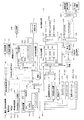
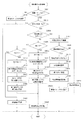
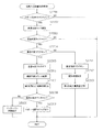
次いで、主制御装置261内のCPU501により実行される各制御処理を、フローチャートを参照しながら説明する。かかるCPU501の処理としては大別して、電源投入に伴い起動されるメイン処理と、定期的に(本実施形態では2msec周期で)起動されるタイマ割込み処理と、NMI端子(ノンマスカブル端子)への停止信号の入力により起動されるNMI割込み処理とがあり、説明の便宜上ここでは、先ずタイマ割込み処理とNMI割込み処理とを説明し、その後でメイン処理を説明する。
Next, each control process executed by the CPU 501 in the
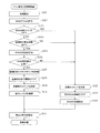
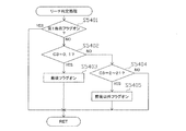
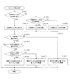
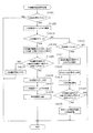
図11は、タイマ割込み処理を示すフローチャートであり、本処理は主制御装置261のCPU501により例えば2msec毎に実行される。先ずステップS301では、各種入賞スイッチの読み込み処理を実行する。すなわち、主制御装置261に接続されている各種スイッチ(但し、RAM消去スイッチ323を除く)の状態を読み込むと共に、当該スイッチの状態を判定して検知情報(入賞検知情報)を保存する。一方、検知情報がない場合には、そのまま次の処理に移行する。
FIG. 11 is a flowchart showing the timer interrupt processing, and this processing is executed by the CPU 501 of the
尚、各種入賞スイッチの検知情報があった場合、対応する賞球カウンタの値を加算する。また、後述する通常処理の外部出力処理において、各賞球カウンタの値に基づく賞球コマンドが払出制御装置311へ出力され、賞球コマンドに基づいて賞球が付与される(遊技球が払出される)。さらに、この賞球コマンドの出力に際して、各賞球カウンタの値がリセットされる。
In addition, when there is the detection information of the various winning switches, the value of the corresponding prize ball counter is added. In an external output process of a normal process described later, a prize ball command based on the value of each prize ball counter is output to the
ステップS302では乱数初期値更新処理を実行する。具体的には、乱数初期値カウンタCINIを1インクリメントすると共に、そのカウンタ値が最大値に達した際0にクリアする。 In step S302, random number initial value update processing is executed. Specifically, the random number initial value counter CINI is incremented by 1, and is cleared to 0 when the counter value reaches the maximum value.
また、ステップS303では乱数更新処理を実行する。具体的には、当否乱数カウンタC1、種別決定カウンタC2、変動選択カウンタC3、及び普通図柄乱数カウンタC4をそれぞれ1インクリメントすると共に、それらのカウンタ値が最大値に達した際それぞれ0にクリアする。そして、各カウンタC1、C2、C3、C4の更新値を、RAM503の該当するバッファ領域に格納する。
In step S303, random number update processing is executed. Specifically, the win/fail random number counter C1, the type determination counter C2, the variation selection counter C3, and the normal symbol random number counter C4 are each incremented by 1, and when the counter values reach the maximum value, they are cleared to 0. Then, the updated values of the counters C1, C2, C3, C4 are stored in the corresponding buffer areas of the
その後、ステップS304では、始動入賞装置33への入賞に伴う始動入賞処理を実行し、ステップS305では、スルーゲート34への遊技球の通過に伴うスルーゲート通過処理を実行する。続くステップS306では、電源・発射制御装置310の発射制御回路312に対して発射許可信号を送信する等の処理を行うための発射許可コマンド設定処理を行う。その後、タイマ割込み処理を一旦終了する。
After that, in step S304, the start winning process associated with winning the start winning device 33 is executed, and in step S305, the through gate passing process associated with passing of the game ball to the through
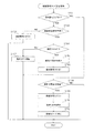
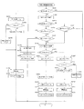
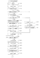
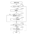
ここで、ステップS304の始動入賞処理について図13のフローチャートを参照して説明する。尚、RAM503には、第1始動入賞装置33aへの入賞を契機とする第1変動表示の保留数をカウントする第1保留カウンタNa、第2始動入賞装置33bへの入賞を契機とする第2変動表示の保留数をカウントする第2保留カウンタNbが設けられている。尚、保留されている変動表示の総数(第1変動表示の保留数と、第2変動表示の保留数とを合わせた数)をカウントする保留総数カウンタを設けることとしてもよい。
Here, the starting winning process of step S304 will be described with reference to the flowchart of FIG. It should be noted that the
また、特別変動保留エリアの実行エリア及び各保留エリアには、当否関連情報としての当否乱数カウンタC1の値を記憶する当否乱数記憶エリア、種別決定カウンタC2の値を記憶する当選種別乱数記憶エリア、変動選択カウンタC3の値を記憶するリーチ乱数記憶エリアが設けられている。 Further, in the execution area and each of the holding areas of the special variation holding area, a winning/discarding random number storage area that stores the value of the winning/discarding random number counter C1 as winning/unlocking related information, a winning type random number storing area that stores the value of the type determining counter C2, A reach random number storage area for storing the value of the fluctuation selection counter C3 is provided.
さらに、特別変動保留エリアの実行エリアには、第1始動入賞装置33aへの入球に基づく第1変動表示であるのか、或いは、第2始動入賞装置33bへの入球に基づく第2変動表示であるのかを示す情報が記憶される変動記憶エリアが設けられている。以下、「変動記憶エリアに第1変動表示であることを示す情報が記憶されること」を「第1変動フラグがオン設定される」とも称し、「変動記憶エリアに第2変動表示であることを示す情報が記憶されること」を「第2変動フラグがオン設定される」とも称する。
Further, in the execution area of the special variation holding area, whether the first variation display based on the ball entered into the first start
先ず、ステップS501では、遊技球が第2始動入賞装置33bに入賞したか否かを第2始動入賞スイッチ224bの検知情報により判別する。当該ステップS501で肯定判別された場合、ステップS502において、第2保留カウンタNbの値が上限値(本実施形態では「4」)未満であるか否かを判別する。ステップS501又はS502で否定判別された場合には、ステップS510に移行する。一方、ステップS502で肯定判別された場合には、ステップS503に進み、第2保留カウンタNbを1インクメントする。
First, in step S501, it is determined whether or not the game ball has won the second
続くステップS504では、第2変動表示の保留数が1つ増えたことに対応する第2保留表示装置46b(第2保留ランプ)の加算表示処理を行う。つまり、左右一対の第2保留ランプが両方とも消灯状態であった場合には左側の第2保留ランプを点灯させ、左側の第2保留ランプが点灯状態であり右側の第2保留ランプが消灯状態であった場合には左右両方の第2保留ランプを点灯させ、左右両方の第2保留ランプが点灯状態であった場合には右側の第2保留ランプを点灯させたまま左側の第2保留ランプを点滅させ、左側の第2保留ランプが点滅状態であり右側の第2保留ランプが点灯状態であった場合には左右両方の第2保留ランプを点滅させるための処理を行う。 In a succeeding step S504, an addition display process of the second hold display device 46b (second hold lamp) corresponding to the increase in the number of hold of the second variable display by 1 is performed. That is, when both the pair of left and right second holding lamps are off, the left second holding lamp is turned on, the left second holding lamp is on, and the right second holding lamp is off. If it is, both the left and right second holding lamps are turned on, and if both the left and right second holding lamps are turned on, the left side second holding lamp is turned on while the right side second holding lamp is turned on. When the second holding lamp on the left side is in the blinking state and the second holding lamp on the right side is in the lighting state, the processing for blinking both the left and right second holding lamps is performed.
ステップS504の後、ステップS505において、上記ステップS303の乱数更新処理で更新した当否乱数カウンタC1、種別決定カウンタC2、及び変動選択カウンタC3の各値(当否乱数カウンタバッファ、種別決定カウンタバッファ、及び変動選択カウンタバッファに記憶されている各値)を、第2特別変動保留エリアの空いている保留エリアのうち最初のエリア(当否乱数記憶エリア、当選種別乱数記憶エリア、リーチ乱数記憶エリア)に格納する。ステップS505の後、ステップS506に移行する。 After step S504, in step S505, the values of the winning/discarding random number counter C1, the type determining counter C2, and the variation selecting counter C3 updated in the random number updating process of step S303 (the winning/disallowing random number counter buffer, the type determining counter buffer, and the variation). Each value stored in the selection counter buffer) is stored in the first area (winning random number storage area, winning type random number storage area, reach random number storage area) of the free holding areas of the second special variation holding area. .. After step S505, the process proceeds to step S506.
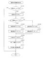
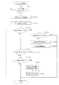
ステップS506では、新たに特別変動保留エリアに記憶された当否乱数カウンタC1の値が大当たりや小当たりに対応する値であるか否かを判別する当否判定処理を行う。尚、当否判定処理の詳細については後述する。 In step S506, a win/loss determination process is performed to determine whether or not the value of the win/loss random number counter C1 newly stored in the special variation holding area is a value corresponding to a big hit or a small hit. The details of the hit/miss determination processing will be described later.
続くステップS507では、ステップS506で当否乱数カウンタC1の値が大当たりに対応する値であると判定された場合に、新たに特別変動保留エリアに記憶された種別決定カウンタC2の値に基づいて、大当たりの種別を判別する種別判定処理を行う。尚、種別判定処理の詳細については後述する。 In the following step S507, when it is determined in step S506 that the value of the winning/discarding random number counter C1 corresponds to the jackpot, the jackpot is determined based on the value of the type determination counter C2 newly stored in the special variation suspension area. A type determination process for determining the type of is performed. The details of the type determination process will be described later.
続くステップS508では、ステップS506で当否乱数カウンタC1の値が大当たりに対応する値ではないと判定された場合に、新たに特別変動保留エリアに記憶された変動選択カウンタC3の値に基づいて、外れ変動時のリーチの種別を判別するリーチ判定処理を行う。尚、リーチ判定処理の詳細については後述する。 In the following step S508, when it is determined in step S506 that the value of the winning/discarding random number counter C1 is not the value corresponding to the big hit, the value is deviated based on the value of the fluctuation selection counter C3 newly stored in the special fluctuation holding area. Reach determination processing for determining the type of reach at the time of fluctuation is performed. The details of the reach determination process will be described later.
ここで、ステップS506の当否判定処理の詳細について、図14を参照して説明する。 Here, details of the hit/miss determination processing in step S506 will be described with reference to FIG.
先ず、ステップS5101では、新たに特別変動保留エリアに記憶された当否乱数カウンタC1の値が、第1当否判定テーブルに記憶された値である「7」、「307」のどちらかと一致するか否かを判別する。ちなみに、「7」、「307」は、低確率状態でも、高確率状態でも大当たりとなる値である。 First, in step S5101, it is determined whether or not the value of the winning/discarding random number counter C1 newly stored in the special fluctuation holding area matches either "7" or "307" which is the value stored in the first winning/discarding determination table. Determine whether. By the way, "7" and "307" are values that are a big hit in both the low-probability state and the high-probability state.
尚、図14では便宜上、当該ステップS5101の処理を簡略化して記載しているが、実際には、当否乱数カウンタC1の値が「7」であるか否かを判別するとともに、当該判別で否定判別された場合には、当否乱数カウンタC1の値が「307」であるか否かを判別し、これらどちらかの判別で肯定判別された場合に、当該ステップS5101で肯定判別され、どちらの判別においても否定判別された場合に、当該ステップS5101で否定判別されることとなる。 Note that, in FIG. 14, the process of step S 5101 is simplified for convenience of description, but actually, it is determined whether or not the value of the random number counter C1 is “7”, and the determination is negative. If it is determined, it is determined whether or not the value of the random number counter C1 is "307", and if either of these determinations is affirmative, affirmative determination is made in step S5101, which determination is which? Also in case of negative determination, the negative determination is made in step S 5101.
ステップS5101で肯定判別された場合には、ステップS5102において、第1当否フラグをオンにした後、本処理を終了する。一方、ステップS5101で否定判別された場合には、ステップS5103において、新たに特別変動保留エリアに記憶された当否乱数カウンタC1の値が第2当否判定テーブルに記憶された値である「8〜11、308〜311」のいずれかであるか否かを判別する。ちなみに、「8〜11、308〜311」は、高確率状態(確変モード)でのみ大当たりとなる値である。尚、当該判別処理に際しても、実際には、上記のように当否乱数カウンタC1の値と大当たりに対応する各値とが一致するか否かを1つずつ判別する。 If an affirmative decision is made in step S5101, then in step S5102, the first winning/prohibiting flag is turned on, and then this processing ends. On the other hand, when a negative determination is made in step S5101, the value of the win/loss random number counter C1 newly stored in the special variation holding area in step S5103 is the value stored in the second win/loss determination table “8 to 11”. , 308-311”. By the way, "8-11, 308-311" is a value that is a big hit only in the high probability state (probability variation mode). Even in the determination process, in reality, as described above, it is determined whether or not the value of the random number counter C1 and the respective values corresponding to the jackpot match.
ステップS5103で肯定判別された場合には、ステップS5104において第2当否フラグをオンにした後、本処理を終了する。一方、ステップS5103で否定判別された場合、すなわち、高確率状態でも「外れ」となる場合には、ステップS5105において、新たに変動情報が記憶されたのが第2特別変動保留エリアであるか(第2変動表示に対応しているか)否かを判別する。ステップS5105で肯定判別された場合には、ステップS5106において、に新たに特別変動保留エリアに記憶された当否乱数カウンタC1の値が、小当たり判定テーブルに記憶された値である「101〜210」と一致するか否かを判別する。 If an affirmative decision is made in step S5103, then in step S5104 the second hit/miss flag is turned on and then this processing ends. On the other hand, if a negative determination is made in step S5103, that is, if the high probability state is also “displaced”, in step S5105, whether the new variation information is stored is the second special variation suspension area ( Whether the second variable display is supported or not) is determined. If an affirmative decision is made in step S5105, the value of the random number counter C1 newly stored in the special fluctuation holding area in step S5106 is the value "101-210" stored in the small hitting determination table. It is determined whether or not
ステップS5106で肯定判別された場合には、ステップS5107において小当たりフラグをオンにした後、本処理を終了する。一方、ステップS5106で否定判別された場合には、そのまま本処理を終了する。尚、本実施形態では、第1当否フラグ、第2当否フラグ、及び、小当たりフラグは、特別変動保留エリアの対応する保留エリアの当否乱数記憶エリアに対し、第1当否フラグ、第2当否フラグ、及び、小当たりフラグに相当する情報を上書きすることで、第1当否フラグ、第2当否フラグ、及び、小当たりフラグをオンした状態となるように構成されている。 If an affirmative decision is made in step S5106, the small hit flag is turned on in step S5107, and then this processing ends. On the other hand, if a negative decision is made in step S5106, the present process is terminated. In the present embodiment, the first win/fail flag, the second win/fail flag, and the small hit flag are the first win/fail flag and the second win/fail flag for the win/fail random number storage area of the corresponding holding area of the special variation hold area. By overwriting the information corresponding to the small hit flag, the first hit/miss flag, the second hit/miss flag, and the small hit flag are turned on.
また、ステップS5105で否定判別された場合には、そのまま本処理を終了する。すなわち、第1始動入賞装置33aへの遊技球の入球に基づいて行われる当否抽選では、小当たりに当選する可能性がないように構成されている。尚、第1始動入賞装置33aへの入球に基づく当否抽選でも(第2始動入賞装置33bへの入球に基づく当否抽選における小当たりの当選確率よりも低確率で)小当たりに当選する場合があるように構成してもよい。
If a negative decision is made in step S5105, this processing is ended as it is. That is, in the winning/winning lottery performed based on the entry of the game balls into the first
次に、ステップS507の第2種別判定処理について、図15(b)を参照して説明する。先ず、ステップS5301では、直前に行われた当否判定処理にて、第1又は第2当否フラグがオン設定されたか否かを判別する。ステップS5301で否定判別された(大当たり状態が発生する可能性がない)場合には、そのまま本処理を終了する。 Next, the second type determination process of step S507 will be described with reference to FIG. First, in step S5301, it is determined whether or not the first or second win/loss flag has been set to ON in the win/loss determination process performed immediately before. If a negative determination is made in step S5301 (there is no possibility that a big hit state will occur), this processing is ended as it is.
一方、ステップS5301で肯定判別された(大当たり状態の発生する可能性がある)場合には、ステップS5302において、第2種別判定テーブルを参酌し、新たに特別変動保留エリアに記憶された種別決定カウンタC2の値が、「10RS」に対応する値「14〜19」と一致するか否かを判別する。ステップS5302で肯定判別された場合には、ステップS5303において、10RSフラグをオンにしてから、本処理を終了する。 On the other hand, if an affirmative determination is made in step S5301 (a big hit state may occur), in step S5302, the second type determination table is taken into consideration, and the type determination counter newly stored in the special variation suspension area is taken into consideration. It is determined whether or not the value of C2 matches the value “14 to 19” corresponding to “10RS”. If an affirmative decision is made in step S5302, then in step S5303, the 10RS flag is turned on, and then this processing is ended.
一方、ステップS5302で否定判別された場合には、ステップS5304において、第2種別判定テーブルを参酌し、新たに特別変動保留エリアに記憶された種別決定カウンタC2の値が、「4RS」に対応する値「8〜13」と一致するか否かを判別する。ステップS5304で肯定判別された場合には、ステップS5305において4RSフラグをオンにしてから、本処理を終了する。 On the other hand, when a negative determination is made in step S5302, in step S5304, the value of the type determination counter C2 newly stored in the special variation holding area corresponds to “4RS” by referring to the second type determination table. It is determined whether or not it matches the value “8 to 13”. If an affirmative decision is made in step S5304, the 4RS flag is turned on in step S5305, and then this processing ends.
一方、ステップS5304で否定判別された場合には、ステップS5306において、10RNフラグをオンにしてから、本処理を終了する。尚、本実施形態では、10RSフラグ、4RSフラグ、及び、10RNフラグは、特別変動保留エリアの対応する保留エリアの当選種別乱数記憶エリアに対し、第1当否フラグ、第2当否フラグ、及び、小当たりフラグに相当する情報を上書きすることで、10RSフラグ、4RSフラグ、及び、10RNフラグをオンした状態となるように構成されている。 On the other hand, if a negative decision is made in step S5304, then in step S5306, the 10RN flag is turned on, and then this processing is ended. In the present embodiment, the 10RS flag, the 4RS flag, and the 10RN flag are the first winning/disabling flag, the second winning/disabling flag, and the small value with respect to the winning type random number storage area of the corresponding holding area of the special variation holding area. By overwriting the information corresponding to the hit flag, the 10RS flag, the 4RS flag, and the 10RN flag are turned on.
次に、ステップS508のリーチ判定処理について、図16を参照して説明する。先ず、ステップS5401では、直前に行われた当否判定処理にて、第1当否フラグが設定されたか否かを判別する。ステップS5401で肯定判別された場合、すなわち、低確率状態及び高確率状態のどちらにおいても大当たりとなる(必ず大当たり状態が発生する)場合には、そのまま本処理を終了する。 Next, the reach determination process of step S508 will be described with reference to FIG. First, in step S5401, it is determined whether or not the first win/loss flag has been set in the win/loss determination process performed immediately before. If an affirmative decision is made in step S5401, that is, if the jackpot is a jackpot in both the low-probability state and the high-probability state (the jackpot state always occurs), this processing is ended.
一方、ステップS5401で否定判別された場合、すなわち、少なくとも低確率状態においては大当たり状態が発生しない(外れとなる可能性がある)場合には、ステップS5402において、リーチ判定テーブルを参酌し、新たに特別変動保留エリアに記憶された変動選択カウンタC3の値が、「前後外れリーチ」に対応する値「0、1」のどちらかと一致するか否かを判別する。ステップS5402で肯定判別された場合には、ステップS5403において、前後外れリーチの発生を示す前後フラグをオンにした後、本処理を終了する。 On the other hand, if a negative determination is made in step S5401, that is, if the jackpot state does not occur (there is a possibility of being out of place) at least in the low-probability state, then in step S5402, the reach determination table is taken into consideration and newly added. It is determined whether or not the value of the fluctuation selection counter C3 stored in the special fluctuation holding area matches any one of the values "0, 1" corresponding to the "out-of-position reach". If an affirmative decision is made in step S5402, then in step S5403, the front/rear flag indicating the occurrence of front/rear deviation is turned on, and then this processing is ended.
一方、ステップS5402で否定判別された場合には、ステップS5404において、リーチ判定テーブルを参酌し、新たに特別変動保留エリアに記憶された変動選択カウンタC3の値が、「前後外れ以外リーチ」に対応する値「2〜21」のいずれかと一致するか否かを判別する。当該ステップS5404で肯定判別された場合には、ステップS5405において前後以外フラグをオンにした後、本処理を終了する。 On the other hand, if a negative decision is made in step S5402, then in step S5404, the reach determination table is taken into consideration, and the value of the variation selection counter C3 newly stored in the special variation holding area corresponds to “reach other than front/back deviation”. It is determined whether or not any of the values “2 to 21” to be performed matches. If an affirmative decision is made in step S5404, the flags other than before and after are turned on in step S5405, and then the present process ends.
また、ステップS5404で否定判別された場合、すなわち、リーチ状態を経ることなく変動表示が終了する「完全外れ」となる場合には、そのまま本処理を終了する。 If a negative determination is made in step S5404, that is, if the variable display ends without reaching the reach state, that is, “complete disconnection”, this processing ends.
図13の説明に戻り、ステップS508に続くステップS509では、先発コマンドの設定処理を行う。尚、先発コマンドには、当否判定処理、種別判定処理、及びリーチ判定処理の結果を示す変動情報(変動表示の内容を決定するために使用される情報)や、第1始動入賞装置33a又は第2始動入賞装置33bのどちらへの入球を契機とする変動情報であるのかを示す情報が含まれ、次回の外部出力処理(ステップS201参照)にてサブ制御装置262に出力される。
Returning to the description of FIG. 13, in step S509 subsequent to step S508, the advance command setting process is performed. The start command includes variation information (information used to determine the content of the variation display) indicating the results of the hit/miss determination processing, the type determination processing, and the reach determination processing, the first
ステップS509の処理の後、又は、ステップS501、或いは、ステップS502で否定判別された場合には、ステップS510において、遊技球が第1始動入賞装置33に入賞したか否かを第1始動入賞スイッチ224aの検知情報により判別する。当該ステップS510で否定判別された場合には、そのまま本処理を終了する。一方、肯定判別された場合には、ステップS511において、第1始動入賞装置33aへの入賞を契機とする変動表示の保留数をカウントする第1保留カウンタNaの値が上限値(本実施形態では「4」)未満であるか否かを判別する。当該ステップS511で否定判別された場合には、そのまま本処理を終了する。一方、ステップS511で肯定判別された場合には、ステップS512に進み、第1保留カウンタNaを1インクメントする。
After the processing of step S509, or if the determination in step S501 or step S502 is negative, it is determined in step S510 whether or not the game ball has won the first starting prize device 33. It is determined by the detection information of 224a. When a negative determination is made in step S510, this processing ends as it is. On the other hand, if the determination is affirmative, in step S511, the value of the first suspension counter Na that counts the number of suspensions of variable display triggered by the winning of the first
続くステップS513では、第1変動表示の保留数が1つ増えたことに対応する第1保留表示装置46a(第1保留ランプ)の加算表示処理を行う。つまり、左右一対の第1保留ランプが両方とも消灯状態であった場合には左側の第1保留ランプを点灯させ、左側の第1保留ランプが点灯状態であり右側の第1保留ランプが消灯状態であった場合には左右両方の第1保留ランプを点灯させ、左右両方の第1保留ランプが点灯状態であった場合には右側の第1保留ランプを点灯させたまま左側の第1保留ランプを点滅させ、左側の第1保留ランプが点滅状態であり右側の第1保留ランプが点灯状態であった場合には左右両方の第1保留ランプを点滅させるための処理を行う。 In a succeeding step S513, addition display processing of the first hold display device 46a (first hold lamp) corresponding to the increase in the number of hold of the first variable display by 1 is performed. That is, when both the pair of left and right first holding lamps are off, the left first holding lamp is turned on, the left first holding lamp is on, and the right first holding lamp is off. If it is, both the left and right first holding lamps are turned on. If both the left and right first holding lamps are turned on, the left first holding lamp is turned on while the right first holding lamp is turned on. When the first holding lamp on the left side is in the blinking state and the first holding lamp on the right side is in the lighting state, processing for blinking both the left and right first holding lamps is performed.
ステップS513の後、ステップS514において、当否乱数カウンタC1、種別決定カウンタC2、変動選択カウンタC3の各値を、第1特別変動保留エリアの空いている保留エリア(当否乱数記憶エリア、当選種別乱数記憶エリア、リーチ乱数記憶エリア)に格納する。ステップS514の後、ステップS515に移行する。 After step S513, in step S514, the respective values of the winning/discarding random number counter C1, the type determining counter C2, and the fluctuation selecting counter C3 are stored in the vacant holding areas of the first special fluctuation holding area (the winning/failing random number storage area and the winning type random number storage). Area, reach random number storage area). After step S514, the process proceeds to step S515.
ステップS515では、新たに特別変動保留エリアに記憶された当否乱数カウンタC1の値が大当たりに対応する値であるか否かを判別する当否判定処理を行う。当否判定処理の詳細については上述している。 In step S515, a win/loss determination process is performed to determine whether or not the value of the win/loss random number counter C1 newly stored in the special variation holding area is a value corresponding to the jackpot. The details of the hit/miss determination processing have been described above.
続くステップS516では、ステップS513で当否乱数カウンタC1の値が大当たりに対応する値であると判定された場合に、新たに特別変動保留エリアに記憶された種別決定カウンタC2の値に基づいて、大当たり種別を判別する第1種別判定処理を行う。 In the following step S516, when it is determined in step S513 that the value of the random number counter C1 is a value corresponding to the jackpot, the jackpot is determined based on the value of the type determination counter C2 newly stored in the special fluctuation suspension area. A first type determination process for determining the type is performed.
ここで、ステップS516の第1種別判定処理について、図15(a)を参照して説明する。先ず、ステップS5201では、直前に行われた当否判定処理にて、第1又は第2当否フラグがオン設定されたか否かを判別する。ステップS5201で否定判別された(大当たり状態の発生する可能性がない)場合には、そのまま本処理を終了する。 Here, the first type determination processing of step S516 will be described with reference to FIG. First, in step S5201, it is determined whether or not the first or second win/loss flag is set to ON in the win/loss determination process performed immediately before. When a negative determination is made in step S5201 (there is no possibility that a big hit state will occur), this processing is ended as it is.
一方、ステップS5201で肯定判別された(大当たり状態の発生する可能性がある)場合には、ステップS5202において、第1種別判定テーブルを参酌し、新たに特別変動保留エリアに記憶された種別決定カウンタC2の値が、「10RS」に対応する値「19」と一致するか否かを判別する。ステップS5202で肯定判別された場合には、ステップS5203において10RSフラグをオンにしてから、本処理を終了する。 On the other hand, if an affirmative determination is made in step S5201 (a big hit state may occur), in step S5202, the type determination counter newly stored in the special variation suspension area is taken into consideration by referring to the first type determination table. It is determined whether or not the value of C2 matches the value “19” corresponding to “10RS”. If an affirmative decision is made in step S5202, the 10RS flag is turned on in step S5203, and then this processing ends.
一方、ステップS5202で否定判別された場合には、ステップS5204において、種別判定テーブルを参酌し、新たに特別変動保留エリアに記憶された種別決定カウンタC2の値が「4RS」に対応する値「8〜18」と一致するか否かを判別する。ステップS5204で肯定判別された場合には、ステップS5205において、4RSフラグをオンにしてから、本処理を終了する。 On the other hand, when a negative determination is made in step S5202, in step S5204, the type determination table is taken into consideration, and the value of the type determination counter C2 newly stored in the special variation suspension area is the value “8RS” corresponding to “4RS”. .About.18". If an affirmative decision is made in step S5204, then in step S5205 the 4RS flag is turned on and then this processing is ended.
また、ステップS5204で否定判別された場合には、ステップS5206において、10RNフラグをオンにしてから、本処理を終了する。尚、本実施形態では、第1始動入賞装置33a又は第2始動入賞装置33bのどちらへの入球を契機として大当たり状態に当選した場合であっても、高確率状態が付与される割合は同じである。但し、第1始動入賞装置33aへの入球を契機として大当たり状態に当選した場合には、「10RS」に当選する割合が5%、「4RS」に当選する割合が55%(「10RN」に当選する割合が40%)であるのに対し、第2始動入賞装置33bへの入球を契機として大当たり状態に当選した場合には、「10RS」に当選する割合が30%、「4RS」に当選する割合が30%(「10RN」に当選する割合が40%)である。
If a negative decision is made in step S5204, the 10RN flag is turned on in step S5206, and then the present process is terminated. In the present embodiment, regardless of whether the first
図13の説明に戻り、ステップS516に続くステップS517では、ステップS515で当否乱数カウンタC1の値が大当たりに対応する値ではないと判定された場合に、新たに特別変動保留エリアに記憶された変動選択カウンタC3の値に基づいて、リーチの種別を判別するリーチ判定処理を行う。リーチ判定処理(図16参照)の詳細については上述している。 Returning to the explanation of FIG. 13, in step S517 following step S516, when it is determined in step S515 that the value of the random number counter C1 is not the value corresponding to the jackpot, the fluctuation newly stored in the special fluctuation holding area is changed. Reach determination processing for determining the type of reach is performed based on the value of the selection counter C3. The details of the reach determination processing (see FIG. 16) have been described above.
ステップS517の後、ステップS518において、先発コマンドの設定処理を行い、本処理を終了する。尚、本実施形態では、第1始動入賞装置33a又は第2始動入賞装置33bに遊技球が入球すると、当否乱数カウンタC1の値等が直接特別変動保留エリアに記憶され、その後、当否判定処理、種別判定処理、及びリーチ判定処理が実行される構成となっているが、特にこのような構成に限定されるものではない。例えば、当否乱数カウンタC1の値等を取得した際にこれらのカウンタ値を一時的に記憶する仮記憶エリアを設け、当該仮記憶エリアに記憶された情報に関し、当否判定処理、種別判定処理、及びリーチ判定処理を実行した後、対応する特別変動保留エリアの保留エリアに記憶する構成を採用してもよい。
After step S517, the advance command setting process is performed in step S518, and this process ends. In the present embodiment, when a game ball enters the first
尚、ステップS505、ステップS514の当否乱数カウンタC1の値を抽出する処理が判別値抽出処理を構成し、同じくステップS505、ステップS514の抽出した当否乱数カウンタC1の値を特別変動保留エリアに記憶する処理が判別値格納処理を構成し、当該処理を行う機能が当否関連情報取得手段に相当する。さらに、当否乱数カウンタC1の値を抽出し、記憶する機能が情報取得手段を構成する。また、ステップS506、ステップS515(ステップS5101、ステップS5103)の当否乱数カウンタC1の値が当選に対応する値であるか否かを判別する処理が第1当否判別処理を構成し、その判別結果を記憶する(対応フラグをセットする)ステップS5102、ステップS5104の処理が結果記憶処理を構成する。 The process of extracting the value of the winning/discarding random number counter C1 in steps S505 and S514 constitutes a discriminant value extracting process, and the value of the winning/discarding random number counter C1 extracted in steps S505 and S514 is stored in the special fluctuation holding area. The process constitutes the discriminant value storage process, and the function of performing the process corresponds to the hit/failure related information acquisition means. Further, the function of extracting and storing the value of the random number counter C1 constitutes the information acquisition means. Further, the process of determining whether or not the value of the winning/discarding random number counter C1 in steps S506 and S515 (steps S5101, S5103) is a value corresponding to the winning constitutes a first winning/discarding process, and the determination result is The process of storing (setting the corresponding flag) steps S5102 and S5104 constitutes a result storing process.
次に、ステップS305のスルーゲート通過処理について図17のフローチャートを参照して説明する。ステップS601では、遊技球がスルーゲート34を通過したか否かをスルーゲートスイッチ225の検知情報により判別する。ステップS601で否定判別された場合、そのまま本処理を終了する。
Next, the through gate passage processing of step S305 will be described with reference to the flowchart of FIG. In step S601, whether or not the game ball has passed through the through
一方、ステップS601にて肯定判別された場合、すなわち、遊技球がスルーゲート34を通過したと判別されると、ステップS602において、普通図柄表示装置41にて行われる変動表示の保留数をカウントする普通保留カウンタNcの値が上限値(本実施形態では4)未満であるか否かを判別する。ここで否定判別された場合には、そのまま本処理を終了する。一方、ステップS602で肯定判別された場合、すなわち、スルーゲート34への遊技球の通過が確認され、且つ、普通保留カウンタNcの値<4であることを条件にステップS603に進み、普通保留カウンタNcを1インクリメントする。
On the other hand, if the affirmative determination is made in step S601, that is, if it is determined that the game ball has passed through the through
また、続くステップS604では、普通図柄表示装置41における変動表示の保留数が1つ増えたことに対応する普通保留表示装置44(普通保留ランプ406)の加算表示処理を行う。つまり、左右一対の普通保留ランプ406が両方とも消灯状態であった場合には左側の普通保留ランプ406を点灯させ、左側の普通保留ランプ406が点灯状態であり右側の普通保留ランプ406が消灯状態であった場合には左右両方の普通保留ランプ406を点灯させ、左右両方の普通保留ランプ406が点灯状態であった場合には右側の普通保留ランプ406を点灯させたまま左側の普通保留ランプ406を点滅させ、左側の普通保留ランプ406が点滅状態であり右側の普通保留ランプ406が点灯状態であった場合には左右両方の普通保留ランプ406を点滅させるための処理を行う。
Further, in the subsequent step S604, addition display processing of the normal hold display device 44 (normal hold lamp 406) corresponding to the fact that the number of variable displays held in the normal
ステップS604の後、ステップS605において、当否に関わる乱数を取得する。具体的には、上記ステップS303の乱数更新処理で更新した普通図柄乱数カウンタC4の値を、RAM503の普通変動保留エリアの空き記憶エリアのうち最初のエリアに格納する。その後、スルーゲート通過処理を終了する。
After step S604, in step S605, a random number related to the success or failure is acquired. Specifically, the value of the normal symbol random number counter C4 updated in the random number updating process of step S303 is stored in the first free storage area of the normal fluctuation holding area of the
次に、ステップS306の発射許可コマンド設定処理について、図18を参照して説明する。 Next, the firing permission command setting process of step S306 will be described with reference to FIG.
先ず、ステップS701では、発射制御回路312から発射状態信号を受信している状態であることを示す発射許可フラグがオン設定されているか否かを判別する。尚、発射状態信号は、発射制御回路312が、ハンドル18からのタッチ信号、及び、発射スイッチ信号と、払出制御装置311からのCRユニット接続信号とを受信している場合に、発射制御回路312から主制御装置261に送信されるようになっている。
First, in step S701, it is determined whether or not the firing permission flag indicating that the firing state signal is being received from the firing
ステップS701で肯定判別された場合には、ステップS702において、発射状態信号を受信しているか否かを判別する。ステップS702で否定判別された場合、ステップS703において、発射許可フラグをオフしてから、本処理を終了する。 When an affirmative determination is made in step S701, it is determined in step S702 whether or not a firing state signal has been received. When a negative determination is made in step S702, the firing permission flag is turned off in step S703, and then this processing ends.
一方、ステップS702で肯定判別された場合には、ステップS704において、遊技球の発射間隔を計るために使用される発射タイマの値が「0」であるか否かを判別する。ステップS704で否定判別された場合には、ステップS707において、発射タイマの値を1減算してから、本処理を終了する。 On the other hand, if an affirmative decision is made in step S702, then in a step S704 it is decided whether or not the value of the firing timer used for measuring the firing interval of the game ball is "0". When a negative determination is made in step S704, the value of the firing timer is decremented by 1 in step S707, and then this processing ends.
一方、ステップS704で肯定判別された場合には、ステップS705において、主制御装置261から、発射制御回路312に対して発射許可信号を送信する。続くステップS706では、発射許可フラグをオフする。ステップS706の後、本処理を終了する。
On the other hand, if an affirmative decision is made in step S704, then in step S705, the
また、ステップS701で否定判別された場合には、ステップS708において、発射状態信号を受信しているか否かを判別する。ステップS708で否定判別された場合には、そのまま本処理を終了する。一方、ステップS708で肯定判別された場合には、ステップS709において、発射許可フラグをオン設定する。 In addition, when the determination in step S701 is negative, it is determined in step S708 whether or not the firing state signal is received. When a negative determination is made in step S708, this processing is ended as it is. On the other hand, if an affirmative decision is made in step S708, then in step S709 the firing permission flag is set ON.
続くステップS710では、発射制御回路312に対して球送り信号を送信する。さらに、ステップS711において、発射タイマに対して0.6秒に相当する「300」を設定する。これにより、球送り装置63により遊技球が発射位置に確実にセットされてから、遊技球が発射装置60により打出されるように構成されるとともに、主制御装置261が発射制御回路312から発射状態信号を受信し続けている状態において、主制御装置261から発射許可信号が0.6秒間隔で送信され、0.6秒間隔で遊技球が発射装置60により発射されるようになっている。ステップS711の後、本処理を終了する。
In a succeeding step S710, a ball sending signal is transmitted to the
尚、発射制御回路312では、主制御装置261から発射許可信号を受信した場合に、ハンドル18、及び、払出制御装置311から、タッチ信号、発射スイッチ信号、及び、CRユニット接続信号の全てを受信しているか否かを判別し、肯定判別された場合に、発射装置60(発射ソレノイド)を駆動させ、遊技球を発射させるための発射処理が行われるようになっている。尚、発射制御回路312は、ダイヤル位置信号に基づいて、遊技球の発射強さ(発射速度)に関する発射装置60の調節制御を行う。これにより、遊技球が、調節された強さで発射装置60により打ち出されるようになっている。
When the
また、発射制御回路312は、主制御装置261から球送り信号を受信した場合に、発射レール61のうち発射装置60にて遊技球が発射されることとなる発射位置に遊技球がセットされていることを検知する準備球検知センサを確認し、発射位置に遊技球がセットされていないことが確認された場合には、球送り装置63を駆動させ、遊技球を発射位置にセットするための球送り処理を行う。
In addition, when the ball control signal is received from the
図12は、NMI割込み処理を示すフローチャートであり、本処理は、主制御装置261のCPU501により停電の発生等によるパチンコ機10の電源断時に実行される。このNMI割込みにより、電源断時の主制御装置261の状態がRAM503のバックアップエリア503aに記憶される。
FIG. 12 is a flowchart showing the NMI interrupt processing, and this processing is executed by the CPU 501 of the
すなわち、停電の発生等によりパチンコ機10の電源が遮断されると、停電信号SK1が停電監視回路542から主制御装置261内のCPU501のNMI端子に出力される。すると、CPU501は実行中の制御を中断してNMI割込み処理を開始し、ステップS401において、電源断の発生情報の設定として電源断の発生情報をRAM503のバックアップエリア503aに記憶してNMI割込み処理を終了する。
That is, when the power of the
なお、上記のNMI割込み処理は払出制御装置311でも同様に実行され、かかるNMI割込みにより、電源断の発生情報がRAM513のバックアップエリア513aに記憶される。すなわち、停電の発生等によりパチンコ機10の電源が遮断されると、停電信号SK1が停電監視回路542から払出制御装置311内のCPU511のNMI端子に出力され、CPU511は実行中の制御を中断して図12のNMI割込み処理を開始する。その内容は上記説明の通りである。
Note that the NMI interrupt processing described above is also executed in the
次に、主制御装置261内のCPU501により実行されるメイン処理の流れを図9のフローチャートを参照しながら説明する。このメイン処理は電源投入時のリセットに伴い起動される。
Next, the flow of main processing executed by the CPU 501 in the
先ず、ステップS101では、電源投入に伴う初期設定処理を実行する。具体的には、スタックポインタに予め決められた所定値を設定すると共に、サブ側の制御装置(サブ制御装置262,払出制御装置311等)が動作可能な状態になるのを待つために例えば1秒程度、ウェイト処理を実行する。続くステップS102では、RAMアクセスを許可する。
First, in step S101, an initialization process associated with power-on is executed. Specifically, for example, in order to set the stack pointer to a predetermined value and wait for the sub-side control devices (
その後、CPU501内のRAM503に関してデータバックアップの処理を実行する。つまり、ステップS103では、電源・発射制御装置310の電源回路313に設けたRAM消去スイッチ323が押下(ON)されているか否かを判別し、押下されていれば、バックアップデータをクリア(消去)するべく、ステップS112へ移行する。一方、RAM消去スイッチ323が押下されていなければ、続くステップS104で、RAM503のバックアップエリア503aに電源断の発生情報が設定されているか否かを判別する。ここで、設定されていなければ、バックアップデータは記憶されていないので、この場合もステップS112へ移行する。バックアップエリア503aに電源断の発生情報が設定されていれば、ステップS105でRAM判定値を算出し、続くステップS106では、そのRAM判定値が電源断時に保存したRAM判定値と一致するか否か、すなわちバックアップの有効性を判別する。ここで算出したRAM判定値が電源断時に保存したRAM判定値と一致しなければ、バックアップされたデータは破壊されているので、この場合もステップS112へ移行する。
After that, the data backup processing is executed for the
ステップS112の処理では、サブ制御装置262及び払出制御装置311等を初期化するために、初期化コマンドを送信する。その後、RAMの初期化処理(ステップS113等)に移行する。なお、RAM判定値は、例えばRAM503の作業領域アドレスにおけるチェックサム値である。このRAM判定値に代えて、RAM503の所定のエリアに書き込まれたキーワードが正しく保存されているか否かによりバックアップの有効性を判断することも可能である。
In the process of step S112, an initialization command is transmitted to initialize the
上述したように、本パチンコ機10では、例えばホールの営業開始時など、電源投入時に初期状態に戻したい場合にはRAM消去スイッチ323を押しながら電源が投入される。従って、RAM消去スイッチ323がONされていれば、RAMの初期化処理(ステップS113等)に移行する。また、電源断の発生情報が設定されていない場合や、RAM判定値(チェックサム値等)によりバックアップの異常が確認された場合も同様にRAM503の初期化処理(ステップS113等)に移行する。つまり、ステップS113ではRAM503の使用領域を0にクリアし、続くステップS114ではRAM503の初期値を設定する。その後、ステップS111で割込み許可を設定し、後述する通常処理に移行する。
As described above, in the
一方、RAM消去スイッチ323が押されていない場合(ステップS103:NO)には、電源断の発生情報が設定されていること、及びRAM判定値(チェックサム値等)が正常であることを条件に、復電時の処理(電源断復旧時の処理)を実行する。つまり、ステップS107では、電源断前のスタックポインタを復帰させ、ステップS108では、電源断の発生情報をクリアする。
On the other hand, when the
ステップS109では、サブ側の制御装置を電源断時の遊技状態に復帰させるコマンドを送信する。ステップS110では、使用レジスタをRAM503のバックアップエリア503aから復帰させる。その後、ステップS111で割込み許可を設定し、後述する通常処理に移行する。
In step S109, a command for returning the control device on the sub side to the game state when the power is turned off is transmitted. In step S110, the used register is restored from the
次に、通常処理の流れを図10のフローチャートを参照しながら説明する。この通常処理では遊技の主要な処理が実行される。その概要として、ステップS201〜S210の処理が4msec周期の定期処理として実行され、その残余時間でステップS211,ステップS212のカウンタ更新処理が実行される構成となっている。 Next, the flow of normal processing will be described with reference to the flowchart of FIG. In this normal processing, the main processing of the game is executed. As an outline thereof, the processing of steps S201 to S210 is executed as a regular processing of a 4 msec cycle, and the counter updating processing of steps S211 and S212 is executed in the remaining time.
先ずステップS201では、前回の通常処理で更新された特別表示装置43a、43bや始動入賞装置33等の設定内容に基づいた制御信号を各装置に送信したり、コマンド等の出力データをサブ側の各制御装置に送信したりする外部出力処理を実行する。
First, in step S201, a control signal based on the setting contents of the
例えば、装飾図柄表示装置42による装飾図柄の変動表示に際して、変動パターンコマンド、図柄コマンド等をサブ制御装置262に送信する。つまり、変動パターンコマンドや図柄コマンドは、第1及び第2特別表示装置43a、43bにて行われる表示に合わせた表示演出を装飾図柄表示装置42にて行わせるためにサブ制御装置262に出力されるコマンドである。これに対し、変動パターンコマンド、図柄コマンド等を入力したサブ制御装置262は、かかる各種コマンドに基づいて、装飾図柄表示装置42の変動態様(変動時間や演出態様など)を決定し、該変動態様を装飾図柄表示装置42において表示(変動表示)するように表示制御装置45に対し指示を出す。
For example, when the decorative pattern is displayed on the decorative
変動パターンコマンドには、ノーマルリーチ、スーパーリーチ、プレミアムリーチといった装飾図柄の変動種別を特定する情報が含まれている。一方、サブ制御装置262には、これらの変動パターンコマンドと装飾図柄の変動種別との関係がテーブルで記憶されている。そして、サブ制御装置262は、変動パターンコマンドに基づいて、変動表示の演出パターン等を決定し、表示制御装置45や音声等の制御を行う。
The variation pattern command includes information for identifying the variation type of the decorative design such as normal reach, super reach, and premium reach. On the other hand, the
ここで、装飾図柄の変動種別について説明する。「ノーマルリーチ」は、装飾図柄の変動以外には特段の演出表示がされないリーチパターンである。尚、確変モード時及び時間短縮モード時においては、各種リーチとなる場合においても、通常モード時に比べ、変動表示時間が短縮されている。例えば、ノーマルリーチが導出される変動表示の時間(変動時間)は、通常モード時時には「12秒」、又は、「15秒」、確変モード時及び時間短縮モード時には「9秒」、又は、「12秒」となっている。尚、通常モードにおいても、第1変動表示が4つ保留されている状態から開始される第1変動表示についても、一時的な時間短縮状態となり、該第1変動表示の変動時間がノーマルリーチであれば「9秒」、又は、「12秒」に設定される。 Here, the variation type of the decorative pattern will be described. “Normal reach” is a reach pattern in which no special effect display is displayed other than the variation of the decorative pattern. In the probability variation mode and the time reduction mode, the variation display time is shorter than that in the normal mode even in the case of various types of reach. For example, the variation display time (variation time) from which the normal reach is derived is “12 seconds” or “15 seconds” in the normal mode, “9 seconds” in the probability variation mode and the time reduction mode, or “12”. Seconds”. In the normal mode as well, the first variation display that starts from the state where four first variation displays are suspended is also in a temporarily shortened state, and the variation time of the first variation display is normal reach. For example, it is set to "9 seconds" or "12 seconds".
「スーパーリーチ」は、装飾図柄の変動表示中(リーチ状態成立後)において、装飾図柄以外にも、装飾図柄表示装置42にキャラクタ等が表示され、これにより遊技者に対し期待感を抱かせるリーチパターンである。本実施形態では、スーパーリーチが導出される変動表示の変動時間は、通常モード時時には「13秒」、「16秒」、「20秒」、「25秒」、又は、「30秒」、確変モード時及び時間短縮モード時には「13秒」、「16秒」、「20秒」、「22秒」、「25秒」、「27秒」、又は、「30秒」となっている。尚、スーパーリーチが発生する場合の変動表示の変動時間はいずれの遊技モードにおいても共通の変動時間となるように構成してもよい。
"Super reach" is a reach that makes the player have an expectation by displaying characters other than the decorative pattern on the decorative
「プレミアムリーチ」は、大当たり状態が発生する際にのみ導出され得る演出態様であり、装飾図柄の変動表示中(リーチ状態成立後)において、装飾図柄以外に、スーパーリーチとは異なるパターンのキャラクタ等が表示される態様で行われ、これにより遊技者に対し期待感を抱かせるリーチパターンである。本実施形態のプレミアムリーチが導出される変動表示は、スーパーリーチが導出される変動表示よりも変動時間が長く、また、高入球状態及び低入球状態のどちらの状態においても同じ長さ(例えば、60秒)となっている。 "Premium reach" is an effect mode that can be derived only when a big hit state occurs, and during the variable display of the decorative pattern (after the reach state is established), in addition to the decorative pattern, a character of a pattern different from the super reach, etc. Is displayed in such a manner that the player has a sense of expectation. The variation display from which the premium reach of the present embodiment is derived has a longer variation time than the variation display from which the super reach is derived, and also has the same length in both the high entry state and the low entry state. For example, 60 seconds).
加えて、いずれのリーチ状態にもならない「完全外れ」となる変動表示の変動時間は通常モード時「10秒」、確変モード及び時間短縮モード時「6秒」に設定されている。 In addition, the variation time of the variation display that is "completely disengaged" without any reach state is set to "10 seconds" in the normal mode and "6 seconds" in the probability variation mode and the time reduction mode.
さらに、本実施形態では、「小当たり」に当選した場合に、装飾図柄がチャンス図柄の組合わせで停止表示される。本例では、上・中・下図柄表示領域において「3」・「4」・「1」が停止表示される変動表示が行われる。尚、上記のように、第2始動入賞装置33bへの遊技球の入球に基づく当否抽選に当選した場合にのみ「小当たり」に当選する可能性があり、「3」・「4」・「1」が停止表示される変動表示の変動時間は、いずれの遊技モードであっても「6秒」となっている。
Further, in the present embodiment, when the "small hit" is won, the decorative symbols are stopped and displayed in a combination of chance symbols. In this example, variable display is performed in which "3", "4", and "1" are stopped and displayed in the upper, middle, and lower symbol display areas. As described above, there is a possibility that the "small hit" is won only when the winning lottery based on the entry of the game ball into the second
また、サブ制御装置262は、図柄コマンドに基づき停止図柄(停止図柄の組合わせ)を決定して、変動時間経過後にかかる停止図柄を表示する。図柄コマンドは、サブ制御装置262に停止図柄を決定させるコマンドであり、確変大当たり図柄の組合わせ、通常大当たり図柄の組合わせ、チャンス図柄の組合わせ、前後外れ図柄の組合わせ、前後外れ以外図柄の組合わせ、完全外れ図柄の組合わせという6つの区分を指定するものである。一方、サブ制御装置262には、これらのコマンドと停止図柄との関係がテーブルで記憶されている。そして、サブ制御装置262は、図柄コマンドに対応する図柄の組合わせを停止表示する。
Further, the
大当たりに当選した場合(「10RS」、「4RS」、「10RN」のいずれか)に当選した場合には、装飾図柄表示装置42において、数字柄の付された装飾図柄がゾロ目となる組合わせで停止表示されることとなる。本実施形態では、「確変大当たり(「10RS」、「4RS」のいずれか)」の場合には、「1,3,5,7,9」のいずれかの奇数のゾロ目からなる装飾図柄の組合わせである「確変大当たり図柄」、又は、「2,4,6,8」のいずれかの偶数のゾロ目からなる装飾図柄の組合わせである「通常大当たり図柄」のどちらかの組合せで変動表示が停止表示され、「通常大当たり(「10RN」)」の場合には、「通常大当たり図柄」の組合わせで変動表示が停止表示されることとなる。
If you win the jackpot (any one of "10RS", "4RS", "10RN"), in the decorative
そして、サブ制御装置262は、確変大当たりの図柄コマンドを受信した場合、「1〜9」のいずれかのゾロ目からなる図柄の組合わせのうちの一つを停止図柄として決定し、通常大当たりの図柄コマンドを受信した場合、「2,4,6,8」のいずれかのゾロ目からなる図柄の組合わせのうちの一つを停止図柄として決定する。
Then, when the
また、小当たりに当選した場合には、装飾図柄表示装置42において、上から「3」・「4」・「1」のチャンス図柄の組合わせが停止表示されることとなる。本実施形態のチャンス図柄の組合わせは1種類となっている。尚、チャンス図柄の組合わせのパターンや種類の数は特に限定されるものではなく、複数種類設けることとしてもよい。
When the small hit is won, the combination of the chance symbols “3”, “4”, and “1” is stopped and displayed on the decorative
前後外れ図柄の組合わせは、リーチ状態が発生した後、最終停止図柄がリーチ図柄の前後に1つだけずれて停止する「前後外れリーチ」に対応するものである。前後外れ以外図柄の組合わせは、リーチ発生した後、最終停止図柄がリーチ図柄の前後以外で停止する「前後外れ以外リーチ」に対応するものである。完全外れ図柄の組合わせは、リーチすら発生しない「完全外れ」に対応するものである。本実施形態では、装飾図柄表示装置42にて前後外れ図柄の組合わせ、前後外れ以外図柄の組合わせ、完全外れ図柄の組合わせが停止表示された場合、「外れ」となる。
The combination of the front and rear deviating symbols corresponds to the "rear and front deviating reach" in which the final stop symbol deviates by one before and after the reach symbol after the reach state occurs. The combination of symbols other than the front/rear deviation corresponds to “reach other than front/rear deviation” in which the final stop symbol stops other than before and after the reach symbol after the reach is generated. The combination of complete detachment patterns corresponds to "complete detachment" in which even reach does not occur. In the present embodiment, when the decorative
尚、装飾図柄表示装置42における表示は演出用のものであって、機種毎に適宜変更可能である。つまり、例えば、確変モードや時間短縮モード中は、図柄表示領域が上・中・下に分けられるのではなく、左・中・右に分けられるように構成してもよいし、装飾図柄表示装置42の右半分、或いは、左上の極一部の領域に、3つの図柄表示領域を収めて表示するように構成してもよい。
Note that the display on the decorative
尚、詳しくは後述するが、サブ制御装置262は、これら外れの図柄コマンドを受信した場合、対応するRAM553のカウンタ用バッファに格納されている図柄の組合わせを停止図柄として決定する。本実施形態では、外れ用の図柄コマンドに3つのコマンドを用意しているが、これに限らず、例えば外れ用の図柄コマンドが1種類だけであって、サブ制御装置262で装飾図柄の組合わせを決定する構成としてもよい。
Incidentally, as will be described in detail later, when the
図10の説明に戻り、ステップS202では、変動種別カウンタCS1、CS2の更新を実行する。より具体的には、他のカウンタと同様に、変動種別カウンタCS1、CS2を1インクリメントすると共に、それらのカウンタ値が上限値(本実施形態では255、31)に達した際、それぞれ0にクリアする。そして、変動種別カウンタCS1、CS2の更新値を、RAM503の該当するバッファ領域に格納する。
Returning to the description of FIG. 10, in step S202, the fluctuation type counters CS1 and CS2 are updated. More specifically, like the other counters, the fluctuation type counters CS1 and CS2 are incremented by 1, and when their counter values reach the upper limit values (255 and 31 in this embodiment), they are cleared to 0 respectively. To do. Then, the updated values of the fluctuation type counters CS1 and CS2 are stored in the corresponding buffer area of the
続くステップS203では、払出制御装置311より受信した賞球計数信号を読み込む。次に、ステップS204では、払出制御装置311より受信した払出異常信号を読み込む。
In a succeeding step S203, the prize ball counting signal received from the
その後、ステップS205では、特別表示制御処理を実行する。この処理では、第1及び第2特別表示装置43a、43bに関する制御が行われると共に、大当たりの判定や特別表示装置43a、43b及び装飾図柄表示装置42における変動表示の設定などが行われる。この特別表示制御処理の詳細は後述する。
Then, in step S205, a special display control process is executed. In this process, control regarding the first and second
ステップS206では、可変入賞装置制御処理を実行する。この処理では、可変入賞装置32に関する制御が行われる。また、当該可変入賞装置制御処理の詳細は後述する。
In step S206, a variable winning device control process is executed. In this process, control relating to the variable winning
ステップS207では、普通表示制御処理を実行する。この処理では、普通図柄表示装置41に関する制御が行われる。この普通表示制御処理の詳細は後述する。
In step S207, normal display control processing is executed. In this process, control relating to the normal
ステップS208では、始動入賞装置制御処理を実行する。この処理では、第2始動入賞装置33b(羽根部材37)に関する制御が行われる。この始動入賞装置制御処理の詳細は後述する。
In step S208, a start winning device control process is executed. In this process, control regarding the second
その後は、ステップS209において、RAM503のバックアップエリア503aに電源断の発生情報が設定されているか否かを判別する。ここでバックアップエリア503aに電源断の発生情報が設定されていなければ、ステップS210で、次の通常処理の実行タイミングに至ったか否か、すなわち前回の通常処理の開始から所定時間(本例では4msec)が経過したか否かを判別する。そして、既に所定時間が経過していれば、ステップS201へ移行し、上記ステップS201以降の処理を繰り返し実行する。
After that, in step S209, it is determined whether or not the power-off occurrence information is set in the
一方、前回の通常処理の開始から未だに所定時間が経過していなければ、次の通常処理の実行タイミングに至るまでの残余時間内において、乱数初期値カウンタCINI及び変動種別カウンタCS1、CS2の更新を繰り返し実行する(ステップS211、ステップS212)。 On the other hand, if the predetermined time has not yet elapsed from the start of the previous normal processing, the random number initial value counter CINI and the fluctuation type counters CS1 and CS2 are updated within the remaining time until the execution timing of the next normal processing. Repeatedly executed (step S211, step S212).
つまり、ステップS211では、乱数初期値カウンタCINIの更新を実行する。具体的には、乱数初期値カウンタCINIを1インクリメントすると共に、そのカウンタ値が最大値(本例では637)に達した際0にクリアする。 That is, in step S211, the random number initial value counter CINI is updated. Specifically, the random number initial value counter CINI is incremented by 1, and is cleared to 0 when the counter value reaches the maximum value (637 in this example).
また、ステップS212では、変動種別カウンタCS1、CS2の更新を実行する(前記ステップS202と同様)。具体的には、変動種別カウンタCS1、CS2を1インクリメントすると共に、それらのカウンタ値が最大値(本例では255、31)に達した際それぞれ0にクリアする。そして、変動種別カウンタCS1、CS2の変更値を、RAM503の該当するバッファ領域に格納する。
In step S212, the fluctuation type counters CS1 and CS2 are updated (similar to step S202). Specifically, the fluctuation type counters CS1 and CS2 are incremented by 1, and when the counter values reach the maximum values (255 and 31 in this example), they are cleared to 0 respectively. Then, the changed values of the fluctuation type counters CS1 and CS2 are stored in the corresponding buffer area of the
ここで、ステップS201〜S209の各処理の実行時間は遊技の状態に応じて変化するため、次の通常処理の実行タイミングに至るまでの残余時間は一定ではなく変動する。故に、かかる残余時間を使用して乱数初期値カウンタCINIの更新を繰り返し実行することにより、乱数初期値カウンタCINI(すなわち当否乱数カウンタC1の初期値)をランダムに更新することができ、同様に変動種別カウンタCS1、CS2についてもランダムに更新することができる。 Here, since the execution time of each process of steps S201 to S209 changes according to the state of the game, the remaining time until the execution timing of the next normal process is not constant but fluctuates. Therefore, by repeatedly updating the random number initial value counter CINI using the remaining time, the random number initial value counter CINI (that is, the initial value of the pass/fail random number counter C1) can be updated at random, and similarly changes. The type counters CS1 and CS2 can also be updated at random.
また、RAM503のバックアップエリア503aに電源断の発生情報が設定されていれば(ステップS209:YES)、電源が遮断されたことになるので、電源断時の停電処理としてステップS213以降の処理が行われる。停電処理は、まずステップS213において各割込み処理の発生を禁止し、ステップS214において、CPU501が使用している各レジスタの内容をスタックエリアに退避し、ステップS215において、スタックポインタの値をバックアップエリア503aに記憶する。
Further, if the power-off occurrence information is set in the
その後、ステップS216において、電源が遮断されたことを示す電源断通知コマンドを他の制御装置(払出制御装置311等)に対して送信する。そして、ステップS217でRAM判定値を算出し、バックアップエリア503aに保存する。RAM判定値は、例えば、RAM503の作業領域アドレスにおけるチェックサム値である。その後、ステップS218でRAMアクセスを禁止して、電源が完全に遮断して処理が実行できなくなるまで無限ループを継続する。
Then, in step S216, a power-off notification command indicating that the power has been cut off is transmitted to another control device (
なお、ステップS209の処理は、ステップS201〜S208で行われる遊技の状態変化に対応した一連の処理の終了時、又は、残余時間内に行われるステップS211、S212の処理の1サイクルの終了時となるタイミングで実行されている。よって、主制御装置261の通常処理において、各処理の終了時に電源断の発生情報を確認しているので、各処理が途中の場合と比較してRAM503のバックアップエリア503aに記憶するデータ量が少なくなり、容易に記憶することができる。また、電源遮断前の状態に復帰する場合には、バックアップエリア503aに記憶されているデータ量が少ないので、容易に復帰させることができ、主制御装置261の処理の負担を軽減することができる。さらに、データの記憶前に割込み処理の発生を禁止(ステップS213)するので、電源が遮断されたときのデータが変更されることを防止でき、電源遮断前の状態を確実に記憶することができる。
The processing of step S209 is the end of a series of processing corresponding to the game state change performed in steps S201 to S208, or the end of one cycle of the processing of steps S211 and S212 performed within the remaining time. It is executed at the timing. Therefore, in the normal processing of the
次に、前記ステップS205の特別表示制御処理について図19のフローチャートを参照して説明する。先ず、ステップS801では、特別表示装置43a、43bの変動表示の後に設定される変動インターバルの残り時間を計測するための変動インターバルタイマの値が「0」であるか否かを判別する。ステップS801で否定判別された場合、すなわち、変動インターバルの期間内である場合には、ステップS802において、変動インターバルタイマの値を減算してから、本処理を終了する。つまり、例えば、変動インターバルを1秒(1000msec)として、変動インターバルタイマに「249(ステップS801の前にステップS802が行われる構成とする場合には「250」)」が設定されていた場合には、当該処理において、4msec毎に変動インターバルタイマの値が「1」減算され、1秒後に「0」となる。
Next, the special display control process of step S205 will be described with reference to the flowchart of FIG. First, in step S801, it is determined whether or not the value of the variation interval timer for measuring the remaining time of the variation interval set after the variation display on the
一方、ステップS801で肯定判別された場合、すなわち、変動インターバルではない場合には、ステップS803において、詳しくは後述する当たり状況記憶エリアを参照し、今現在、大当たり状態又は小当たり状態以外の状態であるか否かを判別する。 On the other hand, if an affirmative decision is made in step S801, that is, if it is not a fluctuation interval, then in step S803, the hit state storage area, which will be described in detail later, is referred to, and at present, in a state other than the big hit state or the small hit state. It is determined whether or not there is.
尚、大当たり状態中には、特別表示装置43a、43bにおいて大当たりに対応する表示態様が停止表示されてから可変入賞装置32が開放されるまでの間のオープニング期間と、可変入賞装置32が開状態とされるラウンド期間と、可変入賞装置32が閉状態とされるインターバル期間と、最終ラウンドの後、特別表示装置43a、43bの変動表示が開始可能となるまでのエンディング期間とがある。
During the jackpot state, the variable winning
小当たり状態中には、特別表示装置43a、43bにおいて小当たりに対応する表示態様が停止表示されてから可変入賞装置32が開放されるまでの間のオープニング期間と、可変入賞装置32が開状態とされるラウンド期間と、特別表示装置43a、43bの変動表示が開始可能となるまでのエンディング期間とがある。尚、小当たり状態のラウンド数を複数としてもよく、その場合には、小当たり状態においてもインターバル期間が存在することとなる。
During the small hit state, the variable winning
本実施形態の当たり状況記憶エリアは、大当たり状態や小当たり状態以外の状態のときには「0」が記憶されており、大当たり状態や小当たり状態においては、オープニング期間及びインターバル期間のときに「1」、ラウンド期間のときに「2」、エンディング期間のときに「3」が記憶されている。すなわち、当該ステップS803では、当たり状況記憶エリアに「0」が記憶されているか否かを判別して、大当たり状態中や小当たり状態中であるか否かを判別する。 In the hit situation storage area of the present embodiment, "0" is stored in the states other than the big hit state and the small hit state, and in the big hit state and the small hit state, "1" is set in the opening period and the interval period. , "2" is stored during the round period, and "3" is stored during the ending period. That is, in the step S803, it is determined whether or not "0" is stored in the hit state storage area, and it is determined whether or not the big hit state or the small hit state is in progress.
ステップS803で否定判別された場合、すなわち、大当たり状態又は小当たり状態中である場合には、そのまま本処理を終了する、一方、ステップS803で肯定判別された場合には、ステップS804において、詳しくは後述する特図表示中フラグの設定状況を参照して、第1又は第2特別表示装置43a、43b(装飾図柄表示装置42)にて変動表示中であるか否かを判別する。詳しくは、特図表示中フラグがオン状態の場合には変動表示中とみなされ、特図表示中フラグがオフ状態の場合には、変動表示が停止した状態にあたる停止表示中であるとみなされる。尚、詳しくは後述するが、特図表示中フラグは、第1及び第2特別表示装置43a、43bの変動表示を開始する際にオンにされ、第1及び第2特別表示装置43a、43bの変動表示が停止表示される際にオフにされる。
When a negative determination is made in step S803, that is, when the big hit state or the small hit state is in progress, the present process is ended as it is, while when an affirmative decision is made in step S803, in detail in step S804, By referring to the setting status of the special figure displaying flag described later, it is determined whether or not the variable display is being performed on the first or second
ステップS804で否定判別された場合、すなわち、大当たり状態又は小当たり状態中ではなく、さらに変動表示中でもない場合には、ステップS805に進み、第2始動入賞装置33bへの入球を契機とする第2変動表示の保留数をカウントする第2保留カウンタNbの値が「0」よりも大きいか否かを判別する。
When a negative determination is made in step S804, that is, in the case where the big hit state or the small hit state is not being performed and the variation display is not being performed either, the process proceeds to step S805, and the second
ステップS805で肯定判別された場合、すなわち、第2変動表示が1つでも保留記憶されている場合には、ステップS806において、第2保留カウンタNbから1を減算する。尚、本実施形態では、ステップS805の判別処理により、第2変動表示が保留記憶されている場合には、第1変動表示を実行することなく第2変動表示を実行することとなる。つまり、第2変動表示よりも第1変動表示の方が早くに保留記憶された場合であっても、第2変動表示を優先して消化する(第1変動表示を後回しにする)構成となっている。 If an affirmative decision is made in step S805, that is, if any one of the second variable displays has been stored in suspension, then in step S806, 1 is subtracted from the second suspension counter Nb. In the present embodiment, if the second variable display is held and stored by the determination processing of step S805, the second variable display is executed without executing the first variable display. In other words, even when the first variable display is held and stored earlier than the second variable display, the second variable display is preferentially consumed (the first variable display is postponed). ing.
続くステップS807では、第2特別変動保留エリアに格納されたデータをシフトさせる処理を実行する。このデータシフト処理は、第2特別変動保留エリアの保留第1〜第4エリアに格納されているデータを実行エリア側に順にシフトさせる処理であって、保留第1エリア→実行エリア、保留第2エリア→保留第1エリア、保留第3エリア→保留第2エリア、保留第4エリア→保留第3エリアといった具合に各エリア内のデータがシフトされる。 In a succeeding step S807, a process of shifting the data stored in the second special variation holding area is executed. This data shift process is a process for sequentially shifting the data stored in the holding first to fourth areas of the second special variation holding area to the execution area side, and the holding first area→the execution area, the holding second The data in each area is shifted in the order of area→holding first area, holding third area→holding second area, holding fourth area→holding third area.
ステップS807の後、ステップS808において、特別変動保留エリアの実行エリアの第2変動フラグをオン設定する。続くステップS809では、第2変動表示の保留数が1つ減ったことに対応する第2保留表示装置46b(第2保留ランプ)の減算表示処理を行う。つまり、左右一対の第2保留ランプが両方とも点滅状態であった場合には左側の第2保留ランプを点滅させたまま右側の第2保留ランプを点灯させ、左側の第2保留ランプが点滅状態であり右側の第2保留ランプが点灯状態であった場合には左右両方の第2保留ランプを点灯させ、左右両方の第2保留ランプが点灯状態であった場合には左側の第2保留ランプを点灯させたまま右側の第2保留ランプを消灯させ、左側の第2保留ランプが点灯状態であり右側の第2保留ランプが消灯状態であった場合には左右両方の第2保留ランプを消灯させるための処理を行う。 After step S807, in step S808, the second variation flag of the execution area of the special variation holding area is set to ON. In a succeeding step S809, subtraction display processing of the second hold display device 46b (second hold lamp) corresponding to the number of hold of the second variable display being decreased by one is performed. That is, when the pair of left and right second holding lamps are both blinking, the second holding lamp on the right is turned on while the second holding lamp on the left is blinking, and the second holding lamp on the left is blinking. When the second holding lamp on the right side is in the lighting state, both the left and right second holding lamps are turned on, and when the second holding lamps on the left and right are both in the lighting state, the second holding lamp on the left side When the second holding lamp on the right side is turned off while the is on, and the second holding lamp on the left side is in the lighting state and the second holding lamp on the right side is in the off state, both the second holding lamps on the left and right sides are turned off. Perform processing to cause it.
ステップS809の後、ステップS810において、詳しくは後述する変動表示設定処理を行ってから、本処理を終了する。 After step S809, in step S810, a variable display setting process, which will be described in detail later, is performed, and then this process ends.
また、ステップS805で否定判定された場合、すなわち、第2変動表示が1つも保留記憶されていない場合には、ステップS811において、第1始動入賞装置33aへの入球を契機とする第1変動表示の保留数をカウントする第1保留カウンタNaが0よりも大きいか否かを判別する。
In addition, when a negative determination is made in step S805, that is, when no second variation display is stored on hold, in step S811, the first variation triggered by the entry into the first start winning a
当該ステップS811で否定判別された場合には、ステップS812に移行し、第1特別表示装置43a及び第2特別表示装置43bの両方において、それぞれ変動表示が行われていない変動待機状態であることに対応する表示態様(例えば、下列の右から1番目及び2番目の第1特図ランプ、又は、第2特図ランプのみが点灯する態様)を導出するための待機表示設定を行う。つまり、本実施形態の第1特別表示装置43a及び第2特別表示装置43bは、変動停止後、その停止態様が変動インターバルの間は(当否抽選の結果を示す態様で)維持されることとなるが、変動インターバルが終了すると、変動待機状態であることを示す表示態様に切替えられるようになっている。ステップS812の後、本処理を終了する。
When a negative determination is made in step S811, the process shifts to step S812, and both the first special display device 43a and the second
一方、ステップS811で肯定判別された場合には、ステップS813において、第1保留カウンタNaから1を減算する。続くステップS814では、第1特別変動保留エリアに格納されたデータをシフトさせる処理を実行する。このデータシフト処理は、第1特別変動保留エリアの保留第1〜第4エリアに格納されているデータを実行エリア側に順にシフトさせる処理であって、保留第1エリア→実行エリア、保留第2エリア→保留第1エリア、保留第3エリア→保留第2エリア、保留第4エリア→保留第3エリアといった具合に各エリア内のデータがシフトされる。 On the other hand, if an affirmative decision is made in step S811, then 1 is subtracted from the first holding counter Na in step S813. In a succeeding step S814, a process of shifting the data stored in the first special variation holding area is executed. This data shift process is a process for sequentially shifting the data stored in the holding first to fourth areas of the first special variation holding area to the execution area side, and the holding first area→the execution area, the holding second The data in each area is shifted in the order of area→holding first area, holding third area→holding second area, holding fourth area→holding third area.
ステップS814の後、ステップS815において、特別変動保留エリアの実行エリアの第1変動フラグをオン設定する。続くステップS816では、第1変動表示の保留数が1つ減ったことに対応する第1保留表示装置46a(第1保留ランプ)の減算表示処理を行う。つまり、左右一対の第1保留ランプが両方とも点滅状態であった場合には左側の第1保留ランプを点滅させたまま右側の第1保留ランプを点灯させ、左側の第1保留ランプが点滅状態であり右側の第1保留ランプが点灯状態であった場合には左右両方の第1保留ランプを点灯させ、左右両方の第1保留ランプが点灯状態であった場合には左側の第1保留ランプを点灯させたまま右側の第1保留ランプを消灯させ、左側の第1保留ランプが点灯状態であり右側の第1保留ランプが消灯状態であった場合には左右両方の第1保留ランプを消灯させるための処理を行う。 After step S814, in step S815, the first variation flag of the execution area of the special variation holding area is set to ON. In a succeeding step S816, subtraction display processing of the first hold display device 46a (first hold lamp) corresponding to the number of hold of the first variable display being decreased by one is performed. That is, when the pair of left and right first holding lamps are both blinking, the first holding lamp on the right is turned on while the first holding lamp on the left is blinking, and the first holding lamp on the left is blinking. When the first holding lamp on the right side is in the lighting state, both the first holding lamps on the left and right are turned on, and when the first holding lamps on the left and right are both lighting states, the first holding lamp on the left side When the 1st hold lamp on the right side is turned off while the is on, and the 1st hold lamp on the left side is on and the 1st hold lamp on the right side is off, both the 1st hold lamps on the left and right are turned off Perform processing to cause it.
ステップS816の後、ステップS810において変動表示設定処理を行ってから、本処理を終了する。尚、本実施形態では、特別変動保留エリアの実行エリアは1つであり、第1特別変動保留エリア及び第2特別変動保留エリアに格納されているデータは、当該データに基づく変動表示を行う際に、共通の実行エリアにシフトされることとなる。 After step S816, the variable display setting process is performed in step S810, and then the present process is terminated. In this embodiment, the number of execution areas of the special variation suspension area is one, and the data stored in the first special variation suspension area and the second special variation suspension area are displayed when the variation display based on the data is performed. Then, it will be shifted to a common execution area.
ここで、ステップS810の変動表示設定処理の詳細について、図20を参照して説明する。 Details of the variable display setting process in step S810 will be described with reference to FIG.
先ず、ステップS901では、詳しくは後述するモード記憶エリアを参照し、高確率状態(確変モード)であるか否かを判別する。尚、モード記憶エリアには、遊技モードを判別するための判別情報が記憶されている。本実施形態では、モード記憶エリアには、「11」、「12」、「21」のいずれかの値が記憶されており、「11」は通常モードに対応し、「12」は時間短縮モードに対応し、「21」は確変モードに対応している。つまり、当該ステップS901では、モード記憶エリアに「21」が記憶されているか否かを判別することで、高確率状態であるか否かを判別している。 First, in step S901, a mode storage area, which will be described in detail later, is referred to, and it is determined whether or not the high probability state (probability variation mode). In the mode storage area, discrimination information for discriminating the game mode is stored. In the present embodiment, the mode storage area stores any value of “11”, “12”, and “21”, “11” corresponds to the normal mode, and “12” is the time reduction mode. "21" corresponds to the probability variation mode. That is, in step S901, it is determined whether or not the state is the high probability state by determining whether or not “21” is stored in the mode storage area.
ステップS901で肯定判別された場合、すなわち、高確率状態(確変モード)である場合には、ステップS902において、特別変動保留エリアの実行エリアの当否乱数記憶エリアを参酌して、第1又は第2当否フラグ(図14の当否判定処理参照)のどちらかがオン設定されているか否かを判別する。当該ステップS902で肯定判別された場合、すなわち、高確率状態において当否抽選にて大当たりに当選したと判別された場合には、ステップS904に移行する。 If an affirmative decision is made in step S901, that is, if it is in the high probability state (probability variation mode), then in step S902 the first or second random number storage area of the execution area of the special variation suspension area is taken into consideration. It is determined whether or not one of the win/loss flags (see win/loss determination processing in FIG. 14) is set to ON. If an affirmative determination is made in step S902, that is, if it is determined that the jackpot has been won in the win/loss lottery in the high probability state, the process proceeds to step S904.
また、ステップS901で否定判別された場合、すなわち低確率状態(通常モード、時間短縮モード)である場合には、ステップS903において、当否乱数記憶エリアを参酌し、第1当否フラグがオンであるか否かを判別する。当該ステップS903で肯定判別された場合、すなわち、低確率状態において当否抽選にて大当たりに当選したと判別された場合には、ステップS904に移行する。 If a negative determination is made in step S901, that is, in the low probability state (normal mode, time reduction mode), in step S903, the random number storage area for winning/damaging is taken into consideration, and whether the first winning/damaging flag is ON. Determine whether or not. If the affirmative determination is made in step S903, that is, if it is determined that the jackpot is won in the win/loss lottery in the low probability state, the process proceeds to step S904.
ステップS904では、大当たり状態の発生を確定させたことを示す大当たり確定フラグをオン設定する。尚、本実施形態では、当否乱数記憶エリアに対して、大当たり状態の発生を確定させたことに対応する値を記憶させることを、大当たり確定フラグをオン設定することと称している。 In step S904, the jackpot confirmation flag indicating that the occurrence of the jackpot state has been confirmed is set to ON. In the present embodiment, storing a value corresponding to the fact that the occurrence of the jackpot state is confirmed in the winning/discarding random number storage area is referred to as turning on the jackpot determination flag.
続くステップS905では、特別変動保留エリアの実行エリアを参酌して、10RSフラグ(図15(a)、図15(b)の種別判定処理参照)がオン設定されている否かを判別する。 In a succeeding step S905, the execution area of the special variation holding area is taken into consideration, and it is determined whether or not the 10RS flag (see the type determination processing in FIGS. 15A and 15B) is set to ON.
ステップS905で肯定判別された場合、すなわち「10RS」である場合には、ステップS906にて10RSパターン設定処理を行う。10RSパターン設定処理は、「10RS」の発生を教示するための変動表示を実行させるための処理であり、RAM503のカウンタ用バッファに格納されている変動種別カウンタCS1、CS2の値に基づいて、特別表示装置43a、43bや装飾図柄表示装置42の変動パターン(変動表示時間、特別表示装置43a、43b及び装飾図柄表示装置42の変動表示の停止態様、装飾図柄表示装置42の変動表示の演出パターン等)を決定し、当該決定や各種フラグ等に基づいて、変動パターンコマンド及び図柄コマンドの設定等を行う。ステップS906の後は、後述するステップS919に移行する。
If an affirmative decision is made in step S905, that is, if it is "10RS", then a 10RS pattern setting process is carried out in step S906. The 10RS pattern setting process is a process for executing a variable display for teaching the occurrence of “10RS”, and based on the values of the fluctuation type counters CS1 and CS2 stored in the counter buffer of the
なお、第1変動種別カウンタCS1、及び、第2変動種別カウンタCS2の数値と、変動パターン、及び、変動時間との関係は、テーブル等により予め規定されている。すなわち、10RSパターン設定処理では、リーチパターンを、ノーマルリーチ、スーパーリーチ、プレミアムリーチの中から決定し、決定されたリーチパターンと、時間短縮状態(確変モード、時間短縮モード、又は、第1変動表示の保留が4つある状態)であるか否かの判別結果とに基づいて、特別表示装置43a、43b、装飾図柄表示装置42における変動時間を決定する。そして、10RSであること、決定されたリーチパターン、及び、変動時間を含む情報を変動パターンコマンドに設定するとともに、変動時間を把握可能な情報を対応する記憶エリアに記憶する。また、10RSに対応する特別表示装置43a、43bの停止態様の中からいずれを停止させるかを決定し、対応する記憶エリアに記憶する。さらに、装飾図柄表示装置42における停止図柄の種別を奇数又は偶数のゾロ目のどちらにするかを決定し、決定された停止図柄情報を図柄コマンドに設定する。尚、装飾図柄の停止図柄については、主制御装置261で決定せず、サブ制御装置262で決定するように構成してもよい。
The relationship between the numerical values of the first fluctuation type counter CS1 and the second fluctuation type counter CS2, the fluctuation pattern, and the fluctuation time is defined in advance by a table or the like. That is, in the 10RS pattern setting process, the reach pattern is determined from normal reach, super reach, and premium reach, and the determined reach pattern and the time reduction state (probability variation mode, time reduction mode, or the first variation display). Based on the determination result of whether or not there are four reservations), the variable time in the
また、ステップS905で否定判別された場合には、ステップS907において、特別変動保留エリアの実行エリアの当選種別乱数記憶エリアを参酌して、4RSフラグがオン設定されているか否かを判別する。ステップS907で肯定判別された場合、すなわち「4RS」である場合には、ステップS908にて4RSパターン設定処理を行った後、ステップS919に移行する。 Further, when the determination in step S905 is negative, in step S907, it is determined whether or not the 4RS flag is set to ON by taking into consideration the winning type random number storage area of the execution area of the special fluctuation holding area. If an affirmative decision is made in step S907, that is, if it is "4RS", then 4RS pattern setting processing is carried out in step S908, and then the flow proceeds to step S919.
尚、4RSパターン設定処理では、4RSであること、及び、4RSの変動時間を含む情報を変動パターンコマンドに設定するとともに、変動時間を把握可能な情報を対応する記憶エリアに記憶する。また、4RSに対応する特別表示装置43a、43bの停止態様の中からいずれを停止させるかを決定し、対応する記憶エリアに記憶する。さらに、装飾図柄表示装置42における停止図柄を4RSに対応するチャンス図柄に決定し、該停止図柄情報を図柄コマンドに設定する。
In the 4RS pattern setting process, information including 4RS and the variation time of 4RS is set in the variation pattern command, and information capable of grasping the variation time is stored in the corresponding storage area. Also, which of the stop modes of the
一方、ステップS907で否定判別された場合には、ステップS909において、10RNパターン設定処理を行った後、ステップS919に移行する。尚、10RNパターン設定処理では、リーチパターンを、ノーマルリーチ、スーパーリーチの中から決定し、決定されたリーチパターンと、時間短縮状態(確変モード、時間短縮モード、又は、第1変動表示の保留が4つある状態)であるか否かの判別結果とに基づいて、特別表示装置43a、43b、装飾図柄表示装置42における変動時間を決定する。そして、10RNであること、決定されたリーチパターン、及び、変動時間を含む情報を変動パターンコマンドに設定するとともに、変動時間を把握可能な情報を対応する記憶エリアに記憶する。また、10RNに対応する特別表示装置43a、43bの停止態様の中からいずれを停止させるかを決定し、対応する記憶エリアに記憶する。さらに、装飾図柄表示装置42における停止図柄の種別を偶数のゾロ目に決定し、停止図柄情報を図柄コマンドに設定する。
On the other hand, when a negative determination is made in step S907, the 10RN pattern setting process is performed in step S909, and then the process proceeds to step S919. In the 10RN pattern setting process, the reach pattern is determined from the normal reach and the super reach, and the determined reach pattern and the time reduction state (probability change mode, time reduction mode, or hold of the first variation display is 4). Based on the determination result of whether or not it is a certain state), the variable time in the
また、ステップS902で否定判別された場合、すなわち、高確率状態において大当たりに当選しなかった場合、又は、ステップS903で否定判別された場合、すなわち、低確率状態において大当たりに当選しなかった場合には、ステップS911において、特別変動保留エリアの実行エリアを参酌し、小当たりフラグがオン設定されているか否かを判別する。ステップS911で否定判別された場合、すなわち、大当たりでも小当たりでもない場合には、ステップS912において、特別変動保留エリアの実行エリアを参酌し、前後フラグ(図16のリーチ判定処理参照)がオンであるか否かを判別する。ステップS912で肯定判別された場合、すなわち、「前後外れリーチ」である場合には、ステップS913にて前後リーチパターン設定処理を行った後、ステップS919へ移行する。 In addition, in the case where the negative determination is made in step S902, that is, when the jackpot is not won in the high probability state, or when the negative determination is made in step S903, that is, when the jackpot is not won in the low probability state In step S911, the execution area of the special variation holding area is taken into consideration, and it is determined whether or not the small hit flag is set to ON. When a negative determination is made in step S911, that is, when it is neither a big hit nor a small hit, in step S912, the execution area of the special variation holding area is taken into consideration, and the front-back flag (see the reach determination processing in FIG. 16) is turned on. It is determined whether or not there is. If an affirmative determination is made in step S912, that is, if the "rear-rear reach" has been performed, the front-rear reach pattern setting process is performed in step S913, and then the process proceeds to step S919.
尚、前後リーチパターン設定処理では、リーチパターンを、ノーマルリーチ、スーパーリーチの中から決定し、決定されたリーチパターンと、時間短縮状態(確変モード、時間短縮モード、又は、第1変動表示の保留が4つある状態)であるか否かの判別結果とに基づいて、特別表示装置43a、43b、装飾図柄表示装置42における変動時間を決定する。そして、前後外れリーチであること、決定されたリーチパターン、及び、変動時間を含む情報を変動パターンコマンドに設定するとともに、変動時間を把握可能な情報を対応する記憶エリアに記憶する。また、外れに対応する特別表示装置43a、43bの停止態様の中からいずれを停止させるかを決定し、対応する記憶エリアに記憶する。さらに、装飾図柄表示装置42における停止図柄の種別を前後外れ図柄に決定し、決定された停止図柄情報を図柄コマンドに設定する。
In the front-rear reach pattern setting process, the reach pattern is determined from normal reach and super reach, and the determined reach pattern and the time reduction state (probability change mode, time reduction mode, or suspension of the first variation display) Based on the determination result of whether or not there are four), the change time in the
さらに、ステップS912で否定判別された場合には、ステップS914において、特別変動保留エリアの実行エリアを参酌し、前後以外フラグがオンであるか否かを判別する。ステップS914で肯定判別された場合、すなわち、「前後外れ以外リーチ」である場合には、ステップS915にて前後以外リーチパターン設定処理を行った後、ステップS919へ移行する。尚、前後以外リーチパターン設定処理では、リーチパターンを、ノーマルリーチに決定し、決定されたリーチパターンと、時間短縮状態(確変モード、時間短縮モード、又は、第1変動表示の保留が4つある状態)であるか否かの判別結果とに基づいて、特別表示装置43a、43b、装飾図柄表示装置42における変動時間を決定する。そして、前後外れ以外リーチであること、決定されたリーチパターン、及び、変動時間を含む情報を変動パターンコマンドに設定するとともに、変動時間を把握可能な情報を対応する記憶エリアに記憶する。また、外れに対応する特別表示装置43a、43bの停止態様の中からいずれを停止させるかを決定し、対応する記憶エリアに記憶する。さらに、装飾図柄表示装置42における停止図柄の種別を前後外れ以外図柄に決定し、決定された停止図柄情報を図柄コマンドに設定する。
Further, when a negative determination is made in step S912, in step S914, the execution area of the special fluctuation holding area is taken into consideration, and it is determined whether or not the flag other than before and after is on. If an affirmative determination is made in step S914, that is, if the "reach other than out-of-front/back-off" has been performed, a reach pattern setting process other than before/after front is performed in step S915 and then the process proceeds to step S919. In the reach pattern setting process other than before and after, the reach pattern is determined to be the normal reach, and the determined reach pattern and the time shortening state (probability change mode, time shortening mode, or a state in which there are four first variable display suspensions) ), the change time in the
加えて、ステップS914で否定判別された場合には、すなわち「完全外れ」である場合には、ステップS916において外れ変動パターン設定処理を行った後、ステップS919に移行する。尚、外れ変動パターン設定処理では、リーチパターンを、「リーチ発生せず」に決定し、決定されたリーチパターンと、時間短縮状態(確変モード、時間短縮モード、又は、第1変動表示の保留が4つある状態)であるか否かの判別結果とに基づいて、特別表示装置43a、43b、装飾図柄表示装置42における変動時間を決定する。そして、完全外れ変動であること、決定されたリーチパターン(リーチ発生せず)、及び、変動時間を含む情報を変動パターンコマンドに設定するとともに、変動時間を把握可能な情報を対応する記憶エリアに記憶する。また、外れに対応する特別表示装置43a、43bの停止態様の中からいずれを停止させるかを決定し、対応する記憶エリアに記憶する。さらに、装飾図柄表示装置42における停止図柄の種別を外れ図柄に決定し、決定された停止図柄情報を図柄コマンドに設定する。
In addition, when a negative determination is made in step S914, that is, in the case of "complete deviation", after performing deviation pattern setting processing in step S916, the process proceeds to step S919. In the deviation variation pattern setting process, the reach pattern is determined as “no reach occurs”, and the determined reach pattern and the time reduction state (probability variation mode, time reduction mode, or suspension of the first variation display) Based on the determination result of whether or not there are four), the change time in the
また、ステップS911で肯定判別された場合、すなわち、小当たりに当選したと判別された場合には、ステップS917において、小当たり状態の発生を確定させたことを示す小当たり確定フラグをオン設定する。その後、ステップS918において、小当たりパターン設定処理を行ってから、ステップS919に移行する。尚、小当たりパターン設定処理では、小当たりであること、及び、小当たりの変動時間を含む情報を変動パターンコマンドに設定するとともに、変動時間を把握可能な情報を対応する記憶エリアに記憶する。また、小当たりに対応する特別表示装置43a、43bの停止態様の中からいずれを停止させるかを決定し、対応する記憶エリアに記憶する。さらに、装飾図柄表示装置42における停止図柄を小当たりに対応するチャンス図柄に決定し、該停止図柄情報を図柄コマンドに設定する。
Further, when the affirmative determination is made in step S911, that is, when it is determined that the small hit has been won, the small hit confirmation flag indicating that the occurrence of the small hit state is confirmed is set in step S917. .. After that, in step S918, the small hit pattern setting process is performed, and then the process proceeds to step S919. In the small hit pattern setting process, information including the small hit and the fluctuation time of the small hit is set in the fluctuation pattern command, and the information capable of grasping the fluctuation time is stored in the corresponding storage area. Further, which of the stop modes of the
ステップS919では、特別表示装置43a、43bにて変動表示中であるか否かを示す特図表示中フラグをオン設定する。これにより、特別表示装置43a、43bにおいて切替表示(変動表示)を行う条件が成立したことが示される。続くステップS920では、特別表示装置43a、43bにおける変動時間(変動表示の残余時間)を計測する特図表示タイマの設定処理を行う。当該特図表示タイマは、変動表示開始から所定時間が経過したか否かを判別する際に参酌される。
In step S919, a special figure display flag indicating whether or not the variable display is being performed on the
尚、本実施形態における特別表示装置43a、43bの変動時間は、上記変動種別カウンタCS1、CS2により選出される変動パターンに対応した値が設定される。このような特図表示タイマの設定に基づき、次回の通常処理の外部出力処理において、特別表示装置43a、43bに対し切替表示(変動表示)を開始する旨の制御信号が出力された場合には、特別表示装置43a、43bにおいて切替表示(変動表示)が開始される。また、変動パターンコマンド及び図柄コマンドを受信したサブ制御装置262は、特別表示装置43a、43bの変動開始と同時に、変動パターンコマンドに基づいて装飾図柄表示装置42において変動表示を開始させ、特別表示装置43a、43bの停止表示と同時に、図柄コマンドに基づいた図柄の組み合わせにて装飾図柄表示装置42における変動表示を停止表示させる。ステップS920の終了後、変動表示設定処理を終了する。
The fluctuation time of the
尚、本実施形態では、始動入賞処理において、ステップS505、S514の当否乱数カウンタC1の値を取得して特別変動保留エリアに記憶する処理と、ステップS506、513の当否判定処理と、変動表示設定処理において、当否フラグ及び小当たりフラグと、そのときの状況とに基づいて当否を判別するステップS901〜ステップS903の処理等とによって当否抽選が構成される。また、ステップS901〜S903の処理等によって第2当否判別処理が構成され、ステップS906、ステップS908、ステップS909、ステップS913、ステップS915、ステップS916、ステップS918の処理等によって変動表示設定処理が構成される。 In the present embodiment, in the starting winning process, the process of acquiring the value of the winning/discarding random number counter C1 in steps S505 and S514 and storing the value in the special fluctuation holding area, the winning/judging determination process of steps S506 and 513, and the fluctuation display setting. In the process, the win/loss flag and the small hit flag and the process of steps S901 to S903 for determining the win/loss based on the situation at that time constitute a win/loss lottery. Further, the second winning/disagreement determination process is configured by the processes of steps S901 to S903, and the variable display setting process is configured by the processes of step S906, step S908, step S909, step S913, step S915, step S916, and step S918. It
図19の説明に戻り、ステップS804で肯定判別された場合、すなわち変動表示中である場合には、ステップS817に進み、特図表示タイマの減算処理を行う。この処理が1回行われる毎に特図表示タイマの値が4msec分ずつ減算されていく。例えば変動時間が12秒(12000msec)の場合には、特図表示タイマに対して「3000」が設定され、4msec毎に1減算される。 Returning to the description of FIG. 19, if the affirmative determination is made in step S804, that is, if the variable display is being performed, the process proceeds to step S817 and the subtraction process of the special figure display timer is performed. Every time this process is performed, the value of the special figure display timer is decremented by 4 msec. For example, when the variation time is 12 seconds (12000 msec), "3000" is set to the special figure display timer, and 1 is subtracted every 4 msec.
続いてステップS818に進み、上記減算後の特図表示タイマの値を参酌して所定の変動時間が経過したか否かを判別する。このとき、所定の変動時間が経過した時すなわち特図表示タイマの値が「0」となった時にステップS818が肯定判別される。 Subsequently, the process proceeds to step S818, and it is determined whether or not a predetermined variation time has elapsed by taking the value of the special figure display timer after the subtraction into consideration. At this time, when the predetermined fluctuation time has elapsed, that is, when the value of the special figure display timer becomes "0", the affirmative determination is made in step S818.
ステップS818で否定判別された場合には、ステップS824において、特別表示装置43a、43bの切替表示(変動表示)を継続して行うための切替表示設定を行う。尚、切替表示設定の設定内容に基づき、次回の通常処理における外部出力処理において、特別表示装置43a、43bに対し切替表示を行う旨の制御信号が出力される。これによって、特別表示制御処理のタイミング、すなわち4ms毎に特別表示装置43a、43bの切替表示(変動表示)が実現される。ステップS824の後、本処理を終了する。
When a negative determination is made in step S818, in step S824, switching display setting for continuously performing switching display (variable display) of the
一方、ステップS818で肯定判別された場合には、ステップS819において特図表示中フラグをオフし、ステップS820において特別表示装置43a、43bにて停止表示を行うための停止表示設定を行う。この停止表示設定の設定内容に基づき、次回の通常処理における外部出力処理において、特別表示装置43a、43bに対し停止表示を行う旨の制御信号が出力される。すなわち、特別表示装置43a、43bにおいて、変動表示設定処理にて設定された各大当たり種別や外れ等に対応する態様が停止表示されることとなる。
On the other hand, if an affirmative determination is made in step S818, the special figure display flag is turned off in step S819, and stop display setting for performing stop display on the
また、ステップS820の後、ステップS821において、サブ制御装置262に対して、装飾図柄表示装置42の停止表示を行わせる停止コマンドの設定を行う。これにより、特別表示装置43a、43b及び装飾図柄表示装置42の停止タイミングの同期が確実に図られる。但し、装飾図柄表示装置42の停止態様については変動表示の開始時に出力された図柄コマンドや変動パターンコマンドによって既にサブ制御装置262で決定されているため、再度装飾図柄表示装置42の停止態様に関する情報を付加する必要はない。また、繰り返しとなるが、特別表示装置43a、43bによる停止表示が主となる表示であり、装飾図柄表示装置42による装飾図柄の表示はあくまでも補助的なもの(演出用)となっている。
In addition, after step S820, in step S821, a stop command for causing the
続いて、ステップS822において、当たり状態の初期設定や遊技モードの切替設定を行うための判別情報設定処理を行うとともに、ステップS823で変動インターバルタイマに対して変動インターバル(例えば、1秒)に相当する値を設定してから、本処理を終了する。 Succeedingly, in a step S822, determination information setting processing for performing initial setting of a hit state and switching setting of a game mode is performed, and in a step S823, the variation interval timer corresponds to a variation interval (for example, 1 second). After setting the value, this process ends.
尚、装飾図柄表示装置42では、基本的に、特別表示装置43a、43bによる特別図柄の変動表示の停止表示のタイミングで、装飾図柄の変動表示が停止表示される。また、変動インターバルが終わり、変動表示が保留記憶されている場合には、特別表示装置43a、43bにおける変動表示と、装飾図柄表示装置42における変動表示とが同時に開始される。一方、変動インターバルが終わっても、変動表示が保留記憶されていない場合には、装飾図柄が完全に停止した表示態様がそのまま導出される(停止に対応する態様に切替わってもよい)。また、装飾図柄表示装置42の変動表示において装飾図柄が偶数のゾロ目の組合わせで停止表示された場合、変動インターバル期間において、装飾図柄の組合わせが奇数のゾロ目に変換されるかもしれない(必ず変換される構成でも可)といった再抽選演出が行われる場合がある。
In the decorative
ここで、ステップS822の判別情報設定処理について、図21を参照して説明する。先ず、ステップS1001において、特別変動保留エリアの実行エリアを参照し、大当たり確定フラグがオン設定されているか否かを判別する。ステップS1001で肯定判別された場合には、ステップS1002において、特別変動保留エリアの実行エリアを参酌し、4RSフラグがオン設定されているか否かを判別する。 Here, the discrimination information setting process of step S822 will be described with reference to FIG. First, in step S1001, it is determined whether or not the jackpot determination flag is set to ON by referring to the execution area of the special variation holding area. When a positive determination is made in step S1001, in step S1002, the execution area of the special fluctuation holding area is taken into consideration and it is determined whether or not the 4RS flag is set to ON.
ステップS1002で否定判別された場合、すなわち、「10RS」又は「10RN」の大当たりである場合には、ステップS1003において、大当たり状態中に実行されるラウンドの回数(可変入賞装置32の開放回数)を判別するためのラウンド数カウンタに「10」を設定する。その一方で、ステップS1002で肯定判別された場合、すなわち、「4RS」の大当たりである場合には、ステップS1019において、ラウンド数カウンタに「4」を設定する。
When a negative determination is made in step S1002, that is, when the jackpot is "10RS" or "10RN", the number of rounds (the number of times the variable winning
ステップS1003、又は、ステップS1019の後、ステップS1004に移行し、当たり状況記憶エリアに対して「1」を設定する。さらに、ステップS1005では、当たり状態中の制御(可変入賞装置32の開閉制御)に用いられる特別可変タイマに対して、例えば8秒のオープニング期間に対応する値「2000」を設定する。続いて、ステップS1006では、可変入賞装置32に入球した遊技球の数をカウントするための入賞カウンタに対して、1ラウンドあたりの最大入球個数である10個を示す「10」を設定する。尚、入賞カウンタの値は、タイマ割込み処理のスイッチ読み込み処理(図11参照)に際して、可変入賞装置32への入球があったか否かをカウントスイッチ223の検知情報により判別し、可変入賞装置32への入球があったと判別されると1減算される。
After step S1003 or step S1019, the process moves to step S1004, and "1" is set in the hit situation storage area. Further, in step S1005, a value "2000" corresponding to the opening period of, for example, 8 seconds is set to the special variable timer used for control during the winning state (opening/closing control of the variable winning device 32). Succeedingly, in a step S1006, "10" indicating 10 which is the maximum number of entered balls per round is set to a prize counter for counting the number of game balls entered in the variable winning
それから、ステップS1007では、サブ制御装置262に対して当たり状態の開始を伝えるためのオープニングコマンドを設定する。当該オープニングコマンドには、当たり種別の情報等が含まれ、サブ制御装置262でも当たり状態の全ラウンド数等が把握できるようになっている。ステップS1007の後、本処理を終了する。
Then, in step S1007, an opening command for notifying the
尚、大当たり状態において見た目の大当たり種別の昇格の演出等(例えば、装飾図柄表示装置42で偶数のゾロ目が停止表示された場合に、直後の大当たり状態中において「10RS」に当選したことを教示したり、装飾図柄表示装置42で奇数のゾロ目が停止表示された場合に、直後の大当たり状態中において「10RS」に当選したことを教示したりする)を行うこととしてもよい。
It should be noted that, in the jackpot state, the appearance of promotion of the jackpot type in appearance, etc. (for example, when an even-numbered doublet is stopped and displayed on the decorative
また、ステップS1001で肯定判別された場合には、ステップS1013において、特別変動保留エリアの実行エリアを参照し、小当たり確定フラグがオン設定されているか否かを判別する。ステップS1013で肯定判別された場合には、ステップS1008において、ラウンド数カウンタに「1」を設定する。ステップS1008の後、ステップS1009では、当たり状況記憶エリアに対して「1」を設定する。続くステップS1010において、特別可変タイマに対して、例えば1秒のオープニング期間に対応する値「250」を設定し、ステップS1011において、入賞カウンタに対して「10」を設定し、ステップS1012において、小当たりオープニングコマンドを設定する。その後、本処理を終了する。 If an affirmative decision is made in step S1001, in step S1013, the execution area of the special variation holding area is referred to, and it is decided whether or not the small hit confirmation flag is set to ON. If an affirmative decision is made in step S1013, then in step S1008, the round number counter is set to "1". After step S1008, in step S1009, "1" is set in the hit situation storage area. In a succeeding step S1010, a value "250" corresponding to the opening period of, for example, 1 second is set in the special variable timer, a winning counter is set in a step S1011, and a small value is set in a step S1012. Set the opening command per hit. After that, this processing ends.
また、ステップS1013で肯定判別された場合には、ステップS1014において、モード記憶エリアに「12」が記憶されているか否か、すなわち、時間短縮モードであるか否かを判別する。ステップS1014で否定判別された場合にはそのまま本処理を終了する。 If an affirmative decision is made in step S1013, it is decided in step S1014 whether or not "12" is stored in the mode storage area, that is, whether or not the time reduction mode is set. When a negative determination is made in step S1014, this processing is ended as it is.
一方、ステップS1014で肯定判別された場合には、ステップS1015において、時間短縮モードの継続期間を計測するため変動回数カウンタの値を1減算する。詳しくは後述するが、本実施形態では、「10RN」の大当たり状態終了時において、変動回数カウンタに対し、時間短縮モードの期間に相当する変動表示の回数(例えば100回)が設定され、特別表示装置43a、43b(装飾図柄表示装置42)の変動表示が1回行われる毎に当該ステップS1015において1減算される。
On the other hand, if an affirmative decision is made in step S1014, the value of the variation counter is decremented by 1 in step S1015 in order to measure the duration of the time reduction mode. As will be described later in detail, in the present embodiment, at the end of the “10RN” jackpot state, the number of fluctuation displays (for example, 100 times) corresponding to the period of the time reduction mode is set in the fluctuation counter, and the special display is performed. Every time variable display of the
続くステップS1016では、変動回数カウンタの値が「0」であるか否かを判別する。ステップS1016で否定判別された場合、すなわち、「10RN」の大当たり状態終了後に、時間短縮モードの期間として設定された規定回数分の特別表示装置43a、43b(装飾図柄表示装置42)の変動表示が未だ行われていない場合には、そのまま本処理を終了する。
In a succeeding step S1016, it is determined whether or not the value of the variation counter is "0". When a negative determination is made in step S1016, that is, after the jackpot state of "10RN" ends, the variable display of the
一方、ステップS1016で肯定判別された場合には、ステップS1017において、モード記憶エリアに対し、通常モードであることを示す「11」を設定する。すなわち、特別表示装置43a、43bにおいて変動表示が規定回数行われた時点で時間短縮モードが終了し、通常モードへと移行するようになっている。当該ステップS1017の後、ステップS1018において、サブ制御装置262に対して時間短縮モードの終了を知らせるサポート終了コマンドの設定を行ってから、本処理を終了する。
On the other hand, if an affirmative decision is made in step S1016, then in step S1017, "11" indicating the normal mode is set in the mode storage area. That is, the time reduction mode ends when the variable display is performed the specified number of times on the
次に、上記ステップS206の可変入賞装置32を開閉させるための可変入賞装置制御処理について図22のフローチャートを参照して説明する。
Next, the variable winning device control processing for opening and closing the variable winning
まず、ステップS1201では、当たり状況記憶エリアに設定されている値が「0」であるか否かを判別することで、当たり状態以外の状態であるか否かを判別する。ステップS1201で肯定判別された場合、すなわち、当たり状態ではない場合には、そのまま本処理を終了する。ちなみに、大当たり状態、及び、小当たり状態の開始時にあっては、上記判別情報設定処理にて当たり状況記憶エリアに「1」が設定されている。 First, in step S1201, by determining whether or not the value set in the hit state storage area is "0", it is determined whether or not there is a state other than the hit state. If the affirmative determination is made in step S1201, that is, if it is not in the hit state, this processing is ended as it is. By the way, at the start of the big hit state and the small hit state, “1” is set in the hit situation storage area in the discrimination information setting process.
一方、ステップS1201で否定判別された場合、すなわち、当たり状態中である場合(当たり状況記憶エリアに「1」〜「3」のいずれかが設定されている場合)には、ステップS1202に移行し、特別可変タイマの値を1減算する。ちなみに、大当たり状態の開始時にあっては、判別情報設定処理にて特別可変タイマに「2000」が設定されている。 On the other hand, when a negative determination is made in step S1201, that is, when the hit state is in effect (when any of "1" to "3" is set in the hit situation storage area), the process proceeds to step S1202. , 1 is subtracted from the value of the special variable timer. By the way, at the start of the big hit state, "2000" is set to the special variable timer in the discrimination information setting process.
続くステップS1203では、特別可変タイマの値が「0」であるか否かを判別する。ステップS1203で肯定判別された場合には、ステップS1204において、当たり状況記憶エリアにおいて「1」が設定されているか否かを判別する。 In a succeeding step S1203, it is determined whether or not the value of the special variable timer is "0". When an affirmative determination is made in step S1203, it is determined in step S1204 whether or not "1" is set in the hit situation storage area.
ステップS1204で肯定判別された場合、つまり、オープニング期間、又は、インターバル期間の終了タイミングが到来した場合には、ステップS1205において、当たり状況記憶エリアに対して「2」を設定する。続いて、ステップS1206では、小当たりであるか否かを判別する。 If an affirmative decision is made in step S1204, that is, if the ending timing of the opening period or the interval period has arrived, then in step S1205, "2" is set in the hit situation storage area. Succeedingly, in a step S1206, it is determined whether or not it is a small hit.
ステップS1206で否定判別された場合には、ステップS1207において、特別可変タイマに対して、可変入賞装置32の開状態を維持する時間(30秒)に対応する値「7500」を設定する。一方、ステップS1206で肯定判別された場合には、ステップS1208において、特別可変タイマに対して、可変入賞装置32の開状態を維持する時間(1.8秒)に対応する値「450」を設定する。
When a negative determination is made in step S1206, in step S1207, a value "7500" corresponding to the time (30 seconds) for maintaining the open state of the variable winning
ステップS1207、又は、ステップS1208の後、ステップS1209では、可変入賞装置32を開状態とさせる処理を行い、ステップS1210では、サブ制御装置262に対してラウンドを開始する旨の情報を伝えるラウンドコマンドを設定する。その後、本処理を終了する。
After step S1207 or step S1208, in step S1209, processing for opening the variable winning a
また、ステップS1204で否定判別された場合には、ステップS1211において当たり状況記憶エリアにおいて「3」が設定されているか否かを判別する。尚、詳しくは後述するが、大当たり状態(小当たり状態)における全ラウンドが終了し、エンディング期間が開始される際に、当たり状況記憶エリアに対して「3」が設定されることとなる。ステップS1211で否定判別された場合、すなわち、ラウンド期間が終了した段階の場合(未だ大当たり状態を終了させる時期ではない場合)には、ステップS1212においてラウンド数カウンタの値を1減算する。 When a negative determination is made in step S1204, it is determined in step S1211 whether or not "3" is set in the hit situation storage area. As will be described in detail later, when all the rounds in the big hit state (small hit state) are finished and the ending period is started, “3” is set in the hit situation storage area. When a negative determination is made in step S1211, that is, when the round period has ended (when it is not yet time to end the jackpot state), the value of the round number counter is decremented by 1 in step S1212.
続くステップS1213では、ラウンド数カウンタの値が「0」であるか否かを判別する。ステップS1213で否定判別された場合、すなわち、未だ実行するべきラウンドが残されている場合には、ステップS1214に移行し、当たり状況記憶エリアに対して「1」を設定する。尚、本実施形態の小当たり状態では、1ラウンドしかないため、ステップS1213で否定判別されないようになっている。 In a succeeding step S1213, it is determined whether or not the value of the round number counter is "0". When a negative determination is made in step S1213, that is, when there are still rounds to be executed, the process proceeds to step S1214, and "1" is set in the hit situation storage area. In the small hit state of the present embodiment, since there is only one round, negative determination is not made in step S1213.
その後、ステップS1216において、特別可変タイマに対してインターバルの時間(4秒)に対応する値「1000」を設定する。ステップS1216の後、ステップS1218において、入賞カウンタに対して「10」を設定する。さらに、ステップS1219において、可変入賞装置32を閉状態とさせる処理を行い、ステップS1220において、サブ制御装置262に対してインターバルを開始する旨の情報を伝えるインターバルコマンドを設定する。その後、本処理を終了する。
Then, in step S1216, the value "1000" corresponding to the interval time (4 seconds) is set to the special variable timer. After step S1216, in step S1218, the winning counter is set to "10". Further, in step S1219, a process of closing the variable winning
また、ステップS1203で否定判別された場合、すなわち、可変入賞装置32の開状態又は閉状態を維持するべき時間(開放時間又は閉鎖時間)が残っている場合には、ステップS1221に移行し、可変入賞装置32への入球個数を計測する入賞カウンタの値が「0」であるか否かを判別する。尚、入賞カウンタには、大当たり状態の開始時及びインターバルの開始時において、1回のラウンドあたりの入賞数の上限(規定個数)である「10」が設定される。そして、可変入賞装置32に遊技球が1つ入球する毎に1減算される。
In addition, when a negative determination is made in step S1203, that is, when the time (open time or closed time) for which the open state or the closed state of the variable winning
ステップS1221で否定判別された場合には、そのまま本処理を終了する。一方、ステップS1221で肯定判別された場合、すなわち、ラウンドの設定期間の経過を待たずにラウンドの終了契機が訪れた場合には、上記ステップS1212に移行する。これにより、1回のラウンド中に可変入賞装置32に対して遊技球が10個入球した場合には、開放期間30秒が経過していなくてもその時点で速やかにラウンドが終了することとなる。
When a negative determination is made in step S1221, this processing is ended as it is. On the other hand, if an affirmative decision is made in step S1221, that is, if the trigger for the end of the round has come without waiting for the elapse of the set period of the round, the process moves to step S1212. As a result, when 10 game balls enter the variable winning
また、ステップS1213で肯定判別された場合、すなわち、大当たり状態における全ラウンドが消化された場合には、ステップS1222に移行し、当たり状況記憶エリアに対して「3」を設定する。ステップS1222の後、ステップS1223において、小当たりであるか否かを判別する。ステップS1223で否定判別された場合には、ステップS1224において、特別可変タイマに対して、大当たり状態のエンディングの時間(10秒)に対応する値「2500」を設定する。一方、ステップS1223で肯定判別された場合には、ステップS1225において、特別可変タイマに対して、小当たり状態のエンディングの時間(0.4秒)に対応する値「100」を設定する。 If the affirmative determination is made in step S1213, that is, if all the rounds in the jackpot state have been exhausted, the process proceeds to step S1222, and “3” is set in the hit situation storage area. After step S1222, in step S1223, it is determined whether or not it is a small hit. When a negative determination is made in step S1223, a value “2500” corresponding to the ending time (10 seconds) in the jackpot state is set in the special variable timer in step S1224. On the other hand, if an affirmative decision is made in step S1223, then in step S1225 the value "100" corresponding to the ending time (0.4 seconds) in the small hit state is set in the special variable timer.
ステップS1224、又は、ステップS1225の後、ステップS1226において、入賞カウンタに対して「7」を設定する。尚、ステップS1221で肯定判別された後の流れでステップS1222以降のエンディングを設定する処理が行われる場合、入賞カウンタの値は「0」になっている。そして、エンディング期間の開始時に入賞カウンタの値をそのまま「0」にしておくと、4msec後の可変入賞装置制御処理において、いきなりステップS1221で肯定判別されてしまい、エンディング期間を全うさせることができない。このため、ステップS1226で入賞カウンタに対して「0」以外の仮の数値(本例では「7」)を入れておくことで、エンディング期間を全うさせるようになっている。勿論、別の方法で、エンディング期間を全うさせるように構成してもよい。 After step S1224 or step S1225, in step S1226, the winning counter is set to "7". When the process of setting endings in step S1222 and subsequent steps is performed in the flow after the affirmative determination is made in step S1221, the value of the winning counter is “0”. Then, if the value of the winning counter is left at "0" as it is at the start of the ending period, an affirmative determination is suddenly made in step S1221 in the variable winning device control processing after 4 msec, and the ending period cannot be completed. Therefore, in step S1226, a temporary numerical value (“7” in this example) other than “0” is entered in the winning counter to complete the ending period. Of course, the ending period may be completed by another method.
ステップS1226の後、ステップS1227では、可変入賞装置32を閉状態とさせる処理を行い、続くステップS1228では、サブ制御装置262に対してエンディングを開始する旨の情報を伝えるエンディングコマンドを設定する。その後、本処理を終了する。
After step S1226, in step S1227, a process of closing the variable winning a
また、ステップS1211で肯定判別された場合、すなわち、エンディング期間が終了して大当たり状態を終了させる時期が到来した場合には、ステップS1229に移行し、終了設定処理を行う。終了設定処理では、モード記憶エリアの設定や変動回数カウンタの設定が行われる。 If the determination in step S1211 is affirmative, that is, if the ending period has ended and the time to end the jackpot state has arrived, the process moves to step S1229 and end setting processing is performed. In the end setting process, the mode storage area and the variation counter are set.
ここで、終了設定処理について、図23を参照して説明する。先ず、ステップS1401では、特別変動保留エリアの実行エリアを参照し、10RNフラグがオン設定されているか否かを判別する。 Here, the end setting process will be described with reference to FIG. First, in step S1401, it is determined whether or not the 10RN flag is set to ON by referring to the execution area of the special fluctuation holding area.
ステップS1401で肯定判別された場合には、ステップS1402において、モード記憶エリアに時間短縮モードに対応する値「12」を設定する。これにより、大当たり状態終了後に時間短縮モードが付与されることとなる。 If an affirmative decision is made in step S1401, the value "12" corresponding to the time reduction mode is set in the mode storage area in step S1402. As a result, the time reduction mode is added after the jackpot state is completed.
続くステップS1403では、変動回数カウンタに対して「100」を設定する。尚、変動回数カウンタとは、モード記憶エリアに「12」が設定される際、すなわち、時間短縮モードが開始される際に時間短縮モードの期間として設定される規定回数分の変動表示が全うされたことを把握するためのものである。ステップS1403の後、ステップS1404において、サブ制御装置262に対して時間短縮モードの開始(引き戻しステージへの移行)を知らせる時短開始コマンドを設定する。その後、本処理を終了する。
In the following step S1403, "100" is set to the variation counter. It should be noted that the fluctuation counter is used to display fluctuations for a specified number of times set as the period of the time reduction mode when "12" is set in the mode storage area, that is, when the time reduction mode is started. It is for understanding that. After step S1403, in step S1404, a time saving start command for informing the
また、ステップS1401で否定判別された場合には、ステップS1405において、特別変動保留エリアの実行エリアを参照し、小当たりフラグがオン設定されているか否かを判別する。ステップS1405で肯定判別された場合、そのまま本処理を終了する。その一方で、ステップS1405で否定判別された場合、ステップS1406において、モード記憶エリアに「21」を設定する。これにより、大当たり状態終了後に確変モードが付与されることとなる。ステップS1406の後、ステップS1407において、サブ制御装置262に対して確変モードの開始を知らせる確変開始コマンドを設定する。その後、本処理を終了する。
When a negative determination is made in step S1401, it is determined in step S1405 whether or not the small hit flag is set ON by referring to the execution area of the special fluctuation holding area. When an affirmative decision is made in step S1405, this processing is ended as it is. On the other hand, when a negative determination is made in step S1405, "21" is set in the mode storage area in step S1406. As a result, the probability variation mode is added after the jackpot state ends. After step S1406, in step S1407, a probability variation start command for notifying the
尚、上記のように、本実施形態では、確変モードが付与される場合であっても、大当たり状態の発生が教示される装飾図柄の変動表示、並びに、確変大当たり状態において確変大当たり状態であることが教示されず、かつ、確変モードが開始された後も確変モードであることが装飾図柄表示装置42において教示されない場合があり(例えば、10RS大当たりの1/15の割合で発生する場合があり)、サブ制御装置262が、確変大当りに対応する変動パターンコマンドの受信時に決定する。そして、サブ制御装置262は、前記決定に基づいて、確変モードの開始に際し、確変モードの教示を行った場合には確変ステージに移行させ、教示を行わない場合には引き戻しステージに移行させる。
As described above, in the present embodiment, even in the case where the probability variation mode is added, the variation display of the decorative pattern that teaches the occurrence of the jackpot state, and the probability variation jackpot state in the probability variation jackpot state. Is not taught, and there is a case where it is not taught in the decorative
図22の説明に戻り、ステップS1229の終了設定処理の後、ステップS1230において、当たり状況記憶エリアに対して大当たり状態ではないことを示す「0」を設定する。その後、ステップS1231において、サブ制御装置262に対して大当たり状態を終了する旨の情報を伝える当たり終了コマンドを設定してから、本処理を終了する。尚、当たり終了コマンドには、上記終了設定処理で設定された変動回数カウンタの回数情報等が含まれている。
Returning to the description of FIG. 22, after the end setting process of step S1229, in step S1230, "0" indicating that the jackpot situation storage area is not in the jackpot state is set. After that, in step S1231, a hit end command is transmitted to the
次に、前記ステップS208の普通表示制御処理について図24のフローチャートを参照して説明する。 Next, the normal display control process of step S208 will be described with reference to the flowchart of FIG.
先ず、ステップS2101では、普通図柄表示装置41の変動表示の後に設定されるインターバル(普図インターバル)の残り時間を計測するための普図インターバルタイマの値が「0」であるか否かを判別する。ステップS2101で否定判別された場合、すなわち、普図インターバルである場合には、ステップS2102において、普図インターバルタイマの値を減算してから、本処理を終了する。つまり、例えば、普図インターバルを1秒(1000msec)として、普図インターバルタイマに「249(ステップS2101の前にステップS2102が行われる構成とする場合には「250」)」が設定されていた場合には、当該処理において、4msec毎に普図インターバルタイマの値が「1」減算され、1秒後に「0」となる。
First, in step S2101, it is determined whether or not the value of the universal figure interval timer for measuring the remaining time of the interval (typical figure interval) set after the variable display of the ordinary
一方、ステップS2101で肯定判別された場合、すなわち、普図インターバル期間ではない場合には、ステップS2103において、普通図柄表示装置41にて変動表示中であるか否かを示す普図表示中フラグがオンであるか否かを判別する。尚、普図表示中フラグがオンである場合には普通図柄表示装置41において変動表示中であるとみなされる。
On the other hand, if the affirmative determination is made in step S2101, that is, if it is not the ordinary figure interval period, then in step S2103, the ordinary figure displaying flag indicating whether or not the ordinary
ステップS2103で否定判別された場合には、ステップS2104に進み、普通保留カウンタNcの値が0よりも大きいか否かを判別する。このとき、普通保留カウンタNcの値が0である場合には、そのまま本処理を終了する。 When a negative determination is made in step S2103, the flow proceeds to step S2104, and it is determined whether or not the value of the normal suspension counter Nc is greater than 0. At this time, if the value of the normal hold counter Nc is 0, this processing is ended as it is.
また、ステップS2104で否定判別された場合、すなわち、普通図柄表示装置41の変動表示が1つも保留されていない場合には、そのまま本処理を終了する。尚、例えば、ステップS2104で否定判別された場合に、普通図柄表示装置41において、変動表示が行われていない変動待機状態であることに対応する表示態様を導出するための待機表示設定を行うこととしてもよい。つまり、普通図柄表示装置41は、変動停止後、その停止態様が普図インターバル期間の間は(入球サポート抽選の結果を示す態様で)維持されることとなるが、普図インターバル期間が終了すると、変動待機状態であることを示す表示態様に切替えられるように構成してもよい。
If a negative determination is made in step S2104, that is, if no variable display of the normal
一方、ステップS2104で肯定判別された場合には、ステップS2105において、普通保留カウンタNcから1を減算する。 On the other hand, if an affirmative decision is made in step S2104, then 1 is subtracted from the normal suspension counter Nc in step S2105.
続くステップS2106では、普通変動保留エリアに格納されたデータをシフトさせる処理を実行する。このデータシフト処理は、普通変動保留エリアの保留第1〜第4エリアに格納されているデータを実行エリア側に順にシフトさせる処理であって、保留第1エリア→実行エリア、保留第2エリア→保留第1エリア、保留第3エリア→保留第2エリア、保留第4エリア→保留第3エリアといった具合に各エリア内のデータがシフトされる。 In a succeeding step S2106, a process of shifting the data stored in the normal fluctuation holding area is executed. This data shift process is a process of sequentially shifting the data stored in the holding first to fourth areas of the normal variable holding area to the execution area side, and the holding first area→the execution area, the holding second area→ The data in each area is shifted such as the first reserved area, the third reserved area→the second reserved area, the fourth reserved area→the third reserved area.
その後、ステップS2107では、普通図柄表示装置41の変動表示を設定し、開始させるための普図変動設定処理を実行する。
Then, in step S2107, the variable display of the normal
ここで、普図変動設定処理について、図25を参照して説明する。先ず、ステップS2301では、普通図柄表示装置41における普通図柄の変動表示中であることを示す普図表示中フラグをオン設定する。続くステップS2302では、当たり状況記憶エリアを参照し、「0」が記憶されているか否か、すなわち、今現在、大当たり状態、及び、小当たり状態以外の状態であるか否かを判別する。ステップS2302で肯定判別された場合、つまり、当たり状態ではない場合には、ステップS2303において、モード記憶エリアに対し「12」、又は、「21」の値が記憶されているか否か、すなわち、高入球状態(時間短縮モード又は確変モード)であるか否かを判別する。
Here, the universal figure variation setting process will be described with reference to FIG. First, in step S2301, the normal symbol display flag indicating that the normal symbol is being displayed in the normal
ステップS2303で肯定判別された場合には、ステップS2304において、普通図柄表示装置41にて行われる変動表示の変動時間(残余時間)を計測する普図表示タイマに対し、普通図柄の変動表示時間を0.4秒にするべく「100」を設定する。
When a positive determination is made in step S2303, in step S2304, the variable display time of the ordinary symbol is set to the ordinary symbol display timer that measures the variation time (remaining time) of the variable display performed by the ordinary
その後、ステップS2305において、普通変動保留エリアの実行エリアの普通図柄乱数カウンタC4が「0」であるか否かを判別する。尚、高入球状態では、「0〜232」の範囲の値を取る普通図柄乱数カウンタC4の値が「1〜232」の場合に当選となる。 Thereafter, in step S2305, it is determined whether or not the normal symbol random number counter C4 of the execution area of the normal fluctuation holding area is "0". In the high-ball entry state, when the value of the normal symbol random number counter C4 that takes a value in the range of "0 to 232" is "1 to 232", the winning is won.
ステップS2305で肯定判別された場合には、そのまま本処理を終了する。一方、ステップS2305で否定判別された場合、すなわち、第2始動入賞装置33bを開状態とするか否かの入球サポート抽選に当選した場合には、ステップS2306において、入球サポート抽選に当選したことを示す入球サポートフラグをオン設定する。ステップS2306の後、本処理を終了する。
If an affirmative decision is made in step S2305, this processing is terminated as it is. On the other hand, when a negative determination is made in step S2305, that is, when the winning support lottery for determining whether or not to open the second
また、ステップS2302、又は、ステップS2303で否定判別された場合、つまり、大当たり状態、小当たり状態、又は、低入球状態にある場合には、ステップS2307において、普図表示タイマに対し、普通図柄の変動表示時間を2.0秒にするために「500」を設定する。さらに、ステップS2308において、普通変動保留エリアの実行エリアの普通図柄乱数カウンタC4が「1」であるか否かを判別する。尚、低入球状態では、「0〜232」の範囲の値を取る普通図柄乱数カウンタC4の値が「1」の場合に当選となる。 Moreover, when a negative determination is made in step S2302 or step S2303, that is, in the case of a big hit state, a small hit state, or a low ball entry state, in step S2307, the ordinary symbol display timer, the normal symbol Set "500" to set the variable display time of 2. to 2.0 seconds. Further, in step S2308, it is determined whether or not the normal symbol random number counter C4 of the execution area of the normal fluctuation holding area is "1". In the low ball entry state, when the value of the normal symbol random number counter C4 which takes a value in the range of "0 to 232" is "1", the winning is won.
ステップS2308で否定判別された場合には、そのまま本処理を終了する。一方、ステップS2308で肯定判別された場合、すなわち、入球サポート抽選に当選した場合には、上記ステップS2306において、入球サポート抽選に当選したことを示す入球サポートフラグをオン設定した後、本処理を終了する。尚、普通図柄の変動表示時間や、入球サポート抽選での当選確率等については、パチンコ機の機種毎に適宜設定可能であり、例えば、高入球状態時における入球サポート抽選の当選確率を、低入球状態における入球サポート抽選の当選確率よりも高くなるように構成してもよい。 When a negative determination is made in step S2308, this processing is ended as it is. On the other hand, if the affirmative determination is made in step S2308, that is, if the winning support lottery is won, in the above-mentioned step S2306, after the entrance support flag indicating that the winning support lottery is won is set to ON, The process ends. In addition, the variation display time of ordinary symbols and the winning probability in the entry support lottery can be set appropriately for each model of the pachinko machine, for example, the winning probability of the entry support lottery in the high entry state. Alternatively, the winning probability may be higher than the winning probability of the entry support lottery in the low entry state.
図24の説明に戻り、ステップS2107の後、ステップS2108において、普通図柄表示装置41の変動表示の保留数が1つ減ったことに対応する普通保留表示装置44(普通保留ランプ406)の減算表示処理を行う。つまり、左右一対の普通保留ランプ406が両方とも点滅状態であった場合には左側の普通保留ランプ406を点滅させたまま右側の普通保留ランプ406を点灯させ、左側の普通保留ランプ406が点滅状態であり右側の普通保留ランプ406が点灯状態であった場合には左右両方の普通保留ランプ406を点灯させ、左右両方の普通保留ランプ406が点灯状態であった場合には左側の普通保留ランプ406を点灯させたまま右側の普通保留ランプ406を消灯させ、左側の普通保留ランプ406が点灯状態であり右側の普通保留ランプ406が消灯状態であった場合には左右両方の普通保留ランプ406を消灯させるための処理を行う。ステップS2108の後、本処理を終了する。
Returning to the description of FIG. 24, after step S2107, in step S2108, the subtraction display of the ordinary hold display device 44 (ordinary hold lamp 406) corresponding to the fact that the number of held variable displays of the ordinary
また、ステップS2103で肯定判別された場合、すなわち、普通図柄表示装置41にて変動表示中である場合には、ステップS2109に進み、普図表示タイマを減算する処理を行う。この処理が1回行われる毎に普図表示タイマのカウント値が1減算される。
Further, when the affirmative determination is made in step S2103, that is, when the normal
続いてステップS2110に進み、普図表示タイマのカウント値が「0」であるか否か、すなわち、変動時間が経過したか否かを判別する。 Subsequently, the processing proceeds to step S2110, and it is determined whether or not the count value of the universal figure display timer is "0", that is, whether or not the variation time has elapsed.
ステップS2110で否定判別された場合には、ステップS2115において、普通図柄表示装置41の変動表示(左右一対の普図ランプを交互に点灯させる切替表示)を継続して行うための切替表示設定を行う。尚、切替表示設定の設定内容に基づき、次回の通常処理における外部出力処理において、普通図柄表示装置41に対し切替表示を行う旨の制御信号が出力される。これによって、普通表示制御処理のタイミング、すなわち4ms毎に普通図柄表示装置41の切替表示(変動表示)が実現される。ステップS2115の後、本処理を終了する。
When a negative determination is made in step S2110, in step S2115, a switching display setting for continuously performing the variable display of the ordinary symbol display device 41 (switching display for alternately lighting a pair of left and right universal symbol lamps) is performed. .. Incidentally, based on the setting contents of the switching display setting, in the external output processing in the next normal processing, a control signal for switching display is output to the normal
また、ステップS2110で肯定判別された場合には、ステップS2111において普図表示中フラグをオフし、ステップS2112において普通図柄表示装置41にて停止表示を行うための普図停止表示設定を行う。つまり、入球サポート抽選に当選した場合(入球サポートフラグがオン設定されている場合)には、普通図柄表示装置41の左右一対の普図ランプの両方を点灯させ、外れである場合には左側の普図ランプのみを点灯させる。
Further, if the affirmative determination is made in step S2110, the general figure displaying flag is turned off in step S2111, and the general figure stop display setting for performing stop display on the normal
続いてステップS2113に進み、普図判別情報設定処理を行う。ここで、普図判別情報設定処理について、図26を参照して説明する。 Subsequently, the processing proceeds to step S2113, and general figure determination information setting processing is performed. Here, the universal figure determination information setting process will be described with reference to FIG.
先ず、ステップS2401では、入球サポートフラグがオン設定されているか否かを判別する。ステップS2401で否定判別された場合には、そのまま本処理を終了する。一方、ステップS2401で肯定判別された場合には、ステップS2402において、第2始動入賞装置33bが開状態中であるか否かを判別するための普通可変フラグをオン設定する。
First, in step S2401, it is determined whether or not the entry support flag is set ON. If a negative decision is made in step S2401, the present process is terminated. On the other hand, when an affirmative determination is made in step S2401, a normal variable flag for determining whether or not the second
続くステップS2403では、モード記憶エリアにおいて「12、21」のどちらかが記憶されているか否か、すなわち、高入球状態であるか否かを判別する。ステップS2403で肯定判別された場合には、ステップS2404において、第2始動入賞装置33bの開放時間(残余時間)を計測するための普通可変タイマに対し、第2始動入賞装置33bの開放時間を1.8秒にするべく「450」を設定する。
In a succeeding step S2403, it is determined whether or not any one of "12, 21" is stored in the mode storage area, that is, whether or not the high-ball entering state. When an affirmative determination is made in step S2403, in step S2404, the opening time of the second
さらに、ステップS2405では、第2始動入賞装置33bを開放させる回数(残り回数)を計数する開放回数カウンタに対し、第2始動入賞装置33bを3回開放させるべく「3」を設定する。ステップS2405の後、ステップS2408において、入球サポートフラグをオフし、ステップS2409において、サポート期間中フラグをオンにする。さらに、ステップS2410において、第2始動入賞装置33bを開状態とする設定を行ってから、本処理を終了する。
Further, in step S2405, "3" is set to the opening number counter that counts the number of times (remaining number) of opening the second
また、ステップS2403で否定判別された場合、すなわち、低入球状態にある場合には、ステップS2406において、普通可変タイマに対し、第2始動入賞装置33bの開放時間を0.4秒にするべく「100」を設定する。続く、ステップS2407では、開放回数カウンタに対し、第2始動入賞装置33bを1回開放させるべく「1」を設定する。ステップS2407の後、ステップS2408において、入球サポートフラグをオフし、ステップS2409において、サポート期間中フラグをオンし、ステップS2410において、第2始動入賞装置33bを開状態とする設定を行ってから、本処理を終了する。
In addition, when the negative determination is made in step S2403, that is, in the low ball entry state, in step S2406, the opening time of the second
図24の説明に戻り、ステップS2113の後、ステップS2114において、普図インターバルタイマに対して普図インターバル期間(例えば、1秒)に相当する値を設定してから、本処理を終了する。 Returning to the description of FIG. 24, after step S2113, in step S2114, a value corresponding to the universal figure interval period (for example, 1 second) is set in the universal figure interval timer, and then the present process ends.
次に上記ステップS208の始動入賞装置制御処理について図27のフローチャートを参照して説明する。 Next, the starting prize winning apparatus control processing in step S208 will be described with reference to the flowchart in FIG.
先ず、ステップS2201では、サポート期間中フラグがオンであるか否かを判別する。ステップS2201で否定判別された場合にはそのまま本処理を終了する。一方、ステップS2201で肯定判別された場合には、ステップS2202において、普通可変タイマの値を1減算する。 First, in step S2201, it is determined whether the flag during the support period is on. When a negative determination is made in step S2201, this processing ends as it is. On the other hand, if an affirmative decision is made in step S2201, the value of the ordinary variable timer is decremented by 1 in step S2202.
続くステップS2203では、普通可変タイマの値が「0」であるか否かを判別する。ステップS2203で否定判別された場合、すなわち、第2始動入賞装置33bの開閉の状態を維持する期間である場合には、そのまま本処理を終了する。
In a succeeding step S2203, it is determined whether or not the value of the ordinary variable timer is "0". If a negative determination is made in step S2203, that is, if it is a period in which the opened/closed state of the second
一方、ステップS2203で肯定判別された場合には、ステップS2204において、普通可変フラグがオンであるか否かを判別する。ステップS2204で肯定判別された場合、すなわち、現在、第2始動入賞装置33bが開状態にあって、閉状態とするタイミングが到来した場合には、ステップS2205において、普通可変フラグをオフする。続くステップS2206では、開放回数カウンタの値を1減算し、ステップS2207では、第2始動入賞装置33bを閉状態とする設定を行う。
On the other hand, if an affirmative decision is made in step S2203, then it is decided in step S2204 whether or not the normal variable flag is on. When an affirmative determination is made in step S2204, that is, when the timing for closing the second
その後、ステップS2208において、開放回数カウンタの値が「0」であるか否かを判別する。ステップS2208で肯定判別された場合には、ステップS2209においてサポート期間中フラグをオフしてから、本処理を終了する。 Thereafter, in step S2208, it is determined whether or not the value of the opening counter is "0". If an affirmative decision is made in step S2208, the flag during the support period is turned off in step S2209, and then this processing ends.
一方、ステップS2208で否定判別された場合、すなわち、当選した入球サポート抽選が確変モード又は時間短縮モードで行われたものであって、それに基づいて第2始動入賞装置33bが3回開放されるうちの残り回数がある場合には、ステップS2210で普通可変タイマに対してインターバル時間に相当する値(例えば「250」)を設定してから、本処理を終了する。
On the other hand, when a negative determination is made in step S2208, that is, the winning entry support lottery has been performed in the probability variation mode or the time reduction mode, and the second
また、ステップS2204で否定判別された場合、すなわち、第2始動入賞装置33bが3回開放される間のインターバル期間(第2始動入賞装置33bは閉状態)にあって、インターバル期間を終了させるタイミングが到来した場合には、ステップS2211で普通可変フラグをオンし、ステップS2212で普通可変タイマに対して開放時間に相当する値(本例では、高入球状態時のみで「450」)を設定し、ステップS2213で、第2始動入賞装置33bを開状態とする設定を行う。その後、本処理を終了する。
In addition, when the determination in step S2204 is negative, that is, in the interval period during which the second
尚、第2始動入賞装置33bが開状態とされている場合に、第2始動入賞装置33bに対して遊技球が規定数(例えば8個)入球した場合には、第2始動入賞装置33bが直ちに閉状態とされるように構成してもよい(例えば、ステップS2203で否定判別された場合に、第2始動入賞スイッチ224bの検知が行われたか否かの判別を行い、肯定判別された場合に、ステップS2205に移行するように構成してもよい)。
When the second
次に、払出制御装置311内のCPU511により実行される払出制御について説明する。説明の便宜上、まず図28を参照して受信割込み処理を説明し、その後図29を参照してメイン処理を説明する。
Next, the payout control executed by the
図28は、払出制御装置311により実行される受信割込み処理を示すフローチャートである。受信割込み処理は、主制御装置261から送信されるコマンドを払出制御装置311が受信した場合に割り込んで実行される処理である。主制御装置261から送信されたコマンドが受信されたことを払出制御装置311が確認すると、払出制御装置311内のCPU511により実行される他の処理を一端待機させ、受信割込み処理が実行される。
FIG. 28 is a flowchart showing the reception interrupt processing executed by the
受信割込み処理が実行されると、まずステップS3001において主制御装置261から送信されたコマンドをRAM513のコマンドバッファに記憶し、ステップS3002において主制御装置261からコマンドが送信されたことを記憶するためにコマンド受信フラグをオンして、本受信割込み処理を終了する。上述したように、コマンドがコマンドバッファに記憶される場合には、記憶ポインタが参照されて所定の記憶領域に記憶されると共に、次に受信したコマンドを次の記憶領域に記憶させるために記憶ポインタが更新される。
When the reception interrupt processing is executed, first, the command transmitted from the
なお、本実施形態では、主制御装置261から送信されるコマンドの受信処理は、そのコマンドが受信されたときに実行される割込処理で行われるものとしたが、例えば、図30に示したタイマ割込処理において、コマンド判定処理(ステップS3201)が行われる前に、コマンドが受信されたか否かを確認し、コマンドが受信されている場合にはそのコマンドをRAM513のコマンドバッファへ記憶してコマンド受信フラグをオンするとともに、コマンドが受信されていない場合にはコマンド判定処理へ移行するものとしてもよい。かかる場合には、所定間隔毎に入出力ポートのコマンド入力に対応するポートを確認することで、コマンドが受信されたか否かを確認する。
In addition, in the present embodiment, the reception process of the command transmitted from the
次に、払出制御装置311のメイン処理について図29を参照して説明する。図29は、払出制御装置311のメイン処理を示すフローチャートであり、このメイン処理は電源投入時のリセットに伴い起動される。
Next, the main processing of the
先ず始めに、ステップS3101では、電源投入に伴う初期設定処理を実行する。具体的には、スタックポインタに予め決められた所定値を設定すると共に、割込みモードを設定する。そして、ステップS3103でRAMアクセスを許可すると共に、ステップS3104で外部割込みベクタの設定を行う。 First, in step S3101, an initial setting process accompanying power-on is executed. Specifically, the stack pointer is set to a predetermined value and the interrupt mode is set. Then, the RAM access is permitted in step S3103, and the external interrupt vector is set in step S3104.
その後、ステップS3106では、RAM513のバックアップエリア513aに電源断の発生情報が設定されているか否かを判別する。そして、バックアップエリア513aに電源断の発生情報が設定されていれば、ステップS3107でRAM判定値を算出し、続くステップS3108で、そのRAM判定値が電源断時に保存したRAM判定値と一致するか否か、すなわちバックアップの有効性を判別する。RAM判定値は、例えばRAM513の作業領域アドレスにおけるチェックサム値である。なお、RAM513の所定のエリアに書き込まれたキーワードが正しく保存されているか否かによりバックアップの有効性を判断することも可能である。
After that, in step S3106, it is determined whether or not the power-off occurrence information is set in the
ステップS3106で電源断の発生情報が設定されていない場合や、ステップS3108でRAM判定値(チェックサム値等)によりバックアップの異常が確認された場合には、ステップS3115以降のRAM513の初期化処理へ移行する。
If the power failure information is not set in step S3106, or if the backup abnormality is confirmed by the RAM determination value (checksum value or the like) in step S3108, the initialization process of the
ステップS3115ではRAM513の全領域を0にクリアし、ステップS3116ではRAM513の初期値を設定する。その後、ステップS3117ではCPU周辺デバイスの初期設定を行い、ステップS3114へ移行して割込みを許可する。
In step S3115, the entire area of
一方、ステップS3106で電源断の発生情報が設定されていること、及びステップS3108でRAM判定値(チェックサム値等)が正常であることを条件に、復電時の処理(電源断復旧時の処理)を実行する。つまり、ステップS3109で電源断前のスタックポインタを復帰させ、ステップS3110で電源断の発生情報をクリアし、ステップS3111で賞球の払出を許可する払出許可フラグをクリアする。また、ステップS3112では、CPU周辺デバイスの初期設定を行い、ステップS3113では、使用レジスタをRAM513のバックアップエリア513aから復帰させる。さらに、ステップS3114では、割込みを許可する。
On the other hand, on the condition that the power failure occurrence information is set in step S3106 and the RAM determination value (checksum value or the like) is normal in step S3108, the process at power recovery (when power failure is restored) Process). That is, in step S3109, the stack pointer before power-off is returned, in step S3110 the power-off occurrence information is cleared, and in step S3111, the payout permission flag that permits payout of prize balls is cleared. In step S3112, the CPU peripheral device is initialized, and in step S3113, the used register is restored from the
ステップS3114で割込みが許可された後は、ステップS3122の処理において、バックアップエリア513aに電源断の発生情報が設定されているか否かを判別する。ここで、電源断の発生情報が設定されていれば、電源が遮断されたことになるので、電源断時の停電処理としてステップS3123以降の処理が行われる。停電処理は、まずステップS3123において各割込み処理の発生を禁止し、次のステップS3124において後述するコマンド判定処理を実行する。その後、ステップS3125でCPU511が使用している各レジスタの内容をスタックエリアに退避し、ステップS3126でスタックポインタの値をバックアップエリア513aに記憶し、ステップS3127でRAM判定値を算出してバックアップエリア513aに保存し、ステップS3128でRAMアクセスを禁止して、電源が完全に遮断して処理が実行できなくなるまで無限ループを継続する。ここで、RAM判定値は、例えば、RAM513のバックアップされるスタックエリア及び作業エリアにおけるチェックサム値である。
After the interrupt is permitted in step S3114, it is determined in step S3122 whether or not the power-off occurrence information is set in the
なお、ステップS3122の処理は、電源投入時に行われる処理の終了後に電源断の発生情報を確認しているので、各処理が途中の場合と比較してRAM513のバックアップエリア513aに記憶するデータ量が少なくなり、容易に記憶することができる。また、電源遮断前の状態に復帰する場合には、バックアップエリア513aに記憶されているデータ量が少ないので、容易に復帰させることができ、払出制御装置311の処理の負担を軽減することができる。
In the process of step S3122, since the power-off occurrence information is confirmed after the process performed when the power is turned on, the amount of data stored in the
次に、図30のフローチャートを参照して、払出制御装置311のタイマ割込み処理を説明する。このタイマ割込み処理は、定期的に(本実施形態では2msec周期で)起動される。
Next, the timer interrupt process of the
タイマ割込み処理では、まず、主制御装置261からのコマンドを取得し、そのコマンドの判定処理を行う(ステップS3201)。このコマンド判定処理について図31を参照して以下に説明する。
In the timer interrupt process, first, a command from the
図31は、払出制御装置311により行われるコマンド判定処理を示すフローチャートである。コマンド判定処理(ステップS3124,S3201)では、まず、ステップS3301においてコマンド受信フラグがオンされているか否かを判別する。コマンド受信フラグは、上述した受信割込み処理(図28参照)において主制御装置261から送信されたコマンドを受信したときにオンされる。
FIG. 31 is a flowchart showing a command determination process performed by the
ステップS3301においてコマンド受信フラグがオフと判別されれば、新たなコマンドを主制御装置261から受信していないので、そのまま本処理を終了する。一方、ステップS3301でコマンド受信フラグがオンと判別されれば、ステップS3302において、その受信したコマンドをRAM513から読み出し、ステップS3303においてコマンド受信フラグをオフする。ステップS3303においてコマンド受信フラグをオフすることにより、新たにコマンドが受信されるまで、ステップS3302〜ステップS3311の処理をスキップできるので、払出制御装置311の制御を軽減することもできる。
If it is determined in step S3301 that the command reception flag is off, a new command has not been received from the
ステップS3304〜ステップS3306の処理でRAM513から読み出されたコマンドの種類が判別される。ステップS3304では主制御装置261から送信されたコマンドが払出初期化コマンドであるか否かが判別され、ステップS3305では払出復帰コマンドであるか否かが判別され、ステップS3306では賞球コマンドであるか否かが判別される。
In the processing of steps S3304 to S3306, the type of command read from the
主制御装置261から送信されたコマンドが払出初期化コマンドであれば、ステップS3307で既に払出許可フラグがオンされているか否かが判別され、払出許可フラグがオフされていれば、電源投入時に主制御装置261からRAM513の初期化が指示されていることになるので、ステップS3308でRAM513のスタックエリア以外となる作業領域(エリア)を0にクリアし、ステップS3309でRAM513の初期値を設定する。その後、ステップS3311で払出許可フラグをオンして、賞球の払出許可が設定される。
If the command transmitted from the
上述したように、主制御装置261は、払出初期化コマンドを送信した後に、RAM503の初期化処理を行っており、払出制御装置311は、払出初期化コマンドを受信した後に、RAM513の初期化処理を行っているので、RAM503が初期化されるタイミングと、RAM513が初期化されるタイミングとが略同時期となる。よって、初期化のタイミングがずれることにより、主制御装置261から送信されるコマンドを払出制御装置311が受信したとしても、RAM513が初期化されてしまい、受信したコマンドに対応する制御が行えない等の弊害の発生を防止することができる。また、RAM513が初期化された後に、払出許可フラグをオンするので、賞球の払出許可を確実に設定することができる。
As described above, the
一方、ステップS3307で既に払出許可フラグがオンされていれば、RAM513の作業領域のクリアと、RAM513の初期化処理とを行わずに、本コマンド判定処理を終了する。すなわちステップS3307の処理は、払出許可フラグが設定された状態でRAM513が初期化されることを禁止している。なお、払出初期化コマンドは、電源投入時にRAM消去スイッチ323がオンされている場合のみ送信されるコマンドであるので、払出許可フラグがオンされた状態で受信することはなく、かかる場合には、ノイズなどの影響によって払出制御装置311が払出初期化コマンドとして認識してしまったことが考えられる。よって、払出許可フラグがオンされている状態で、RAM513の作業領域のクリア(ステップS3308)と、RAM513の初期値設定(ステップS3309)を実行すると、賞球が残っている場合に払出されないなどの弊害が生じて遊技者に損失を与えてしまうが、払出許可フラグがオンされている状態で、RAM513が初期化されることを防止しているので、遊技者に損失を与えることを防止できる。
On the other hand, if the payout permission flag has already been turned on in step S3307, this command determination processing is ended without performing the work area of the
また、主制御装置261から送信されたコマンドが払出復帰コマンドであれば(ステップS3304:NO、ステップS3305:YES)、主制御装置261及び払出制御装置311が電源遮断前の状態に復帰するので、賞球の払出を許可するためにステップS3311で払出許可フラグをオンする。すなわち、電源断の発生情報があり、主制御装置261と払出制御装置311が電源遮断前の状態に復帰した場合には、賞球の払出が許可される。ステップS3311の処理において払出許可フラグがオンされると、コマンドバッファの所定の記憶領域に記憶されたコマンドに基づく処理が終わったことになるので、読出ポインタが次の記憶領域に対応した読出ポインタに更新される。
Further, if the command transmitted from the
さらに、主制御装置261から送信されたコマンドが賞球コマンドであれば(ステップS3305:NO、ステップS3306:YES)、ステップS3310において、受信した賞球個数を総賞球個数に加算して記憶し、賞球の払出を許可するためにステップS3311で払出許可フラグをオンする。この際、払出制御装置311は、コマンドバッファ(リングバッファ)に記憶された賞球コマンドを順次読み出し、当該コマンドに対応する賞球個数を、所定のバッファ領域に記憶される総賞球個数に加算して記憶する。主制御装置261から送信される賞球コマンドに基づいて賞球個数に対応した賞球の払出しが行われるので、賞球コマンドは、賞球コマンドは賞球の払出しを指示する払出指示コマンドである。また、賞球コマンドが受信された場合には、即座に払出許可が設定されるので、入賞に対して早期に賞球の払出しを行うことができる。ステップS3311の処理において払出許可フラグがオンされると、コマンドバッファの所定の記憶領域に記憶されたコマンドに基づく処理が終わったことになるので、読出ポインタが次の記憶領域に対応した読出ポインタに更新される。
Furthermore, if the command transmitted from the
なお、主制御装置261から送信されたコマンドが払出初期化コマンドでもなく(ステップS3304:NO)、払出復帰コマンドでもなく(ステップS3305:NO)、賞球コマンドでもなければ(ステップS3306:NO)、払出許可フラグをオンすることなく、コマンド判定処理を終了する。
If the command transmitted from the
図30のフローチャートに戻り、ステップS3201のコマンド判定処理が終わると、ステップS3202において、球送り装置63において球詰りが発生しているかを検知するための球詰り検知処理を行う。ステップS3202の球詰り検知処理が終わると、ステップS3203において、球貸し操作等のCRユニットに関連するCRユニット対応処理を行う。
Returning to the flowchart of FIG. 30, when the command determination processing in step S3201 is finished, ball clogging detection processing for detecting whether ball clogging has occurred in the
ステップS3203の後、ステップS3204において、コマンド判定処理で払出許可フラグがオンされたか否かが判別される。ここで、払出許可フラグがオンされていなければ、そのまま本処理を終了する。つまり、主制御装置261からコマンドが送信される前に賞球の払出しが行われることを防止することができる。
After step S3203, in step S3204, it is determined whether or not the payout permission flag is turned on in the command determination process. Here, if the payout permission flag is not turned on, this processing is ended as it is. That is, it is possible to prevent the prize balls from being paid out before the command is transmitted from the
一方、ステップS3204で肯定判別されれば、ステップS3205で状態復帰スイッチ321をチェックして、状態復帰動作開始と判定した場合に状態復帰動作を実行する。この処理により、例えば払出モータの球詰まり等、払出エラーの発生時において状態復帰スイッチ321が押下されると、払出モータが正逆回転され、球詰まりの解消(正常状態への復帰)が図られる。
On the other hand, if an affirmative decision is made in step S3204, the
その後、ステップS3206では、下皿15の状態の変化に応じて下皿満タン状態又は下皿満タン解除状態の設定を実行する。すなわち、満杯検知スイッチの検知信号により下皿15の満タン状態を判別し、下皿満タンになった時、下皿満タン状態の設定を実行し、下皿満タンでなくなった時、下皿満タン解除状態の設定を実行する。また、ステップS3207では、タンク球の状態の変化に応じてタンク球無し状態(球切れ状態)又はタンク球無し解除状態(球有り状態)の設定を実行する。すなわち、タンク球無しスイッチの検知信号によりタンク球無し状態を判別し、タンク球無しになった特、タンク球無し状態の設定を実行し、タンク球無しでなくなった特、タンク球無し解除状態の設定を実行する。
After that, in step S3206, setting of the lower plate full tank state or the lower plate full tank release state is executed according to the change of the state of the
その後、ステップS3208では、例えばエラー状態のように報知すべき状態の有無を判別し、報知すべき状態が有る場合には報知する。 After that, in step S3208, it is determined whether or not there is a state to be notified, such as an error state, and if there is a state to be notified, the notification is performed.
続いて賞球及び貸球の払出制御処理を実行する。詳しくは、ステップS3209で払出個数設定処理を行い、ステップS3210においてモータ制御状態取得処理を行い、ステップS3211においてモータ駆動処理を行う。 Subsequently, a payout control process of prize balls and ball rental is executed. More specifically, the payout amount setting process is performed in step S3209, the motor control state acquisition process is performed in step S3210, and the motor drive process is performed in step S3211.
ステップS3212では、状態復帰スイッチ321をチェックして球抜き不可状態でないこと、及び球抜き動作開始でないことを条件に、払出モータを駆動させ球抜き処理を実行する。続くステップS3213では、球詰まり状態であることを条件にバイブレータ360の制御(バイブモータ制御)を実行する。その後、本タイマ割込み処理の先頭に戻る。
In step S3212, the
次に、サブ制御装置262の通常処理ついて図32を参照しつつ説明する。先ずステップS3901では、入出力ポート554のコマンド入力に対応するポートを確認し、主制御装置261から送信されたコマンドが受信されているか否かを判別する。
Next, a normal process of the
コマンドが受信されている場合には、ステップS3902においてそのコマンドをRAM553のコマンドバッファへ記憶する。RAM553のコマンドバッファは、主制御装置261から送信されるコマンドを一時的に記憶するリングバッファで構成されている。リングバッファは所定の記憶領域を有しており、その記憶領域の始端から終端に至るまで規則性をもってコマンドが記憶され、全ての記憶領域にコマンドが記憶された場合には、記憶領域の始端に戻りコマンドが更新されるよう構成されている。よって、コマンドが記憶された場合及びコマンドが読み出された場合に、コマンドバッファにおける記憶ポインタ及び読出ポインタが更新され、その各ポインタに基づきコマンドの記憶と読み出しとが行われる。
If the command is received, the command is stored in the command buffer of the
続くステップS3903では、主制御装置261から出力された先発コマンドの情報を、サブ制御装置262のRAM553に設けられた保留情報記憶エリアに格納する保留情報格納処理を行う。尚、先発コマンドには、上記のように、第1始動入賞装置33a又は第2始動入賞装置33bのどちらの入球を契機とする変動表示であるかを示す情報、大当たりや小当たりに対応する変動情報であるかを示す情報、大当たり種別を示す情報、リーチの種別を示す情報等が含まれる。
In a succeeding step S3903, a holding information storage process is performed in which the information of the advance command output from the
サブ制御装置262の保留情報記憶エリアは、主制御装置261の特別変動保留エリアと同様に、それぞれ4つの保留エリア(保留第1〜保留第4エリア)を備える第1保留情報記憶エリア及び第2保留情報記憶エリアと、1つの実行エリアとを備えている。第1保留情報記憶エリアには、第1変動表示(第1特別変動保留エリアに記憶された情報)に基づく先発コマンドの受信履歴に合わせて、大当たりか否かの情報、大当たり種別、小当たりか否かの情報、及びリーチパターン等の変動表示に関する情報(変動情報)が時系列的に格納される。また、第2保留情報記憶エリアには、第2変動表示(第2特別変動保留エリアに記憶された情報)に基づく先発コマンドの受信履歴に合わせて、変動情報が時系列的に格納される。当該構成を採用することで、第1始動入賞装置33aへの入球を契機とする第1変動表示に関する変動情報、及び、第2始動入賞装置33bへの入球を契機とする第2変動表示に関する変動情報をそれぞれ4つ保留記憶することができる。結果的に、主制御装置261の第1及び第2特別変動保留エリアの実行エリアだけでなく、保留エリアに記憶された変動情報についても、サブ制御装置262において把握することが可能となっている。
The holding information storage area of the
ここで保留情報格納処理について、図35を参照して説明する。先ず、ステップS4101では、先発コマンドを受信したか否か(先発コマンドがRAM553のコマンドバッファに記憶されたか否か)を判別する。当該ステップS4101で否定判別された場合には、そのまま本処理を終了する。 Here, the pending information storage processing will be described with reference to FIG. First, in step S4101, it is determined whether or not the advance command is received (whether or not the advance command is stored in the command buffer of the RAM 553). If a negative decision is made in step S4101, the present process is terminated.
一方、ステップS4101で肯定判別された場合には、ステップS4102において先発コマンドが第2始動入賞装置33bへの入球(第2特別変動保留エリアに記憶された変動情報)に対応するものであるか否かを判別する。ここで否定判別された場合、すなわち、先発コマンドが第1始動入賞装置33aの入球(第1特別変動保留エリアに記憶された変動情報)に対応するものであった場合には、ステップS4103において、第1保留情報記憶エリアに保留記憶されている変動情報の保留数をカウントする第1変動保留カウンタNdを1インクメントする。
On the other hand, if the affirmative determination is made in step S4101, does the starting command correspond to the entry into the second
続くステップS4104では、先発コマンドに含まれる大当たりか否かの情報、大当たり種別の情報(本例では、第1始動入賞装置33aへの入球を契機とする当否抽選では小当たりに当選しないが、小当たりに当選する場合がある構成の場合には、小当たりか否かの情報)、リーチパターンの情報等を、第1保留情報記憶エリアの空いている保留エリアのうち最初のエリアに記憶する。
In a succeeding step S4104, information on whether or not the jackpot is included in the advance command, information on the jackpot type (in the present example, the jackpot is not won in the win/loss lottery triggered by the entry into the first
また、続くステップS4105では、予告情報格納処理を行う。すなわち、本実施形態では、連続する複数の変動表示において互いに関連する演出表示を意図的に導出する(所謂、「連続予告」が行われる)場合がある。ここでは、連続予告を行うか否かを決定するための連続予告カウンタの値、及び、連続予告の種別を決定するための予告種別カウンタの値を取得し、当該カウンタ値を第1保留情報記憶エリアのうち上記ステップS4104にて変動情報を新たに記憶した保留エリアに記憶する。 Further, in subsequent step S4105, advance notice information storage processing is performed. That is, in the present embodiment, there may be a case where intentional presentation of effect displays related to each other in a plurality of continuous variable displays (so-called “continuous notice” is performed). Here, the value of the continuous notice counter for determining whether or not to give the continuous notice and the value of the notice type counter for determining the type of the continuous notice are acquired, and the count value is stored in the first pending information storage. Of the areas, the variation information is stored in the newly stored holding area in step S4104.
連続予告カウンタは、例えば0〜49の範囲内で順に1ずつ加算され、上限値(つまり49)に達した後、下限値である0に戻るループカウンタとして構成されている。連続予告カウンタは定期的に更新され、その都度、対応するカウンタバッファ(連続予告カウンタバッファ)に連続予告カウンタの値が記憶される。 The continuous announcement counter is configured as a loop counter that is incremented by 1 in the range of 0 to 49, for example, and then returns to the lower limit value of 0 after reaching the upper limit value (that is, 49). The continuous notice counter is updated periodically, and the value of the continuous notice counter is stored in the corresponding counter buffer (continuous notice counter buffer) each time.
予告種別カウンタは、例えば0〜9の範囲内で順に1ずつ加算され、上限値(つまり9)に達した後、下限値である0に戻るループカウンタとして構成されている。予告種別カウンタは定期的に更新され、その都度、対応するカウンタバッファ(予告種別カウンタバッファ)に予告種別カウンタの値が記憶される。 The advance notice type counter is configured as a loop counter that is sequentially incremented by 1 in the range of 0 to 9, for example, and then returns to the lower limit value of 0 after reaching the upper limit value (that is, 9). The advance notice type counter is periodically updated, and the value of the advance notice type counter is stored in the corresponding counter buffer (previous notice type counter buffer) each time.
そして、当該予告情報格納処理において、保留情報記憶エリアに変動情報が格納されると、連続予告カウンタバッファ及び予告種別カウンタバッファに記憶されている連続予告カウンタの値及び予告種別カウンタの値が取得されることとなる。さらに、保留情報記憶エリアの各保留エリア及び実行エリアには、連続予告が導出されることが決定された場合にオンされる連続予告フラグがそれぞれ設けられている。 Then, in the notice information storing process, when the variation information is stored in the pending information storage area, the values of the continuous notice counter and the notice type counter stored in the continuous notice counter buffer and the notice type counter buffer are acquired. The Rukoto. Further, each holding area and execution area of the holding information storage area is provided with a continuous notification flag which is turned on when it is determined that the continuous notification is derived.
また、本実施形態では、ROM552に対し、連続予告を行うか否かの決定に際して参酌される予告当否判定テーブルと、連続予告の態様の決定に際して参酌される予告テーブルとが設けられている。予告当否判定テーブル及び予告テーブルはそれぞれ複数設けられており、変動情報に応じて、参酌される予告当否判定テーブル及び予告テーブルが選択される。
In addition, in the present embodiment, the
ステップS4105の後、ステップS4106では、連続予告を実行するか否かを決定する連続予告抽選処理を行う。ステップS4106の連続予告抽選処理では、既に連続予告フラグがオン設定された保留エリアが存在するか否かを確認する。そこで連続予告フラグが設定された保留エリアの存在が確認されない場合であって、さらに、第1保留エリアにおいて完全外れ(リーチ状態が発生しない外れ)に対応する変動情報のみが記憶されている場合に、連続予告の抽選を行うようになっている。その一方で、連続予告フラグが設定された保留エリアの存在が確認された場合には、連続予告の抽選を行わないようになっている。 After step S4105, in step S4106, continuous notice lottery processing for determining whether or not to execute continuous notice is performed. In the continuous notice lottery process in step S4106, it is confirmed whether or not there is a holding area in which the continuous notice flag is already set to ON. Therefore, in the case where the existence of the holding area in which the continuous notice flag is set is not confirmed, and further, only the variation information corresponding to the complete deviation (disengagement in which the reach state does not occur) is stored in the first holding area. , A lottery with a series of notices will be held. On the other hand, when it is confirmed that there is a holding area in which the continuous notice flag is set, the continuous notice lottery is not performed.
尚、ステップS4106の連続予告抽選処理では、第1変動保留カウンタNdの値が「2」以上である場合に、第1保留情報記憶エリアに新たに記憶された連続予告カウンタの値に基づいて、大当たり種別やリーチパターンや遊技モードにそれぞれ対応する予告当否判定テーブル(大当たりに対応するものの方が外れに対応するものよりも当選し易い)を参照し、連続予告を実行するか否かを決定する。さらに、連続予告を実行することが決定された場合には、第1保留情報記憶エリアに新たに記憶された予告種別カウンタの値に基づいて、大当たり種別やリーチパターンや遊技モードに対応する予告テーブルを参照し、連続予告を実行するか否かを決定する。加えて、第1保留情報記憶エリアの保留エリアのうち変動情報が記憶されている全ての保留エリアの連続予告フラグをオンにする。但し、実行エリアの連続予告フラグはオンにしない。 In the continuous notice lottery process of step S4106, when the value of the first fluctuation holding counter Nd is “2” or more, based on the value of the continuous notice counter newly stored in the first holding information storage area, It is determined whether or not to execute the continuous notice by referring to the notice win/failure determination table corresponding to the jackpot type, reach pattern, and game mode (the one corresponding to the jackpot is easier to win than the one corresponding to the miss) .. Further, when it is decided to execute the continuous notice, based on the value of the notice type counter newly stored in the first holding information storage area, the notice table corresponding to the jackpot type, the reach pattern and the game mode. Refer to to determine whether to execute the continuous notice. In addition, the continuous notice flags of all the holding areas in which the variation information is stored among the holding areas of the first holding information storage area are turned on. However, the continuous notice flag of the execution area is not turned on.
ステップS4106の後、ステップS4107では、装飾図柄表示装置42において変動表示が保留記憶されていることを示す保留アイコン461を1つ追加表示するための保留アイコン設定処理を行う。
After step S4106, in step S4107, a hold icon setting process for additionally displaying one
ステップS4107の保留アイコン設定処理では、保留アイコン461をどの態様で導出させるかの選択(抽選)・設定が行われる。例えば、保留アイコン461のパターンをランク分けし、実際に表示される保留アイコン461のランクを示す表示ランクを表示ランク記憶エリアに記憶し、保留アイコン461のパターンを変更可能な範囲を示す表示上限ランクを上限ランク記憶エリアに記憶するとともに、表示ランクと上限ランクとの間に差異がある場合に、保留変化フラグをオン設定する。
In the hold icon setting process of step S4107, selection (lottery)/setting of which mode the
ステップS4107の後、本処理を終了する。尚、詳しくは後述するが、保留アイコン461は、対応する変動表示が実行される(開始される)際に、装飾図柄表示装置42の表示部から消去されることとなるが、保留アイコン461が消去される際に、保留アイコン461(遊技球を模した絵)が大砲により打ち上げられる演出が行われる場合がある。また、打ち上がると見せかけて打ち上らないパターンや、打ち上がる位置(遊技球の表示が飛んでいく方向)や、打ち上げる位置(大砲の位置)や、打ち上げる装置(人手等)が変わるパターン等がある。
After step S4107, this process ends. As will be described later in detail, the
また、ステップS4102で肯定判別された場合、すなわち、先発コマンドが第2始動入賞装置33bへの入球(第2特別変動保留エリアに記憶された変動情報)に対応するものであった場合には、ステップS4108に進み、第2保留情報記憶エリアに保留記憶されている変動情報の保留数をカウントする第2変動保留カウンタNeを1インクリメントする。
In addition, in the case of affirmative determination in step S4102, that is, in the case where the advance command corresponds to the entry into the second starting prize-winning
その後、ステップS4109では、先発コマンドに含まれる大当たりか否かの情報、大当たり種別の情報、小当たりか否かの情報、リーチパターンの情報等を、第2保留情報記憶エリアの空いている保留エリアのうち最初のエリアに記憶する。続くステップS4110では、連続予告カウンタの値及び予告種別カウンタの値を取得し、当該カウンタ値を第2保留情報記憶エリアのうち上記ステップS4109にて変動情報を新たに記憶した保留エリアに記憶する。 After that, in step S4109, the information on whether or not the jackpot is included in the advance command, the information on the jackpot type, the information on whether or not it is a jackpot, the information on the reach pattern, etc. Store in the first area. In a succeeding step S4110, the value of the continuous notice counter and the value of the notice type counter are acquired, and the counter values are stored in the holding area in which the variation information is newly stored in step S4109 of the second holding information storage area.
ステップS4110の後、ステップS4111において、連続予告を実行するか否かを決定する連続予告抽選処理を行う。尚、ステップS4111の連続予告抽選処理は、ステップS4106の連続予告抽選処理を第2始動入賞装置33bへの入球に対応させるだけであり、説明は省略する。ステップS4111の後、ステップS4112において、保留アイコン設定処理を行ってから、本処理を終了する。
After step S4110, in step S4111, a continuous announcement lottery process for determining whether to execute the continuous announcement is performed. The continuous announcement lottery process of step S4111 only corresponds to the continuous announcement lottery process of step S4106 corresponding to the entry into the second
図32の説明に戻り、ステップS3903の後又はステップS3901で否定判別された場合には、ステップS3904へと移行し、次の通常処理の実行タイミングに至ったか否か、すなわち前回の通常処理の開始から所定時間(本例では2msec)が経過したか否かを判別する。そして、既に所定時間が経過していればステップS3905へ移行し、一方、前回の通常処理の開始から未だに所定時間が経過していなければ、ステップS3913へと移行する。 Returning to the description of FIG. 32, after step S3903 or when a negative determination is made in step S3901, the process proceeds to step S3904, and it is determined whether or not the next normal processing execution timing has been reached, that is, the start of the previous normal processing. It is determined whether or not a predetermined time (2 msec in this example) has elapsed from. Then, if the predetermined time has already elapsed, the process proceeds to step S3905, while if the predetermined time has not yet elapsed from the start of the previous normal process, the process proceeds to step S3913.
ステップS3905では、各種カウンタの更新処理を実行する。サブ制御装置262のCPU551は、装飾図柄の表示に際し各種カウンタ情報を用いる。具体的には、図33に示すように、大当たり時装飾図柄カウンタCOと、上図柄表示領域、中図柄表示領域、及び下図柄表示領域の各外れ図柄の設定に使用する上・中・下の各図柄カウンタCL,CM,CRとを用いることとしている。図柄カウンタCL,CM,CRは、CPU551内のRレジスタ(リフレッシュレジスタ)を用いてレジスタ値が加算され、結果的に数値がランダムに変化する構成となっている。
In step S3905, update processing of various counters is executed. The
大当たり時装飾図柄カウンタCOは、大当たり状態が発生する際に、装飾図柄表示装置42の変動停止時の図柄(大当たり図柄)を決定するものであり、本実施形態では、大当たり時装飾図柄カウンタCOとしては、9個(0〜8)のカウンタ値が用意されている。すなわち、大当たり時装飾図柄カウンタCOは、0〜8の範囲内で順に1ずつ加算され、上限値(つまり8)に達した後0に戻る構成となっている。
When the big hit state occurs, the big hit decoration symbol counter CO determines the pattern (big hit pattern) when the decoration
この大当たり時装飾図柄カウンタCOはステップS3905のカウンタ更新処理にて定期的に更新され、大当たり時装飾図柄カウンタバッファに格納される。そして、後述するようにサブ制御装置262が主制御装置261から大当たりに対応する図柄コマンドを受信するタイミングで、RAM553の大当たり時装飾図柄カウンタバッファから、大当たり時装飾図柄カウンタCOの値を読み出す。
This big hit decoration symbol counter CO is periodically updated in the counter updating process of step S3905, and is stored in the big hit decoration symbol counter buffer. Then, as will be described later, at the timing when the
また、確変大当たり時に停止表示される装飾図柄の組合わせと、大当たり時装飾図柄カウンタCOの値とを対応付ける確変大当たり時停止装飾図柄テーブルと、通常大当たり時に停止表示される装飾図柄の組合わせと、大当たり時装飾図柄カウンタCOの値とを対応付ける通常大当たり時停止装飾図柄テーブルとが設けられている。 Further, a combination of decorative patterns that are stopped and displayed during the probability jackpot and a probability variation jackpot stop decorative pattern table that associates the value of the decorative symbol counter CO during jackpot with a combination of decorative patterns that are normally stopped and displayed during a jackpot. There is a normal big hit stop decorative design table that is associated with the value of the big hit decorative design counter CO.
サブ制御装置262が主制御装置261から確変大当たりに対応する図柄を停止させる旨を示す図柄コマンドを受信した場合、大当たり時装飾図柄カウンタバッファに格納されている大当たり時装飾図柄カウンタCOの値と、確変大当たり時停止装飾図柄テーブルとに基づいて、例えば、カウンタ値が0であれば「1」(のゾロ目)、1であれば「2」(のゾロ目)という具合に、大当たり図柄の組合わせを決定する。尚、本実施形態では大当たり時装飾図柄カウンタCOはRAM553の大当たり時装飾図柄カウンタバッファに格納されるものとしたが、バッファに格納せず、図柄コマンドを受信したタイミングなどでカウンタ値を参照するようにしてもよい。
When the
また、サブ制御装置262が主制御装置261から通常大当たりに対応する図柄を停止させる旨を示す図柄コマンドを受信した場合、大当たり時装飾図柄カウンタバッファに格納されている大当たり時装飾図柄カウンタCOの値と、通常大当たり時停止装飾図柄テーブルとに基づいて、例えば、カウンタ値が0、1であれば「2」(のゾロ目)、2〜4であれば「4」(のゾロ目)、5、6であれば「6」(のゾロ目)、7、8であれば「8」(のゾロ目)という具合に、大当たり図柄の組合わせを決定する。
Further, when the
尚、確変大当りに当選した場合であって、確変大当たり図柄が停止表示される等、確変大当たりであること(確変モードが付与されること)が教示された場合と、確変大当りに当選したものの、確変大当りであることが教示されていない場合とを判別可能な確変未教示フラグ(教示されていない場合にオンの状態)を設ける場合には、確変大当りに対応する図柄コマンドの受信に基づく装飾図柄の停止図柄の設定に際し、確変未教示フラグの設定を行う。 In addition, in the case of winning the probability variation jackpot, if the probability variation jackpot design is stopped and displayed, and if it is taught that it is a probability variation jackpot (the probability variation mode is given), and if the probability variation jackpot is won, When the probability variation un-teaching flag (ON state when not taught) that can be distinguished from the case where the probability variation big hit is not taught is provided, the decorative pattern based on the reception of the pattern command corresponding to the probability variation big hit. At the time of setting the stop symbol, the probability variation uninstructed flag is set.
上・中・下の各図柄カウンタCL,CM,CRは、当否抽選が外れとなったときに、上・中・下の図柄表示領域の各停止図柄の組合わせを決定するものであり、各列では9個の装飾図柄の何れかが表示されることから、各々に9個(0〜8)のカウンタ値が用意されている。上図柄カウンタCLにより上図柄表示領域の停止図柄が決定され、中図柄カウンタCMにより中図柄表示領域の停止図柄が決定され、下図柄カウンタCRにより下図柄表示領域の停止図柄が決定される。 Each of the upper, middle, and lower symbol counters CL, CM, and CR determines the combination of each stopped symbol in the upper, middle, and lower symbol display areas when the winning/winning lottery is missed. Since any of the nine decorative symbols is displayed in the row, nine counter values (0 to 8) are prepared for each. The stop symbol in the upper symbol display area is determined by the upper symbol counter CL, the stop symbol in the middle symbol display area is determined by the middle symbol counter CM, and the stop symbol in the lower symbol display area is determined by the lower symbol counter CR.
本実施形態では、CPU551に内蔵のRレジスタの数値を用いることにより各カウンタCL,CM,CRの値をランダムに更新する構成としている。すなわち、各図柄カウンタCL,CM,CRの更新時には、前回値にRレジスタの下位3ビットの値が加算され、その加算結果が上限値を超えた場合に8減算されて今回値が決定される。各図柄カウンタCL,CM,CRは更新時期が重ならないようにして更新され、それら図柄カウンタCL,CM,CRの組合わせが、RAM553の前後外れリーチ図柄バッファ、前後外れ以外リーチ図柄バッファ、及び完全外れ図柄バッファの何れかに格納される。
In this embodiment, the values of the counters CL, CM, and CR are randomly updated by using the numerical value of the R register built in the
ここで、各図柄カウンタCL,CM,CRの更新処理を詳しく説明する。図34に示すように、ステップS4001では、上図柄カウンタCLの更新時期か否かを判別し、ステップS4002では、中図柄カウンタCMの更新時期か否かを判別する。なお、上・中・下の各図柄カウンタCL,CM,CRが1回の更新処理で1つずつ順に更新されるように構成する。したがって、前回の更新処理において下図柄カウンタCRが更新されている場合、ステップS4001で肯定判断されることになる。また、前回の更新処理において上図柄カウンタCLが更新されている場合、ステップS4002で肯定判断されることになる。そして、上図柄カウンタCLの更新時期(ステップS4001がYES)であればステップS4003に進み、上図柄カウンタCLを更新する。また、中図柄カウンタCMの更新時期(ステップS4002がYES)であればステップS4004に進み、中図柄カウンタCMを更新する。さらに、下図柄カウンタCRの更新時期(ステップS4001、S4002が共にNO)であればステップS4005に進み、下図柄カウンタCRを更新する。ステップS4003〜S4005の図柄カウンタCL,CM,CRの更新では、前回のカウンタ値にRレジスタの下位3ビットの値を加算すると共にその加算結果が上限値を超えた場合に8を減算して、その演算結果を、外れ図柄カウンタCL,CM,CRの今回値とする。 Here, the update process of each symbol counter CL, CM, CR will be described in detail. As shown in FIG. 34, in step S4001, it is determined whether or not the upper symbol counter CL is the update time, and in step S4002, it is determined whether or not the middle symbol counter CM is the update time. The upper, middle, and lower symbol counters CL, CM, and CR are configured to be updated one by one in one update process. Therefore, if the lower symbol counter CR has been updated in the previous update process, an affirmative decision is made in step S4001. If the upper symbol counter CL has been updated in the previous update process, an affirmative decision is made in step S4002. If the upper symbol counter CL is updated (YES in step S4001), the process advances to step S4003 to update the upper symbol counter CL. If the middle symbol counter CM is updated (YES in step S4002), the process advances to step S4004 to update the middle symbol counter CM. Furthermore, if the update time of the lower symbol counter CR (NO in both steps S4001 and S4002), the process proceeds to step S4005 to update the lower symbol counter CR. In updating the symbol counters CL, CM, and CR in steps S4003 to S4005, the value of the lower 3 bits of the R register is added to the previous counter value, and 8 is subtracted when the addition result exceeds the upper limit value, The calculation result is set as the current value of the deviation symbol counters CL, CM, and CR.
上記CL,CM,CRの更新処理によれば、上・中・下の各図柄カウンタCL,CM,CRが1回の更新処理で1つずつ順に更新され、各カウンタ値の更新時期が重なることはない。これにより、更新処理を3回実行する毎に図柄カウンタCL,CM,CRの1セット分が更新されるようになっている。 According to the above CL, CM, and CR update processing, the upper, middle, and lower symbol counters CL, CM, and CR are updated one by one in one update processing, and the update times of the respective counter values overlap. There is no. As a result, one set of the symbol counters CL, CM and CR is updated every time the update process is executed three times.
その後、ステップS4006では、上記更新した図柄カウンタCL,CM,CRの組合わせがリーチ図柄の組合わせ(上図柄表示領域の図柄と下図柄表示領域の図柄とが同じ)になっているか否かを判別し、リーチ図柄の組合わせである場合(S4006がYES)、さらにステップS4007では、大当たり図柄の組合わせ(左右の図柄表示領域の図柄と中図柄表示領域の図柄とが同じ)であるか否かを判別する。ステップS4007で肯定判別された場合には、図柄カウンタCL,CM,CRの組合わせをRAM553に記憶することなく、そのまま本処理を終了する。
Then, in step S4006, whether or not the combination of the updated symbol counters CL, CM, and CR is a combination of reach symbols (the symbol in the upper symbol display area and the symbol in the lower symbol display area are the same) is determined. If it is determined and it is a reach symbol combination (YES in S4006), in step S4007, it is a combination of jackpot symbols (the symbols in the left and right symbol display regions and the symbol in the middle symbol display region are the same). Determine whether. If an affirmative decision is made in step S4007, the present process is terminated without storing the combination of the symbol counters CL, CM, and CR in the
一方、ステップS4007で否定判別された場合には、ステップS4008において、図柄カウンタCL,CM,CRの組合わせが前後外れ図柄の組合わせであるか否かを判別する。図柄カウンタCL,CM,CRが前後外れ図柄(前後外れリーチ)の組合わせである場合(S4008がYES)、ステップS4009に進み、そのときの図柄カウンタCL,CM,CRの組合わせをRAM553の前後外れリーチ図柄バッファに格納して、本処理を終了する。図柄カウンタCL,CM,CRが前後外れ以外図柄(前後外れ以外リーチ)の組合わせである場合(S4008がNO)には、ステップS4010に進み、そのときの図柄カウンタCL,CM,CRの組合わせをRAM553の前後外れ以外リーチ図柄バッファに格納して、本処理を終了する。
On the other hand, when a negative determination is made in step S4007, it is determined in step S4008 whether or not the combination of the symbol counters CL, CM, and CR is a combination of front and rear deviation symbols. When the symbol counters CL, CM, and CR are combinations of front and rear deviating symbols (front and rear deviating reach) (YES in S4008), the process proceeds to step S4009, and the combination of the symbol counters CL, CM, and CR at that time is before and after the
また、リーチ図柄以外の組合わせである場合(S4006がNO)、外れ図柄カウンタCL,CM,CRの組合わせが外れ図柄(完全外れ図柄)の組合わせになっているため、ステップS4011において、そのときの外れ図柄カウンタCL,CM,CRの組合わせをRAM553の完全外れ図柄バッファに格納して、本処理を終了する。
If the combination is a combination other than the reach symbol (NO in S4006), the combination of the detachment symbol counters CL, CM, and CR is the combination of the detachment symbol (completely detached symbol), so in step S4011, the The combination of the deviation symbol counters CL, CM, and CR at that time is stored in the complete deviation symbol buffer of the
図32の説明に戻り、ステップS3906では保留処理を行う。以下、保留処理について図36を参照して説明する。 Returning to the description of FIG. 32, a holding process is performed in step S3906. Hereinafter, the hold processing will be described with reference to FIG.
先ず、ステップS4201では、変動パターンコマンドを受信したか否か(変動パターンコマンドがRAM553のコマンドバッファに記憶されたか否か)を判別する。ステップS4201で肯定判別された場合には、ステップS4202において、第2変動保留カウンタNeの値が「0」よりも大きいか否かを判別する。当該ステップS4202で否定判別された場合、すなわち、第2変動表示の変動情報が保留記憶されていない場合には、ステップS4203に進み、第1変動保留カウンタNdの値を1減算する。 First, in step S4201, it is determined whether or not a fluctuation pattern command has been received (whether or not the fluctuation pattern command has been stored in the command buffer of the RAM 553). If an affirmative decision is made in step S4201, it is decided in step S4202 whether or not the value of the second variation suspension counter Ne is larger than "0". When a negative determination is made in step S4202, that is, when the variation information of the second variation display is not stored in a suspended manner, the process proceeds to step S4203 and the value of the first variation suspension counter Nd is decremented by 1.
尚、上記のように、本実施形態では、第1変動表示よりも第2変動表示が優先的に消化され、第2変動表示が保留記憶されている場合には、第1変動表示が消化されることはない。すなわち、第2保留情報記憶エリアに第2変動表示の変動情報が保留記憶されている場合には、第1変動表示に対応する変動パターンコマンドは送られてこない。このため、本実施形態では、ステップS4202において、第2変動保留カウンタNeの値が「0」よりも大きいか否かを判別することで、当該変動パターンコマンドが第1変動表示及び第2変動表示のどちらの変動情報を有しているかを判別している。もちろん、変動パターンコマンドに対して第1変動表示及び第2変動表示のどちらの変動情報に対応しているかの情報を持たせ、変動パターンコマンドに基づいて、当該変動パターンコマンドが第1変動表示及び第2変動表示のどちらの変動情報を有しているかを判別してもよい。 As described above, in the present embodiment, the second variation display is preferentially digested over the first variation display, and the first variation display is digested when the second variation display is held and stored. There is no such thing. That is, when the variation information of the second variation display is retained and stored in the second suspension information storage area, the variation pattern command corresponding to the first variation display is not sent. Therefore, in the present embodiment, in step S4202, by determining whether or not the value of the second fluctuation hold counter Ne is larger than “0”, the fluctuation pattern command is displayed as the first fluctuation display and the second fluctuation display. It is determined which of the fluctuation information of the above is held. Of course, the variation pattern command is given information as to which variation information, the first variation display or the second variation display, corresponds to, and based on the variation pattern command, the variation pattern command is changed to the first variation display and It may be determined which variation information of the second variation display has.
ステップS4203の後、ステップS4204において、第1保留情報記憶エリアに格納されたデータをシフトさせる処理を実行する。このデータシフト処理は、第1保留情報記憶エリアの保留第1〜第4エリアに格納されているデータ(連続予告フラグも含む)を実行エリア側に順にシフトさせる処理であって、保留第1エリア→実行エリア、保留第2エリア→保留第1エリア、保留第3エリア→保留第2エリア、保留第4エリア→保留第3エリアといった具合に各エリア内のデータがシフトされる。ステップS4204の後、ステップS4207に移行する。 After step S4203, in step S4204, a process of shifting the data stored in the first suspension information storage area is executed. This data shift process is a process of sequentially shifting the data (including the continuous notice flag) stored in the holding first to fourth areas of the first holding information storage area to the execution area side. Data in each area is shifted in the order of →execution area, hold second area→hold first area, hold third area→hold second area, hold fourth area→hold third area. After step S4204, the process moves to step S4207.
また、ステップS4202で肯定判別された場合、すなわち、第2変動表示の変動情報が1つでも保留記憶されている場合には、ステップS4205において、第2変動保留カウンタNeの値を1減算する。 If an affirmative decision is made in step S4202, that is, if even one piece of variation information for the second variation display is stored in suspension, the value of the second variation suspension counter Ne is decremented by 1 in step S4205.
続くステップS4206では、第2保留情報記憶エリアに格納されたデータをシフトさせる処理を実行する。このデータシフト処理は、第2保留情報記憶エリアの保留第1〜第4エリアに格納されているデータを実行エリア側に順にシフトさせる処理であって、保留第1エリア→実行エリア、保留第2エリア→保留第1エリア、保留第3エリア→保留第2エリア、保留第4エリア→保留第3エリアといった具合に各エリア内のデータがシフトされる。ステップS4206の後、ステップS4207に移行する。尚、本実施形態では、保留情報記憶エリアの実行エリアは1つであり、第1保留情報記憶エリア及び第2保留情報記憶エリアに格納されているデータは、当該データに対応する変動表示が行われる際に、共通の実行エリアにシフトされることとなる。 In subsequent step S4206, a process of shifting the data stored in the second suspension information storage area is executed. This data shift process is a process of sequentially shifting the data stored in the holding first to fourth areas of the second holding information storage area to the execution area side. The holding first area→the execution area, the holding second The data in each area is shifted in the order of area→holding first area, holding third area→holding second area, holding fourth area→holding third area. After step S4206, the process moves to step S4207. In the present embodiment, the number of execution areas of the suspension information storage area is one, and the data stored in the first suspension information storage area and the second suspension information storage area are displayed in a variable display corresponding to the data. When it is called, it will be shifted to a common execution area.
ステップS4207では連続予告に使用される表示演出の種別を決定する予告設定処理が行われる。ステップS4207の予告設定処理では、保留情報記憶エリアの実行エリアの連続予告フラグ(ステップS4106の連続予告抽選処理参照)がオンであるか否かを判別し、否定判別された場合には、連続予告は行われないため、そのまま本処理を終了する。一方、肯定判別された場合には、変動パターンコマンドの変動情報に基づき、大当たりか否か、大当たりの場合には種別は何か、大当たりではない場合には、リーチパターンは何か等を判別し、それぞれに対応するテーブルを参照して、連続予告の種別を決定する。ここで決定された種別の連続予告は、対応する変動表示に際して所期のタイミングで導出されることとなる。 In step S4207, advance notice setting processing for determining the type of display effect used for continuous advance notice is performed. In the notice setting process of step S4207, it is determined whether or not the continuous notice flag (see the continuous notice lottery process of step S4106) in the execution area of the hold information storage area is ON. Since this is not performed, this process ends as it is. On the other hand, when a positive determination is made, based on the variation information of the variation pattern command, it is determined whether or not it is a jackpot, if it is a jackpot, what kind is it, and if it is not a jackpot, what is the reach pattern? , The type of continuous notice is determined by referring to the corresponding table. The continuous notice of the type determined here is derived at a desired timing when the corresponding variable display is performed.
ステップS4207の後、ステップS4208において、装飾図柄表示装置42に表示されている保留アイコン461をシフトさせるための保留アイコンシフト処理を行う。尚、保留情報記憶エリアの各保留エリア、及び、実行エリアには、保留アイコン461の種別を記憶する保留アイコン記憶エリアが設けられており、当該保留アイコン461に関する情報についても、上記した保留情報記憶エリアのデータシフト処理にてシフトされるようになっている。
After step S4207, in step S4208, a hold icon shift process for shifting the
当該保留アイコンシフト処理は、かかるデータシフトに応じて保留アイコン461を再描画させるための処理であり、装飾図柄表示装置42では、変動表示が1つ消化される(実行される)毎に、最も左に位置していた保留アイコン461が消去されるとともに、その右側に配置されていた保留アイコン461が一つ左にシフトされる(表示場所が移動する)ようになっている。ステップS4208の後、本処理を終了する。
The hold icon shift process is a process for redrawing the
尚、本実施形態では、ステップS4208において、保留アイコン461を再描画する処理に先立って、保留変化フラグがオン設定されている保留エリアが存在する場合には、保留アイコン461の保留変化演出を行うか否かの抽選が行われ、当選した場合に、保留アイコン461のランクを何段階アップさせるかの抽選が行われ(但し、上限パターンのランクは越えない)、表示ランク記憶エリアに対し、新たな表示ランクを記憶する。再描画処理では、保留情報記憶エリアの各保留エリアの表示ランク記憶エリアの情報(表示ランク)に基づいて、保留アイコン461を対応する位置に描画させる処理を行う。加えて、表示ランクがアップした場合には、表示ランク記憶エリアの表示ランクと、上限ランク記憶エリアの上限ランクとが同じか否かを判別し、同じ場合には、保留変化フラグをオフ設定する。
In the present embodiment, in step S4208, prior to the process of redrawing the
図32の説明に戻り、ステップS3907では表示設定処理を行う。ここでは、RAM553のコマンドバッファに格納された情報に基づき、表示制御装置45へ出力する表示コマンドを生成する等の各種の演算処理及びコマンドの出力設定を行う。つまり、ここでは、装飾図柄表示装置42において表示する表示態様が決定されることとなる。例えば、変動パターンコマンド及び図柄コマンドを受信した場合、サブ制御装置262は、変動種別、変動時間、及び停止図柄等に基づいて、対応するテーブルを参照し、装飾図柄の変動表示の表示パターン等を決定する。そして、決定事項を表示コマンドとして表示制御装置45に出力する等の制御を行う。
Returning to the description of FIG. 32, a display setting process is performed in step S3907. Here, based on the information stored in the command buffer of the
尚、表示制御装置45は、サブ制御装置262からの指令に応じて描画処理を行い、装飾図柄表示装置42での装飾図柄の変動表示を開始する。なお、主制御装置261から変動パターンコマンドが一旦受信されると、当該変動パターンに対応する変動時間が経過するまでの間、サブ制御装置262と表示制御装置45との協働のもとに図柄の変動表示が継続される。
The
また、変動表示を開始させる際には、保留情報記憶エリアの実行エリアの連続予告フラグ(ステップS4106の連続予告抽選処理参照)がオンである場合に、変動パターンコマンドの変動情報に基づき、各状況に対応するテーブルを参照して、変動表示に導出させる連続予告の種別を決定したり、連続予告とは別の予告演出の導出を決定したり、演出ボタン125等の操作に対応する表示を行ったりする。さらに、当該ステップS3907の表示設定処理では、大当たり中の演出制御を行う処理(当たり表示処理)についても行われる。
Further, when the variable display is started, when the continuous notice flag (see the continuous notice lottery process of step S4106) in the execution area of the hold information storage area is ON, each situation is determined based on the change information of the change pattern command. The table corresponding to is used to determine the type of continuous notice to be derived for variable display, to determine the derivation of notice production different from the continuous notice, and to display corresponding to the operation of the
次に、ステップS3907の表示設定処理において行われる当たり表示処理について、図37を参照して説明する。先ず、ステップS4701では、主制御装置261から当たり状態の開始を告げるオープニングコマンドを受信したか否かを判別する。尚、本実施形態では、大当たり状態の開始時に受信するオープニングコマンドだけでなく、小当たり状態の開始時に受信する小当たりオープニングコマンドを受信した場合にも、当該ステップS4701で肯定判別される。
Next, the hit display process performed in the display setting process of step S3907 will be described with reference to FIG. First, in step S4701, it is determined whether or not an opening command for notifying the start of the hit state has been received from the
ステップS4701で肯定判別された場合には、ステップS4702において、残りのラウンド数を把握するためのラウンド把握カウンタに対し、オープニングコマンドに含まれる情報に基づいて、「10RS」、又は、「10RN」であれば「10」を設定し、「4RS」であれば「4」を設定する。或いは、小当たりオープニングコマンドに含まれる情報に基づいて、ラウンド把握カウンタに対し「1」を設定する。 If an affirmative decision is made in step S4701, then in step S4702 a "10RS" or "10RN" is sent to the round grasp counter for grasping the remaining number of rounds, based on the information contained in the opening command. If there is, "10" is set, and if "4RS", "4" is set. Alternatively, “1” is set to the round grasp counter based on the information included in the small hit opening command.
その後、ステップS4703において、大当たりであれば8秒間のオープニング演出の設定(装飾図柄表示装置42の画像、スピーカSPの音声、各種ランプの点灯態様の設定)を行ってから、本処理を終了する。或いは、小当たりであれば1秒間のオープニング演出の設定を行ってから、本処理を終了する。尚、サブ制御装置262には、大当たり種別と、残りラウンド数と、大当たり状態中の各種演出態様との対応関係を記憶するテーブル等が設けられており、当該テーブルを参照して対応する演出を選択し、それを実行させることとなる。
After that, in step S4703, if it is a big hit, the setting of the opening effect for 8 seconds (the image of the decorative
また、ステップS4701で否定判別された場合には、ステップS4704においてラウンドコマンドを受信したか否かを判別する。ステップS4704で肯定判別された場合、ステップS4705において、大当たりであれば最大で30秒のラウンド中の演出の設定を行ってから、本処理を終了する。或いは、小当たりであれば1.8秒のラウンド中の演出の設定を行ってから、本処理を終了する。 When a negative determination is made in step S4701, it is determined in step S4704 whether a round command is received. If an affirmative decision is made in step S4704, in step S4705, if it is a big hit, the production is set during a round of up to 30 seconds, and then this processing is ended. Alternatively, if it is a small hit, the effect is set during the round of 1.8 seconds, and then this processing is ended.
ステップS4704で否定判別された場合、ステップS4706において、インターバルコマンドを受信したか否かを判別する。ステップS4706で肯定判別された場合、ステップS4707でラウンド把握カウンタを1減算し、ステップS4708で大当たりであれば4秒のインターバル中の演出の設定を行ってから、本処理を終了する。 When a negative determination is made in step S4704, it is determined in step S4706 whether an interval command has been received. If an affirmative decision is made in step S4706, the round grasping counter is decremented by 1 in step S4707, and if it is a big hit in step S4708, the effect is set during an interval of 4 seconds, and then this processing is ended.
ステップS4706で否定判別された場合、ステップS4709においてエンディングコマンドを受信したか否かを判別する。ステップS4709で肯定判別された場合、ステップS4710でラウンド把握カウンタを1減算し、ステップS4711で大当たりであれば10秒のエンディング演出の設定を行ってから、本処理を終了する。或いは、小当たりであれば0.4秒間のエンディング演出の設定を行ってから、本処理を終了する。 If a negative decision is made in step S4706, it is decided in step S4709 whether or not an ending command is received. If an affirmative decision is made in step S4709, the round grasping counter is decremented by 1 in step S4710, and if it is a big hit in step S4711, the ending effect is set for 10 seconds, and then this processing is ended. Alternatively, if it is a small hit, the ending effect is set for 0.4 seconds, and then this processing is ended.
尚、本実施形態では、小当たりの場合には、オープニング期間(1秒)、ラウンド期間(1.8秒)、及び、エンディング期間(0.4秒)といった各期間に区切って演出を設定するのではなく、全期間を通じた演出(アナウンス等)が行われるような設定を行うこととしている。 In the present embodiment, in the case of a small hit, the effect is set by being divided into each period such as an opening period (1 second), a round period (1.8 seconds), and an ending period (0.4 seconds). Instead, the setting is made so that the production (announcement, etc.) is performed throughout the entire period.
ステップS4709で否定判別された場合、ステップS4712において当たり終了コマンドを受信したか否かを判別する。ステップS4712で否定判別された場合には、そのまま本処理を終了する。一方、ステップS4712で肯定判別された場合には、ステップS4713において、エンディング表示を直ちに終了させるとともに、変動表示が行われる通常遊技状態の態様とする設定を行う。つまり、時短開始コマンド、及び、確変開始コマンドのどちらを受信しているかを判別し、さらに、確変開始コマンドを受信している場合には、確変未教示フラグを確認し、オン設定されているか否かを判別する。そして、時短開始コマンドを受信している場合には、引き戻しステージを導出させ、確変開始コマンドを受信し、かつ、確変未教示フラグがオフ設定されている場合には、確変ステージを導出させ、確変開始コマンドを受信し、かつ、確変未教示フラグがオン設定されている場合には、引き戻しステージを導出させる処理を行う。ステップS4713の後、本処理を終了する。 If a negative decision is made in step S4709, it is decided in step S4712 whether or not a hit end command has been received. If a negative decision is made in step S4712, this processing is ended as it is. On the other hand, if an affirmative decision is made in step S4712, then in step S4713 the ending display is immediately terminated, and setting is made such that it is in the normal gaming state in which variable display is carried out. In other words, it is determined whether the time saving start command or the probability variation start command is received, and if the probability variation start command is received, the probability variation uninstructed flag is confirmed and whether or not it is set to ON. Determine whether. When the time saving start command is received, the pullback stage is derived, and when the probability variation start command is received and the probability variation uninstructed flag is set to OFF, the probability variation stage is derived, and the probability variation stage is derived. When the start command is received and the probability variation uninstructed flag is set to ON, processing for deriving the pullback stage is performed. After step S4713, this process ends.
図32の説明に戻り、ステップS3908では、装飾図柄表示装置42の変動表示の停止に関する変動停止処理を実行する。ここで、変動停止処理について、図38を参照して説明する。
Returning to the description of FIG. 32, in step S3908, a variation stop process relating to the stop of the variable display of the decorative
先ず、ステップS4401では、停止コマンド(特別表示制御処理のステップS821参照)を受信したか否かを判別する。ステップS4401で肯定判別された場合、ステップS4402において、装飾図柄表示装置42における変動表示を停止表示させる処理を行う。
First, in step S4401, it is determined whether or not a stop command (see step S821 of the special display control process) has been received. If an affirmative decision is made in step S4401, in step S4402, processing for stopping and displaying the variable display in the decorative
ステップS4402の後、ステップS4403において、引き戻しステージが導出され、かつ、確変未教示フラグがオン設定されているか否かを判別する。ステップS4403で肯定判別された場合、すなわち、今回の変動表示において確変モードであることの教示が行われた場合には、ステップS4404において、「引き戻しステージ」から、「確変ステージ」に変更させる処理を行う。 After step S4402, in step S4403, it is determined whether the pullback stage is derived and the probability variation uninstructed flag is set to ON. If an affirmative determination is made in step S4403, that is, if it is instructed that the variation display is in the probability variation mode this time, in step S4404, processing for changing from the “pullback stage” to the “probability variation stage” is performed. To do.
ステップS4404の後、又は、ステップS4403において否定判別された場合、或いは、ステップS4401において否定判別された場合には、ステップS4405において、サポート終了コマンドを受信したか否かを判別する。ステップS4405で否定判別された場合には、そのまま本処理を終了する。 After step S4404, or if a negative determination is made in step S4403, or if a negative determination is made in step S4401, it is determined in step S4405 whether a support end command has been received. If a negative decision is made in step S4405, this processing is ended as it is.
一方、ステップS4405で肯定判別された場合には、ステップS4406において、装飾図柄表示装置42に表示されている演出ステージを、「引き戻しステージ」から、「通常ステージ」に変更させる処理を行う。その後、本処理を終了する。
On the other hand, in the case of affirmative determination in step S4405, in step S4406, the effect stage displayed on the decorative
次に、ステップS3908の表示設定処理において行われる変動表示設定処理について、図51を参照して説明する。 Next, the variable display setting process performed in the display setting process of step S3908 will be described with reference to FIG.
先ず、ステップS4501において、変動パターンコマンドを受信したか否かを判別する。ステップS4501で否定判別された場合には、そのまま本処理を終了する。尚、変動パターンコマンドに含まれる各種変動情報は、保留情報記憶エリアの実行エリアに記憶されるように構成してもよいし、別途の記憶エリアに記憶されるように構成してもよい。さらに、例えば、保留処理(図36参照)において変動パターンコマンドを受信したことに対応する処理を行った場合に対応するフラグをオンし、当該表示設定処理で変動表示の設定が行われることで前記フラグがオフされるような構成とし、前記フラグを確認することで、変動パターンコマンドを受信したか否かの判別を行うこととしてもよい。 First, in step S4501, it is determined whether a fluctuation pattern command has been received. If a negative decision is made in step S4501, this processing is ended as it is. The various pieces of variation information included in the variation pattern command may be stored in the execution area of the suspension information storage area or may be stored in a separate storage area. Further, for example, by turning on a flag corresponding to the case where the process corresponding to the reception of the fluctuation pattern command is performed in the holding process (see FIG. 36) and the variable display is set in the display setting process, The flag may be turned off, and by checking the flag, it may be determined whether or not the variation pattern command is received.
一方、ステップS4501で肯定判別された場合には、ステップS4502において、大当たり、又は、前後外れリーチに対応する変動表示であるか否かを判別する。本実施形態では、大当たり、又は、前後外れリーチとなる場合に発生するスーパーリーチ演出に対応する変動時間の秒数が「13,16,20,22,25,27,30」のいずれかとなっており、疑似球演出装置49(図4等参照)が使用される引き継ぎ演出(疑似球演出)が行われる場合にのみ、「13秒、16秒、20秒」が選択され得るようになっている。また、「25秒、30秒」の変動時間は、引き継ぎ演出が行われる場合、及び、引き継ぎ演出が行われないスーパーリーチ演出が行われる場合のどちらでも選択され得る。逆に、「22秒、27秒」は、引き継ぎ演出が行われないスーパーリーチ演出が行われる場合にのみ選択され得る変動時間である。 On the other hand, if an affirmative determination is made in step S4501, it is determined in step S4502 whether or not the variable display corresponds to the big hit or the out-of-front/reach reach. In the present embodiment, the number of seconds of the variation time corresponding to the super-reach effect that occurs when the jackpot or the out-of-front/reach reach is any one of "13, 16, 20, 22, 25, 27, 30". Therefore, "13 seconds, 16 seconds, 20 seconds" can be selected only when the handover effect (pseudo ball effect) in which the pseudo ball effect device 49 (see FIG. 4 etc.) is used is performed. .. Further, the variation time of "25 seconds, 30 seconds" can be selected both when the hand-over effect is performed and when the super reach effect is performed in which the hand-over effect is not performed. On the contrary, "22 seconds, 27 seconds" is a variable time that can be selected only when the super reach effect in which the hand over effect is not performed is performed.
ステップS4502で肯定判別された場合には、ステップS4503において、変動時間が「25秒」又は「30秒」であるか否かを判別する。ステップS4503で肯定判別された場合には、ステップS4504で引き継ぎ演出抽選(対応する乱数カウンタと、当選判定するためのテーブルを使用)を行い、ステップS4505で当選したか否かの判別を行う。 If an affirmative decision is made in step S4502, then in step S4503, it is decided whether or not the variation time is "25 seconds" or "30 seconds". If an affirmative decision is made in step S4503, a succession effect lottery (using a corresponding random number counter and a table for judging a win) is carried out in a step S4504, and it is judged in a step S4505 whether or not the win is made.
また、ステップS4503で否定判別された場合には、ステップS4506において、変動時間が「13秒」、「16秒」、「20秒」であるか否かを判別する。 When a negative determination is made in step S4503, it is determined in step S4506 whether or not the variation time is "13 seconds", "16 seconds", or "20 seconds".
ステップS4505で肯定判別された場合(引き継ぎ演出抽選で当選した場合)、又は、ステップS4506で肯定判別された場合には、ステップS4507において、引き継ぎ演出フラグをオン設定する。 When an affirmative determination is made in step S4505 (when winning is performed in the takeover effect lottery), or when an affirmative determination is made in step S4506, the takeover effect flag is set to ON in step S4507.
続くステップS4508では、引き継ぎ演出のパターンを決定する処理を行う。すなわち、基本的には、変動時間に応じて、疑似球演出をどの組合せでどこまで継続させるかを決定し、大当たりか否かに応じて、引き継ぎ演出の結末を決定する。本例では、引き継ぎ演出の各シーンに対応して、1〜6(この値は、機種毎の上限を設定。本例では、1回の変動表示に対応する引き継ぎ演出として、疑似球演出を最大6回行うことを想定している)のアドレスに分けた記憶領域を有するシナリオ進行記憶エリアが設けられ、第1演出通路421、第2演出通路422、第3演出通路423、第4演出通路424、及び、下ユニット403のどこで、どの色の疑似球を導出するのかが順番通りに記憶され、進行中の疑似球演出、又は、それに続く疑似球演出表示に対応する記憶領域がポインタで示されるようになっている。
In a succeeding step S4508, processing for deciding a pattern of the hand-over effect is performed. That is, basically, it is determined in what combination and how long the pseudo-ball effect is continued according to the variation time, and the end of the takeover effect is determined according to whether or not it is a big hit. In this example, 1 to 6 (this value sets the upper limit for each model, corresponding to each scene of the hand-over effect. In this example, the pseudo-sphere effect is the maximum as the hand-over effect corresponding to one variable display. A scenario progress storage area having a storage area divided into 6 addresses) is provided, and the
また、保留アイコン461が表示される態様から引き継ぎ演出が発生した場合には、保留アイコン461の色(本例では、遊技球を模した態様の表示であり、色を変化させる場合がある)に応じて、疑似球演出で使用する疑似球FBを決定する。さらに、引き継ぎ演出の途中で、疑似球FB(或いは、疑似球表示)の種別(本例では色)を変化させるか否かについても(引き継ぎ演出の内容や、上限ランク記憶エリアを参照する等して)決定する。加えて、つなぎ演出等のパターンの詳細については、パターン抽選を行って決定する。
In addition, when the hand-over effect is generated from the mode in which the
尚、疑似球演出が開始される前段階で、装飾図柄表示装置42における遊技球(疑似球)の打上げ表示、サブ表示装置48の演出表示、及び、発光演出部47aの表示が行われ、その間に、疑似球演出の準備が行われる。例えば、第1演出通路421から第2演出通路422へ至る間の装飾図柄表示装置42でのつなぎ演出において、疑似球表示の色が銀色(灰色)から青色に変化する場合には、第1演出通路421の上端部(入口)に銀色の疑似球FBをセットし、第2演出通路422の上端部(入口)に青色の疑似球FBをセットしておく。加えて、銀色の疑似球FBを使用する場合には、銀球フラグがオンであるか否かを判別し、オンの場合には、上側の格納部屋408の銀色の疑似球FBを使用する処理と、銀球フラグをオフする処理とを行う。一方、オフの場合には、下側の格納部屋408の銀色の疑似球FBを使用する処理と、銀球フラグをオンする処理とを行う。
Before the pseudo ball effect is started, the launch display of the game ball (pseudo ball) on the decorative
続くステップS4509では、残り時間計測手段(残り時間把握手段、把握手段の構成)としてのシナリオ制御タイマ、及び、ラップタイマの設定を行う。シナリオタイマは、引き継ぎ演出の各シーンの終了タイミングを確認するものであり、ここでは、変動表示の開始から、装飾図柄表示装置42の打ち上げ表示、サブ表示装置48の演出表示、及び、発光演出部47aの表示よりなる誘導表示(本例では、時間が一定(例えば7秒)である)に対応する値がセットされる。また、引き継ぎ演出のシーンは、誘導表示の冒頭シーンと、第1演出通路421の疑似球演出と、それに続くつなぎ演出(或いは引き継ぎ演出終了の演出)とからなる第1対応シーン、第2演出通路422の疑似球演出と、それに続くつなぎ演出(或いは引き継ぎ演出終了の演出)とからなる第2対応シーン、第3演出通路423の疑似球演出と、それに続くつなぎ演出(或いは引き継ぎ演出終了の演出)とからなる第3対応シーン、第4演出通路424の疑似球演出と、それに続くつなぎ演出(或いは引き継ぎ演出終了の演出)とからなる第4対応シーン、下ユニット403の疑似球演出と、それに続くつなぎ演出とからなるラストシーンに分けられる。
In a succeeding step S4509, a scenario control timer as a remaining time measuring means (a remaining time grasping means, a constitution of the grasping means) and a lap timer are set. The scenario timer confirms the end timing of each scene of the hand-over effect, and here, from the start of the variable display, the decorative
ラップタイマは、疑似球演出の目標の時間と、実際の時間との差を把握するために設けられ、ここでは、各疑似球演出が終了するまでの時間(目標時間)に対応する値がセットされる。また、ラップタイマは、その値がマイナスになっても(目標時間が過ぎても)カウントが続けられるようになっている。尚、本例では、ラップタイマは1つであるが、第1演出通路421、第2演出通路422、第3演出通路423、第4演出通路424、及び、下ユニット403にそれぞれ対応するラップタイマを設けることとしてもよい。
The lap timer is provided to grasp the difference between the target time and the actual time of the pseudo ball effect, and here, the value corresponding to the time (target time) until each pseudo ball effect is set is set. To be done. Further, the lap timer can continue counting even if the value becomes negative (even if the target time has passed). In this example, the lap timer is one, but the lap timers corresponding to the
その後、ステップS4510において、疑似球演出を全部で何回行ううちの何回目であるかを把握するための引き継ぎ上限カウンタ、及び、引き継ぎ制御カウンタの設定を行ってから、本処理を終了する。すなわち、第1演出通路421、第2演出通路422、第3演出通路423、第4演出通路424、及び、下ユニット403で疑似球演出を行う回数が設定される。例えば、誘導表示の後、第1演出通路421の疑似球演出が行われて(それに続く装飾図柄表示装置42の疑似球表示(つなぎ演出)において)、引き継ぎ演出が終了する設定の場合には、引き継ぎ上限カウンタに「1」が設定される。さらに、例えば、誘導表示後、第1演出通路421、及び、第2演出通路422で(1回ずつ)疑似球演出が行われて、引き継ぎ演出が終了する場合には、引き継ぎ上限カウンタに「2」が設定され、誘導表示後、第1演出通路421、第2演出通路422、及び、第3演出通路423で疑似球演出が行われて、引き継ぎ演出が終了する場合には、引き継ぎ上限カウンタに「3」が設定され、誘導表示後、第1演出通路421、第2演出通路422、第3演出通路423、及び、第4演出通路424で疑似球演出が行われて、引き継ぎ演出が終了する場合には、引き継ぎ上限カウンタに「4」が設定され、誘導表示後、第1演出通路421、第2演出通路422、第3演出通路423、第4演出通路424、及び、下ユニット403で疑似球演出が行われて、引き継ぎ演出が終了する場合には、引き継ぎ上限カウンタに「5」が設定される。さらに、一律に引き継ぎ制御カウンタに「0」が設定される。
After that, in step S4510, after setting the takeover upper limit counter and the takeover control counter for grasping how many times the pseudo-ball production is performed in total, the present process is ended. That is, the number of times of performing the pseudo sphere effect in the
また、ステップS4502で否定判別された場合、ステップS4505で否定判別された場合、及び、ステップS4506で否定判別された場合には、ステップS4511において、引き継ぎ演出以外の変動表示の演出パターンを決定する。その後、本処理を終了する。 If a negative determination is made in step S4502, a negative determination is made in step S4505, and a negative determination is made in step S4506, an effect pattern for variable display other than the hand-over effect is determined in step S4511. After that, this processing ends.
次に、ステップS3908の表示設定処理において行われる引き継ぎ演出実行処理について、図52を参照して説明する。先ず、ステップS4601では、引き継ぎ演出フラグがオン設定されているか否かを判別する。ステップS4601で否定判別された場合には、そのまま本処理を終了する。 Next, the takeover effect execution process performed in the display setting process of step S3908 will be described with reference to FIG. First, in step S4601, it is determined whether or not the handover effect flag is set to ON. If a negative decision is made in step S4601, the present process is terminated.
一方、ステップS4601で肯定判別された場合には、ステップS4602において、シナリオ制御タイマ、及び、ラップタイマを1減算する。続くステップS4603では、シナリオ制御タイマの値が0であるか否かを判別する。ステップS4603で肯定判別された場合には、ステップS4604で、引き継ぎ制御カウンタの値を1加算するとともに、シナリオ進行記憶エリアの6つの記憶領域のいずれかを示すポインタを更新する。 On the other hand, if an affirmative decision is made in step S4601, the scenario control timer and the lap timer are decremented by 1 in step S4602. In a succeeding step S4603, it is determined whether or not the value of the scenario control timer is 0. If an affirmative decision is made in step S4603, in step S4604, the value of the takeover control counter is incremented by 1, and the pointer indicating any of the six storage areas of the scenario progress storage area is updated.
続くステップS4605では、引き継ぎ制御カウンタの値が、引き継ぎ上限カウンタの値よりも大きくなっているか否かを判別する。ステップS4605で否定判別された場合には、ステップS4606において、つなぎ演出のパターンを決定する。尚、詳しくは後述するが、この時点では、疑似球演出の準備を既に終えている。 In a succeeding step S4605, it is determined whether or not the value of the takeover control counter is larger than the value of the takeover upper limit counter. If a negative decision is made in step S4605, then in step S4606, a pattern of the joint effect is determined. Incidentally, as will be described in detail later, at this point, preparation for the pseudo-sphere effect has already been completed.
また、当該つなぎ演出の決定処理では、先ず、引き継ぎ制御カウンタの値と、引き継ぎ上限カウンタの値とが同じであるか否かを判別し、同じであれば、引き継ぎ演出を終了させるパターンを設定し、異なれば、引き継ぎ演出を継続させるパターンを設定する。さらに、終了パターン、及び、継続パターンの設定に際しては、引き継ぎ制御カウンタの値等を確認して、時間や内容等を設定する。加えて、引き継ぎ演出を、どこで行われた疑似球演出に続け、どこの疑似球演出に繋ぐのか(或いは繋がないのか)については、シナリオ進行記憶エリアの記憶領域のうちポインタが示す領域の記憶内容等を参照して決定する。 In the connection effect determination process, first, it is determined whether or not the value of the takeover control counter and the value of the takeover upper limit counter are the same, and if they are the same, a pattern for ending the takeover effect is set. If different, a pattern for continuing the hand-over effect is set. Furthermore, when setting the end pattern and the continuation pattern, the value of the takeover control counter and the like are checked, and the time, content, and the like are set. In addition, regarding the place where the succeeding production is continued to the pseudo-sphere production performed and which pseudo-sphere production is connected (or not connected), the storage content of the area indicated by the pointer in the storage area of the scenario progress storage area Etc. to determine.
続くステップS4607では、シナリオ制御タイマに対し次のシーンの時間に対応する値を設定し、ラップタイマに対し次のシーンの疑似球演出の時間(目標時間)に対応する値を設定する。その後、ステップS4608において、疑似球演出を開始させる処理を行い、本処理を終了する。 In a succeeding step S4607, a value corresponding to the time of the next scene is set to the scenario control timer, and a value corresponding to the time (target time) of the pseudo-sphere effect of the next scene is set to the lap timer. After that, in step S4608, a process for starting the pseudo sphere effect is performed, and the present process ends.
また、ステップS4605で肯定判別された場合、すなわち、引き継ぎ演出が完了した場合には、ステップS4609において、引き継ぎ演出フラグをオフしてから、本処理を終了する。 If an affirmative decision is made in step S4605, that is, if the takeover effect is completed, then in step S4609, the takeover effect flag is turned off, and then this processing is ended.
また、ステップS4603で否定判別された場合、すなわち、現在のシーンが終了する段階ではない(疑似球演出中である)場合には、ステップS4610において、終点検知スイッチの検知が行われたか否かを判別する。尚、演出通路421〜424、及び、下ユニット403には、それぞれ終点検知スイッチが設けられている。
Further, if a negative determination is made in step S4603, that is, if the current scene is not at the end stage (during the pseudo-ball production), it is determined in step S4610 whether or not the end point detection switch is detected. Determine. The
ステップS4610で否定判別された場合には、そのまま本処理を終了する。一方、ステップS4610において肯定判別された場合には、ステップS4611において、疑似球演出の目標タイムとの間の時間のずれを演算する処理を行う。つまり、ラップタイマの値を参照し、目標タイムよりも短い方、又は、長い方にどれだけずれているかを把握する。 If a negative decision is made in step S4610, this processing is terminated as it is. On the other hand, if an affirmative decision is made in step S4610, then in step S4611, processing for calculating the time difference from the target time of the pseudo ball effect is performed. That is, by referring to the value of the lap timer, it is possible to grasp how much the time is shorter or longer than the target time.
続くステップS4612では、ステップS4611で算出された疑似球演出の時間のずれを、つなぎ演出に吸収させる設定を行う。例えば、装飾図柄表示装置42の表示態様により行われるつなぎ演出において、途中で、キャラクタが所定のセリフとともに導出されるカットイン演出が行われる場合には、カットイン演出の時間を調節する。これにより、前記「ずれ」を吸収し、当該シーンを予定の時間で終了させることとする。勿論、カットイン演出以外の演出で時間調節を行う(疑似球表示の進行速度を早めたり、遅めたりする。障害物を減らしたり、増やしたり、簡易なものとしたり、難儀なものとしたりする。邪魔をするキャタクタ―や装置が登場したり、補助をするキャラクターや装置が登場したりする。等)こととしてもよい。尚、下ユニット403の疑似球演出の「ずれ」は、引き継ぎ演出に対応する変動表示の残り時間で行われる装飾図柄表示装置42における大当たり教示の表示演出で解消する(当該表示演出の長さを調節する)。
In a succeeding step S4612, a setting is made to absorb the time lag of the pseudo ball effect calculated in step S4611 in the connecting effect. For example, when a cut-in effect in which the character is derived with a predetermined dialogue is performed in the middle of the connecting effect performed in the display mode of the decorative
続くステップS4613では、つなぎ演出を開始させる処理を行う。その後、ステップS4614において、引き継ぎ制御カウンタの値と、引き継ぎ上限カウンタの値とが同じであるか否かを判別する。ステップS4614で肯定判別された場合、すなわち、引き継ぎ演出の最終シーンであって、次の疑似球演出がない場合には、そのまま本処理を終了する。 In a succeeding step S4613, processing for starting the connection effect is performed. Thereafter, in step S4614, it is determined whether or not the value of the takeover control counter and the value of the takeover upper limit counter are the same. If an affirmative decision is made in step S4614, that is, if the final scene of the hand-over effect is not present and there is no next pseudo-sphere effect, this processing is ended as it is.
一方、ステップS4614で否定判別された場合には、ステップS4615において、次のシーンの疑似球演出の準備を行う。つまり、本実施形態の疑似球演出としては、所定の種別の疑似球FBを演出通路部材406の連結通路406aに通過させる(或いは、下ユニット403を通過させる)ことで行われ、疑似球FBの種別については、変動表示の開始時に決定されていることから、かかる決定事項に基づいて、対応する演出通路部材406の上端部(入口)に、対応する疑似球FBをセットする(下ユニット403に関しては、第1連結通路434の上方に対応する疑似球FBをセットする)処理を行う。
On the other hand, if a negative decision is made in step S4614, preparation for the pseudo sphere effect for the next scene is made in step S4615. That is, the pseudo sphere effect of the present embodiment is performed by passing a predetermined type of pseudo sphere FB through the
尚、上記のように、引き継ぎ演出では、第1演出通路421、第2演出通路422、第3演出通路423、及び、第4演出通路424のどれをどの順番で使用するのかを自由に設定可能である。例えば、引き継ぎ演出に対応する変動時間が短い場合、疑似球演出が早い段階で失敗に終わるパターンだけでなく、ショートカット(例えば、第1演出通路421→、第4演出通路424→下ユニット403)を行い、成功に終わるパターンを設けることが望ましい。つまり、第1演出通路421、第2演出通路422、第3演出通路423、第4演出通路424、及び、下ユニット403の疑似球演出の間を繋ぐつなぎ演出(疑似球表示の演出)は、装飾図柄表示装置42によって行われるため、自由に無理なく疑似球演出を繋げていくことができる。さらに、疑似球FBの逆流(例えば、第1演出通路421→第3演出通路423→第2演出通路422)を行うパターンを設けることで、演出バリエーションを大幅に増やすことができる(但し、ここで言う「逆流」は、演出通路部材406の連結通路406aの下端部側から上端部側に逆流するという意味ではない)。
As described above, in the takeover effect, it is possible to freely set which order of the
また、引き継ぎ演出の最終結果は、「成功」の場合は、装飾図柄表示装置42で教示するパターン(下ユニット403は大当たり種別の教示として使用)、及び、下ユニット403に疑似球FBが導出されることで教示するパターンの一方、又は、両方があり、「失敗」の場合は、装飾図柄表示装置42で教示する(疑似球FBが出てこないというだけでは分かり難い)。さらに、途中の疑似球演出を次に続けるか否かの教示に関しても、「成功(続く)」の場合は、装飾図柄表示装置42で教示するパターン、及び、次の移動式役物移動領域404(演出通路部材406)に疑似球FBが導出されることで教示するパターンの一方、又は、両方があり、「失敗」の場合は、装飾図柄表示装置42で教示する。
If the final result of the hand-over effect is “success”, the pattern taught by the decorative pattern display device 42 (the
例えば、どのシーンで、第1演出通路421、第2演出通路422、第3演出通路423、第4演出通路424、及び、下ユニット403のどれを使用するのかを記憶するシナリオ記憶エリアを設け、変動表示の開始の際に(引き継ぎ演出パターン決定処理において)、各シーンに対応する記憶エリアに対し、第1演出通路421、第2演出通路422、第3演出通路423、第4演出通路424、及び、下ユニット403の使用を示す値を記憶し、引き継ぎ演出の進行とともに、引き継ぎ制御カウンタの値に対応するシナリオ記憶エリアの記憶を参照して(或いは、シナリオ記憶エリアの各記憶エリアに対応するポインタを設け、当該ポインタの示す記憶エリアの情報に基づいて)、疑似球演出、及び、つなぎ演出の設定を行うこととしてもよい。
For example, a scenario storage area for storing which of the
尚、本実施形態では、疑似球演出で生じ得る引き継ぎ演出の残り時間と、対応する変動表示の残り時間との間のずれに関し、当該変動表示の間に解消しきるように構成されているが、当該変動表示の後に「(少なくとも一部の)ずれ」の解消を持ち越すように構成してもよい。例えば、変動表示の後、大当たり状態の開始を知らせる時間(大当たり状態の冒頭)を長短させる調節を行うこととしてもよいし、長い方にずれた場合において、次の特別表示装置43a、43bの変動表示が開始された後も、引き継ぎ演出を継続して行う(次の装飾図柄の変動表示は短くなる)こととしてもよいし、短い方にずれた場合において、次の特別表示装置43a、43bの変動表示が開始されていないにもかかわらず、次の装飾図柄の変動表示を開始させる(当該次の装飾図柄の変動表示は長くなる)ように構成してもよい。
In addition, in the present embodiment, with respect to the difference between the remaining time of the hand-over effect that may occur in the pseudo sphere effect and the remaining time of the corresponding variable display, it is configured to be completely eliminated during the variable display. It may be configured to carry over the elimination of “(at least part of) the deviation” after the variable display. For example, after the variable display, adjustment may be made to shorten or shorten the time (the beginning of the big hit state) for notifying the start of the big hit state, or when the time shifts to the longer side, the change of the next
図32の説明に戻り、ステップS3909のランプ設定処理では、装飾図柄表示装置42で行われる表示演出に同期させるべく、ランプ・電飾類の点灯パターンを設定する。
Returning to the description of FIG. 32, in the lamp setting process of step S3909, the lighting pattern of the lamp/illumination is set in order to synchronize with the display effect performed by the decorative
ステップS3910の音声設定処理では、装飾図柄表示装置42で行われる表示演出に同期させるべく、スピーカSPの出力パターンを設定する。また、エラー発生の報知等、音声に関するコマンドが主制御装置261から送信されてきた場合には、これらの制御を行うための設定もステップS3910で行われる。
In the voice setting process of step S3910, the output pattern of the speaker SP is set so as to be synchronized with the display effect performed by the decorative
ステップS3911では、客待ち演出の制御設定等その他の処理を行う。つまり、遊技者が遊技していない状態が規定時間継続した場合に、客寄せモード又は省エネモードに移行する構成であって、装飾図柄表示装置42では、客待ち演出として、装飾図柄が表示されない(代わりに一連の動画が表示される、或いは、静止画が表示される)、画面が暗めになる等するデモ画面表示が導出されるようになっている。
In step S3911, other processing such as control setting for customer waiting effect is performed. That is, when the player is not playing the game for a prescribed time, it is configured to shift to the customer attraction mode or the energy saving mode, and the decorative
ステップS3912では、上記ステップS3905〜S3912の設定内容に基づいた制御信号を各装置に送信する外部出力処理を実行する。例えば、装飾図柄表示装置42による装飾図柄の変動表示に際して表示コマンドを表示制御装置45に送信する。
In step S3912, an external output process of transmitting a control signal based on the setting contents of steps S3905 to S3912 to each device is executed. For example, a display command is transmitted to the
2msec毎に行われるステップS3905〜S3912の処理が実行された後、又は、上記ステップS3904で否定判別された場合には、ステップS3913に移行し、RAM553に電源断の発生情報が記憶されているか否かを判別する。尚、電源断の発生情報は、主制御装置261から電源断コマンドを受信した場合に記憶される。
After the processing of steps S3905 to S3912 performed every 2 msec is executed, or when a negative determination is made in step S3904, the process proceeds to step S3913, and it is determined whether the power failure occurrence information is stored in the
電源断の発生情報が記憶されていない場合には、ステップS3914に進み、RAM553が破壊されているか否かが判別される。ここでRAM553が破壊されていなければ、ステップS3901の処理へ戻り、繰り返し通常処理が実行される。一方、RAM553が破壊されていれば、以降の処理の実行を停止させるために、処理を無限ループする。
If the power-off occurrence information is not stored, the process advances to step S3914 to determine whether the
一方、ステップS3913で電源断の発生情報が記憶されると判別された場合、ステップS3915において電源断処理を実行する。電源断処理では、割り込み処理の発生を禁止すると共に、各出力ポートをオフする。また、電源断の発生情報の記憶も消去する。電源断処理の実行後は、処理を無限ループする。 On the other hand, if it is determined in step S3913 that the power-off occurrence information is stored, power-off processing is executed in step S3915. In the power-off processing, the generation of interrupt processing is prohibited and each output port is turned off. In addition, the storage of the information on occurrence of power failure is also erased. After the power-off process is executed, the process loops endlessly.
以上詳述したように、第1実施形態によれば、移動式役物としての疑似球FBを使用する疑似球演出(移動式役物演出)により、表示装置(液晶表示装置やドット表示装置等)による演出表示とは趣の異なる演出を堪能してもらうことができる。さらに、左ユニット401の第1演出通路421、及び、第3演出通路423、並びに、右ユニット402の第2演出通路422、及び、第4演出通路424(並びに、下ユニット403)のいずれかを移動していた疑似球FBの挙動を引き継ぎ、かつ、別の演出通路421、422、423、424の疑似球FBの挙動に引き継がれるような格好で、装飾図柄表示装置42の疑似球表示によるつなぎ演出が行われるようになっている。このため、(1つ1つの演出通路421、422、423、424での疑似球演出は、表示装置による演出に比べ、演出パターンが少ないかもしれないが、)複数の演出通路421、422、423、424での疑似球演出を組合わせて、演出の多様化を図ることができるとともに、かかる複数の演出通路421、422、423、424での疑似球演出を繋げるつなぎ演出においても、さらなる演出バリエーションの増加を図ることができる。従って、各演出通路421、422、423、424の構成の複雑化を抑制しつつ、疑似球FBの挙動を目で追って一喜一憂するアナログ演出と、物理的には難しいような疑似球の仮想の挙動を表示したり、疑似球演出との間で(時間や位置等の融通をして)疑似球の挙動を上手く繋げたりするデジタル演出とが融合した一連の壮大な演出を導出させることができ、興趣の向上を図ることができる。
As described in detail above, according to the first embodiment, a display device (a liquid crystal display device, a dot display device, or the like) is provided by a pseudo-sphere effect (movable accessory effect) using the pseudo-sphere FB as a movable accessory. It is possible to enjoy a production with a different taste from the production display by ). Further, any one of the
また、疑似球演出を複数に分けることで、各疑似球演出のずれを抑制することができる。さらに、疑似球演出につなぎ演出を挟むことで、疑似球演出のずれをつなぎ演出において解消することも可能になる。加えて、つなぎ演出が液晶表示装置である装飾図柄表示装置42でつなぎ演出が行われることで、アナログでは実行不可能な(例えば、物理的に起こり得ないような)大胆なつなぎ演出を導出させることができ、一連の演出の幅を大きく広げることができる。結果として、アナログ演出を取入れつつ、スムースに遊技を進行させることができ、興趣の向上を図ることができる。
Further, by dividing the pseudo sphere effect into a plurality, it is possible to suppress the deviation of each pseudo sphere effect. Furthermore, by sandwiching the connecting effect in the pseudo ball effect, it is possible to eliminate the deviation of the pseudo ball effect in the connecting effect. In addition, since the connecting effect is performed by the decorative
尚、演出通路421、422、423、424の連結通路406aをそれぞれ含む各移動式役物移動領域404の始点及び終点は、装飾図柄表示装置42の後方に位置し、パチンコ機10の前方から視認不可能又は困難となっている。このため、疑似球演出の前に始点で疑似球FBを待機させたりすることができ、疑似球演出と、疑似球演出の前後のつなぎ演出との間をよりスムースに繋ぐことができる。
In addition, the start point and the end point of each movable
また、各移動式役物移動領域404の終点に接近した疑似球FBを検知する終点検知スイッチ416が設けられている。このため、疑似球FBが移動式役物移動領域404の終点に到達したことを把握することができ、移動式役物移動領域404における疑似球FBの挙動と、疑似球演出に続くつなぎ演出とをよりスムースに繋げることができる。従って、疑似球演出と、つなぎ演出とを組合わせた壮大な演出を、タイミングをしっかりと合わせながら行うことができ、演出性の向上等を図ることができる。また、疑似球FBが移動式役物移動領域404の途中で引っ掛かっていること等の把握をすることも可能となる。
Further, an end
加えて、本実施形態では、左ユニット401の2つの演出通路部材406(第1演出通路421、及び、第3演出通路423)と、右ユニット402の2つの演出通路部材406(第2演出通路422、及び、第4演出通路424)とで、4つの演出通路部材406が設けられ、左ユニット401と、右ユニット402とで、疑似球FBがそれぞれ用意されている。このため、各移動式役物移動領域404における疑似球FBを動作させるための構成の簡素化、疑似球FBを循環させる時間(疑似球FBを疑似球演出で使用した後、始点にセット可能となるまでの時間)の短縮等を図ることができる。さらに、疑似球FBの劣化の抑制、及び、移動式役物移動領域404及びその関連部材に交換の必要が生じた際の利便性の向上等を図ることができる。
In addition, in the present embodiment, the two effect passage members 406 (the
加えて、本実施形態では、左ユニット401、及び、右ユニット402のそれぞれにおいて、デフォルトの疑似球FBとして使用される銀色(灰色)の疑似球FBが2個ずつ備えられている。このため、使用頻度の高い疑似球FBの劣化が著しく、それに起因して左ユニット401や右ユニット402が使用できなくなる(交換の必要が生じる)といった事態を抑止することができる。さらに、疑似球FBの直径は、遊技球の直径よりも若干大きく構成されている。このため、疑似球FBを比較的見易くすることができ、疑似球演出をより堪能してもらうことができる。
In addition, in this embodiment, each of the
また、装飾図柄表示装置42で行われるつなぎ演出では、第1演出通路421→第2演出通路422→第3演出通路423→第4演出通路424の順で行われる疑似球演出の間を繋ぐ(基本移動パターン)だけでなく、第2演出通路422→第1演出通路421といったように、下に位置する移動式役物移動領域404から上に位置する移動式役物移動領域404に向けて疑似球表示を移動させたり、第1演出通路421→第3演出通路423、或いは、第1演出通路421→第4演出通路424(若しくは、下ユニット403)といったように、手順をスキップしたりする(応用移動パターン)ことが可能である。従って、疑似球演出と、つなぎ演出とが一体となって行われる引き継ぎ演出のバリエーションを比較的に増やすことができ、疑似球演出装置49の良さを十分に引出し、単調感の抑制、興趣の向上等を図ることができる。
In addition, in the connection effect performed by the decorative
さらに、疑似球演出で変動時間との間にずれが生じた場合(各疑似球演出の目標時間との差を計測可能なラップタイマの値が、各疑似球演出の終了時に「0」以外となった場合)、それに続くつなぎ演出において疑似球演出の時間的なずれを解消することとしている。このため、疑似球演出の間をより好適に繋ぐことができ、例えば、疑似球演出の期間と、変動時間とを合わせる場合に、疑似球演出の時間的なずれや矛盾を、つなぎ演出において、極力、違和感なく解消することができる。従って、変動表示の終了タイミングと、引き継ぎ演出との終了タイミングとのずれが大きすぎて、或いは、所定の引き継ぎ演出が、これに対応する変動表示の終了に間に合わず、次の変動表示が開始されてからしばらくして終了する等して、引き継ぎ演出と、変動表示との対応関係が分からなくなってしまう(引き継ぎ演出が何を示唆又は教示しているのかが判断不能になってしまう)といった事態を回避することができる。 Further, if a deviation occurs between the pseudo ball effect and the variation time (the value of the lap timer capable of measuring the difference from the target time of each pseudo ball effect is other than “0” at the end of each pseudo ball effect). If it becomes), the temporal deviation of the pseudo-sphere production will be eliminated in the subsequent joint production. For this reason, it is possible to connect the pseudo sphere effects more preferably, for example, when matching the period of the pseudo sphere effect and the fluctuation time, the temporal deviation or contradiction of the pseudo sphere effect, in the connection effect, It can be resolved as comfortably as possible. Therefore, the difference between the end timing of the variable display and the end timing of the takeover effect is too large, or the predetermined takeover effect is not in time for the end of the corresponding variable display, and the next change display is started. After a while, it ends after a while, and the correspondence between the hand-over effect and the variable display is lost (it becomes impossible to determine what the hand-over effect suggests or teaches). It can be avoided.
加えて、つなぎ演出において疑似球演出の時間の「ずれ」を解消する場合に、急遽、ずれの時間を演算した上で、疑似球に対応する「疑似球表示」を生成する必要がある。この点、つなぎ演出において、カットイン表示等のほぼ静止画を介在させ、ここで時間調節を行うようになっている。これにより、表示制御の負担を低減することができる。 In addition, in the case of eliminating the "deviation" of the time of the pseudo sphere effect in the connecting effect, it is necessary to generate the "pseudo sphere display" corresponding to the pseudo sphere after urgently calculating the time of the deviation. In this regard, in the connection effect, a still image such as a cut-in display is interposed, and the time is adjusted here. As a result, the burden of display control can be reduced.
また、左ユニット401、及び、右ユニット402の各移動式役物移動領域404の始点に対応して始動ソレノイド413が設けられている。このため、疑似球FBを前記始点で留まらせる構成を採用することができ、疑似球演出の少し前から疑似球を前記始点で待機させておくことができる。さらに、疑似球FBの移動(疑似球演出)をその他の演出等に合わせたタイミングで開始させることができる。さらに、例えば、疑似球FBが始点に到達すれば自然に(すぐに)疑似球FBが連結通路406aに移動するといった構成に比べて、移動式役物移動領域404における疑似球FBの初動を安定させることができる上、各移動式役物移動領域404に移動させる疑似球FBの移動速度を適宜調整することも可能となる。
A starting
また、引き継ぎ演出は、可変表示装置ユニット35の下方に位置する始動入賞装置33a、33bに入球した遊技球の挙動を引き継ぐような格好で行われることとしている。そこで、変動表示の保留がない状態で始動入賞装置33a、33bに遊技球が入球した場合に、引き継ぎ演出が行われる場合には、始動入賞装置33a、33bに内蔵された発光手段が発光し、装飾図柄表示装置42で遊技球(疑似球)を上方のサブ表示装置48までに打ち上げる表示が行われ、サブ表示装置48で疑似球を左ユニット401又は右ユニット402に送る表示が行われ、発光演出部47aでサブ表示装置48から左ユニット401又は右ユニット402へ向かう光の発光表示が行われる。一方、保留されていた変動表示が実行される場合に、引き継ぎ演出が行われる場合には、疑似球の表示である保留アイコン461を上方のサブ表示装置48までに打ち上げる表示が行われ、サブ表示装置48で疑似球を左ユニット401又は右ユニット402に送る表示が行われ、発光演出部47aでサブ表示装置48から左ユニット401又は右ユニット402へ向かう光の発光表示が行われる。
Further, the hand-over effect is to be carried out in such a manner as to take over the behavior of the game ball that has entered the
このように、始動入賞装置33a、33bから、左ユニット401又は右ユニット402の移動式役物移動領域404(引き継ぎ演出のスタート地点)にかけての(注目部を移動させて遊技者の視線を誘導する)一連の演出表示(誘導表示)により、始動入賞装置33a、33bへの入球と、左ユニット401又は右ユニット402の疑似球演出との結びつきをより強めることができる。従って、始動入賞装置33a、33bに入球した遊技球の挙動が引き継ぎ演出に引き継がれることをより明確にすることができ、引き継ぎ演出が何の演出なのかを把握してもらい易くすることができる。また、引き継ぎ演出のスタート地点及び開始タイミングを認知し易くなり、引き継ぎ演出をより確実に堪能することができる。さらに、始動入賞装置33a、33bと、引き継ぎ演出のスタート地点とが離間していても、両者を結び付けることができることから、始動入賞装置33a、33bや引き継ぎ演出のスタート地点の配置等に関して、設計の自由度等を向上させることができる。
In this way, from the starting
また、誘導表示を利用すれば、始動入賞装置33a、33bに遊技球が入球してから引き継ぎ演出が開始されるまでの時間を違和感なく変更(調節)可能である。その場合、引き継ぎ演出を好適なタイミングで導出させることができる。また、例えば、引き継ぎ演出を実行することが決定された場合には引き継ぎ演出が必ず即座に開始されるような場合に比べ、引き継ぎ演出がその他の演出等(特に、変動表示が保留記憶される構成の場合)を阻害してしまうといった事態を回避することができる。さらに、引き継ぎ演出として(引き継ぎ演出の長さ等を考慮した)最適な開始タイミングを選択することができ、例えば、疑似球演出の開始を待機させることで、引き継ぎ演出を無駄に引き延ばすような場合に、演出性の低下等を招くといった事態を回避することができる。加えて、引き継ぎ演出の開始をもったいぶる等して、引き継ぎ演出で所定の示唆・教示が行われる期待度を高めるような演出を行うことも可能である。
Further, by using the guide display, it is possible to change (adjust) the time from when the game ball enters the
さらに、始動入賞装置33a、33bに遊技球が入球してから引き継ぎ演出が開始されるまでの時間を延ばすような場合、「誘導表示」が、引き継ぎ演出の開始が待機されていることを教示する「待機表示」となる。このため、引き継ぎ演出の開始が待機されている状態であることを把握してもらい易くすることができる。
Further, when the time from the game ball entering the
また、本実施形態では、左ユニット401、及び、右ユニット402がそれぞれ格納部材408を備えるとともに、当該格納部材408を動作させることで、格納部材408の所定の格納部屋408の疑似球FBを移動式役物移動領域404の始点に移動させて連結通路406a側に発射したり、疑似球演出に使用された疑似球FBを元の格納部屋408に戻したりする機構を備えている。従って、疑似球FBの使用のサイクルを確実かつ比較的スムースに形成することができる。特に、疑似球FBを出し入れ可能な格納部材408の存在により、複数の疑似球FBを使用することも可能となり、利便性の向上、演出性の向上等を図ることができる。
In the present embodiment, the
さらに、左ユニット401、及び、右ユニット402がそれぞれ移動式役物移動領域404(演出通路部材406)を2つ備えていることから、疑似球演出の多様化等を図ることができ、マンネリ化の抑制を図ることができる。特に、例えば、左ユニット401の第1演出通路421で疑似球演出を行った後、右ユニット402の第2演出通路422で疑似球演出を行っている間に、左ユニット401の第3演出通路423での疑似球演出の準備を十分に整えることができる。従って、複数の移動式役物移動領域404による壮大な疑似球演出を比較的スムースに行うことができる。加えて、左ユニット401、及び、右ユニット402のそれぞれにおいて、疑似球FB、格納部材408、及び、格納部材408を動作させる機構を複数の移動式役物移動領域404で共通で使用することにより、左ユニット401、及び、右ユニット402の大型化、部品点数の増加、製造作業性の低下等を抑制しつつ、疑似球FBの管理に関する利便性の向上を図ることができる。さらに、本実施形態では、左ユニット401、及び、右ユニット402は基本的に同じものであり、基本的に互いに上下に逆転させた向きで相対配置されるようになっている。従って、製造コストの削減等を図りつつ、疑似球演出を好適かつ多様に行うことができる。
Furthermore, since the
また、本実施形態では、格納部材408自体を変位させることで、疑似球FBが格納部材408に格納されたままの状態で移動式役物移動領域404の始点に到達し、疑似球FBが移動式役物移動領域404の終点に到達した時点で既に格納部材408に格納されていることとなる。従って、疑似球演出装置49の複雑化を抑制しつつ、格納部材408と、移動式役物移動領域404との間の移動式役物のやりとりを確実に行うことができる。
In addition, in the present embodiment, by displacing the
加えて、格納部材408は、下面のうち演出通路部材406側の辺部から下方に突出し、一番下の格納部屋408が移動式役物移動領域404の始点に位置している状態においても、連結通路406aの下端部を閉塞可能な補助板部412が設けられている。このため、例えば、連結通路406aを通過した疑似球FBが格納部材408よりも下方の本体部405の内側空間に脱落してしまうといった事態を回避することができる。また、補助板部412が格納部材408に設けられていることにより、格納部材408の変位に連動して、移動式役物移動領域404の終点側の通路を開閉させることができ、例えば、別途のシャッタ等を設ける場合に比べ、構成や制御の簡素化等を図ることができる。
In addition, the
また、格納部材408の各格納部屋408と、疑似球FBの種類とが対応付けされている。このため、疑似球演出装置49において疑似球FBを整然と管理しつつ、疑似球演出の多様化等を図ることができ、疑似球演出における所定の示唆や教示等をより行い易くすることができる。従って、使用する疑似球FBの種類の間違えや、取出しに際しての選別に要する時間の長時間化等を抑制しつつ、演出性の向上等を図ることができる。また、疑似球FBの種類の変更は、液晶表示装置等の所定の表示手段で行う場合に比べて簡単ではないものの、その分、遊技者により多くの興味を抱いてもらうことができる。さらに、疑似球FB同士の接触を回避することもでき、疑似球FBの損傷・劣化等の軽減を図り、耐久性の向上を図ることができる。尚、種類の異なる移動式役物とは、例えば、色、模様、大きさ、形状、材料等が異なるものが挙げられる。
Further, each
(第2実施形態)
以下、第2実施形態について、特徴部分を中心に図53〜図55等を参照しつつ説明する。
(Second embodiment)
Hereinafter, the second embodiment will be described with reference to FIGS.
図53に示すように、本実施形態の疑似球演出装置801は、上下に延びる四角筒状の本体部802と、両端部が本体部802と連結された略U字管状の演出通路部材803と、使用されていない疑似球FBを格納する格納部材804(回転格納盤)とを備えている。演出通路部材803は、上記第1実施形態の演出通路部材406と同様のものであり、疑似球FBが通過可能な連結通路805を備えるとともに、上記第1実施形態と同様に、1つの本体部802に対して上下に一対で設けられている。以下、上側の演出通路部材803を「上段演出通路部材806」とも称し、下側の演出通路部材803を「下段演出通路部材807」とも称する。
As shown in FIG. 53, the pseudo
図54に示すように、本実施形態の格納部材804は、正面視2重環状の間の部分が、その周方向に沿って均等に8つに区画され、区画された領域の1つ1つが、疑似球FBを格納可能な格納部屋808となっている。図53に示すように、格納部材804の中央部には、シャフト809を介して、ステッピングモータにより構成される格納モータ810が連結されている。
As shown in FIG. 54, in the
また、図53に示すように、各格納部屋808のうち、格納部材804の内周側の面、及び、外周側の面は、格納部材804の表裏面のうちシャフト809と連結される裏面側とは反対側の表面側に向けて、格納部材804の中央部側に傾斜している。さらに。格納部屋808は、格納部材804の表面側が開口し、格納部材804の裏面側が閉塞されている。但し、格納部材804は透明な素材により構成されており、格納部屋808に格納されている疑似球FBを格納部材804の外部から視認可能に構成されている。
In addition, as shown in FIG. 53, in each of the
本実施形態では、格納部材804は、本体部802のうち演出通路部材803が連結されている側とは反対側の面に連接して設けられている。さらに、本体部802には、格納部材804を回転させる上で一番高い位置とされた所定の格納部屋808、及び、一番低い位置とされた所定の格納部屋808と、本体部802の内部空間とが連通するように、受取口811、及び、返却口812が設けられている。加えて、本実施形態では、一番低い位置とされた格納部屋808の下面(内底面)、及び、返却口812の下縁部は、下段演出通路部材807の連結通路805の下端部の床面よりも若干下方に位置している。受取口811は、下段演出通路部材807の連結通路805の上端部と下端部との間の高さに設けられている。
In the present embodiment, the
また、本実施形態の疑似球演出装置801は、本体部802の内部空間において上下に変位可能な略矩形板状の第1可動床813、第2可動床814、及び、第3可動床815を備えている。第1可動床813の下方に第2可動床814が配置され、第2可動床814の下方に第3可動床815が配置されている。第1可動床813、第2可動床814、及び、第3可動床815は、互いにほぼ同じ形状、及び、ほぼ同じ大きさに構成されている。加えて、第1可動床813、第2可動床814、及び、第3可動床815の外寸は、本体部802の水平方向における内寸よりも1周り小さく構成されているものの、第1可動床813、第2可動床814、及び、第3可動床815同士が上下に入れ違うようなことは不可能となっている。
In addition, the
図55に示すように、第1可動床813は、一側部において連結棒816が連結され、当該連結棒816は、本体部802に形成された上下方向に延びる図示しないスリットに挿通されている。さらに、本体部802に隣接して、上下一対のプーリー817と、当該上下一対のプーリー817に掛装され、ゴム製の環状ベルト部材818(例えば、タイミングベルトのようなもの)と、一方のプーリー817と連結されたステッピングモータよりなる昇降モータ819とが設けられている(ローラチェーンとスプロケット等でも可)。連結棒816は、環状ベルト部材818の一部と連結され、昇降モータ819が駆動して環状ベルト部材818が回動すると、第1可動床813が上下に変位するようになっている。
As shown in FIG. 55, the first
尚、第2可動床814に関しても、第1可動床813と同様の駆動機構が設けられており、本体部802を挟んで第1可動床813の駆動機構の反対側に設けられている。その一方で、第3可動床815に関しては、下面側に昇降ソレノイド820が連結されているだけである。
The second
第1可動床813は、上段演出通路部材806の連結通路805の上端部の床面と揃う位置、すなわち、上段演出通路部材806の連結通路805を含む移動式役物移動領域821(以下、「上移動式役物移動領域822」と称する)の始点位置と、下段演出通路部材807の連結通路805の上端部の床面と揃う位置、すなわち、下段演出通路部材807の連結通路805を含む移動式役物移動領域821(以下、「下移動式役物移動領域823」と称する)の始点位置と、本体部802の受取口811の下縁部と揃う位置(以下、「受取位置」と称する)との間を変位可能に設けられている。
The first
また、受取口811に対応して、疑似球FBの移動を規制可能な排出防止シャッタ824が設けられている。さらに、格納部材804のうち一番高い位置とされた格納部屋808の疑似球FBを検知可能な排出センサ825が設けられている。つまり、一番高い位置とされた格納部屋808の床面は、受取口811側に下方傾斜しているため、排出防止シャッタ824を開状態とすることで、一番高い位置とされた格納部屋808の疑似球FBが受取口811と介して、受取位置にある第1可動床813(又は、第2可動床814)に導出されることとなる。
Further, a
また、本実施形態の第1可動床813、第2可動床814、及び、第3可動床815(上面であって、疑似球FBの載置面)は、演出通路部材803側から格納部材804側に向けて下方傾斜している。この点、本実施形態では、受取位置にある第1可動床813(又は、第2可動床814)は、受取口811の下縁部よりも若干下方に位置しており、受取口811から導出された疑似球FBが受取口811に戻り難くなっている。さらに、排出センサ825により格納部屋808から疑似球FBが排出されたことを検知した場合には、排出防止シャッタ824を閉状態とするようになっている。これにより、第1可動床813(又は、第2可動床814)に載置された疑似球FBが受取口811に戻らないようになっている。
In addition, the first
第2可動床814は、下段演出通路部材807の連結通路805の下端部の床面と揃う位置、すなわち、下移動式役物移動領域823の終点位置と、受取位置と、上段演出通路部材806の連結通路805の下端部の床面と揃う位置、すなわち、上移動式役物移動領域822の終点位置との間を変位可能に設けられている。
The second
さらに、本実施形態では、下移動式役物移動領域823の終点位置とされた第2可動床814は、下段演出通路部材807の連結通路805の下端部の床面と連続する(或いは、第2可動床814の方が若干下方に位置する)だけでなく、本体部802に設けられた返却口812、及び、格納部材804のうち一番低い位置とされた格納部屋808の床面とも連続する(或いは、第2可動床814の方が若干上方に位置する)ようになっている。つまり、本実施形態の下移動式役物移動領域823の終点位置は、疑似球FBを格納部材804に返却可能な「返却位置」でもある。また、上記のように、第2可動床814の上面は、格納部材804側に向けて下方傾斜している上、一番低い位置とされた格納部屋808の床面についても、本体部802から離間する側に下方傾斜していることから、下移動式役物移動領域823の終点位置とされた第2可動床814に載置された疑似球FBは、返却口812を介して、一番低い位置とされた格納部屋808に格納されるとともに、格納部屋808に格納された後は、返却口812側に戻らないようになっている。
Further, in the present embodiment, the second
また、本実施形態においても、上記第1実施形態と同様に、上移動式役物移動領域822、及び、下移動式役物移動領域823の始点に位置した疑似球FBをそれぞれ連結通路805側に変位させるための始動補助手段としての始動ソレノイド826が設けられている。このため、第1可動床813や第2可動床814が演出通路部材803側に向けて上方傾斜していても、確実に疑似球FBを連結通路805側に送り出すことができる。さらに、上移動式役物移動領域822、及び、下移動式役物移動領域823の終点に達する直前の疑似球FBを検知可能な終点検知手段としての終点検知スイッチ827も備えている。
Also in the present embodiment, similarly to the first embodiment, the pseudo spheres FB located at the start points of the upper mobile type
尚、本実施形態では、本体部802の内側空間が連通路に相当する。さらに、格納部材804のうち一番高い位置とされた格納部屋808の位置が排出位置に相当し、一番低い位置とされた格納部屋808の位置が受入れ位置に相当する。また、上移動式役物移動領域822が、(後述する手段Cの)第1移動式役物移動領域に相当し、下移動式役物移動領域823が、第2移動式役物移動領域に相当する。
In the present embodiment, the inner space of the
第3可動床815は、下移動式役物移動領域823の終点位置と、下移動式役物移動領域823の終点位置よりも下方に位置し、下移動式役物移動領域823の終点位置に変位した第2可動床814と干渉しない位置である退避位置との間を変位可能に構成されている。尚、本実施形態では、第1可動床813、第2可動床814、及び、これらを昇降させる構成が、準備補助手段を構成し、第2可動床814、第3可動床815、及び、これらを昇降させる構成が、格納補助手段を構成する。
The third
ここで、1回の引き継ぎ演出において、上移動式役物移動領域822、及び、下移動式役物移動領域823の両方を使用する場合の疑似球FBの出し入れの態様について説明する。例えば、上移動式役物移動領域822の疑似球演出の後、下移動式役物移動領域823の疑似球演出で同じ色(例えば青色)の疑似球FBを使用する場合、図56(a)に示すように、先ず、上移動式役物移動領域822での疑似球演出を行うべく、第1可動床813で青色の疑似球FBを受取位置で受取った後、図56(b)に示すように、第1可動床813を上移動式役物移動領域822の始点に移動させ、第2可動床814を上移動式役物移動領域822の終点に移動させる。そして、青色の疑似球FBを、上段演出通路部材806の連結通路805を介して、上移動式役物移動領域822の終点まで移動させることで、青色の疑似球FBは、第2可動床814に載置された状態となる。
Here, a description will be given of a mode of putting in and taking out the pseudo sphere FB when both the upper movable type
続いて、下移動式役物移動領域823での疑似球演出を行うべく、図56(c)に示すように、第2可動床814を下移動式役物移動領域823の始点に移動させ、第3可動床815を下移動式役物移動領域823の終点に移動させる。そして、青色の疑似球FBを、下段演出通路部材807の連結通路805を介して、下移動式役物移動領域823の終点まで移動させることで、青色の疑似球FBは、第3可動床815を介して、格納部材804に格納されることとなる。尚、格納部材804のうち一番低い位置とされた格納部屋808の疑似球FBを検知可能な格納センサ828が設けられており、本例では、格納センサ828の検知情報により疑似球FBの格納が確認されることで、引き継ぎ演出を正常に終わらせるようになっている。
Subsequently, in order to perform the pseudo-sphere effect in the lower movable type
次に、上移動式役物移動領域822の疑似球演出の後、下移動式役物移動領域823の疑似球演出で異なる色(例えば緑色→赤色)の疑似球FBを使用する場合について説明する。先ず、図57(a)に示すように、上移動式役物移動領域822での疑似球演出を行うべく、第1可動床813で緑色の疑似球FBを受取位置で受取った後、図57(b)に示すように、第1可動床813を上移動式役物移動領域822の始点に移動させ、第2可動床814を上移動式役物移動領域822の終点に移動させる。そして、緑色の疑似球FBを、上段演出通路部材806の連結通路805を介して、上移動式役物移動領域822の終点まで移動させることで、緑色の疑似球FBは、第2可動床814に載置された状態となる。
Next, a case will be described in which, after the pseudo sphere effect of the upper movable type
続いて、下移動式役物移動領域823での疑似球演出を行うべく、図57(c)に示すように、第1可動床813を受取位置に移動させて、赤色の疑似球FBを受取らせる。さらに、第2可動床814を下移動式役物移動領域823の終点に移動させ、緑色の疑似球FBを対応する格納部屋808に格納する。第2可動床814は、そのまま下移動式役物移動領域823の終点に留まらせる。そして、図57(d)に示すように、第1可動床813を下移動式役物移動領域823の始点に移動させ、赤色の疑似球FBを、下段演出通路部材807の連結通路805を介して、下移動式役物移動領域823の終点まで移動させることで、赤色の疑似球FBは、第2可動床814を介して、格納部材804に格納されることとなる。
Then, in order to perform the pseudo sphere effect in the lower movable type
次に、下移動式役物移動領域823の疑似球演出の後、上移動式役物移動領域822の疑似球演出で異なる色(例えば緑色→赤色)の疑似球FBを使用する場合について説明する。先ず、図58(a)に示すように、後の上移動式役物移動領域822での疑似球演出のために、第1可動床813で赤色の疑似球FBを受取位置で受取った後、図58(b)に示すように、第1可動床813を上方に(例えば、上移動式役物移動領域822の始点まで)移動させるとともに、下移動式役物移動領域823での疑似球演出を行うべく、第2可動床814で緑色の疑似球FBを受取位置で受け取る。その後、図58(c)に示すように、第2可動床814を下移動式役物移動領域823の始点に移動させるとともに、第3可動床815を下移動式役物移動領域823の終点に移動させる。そして、緑色の疑似球FBを、下段演出通路部材807の連結通路805を介して、下移動式役物移動領域823の終点まで移動させることで、緑色の疑似球FBは、第3可動床815を介して、格納部材804に格納されることとなる。
Next, a case will be described in which the pseudo sphere FB of a different color (for example, green→red) is used in the pseudo sphere effect of the upper movable type
続いて、上移動式役物移動領域822での疑似球演出を行うべく、図58(d)に示すように、第1可動床813を上移動式役物移動領域822の始点に移動させるとともに、第2可動床814を上移動式役物移動領域822の終点に移動させる。そして、赤色の疑似球FBを、上段演出通路部材806の連結通路805を介して、上移動式役物移動領域822の終点まで移動させることで、赤色の疑似球FBは、第2可動床814に載置された状態とされることとなる。
Subsequently, in order to perform a pseudo-sphere effect in the upper mobile
尚、本実施形態では、下移動式役物移動領域823の疑似球演出の後、上移動式役物移動領域822の疑似球演出で同じ色の疑似球FBを使用するといった引き継ぎ演出は、2つある銀色の疑似球FBを使用する場合にのみ行われる。また、かかる引き継ぎ演出における疑似球FBの出し入れの態様については、下移動式役物移動領域823の疑似球演出の後、上移動式役物移動領域822の疑似球演出で異なる色(例えば緑色→赤色)の疑似球FBを使用する場合と同様である(下移動式役物移動領域823の疑似球演出で、一対のうち一方の銀色の疑似球FBを使用し、下移動式役物移動領域823の疑似球演出で一対のうち他方の疑似球FBを使用する)。尚、第3可動床815が上移動式役物移動領域822の終点にまで移動可能であり、第1可動床813が上移動式役物移動領域822の始点に位置した第2可動床814に載置された疑似球FBとの干渉を避けられる位置にまで変位可能に構成される場合には、下移動式役物移動領域823の疑似球演出の後、上移動式役物移動領域822の疑似球演出で同じ色の疑似球FBを使用するといった引き継ぎ演出を、2つある銀色の疑似球FB以外の疑似球FBを使用しても実行可能である。
In the present embodiment, after the pseudo sphere effect of the lower movable
以上詳述したように、第2実施形態においても、基本的には、上記第1実施形態と同様の作用効果が奏される。さらに、本実施形態では、第1可動床813及び第2可動床814を用いることで、各移動式役物移動領域821(上移動式役物移動領域822、及び、下移動式役物移動領域823)と、格納部材804との間において、疑似球FBを比較的スムースに出し入れし、疑似球演出を比較的スムースに進行させることができる。また、例えば、可動床が1つの場合のように、始点から移動開始した疑似球FBが終点に到達するまでに可動床の到着が間に合わない(或いは、間に合わせるために可動床をかなり素早く動作させる必要が生じる)等といった事態をより確実に回避することができる。さらに、疑似球FBを移動式役物移動領域821の始点にまで移動させる機構等についても、上移動式役物移動領域822、及び、下移動式役物移動領域823で共通化が図られることとなり、構成の複雑化等を回避しつつ、利便性の向上、演出性の向上等を図ることができる。
As described above in detail, also in the second embodiment, basically, the same operational effect as that of the first embodiment is obtained. Furthermore, in the present embodiment, by using the first
また、本実施形態では、上段演出通路部材806(上移動式役物移動領域822)、及び、下段演出通路部材807(下移動式役物移動領域823)と、格納部材804との間が、本体部802(内側空間)により連通されており、当該本体部802の内側空間に第1可動床813、及び、第2可動床814が設けられている。このため、格納部材804と、移動式役物移動領域821の始点及び終点との間の移動式役物の受け渡しをよりスムースに行うことができる。また、第1可動床813、及び、第2可動床814が、共通の本体部802の内側空間に設けられることから、第1可動床813、及び、第2可動床814についても、上移動式役物移動領域822、及び、下移動式役物移動領域823において共通で使用することができる。従って、疑似球演出装置801の大型化、部品点数の増加、製造作業性の低下等を抑制しつつ、疑似球FBの管理に関する利便性の向上を図るといった作用効果がより顕著に奏されることとなる。
Further, in the present embodiment, between the upper stage production passage member 806 (upper movable type accessory movement region 822) and the lower stage production passage member 807 (lower movable type accessory region 823) and the
さらに、本実施形態では、下移動式役物移動領域823の終点と、当該終点よりも下方の退避位置との間を変位可能な第3可動床815が設けられている。このため、上移動式役物移動領域822の始点、及び、終点に対し、疑似球FBを載置した第1可動床、及び、疑似球FBを載置していない第2可動床814を配置し、疑似球FBを上移動式役物移動領域822の始点から終点まで変位させた後、第2可動床814を下移動式役物移動領域823の始点に変位させることで、疑似球FBを上移動式役物移動領域822、及び、下移動式役物移動領域823において、極力、間を開けずに移動させることができる。従って、例えば、上移動式役物移動領域822を移動して終点に到達した疑似球FBは、格納部材804を1回経由してから、下移動式役物移動領域823の始点に至るような構成に比べ、演出の多様化等を図ることができる。
Furthermore, in the present embodiment, a third
また、第3可動床815の存在により、下移動式役物移動領域823の始点に配置された第2可動床814に載置された疑似球FBが下移動式役物移動領域823の終点に到達した場合にも、当該疑似球FBを第3可動床815で受けて確実に格納部材804に返却することができる。さらに、例えば、下移動式役物移動領域823での疑似球演出の後に、上移動式役物移動領域822での疑似球演出を行う演出を比較的スムースに行うことができる。
In addition, due to the presence of the third
尚、上移動式役物移動領域822、及び、下移動式役物移動領域823の各始点と、受取位置との位置が異なっている。このため、各始点に対応して始動ソレノイド826を好適に(格納部材804との干渉を避けつつ)設置することができる上、格納部材804から排出された疑似球FBが、その勢いのまま、移動式役物移動領域821の始点を通過して移動式役物移動領域821の移動を開始してしまうといった事態を防止することができる。
The starting point of each of the upper movable type
さらに、第1可動床813、第2可動床814、及び、第3可動床815は、連結通路805側に向けて上方傾斜している。これにより、第1可動床813、及び、第2可動床814が始点に移動した際に疑似球FBが不用意に連結通路805に変位してしまうといった事態を回避することができる。また、第2可動床814、及び、第3可動床815が終点に移動した際に、当該終点に達した疑似球FBが連結通路805側に戻ることを防止しつつ、第2可動床814、及び、第3可動床815が、返却位置に移動した際に、載置されている疑似球FBを格納部材804の格納部屋808へと案内することができ、疑似球FBを格納部屋808側に移動させる駆動機構が別途必要になるといった事態を回避することができる。
Further, the first
また、本実施形態の格納部屋808は、正面視で円盤状に構成されており、格納部屋808が環状に並んで配置されている。このため、複数種類の疑似球FBを扱う構成において、格納部材804の大型化を抑制しつつ、複数の疑似球FBが格納された格納部材804に対し対象の疑似球FBを効率的に出し入れすることができる。つまり、例えば、疑似球FBの格納部屋を8つ設ける場合に、格納部屋が直線状に配置される場合には、一端の格納部屋から他端の格納部屋まで排出部が7つの格納部屋を跨ぐように相対変位する必要があるが、円形状に配置される場合には4つの格納部屋808を跨ぐように相対変位するだけで済む。
Further, the
さらに、本実施形態の各格納部屋808は、疑似球FBを排出する(本体部802側に導出する)位置である排出位置(本例では一番高い位置)とされた場合に、当該格納部屋808の床面が本体部802側に下方傾斜するようになっている。このため、排出位置に変位した格納部屋808に格納されている疑似球FBを当該格納部屋808から排出させるために、疑似球FBを本体部802側に移動させる(例えば、押出す)駆動機構が別途必要になるといった事態を回避することができる。
Further, each
さらに、各格納部屋808は、疑似球FBを受入れる位置である受入れ位置(本例では一番低い位置)とされた場合に、当該格納部屋808の床面が本体部802から離間する側に下方傾斜するようになっている。このため、受入れ位置に変位した格納部屋808に格納された疑似球FBの格納状態を維持するために、別途、疑似球FBの変位を規制するシャッタが別途必要になるといった事態を回避することができる。従って、構成の簡素化を図りつつ、疑似球演出を比較的スムースに実行させることができる。
Further, when each
加えて、排出位置とされた格納部屋808を、本体部802の内部空間と連通させるべく本体部802に設けられた受取口811に対応して排出防止シャッタ824が設けられている。排出防止シャッタ824が設けられることにより、排出位置にある格納部屋808に格納されている疑似球FBが不用意に(排出予定ではない疑似球FBが)格納部屋808から排出されてしまう、或いは、本体部802側から疑似球FBが排出位置にある格納部屋808に格納される方向に変位してしまうといった事態を防止することができる。従って、疑似球FBの管理制御をより確実かつスムースに行うことができる。
In addition, a
尚、排出位置にある格納部屋808から第1可動床813や第2可動床814に排出された疑似球FBが排出位置にある格納部屋808に戻ってしまうことを防止するだけであれば、いずれの格納部屋808も排出位置に合致しないような位置に格納部材804を変位させることで済ませることも可能であるが、所定の格納部屋808を排出位置に位置させる過程で、所定以外の格納部屋808が排出位置に合致してしまう状態のときに、かかる格納部屋808に格納されている疑似球FBが本体部802側に排出されることを防止することができない。
In addition, if it is only to prevent the pseudo sphere FB discharged from the
(第3実施形態)
以下、第3実施形態について、特徴部分を中心に図59を参照しつつ説明する。図59に示すように、本実施形態の可変表示装置ユニット851は、遊技領域(遊技盤30)の中央部に設けられる引き継ぎ演出手段としての装飾図柄表示装置852と、遊技領域を移動(流下)する遊技球が入球可能な特定領域854を備える特定領域入球手段、抽選手段としての特定入賞ユニット853とを備えている。特定入賞ユニット853は、装飾図柄表示装置852の上方に設けられる上段領域855と、装飾図柄表示装置852の(向かって右側の)側方、かつ、半透明な遊技盤30の後方に配置される引き継ぎ演出対応区間を構成する離れ領域856と、装飾図柄表示装置852の下部の後方に配置される下段領域857とを備えている。
(Third Embodiment)
Hereinafter, the third embodiment will be described with reference to FIG. 59, focusing on the characteristic part. As shown in FIG. 59, the variable
上段領域855には、左右両側方において、遊技領域を移動する遊技球が特定領域854へ入球する入口となる左右一対の入球開口部861(入口部)が形成されている。また、特定入賞ユニット853は、各入球開口部861をそれぞれ閉鎖する閉位置と、開放する開位置との間を変位する左右一対の羽根部材862(入口開閉手段)と、羽根部材862を開閉動作させる羽根用ソレノイド(図示略)とを備えている。羽根部材862が閉位置に変位して、入球開口部861が閉鎖された場合には、特定入賞ユニット853が閉状態とされ、特定領域854への入球が不可能とされる。一方、羽根部材862が開位置へと変位して、入球開口部861が開放された場合には、特定入賞ユニット853が開状態とされ、特定領域854への入球が許容される。
In the
尚、羽根部材862は、第1始動入賞装置33a又は第2始動入賞装置33bへの入球があり、かつ、当該入球に基づく当否抽選にて小当たりに当選した場合に、所定時間だけ(例えば、1.8秒間)開状態とされる。また、本実施形態では、左右一対の羽根部材862は互いに同調して動作するように構成されており、一方が開位置とされる場合には他方も開位置とされ、一方が閉位置とされる場合には他方も閉位置とされる。
It should be noted that the
加えて、左右の入球開口部861から入球した遊技球を検知可能な入球検知スイッチ864が設けられている。左右の入球開口部861のどちらから上段領域855に入球しても、上段領域855からは共通の排出孔865を介して排出される。尚、排出孔865に入球した遊技球を検知する引き継ぎ検知スイッチ866が設けられている。
In addition, a ball
上段領域855から排出された遊技球は、離れ領域856へと案内される。離れ領域856は、遊技球通路が2つに分岐される第1の分岐871と、遊技球通路が3つに分岐される第2の分岐872と、サブ振分け装置873とを備えている。第1の分岐871には、遊技球を第2の分岐872側に案内する状態と、特定入賞ユニット853の外部、ひいては、遊技領域の外部に案内する状態とに周期的に状態変化する第1振分け装置874が設けられている。本例では、第1の分岐871において、1/2の割合で、第2の分岐872に通じるセーフ通路に案内される。
The game ball discharged from the
さらに、第1の分岐871のうち第2の分岐872に続く(繋がる、通じる)遊技球通路(セーフ通路)を移動する遊技球を検知する第1セーフ球検知スイッチ875と、第1の分岐871のうち特定入賞ユニット853の外部に繋がる遊技球通路(アウト通路)を移動する遊技球を検知する第1アウト球検知スイッチ876とを備えている。尚、アウト通路に遊技球が案内された場合、15個の賞球が行われる。
Further, a first safe
第2の分岐872には、中央が低くなる勾配のついた円盤状をなす第2振分け装置877が設けられている。第2振分け装置877には、下段領域857に通じるチャンス孔878と、サブ振分け装置873に通じるサブチャレンジ孔879と、特定入賞ユニット853の外部、ひいては、遊技領域の外部に繋がる3つの外れ孔880とが設けられている。チャンス孔878、サブチャレンジ孔879、及び、3つの外れ孔880は、互いに同じ大きさであり、第2振分け装置877の中央部を中心とした均等位置に設けられている。本例では、第2の分岐872において、1/5の割合で、下段領域857に通じる遊技球通路(チャンス通路)に案内され、1/5の割合で、サブ振分け装置873に通じる遊技球通路(チャレンジ通路)に案内される。
The
さらに、チャンス孔878に入球した遊技球を検知するチャンス球検知スイッチ881、サブチャレンジ孔879に入球した遊技球を検知するチャレンジ球検知スイッチ882、及び、外れ孔880に入球した遊技球を検知する第2アウト球検知スイッチ(図示略)とを備えている。尚、外れ孔880に遊技球が入球した場合、15個の賞球が行われる。
Furthermore, a chance
チャンス孔878に入球した遊技球は、一定時間毎に励磁状態と、非励磁状態とに状態変化するチャンスソレノイド883により打出され、下段領域857へと案内される。すなわち、チャンス孔878に入球した遊技球は、下段領域857とほぼ同じ高さ位置、或いは、下段領域857の遊技球転動面よりも低い位置に案内される。このため、チャンスソレノイド883を使用して、遊技球を下段領域857に届けることとしている。尚、ソレノイドではなく、別の駆動機構(コンベアのような装置等)を使用して、遊技球を下段領域857に案内することとしてもよいし、遊技球を位置エネルギーだけで下段領域857に案内できるような構成としてもよい。
The game ball that has entered the
装飾図柄表示装置852の表示部の下部は、透過型の液晶表示部(以下、「透過表示領域891」と称する)となっている。通常は、透過表示領域891においても不透明な表示が導出され、その他の領域と一体となって、装飾図柄表示装置852の表示部全体で演出表示が行われる。その一方で、本実施形態では、チャンス球検知スイッチ881の検知が行われた場合に、透過表示領域891が透明になり、その裏側に配置されている特定入賞ユニット853の下段領域857が前方から視認可能な状態とされる。加えて、第2の分岐872から案内され、下段領域857に進入する直前の遊技球を検知する直前検知スイッチ892が、透過表示領域891よりも上方位置に設けられている。また、下段領域857を照らす照明(図示略)が設けられており、直前検知スイッチ892の検知に基づいて、下段領域857が前方から視認可能な状態となるのに伴って、下段領域857の照明が点灯される。
The lower portion of the display portion of the decorative
下段領域857には、中央が低くなる勾配のついた円盤状をなす最終振分け装置893が設けられている。最終振分け装置893には、V入賞孔894と、2つの外れ孔895とが設けられている。V入賞孔894、及び、2つの外れ孔895は、互いに同じ大きさであり、最終振分け装置893の中央部を中心とした均等位置に設けられている。本例では、下段領域857において、1/3の割合で、遊技球がV入賞孔894に入球する。
In the
また、図示は省略するが、V入賞孔894に入球した遊技球を検知するV入賞検知スイッチと、外れ孔895に入球した遊技球を検知する外れ検知スイッチとが設けられている。V入賞孔894に遊技球が入球した場合(V入賞検知スイッチの検知が行われた場合)には、15個の賞球が行われるとともに、大当たり状態(当該大当たり状態の1ラウンド目は、入球開口部861が1.8秒間開放された小当たり状態に相当し、2ラウンド以降が導出される)が付与される。尚、外れ孔895に遊技球が入球した場合にも、15個の賞球が行われる。
Further, although not shown, a V winning detection switch for detecting a game ball entering the
加えて、第2の分岐872のサブチャレンジ孔879に入球した遊技球が案内されるサブ振分け装置873は、中央が低くなる勾配のついた円盤状をなしている。サブ振分け装置873には、サブV入賞孔896と、5つの外れ孔897とが設けられている。サブV入賞孔896、及び、5つの外れ孔897は、互いに同じ大きさであり、サブ振分け装置873の中央部を中心とした均等位置に設けられている。本例では、下段領域857において、1/6の割合で、遊技球がサブV入賞孔896に入球する。
In addition, the
また、図示は省略するが、サブV入賞孔896に入球した遊技球を検知するサブV入賞検知スイッチと、外れ孔897に入球した遊技球を検知する外れ検知スイッチとが設けられている。サブV入賞孔896に遊技球が入球した場合(サブV入賞検知スイッチの検知が行われた場合)には、15個の賞球が行われるとともに、大当たり状態(当該大当たり状態の1ラウンド目は、入球開口部861が1.8秒間開放された小当たり状態に相当し、2ラウンド以降が導出される)が付与される。
Although not shown, a sub-V winning detection switch that detects a game ball that has entered the
尚、離れ領域856における遊技球通路は透明な部材により構成され、また、第2振分け装置877、及び、サブ振分け装置873は、前方に開口した形状となっており、離れ領域856を移動する遊技球をパチンコ機10の前方から視認可能である。但し、離れ領域856の前方には、半透明の遊技盤30が位置して視認性が低下しており、さらに、各種発光手段の発光具合(光の反射等)によっては、かかる視認性がより低下する場合もある。
In addition, the game ball passage in the
尚、外れ孔897に遊技球が入球した場合にも、15個の賞球が行われる。また、本実施形態では、V入賞孔894、及び、サブV入賞孔896が第2特別入球部に相当し、それ以外の特定領域854からの排出部は第1特別入球部に相当する。さらに、V入賞スイッチ、及び、サブV入賞スイッチが第2特別入球検知手段に相当し、それ以外の特定領域854からの排出部に対応して設けられたスイッチが第1特別入球検知手段に相当する。加えて、大当たり状態(小当たり状態から大当たり状態への継続、及び、15個の賞球)が第2の付与に相当し、15個の賞球が第1の付与に相当する。また、離れ領域856に対応して設けられる各種検知スイッチが経過検知手段に相当する。さらに、下段領域857が決着区間に相当し、直前検知スイッチ892が引き継ぎ演出終了検知手段に相当する。加えて、特定領域854のうちV入賞孔894、及び、サブV入賞孔896に通じる通路がメイン通路に相当し、それ以外が外れ通路に相当し、第1振分け装置874や第2振分け装置877が振分け手段に相当する。
It should be noted that even when a game ball enters the
次に、本実施形態の遊技性、及び、可変表示装置ユニット851の演出態様について説明する。先ず、本例においても、可変表示装置ユニット851の下方に配置され、羽根部材のない第1始動入賞装置33a、第1始動入賞装置33aの下方に配置され、羽根部材のある第2始動入賞装置33b、第2始動入賞装置33bの下方に配置される可変入賞装置32、左側方領域(可変表示装置ユニット851の左方)に配置されるスルーゲート34が設けられている。始動入賞装置33a又は33bに遊技球が入球することに基づいて行われる当否抽選では、1/300で大当たり状態に当選する(所謂、直撃大当たりする)とともに、大当たり状態に当選しなかった場合に、1/5で小当たり状態に当選する。また、本態様例では、確変モードはなく、通常モードと、時間短縮モード(変動表示20回分、又は、50回分)とが存在する。大当たり状態としては、大当たり状態終了後に変動表示20回分の時間短縮モードが付与される7ラウンド大当たり状態と、変動表示50回分の時間短縮モードが付与される7ラウンド大当たり状態とがあり、第2ラウンドから第7ラウンドに関しては、可変入賞装置32(1入賞あたり15個賞球)の30秒の開放又は10個の入賞をラウンドの終了契機としている。
Next, the playability of the present embodiment and the presentation mode of the variable
小当たりに当選した場合、羽根部材862が1.8秒間開位置とされ、特定領域854への入球が可能となる。入球開口部861を介して特定領域854に入球した遊技球は、入球検知スイッチ864に検知され、上段領域855における挙動が前方から視認される。上段領域855の入球検知スイッチ864の検知に基づいて、装飾図柄表示装置852(表示部全体)において、演出の開始を知らせる演出表示が導出される。上段領域855を移動する遊技球が排出孔865に入球することで、離れ領域856に進入する。
When the small hit is won, the
尚、装飾図柄表示装置852の側方、かつ、半透明な遊技盤30の後方に配置される離れ領域856は、前方からの視認性が低く、離れ領域856を移動する遊技球は視認し難くなっている。特に、装飾図柄表示装置852の演出表示が行われている状態では、装飾図柄表示装置852、上段領域855、及び、下段領域857を囲う枠が発光する等して、より視認し難くなる(近付けば見える)。
The
また、遊技球が排出孔865に入球した場合(引き継ぎ検知スイッチ866の検知が行われた場合)、装飾図柄表示装置852では、当該遊技球の挙動を引き継ぐ引き継ぎ演出が開始される。例えば、引き継ぎ演出の演出表示としては、疑似球(疑似球表示)が経路から脱落するかもしれないといった演出表示や、キャラクタが登場して疑似球表示を奪い合う演出表示や、疑似球が自らの意志を持って障害を乗り越えるような演出表示等が挙げられる(装飾図柄の変動表示を並行して表示することとしてもよい)。尚、本実施形態では、排出孔865の引き継ぎ検知スイッチ866が進入検知手段を構成しているが、入球検知スイッチ864を進入検知手段として、当該入球検知スイッチ864の検知を契機として、装飾図柄表示装置852で引き継ぎ演出が開始されるように構成し、入球検知スイッチ864に検知された遊技球は、そのまま離れ領域856に進入するように構成してもよい。
In addition, when the game ball enters the discharge hole 865 (when the
その後、第1の分岐871の第1セーフ球検知スイッチ875、又は、第1アウト球検知スイッチ876のどちらかの検知が行われるため、かかる検知に基づいて、装飾図柄表示装置852の表示態様を変化させる。すなわち、第1アウト球検知スイッチ876の検知が行われた場合には、装飾図柄表示装置852において、「外れ」を示す態様で、演出表示を終了させる。一方、第1セーフ球検知スイッチ875の検知が行われた場合には、演出表示を継続させる(小さな障害をクリアする表示を導出する等)。
After that, either the first safe
また、第2の分岐872に達した遊技球が、第2振分け装置877のチャンス孔878に入球した場合、チャンス球検知スイッチ881の検知に基づいて、装飾図柄表示装置852にて対応する引き継ぎ演出(例えば、下段領域857を注目してもらい、遊技球が出てくるかもしれないという表示演出等)を行った後、直前検知スイッチ892の検知に基づいて、装飾図柄表示装置852の透過表示領域891を透過状態(透明)とし、下段領域857を視認させる。本例では、下段領域857に遊技球が導出された時点で大当たりに最も期待できる状態となる。
In addition, when the game ball that reaches the
その後、下段領域857に導出された遊技球がV入賞孔894に入球すれば、装飾図柄表示装置852において大当たり状態の発生を教示する表示を行い(例えば、透過表示領域891の上方の領域だけで行ってもよいし、表示部全体で行ってもよい)、大当たり状態を開始させる。
After that, if the game ball led out to the
加えて、第2の分岐872に達した遊技球が、第2振分け装置877のサブチャレンジ孔879に入球した場合、チャレンジ球検知スイッチ882の検知に基づいて、装飾図柄表示装置852にて対応する表示演出を行う。本例では、遊技球がサブチャレンジ孔879に入球しても、装飾図柄表示装置852の透過表示領域891を透過状態(透明)とせず、装飾図柄表示装置852の表示部全体での演出表示を継続して行う。そして、遊技球がサブV入賞孔896に入球すれば、装飾図柄表示装置852(表示部全体)において大当たり状態の発生を教示する表示を行い、大当たり状態を開始させる。尚、本例では、チャレンジ球検知スイッチ882が、上流側の第1チャレンジ球検知スイッチ882aと、下流側の第2チャレンジ球検知スイッチ882bとを備えている。また、特定領域854に遊技球が入球している状態では、次の変動表示は行われないようになっている。
In addition, when the game ball reaching the
ここで、引き継ぎ演出の態様例を記載する。遊技球が排出孔865に入球した(引き継ぎ検知スイッチ866の検知が行われた)タイミングで、装飾図柄表示装置852において開始される引き継ぎ演出では、遊技球(遊技球の表示)が滑走を始め、崖を飛び越える演出がスタートする。そして、第1セーフ球検知スイッチ875の検知が行われた場合に、崖を飛び越えてさらに下に進む演出表示が導出され(次のミッションがスタートする)、第1アウト球検知スイッチ876の検知が行われた場合に、崖に転落する演出表示が導出される。
Here, a mode example of the hand-over effect will be described. At the timing when the game ball enters the discharge hole 865 (when the
また、第1セーフ球検知スイッチ875の検知が行われた後、森を進む演出がスタートする。そして、第2振分け装置877の外れ孔880に遊技球が入球した(第2アウト球検知スイッチの検知があった)場合には、行き止まりで進めなくなり、何者かに捉われる演出表示が導出される。その一方で、第2振分け装置877のチャンス孔878に遊技球が入球した(チャンス球検知スイッチ881の検知があった)場合には、開けた場所に出るが、怪獣に襲われて、装飾図柄表示装置852の画面手前側(下段領域857側)に逃げる演出表示がスタートする。その後、直前検知スイッチ892の検知に基づいて、装飾図柄表示装置852の画面手前側(下段領域857側)に飛び込む(その後、一旦、ホワイトアウトする)演出表示が導出される。引き継ぎ演出としてはここで終了となり、後は、視認可能とされた下段領域857の遊技球の挙動を盛り上げるような演出等が行われるとともに、大当たりが発生することや、発生しないことを教示する表示が行われる。
Further, after the detection of the first safe
また、第2振分け装置877のサブチャレンジ孔879に遊技球が入球した(第1チャレンジ球検知スイッチ882aの検知があった)場合には、チャンス孔878に遊技球が入球した場合と同様に、開けた場所に出るが、怪獣に襲われて、装飾図柄表示装置852の画面手前側(下段領域857側)に逃げる演出表示がスタートする。その後、第2チャレンジ球検知スイッチ882bの検知に基づいて、装飾図柄表示装置852の画面手前側(下段領域857側)に飛び込む演出表示が導出される。さらに、装飾図柄表示装置852の引き継ぎ演出は継続し、遊技球と怪獣とが対峙した表示演出が導出される。そして、サブV入賞孔896に遊技球が入球した場合に、遊技球が怪獣の横などをすり抜けて逃げ切る成功演出が導出され、外れ孔897に入球した場合に遊技球が怪獣に捉われる失敗演出が導出される。
Further, when the game ball enters the
以上詳述したように、第3実施形態においても、特定領域854に入球した遊技球の代わりに、特定領域854に入球した遊技球の挙動を引き継ぐ引き継ぎ演出(装飾図柄表示装置852の表示)を導出させることで、遊技球では実行不可能な大胆な演出を導出させることができる。従って、演出性及び遊技性の向上、ひいては、興趣の向上等を図ることができる。
As described above in detail, also in the third embodiment, instead of the game ball that has entered the
また、本実施形態では、引き継ぎ演出が開始されたとしても、特定領域854に入球した遊技球が遊技領域の外部に排出されておらず(V入賞孔894や各外れ孔880、895,897に入球するまでに猶予がある)、大当たり状態が付与されるか否かの結果が未だに決まっていない状態である。このため、引き継ぎ演出の時間的な長さ(終了のタイミング)を、特定領域854を移動する遊技球の挙動に応じて決定されるようにすることで、引き継ぎ演出に対して、既に決定されている結果に対応した挙動を示しているだけといった印象(所謂、出来レース感)をなくすことができる。結果として、引き継ぎ演出への興味をより高めることができる。
In addition, in the present embodiment, even if the hand-over effect is started, the game balls that have entered the
その一方で、特定領域854の遊技球の通路のうち、引き継ぎ演出が導出されている期間に遊技球が通過する区間(離れ領域856)ついては、通路の形状、ひいては、当該通路を通過する遊技球の挙動をシンプルなもの(例えば、球詰りし難い形状)としても、遊技球の挙動の代わりに、引き継ぎ演出で遊技を盛り上げることができる。従って、構成の複雑化等を抑制しつつ、特定領域854の遊技球の挙動と、引き継ぎ演出とを絡めた演出を好適に導出させることが可能となる。
On the other hand, of the passages of the game balls in the
特に、本実施形態では、特定領域854に入球した遊技球が第2振分け装置877のチャンス孔878に入球した場合、装飾図柄表示装置852で行われる引き継ぎ演出は、遊技球が下段領域857に導出される時点で終了し、当該引き継ぎ演出の態様が、当該引き継ぎ演出の開始契機とされた特定領域854(下段領域857)を移動する遊技球に引き継がれるようになっている。さらに、当然にして、遊技球が最終振分け装置893のV入賞孔894、及び、外れ孔895のどちらに入球するかによって、実際の結果が異なることとなる。このため、引き継ぎ演出の出来レース感を払拭することができ、引き継ぎ演出により強い興味を持ってもらうことができる。
In particular, in the present embodiment, when the game ball that has entered the
また、特定領域854に入球した遊技球が第2振分け装置877のサブチャレンジ孔879に入球した場合、該遊技球はサブ振分け装置873に移動して、サブV入賞孔896に入球すれば大当たりが発生し、外れ孔897に入球すれば大当たりが発生しないこととなるが、装飾図柄表示装置852の引き継ぎ演出は、遊技球がサブチャレンジ孔879に入球しても継続され、サブV入賞孔896、又は、外れ孔897に入球すると、引き継ぎ演出において大当たりか否かの結果が教示され、そのまま大当たり状態の演出表示に移行する。つまり、サブ振分け装置873の遊技球の挙動については、遊技者に積極的に視認させるようにはなっておらず、遊技球が特定領域854に入球してから(本例では上段領域855の排出孔865に入球してからであるが、入球開口部861に入球してからとしてもよい)排出されるまで、遊技球が大当たりに対応する入賞を果たしたか否かの示唆・教示のための演出を、装飾図柄表示装置852の表示演出により行う(間接的に表現する)こととしている。従って、演出パターンを増やすとともに、演出を派手に行う等することができる。
In addition, when the game ball that entered the
尚、特定領域854の入球開口部861から、下段領域857の最終振分け装置893までの直線距離に比べ、入球開口部861から最終振分け装置893までの遊技球の実際の移動距離の方が長くなっている。このため、じっくりと引き継ぎ演出を行うことができる。
The actual movement distance of the game sphere from the ball entrance opening 861 to the
また、離れ領域856には、第1の分岐871、第2の分岐872、及び、サブ振分け装置873が設けられ、分岐後の通路に設けられた検知スイッチの検知に応じた内容の引き継ぎ演出を導出するように構成されている。このため、引き継ぎ演出が失敗(継続)するか否かの演出を導出することができる。従って、引き継ぎ演出の価値を高め、引き継ぎ演出への興味をより高めることができる。さらに、各検知スイッチの検知に応じて、特定領域854を移動する遊技球と、引き継ぎ演出とをより確実にリンクさせることができ、遊技球の進行に伴って、引き継ぎ演出を随時進展させることができる。つまり、遊技球の進行具合(スピード)と、引き継ぎ演出の所定の演出の開始及び終了のタイミングとを合わせたり、遊技球の挙動により選択される結果と、引き継ぎ演出による示唆・教示の内容とを合わせたりすることができる。従って、引き継ぎ演出をより臨場感のある興味深いものとすることができる。尚、特定領域854に入球した遊技球がV入賞孔894やサブV入賞孔896に至らない場合にも(外れの)演出が行われるため、遊技者が外れたのか否かをあやふやなまま遊技が進行するといった事態を防止することができる。
Further, in the
尚、本実施形態では、離れ領域856の照明等はなく、離れ領域856を移動する遊技球の様子は、特に、装飾図柄表示装置852での引き継ぎ演出に比べると、暗がりでの挙動であることから、目立たない。このため、引き継ぎ演出が導出されている間は、引き継ぎ演出により集中してもらうことができる。また、引き継ぎ演出の最中であっても、遊技球の挙動を把握したい遊技者は、遊技球の挙動を確認することも可能である。
In the present embodiment, there is no illumination of the
その一方で、下段領域857には照明が設けられ、透過表示領域891が透過状態とされた場合には、照明が灯される。このため、下段領域857の遊技球の挙動をより確実に堪能してもらうことができる。
On the other hand, the
また、第2振分け装置877のチャンス孔878に入球した遊技球が案内される通路の一部は、遊技球の下段領域857への入口よりも下方に位置している。この点、本第3実施形態では、チャンス孔878に入球した遊技球を下段領域857側に発射させるチャンスソレノイド883が設けられている。このため、離れ領域856の配置の自由度を高めるとともに、離れ領域856のスペースをより広く取ることも可能になる。従って、離れ領域856の遊技球の滞在時間を稼ぐことができ、引き継ぎ演出を十分に行うことができる。また、引き継ぎ演出を遊技者から目立つ位置から離すこともでき、引き継ぎ演出に集中してもらうことも可能である。
In addition, a part of the passage for guiding the game balls that have entered the chance holes 878 of the
さらに、特定領域854に入球した遊技球の挙動を引き継ぎ、特定領域854を移動する遊技球に挙動を引き継がせる引き継ぎ演出を行う装飾図柄表示装置852は、特定領域854への遊技球の入口である入球開口部861(その後すぐに案内される上段領域855)と、V入賞孔894、及び、外れ孔895(下段領域857)との間(特に本例では直線で結んだ間の位置を含む)に配置され、引き継ぎ演出を導出可能に構成されている。このため、引き継ぎ演出と、特定領域854における遊技球の挙動とをよりスムースに続けることができる。
Furthermore, the decorative
なお、上述した実施形態の記載内容に限定されず、例えば次のように実施してもよい。 It should be noted that the present invention is not limited to the contents described in the above embodiment, and may be implemented as follows, for example.
(a;疑似球演出、疑似球)上記第1実施形態では、疑似球FBを使用した演出の行われる疑似球演出装置49が左ユニット401、右ユニット402、及び、下ユニット403を具備するように構成されているが、特にこのような構成に限定されるものではなく、例えば、別途、移動式役物移動領域404を具備する疑似球演出装置49を追加してもよいし、下ユニット403を省略してもよい。また、左ユニット401、及び、右ユニット402は、演出通路部材406を2つずつ備えているが、3つ以上あってもよいし、1つでもよい。
(A; Pseudo Sphere Rendering, Pseudo Sphere) In the above-described first embodiment, the pseudo
さらに、演出通路部材406の形状、疑似球演出の疑似球の挙動等についても特に限定されるものではなく、例えば、第3実施形態の最終振分け装置893のような構造を備えるように構成してもよい。加えて、上記第1実施形態の連結通路406aに関しても、上記第3実施形態の第1の分岐871や第2の分岐872のように、分岐の経路を設けるとともに、分岐点において、疑似球FBの移動先を切替える切替手段を設けることも可能である。さらに、連結通路406aにおいて排出口が設けられ、当該排出口を開閉可能なシャッタが開状態とされることで、連結通路406aを移動していた疑似球FBが排出口から連結通路406a外に排出される(疑似球FBを格納する格納部材408に戻される)こととしてもよい。
Further, the shape of the
また、疑似球演出で使用される疑似球FBの数、大きさ、形状、模様、材質、組合せ等は特に限定されるものではなく、疑似球演出の内容に応じて適宜変更可能である。例えば、銀色の疑似球FBであって、通常のものよりも大きいもの、及び、小さいものがあってもよい(デフォルト以外の種類が導出された場合にはチャンスアップの教示となる)。さらに、樹脂製の疑似球と、金属製の疑似球とを併用してもよい。加えて、疑似球の表面に凹凸を設けることとしてもよい。尚、疑似球FBの大きさ(デフォルトで使用されるもの)は、視認性の向上を図るべく、遊技球よりも若干直径が大きく構成されることが望ましい。 Further, the number, size, shape, pattern, material, combination, etc. of the pseudo spheres FB used in the pseudo sphere effect are not particularly limited, and can be appropriately changed according to the content of the pseudo sphere effect. For example, there may be a silver-colored pseudo sphere FB that is larger or smaller than a normal one (if a type other than the default is derived, it will be an instruction to increase the chance). Further, a resin pseudo sphere and a metal pseudo sphere may be used together. In addition, irregularities may be provided on the surface of the pseudo sphere. The size of the pseudo sphere FB (the one used by default) is preferably set to have a diameter slightly larger than that of the game sphere in order to improve the visibility.
また、疑似球FBの態様で行われる示唆は特に限定されるものではない。例えば、左ユニット401や、右ユニット402等において、それぞれ銀色の同じ大きさで同じ形状の疑似球FBを5つ用意し、そのうち1つに2平方ミリメートル以内の大きさで「当」と灰色で記し、別の1つに1平方ミリメートル以内の大きさで「黒色の点」を記し、別の1つに1平方ミリメートル以内の大きさで「金色の点」を記す。「当」の疑似球FBは、当たりとなる場合にのみ導出され、「黒色の点」、「金色の点」の疑似球FBは、例えば、当否抽選の当選確率を6段階で設定可能な構成において、所定の設定以上である場合にのみ導出され得る(例えば、「黒色の点」が、一番目に当選し難い設定以外の設定である示唆、「金色の点」が、一番目に当選し易い設定又は2番目に当選し易い設定のどちらかである示唆)。この場合、疑似球FBを使用して、より興味深い示唆・教示を行うことができる。また、疑似球FBを所定方向以外の方向から見ても印が見えないことから、印が付された疑似球FBがパチンコ機10の前方から視認可能な位置に導出されたとしても、印の確認が不可能な場合(遊技者から見て疑似球の裏側に印がある、或いは、疑似球FBが高速回転していて上手く確認ができない等)も生じるため、印が付されている可能性のある種類の疑似球FBが導出された場合に、印を確認するという新たな楽しみを付加することができる。
Further, the suggestions made in the form of the pseudo sphere FB are not particularly limited. For example, in the
また、左ユニット401、右ユニット402、下ユニット403でそれぞれ用意されるデフォルトで使用される疑似球FBの数についても特に限定されるものではなく、その他の種類の疑似球FBに比べ使用頻度が高い場合には、デフォルトの疑似球FBの数をその他の種類の疑似球FBの数よりも増やし、使用頻度がそれほど変わらない場合には、数を同じとするようにしてもよい。尚、複数の疑似球FBの全てを同じものとしてもよい。また、パチンコ機10に交換用の疑似球FBを付属させてもよい。
Also, the number of pseudo spheres FB used by default prepared in each of the
(b;疑似球演出装置の詳細)
上記実施形態では、終点検知スイッチ416が移動式役物移動領域404の終点の直前位置を通過した疑似球FBを検知可能に設けられているが、終点に位置した疑似球を検知可能に設けられていてもよい。また、終点検知スイッチ416の種類については特に限定されるものではないが、疑似球を非接触で検知可能なセンサが望ましい。
(B; Details of the pseudo ball production device)
In the above embodiment, the end
さらに、上記実施形態では言及していないが、各移動式役物移動領域404における疑似球演出が行われる場合に、始点検知スイッチ415の検知に基づいてオン設定され、終点検知スイッチ416の検知に基づいてオフ設定される疑似球演出中フラグを設けるとともに、疑似球演出中フラグがオンの状態の時間をカウントダウンする疑似球演出タイマを設け、疑似球演出中フラグがオン設定される際に、疑似球演出タイマに対して5秒に対応する値が設定されることとしてもよい。そして、疑似球演出中フラグがオンの場合には、疑似球演出タイマの値を周期的に減算及び確認し、「0」になった場合に、疑似球の球詰りに対応するエラー状態を発生させるように構成してもよい。この場合、球詰りを直ちに把握することが可能となる。特に、移動式役物移動領域404の遊技球の移動経路が上記実施形態のものよりもより複雑な場合、かかる作用効果がより顕著に奏される。
Further, although not mentioned in the above-mentioned embodiment, when a pseudo-sphere effect is performed in each movable type
加えて、その他にも、疑似球演出装置49の故障・動作不良等を検知可能な構成を設けることとしてもよい。例えば、疑似球演出が行われる筈が、疑似球FBが導出されない場合を検知するべく、シナリオタイマの値が「0」とされたにもかかわらず、ステップS4611〜ステップS4615の処理が行われていない場合にエラー状態を発生させることとしてもよいし、第2実施形態(図53参照)の排出センサ825や格納センサ828で格納部材804の動作の異変が検知された場合にエラー状態を発生させることとしてもよい。
In addition, in addition to this, a configuration capable of detecting a failure, a malfunction, or the like of the pseudo
また、移動式役物移動領域404の終点に対応して、移動式役物移動領域404を移動してきた疑似球FBの緩衝を行う緩衝手段(例えば、バネやゴムが利用されたもの)が設けられることとしてもよい。この場合、移動式役物移動領域404の終点の損傷の抑制、及び、疑似球FBの衝突音の抑制等を図ることができる。
Further, corresponding to the end point of the mobile
また、少なくとも移動式役物移動領域404の始点に配置された第1可動床813、及び、第2可動床814の向き(傾き)を変更可能に構成されていることとしてもよい。この場合、始点から発射される疑似球FBの飛出しの向き等にバリエーションを設けることができる。
Further, at least the orientation (tilt) of the first
また、左ユニット401、右ユニット402、下ユニット403、及び、装飾図柄表示装置42(これらのうち少なくとも1つ)が相対変位可能に構成されていることとしてもよい。この場合、疑似球FBが移動する移動式役物移動領域404自体が変位する、或いは、装飾図柄表示装置42が変位するといった斬新な演出を導出することができる。特に、左ユニット401、右ユニット402、下ユニット403、及び、装飾図柄表示装置42(これらのうち少なくとも1つ)は、移動式役物移動領域404の両端部と、装飾図柄表示装置42とが隣接する範囲において、相対変位可能に構成とすることにより、移動式役物移動領域404及び装飾図柄表示装置42の相対位置が変更されたとしても、複数の移動式役物移動領域404の間に介在する装飾図柄表示装置42により、複数の移動式役物移動領域404の疑似球演出を上手くつなげることができる。尚、「隣接する範囲」とは、遊技者側(パチンコ機10の前方)から見て、移動式役物移動領域404の入口側及び出口側と、装飾図柄表示装置42とが連続しているようになっていればよく、各移動式役物移動領域404と、装飾図柄表示装置42との相対位置に関係なく、各移動式役物移動領域404の入口及び出口と、装飾図柄表示装置42とが前後に重複するように構成されていることが望ましい。尚、移動式役物移動領域404の両端部と、装飾図柄表示装置42とが隣接する範囲を超えた範囲で相対変位可能としてもよい。例えば、移動式役物移動領域404の入口又は出口と、装飾図柄表示装置42とが隣接しない状態となって、演出がそこで途切れたという演出を導出することとしてもよい。また、例えば、左ユニット401や右ユニット402が装飾図柄表示装置42から離間した位置まで変位し、前方から視認し難くなる状態とすることができるように構成してもよい。さらに、例えば、装飾図柄表示装置42の表示部と、移動式役物移動領域404とが前後に重複する、或いは、前後に重複する状態と、重複しない状態とがあるように構成してもよい。
Further, the
また、移動式役物移動領域404(複数あるうちの少なくとも1つ)を形状変化可能に構成してもよい。この場合、移動式役物移動領域404が変形し(例えば、通路の向き、幅等が変わる)、疑似球FBの挙動も一変してしまうといった大胆なサプライズ演出を導出することができる。
Also, the movable accessory moving region 404 (at least one of the plurality) may be configured to be changeable in shape. In this case, it is possible to derive a bold surprise effect in which the mobile
さらに、上記第1実施形態では、左ユニット401と、右ユニット402とがほぼ同じもの(上下反転させて始動ソレノイド413の取付位置を変えた)であったが、別のものを設置してもよいし、一方、及び、両方を省略してもよい。また、左ユニット401等の設置の向きや配置等についても特に限定されるものではなく、疑似球FBが支障なく動作するようになっていればよい。
Further, in the first embodiment described above, the
尚、疑似球演出装置49が故障した状態でも遊技が進行するように構成してもよい。つまり、疑似球演出に代えて、装飾図柄表示装置42における表示演出が行われる状態に切替可能に構成してもよい。また、左ユニット401、及び、右ユニット402の片方だけを使用して引き継ぎ演出を実行可能に構成し、左ユニット401、及び、右ユニット402の一方が故障した場合に、他方と、装飾図柄表示装置42(並びに下ユニット403)とで引き継ぎ演出を行う状態とすることとしてもよい。但し、疑似球演出装置49の故障状態の報知(例えば、装飾図柄表示装置42において非変動表示状態に疑似球演出装置49が故障のため、特殊演出モードになっている等の表示を行ったり、外部端子板を介してホールコンピュータ等に情報を送ったりする)を行うことが望ましい。
It should be noted that the game may be configured to proceed even when the pseudo
上記実施形態では特に言及していないが、左ユニット401、及び、右ユニット402の各演出通路部材406は、本体部405に対してそれぞれ着脱自在に構成されていることとしてもよい。この場合、各移動式役物移動領域404のメンテナンス性(修理、交換等の作業のし易さ)の向上を図ることができる。
Although not particularly mentioned in the above embodiment, each
(c;疑似球以外の構成;移動式役物の使用、疑似球演出装置49と、装飾図柄表示装置42との組合わせ以外の組合わせ)上記第1実施形態では、移動式役物移動領域404を疑似球FBが変位する構成となっているが、移動式役物移動領域404のように前方から(遊技者から)視認可能な位置において、疑似球FBとは別の移動式役物を(始点から終点まで)変位させるように構成してもよい。すなわち、力学的エネルギーに基づいて移動可能に構成される移動式役物を使用した演出が行われるように構成されていればよく、例えば、移動式役物として、ローラ、車輪、ボール等の移動補助具を備えるような役物(例えば、キャラクタ、下逆にしても走行可能な乗り物等のフィギュア)としたり、自身が回転する形状であっても、長球状、扁球状、円筒状、円柱状としたりしてもよい。
(C; Configuration other than pseudo sphere; use of mobile accessory, combination other than combination of pseudo
さらに、疑似球FB(移動式役物)にRFIDタグを内蔵することとしてもよい。例えば、各移動式役物移動領域404に対応してRFIDタグを読取る読取手段を設ける場合、移動式役物が移動式役物移動領域404のどこを移動しているかを把握可能となり、移動式役物移動領域404を移動する移動式役物に合わせて演出を導出する場合に、かかる演出をより正確に移動式役物の挙動に合わせることができる。また、例えば、移動式役物が複数種類存在する場合において、複数種類の移動式役物を格納しておく格納部材408に対応してRFIDタグを読取る読取手段を設ける場合、複数種類の移動式役物の管理を比較的簡単、かつ、正確に行うことができる。つまり、格納部材408において移動式役物を格納しておく部屋と、移動式役物の種別とを対応付けておかなくても、必要な移動式役物を取出すことが可能となる。加えて、複数の移動式役物を混ぜて見せるような複雑な演出を導出することも可能になる。
Furthermore, an RFID tag may be incorporated in the pseudo sphere FB (mobile accessory). For example, when a reading means for reading an RFID tag is provided corresponding to each mobile
尚、「RFIDタグ」を移動式役物に設ける技術の適用は、複数の移動式役物移動領域404と、装飾図柄表示装置42とを備えるパチンコ機10に限定されず、移動式役物移動領域404が1つしかないパチンコ機10や、装飾図柄表示装置42がないパチンコ機10(或いは、スロットマシン等)に具体化することも可能である。さらには、移動式役物にRFIDタグを搭載する構成に代えて、又は、加えて、可動式役物(駆動源と連結手段を介して連結されているもの)にRFIDタグを搭載することとしてもよい。例えば、可動役物を前後に複数枚重複させ得るように、かつ、各可動役物を個別に(或いは、複数のグループに分けたグループ単位で)第1位置と、第2位置との間を変位可能となるように構成し、第1位置にある可動役物の組合わせを読取り可能な読取手段を設けるような構成としてもよい。
The application of the technique of providing the "RFID tag" on the mobile accessory is not limited to the
また、上記実施形態では、第1演出手段、及び、第2演出手段を構成する疑似球演出装置49(左ユニット401、右ユニット402、及び、下ユニット403)の疑似球演出と、つなぎ演出手段としての装飾図柄表示装置42の表示演出(疑似球表示演出)とを組合わせた演出を導出しているが、別の構成を組合わせて演出を行うこととしてもよい。つまり、第1演出手段、第2演出手段、及び、つなぎ演出手段の具体的な構成については特に限定されるものではなく、例えば、液晶表示装置、EL表示装置、及び、ドット表示装置等の表示手段、モータ、ソレノイド等を適宜使用した電気的駆動手段により動作させられる電気的駆動役物を使用する電気的駆動演出を実行可能な電気的駆動演出手段、力学的エネルギーに基づいて移動可能な移動式役物を使用する移動式役物演出を実行可能な移動式役物演出手段(本例の疑似球演出装置49)、LED等のランプよりなる発光手段(群;所定の配置をしたもの)等が挙げられる。
Further, in the above-described embodiment, the pseudo ball effect of the pseudo ball effect device 49 (the
電気的駆動手段は、演出制御を行う演出制御手段(例えば、サブ制御装置262)により駆動制御されることとしてもよい。また、電気的駆動手段としては、例えば、移動式役物移動領域404を移動する移動式役物に連結軸を連結し、当該連結軸をギアやローラやベルト等を使用した連動機構を介して、ステッピングモータの駆動に連動させるように構成してもよいし、装飾図柄表示装置42の右側方、左側方、及び、下方等にそれぞれ設けられるキャラクタの可動役物により構成し、所定のタイミングでかかるキャラクタのいずれかが視認可能に構成され(装飾図柄表示装置42側に移動する、又は、遮蔽手段が移動する等)、キャラクタの腕が装飾図柄表示装置42側に動作することに応じて、装飾図柄表示装置42において対応する表示が導出されることとしてもよいし、スロットマシンのリール(外周面に識別情報が付され、ステッピングモータにより動作される)により構成してもよい。加えて、電気的駆動役物に関しても始点と終点とがあり、電気的駆動役物が始点に位置したことを把握したり、終点に位置したことを把握したりすることができる手段を備えることとしてもよい。
The electric drive unit may be drive-controlled by a production control unit (for example, the sub control device 262) that performs production control. In addition, as the electric drive means, for example, a connecting shaft is connected to a movable accessory that moves in the movable
第1演出手段、第2演出手段、及び、つなぎ演出手段が、表示手段、電気的駆動演出手段、移動式役物演出手段、及び、発光手段等のいずれの組合わせであっても、各演出手段の構成の複雑化を抑制しつつ、複数の演出手段での演出を組合わせて一連の壮大な演出を導出させることができ、演出の多様化等を図ることができるという作用効果が奏される。 Regardless of the combination of the first rendering means, the second rendering means, and the connecting rendering means such as the display means, the electric drive rendering means, the movable accessory rendering means, and the light emitting means, each rendering While suppressing complication of the structure of the means, it is possible to derive a series of magnificent effects by combining effects by a plurality of effecting means, and it is possible to achieve diversification of effects and the like. R.
また、第1演出手段及び第2演出手段としての左ユニット401及び右ユニット402との間が離間していても、つなぎ演出手段としての装飾図柄表示装置42で、両者の演出間を上手く繋ぐことができる。従って、第1演出手段及び第2演出手段等の配置の自由度の向上、及び、演出の多様化等を図りつつも、第1演出手段及び第2演出手段で連動して行われる演出の分かり易さの向上を図ることができる。
Even if the
尚、演出を連動して行っていく演出手段(第1演出手段、第2演出手段、及び、つなぎ演出手段、並びに、甲演出手段、及び、乙演出手段)の数については特に限定されるものではなく、つなぎ演出手段を介して演出を繋げる第1演出手段及び第2演出手段の数を2つとしてもよいし、4つ以上としてもよい。また、始動入賞に基づいて演出を繋いでいく甲演出手段、及び、乙演出手段の数を1つずつとしてもよいし、どちらかを複数としてもよいし、両方を複数としてもよい。さらに、つなぎ演出手段の数を2つ以上(例えば、装飾図柄表示装置42の表示部を上下2つに分割したような構成としたり、装飾図柄表示装置42の前方に対し、装飾図柄表示装置42の表示面と平行(上下左右斜め)にスライド可能(又は、及び、回動可能)な可変表示装置を設けたりする)としてもよい。
In addition, the number of production means (first production means, second production means, connection production means, instep production means, and second production means) for performing productions in conjunction with each other is particularly limited. Instead, the number of the first effect means and the second effect means that connect effects through the connecting effect means may be two, or may be four or more. Also, the number of the instep production means and the second production means that connect the productions based on the start winning may be one, may be plural, or may be both. Furthermore, the number of connecting effect means is two or more (for example, the display portion of the decorative
また、第1演出手段、第2演出手段、及び、つなぎ演出手段(甲演出手段、及び、乙演出手段)のうち少なくとも一方は、電気的駆動演出手段、又は、移動式役物演出手段により構成されていることとしてもよい。この場合、表示装置(装飾図柄表示装置42等)による演出表示だけのパチンコ機10とは趣の異なるアナログ的な演出を堪能してもらうことができる。勿論、アナログ演出を行う演出手段(左ユニット401等)単体では、演出が単調になってしまうことが懸念されるが、上記第1実施形態では、左ユニット401、右ユニット402、下ユニット403、及び、装飾図柄表示装置42により、一連の多様な演出を導出することができ、かかる懸念を払拭することができる。
Further, at least one of the first effect means, the second effect means, and the connecting effect means (the instep effect means and the second effect effect means) is constituted by an electrically driven effect effect means or a movable type effect effect effect means. It may be that it has been done. In this case, it is possible to enjoy an analog effect that is different from the
加えて、上記実施形態では、引き継ぎ演出を行う演出手段が遊技領域(遊技領域で囲まれた範囲)にのみ設けられる(但し、疑似球演出装置49の内側や装飾図柄表示装置42の前方は遊技領域ではない)構成であるが、遊技領域外に設けられてもよい。例えば、前面枠セット14の前面や上皿19の上面を介して、遊技者から接触不可能であるが視認可能に対し演出手段としての可動式の役物を設け、演出ボタン125の操作に連動して動作し得るように構成してもよい。さらに、かかる可動式の役物と、装飾図柄表示装置42との間の位置に、発光手段を配置したり、ガラスユニット137において透過型の表示装置を配置したりして、可動式の役物による演出と、装飾図柄表示装置42による演出との間のつなぎ演出を行うこととしてもよい。また、例えば、上皿19において疑似球を接触不可能かつ視認可能に導出可能とし、第1実施形態の疑似球演出装置49の左ユニット401、右ユニット402、下ユニット403、装飾図柄表示装置42等と連動して疑似球演出を導出可能としてもよいし、例えば、大当たり状態の発生の示唆として、大当たり状態の発生の前に(特別表示装置43a、43bの変動表示中に)上皿19において多数の疑似球が視認されるような演出を導出したりすることとしてもよい。
In addition, in the above-mentioned embodiment, the effect means for performing the hand-over effect is provided only in the game area (the area surrounded by the game area) (however, the inside of the pseudo
(d;つなぎ演出)上記第1実施形態では、疑似球演出の間を繋ぐつなぎ演出として、装飾図柄表示装置42における疑似球表示を行っているが、「つなぎ演出」とは、疑似球演出の間で疑似球FBの挙動が継続されていることを連想させる視認態様や音声態様等による演出であればよい。例えば、移動式役物として車のおもちゃを使用し、疑似球演出装置49においてかかる車のおもちゃを循環可能とする構成であって、第1演出通路421の終点と、第2演出通路422の始点との間に正面視板状の目隠し部を設け、第1演出通路421の終点検知スイッチ416の検知に基づいて、つなぎ演出として、自動車の高速走行を連想させる音、低速走行を連想させる音、通常走行を連想させる音、悪天候や悪路での走行を連想させる音等をランダム(最終的に成功させるか否かに応じて、選択率に差があることとしてもよい)で導出し(目隠し部を液晶表示装置、ドット表示装置等の表示手段で構成し、表示手段で車のおもちゃを表示する等してもよい)、かかるつなぎ演出に適したタイミングで、或いは、意図的にずらしたタイミングで、第2演出通路422の移動式役物演出が開始される等してもよい。
(D; Tethering Effect) In the first embodiment, the pseudo-sphere display on the decorative
また、例えば、つなぎ演出において、電動する役物を使用し、サブ制御装置262の制御に基づいて、かかる電動役物が動作するように構成してもよい。さらに、つなぎ演出を行う表示装置(装飾図柄表示装置42)として、液晶表示装置を採用する以外に、EL表示装置、プラズマ表示装置、ドット表示装置等の各種表示装置、プロジェクションマッピング(プロジェクタ(及びスクリーン)や、発光体や可動役物等を適宜配置したもの等を採用することとしてもよい。
Further, for example, in the connecting effect, an electrically driven accessory may be used, and the electrically operated accessory may be configured to operate under the control of the
加えて、疑似球演出の時間のずれをつなぎ演出のカットイン演出の長さを調整することで解消することとしているが、その他の方法で解消することとしてもよい。例えば、動画のシーンの切替わりの最後の部分をカットしたり、差し障りのない動画を足したりして、対応してもよい。尚、装飾図柄表示装置42等の表示手段と搭載しないパチンコ機10において、複数の演出手段で、特別表示装置43a、43bの変動表示に対応する変動対応演出を行う場合に、例えば、疑似球FBの移動速度を変化させ(発射速度を変える、移動経路の進み易さを変える等)、移動式役物や可動役物の動作を調節し、ずれの調整を図ることとしてもよい。
In addition, although the time lag of the pseudo sphere effect is eliminated by adjusting the length of the cut-in effect of the joint effect, it may be eliminated by another method. For example, the last part of the switching of the scenes of the moving image may be cut, or a moving image that does not interfere may be added to deal with the situation. In addition, in the
また、引き継ぎ演出において、先ず、つなぎ演出が行われてから疑似球演出が行われる場合もあるように構成してもよい。尚、つなぎ演出をなくすことも可能である。例えば、第2実施形態の疑似球演出装置801(を改良したもの)を左右一対で設けるとともに、左右方向において、前方から見て一対の疑似球演出装置801の演出通路部材803同士が互いに極力近接するように配置してもよい。
Further, in the handover effect, first, the pseudo-sphere effect may be performed after the connection effect is performed. Incidentally, it is also possible to eliminate the connecting effect. For example, the pair of left and right pseudo
(e;引き継ぎ演出の契機)引き継ぎ演出が開始される契機についても特に限定されるものではなく、また、上記第1実施形態のように、疑似球演出、及び、つなぎ演出が、遊技球の挙動(保留表示が介在するパターンもある)を引き継ぐようにして行われる構成に限定されるものでもない。例えば、所定の演出の途中から疑似球演出が開始される場合があってもよいし、第3実施形態の特定領域854の変形例として、特定領域854に入球した遊技球が、上段領域855から離れ領域856に移行する場合と、上段領域855から、直接、下段領域857に移行する場合とがあり、さらに、第1実施形態の疑似球演出装置49を追加して、遊技球が離れ領域856に移行した場合に、疑似球演出が開始されるように構成してもよい。加えて、スルーゲート34等の遊技球が遊技領域の所定部位を通過した場合に(遊技球の通過が検知された場合に)、疑似球演出が開始されるように構成してもよい。
(E; Trigger of hand-over effect) The timing of starting the hand-over effect is not particularly limited, and the pseudo-ball effect and the connection effect are the behaviors of the game ball as in the first embodiment. It is not limited to the configuration in which (there is also a pattern in which the hold display intervenes) is taken over. For example, the pseudo sphere effect may be started in the middle of a predetermined effect, and as a modification of the
尚、例えば、所定の演出の途中から疑似球演出、又は、疑似球表示演出が開始され得る構成とし、装飾図柄表示装置42の前方に接近する物体を検知可能な操作手段(接近センサ)を設ける、或いは、装飾図柄表示装置42や移動式役物移動領域404に隣接して(前後に変位する操作部を有する)操作手段を設ける(例えば、装飾図柄表示装置42を遊技領域の側縁部に極力寄せて、レール50に対して右打ち用の通路のみを挟むようにして設ける)等し、操作手段の操作(特定検知手段としての接近センサの検知、ボタンの操作を検知する特定検知手段としての操作検知スイッチの検知)に基づいて、前記操作手段に隣接する移動式役物移動領域404、又は、装飾図柄表示装置42において、疑似球演出、又は、疑似球表示演出(甲演出、又は、乙演出)が開始される(例えば、操作手段からつなぎ演出で繋ぐ対象とされる何か(例えば、疑似球)が飛び出していくようにして開始される)ように構成してもよい。
In addition, for example, the pseudo sphere effect or the pseudo sphere display effect may be started in the middle of a predetermined effect, and an operation unit (approach sensor) capable of detecting an object approaching in front of the decorative
また、例えば、3つのリールと、各リールを停止状態とする3つのストップボタンとを備えるスロットマシンにおいて、全リールの前方、及び、リールよりも上方領域を含む範囲に透過型液晶表示装置を設けるとともに、各リールを囲むようにして複数パターンの視認態様を導出可能な発光手段を(少なくとも朱色の微細な多数の発光態様を導出可能なように、例えば、幾つかに区画された領域にそれぞれ3色LEDを配置し、その前方にプリズム板や、小さな孔の開いた板や、所定形状の孔が開いた板等を適宜位置させることができるようにする)設け、ストップボタンの停止操作に応じて停止したリールの周りに導火線の火花を連想させる発光手段の態様を効果音とともに導出し、最後に停止されるリールに対応して同様の演出を導出した後、透過型液晶表示装置の全体で当否抽選の結果に応じた態様の花火を導出させるように構成してもよい。尚、さらに、特別遊技状態に入賞していない状態であれば、次回のスタートレバーの操作に基づいて、全てのリールの周りの発光手段を左から右に順次点灯→消灯させる等の特別遊技状態の期待度を高める演出(ここで、リールの前方においては、発光手段の態様に対応する表示を透過型液晶表示装置で補うこととしてもよい)を行うように構成してもよい。 Further, for example, in a slot machine provided with three reels and three stop buttons for stopping each reel, a transmissive liquid crystal display device is provided in front of all reels and in a range including a region above the reels. At the same time, a light-emitting means capable of deriving a plurality of patterns of visual recognition states surrounding each reel is provided (at least so that a large number of vermilion fine light-emission modes can be derived, for example, a three-color LED in each of several divided regions). Is installed so that a prism plate, a plate with a small hole, or a plate with a hole of a predetermined shape can be appropriately positioned in front of it.), and is stopped according to the stop button stop operation. After deriving a mode of light emitting means reminiscent of a spark of a fuse with a sound effect around the reel, and deriving a similar effect corresponding to the reel that is stopped at the end, a win/win lottery for the entire transmissive liquid crystal display device The fireworks may be derived according to the result of the above. In addition, if the special game state has not been won, the special game state of sequentially turning on and off the light emitting means around all reels from left to right based on the next operation of the start lever. (In this case, the display corresponding to the mode of the light emitting means may be supplemented by the transmissive liquid crystal display device in front of the reel).
さらに、例えば、スロットマシンの前面部においてスロットマシンのスタートレバーやストップボタンや演出ボタン等の周りに発光手段を設け、スタートレバーの操作で、周りの発光手段が発光する場合があり、その場合には、当該発光手段と、液晶表示装置との間を結ぶようにして設けられた誘導手段としての発光手段を順次発光させ、液晶表示装置の表示演出に繋げるように構成してもよい。加えて、遊技者にとって有利な権利(ボーナス、リプレイタイム、アシストタイム、アシストリプレイタイム等の特別遊技状態)が得られている状態(かつ、その告知がされていない状態でも可)において、クレジット3枚以下でのベットボタンの操作や、クレジット払出しボタンの操作に基づいて引き継ぎ演出が発生し、遊技者にとって有利な権利が得られていることの告知を行うように構成してもよい。
Further, for example, in the front part of the slot machine, light emitting means may be provided around the start lever, stop button, effect button, etc. of the slot machine, and the surrounding light emitting means may emit light by operating the start lever. May be configured such that the light emitting means as a guiding means provided so as to connect between the light emitting means and the liquid crystal display device sequentially emits light, and the light emitting means is connected to the display effect of the liquid crystal display device. In addition, in a state in which a right (special game state such as bonus, replay time, assist time, assist replay time, etc.) that is advantageous to the player is obtained (and even if the notification is not made),
また、上記第1実施形態では、変動表示の開始時に引き継ぎ演出を行うか否かを決定するように構成されているが、変動表示が保留記憶された段階で(図13の始動入賞処理で設定される先発コマンドに含まれる情報に基づいて、図35の保留情報格納処理において)引き継ぎ演出を行うか否かを決定することとしてもよい。この場合、該当の変動表示が開始される前に、引き継ぎ演出を開始させることができる。 Further, in the above-described first embodiment, it is configured to determine whether or not to perform the hand-over effect at the start of the variable display. It is also possible to determine whether or not to perform a hand-over effect (in the hold information storage processing of FIG. 35) based on the information included in the advance command to be performed. In this case, the hand-over effect can be started before the corresponding variable display is started.
つまり、例えば、先発コマンドにおいて、大当たりになる情報、又は、前後外れリーチとなる情報が含まれている場合に、引き継ぎ演出を行うか否かの抽選を行う。さらに、当選した場合に、引き継ぎ演出を何回の変動表示にわたって導出させるかを決定する。但し、現在実行されている変動表示を除く保留されている変動表示の数が上限となる。さらに、保留情報記憶エリアの他の記憶エリアに記憶されている情報を確認して、既に引き継ぎ演出が行われる予定であるか否か、大当たりになる変動表示があるか、前後外れとなる変動表示があるかを確認し、ある場合には、引き継ぎ演出をせず、ない場合には、引き継ぎ演出を行うことを決定する。引き継ぎ演出では、対応する全ての変動表示の変動時間を使用して、大当たりか否かの教示を行う。当該構成を採用する場合には、複数回の変動表示(の時間)を使用した壮大な引き継ぎ演出を導出することができる。 That is, for example, when the advance command includes information that is a big hit or information that is out of front and rear reach, a lottery is performed to determine whether or not to perform a takeover effect. Further, when the winning is won, it is determined how many times the transitional effect is to be derived for the variable display. However, the upper limit is the number of pending variable displays excluding the currently executed variable display. Furthermore, by checking the information stored in the other storage area of the holding information storage area, whether or not the hand-over effect is already planned, there is a fluctuation display that is a big hit, or a fluctuation display that is out of front and behind It is determined whether or not there is, and if there is, then it is decided not to carry out the takeover effect, and if there is not, then it is decided to carry out the takeover effect. In the hand-over effect, the change time of all corresponding change displays is used to teach whether or not a big hit. In the case of adopting the configuration, it is possible to derive a magnificent takeover effect using (a time period of) variable display for a plurality of times.
尚、「前記引き継ぎ演出の実行中においては、別の前記引き継ぎ演出の開始が禁止されること」としてもよいし、「前記引き継ぎ演出の実行中においても、別の前記引き継ぎ演出が開始される(例えば、疑似球が増える)こと」としてもよい。この場合、所定の当否抽選の結果を教示又は示唆する引き継ぎ演出中に、別の当否抽選の結果を教示又は示唆する引き継ぎ演出が開始されてしまう(引き継ぎ演出が重複する)といった、特別表示手段の識別情報の変動表示等では生じ得ない斬新な演出を導出することができる。また、複数の引き継ぎ演出が重複する(例えば、引き継ぎ演出中の疑似球が2個に増える等する)ことで、演出態様がより賑やかになる等して、引き継ぎ演出により面白味を持たせることができる。 It should be noted that "during the execution of the handover effect, the start of another handover effect may be prohibited", or "the execution of another handover effect may be started during the execution of the handover effect (( For example, the number of pseudo spheres may increase.” In this case, during the hand-over effect that teaches or suggests the result of the predetermined win/win lottery, the hand-over effect that teaches or suggests the result of another win/win lottery is started (the hand-over effect is duplicated). It is possible to derive a novel effect that cannot occur in the variable display of identification information. In addition, a plurality of hand-over effects overlap (for example, the number of pseudo-spheres in the hand-over effect increases to two), so that the effect mode becomes more lively and the hand-over effect can be made more interesting. ..
また、複数の引き継ぎ演出が同時に行われている状態において、先の引き継ぎ演出が当否抽選で当選した変動表示に対応するものであって、先の引き継ぎ演出にて当否抽選で当選したことを示す教示がなされた場合に、後の引き継ぎ演出を一時停止させる、やり直す、又は、合体したり、順番が変わったりすることを示す表示が導出される、或いは、そもそも実行しないこととしてもよい。この場合、たとえ、当否抽選の当選に基づいて変動表示が行われる期間が一時中断されるとしても、既に開始されていた引き継ぎ演出が何もなかったことにされ、遊技者に不快感を与えるといった事態を回避することができる。 In addition, in the state where a plurality of hand-over effects are simultaneously performed, the previous hand-over effect corresponds to the variable display that was won in the win/win lottery, and teaches that the win/win lottery was won in the previous hand-over effect. When the action is performed, a display indicating that the subsequent hand-over effect is temporarily stopped, re-executed, or merged or the order is changed may be derived, or may not be performed in the first place. In this case, even if the period during which the variable display is performed based on the winning/non-winning lottery is temporarily suspended, it is considered that there is no hand-over effect that has already been started, and the player feels uncomfortable. The situation can be avoided.
(f;引き継ぎ演出の教示内容)上記第1実施形態では、引き継ぎ演出により、大当たり状態が発生するか否かの教示が行われるように構成されているが、引き継ぎ演出で教示・示唆される内容は特に限定されるものではなく、機種毎に設定可能である。例えば、現在の遊技モード、或いは、これから付与される遊技モードの示唆を引き継ぎ演出で行うように構成してもよい。さらに、例えば、当否抽選の当選確率が複数段階で設定可能な構成の場合に、現在の当選確率の設定の示唆・教示が引き継ぎ演出で行われるように構成してもよい。加えて、例えば、始動入賞装置33a、33bに遊技球が入球した場合に必ず疑似球演出を含む引き継ぎ演出が行われ、当該引き継ぎ演出の成功により、装飾図柄表示装置42において比較的大当たり期待度の高い装飾図柄の変動表示が開始されるように構成してもよい。さらに、例えば、成功した疑似球演出で使用された疑似球FBの種類(色など)によって、教示される内容(付与される特典)に差異が生じるように構成してもよい。例えば、金色以外の疑似球FBで引き継ぎ演出に成功しても大当たりとならないが、金色の疑似球FBで引き継ぎ演出に成功すれば大当たり確定であるとか、金色以外の疑似球FBで引き継ぎ演出に成功した場合には、どの種別の大当たり状態が発生するか分からないが、金色の疑似球FBで引き継ぎ演出に成功した場合には、確変モードが付与されるように構成してもよい。
(F; Teaching Content of Handover Effect) In the first embodiment, the handing over effect is configured to teach whether or not the big hit state occurs, but the content taught and suggested in the handing over effect. Is not particularly limited and can be set for each model. For example, the suggestion of the current game mode or the game mode to be given from now on may be configured to be carried over. Further, for example, when the winning probability of the winning/winning lottery can be set in a plurality of stages, the suggestion/teaching of the setting of the current winning probability may be performed in the succeeding effect. In addition, for example, when a game ball enters the starting winning
また、スロットマシンに上記第1実施形態の可変表示装置ユニット35を搭載する場合に、スタートレバーの操作を契機として行われる抽選で当選した場合に、疑似球演出、及び、つなぎ演出よりなる演出を開始させることとしてもよい。さらに、例えば、スタートレバーの操作で段1演出通路421の疑似球演出が開始され、複数の図柄が外周に付された3つのリールを停止させる第1停止ボタン、第2停止ボタン、及び、第3停止ボタンの操作に基づいて、第2演出通路422の疑似球演出、第3演出通路423の疑似球演出、第4演出通路424の疑似球演出、下ユニット403の疑似球演出が開始されるように構成してもよい。
In addition, when the variable
また、上記第1実施形態では、引き継ぎ演出において、装飾図柄表示装置42によるつなぎ演出、又は、演出通路部材406や下ユニット403に疑似球FBが導出されるか(次の疑似球演出が開始されるか)否かにより、引き継ぎ演出が成功か失敗かを教示するようになっているが、疑似球演出の途中で、引き継ぎ演出が成功か否かの教示を行うように構成してもよい。
Further, in the first embodiment, in the transfer effect, the connection effect by the decorative
但し、本当は「成功」させたい(対応する変動表示が大当たりに対応する)のに失敗してしまったり、「失敗」させたい(対応する変動表示が外れに対応する)のに成功してしまったりするといった事態を回避することが望ましい(特に、外れなのに成功するパターンは回避したい)。例えば、「成功させたいパターン」に関し、疑似球FBが増える、成功するまで繰り返される、強制的にゴールに入るようになる(疑似球FBが案内される)、装飾図柄表示装置42で逆転の演出が発生する、移動式役物移動領域404の底が抜ける等のトラブルが発生して成功を知らせる専用演出に移行する等が挙げられる。例えば、「失敗させたいパターン」に関し、最後の疑似球演出が成功しても、100%で大当たりではないという設定にする、疑似球FBを弾く、止める等の邪魔をする、ゴールが逃げる・隠れる・小さくなる、無くなる、シャッタや透過型表示装置等で一時的に疑似球演出が見えなくなるようにして、失敗の態様としてから見せるようにする等が挙げられる。
However, in reality, it fails to make it "successful" (the corresponding variable display corresponds to the jackpot), or to "fail" (the corresponding variable display corresponds to the deviation). It is desirable to avoid such a situation (especially I want to avoid a pattern that succeeds even though it is out of order). For example, regarding the “pattern to be made successful”, the number of pseudo spheres FB increases, it is repeated until it succeeds, the goal is forcibly entered (the pseudo sphere FB is guided), and the reversal effect is displayed on the decorative
(g;疑似球に対する外力の付加)移動式役物移動領域404を移動している疑似球FBに対して外力を付加可能とする外力付加手段を設けることとしてもよい。この場合、疑似球演出の多様化等を図ることができる。つまり、移動式役物移動領域404における疑似球FBの挙動は、あくまでも演出であって、外力を付加したとしても、大当たり状態の付与等に関する実質的な不具合は生じ得ない。このため、遊技者の操作に応じて遊技領域における(実際には、移動式役物移動領域404は遊技領域ではない)所定の挙動に対しより深く関与できるといった斬新な演出を導出することができる。
(G; Addition of External Force to Pseudo Sphere) It is possible to provide an external force adding means capable of adding an external force to the pseudo sphere FB moving in the movable
また、移動式役物移動領域404において疑似球FBの移動が滞ってしまった場合に、パチンコ機10が設置された遊技ホール等の関係者が直接手で触る等しなくても、疑似球FBの停滞を解消することも可能になる。尚、外力付加手段としては、ソレノイドやモータ等を利用して疑似球FBに接触して疑似球FBの進行方向を変える部材を備えた装置、移動式役物移動領域404の通路を振動させたり、傾斜を変えたり、風を吹き出したりして疑似球FBの速度、或いは、疑似球演出の時間を変化させる装置(往復運動や周期運動や回転する装置)等が挙げられる。但し、疑似球FBに損傷を抑制するべく、外力付加手段との強い接触は極力避けることが望ましい。また、移動式役物移動領域404における疑似球FBの移動の不慮の停滞の解消を図るための外力付加手段の動作の契機に関しては、自動でもよいし、遊技ホール等の関係者の所定の操作(パチンコ機裏面側にエラー解消用の操作手段を設ける)としてもよい。
Further, when the movement of the pseudo sphere FB is delayed in the movable
尚、移動式役物移動領域404の始点に位置した疑似球FBを連結通路406a側に移動させる構成は特に限定されるものではなく、上記のようなソレノイド(始動ソレノイド)の他、モータや風圧を利用したり、格納部屋408の床が連結通路406aに元々傾いていたり、或いは、始点に到達した後で格納部屋408の床が傾いたりするように構成してもよい。さらに、発射速度を適宜変更可能に構成し、基本的には、疑似球FBの損傷を抑制するべく低速で押し出されることが望ましく、高速で押し出される場合にも、始動ソレノイド413等が押出しの際に低速から高速に徐変することが望ましく、疑似球FBが始点で待機されている状態において、始動ソレノイド413と、疑似球FBとが当接又は近接状態とされることが望ましい。
The structure for moving the pseudo sphere FB located at the start point of the movable
(g−1;遊技者による操作に対する疑似球演出装置903のリアクション:後述の手段Eの態様例その1)上記第1実施形態等において、遊技者による所定の操作が、疑似球演出装置49の疑似球FBの移動態様に影響を与える(外力付加手段の動作に反映される)ような構成としてもよい。以下、態様例について、図60、図61を参照して説明する。
(G-1; Reaction of Pseudo
図60に示すように、本態様例の可変表示装置ユニット901は、透過型の液晶表示装置である装飾図柄表示装置902と、その両側方に配置された上記第2実施形態の疑似球演出装置801と同様の疑似球演出装置903とを備える。本態様例の引き継ぎ演出では、先ず、疑似球FBを装飾図柄表示装置902の表示部の下部まで届ける演出を行う。
As shown in FIG. 60, the variable
左右の疑似球演出装置903は、疑似球FBが通過可能な連結通路906を具備する演出通路部材905をそれぞれ上下一対で備え、各演出通路部材905で疑似球FBが移動する疑似球演出が行われる。遊技者の演出ボタン907の操作のタイミングで、左上の演出通路部材905(以下、「第1演出通路部材911」という)に疑似球FBが発射され、装飾図柄表示装置902における疑似球表示(つなぎ演出、役物挙動引き継ぎ演出)を介して、右上の演出通路部材905(以下、「第2演出通路部材912」という)まで遊技球が通過する。装飾図柄表示装置902では、敵兵士が監視を行う表示がされており、遊技者は、タイミングを見計らって、演出ボタン907の操作を行う。尚、本態様例でも、演出通路部材905の連結通路906の下端部(移動式役物移動領域の終点)に到達した疑似球FB]を検知する図示しない終点検知スイッチが設けられており、終点検知スイッチの検知に基づいて、装飾図柄表示装置902における疑似球表示(つなぎ演出)が開始される。
The left and right pseudo
また、引き継ぎ演出では、最初に、疑似球FBを何個使用するかが決定され、複数個の場合には、各演出通路部材905に複数個の疑似球FBが連続して導出される。例えば、引き継ぎ演出の開始時に、1個〜4個の銀色の遊技球が付与される演出が行われる(遊技者が知らされずに第1演出通路部材911に疑似球FBを発射させる構成でもよい)。また、装飾図柄表示装置902において、疑似球表示の移動が敵兵士等に妨害される演出表示が行われた場合、次の疑似球演出で使用される疑似球FBの数が減る等する。
In the succession effect, first, how many pseudo spheres FB are used is determined, and when there are a plurality of pseudo spheres FB, a plurality of pseudo spheres FB are continuously drawn to each
尚、図53に示す疑似球演出装置801の第1可動床813で、例えば、2つの疑似球FBを受取る場合には、第1可動床813を受取口811から下方に疑似球FBの直径程度の距離を隔てた位置として、格納部材804から疑似球FBを2個導出させればよい。また、第1可動床813に疑似球FBを4個載せられるように構成してもよいし、第2可動床814と分担して疑似球FBを運ぶように構成(第1可動床813を上移動式役物移動領域822の始点よりも上方に位置させることを可能とする)してもよい。
Incidentally, in the case where the first
第2演出通路部材912の疑似球演出の後、再度、疑似球FBを発射させる演出が行われる。装飾図柄表示装置902において、演出の説明や、成功期待度の示唆等が行われる。そして、遊技者の演出ボタン907の操作のタイミングで、左下の演出通路部材905(以下、「第3演出通路部材913」という)に疑似球FBが発射され、装飾図柄表示装置902における疑似球表示(つなぎ演出)を介して、右下の演出通路部材905(以下、「第4演出通路部材914」という)まで遊技球が通過する。装飾図柄表示装置902では、敵兵士が監視を行う表示がされており、遊技者は、タイミングを見計らって、演出ボタン907の操作を行う。
After the pseudo sphere effect of the second
第4演出通路部材914の疑似球演出の後、装飾図柄表示装置902の表示部が透過状態とされる。装飾図柄表示装置902の表示部の後方には、疑似球FBを発射可能な発射装置915と、ボウリングのピンのような的役物916とが設けられた空間(移動式役物移動領域)が設けられている。発射装置915は大砲のような形状をなしており、遊技者が操作可能な十字ボタン917の操作により、疑似球FBの発射の向きを上下左右に変更可能である。的役物916は複数設けられ、寝かせられた状態から自立可能である。例えば、的役物916において下方に開口する穴の内側に紐状体が連結され、該紐状体を下方に引っ張ると、的役物916の下面と、的役物916が設置される設置面とが面当接する状態となる。さらに、全ての的役物916の紐状体を緩める、又は、緊張状態とするといったパターンだけではなく、紐状体が緩められて倒すことの可能な的役物916と、紐状体が緊張状態とされていて倒すことのできない的役物916とが混在する状態を生じさせ得るように構成されている。尚、紐状体をやや緩めた状態とし、倒れそうで倒れない、倒れるまでに時間がかかったが倒れた等のバリエーションがあってもよい。
After the pseudo sphere effect of the fourth
装飾図柄表示装置902では、疑似球FBを発射させる演出の説明、疑似球FBを発射可能な残り回数、演出の残り時間が表示される。演出の説明は、装飾図柄表示装置902の表示部を部分的に非透過状態として視認し易くする。残り回数、残り時間の表示は、半透明の表示とされ、疑似球FBを発射させる演出の開始後も表示される。尚、対応する変動時間が長いほど、遊技者に発射装置915の操作を行わせる時間の猶予があり、第4演出通路部材914に辿り付く疑似球FBの数が多い。また、各種疑似球演出の間が操作有効期間であり、残り回数、残り時間の表示が期間教示手段に相当する。
The decorative
そして、第4演出通路部材914を通過した疑似球FBの数だけ、発射装置915で疑似球FBを発射可能であって、全ての的役物916が倒れる(別の的役物916に差し替わる等のパターンがあってもよい)等することで、大当たり状態の発生の教示となる。但し、発射装置915で疑似球FBを発射させる制限時間が1球ずつ定められており、制限時間を過ぎると、疑似球FBを発射させる権利が1つ消失する。また、的役物916の上方空間から助っ人役物が出現可能に構成され、かかる助っ人役物が残り全ての的役物916を倒すといったパターンもある。
Then, as many pseudo spheres FB as have passed through the fourth
加えて、引き継ぎ演出が行われている間は、引き継ぎ演出の各パートに応じて、演出ボタン125の操作が、疑似球FBを演出通路部材905の連結通路906側に変位させる始動ソレノイド(図示略)や発射装置915の動作に反映される(連動状態とされる)ようになっている。その一方で、引き継ぎ演出が行われていない場合には、演出ボタン125を操作しても、疑似球FBを動かす装置は反応しないようになっている。
In addition, while the hand-over effect is being performed, the operation of the
以上のように、疑似球FBを使用する疑似球演出といったアナログ系の演出は元々遊技者の力が入り易い演出であるが、本態様例(g−1)によれば、さらに、遊技者の操作が、当該アナログ演出に反映されるようになっている。本態様例では、遊技者の演出ボタン907の操作で、各疑似球演出が開始される(疑似球FBを始動ソレノイドや発射装置915で発射する)ようになっている。このため、遊技者がより身近に期待を込めて疑似球演出を開始させることができ、疑似球演出をより興味深い演出とすることがでる。また、演出ボタン907等の操作が適度なストレス発散になったり、遊技者がパチンコ機10に外力を付加するポイントの集約等を図る(ガラスユニット等が叩かれることを抑制する)ことができたりする。本態様例では、疑似球演出を含む引き継ぎ演出を成功させ得るか否かについては既に決まっており(始動入賞時に決まっている)、大当たり状態が発生しない場合には最後の疑似球演出(射的演出)を成功させることは不可能であるが、大当たり状態が発生する場合には、疑似球演出(射的演出)を成功させることができる。つまり、遊技者の技術で、疑似球演出を成功させられるケースがあり、その場合の高揚感や満足感はその他の演出では比べられない程に大きなものとなる。
As described above, an analog type effect such as a pseudo ball effect using the pseudo ball FB is originally an effect in which the player's power is easy to enter. However, according to this aspect example (g-1), the player's power is further increased. The operation is reflected in the analog effect. In the present mode example, each pseudo ball effect is started by the player's operation of the effect button 907 (the pseudo ball FB is fired by the starting solenoid or the emission device 915). For this reason, the player can start the pseudo-sphere effect more closely with expectations and the pseudo-sphere effect can be made more interesting. In addition, the operation of the
さらに、本態様例においても、疑似球演出が、装飾図柄表示装置902の疑似球表示に引き継がれ、アナログ演出だけでは難しい演出を導出させることができる。従って、疑似球演出を活かしつつ、演出の多様化を図ることができ、単調感の抑止等を図ることができる。また、疑似球FBが演出通路部材905の下端部に対応して設けられた終点検知スイッチ(図示略)に検知されるもとに基づいて、疑似球表示が開始される。つまり、疑似球FBの発射のタイミングは、遊技者により決定されるものの、疑似球演出の終了のタイミングが疑似球表示にきちんと反映され、疑似球演出から疑似球表示へと確実かつスムースに繋げることができ、より完成度の高い演出を堪能してもらうことができる。
Further, also in the present mode example, the pseudo sphere effect is taken over by the pseudo sphere display of the decorative
さらに、装飾図柄表示装置902の疑似球表示についても、疑似球演出に引き継がれるようになっており、疑似球表示で生じた疑似球に関わる態様の変化が、その後の疑似球演出に反映されるようになっている。つまり、第1演出通路部材911の疑似球演出において疑似球FBが2つ連続して導出された場合であって、続く疑似球表示において、疑似球が1つ減る表示がなされた場合、続く第2演出通路部材912の疑似球演出において疑似球FBが1つしか導出されないようになっている。このため、疑似球表示と、疑似球演出との結びつきをより良好にすることができ、演出性の向上等を図ることができる。
Further, the pseudo sphere display of the decorative
加えて、演出ボタン907を操作しても、引き継ぎ演出以外の状態では、疑似球FBを動作させるための装置を動作させることができなくなっている。このため、疑似球FBの挙動を楽しむ状態と楽しめない状態を確実に分け、遊技にメリハリを付けることができる。さらに、例えば、疑似球演出を何時でも楽しめてしまうことで、当否抽選を中心に進行される通常の遊技を行わずにパチンコ機10を占拠する者が発生してしまい、遊技を行いたい遊技者が遊技を行えなくなってしまうといった事態を防止することができる。
In addition, even if the
また、疑似球FBを動作させる装置を動作させるための操作は、演出ボタン907を操作することで行われることから、別途のボタン等を設ける場合に比べ、操作手段(ボタン)の数を極力減らすことができ、パチンコ機10前面側構成の複雑化を抑制するとともに、ボタンを使用する演出への参加のハードルを下げ、かかる演出を分かり易く、かつ、親しみ易くすることができる。従って、より多くの遊技者にボタンを使用する演出を堪能してもらうことができる上、咄嗟の判断で複雑な操作を要求される場合に生じ得るストレスの発生を抑止することができる。
Further, since the operation for operating the device for operating the pseudo sphere FB is performed by operating the
さらに、本態様例では、装飾図柄表示装置902が透過型液晶装置であって、表示部の後方に、発射装置915、及び、的役物916が配置された移動式役物領域が設けられている。そして、装飾図柄表示装置902は、演出通路部材905の疑似球演出の間を繋ぐ疑似球表示を非透過状態(目隠し状態)で行った後、透過状態(露出状態)として、発射装置915等による射的演出を視認させるようになっている。このため、疑似球FBの演出効果を高めたり、多様化を図ったりすることができる。さらに、例えば、疑似球演出が意図せず不都合な展開となった場合等において、装飾図柄表示装置902を非透過状態とし、リカバリーや状況説明等を行うことも可能である。従って、疑似球演出の所望の展開との隔たりが大きくなり過ぎて、リカバリー等が困難となったり、トラブルの原因となったりすることを抑止することができる。特に、疑似球演出の所定の(例えば、終了の)タイミングと、別部材の所定のタイミングとを合わせる場合には、かかる作用効果がより顕著に奏される。尚、装飾図柄表示装置902が非透過状態にある場合には、演出ボタン907の操作に基づいて、疑似球FBを動作させる装置が動作しないこととしてもよい。
Further, in the present example of the aspect, the decorative
また、発射装置915で的役物916を狙って疑似球FBを発射させる疑似球演出(射的演出)において、疑似球FBを発射させる制限時間が設けられている。このため、疑似球演出が間延びするといった事態を回避することができる。さらに、射的演出中は、透過状態とされた装飾図柄表示装置902において、射的演出の制限時間(疑似球FBの1球ずつの発射の制限時間)が到来するまでの残り時間が表示されることで、知らぬ間に制限時間が到来してしまって、疑似球FBを発射させることができなかった等の事態を抑止することができる。
Further, in the pseudo sphere effect (shooting effect) in which the
尚、本態様例では特に言及していないが、上記実施形態のように、疑似球演出と、疑似球表示とからなる引き継ぎ演出(教示演出)の終了タイミングと、対応する変動表示の終了タイミングとを合わせるべく、疑似球演出の時間のばらつきを、疑似球表示の時間調節で解消することとしてもよい。すなわち、例えば、第1演出通路部材911での疑似球演出の終了タイムが、目標タイムよりも1秒遅れた場合には、続く疑似球表示の長さを1秒短くし、第1演出通路部材911での疑似球演出の終了タイムが目標タイムよりも1秒早まった場合には、続く疑似球表示の長さを1秒長くすることとしてもよい。この場合、引き継ぎ演出を定められた期間で行うことができ、その他の演出を阻害する等といった事態を回避することができる。尚、変動表示の終了タイミングと、引き継ぎ演出(教示演出)の終わりのタイミングとを必ず合わせるようにしてもよいし、次の変動表示や大当たり状態の表示等で帳尻を合わせる場合もあるように構成してもよい。
Although not particularly mentioned in the present mode example, as in the above-described embodiment, the end timing of the hand-over effect (teaching effect) including the pseudo sphere effect and the pseudo sphere display, and the corresponding end timing of the variable display. In order to match the above, the variation in the time of the pseudo sphere effect may be eliminated by adjusting the time of the pseudo sphere display. That is, for example, when the end time of the pseudo sphere effect in the first
尚、疑似球FBを動作させるボタン(演出ボタン907)が取付けられている被取付面には、遊技者が操作可能なその他の操作手段が設けられていないこととしてもよい。この場合、疑似球FBを動作させる操作を行った手によってその他の操作手段も意図せず操作されてしまい、その他の操作手段への操作に基づく意図しない挙動が発生してしまったり、その他の操作手段が損傷するリスクが高まってしまったりするといった事態を回避することができる。また、補強の対策も講じ易くなり、損傷リスクやコストの抑制等を図ることができる。 It should be noted that the attached surface to which the button (effect button 907) for operating the pseudo sphere FB is attached may not be provided with other operation means operable by the player. In this case, the other hand is operated unintentionally by the hand that has operated the pseudosphere FB, resulting in unintended behavior based on the operation of the other hand, or other operation. It is possible to avoid situations where the risk of damage to the means increases. In addition, it becomes easy to take measures for reinforcement, and damage risk and cost can be suppressed.
尚、疑似球FBを動作させるボタン(演出ボタン907)が取付けられている被取付部は、疑似球演出装置903が取付けられる部材とは異なる部材であって、被取付部と、その他の部材との間には、衝撃を緩衝する緩衝手段が設けられていることとしてもよい。つまり、一般的に、ボタンの操作部には、操作した際の衝撃を緩衝する部材が設けられているが、かかる衝撃がその周りの部材に及ぶことも考えられ、特に、遊技者が、ボタンの周り(ボタンのケース)に接触した場合には、かかる懸念がより顕著なものとなる。この点、演出ボタン907が取付けられている部材を疑似球演出装置903等とは別の部材に設け、当該部材に外力が付与された場合には、緩衝手段によって、別の部材に外力が及ぶことを抑制することができる。従って、演出ボタン907の操作が、疑似球FBを動作させるための装置を動かすだけでなく、衝撃によって、疑似球FBが意図しない挙動を起こしてしまうといった事態を回避することができる。また、疑似球演出装置903の振動を検知する振動検知手段を備えるような場合に、振動検知手段の検知に基づいてエラー状態を発生させるような構成において、演出ボタン907の操作と、疑似球演出装置903をその他の方法で振動させた場合とを極力区別が付くようにすることができる。尚、演出ボタン907の操作方向としては、操作に起因する力(衝撃)が各種制御基板等が設けられた内枠12へ作用することを抑制するべく、上下方向や左右方向として、極力、前後方向が含まれないようにすることが望ましい。
The attached portion to which the button (effect button 907) for operating the pseudo sphere FB is attached is a member different from the member to which the pseudo
また、疑似球FBに外力を付加可能な連動手段を演出ボタン907の操作に連動させる構成に限定されるものではなく、連動手段に近接した物体を検知可能な接近操作検知手段を設け(タッチパネルとしても可)、当該接近操作検知手段の検知に基づいて、連動手段を動作させることとしてもよい。この場合、連動手段を直感的に操作することができる。このため、タイミングを合わせ易くなったり、連動手段が複数設けられている場合に、動作の仕方が分かり易くなったりする。
Further, the structure is not limited to the structure in which the interlocking device capable of applying an external force to the pseudo sphere FB is interlocked with the operation of the
尚、連動手段の前方に設けられる透明な板状体への接触が強い場合であっても、その衝撃が移動式役物移動領域を移動する疑似球FB等に及び難いように、透明体を2層構造とし、少なくとも一方を前後に変位可能とし、透明体の変位を緩やかに規制する緩衝材を付加する(板状の閉塞手段の外周にゴム材を当て嵌める等)ように構成してもよい。 Even when the transparent plate-like body provided in front of the interlocking means is strongly contacted with the transparent body, the impact is unlikely to reach the pseudo sphere FB or the like moving in the movable accessory moving region. A two-layer structure may be used, at least one of which can be displaced forward and backward, and a cushioning material for gently restricting the displacement of the transparent body is added (a rubber material is fitted to the outer periphery of the plate-like closing means). Good.
また、疑似球演出が行われる疑似球演出装置903の演出通路部材905と、疑似球表示(つなぎ演出)が行われる装飾図柄表示装置902とが相対変位可能に構成してもよい。さらに、演出通路部材905、及び、装飾図柄表示装置902は、演出通路部材905が装飾図柄表示装置902の前方に位置する第1相対配置と、演出通路部材905が装飾図柄表示装置902の前方を外れた位置とされる第2相対配置とに相対変位可能に構成されていることとしてもよい。
Further, the
この場合、疑似球演出をより視認し易い位置で、尚且つ、装飾図柄表示装置902のサポートを得てより盛り上げることができる(装飾図柄表示装置902で疑似球演出の背景を導出する、説明文を表示する、操作の方法やタイミングを教える等)。さらに、疑似球FBを使用せずに装飾図柄表示装置902の演出表示を視認させる状態において、演出通路部材905が視界の邪魔になるといった事態を回避することができる。尚、演出通路部材905、及び、装飾図柄表示装置902の動作としては、例えば、左右一対で設けられた疑似球演出装置903が左右方向にスライド可能であり、装飾図柄表示装置902が前後方向にスライド可能であり、第1相対配置では、左右一対の疑似球演出装置903同士が当接又は近接し、第2相対配置では、左右一対の疑似球演出装置903同士が左右に離間するとともに、その間に空いたスペースに装飾図柄表示装置902が前方に変位して位置する等の構成が挙げられる。
In this case, the pseudo-sphere effect can be made more visible at a position where it can be seen more easily, and the support of the decorative
また、例えば、演出通路部材905、及び、装飾図柄表示装置902のうち一方は、パチンコ機10の前方の遊技者側から視認可能(演出を行う部位の全体が視認良好となる)な表示状態と、視認不可能又は困難となる非表示状体とに状態変化可能に構成されていることとしてもよい。この場合、演出の多様化を図りつつ、各演出状態における見易さ、迫力等を高めることができる。尚、演出通路部材905、及び、装飾図柄表示装置902のうち一方が変位可能に構成されるとともに、当該一方を変位させる変位駆動手段、変位駆動手段の駆動制御を行う駆動制御手段を備えることとしてもよいし、演出通路部材905、及び、装飾図柄表示装置902のうち一方の前方を被覆可能な被覆手段を備えていること(演出通路部材905、及び、装飾図柄表示装置902は、変位可能でも変位不可能でもよい)としてもよい。
Further, for example, one of the
(g−1−1;g−1の変形例)移動式役物としての疑似球FBは複数種類有り、疑似球FBに外力を付加する連動手段は、演出ボタン907が操作されたことに基づいて、疑似球FBの移動態様に対し、疑似球FBの種類に応じて、異なる変化を発生可能であることとしてもよい。例えば、疑似球FBにデフォルトではない疑似球FB(例えば、赤色の疑似球)を用意して、かかる疑似球FBを発射装置915で発射させた場合に、デフォルトの疑似球FBよりも発射速度が速いように構成してもよい。
(G-1-1; Modification of g-1) There are a plurality of types of pseudo spheres FB as movable type objects, and the interlocking means for applying external force to the pseudo spheres FB is based on the operation of the
この場合、疑似球FBの種別と、連動手段の動作のパターンとを対応付けて、疑似球FBの見た目だけでなく(見た目が同じでも可)、挙動についても変化させることができ、疑似球演出の展開を多様なものとすることができる。従って、疑似球演出により興趣の向上を図るといった作用効果がより一層奏される。 In this case, the type of the pseudo sphere FB and the operation pattern of the interlocking means are associated with each other to change not only the appearance of the pseudo sphere FB (they may have the same appearance) but also the behavior. The development of can be diverse. Therefore, the effect of improving the interest by the pseudo-sphere effect is further exhibited.
尚、移動式役物の種別と、操作手段の操作に基づく連動手段の動作パターンとが1対1で対応していなくてもよく、動作パターンが複数種類の中から選択されるように構成してもよい。また、移動式役物にRFIDタグを内蔵し、読取手段でRFIDタグの情報を読取り、種別情報や位置情報に基づいて、連動手段を駆動させることも可能である。 It should be noted that the type of the mobile accessory and the operation pattern of the interlocking means based on the operation of the operation means do not have to be in one-to-one correspondence, and the operation pattern is configured to be selected from a plurality of types. May be. It is also possible to incorporate the RFID tag in the mobile accessory, read the information of the RFID tag by the reading means, and drive the interlocking means based on the type information and the position information.
(g−1−2;g−1の変形例)疑似球演出は複数種類有り、連動手段は、演出ボタン907等が操作されたことに基づいて、疑似球FBの移動態様に対し、疑似球演出の種類に応じて、異なる変化を発生可能であることとしてもよい。例えば、発射装置915や的役物916が複数種類有り(例えば、大きさ等が異なる)、的役物916の倒れ易さが異なる(周りの演出を盛り上げつつ、パチンコ機10側で無理やり倒す等)等してもよい。この場合、疑似球演出を多様なものとすることができる。従って、疑似球演出により興趣の向上を図るといった作用効果がより一層奏される。
(G-1-2; Modification of g-1) There are a plurality of types of pseudo sphere effects, and the interlocking means is based on the operation of the
(g−2;態様例その2、印の確認操作)例えば、左ユニット401及び右ユニット402において、それぞれ黒い水玉模様の擬似球FBを6つ用意し、そのうち1つの疑似球FBの1つに10平方ミリメートル以内の大きさで「続」の文字を記し、別の1つの疑似球FBの水玉模様の1つに1平方ミリメートル以内の大きさで「クジラの形」を記し、別の1つの疑似球FBの水玉模様の1つに1平方ミリメートル以内の大きさで「星の形」を記し、別の1つの疑似球FBの水玉模様の1つに1平方ミリメートル以内の大きさで「王冠の形」を記す。「続」の疑似球FBは、疑似球演出が続く場合にのみ導出され、「クジラの形」の疑似球FBは、大当たりする場合にのみ導出され、「星の形」、「王冠の形」の疑似球FBは、例えば、当否抽選の当選確率を6段階で設定可能な構成において、所定の設定以上である場合にのみ導出され得る(例えば、「星の形」が、一番目に当選し難い設定以外の設定である示唆、「王冠の形」が、一番目に当選し易い設定又は2番目に当選し易い設定のどちらかである示唆)。各疑似球FBには、RFIDタグが、疑似球の中心から変位した位置に、印が付される領域に対して決まった向きで埋設されている。疑似球FBは、移動式役物移動領域の始点に対し、各種「印」がパチンコ機10の後方を向く姿勢でセットされる。
(G-2; Aspect Example No. 2, Confirmation Operation of Mark) For example, in each of the
さらに、各移動式役物移動領域(連結通路)に対し、風を送出可能な連動手段としての送風装置が設けられており、疑似球演出期間において、演出ボタンの操作に基づいて、送風装置から送風が行われる。疑似球FBは、送風装置から風を受けることで向きを変える、或いは、速度を落とす場合がある。当該構成を採用する場合には、遊技者は疑似球FBに記されているかもしれない情報(小さな印)を見付けようとして、疑似球演出において演出ボタン907を操作することとなる。従って、遊技に際して新たな楽しみ方を付与することができ、興趣の向上等を図ることができる。つまり、疑似球演出は、事前に当否抽選の結果を知ったり、当否抽選の当選確率の設定看破したりするチャンスとも捉えることができ、連動手段で疑似球の向きを変更可能な構成と相俟って、より一層の楽しみと盛り上がりを付与することができる。特に、本実施形態では、疑似球FBが移動式役物移動領域に導出される段階では、疑似球FBの印が後方を向く姿勢に整えられることから、前記演出ボタン907の操作をより確実に堪能してもらうことができる。
Furthermore, a blower device is provided as an interlocking device capable of sending wind to each movable accessory moving area (connection passage), and the blower device is operated based on the operation of the effect button during the pseudo ball performance period. The air is blown. The pseudo sphere FB may change its direction or slow down when it receives wind from a blower. In the case of adopting the configuration, the player operates the
また、送風装置は、移動式役物移動領域を移動している最中の疑似球FBの移動態様に変化を生じさせ得るものであるため、疑似球FBの挙動に対する演出ボタン907の操作の影響を大きく、分かり易くすることができ、遊技者の操作が疑似球演出に反映されることをより一層実感してもらうことができる。さらに、演出ボタン907の操作に応じて疑似球FBの挙動変化が生じるといった期間を極力長く確保することができる。従って、疑似球演出により遊技の単調感を抑制し、興趣の向上を図るといった作用効果がより一層奏される。
Further, since the air blower can change the movement mode of the pseudo sphere FB while moving in the movable accessory moving area, the influence of the operation of the
尚、送風装置とは別の手段により疑似球FBの移動態様(進み易さ等)に変化を与えてもよく、ソレノイドやモータを駆動させることで移動式役物移動領域に出没する突起等を設ける、移動式役物移動領域の床面の一部がスライド・回転する、移動式役物移動領域が動く(振動する、傾く等)等することとしてもよい。また、当選確率の設定の示唆又は教示としては、移動式役物の移動態様の変化のパターンに関し、特定のパターンが導出された場合には特定の当選確率の設定が確実になるもの(特定の当選確率以外の設定がなされているのときには導出されない)や、特定のパターンが導出された場合には特定の当選確率の設定がなされている可能性が(特定の当選確率以外の設定がなされているのときに比べ)高くなるものが挙げられる。 It should be noted that the movement mode (ease of progress, etc.) of the pseudo sphere FB may be changed by a means other than the blower, and a protrusion or the like appearing and disappearing in the movable accessory moving area by driving a solenoid or a motor. A part of the floor surface of the movable accessory moving area provided may be slid/rotated, or the movable accessory moving area may move (vibrate, tilt, etc.). Further, as a suggestion or instruction for setting the winning probability, regarding a pattern of change in the movement mode of the mobile auditors, if a specific pattern is derived, setting of a specific winning probability is certain (specific It may not be derived if a setting other than the winning probability has been made), or a specific winning probability may have been set if a specific pattern has been derived (because settings other than the specific winning probability have been made. It can be higher than when you are there.
(g−3;態様例その3、当否抽選、その結果の教示、及び、当選に対応する特典の付与を中心とする通常遊技とは別のゲーム)当否抽選の結果とは関係がなく、遊技者の演出ボタン907や十字ボタン126等の操作に基づいて所定の移動式役物が連動する演出(移動式役物チャレンジ演出)が行われるように構成してもよい。当該移動式役物チャレンジ演出が行われることで、遊技の単調感等を抑制することができる。例えば、疑似球FBと、当該疑似球FBを宙に跳ね上げる装置とを備え、疑似球FBに近付く障害を疑似球FBが飛び越えるような演出(例えば縄跳び演出)や、回動可能な複数の的を狙って疑似球FBを発射させる演出(射的演出)や、疑似球FBを載せた板の傾きを代えて疑似球FBをゴールまで運ぶ演出(運搬演出)や、疑似球FBが転がる坂の下端部に回動可能なジャンプ台を設けて、十字ボタン126でジャンプ台の傾きを調節し、疑似球FBを好適にジャンプさせる演出(ジャンプ演出)等が挙げられる。当該移動式役物チャレンジ演出に成功しても、大当たり状態の発生とは何ら関係がなく、成功特典としては、例えば、当否抽選の当選確率を設定可能な構成に合っては、かかる設定の示唆・教示が行われたり、遊技者の携帯通信端末を介してパチンコ機10とサーバとの間でデータのやりとりを行うモバイル連動遊技において、特定のデータを受取る(遊技者が自在に開示可能な状態とする)ことができたり、移動式役物チャレンジ演出の記録を更新できたりすること等が挙げられる。
(G-3; Aspect example 3, winning/winning lottery, teaching of the result, and a game different from the normal game centered on granting of a privilege corresponding to winning) The game is not related to the result of the winning/winning lottery, and is a game. It may be configured such that an effect in which a predetermined mobile accessory is interlocked (movable accessory challenge effect) is performed based on an operation of the
尚、移動式役物チャレンジ演出が、例えば、遊技を進行させていない(当否抽選がなされていない)にもかかわらず楽しめてしまうと、遊技が進行されないおそれがあるため、特別表示装置43a,43bの変動表示中、又は、当該変動停止後の所定時間までの間において、移動式役物チャレンジ演出の演出ボタン907等の操作が有効とされることとしてもよい。つまり、遊技者の操作が移動式役物チャレンジ演出に反映される期間を限定することで、遊技をしない遊技者がパチンコ機10を占拠してしまい、遊技を行いたい遊技者が遊技を行えないといった事態を防止することができる。
The
(g−4;態様例その4)中央が低くなっている皿状の疑似球転動部を備え、その中央部に回転体が設けられ、疑似球転動部の前方には、V入賞孔と、外れ孔とが設けられている。疑似球は、疑似球転動部を旋回させられるようにして疑似球転動部に導出され、疑似球の勢いがなくなる等することで、疑似球が回転体に弾かれて、前方のV入賞孔、又は、外れ孔に入球し得るように構成されている。遊技者は、演出ボタンを操作することにより、回転体の回転態様を変化させる(例えば、押している間は回転を止める、低速回転にする、高速回転にする等)ことができる。但し、大当たりを教示する変動表示に対応する疑似球演出であれば、疑似球がV入賞孔に入球可能であるが、外れを教示する変動表示に対応する疑似球演出であれば、疑似球がV入賞孔に入球不可能(例えば、V入賞孔の内側から透明な突起が極力見えないように突出する等)となっている。 (G-4; Aspect Example 4) A dish-shaped pseudo-ball rolling portion having a low center is provided, and a rotating body is provided in the central portion, and a V winning hole is provided in front of the pseudo-ball rolling portion. And a release hole. The pseudo sphere is led to the pseudo sphere rolling part so that the pseudo sphere rolling part can be turned, and the momentum of the pseudo sphere disappears, so that the pseudo sphere is repelled by the rotating body and the V prize in the front is won. It is configured to be able to enter the hole or the release hole. By operating the effect button, the player can change the rotation mode of the rotating body (for example, stop the rotation while pressing, rotate at low speed, rotate at high speed, etc.). However, if it is a pseudo sphere effect corresponding to the variable display teaching the big hit, the pseudo sphere can enter the V winning hole, but if it is the pseudo sphere effect corresponding to the variable display teaching the deviation, the pseudo sphere effect. Is impossible to enter the V winning hole (for example, a transparent protrusion is projected from the inside of the V winning hole so as not to be seen as much as possible).
尚、途中のつなぎ演出で入球補助オプションを獲得する演出が行われることとしてもよい。入球補助オプションとしては、疑似球転動部の床面から上方に突出し、疑似球をV入賞孔側に案内するガイドを使用可能となる、V入賞孔が拡がる、外れ孔が狭まる、V入賞孔の位置が変わる(ランプでルーレット式にV入賞孔の配置を教示)、疑似球が増える、外れ孔に落ちそうになった場合に一時的に壁を張る、或いは、風を出す(回数制限有)等が挙げられる。加えて、本態様例において、疑似球演出の移動式役物移動領域の始点を複数箇所に設ける(ランダムとする)ことも可能である。 It should be noted that an effect of acquiring a ball entry assistance option may be performed as a connecting effect in the middle. As a ball entry assistance option, it is possible to use a guide that projects upward from the floor of the pseudo ball rolling part and guides the pseudo ball to the V winning hole side, the V winning hole expands, the out hole narrows, and the V winning prize The position of the hole changes (teach the placement of the V winning hole in the roulette with a lamp), increase the number of pseudo spheres, temporarily build a wall when it is about to fall into the out hole, or blow out the wind (number of times limit) Yes) and the like. In addition, in this embodiment, it is also possible to provide the starting points of the movable role moving object region of the pseudo sphere effect at a plurality of locations (random).
また、比較的複雑な疑似球演出を行う場合には、疑似球がの動きが止まってしまう、或いは、動いていても所望の方向に移動しない等して、疑似球演出が進行しないケースが発生することも考えられる。この点、移動式役物移動領域における疑似球の停留が検知された場合に、移動式役物移動領域から疑似球を排除する排除手段を設けることとしてもよい。この場合、疑似球の詰まりを解消することができる。また、疑似球演出の移動式役物の進行が遅過ぎる等の場合にも、移動式役物を移動式役物移動領域から積極的に排出することができる。従って、移動式役物演出の所望の展開との隔たりが大きくなり過ぎることを抑止するとともに、移動式役物の滞留(詰まり)を解消することが可能となる。特に、移動式役物演出の所定の(例えば、終了の)タイミングと、別部材の所定のタイミングとを合わせる場合には、かかる作用効果がより顕著に奏される。 In addition, when performing a relatively complicated pseudo sphere effect, the pseudo sphere effect may not proceed because the movement of the pseudo sphere stops or does not move in the desired direction even if it is moving. It is also possible to do it. In this respect, an exclusion means may be provided to remove the pseudo sphere from the mobile accessory moving area when the stay of the pseudo sphere in the mobile accessory moving area is detected. In this case, the clogging of the pseudo sphere can be eliminated. In addition, even when the movement of the mobile accessory for the pseudo ball production is too slow, the mobile accessory can be positively discharged from the mobile accessory moving area. Therefore, it is possible to prevent the gap from the desired development of the mobile accessory production from becoming too large, and to eliminate the retention (clog) of the mobile accessory production. In particular, when a predetermined (for example, end) timing of the mobile auditors effect is matched with a predetermined timing of another member, such an effect is more remarkably exhibited.
尚、排除手段として前記連動手段を使用することとしてもよいし、例えば、移動式役物移動領域の床が抜ける(移動式役物移動領域の床面をシャッタにより構成し、シャッタを開けることで、移動式役物移動領域に存在していた移動式役物が外部に排出される)ように構成してもよい。 The interlocking device may be used as the excluding device, and, for example, the floor of the movable accessory moving region is removed (by configuring the floor of the movable accessory moving region by a shutter and opening the shutter). , The mobile accessory existing in the mobile accessory moving area is discharged to the outside).
(g−5;態様例その5)演出ボタン907の内側において疑似球FBを視認可能な状態を発生可能に構成してもよい。この場合、演出ボタン907を介して疑似球FBが確認できた場合と、なかった場合とで、遊技者にとって好ましい教示が行われる期待度に差を付ける等することで、演出性の向上等を図ることができる。特に、疑似球FBに代えて、別の移動式役物を使用して移動式役物演出を行う場合(例えば、移動式役物移動領域を車のフィギュアが通過する移動式役物演出を行い、車の種類に応じて期待度が変わる)には、かかる作用効果がより顕著に奏される。そして、移動式役物が覗く演出ボタン907を操作する行為に関し、演出ボタン907自体の見た目の斬新な変化に興味を持ってもらえる上、見た目の変化と、所定の状態の発生期待度等との対応付けを行うこと(大当たりの期待度アップ)で、演出性の向上等を図ることができる。また、遊技者が触れる演出ボタン907に移動式役物が現れることで、遊技者に移動式役物(移動式役物演出)をより身近に感じてもらうことができ、移動式役物演出への興味を高めてもらうことができる。例えば、大当たり状態が発生する場合に、演出ボタン907の内側に移動式役物が現れる(移動式役物が流入する、目隠しが外されて予め設置されていた移動式役物(実際に使用されないダミー)が露出する等する)こととしてもよい。この場合、パチンコ機10のうち遊技者にとって身近な部位において、比較的ひっそりと大当たり状態の発生を把握することができるといった新たな演出を堪能してもらうことができる。
(G-5: Aspect example 5) A state in which the pseudo sphere FB can be visually recognized inside the
尚、演出ボタン907の内側において視認される移動式役物の種類によって、大当たり状態の種類が教示・示唆されるように構成してもよい。さらに、移動式役物が演出ボタン907の内側において視認される状態へと切替わる場合に、所定の振動(移動式役物が演出ボタン907の内側に流入したことに起因する振動、或いは、専用の振動手段を設けて、かかる振動手段で振動させる等)が発生したり、音声等が導出されたりすることとしてもよい。
It should be noted that the type of the jackpot state may be taught or suggested depending on the type of the mobile type accessory visually recognized inside the
尚、演出ボタン907の内側に特定の態様で移動式役物が視認可能な状態とされることと、移動式役物演出の成功とが対応付けされていること(成功パターンの1つ)としてもよい。この場合、遊技者の手の内に移動式役物が導出されることを楽しみに待つことができる上、いざ導出された場合に、かかる演出ボタン907を操作することをより格段の楽しみとすることができる。ちなみに、移動式役物演出の成功で、大当たり状態や確変モードが付与されることとしてもよいし、大当たり状態等の発生の期待度が高まることとしてもよい。また、演出ボタン907の奥の方に見えるよりも、演出ボタン907が取付けられている被取付面よりもパチンコ機10外方の位置、或いは、極力外方の位置に設けることが望ましい。但し、演出ボタン907を操作した場合に移動式役物が演出ボタン907と衝突する等の事態を回避する構成(演出ボタン907を操作しても演出ボタン907の操作部と移動式役物とが当接しない、かつ、移動式役物が設置されている部位と、移動式役物とが相対変位しないように固定されている上、演出ボタン907を操作しても移動式役物は変位しない、或いは、演出ボタン907を操作した場合に、演出ボタン907の操作部と移動式役物とが同様に変位する)とすることが望ましい。
It should be noted that as a state in which the movable accessory is visually recognizable in a specific manner inside the
尚、演出ボタン907の内側に現れる移動式役物は、移動式役物演出で使用される本物の移動式役物とすることが望ましい(移動式役物を演出ボタン907の内側にまで変位可能)が、本物と同じ移動式役物を、演出ボタン907の内側にて見せるだけのために用意したり、本来よりも小さいサイズのものを用意したり、表示手段を内蔵して移動式役物の表示を行ったり、移動式役物がプリントされた部材を用意したりして、本手段に近い作用効果が奏されるように構成してもよい。また、演出ボタン907の内側に移動式役物を視認可能とする演出が導出される場合には、視認可能な状態とされるまで演出ボタン907の操作が規制されるように構成してもよいし、規制されなくてもよい。
In addition, it is desirable that the mobile accessory that appears inside the
加えて、本態様例の演出ボタン907の内側に移動式役物を視認可能とする構成は、演出ボタン907の操作に基づいて移動式役物の移動態様を変化可能とする発射装置915等の連動手段を具備しないパチンコ機やスロットマシンに具体化してもよい。さらに、例えば、パチンコ機やスロットマシン等の遊技機のモチーフとなっているオブジェクトが演出ボタン907の内側に視認可能な状態と、視認不可能な状態とに状態変化するような構成に応用することも可能である。
In addition, the configuration in which the movable accessory is visually recognizable inside the
また、例えば、演出ボタン907が操作された強さ、又は、操作された演出ボタン907の変位速度を計測可能な操作計測手段を備え、操作計測手段の計測結果に基づいて、演出ボタン907の操作に応じて疑似球FB(移動式役物)の動作を変更可能な連動手段の動作パターンが変更されることとしてもよい。例えば、早い、強い場合には、連動手段も早く、強く動作するように構成してもよい。この場合、連動手段を直接操作していないにもかかわらず、操作した感じと似たような格好で連動手段が動作することから、演出ボタン907の操作に連動する疑似球演出をより堪能してもらうことができる。また、操作計測手段により演出ボタン907への操作の具合を把握することができ、例えば、演出ボタン907を強打する等した場合には、引き継ぎ演出が上手くいかないようにする等、演出ボタン907の損傷の抑制対策等を行うことも可能である。尚、操作計測手段としては、演出ボタン907のうち遊技者が触れないパチンコ機10内側の部位に接触可能な圧力計、通過速度を検知可能な速度センサ等が挙げられる。
Further, for example, an operation measuring unit capable of measuring the strength with which the
また、少なくとも演出ボタン907の操作が連動手段を動作させ得る連動状態において、演出ボタン907と、連動手段との間に、演出ボタン907、及び、連動手段のうち少なくとも一方を連動する付随演出手段が設けられていることとしてもよい。例えば、演出ボタン(操作手段)としてダイヤル式のものとプッシュ式のものとを組合わせて使用し、疑似球演出において(通常時は少なくとも一部が隠されていた)クレーンの可動役物が登場し、ダイヤルの動きに合わせてクレーン役物が左右し、プッシュボタンの操作で疑似球FBを捉える動作を行うといった疑似球演出を行うこととしてもよい。尚、付随演出手段は、可動役物の他、表示手段の表示や、発光手段の点灯、或いは、それらの組合わせにより構成されることとしてもよい。
Further, at least in the interlocking state in which the operation of the
(g−6;操作手段と移動式役物演出との連動の応用)上記(g)の疑似球FB(移動式役物)の移動態様に変化を生じさせ得る構成(連動手段)については、遊技者の演出ボタン907への操作に連動していたが、連動しないように構成してもよい。例えば、疑似球FB(移動式役物)の移動態様に変化を生じさせ得る構成(連動手段)が、パチンコ機10側の決定で適宜動作され得るように構成してもよい。
(G-6; Application of interlocking operation means and mobile accessory production) With respect to the configuration (interlocking means) that can cause a change in the movement mode of the pseudo sphere FB (mobile accessory) of (g) above, Although it is interlocked with the operation of the player's
また、疑似球FB等の移動式役物の挙動に応じて、遊技者が操作可能な部位の態様が変化し得るように構成してもよい。例えば、疑似球FBが段差に乗り上げた、壁にぶつかった等の場合に、ハンドル18や演出ボタン907が振動するようにしてもよい。また、ハンドル18や演出ボタン907が、取付部からの突出長が変化したり、取付部に対する傾きを変化させたり、回転したりすることが可能に構成され、移動式役物演出に応じて(例えば、上り坂、下り坂、螺旋状の通路を移動する等)変位可能に構成してもよい。さらに、大当たり期待度がステップアップしていくような演出に応じて、ハンドル18や演出ボタン907の変位量(振動、突出量、傾動量等)が段階的に大きくなるように構成してもよい。加えて、疑似球FBが明るい通路を通過するときは、パチンコ機10の前面側に設けられる各種ランプが明るくなり、暗い通路を通過するときは暗くなるように構成してもよい。これらの構成を採用する場合、疑似球演出(移動式役物演出)をより近く感じてもらうことができ、より疑似球演出を堪能してもらうことができる。尚、移動式役物の挙動に応じて遊技者の操作可能な部材を動作させる構成が体感手段に相当する。
In addition, the mode of the region that can be operated by the player may be changed according to the behavior of the mobile accessory such as the pseudo ball FB. For example, the
(g−7;操作手段と移動式役物演出との連動の応用2)装飾図柄表示装置42の前方に左右一対のシャッタを左右方向にスライド可能に設け、かかる左右一対にシャッタのそれぞれにボクサーの上半身を模した可動役物を設け、左側のボクサー役物は、演出ボタン125の操作に連動して右腕部と、左腕部とを左右に出没可能に構成されるとともに、ボクサー役物の頭部、及び、胴体を前後に傾倒可能に構成され、左側のボクサー役物は、右側のものとほぼ同じであるが、サブ制御装置262で駆動制御され、移動式役物演出においてボクシングの試合を行うように構成してもよい。さらに、ボクサー役物のパンチが相手のボクサー役物の頭部や身体に当ることで機械的にボクサー役物がダウンに相当する形態に変形する。尚、装飾図柄表示装置42において、ボクシングの背景を表示したり、パンチやダウンに伴う各種補助的な表示を行ったりすることとしてもよい。また、ボクサー役物の内部にボクサー役物をダウンの形態にするソレノイド等の電気的駆動手段を内蔵し、適当なところで電気的駆動手段を駆動させることとしてもよい。
(G-7;
(h;補助的な表示)移動式役物移動領域(演出通路部材)の前方において、パチンコ機10の前方から自身の態様を視認させつつ、移動式役物移動領域を移動する疑似球FBを視認可能とする透過型表示手段(例えば、透過型の液晶パネルやELパネル)を設ける(ガラスユニット137の一対の透明板の間に設置する)こととしてもよい。この場合、疑似球FBの挙動と、透過型表示手段の表示態様とを組合わせて(重複させて)、疑似球演出をより面白味のあるものとすることができる。また、移動式役物移動領域における疑似球演出と、装飾図柄表示装置42におけるつなぎ演出との間(例えば、装飾図柄表示装置42の枠部の前方)のつなぎの演出を行うことも可能になる。尚、装飾図柄表示装置42の枠部において発光手段、可動する役物(回動して裏返るような構成)等をその視認態様が前方から視認可能なように設け、装飾図柄表示装置42の枠部におけるつなぎの演出を行ってもよい。
(H; Auxiliary display) In front of the mobile accessory moving area (effect passage member), the pseudo sphere FB moving in the mobile accessory moving area while visually recognizing its own aspect from the front of the
(i;誘導表示、保留アイコン)上記第1実施形態では、保留がない場合には、遊技球が入球した始動入賞装置33a、33bから疑似球演出が行われる移動式役物移動領域404の間にかけて注目部を移動させて遊技者の視線を誘導し、保留がある場合には、消化される変動表示に対応する保留アイコン461から疑似球演出が行われる移動式役物移動領域404の間にかけて注目部を移動させて遊技者の視線を誘導する誘導表示が行われる。ここで、誘導表示の態様等については特に限定されるものではなく、始動入賞装置33a、33b、及び、移動式役物移動領域404の配置や、機種のコンセプトなどに応じて適宜変更可能である。また、例えば、遊技領域の前方に配置されるとともに、遊技領域を視認可能とする透過型表示手段により誘導表示を行うこととしてもよい。尚、誘導表示を省略することも可能である。
(I; Guidance display, hold icon) In the first embodiment, when there is no hold, the mobile
また、誘導表示の態様パターンにより、所定の示唆又は教示を実行可能に構成してもよい。このため、始動入賞装置33a、33bへの入球を契機として行われる誘導表示の演出価値を高めるとともに、引き継ぎ演出の一連の演出をより壮大で面白味のあるものとすることができる。さらに、保留アイコン461や、始動入賞装置33a、33bに内蔵された発光手段(本例では、3色LED)の態様によって誘導表示、ひいては、引き継ぎ演出の示唆が行われるようになっているが、かかる内容等については特に限定されるものではなく、適宜変更可能である。例えば、上記実施形態では、保留アイコン461の色がデフォルト(銀色)以外に変化したとしても、引き継ぎ演出が必ずしも行われない構成となっているが、引き継ぎ演出が行われる場合にのみ、保留アイコン461の態様変化(デフォルト態様以外への変化)が生じるように構成してもよいし、別途、引き継ぎ演出が行われることを示す態様が用意されてもよい。
Further, a predetermined suggestion or teaching may be configured to be executable according to the mode pattern of the guidance display. For this reason, it is possible to enhance the effect value of the guide display that is performed when the player enters the
(j;第2実施形態の可動床の可動範囲)上記第2実施形態において、移動式役物移動領域821の終点に位置する第2可動床814、及び、第3可動床815は、連結通路805の下端部の床面よりも若干下方に位置していることとしてもよい。この場合、終点に達した疑似球FBが、連結通路805側に逆走することを防止することができる。従って、終点に到達した疑似球FBが連結通路805に戻って見えてしまうことで、演出の繋がりが悪くなる等の事態を回避することができ、疑似球演出の演出性の向上等を図ることができる。
(J; Movable Range of Movable Floor of Second Embodiment) In the second embodiment, the second
また、上記第2実施形態において、移動式役物移動領域821の始点に位置する第1可動床813、及び、第2可動床814は、連結通路805の上端部の床面よりも若干上方に位置していることとしてもよい。この場合、疑似球FBを連結通路805側に発射させる際に、疑似球FBが連結通路805の上端部の周辺部に衝突し、疑似球FBが損傷したり、始点の疑似球FBが連結通路805側に変位しなくなってしまったりする等といった事態を回避することができる。
Further, in the second embodiment, the first
さらに、第2可動床814を上移動式役物移動領域822の始点に配置可能とし、第3可動床815を上移動式役物移動領域822の終点に配置可能とし、第1可動床813を上移動式役物移動領域822の始点から終点側とは異なる側(情報)に退避した上退避位置に配置可能とすることとしてもよい。この場合、格納部材804を経由させることなく、下移動式役物移動領域823を移動した疑似球FBを、第2可動床814で受け、そのまま第2可動床814を上移動式役物移動領域822の始点まで移動させ、上移動式役物移動領域822での疑似球演出を行うことができる。
Further, the second
尚、第1可動床813、第2可動床814に複数の疑似球FBを一度に載置可能としてもよい。例えば、上移動式役物移動領域822において、白→青の順に疑似球FBを導出する場合、第1可動床813は、疑似球FBの直径2個分を受取口811から下がった位置をとり、格納部材804から青→白の順に疑似球FBを受取る。その後、上移動式役物移動領域822の始点から疑似球FBの直径1個分を下がった位置をとり、白色の疑似球FBを上移動式役物移動領域822の始点から発射させる。その後、上移動式役物移動領域822の始点まで変位し、青色の疑似球FBを上移動式役物移動領域822の始点から発射させる。
A plurality of pseudo balls FB may be placed on the first
また、上記第2実施形態では、第1可動床813、第2可動床814、及び、第3可動床815は、連結通路805側に向けて上方傾斜しているが、上方傾斜していなくてもよい。例えば、第1可動床813の上面中央部を窪ませて(位置決め凹部を設けて)疑似球FBの位置決めを行うこととしてもよい。
Further, in the second embodiment, the first
尚、上記第2実施形態では、格納部材804と、演出通路部材803とが、本体部802を挟んで反対側に設けられているが、反対側の配置となっていなくてもよい。また、第1可動床813、第2可動床814、及び、第3可動床815の傾きを変更可能に構成してもよい。つまり、疑似球FBを格納部材804から移動式役物移動領域821の始点(又はその近傍)に位置させて待機させている間は演出通路部材803から遠ざかる方に下方傾斜させ、疑似球演出の開始とともに演出通路部材803側に下方傾斜させることとしてもよい。この場合、始動ソレノイド826が不要となる。
In the second embodiment, the
また、引き継ぎ演出の終了のタイミングを変動表示の終了タイミングと合わせる場合において、装飾図柄表示装置42のつなぎ演出(疑似球表示演出)の時間での調節を行うだけでなく、疑似球演出の時間の調節を行うこととしてもよい。すなわち、例えば、始動ソレノイド826の動作を調節して(ソレノイドの無理な場合には、駆動源をモータ等に適宜代えて)疑似球FBの移動を早めたり、遅めたりすることとしてもよい。
In addition, when the end timing of the hand-over effect is matched with the end timing of the variable display, not only the adjustment of the time of the connection effect (pseudo-sphere display effect) of the decorative
(k;第3実施形態の引き継ぎ演出)上記第3実施形態では、特定領域854へ入球した遊技球の挙動を引き継ぐ引き継ぎ演出を装飾図柄表示装置852のみで行うこととしているが、かかる構成に加えて、又は、代えて、上記第1実施形態のように、移動式の役物(疑似球FB)を使用した演出で引き継ぎ演出を行ったり、可動式の役物で引き継ぎ演出を行ったりすることとしてもよい。また、特定領域854を移動する遊技球を視認させる状態と、装飾図柄表示装置852の引き継ぎ演出を視認させる状態との切替えのタイミング(回数や順番等)は特に限定されるものではなく、例えば、引き継ぎ演出の間に、特定領域854の遊技球を視認させる状態を挟むこととしてもよい。
(K; Handover effect of the third embodiment) In the third embodiment, the handing over effect of taking over the behavior of the game ball that has entered the
尚、小当たりに当選した時点で、V入賞孔894に入球した場合に付与される大当たり状態の種別は決まっていることから、遊技球が特定領域854(離れ領域856等)を移動している間に、装飾図柄表示装置852において、V入賞孔894に入球があった場合の大当たり状態の示唆等を行うように構成してもよい。
In addition, since the type of the big hit state given when the player enters the
また、特定入賞ユニット853の構成についても特に限定されるものではなく、適宜変更可能である。例えば、離れ領域856の振分け装置の数を増やして、引き継ぎ演出において成功(演出が続く)か否かを知らせる分岐演出を増やすこととしてもよい。さらに、例えば、サブ振分け装置873のサブV入賞孔896を、大当たり状態が付与される孔ではなく、遊技球を下段領域857に案内する孔としてもよい。
Further, the configuration of the
尚、引き継ぎ演出が行われている間の特定領域854(離れ領域856)を移動する遊技球の挙動に関し、遊技者側が位置するパチンコ機10前方から完全に見えなくすることも可能であるが、どうしても気になる遊技者のために、パチンコ機10前方から見えるように構成することが望ましい。さらに、引き継ぎ演出が行われている間の特定領域854を移動する遊技球の挙動はあまり目立たず、その一方で、引き継ぎ演出が目立つように、遊技球の視認性が低下するような構成(例えば、特定領域854を移動する遊技球の前方に対し、半透明の部材を設ける、前方への光を屈折させたり、乱反射させたりする板状体を設ける、ビームスプリッターを設ける、透過型表示装置を設け、該当部位にて比較的視認し難い表示を行う等)としてもよい。
Incidentally, regarding the behavior of the game ball moving in the specific area 854 (remote area 856) while the hand-over effect is being performed, it is possible to completely make it invisible from the front of the
加えて、遊技者が操作可能な操作手段(例えば、十字ボタン126)の操作に基づいて遊技領域の明るさ(遊技領域又はその近傍に設けられた発光手段の明るさ)を調節可能に構成してもよい(明るさを調節する機能が明るさ調節手段を構成する)。特に、かかる明るさの調節により、特定領域854の明るさが調節可能であり、離れ領域856を移動する遊技球が見え易くなったり、見え難くなったりすることとしてもよい。さらに、離れ領域856の明るさだけを変更可能としたり、上段領域855、及び、下段領域857の両方の明るさが一度に調節されるように構成したり、上段領域855、及び、下段領域857についても個別に明るさを調節可能としたりすることとしてもよい。加えて、遊技盤30の後方からあえて離れ領域857が見え難くなるような照射角度で遊技盤30に光を照射するような発光手段(明るさ調節可能)を設けることとしてもよい。このように、特定領域854の明るさを変更可能とすることで、特定領域854の遊技球の挙動をよりはっきりと視認したい遊技者や、特定領域854(離れ領域856)の遊技球の挙動に気を取られたくない遊技者等の要望に沿う表示態様とすることができる。
In addition, the brightness of the game area (the brightness of the light emitting means provided in or near the game area) can be adjusted based on the operation of the operation means (for example, the cross button 126) that the player can operate. (The function of adjusting the brightness constitutes the brightness adjusting means). In particular, by adjusting the brightness, the brightness of the
また、例えば、第1の分岐871において、第2の分岐872に通じるセーフ通路(メイン通路)と、特定領域854外、ひいては、遊技領域外に通じるアウト通路(外れ通路)とがある構成であって、アウト通路に関し、セーフ通路と前後に並列して延びる第1区間と、前記第1区間を移動した遊技球を遊技機外部に通じる排出通路に案内する第2区間とを備えていることとしてもよい。この場合、セーフ通路、及び、アウト通路を移動する遊技球が遊技者から視認可能になっているとしても、遊技球がアウト通路に進入した直後において、遊技球がアウト通路に進入したことを極力分かり難くすることができる。これにより、(遊技球が分岐のどちらに移行したのかの発表を引き延ばすことができ、)引き継ぎ演出により行われる遊技球がアウト通路に進入したか否かの教示に対してより強い興味を持ってもらうことができる。
In addition, for example, in the
尚、離れ領域856の通路は必ずしも透明でなくてもよく、通路の側壁の高さが比較的低い等、移動する遊技球が視認可能となっていればよい。
Note that the passage in the separated
(l;第3実施形態の引き継ぎ演出を視認させる状態から特定領域の遊技球の挙動を視認させる状態への切替え)上記第3実施形態では、下段領域857が透過型液晶の後方に配置され、遊技球が下段領域857に入球する場合にしか視認されないように構成されているが、常時視認可能に構成してもよい。また、演出の一環として、透過型液晶の後方に配置された下段領域857が視認可能な状態となったが、遊技球が下段領域857に導出されないといったパターンを設けることとしてもよい(その場合には、装飾図柄表示装置852で大当たり状態が発生しないことをきちんと教示する)。
(L; Switching from a state of visually recognizing the takeover effect of the third embodiment to a state of visually observing the behavior of the game ball in a specific area) In the third embodiment, the
上記第3実施形態においてサブ振分け装置873を省略し、特定領域854に入球した遊技球の挙動により大当たり状態を発生させる場合には、必ず遊技球が下段領域857に移動するように構成してもよい。かかる構成において、下段領域857の遊技球の挙動を視認させる状態と、視認させない状態とを切替可能としてもよいし、必ず視認させるように構成してもよい。さらに、下段領域857の遊技球の挙動を視認させる状態と、視認させない状態との切替えについては、該当の抽選に抽選した場合や、変動回数や特定領域854への入球回数が規定回数以上になった場合(規定回数になったらリセット)、遊技者が対応する操作(演出ボタン125を所定のタイミングで操作した、操作演出をクリアした等)等の所定条件をクリアした場合に実行されることとしてもよい。また、離れ領域856の視認性を変化可能とし(光の照射の加減を変える、離れ領域856の前方に偏光板、シャッタ等を設ける)、離れ領域856を移動する遊技球を積極的に視認させる状態と、積極的には視認させない状態とに切替可能としてもよい。さらに、かかる切替えを遊技者の操作で可能としてもよいし、大当たり期待度が変わる複数のルートがあって、有利なルートの場合に視認させるとしてもよい。
In the third embodiment, the
加えて、直前検知スイッチ892の検知に基づいて、遊技球が下段領域857に導出される直前から下段領域857を視認可能な状態に切替えるのではなく、チャンス球検知スイッチ881の検知を契機として切替えてもよいし、直前検知スイッチ892又はチャンス球検知スイッチ881の検知が行われてから、下段領域857を視認可能とするまでの時間を決定する抽選が行われるように構成してもよい。また、演出として、透過型液晶が徐々に透明に変化したり、透過型液晶が透明と不透明とに複数回切替わった後に、透明または不透明な状態でキープされるようにしたりするパターンがあってもよい。
In addition, based on the detection of the immediately preceding
尚、第1演出状態と、第2演出状態との間の切替えは、遊技機が所定の契機(該当の抽選にて当選する、遊技回数が設定値を超える等)に基づいて実行する構成としてもよいし、遊技者が操作可能な操作手段の対応する操作に基づいて実行されるように構成してもよい。また、例えば、引き継ぎ演出に代えて、特定領域を移動する遊技球の挙動を直接視認する演出状態を設けること(自動又な手動で切替可能)としてもよい。 In addition, the switching between the first effect state and the second effect state is performed based on a predetermined trigger of the gaming machine (e.g., winning in a corresponding lottery, the number of games exceeds a set value). Alternatively, it may be configured to be executed based on the corresponding operation of the operation means operable by the player. Further, for example, instead of the hand-over effect, an effect state in which the behavior of the game ball moving in the specific area is directly visually recognized may be provided (switchable automatically or manually).
さらに、上記第3実施形態では、下段領域857に遊技球が導出される場合に、その上方に隣接する装飾図柄表示装置852側から遊技球が導出されるように構成されているが、別の場所から導出されるように構成してもよい。但し、引き継ぎ演出とのつながりを良くするべく、引き継ぎ演出を行う部材側から遊技球が導出されるように構成することが望ましい。加えて、上記第3実施形態では特に言及していないが、離れ領域856を移動する遊技球(特定領域854を移動する遊技球)は、常時、ほぼ視認可能であって、例えば、装飾図柄表示装置852の後方に隠れる位置を通ることがないように構成してもよい。例えば、上段領域855の排出孔865から第1の分岐871の間、チャンス孔878から直前検知スイッチ892の間の部位は、装飾図柄表示装置852の外周を囲うフレームの半透明部位の後方に配置されることとしてもよい。
Further, in the third embodiment, when the game ball is drawn out to the
(m;第3実施形態の検知スイッチ)第3実施形態の特定領域854に設けられ、遊技球の所在を把握するための検知スイッチの設置場所や数については特に限定されるものではなく、適宜変更可能である。例えば、第1の分岐871において、分岐する前の通路と、分岐後のメイン通路(第2の分岐872に通じる通路)とに検知スイッチを設けることとしてもよい。
(M; Detection Switch of Third Embodiment) The installation location and the number of detection switches provided in the
また、例えば、第2振分け装置877の外れ孔880に入球した遊技球を検知する第2アウト球検知スイッチ(図示略)は、例えば、チャンス球検知スイッチ881やチャレンジ球検知スイッチ882のように第2振分け装置877の比較的近傍に設けられる事前検知スイッチと、事前検知スイッチよりも下流側に設けられる本検知スイッチとを備え、遊技球がチャンス孔878に入球してから直前検知スイッチ892に検知されるまでの時間と、遊技球が外れ孔880に入球してから本検知スイッチに検知されるまでの時間との差を極力小さくすることとしてもよい。この場合、遊技球が下段領域857に導出されるか否かの演出を確実に行う(時間を確実に確保する)ことができる。
Further, for example, a second out ball detection switch (not shown) that detects a game ball that has entered the
(n;第3実施形態の遊技球の挙動を引き継がない引き継ぎ演出)上記第3実施形態では、特定領域854に入球し、上段領域855の排出孔865に入球した遊技球の挙動を引き継ぐようにして(引き継ぎ検知スイッチ866の検知に基づいて)、装飾図柄表示装置852における引き継ぎ演出が行われるようになっているが、始動入賞装置33a、33b(始動入球手段)に遊技球が入球した場合に行われる当否抽選にて大当たりに当選した場合(所謂、直撃当たり)、又は、そのフェイクを行う場合に、引き継ぎ演出と同様の表示演出を実行することとしてもよい。
(N; Handover effect that does not take over the behavior of the game sphere of the third embodiment) In the third embodiment, the behavior of the game sphere that enters the
この場合、特定領域854に遊技球が入球していない場合にも(上段領域855の排出孔865に対応した引き継ぎ検知スイッチ866の検知情報がなくても)、引き継ぎ演出が実行される場合があり、引き継ぎ演出の導出機会を増やすことができる。特に、当否抽選等の当選に基づいて行われる引き継ぎ演出は、特定領域854の遊技球の挙動に関係なく内容等をより自由に決定することができ、インパクトのある引き継ぎ演出のバリエーションを設けることができる。ちなみに、当否抽選等を契機として引き継ぎ演出が開始された場合、引き継ぎ演出の進行と並行して特定領域854を移動する遊技球が存在しない(当該引き継ぎ演出は、特定領域854に入球した遊技球の挙動を引き継いでいない)ことから、引き継ぎ演出で、大当たり状態の付与が教示されることとなる。
In this case, even if the game ball has not entered the specific area 854 (even if there is no detection information of the
尚、大当たり状態に当選した当否抽選だけでなく、大当たり状態に当選していない当否抽選を契機として、引き継ぎ演出が導出され得るように構成する(当否抽選で大当たりに当選せず、小当たりにも当選しない場合に、引き継ぎ演出を行うか否かの抽選を行い、当該抽選で当選(例えば、1/200程度で当選)する)ことで、特定領域854への遊技球の入球がないにもかかわらず引き継ぎ演出が開始されたことを確認できた場合に、必ず大当たり状態が発生することが把握されてしまうといった事態を回避することができる。
In addition to the winning/winning lottery that was won in the jackpot state, the succession effect can be derived by using the winning/winning lottery that is not won in the jackpot state. Even if there is no entry of the game ball into the
(o;第3実施形態のV入賞孔の周辺構成)上記第3実施形態では、最終振分け装置893のV入賞孔894に遊技球が入球する直前まで、当該遊技球がV入賞孔894に入球するか否かが判明しない上、遊技球がV入賞孔894した直後に、当該遊技球が視認不可能とされるが、例えば、V入賞孔894に(ほぼ)案内される特別案内通路が設けられ、当該特別案内通路を移動する遊技球を視認可能に構成してもよい。
(O; Peripheral configuration of the V winning hole of the third embodiment) In the third embodiment, until the gaming ball enters the
この場合、特定領域854を移動する遊技球がV入賞孔894に入球する様子をより確実に視認してもらうことができる。従って、大当たり状態の付与が行われるか否かの遊技展開をしっかりと認識してもらう(良く分からないまま遊技が進行することを回避する)ことができる上、特別案内通路に遊技球が進入した場合に特別案内通路を移動する遊技球を喜ばしい気持ちで眺めてもらう時間を確保することができる。結果として、興趣の向上等を図ることができる。特に、引き継ぎ演出は、遊技球の挙動よりも見易い視認態様で導出されることが考えられ、上記のように、引き継ぎ演出の態様が、当該引き継ぎ演出の開始契機とされた特定領域854を移動する遊技球に引き継がれるように構成される場合、遊技球を目で追うことが比較的困難になる(たまたまそのような状況になる遊技者が発生する)ことも懸念されるが、本態様例の構成を採用することで、かかる懸念を払拭することができる。
In this case, it is possible to more surely see how the game ball moving in the
また、例えば、V入賞孔894にほぼ必ず入球する遊技球の挙動を見せるのではなく、V入賞孔894、又は、外れ孔895に入球した遊技球をしばらく見せるように構成してもよい。この場合、V入賞孔894、又は、外れ孔895のどちらに入球したかの確認を行うことができ、どちらに入賞したのかをより把握し易くすることができる。
Further, for example, instead of showing the behavior of the game ball that almost always enters the
(p)装飾図柄表示装置42において表示される保留アイコン461の態様や表示位置や保留アイコン461を利用しての演出(変動情報が保留記憶された段階で変動情報の内容を把握し、保留アイコン461の態様で対応する演出(大当たり期待度の示唆等)を行う保留先読み演出)等は機種毎に適宜設定可能である。また、上記実施形態では、保留アイコン461の態様では、第1始動入賞装置33a及び第2始動入賞装置33bのどちらへの入球に基づく変動表示なのかが教示されない構成となっているが、例えば、保留アイコン461が第1変動表示及び第2変動表示のどちらに対応するものであるかの情報を有するような態様となる、或いは、そのような態様となる場合があるように構成してもよい。
(P) A form and display position of the
また、上記実施形態において、装飾図柄表示装置42の複数箇所への物体の近接又は当接を検知可能であり、サブ制御装置262の入出力ポート554に接続される近接検知手段(例えば、発光部及び受光部を有する近接検知センサやタッチパネル等)を設けることとしてもよい。例えば、装飾図柄表示装置42の保留表示エリア462に表示された保留アイコン461に対し、遊技者が指等を近接させた場合に、かかる指等の検知に基づいて、かかる保留アイコン461の態様が変化したり移動したりする場合があるように構成してもよい。この場合、保留アイコン461への関心を向上させたりすることができる。
Further, in the above-described embodiment, it is possible to detect the proximity or contact of an object to a plurality of positions of the decorative
(q)上記実施形態では、発射装置60の発射のタイミング(発射の間隔)を主制御装置261が決定しているが、特にかかる構成に限定されるものではなく、発射制御回路312によって、発射タイミング(発射の間隔)を計るように構成してもよい。この場合、主制御装置261の制御負担の抑制を図ることができる。
(Q) In the above-described embodiment, the
(r)上記実施形態において、第1始動入賞装置33a、第2始動入賞装置33b、スルーゲート34、可変入賞装置32等の配置や数は特に限定されるものではなく、機種毎に適宜配置可能である。
(R) In the above-described embodiment, the arrangement and number of the first
例えば、遊技球を遊技領域のうち少なくとも左側方領域に通過させた場合に入球可能となる第1可変入賞装置と、遊技球を右側方領域に通過させた場合にのみ入球可能となる第2可変入賞装置とを設けることとしてもよい。さらに、例えば、第1及び第2可変入賞装置の両方を右側方領域に配置するとともに、第2可変入賞装置に入球した遊技球が入球可能に構成される確変入賞装置と、確変入賞装置への入球を検知する確変入賞検知スイッチとを備え、当否抽選等にて確変大当たりに当選した場合にのみ、第2可変入賞装置が開状態とされるように構成してもよい。 For example, a first variable winning device that can be entered when the game ball is passed through at least the left side region of the game area, and a first variable winning device that can be entered only when the game ball is passed through the right side region. A two-variable winning device may be provided. Furthermore, for example, both the first and second variable winning devices are arranged in the right side area, and the gaming ball entered in the second variable winning device is configured to be enterable, and the probability variation winning device. The second variable winning device may be opened only when a probability variation jackpot is detected by a probability variation winning detection switch for detecting whether the player has entered the game.
また、例えば、上方に開口し、遊技領域を移動する遊技球が常時入球可能な入球部と、入球部に入球した遊技球が入球可能な左右一対の第1入賞口、及び、第2入賞口と、入球部に入球した遊技球を第1入賞口、又は、第2入賞口へ案内する第1通路、及び、第2通路と、第1通路と第2通路との分岐点に設けられ、入球部に入球した遊技球を第1通路、及び、第2通路に交互に案内する振分け装置と、第1入賞口に入球した遊技球を検知する左始動入賞スイッチと、第2入賞口に入球した遊技球を検知する右始動入賞スイッチとを備える始動入賞装置ユニットを設け、左始動入賞スイッチの検知に基づいて第1変動表示が(例えば、最大で4つまで)保留され、右始動入賞スイッチの検知に基づいて第2変動表示が(例えば、最大で4つまで)保留されることとしてもよい。 Further, for example, a game ball that opens upward and can always enter a game ball that moves in the game area, and a pair of left and right first prize holes into which the game ball that entered the ball part can enter, , A second winning opening and a first passage for guiding the game ball that has entered the winning portion to the first winning opening or the second winning opening, and a second passage, a first passage and a second passage A distribution device that is provided at the branch point of the game ball and that alternately guides the game balls that have entered the ball entrance section to the first passage and the second passage, and a left start that detects the game balls that have entered the first winning opening A start winning device unit including a winning switch and a right starting winning switch that detects a game ball that has entered the second winning opening is provided, and the first variation display is based on the detection of the left starting winning switch (for example, at maximum. Up to four) may be suspended, and the second variation display may be suspended (for example, up to four) based on the detection of the right start prize switch.
さらに、例えば、第1始動入賞装置33aは、遊技球を遊技領域のうち少なくとも左側方領域に通過させた場合に入球可能に配置され、第2始動入賞装置33bは、遊技球を右側方領域に通過させた場合にのみ入球可能に配置されることとしてもよい。加えて、第2始動入賞装置33bについても、常時、遊技球が入球可能となるように構成してもよい(この場合、左側方領域に遊技球が打出される状態である通常モードでは、第2変動表示の変動時間が長く(例えば、1時間や2時間等)、右側方領域に遊技球が打出される状態である確変モード、時間短縮モードでは、第2変動表示の変動時間が比較的短くなり(例えば、2秒〜3分等)、大当たり状態が発生した場合に、変動表示中であった第1変動表示、又は、第2変動表示が消去されることしてもよい)。尚、第1実施形態において、第1始動入賞装置33a(及び第2始動入賞装置33b)を可変表示装置ユニット35の上部中央(サブ表示装置48が設けられている位置)に設け、「遊技球を打ち上げる」装飾図柄表示装置42の演出がなくても、比較的スムースに第1始動入賞装置33aに入球した遊技球の挙動が引き継ぎ演出に引き継がれていくかのように構成してもよい。
Further, for example, the first
また、上記実施形態では、確変モードに関し、大当たり状態が発生するまでは確変モードが維持されるように構成されているが、例えば、変動回数で上限を設定してもよい。さらに、確変モードにおいて、始動入賞に基づいて、確変モードから通常モードに移行するか否かの転落抽選を行い、転落抽選で当選した場合に、通常モードに移行する構成としてもよい。 Further, in the above embodiment, the probability variation mode is configured to be maintained until the big hit state occurs, but the upper limit may be set by the number of variations, for example. Furthermore, in the probability variation mode, a falling lottery may be performed based on a winning prize for starting to determine whether or not the probability variation mode is switched to the normal mode.
(s)上記実施形態において大当たり確率や、大当たり種別の数や、各種大当たり種別の可変入賞装置32の開閉パターン等は特に限定されるものではなく、機種ごとに適宜設定可能である。例えば、可変入賞装置32が「4RS」の大当たり状態と同様の動作をするとともに、大当たり状態終了後に「通常モード」が付与される大当たりを設定してもよい。また、例えば、「4RS」の大当たり状態終了後に「潜確モード」が付与されるように構成してもよい。
(S) In the above embodiment, the jackpot probability, the number of jackpot types, the open/close pattern of the
尚、装飾図柄表示装置42において、確変大当たりに当選したことについての教示が、遅くとも対応する大当たり状態が終了するまでの間に必ず行われるように構成してもよいし、対応する大当たり状態が終了しても行われない(内部的に確変モードである場合でも、装飾図柄表示装置42では、時間短縮モードと同じ引き戻しステージに移行し、時間短縮モードにおいて特別表示装置43a、43bの変動表示が時間短縮モードの上限回数(100回)を超えた場合に、確変ステージに移行する)ように構成してもよい。
The decorative
加えて、上記実施形態では、当否抽選での当選確率が変動する構成となっているが、当選確率が変動せず(一定であり)、大当たり状態終了後に付与される高入球状態の期間(変動回数)が複数パターン用意されているパチンコ機に上記構成を適用してもよい。さらに、第2始動入賞装置33bへの入球に基づく当否抽選においても、「小当たり」に当選する場合があるように構成してもよいし、「小当たり」を省略してもよい。
In addition, in the above embodiment, the winning probability in the win/loss lottery is changed, but the winning probability does not change (is constant), and the period of the high-income state given after the jackpot state ends ( The above configuration may be applied to a pachinko machine in which a plurality of patterns of variation times) are prepared. Further, in the winning/winning lottery based on the entry into the second
また、入球サポート抽選における当選確率や、当選した場合の第2始動入賞装置33bの開閉パターン等についても、機種毎に適宜設定可能である。例えば、第2始動入賞装置33bへの1回の開放における遊技球の入賞上限を設定することとしてもよい。より具体的には、第2始動入賞装置33bへの遊技球の入球が入賞上限となるまでの数をカウントする始動入賞上限カウンタを設け、第2始動入賞装置33bを開放する場合に、始動入賞上限カウンタに対して、入賞上限に対応する値を設定し、第2始動入賞スイッチ224bの検知が行われた場合に、始動入賞上限カウンタの値を1減算する処理を行い、第2始動入賞装置33bの開状態中において、閉状態とするタイミングが未だ到来していない場合であっても、始動入賞上限カウンタの値が「0」になった場合には、直ちに第2始動入賞装置33bを閉状態とするように構成してもよい。
In addition, the winning probability in the ball entry support lottery, the opening/closing pattern of the second
(t)上記実施形態では、既に保留されている第1変動表示よりも後に保留された第2変動表示が、前記第1変動表示よりも先に消化されるといった具合に、保留された順番を前後するようにして、第2変動表示が第1変動表示よりも優先的に消化されるよう構成されているが、第1始動入賞装置33aへの遊技球の入球に基づく第1変動表示、及び、第2始動入賞装置33bへの遊技球の入球に基づく第2変動表示のどちらであるかに関係なく、第1始動入賞装置33a及び第2始動入賞装置33bへの遊技球の入球順に、対応する変動表示が保留され、先に保留された変動表示から順に消化されるように構成してもよい。
(T) In the above-described embodiment, the second variation display that is retained after the first variation display that has already been retained is displayed in the reserved order such that the second variation display is digested before the first variation display. The second variation display is configured to be preferentially digested over the first variation display in a backward and forward manner, but the first variation display based on the entry of the game ball into the first start winning a
さらに、上記実施形態では、第1始動入賞装置33aへの入球に基づいて行われた当否抽選にて大当たりに当選した場合と、第2始動入賞装置33bへの入球に基づいて行われた当否抽選にて大当たりに当選した場合とで、付与され得る大当たり種別の振分け割合が異なるように構成されているが、同一となるように構成してもよい。加えて、上記実施形態では、第1始動入賞装置33aへの入球があった場合と、第2始動入賞装置33bへの入球があった場合とで、遊技者に付与される賞球の数が異なるように構成されているが、同一となるように構成してもよい。
Furthermore, in the above-described embodiment, the big win is won in the winning/winning lottery performed based on the entry into the first
(u;モバイル連動遊技)上記実施形態において、パチンコ機10と、遊技機メーカー等が運営するサーバとの間で、遊技者の所有する通信携帯端末等を介して、データのやりとり(所謂、モバイル連動遊技)を行えるように構成してもよい。さらに、モバイル連動遊技を終了させる場合に、今回の遊技情報を含む2次元コードを装飾図柄表示装置42に表示させ、遊技者がかかる2次元コードを携帯通信端末で読取るとともに、該携帯通信端末でサーバにアクセスすることで、前記遊技情報がサーバに送信される構成において、パチンコ機10は、特別表示装置43a,43bの変動回数をカウントする変動回数カウンタや、各種大当たり状態の発生回数をカウントする大当たりカウンタ等を備え、モバイル連動遊技の終了に際して装飾図柄表示装置42で表示される2次元コードに、各種前記カウンタの値を示す情報が含まれるように構成されていることとしてもよい。さらには、遊技球の発射総数の情報、導出された演出の種別、及び、その回数、遊技者がボタン演出中に演出ボタン125を操作した回数等についても、該2次元コードに含ませることとしてもよい。この場合、遊技機メーカー側で、遊技状況を把握することができる。尚、上記カウンタの値は、2次元コード化されることで消去され、それ以外は(電源が落とされたとしても)蓄積されることとしてもよい。
(U: Mobile interlocking game) In the above-described embodiment, data is exchanged between the
(v)上記実施形態では、主制御装置261にてメイン処理(図9参照)の後、通常処理(図10参照)を行う構成となっているが、特にこのような構成に限定されるものではない。例えば、メイン処理のステップS111の後に、上記実施形態で通常処理のステップS209〜ステップS218で行われていたカウンタ値の更新等の処理を行い、例えば、2msec毎に行われるタイマ割込み処理において、上記実施形態で通常処理のステップS201〜ステップS208で行われていた処理と、上記実施形態でNMI割込み処理として行われていたステップS401の処理とを行うこととしてもよい。尚、この場合のステップS401の処理としては、例えば、CPU501のNMI端子に停電監視回路542から停電信号SK1が出力されたか否かを判定し、停電信号SK1の出力が確認された場合に、停電の発生を示すフラグをオンにする構成が挙げられる。また、ステップS401の処理に関しては、上記実施形態と同様に、NMI割込み処理として別途行うこととしてもよい。
(V) In the above embodiment, the
(w)上記実施形態において、特別図柄の変動表示の開始時に、当否乱数カウンタC1の値が当選に対応する値であるか否か等を再度確認し、当該確認処理の結果(当否フラグ等の状態)に応じて大当たり状態を発生させるか否かや、変動表示のパターン等が決定されるように構成してもよい。 (W) In the above embodiment, when the variable display of the special symbol is started, it is confirmed again whether or not the value of the win/loss random number counter C1 is a value corresponding to winning, and the result of the checking process (whether the win/fail flag or the like). It may be configured such that whether or not the big hit state is generated, the pattern of variable display, and the like are determined according to the (state).
(x;同時変動)上記実施形態では、第1特別表示装置43a、及び、第2特別表示装置43bのうち一方が変動表示を行っている場合、他方の変動表示は行われない(待機される)ように構成されているが、第1特別表示装置43a、及び、第2特別表示装置43bの変動表示を同時に実行可能に構成してもよい。つまり、第1変動表示、及び、第2変動表示のそれぞれに関して保留があれば、対応する変動表示を実行する(当たり状態中は除く)。尚、大当たり状態の発生を教示する変動表示が行われている状態では、当該変動表示に重複する変動表示が新たに開始されないように構成してもよい。さらに、一方の変動表示が大当たり状態の発生を教示する態様で停止表示された場合に、他方の変動表示が変動中であっても、当該他方の変動表示が中断される(大当たり状態終了後に再開)、又は、消去されることとしてもよい。
(X; Simultaneous change) In the above embodiment, when one of the first special display device 43a and the second
また、例えば、装飾図柄表示装置42では、第1変動表示、及び、第2変動表示にそれぞれ対応する装飾図柄による変動表示(以下、第1演出変動表示、及び、第2演出変動表示)を同時に表示してもよいし、どちらか一方(第2変動表示、或いは、先に停止表示される方)を優先的に表示するようにしてもよいし、両方が視認される状態と一方のみが視認される状態とに適宜切替わるように構成してもよい。
Further, for example, in the decorative
さらに、特定キャラクタ表示が導出される方の演出変動表示を優先的に装飾図柄表示装置42に表示するように構成してもよい。例えば、第1演出変動表示及び第2演出変動表示の一方の開始時に、他方の変動中であるか否かを判別し、他方の変動中であれば、一方の演出変動表示で特定キャラクタ表示が導出されるかを確認し、否定判別で当該一方を表示せず、肯定判別で他方の演出変動表示で特定キャラクタ表示が導出されるかを確認し、導出される場合に一方を表示せず、導出されない場合に一方を表示する(装飾図柄表示装置42の態様を他方の演出変動表示から一方の演出変動表示にどこかで切替える)ように構成してもよい。この場合、特定キャラクタ表示を導出させる機会を増やすことができる。
Further, it may be configured to preferentially display the effect variation display for which the specific character display is derived on the decorative
尚、他方の演出変動表示で特定キャラクタ表示が導出されるか否かを一方の演出変動表示の可視表示の条件にするだけでなく、(大当たりの際には前後外れリーチを経由するものとして)前後外れリーチが導出されるか否かを一方の演出変動表示の可視表示の条件としてもよい。 It should be noted that whether or not a specific character display is derived in the other effect change display is not only a condition for the visible display of one effect change display, but also (when a big hit goes through the out-of-front/reach reach). Whether or not the out-of-front/rear reach is derived may be set as the condition for the visible display of one effect variation display.
また、第1演出変動表示及び第2演出変動表示のうち一方の演出変動表示において特定キャラクタ表示が導出され、当該一方の演出変動表示と重複する他方の演出変動表示において大当たり状態の発生の教示が行われる場合に、前記一方の演出変動表示が、前記他方の演出変動表示よりも遅く終わる場合には、前記一方の演出変動表示が前記他方の演出変動表示の終了のタイミングまで短縮(強制終了)され、前記一方の演出変動表示が、前記他方の演出変動表示よりも早く終わる場合には、前記一方の演出変動表示が前記他方の演出変動表示の終了のタイミングまで延長されるように構成してもよい。この場合、特定キャラクタ表示を活かして大当たり状態に当選した旨を示唆・教示することができる。従って、特定キャラクタ表示が別の演出表示に代わってしまうことを抑制することができる。 Further, a specific character display is derived in one of the first effect variation display and the second effect variation display, and the teaching of the occurrence of the jackpot state is given in the other effect variation display overlapping with the one effect variation display. When the one effect variation display ends later than the other effect variation display when performed, the one effect variation display is shortened to the end timing of the other effect variation display (forced termination). If the one effect change display ends earlier than the other effect change display, the one effect change display is configured to be extended to the end timing of the other effect change display. Good. In this case, it is possible to suggest and teach that the jackpot state has been won by utilizing the display of the specific character. Therefore, it is possible to prevent the display of the specific character from being replaced with another effect display.
加えて、特定キャラクタ表示には、前記第1演出変動表示、及び、前記第2演出変動表示を延長させる場合に使用される延長用演出表示と、短縮させる場合に使用される短縮用演出表示とが用意されていることとしてもよい。この場合、違和感を抑制しつつ、特定キャラクタ表示が導出された演出変動表示を急遽延長させたり、短縮させたりする(大当たり状態の当選を示唆・教示する態様に繋ぐ)ことが可能となる。 In addition, the specific character display includes an extension effect display used when extending the first effect variation display and the second effect variation display, and a shortening effect display used when shortening. May be prepared. In this case, while suppressing the discomfort, it is possible to suddenly extend or shorten the effect variation display from which the specific character display is derived (connect to a mode that suggests and teaches the winning in the jackpot state).
加えて、高入球状態では、第1変動表示、及び、第2変動表示の変動時間が比較的短く設定されるように構成してもよいし、第2変動表示の変動時間のみが比較的短く設定されるように構成してもよい。また、低入球状態では第2変動時間が比較的長く設定され、高入球状態では第1変動時間が比較的長く設定されるように構成してもよい。尚、第1変動時間、及び、第2変動時間の残り時間を示唆又は教示する残り時間表示を行うこととしてもよい。 In addition, in the high-ball entering state, the variation times of the first variation display and the second variation display may be set to be relatively short, or only the variation time of the second variation display may be relatively set. It may be configured to be set short. Further, the second variation time may be set to be relatively long in the low entry state, and the first variation time may be set to be relatively long in the high entry state. The remaining time display may be performed to suggest or teach the remaining time of the first fluctuation time and the second fluctuation time.
(y)上記実施形態とは異なるタイプのパチンコ機として実施してもよい。例えば、遊技領域を移動する遊技球が入球可能な特定領域と、特定領域への入球を許容する開状態と、特定領域への入球を禁止する閉状態とに変化可能な可動手段(羽部材)とを具備する可変入球手段と、特定領域に入球した遊技球が入球可能な特定入球手段及び非特定入球手段と、特定入球手段に入球した遊技球を検知する特定入球検知手段(条件成立検知手段)と、特定領域の外部に設けられ、遊技領域を移動する遊技球が入球可能な特別始動手段と、特別始動手段に入球した遊技球を検知する特別始動検知手段と、可変入球手段の開閉制御を行う主制御手段とを備え、特定領域に遊技球が入球した場合には、当該遊技球が特定入球手段及び非特定入球手段のどちらに入球する場合であっても遊技者に所定数の遊技価値(遊技球)が付与され、主制御手段は、特別始動検知手段の検知に基づいて、可変入球手段を第1時間だけ1回又は複数回開状態とさせる小当たり状態、又は、可変入球手段を前記第1時間よりも長い第2時間開状態とさせる、又は、開状態とされた可変入賞手段に規定個数の遊技球が入球するまでを1ラウンドとして、これを規定回数繰り返す大当たり状態を発生させるか否かの当否抽選を行い、当否抽選にて小当たりに当選した場合には小当たり状態を発生させ、当否抽選にて大当たりに当選した場合、及び、特定入球検知手段の検知があった場合には大当たり状態を発生させるといった遊技機に適用してもよい。 (Y) You may implement as a pachinko machine of a type different from the said embodiment. For example, movable means that can be changed into a specific area in which a game ball moving in the game area can enter, an open state in which entry into the specific area is allowed, and a closed state in which entry into the specific area is prohibited ( Detecting the game ball that has entered the specific ball entering means, the specific ball entering means and the non-specific ball entering means that can enter the game ball that entered the specific area Specific entrance detecting means (condition establishment detecting means), special starting means provided outside the specific area and capable of entering a game ball moving in the game area, and detecting a game ball entering the special starting means Equipped with a special starting detection means and a main control means for controlling the opening and closing of the variable ball entering means, when the game ball enters the specific area, the game ball is a specific ball entering means and a non-specific ball entering means. Whichever of the following cases, the player is given a predetermined number of game values (gaming balls), and the main control means, based on the detection of the special start detecting means, the variable entrance means for the first time. Only a small hit state in which it is opened once or a plurality of times, or the variable ball entering means is opened for a second time longer than the first time, or a specified number of variable winning means are opened. One round until the game ball is entered, repeat this for a specified number of times to win or lose the jackpot. If you win the jackpot in the lottery, the jackpot state is generated. The present invention may be applied to a gaming machine in which a big hit state is generated when a big hit is won in a win/win lottery, and when the specific entrance detection means is detected.
(z)加えて、パチンコ機以外にも、アレンジボール機、それに類する雀球等の各種遊技機、回胴式遊技機としてのスロットマシンや、スロットマシンとパチンコ機とを融合した形式の遊技機などとして実施してもよい。 (Z) In addition to a pachinko machine, an arrangement ball machine, various game machines such as a sparrow ball, a slot machine as a spinning machine, and a game machine of a combination of a slot machine and a pachinko machine. You may implement as.
(z−1)スロットマシン(回胴式遊技機)の基本構成としては、「複数の識別情報からなる識別情報列を動的表示した後に識別情報を確定表示する可変表示手段を備え、始動用操作手段(例えば操作レバー)の操作に起因して識別情報の動的表示が開始され、停止用操作手段(例えばストップボタン)の操作に起因して、識別情報の動的表示が停止され、その停止時の確定識別情報が特定識別情報であることを必要条件として、遊技者に有利な特別遊技状態を発生させる特別遊技状態発生手段とを備えた遊技機」となる。この場合、遊技媒体はコイン、メダル等が代表例として挙げられる。 (Z-1) As a basic configuration of the slot machine (turning type gaming machine), there is provided "a variable display means for dynamically displaying an identification information sequence consisting of a plurality of identification information and thereafter displaying the identification information for starting. The dynamic display of the identification information is started due to the operation of the operation means (for example, the operation lever), and the dynamic display of the identification information is stopped due to the operation of the stop operation means (for example, the stop button). It becomes a gaming machine provided with special game state generating means for generating a special game state advantageous to the player, on condition that the fixed identification information at the time of stop is the specific identification information. In this case, coins, medals, etc. are typical examples of the game medium.
例えば、「前面側が開口する箱状の本体と、前記本体の前面側の開口を開閉可能に設けられた扉体と、前記扉体の前面側において遊技者が操作可能に設けられた始動操作手段、及び、停止操作手段と、遊技価値をベット可能なベット手段と、必要数の遊技価値がベットされた状態における前記始動操作手段の操作を契機として、遊技者にとって有利な特別遊技状態を発生させるか否かの当否抽選を行う主制御手段と、識別情報を変動表示可能な可変表示手段(例えば、複数種類の識別情報としての図柄が外周に所定間隔で付された環状のリールを複数本備える表示ユニット)とを備え、必要数の遊技価値がベットされた状態における前記始動操作手段の操作に基づいて、前記可変表示手段の識別情報が変動表示されるとともに、前記停止操作手段の操作を契機として、前記当否抽選の結果に対応した停止態様で識別情報が停止可能に構成された遊技機」において、疑似球演出装置49を備える(例えば、可変表示手段の上方に上記実施形態の装飾図柄表示装置42のような表示手段(つなぎ演出手段)と、その両側方に設けられた疑似球演出装置49とを備える)ように構成してもよい。尚、当然にして、スロットマシンの前面側において、上記実施形態の演出ボタン125のような演出用のボタンを設けることも可能である。また、移動式役物として、メダルやメダルを模したものを使用することとしてもよい。
For example, “a box-shaped main body having an opening on the front side, a door body provided to be able to open and close the front side opening of the main body, and a start-up operation means provided on the front side of the door body for the player to operate. , And a stop operation means, a bet means capable of betting a game value, and an operation of the start operation means in a state where a necessary number of game values are bet, to generate a special game state advantageous to the player. Main control means for performing a win/no win lottery, and variable display means capable of variably displaying identification information (for example, a plurality of annular reels having symbols as identification information of a plurality of types on the outer periphery at predetermined intervals are provided. Display unit), the identification information of the variable display means is variably displayed based on the operation of the start operation means in a state where a required number of game values are bet, and the operation of the stop operation means is triggered. As a gaming machine in which the identification information can be stopped in a stop mode corresponding to the result of the win/no win, a pseudo
(z−2)パチンコ機とスロットマシンとを融合させた遊技機(球使用回胴式遊技機)の基本構成としては、「複数の識別情報からなる識別情報列を動的表示した後に識別情報を確定表示する可変表示手段を備え、始動用操作手段(例えば操作レバー)の操作に起因して識別情報の動的表示が開始され、停止用操作手段(例えばストップボタン)の操作に起因して、或いは、所定時間経過することにより、識別情報の動的表示が停止され、その停止時の確定識別情報が特定識別情報であることを必要条件として、遊技者に有利な特別遊技状態を発生させる特別遊技状態発生手段とを備え、遊技媒体として球を使用する(パチンコ機の遊技球を共用する)と共に、前記識別情報の動的表示の開始に際しては所定数の球を必要とし、特別遊技状態の発生に際しては多くの球が払い出されるように構成されている遊技機」となる。 (Z-2) As a basic configuration of a gaming machine (ball-using spinning type gaming machine) in which a pachinko machine and a slot machine are fused, "identification information after dynamically displaying an identification information string including a plurality of identification information A variable display means for confirming and displaying, and the dynamic display of the identification information is started due to the operation of the starting operation means (for example, the operation lever), and the operation of the stop operation means (for example, the stop button) is performed. Alternatively, the dynamic display of the identification information is stopped after a lapse of a predetermined time, and a special game state advantageous to the player is generated on condition that the fixed identification information at the time of the stop is the specific identification information. With a special game state generating means, a ball is used as a game medium (the game ball of a pachinko machine is shared), and a predetermined number of balls are required at the start of the dynamic display of the identification information. When it occurs, the game machine is configured so that many balls are paid out.
(aa)日時を把握可能なリアルタイムクロックを設け、リアルタイムクロックの日時の情報に応じた演出態様を導出可能に構成してもよい。また、時刻や日付によって、選択され易い演出に変化が生じる(選択され易い演出用のテーブルが変わる)ように構成してもよい。 (Aa) A real-time clock capable of grasping the date and time may be provided, and an effect mode according to the date and time information of the real-time clock may be derived. Further, it may be configured such that the effect that is easily selected changes depending on the time or the date (the table for the effect that is easily selected changes).
(bb)上記実施形態では特に言及していないが、当否抽選に当選する確率を複数段階で設定可能に構成してもよい。すなわち、例えば、当否抽選の当選確率を6段階で設定可能とする場合、「大当たり」に対応する値を記憶する第1当否判定テーブル、及び、第2当否判定テーブル(それぞれ大当たりに対応する値として記憶される当否乱数カウンタC1の数が異なる。但し、所定のセットの第1及び第2当否判定テーブルのうち一方が他の所定のセットの第1又は第2当否判定テーブルと同じであってもよい)を6セット備えるように構成してもよい。さらに、どの当否判定テーブルセットを参照するかを示す設定フラグや、設定フラグが参照することを示す当否判定テーブルセットを変更する機能(内枠12の裏面側において、遊技ホール関係者が操作可能な設定操作手段、設定操作手段に基づく設定変更を許可する状態と、許可しない状態とに切替える設定ロック手段、参照するように設定された当否判定テーブルセットを確認(表示)可能とする設定確認手段)等を備えることとしてもよい。 (Bb) Although not particularly mentioned in the above embodiment, the probability of winning the win/loss lot may be set in multiple stages. That is, for example, when it is possible to set the winning probability of the winning/winning lottery in six stages, a first winning/winning determination table and a second winning/winning determination table that store a value corresponding to a “big hit” (each as a value corresponding to a big hit The number of random number counters C1 to be stored is different, provided that one of the first and second determination tables of a predetermined set is the same as the first or second determination table of another predetermined set. 6) may be provided. Furthermore, a setting flag indicating which win/loss determination table set is referred to, and a function of changing the win/loss determination table set indicating that the setting flag refers to (operable by game hall personnel on the back side of the inner frame 12). Setting operation means, setting lock means for switching between a state in which setting change based on the setting operation means is permitted and a state in which the setting change is not permitted, and a setting confirmation means for confirming (displaying) the hit/miss determination table set to be referred) Etc. may be provided.
尚、当該構成を採用する場合、設定された当否判定テーブルセットの推測を行えるような(対応付けされている)設定推測要素演出を導出可能に構成してもよい。例えば、設定1〜6の6段階で当否抽選の設定を行え、設定の数の小さくなる(又は大きくなる)程に出現する可能性が高まる演出を設けたり、所定の設定でのみ導出される可能性のある演出を設けたりすることとしてもよい。
In addition, when adopting the said structure, you may be comprised so that the setting estimation element production|presentation which can perform the estimation of the set hit/miss determination table set can be derived. For example, winning/winning lottery can be set in 6 stages of
(cc)上記実施形態では、第1当否フラグ、第2当否フラグ、及び、小当たりフラグは、特別変動保留エリアの対応する保留エリアの当否乱数記憶エリアに対し、第1当否フラグ、第2当否フラグ、及び、小当たりフラグに相当する情報を上書きすることで、第1当否フラグ、第2当否フラグ、及び、小当たりフラグをオンした状態となるように構成されるが、当否乱数記憶エリアとは別に、第1当否フラグ、第2当否フラグ、及び、小当たりフラグを設けることとしてもよい。さらに、上記実施形態では、10RSフラグ、4RSフラグ、及び、10RNフラグは、特別変動保留エリアの対応する保留エリアの当選種別乱数記憶エリアに対し、第1当否フラグ、第2当否フラグ、及び、小当たりフラグに相当する情報を上書きすることで、10RSフラグ、4RSフラグ、及び、10RNフラグをオンした状態となるように構成されるが、当選種別乱数記憶エリアとは別に、10RSフラグ、4RSフラグ、及び、10RNフラグを設けることとしてもよい。 (Cc) In the above-described embodiment, the first win/fail flag, the second win/fail flag, and the small hit flag are the first win/fail flag and the second win/fail for the win/fail random number storage area of the corresponding holding area of the special variation holding area. By overwriting information corresponding to the flag and the small hit flag, the first hit/miss flag, the second hit/miss flag, and the small hit flag are configured to be turned on. Separately, a first win/fail flag, a second win/fail flag, and a small hit flag may be provided. Further, in the above-described embodiment, the 10RS flag, the 4RS flag, and the 10RN flag are the first winning/disabling flag, the second winning/disabling flag, and the small value with respect to the winning type random number storage area of the corresponding holding area of the special variation holding area. By overwriting the information corresponding to the hit flag, the 10RS flag, the 4RS flag, and the 10RN flag are configured to be turned on. However, in addition to the winning type random number storage area, the 10RS flag, the 4RS flag, Also, a 10RN flag may be provided.
また、変動表示の開始に際して、当否乱数記憶エリアに記憶されている当否乱数カウンタC1の値に基づいて、対応する当否判定テーブルを参照し、大当たりか否か等の判別を行うこととしてもよい。さらに、変動表示の開始に際して、当選種別乱数記憶エリアに記憶されている種別決定カウンタC2の値に基づいて、対応する種別判定テーブルを参照し、大当たり種別の判別を行うこととしてもよい。 Further, at the time of starting the variable display, it may be possible to refer to the corresponding hit/miss judgment table based on the value of the hit/nozzle random number counter C1 stored in the hit/miss random number storage area to determine whether or not a big hit. Further, at the start of variable display, the jackpot type may be determined by referring to the corresponding type determination table based on the value of the type determination counter C2 stored in the winning type random number storage area.
加えて、変動表示が保留記憶された時点で、大当たりするか否か等を判別して、その情報をサブ制御装置262に送るための構成を簡略化(第1当否フラグ、第2当否フラグ、及び、小当たりフラグ等を省略、或いは、各保留エリアに設けられるのではなく、特別変動保留エリアとは別に、第1当否フラグ、第2当否フラグ、及び、小当たりフラグが1つずつ設けられ、先発コマンドを送った時点で消去)、又は、省略する(当否判定処理、種別判定処理、リーチ判定処理、先発コマンド設定処理を省略)こととしてもよい。
In addition, at the time when the variable display is stored in a reserved state, it is determined whether or not a big hit, and the like, and the configuration for sending the information to the
(dd;手段F対応、代替演出)上記第1実施形態において、可変表示装置ユニット35の所定の演出手段、すなわち、装飾図柄表示装置42、疑似球演出装置49の左ユニット401、右ユニット402、下ユニット403(左ユニット401及び右ユニット402に関しては、各演出通路部材406)、サブ表示装置48、発光演出部47a(並びに、始動入賞装置33a、33bに内蔵されたLED)にトラブルが発生した場合に、別の演出手段により演出をカバーして、特別表示装置43a、43bにおける識別情報の変動表示に対応して行われる変動対応演出(引き継ぎ演出)を続けるように構成してもよい。以下、可変表示装置ユニット35にトラブルが発生した場合の処理(演出エラー処理)について、図62を参照して説明する。尚、演出エラー処理は、サブ制御装置262の通常処理において、定期的に行われる。また、上記第1実施形態等では、引き継ぎ演出と、誘導表示とを合わせたものが変動対応演出となっている。
(Dd; Means F corresponding, alternative effect) In the first embodiment, the predetermined effect means of the variable
尚、演出手段においてトラブル(異常、エラー)が発生したことを検知する手段(把握手段)としては、先ず、左ユニット401、右ユニット402、下ユニット403(左ユニット401及び右ユニット402に関しては、各演出通路部材406)のエラーを検知する場合、図52の引き継ぎ演出実行処理のステップS4610で否定判別された場合に、エラー判別タイマ(引き継ぎ演出の開始時にリセット)を加算する処理を行い、その後、かかるエラー判別タイマの値が特定値を超えたか否かの判別を行う。ここで、越えたと判別された場合に、エラー発生フラグをオン設定した上で、第1演出通路421、第2演出通路422、第3演出通路423、第4演出通路424、及び、下ユニット403にそれぞれ対応してエラーが生じたことを示す異常箇所記憶手段としての演出エラーフラグをオン設定する。この場合には、疑似球が発射されていない、疑似球の発射の遅れ、球詰り、疑似球の移動のブレ、或いは、これらの複合が発生していることが考えられる。また、例えば、前記特定値を0.5秒に相当する値に設定した場合、0.5秒以内のずれは、別の演出手段(本例では、装飾図が表示装置42)の演出時間の調整で解消(吸収)され、0.5秒を超えるずれは、エラーとして処理される。
Incidentally, as a means (grasping means) for detecting the occurrence of trouble (abnormality, error) in the rendering means, first, the
尚、装飾図柄表示装置42、サブ表示装置48、及び、発光演出部47a(並びに、始動入賞装置33a、33bに内蔵されたLED)に関しては、それぞれの制御を行う過程で、正常な態様が導出されているか、処理が正常に進んでいるか等のチェックを行い、正常ではないと判別されたような場合に、装飾図柄表示装置42、サブ表示装置48、及び、発光演出部47a(並びに、始動入賞装置33a、33bに内蔵されたLED)にそれぞれ対応してエラーが生じたことを示す異常箇所記憶手段としての演出エラーフラグをオン設定するとともに、エラー発生フラグをオン設定する。
Regarding the decorative
尚、図示は省略するが、本態様例では、図52の引き継ぎ演出実行処理のステップS4610の前、或いは、否定判別された場合に、始点検知スイッチの検知が行われたことを示す疑似球スタートフラグがオンされているか否かを判別し、否定判別された場合に、始点検知スイッチの検知が行われたか否かを判別し、肯定判別された場合に疑似球スタートフラグをオンし(終点検知スイッチがオン;ステップS4610で肯定判別になった場合にオフされる)、か否かを確認し、否定判別された場合にシナリオ制御タイマを確認して、開始から1秒経過した場合に相当する値以下か否かを判別し、肯定判別された場合に、エラー発生フラグ、及び、演出エラーフラグをオン設定する。これにより、疑似球が発射されない事態をより早期発見することができ、つなぎ演出をより早期に導出させることができる。 Although illustration is omitted, in the present mode example, before step S4610 of the takeover effect execution process of FIG. 52, or when a negative determination is made, a pseudo-sphere start indicating that the start point detection switch has been detected Whether the flag is on or not is determined. If the determination is negative, it is determined whether the start point detection switch has been detected. If the determination is affirmative, the pseudo ball start flag is turned on (end point detection). The switch is on; it is turned off when a positive determination is made in step S4610), and when the negative determination is made, the scenario control timer is confirmed, and one second has elapsed from the start. Whether the value is less than or equal to the value is determined, and when the determination is affirmative, the error occurrence flag and the effect error flag are set to ON. As a result, it is possible to detect earlier that the pseudo sphere is not fired, and to derive the connecting effect earlier.
尚、図51の変動表示設定処理における引き継ぎ演出のパターンを決定する処理(ステップS4508)、及び、図52の引き継ぎ演出実行処理におけるつなぎ演出パターンを決定する処理(ステップS4606)に際し、演出エラーフラグを参照し、対応する演出手段を介在させないように変動対応演出を設定する。 Note that the effect error flag is set in the process of determining the pattern of the hand-over effect in the variable display setting process of FIG. 51 (step S4508) and the process of determining the connecting effect pattern in the hand-over effect execution process of FIG. 52 (step S4606). By referring to this, the variation corresponding effect is set so as not to intervene the corresponding effect means.
先ず、演出エラー処理のステップS4801では、エラー発生フラグがオン設定されているか否かを判別する。ステップS4801で否定判別された場合には、本処理を終了する。一方、肯定判別された場合には、ステップS4802において、引き継ぎ演出フラグがオン設定されているか否かを判別する。 First, in step S4801 of the effect error processing, it is determined whether or not the error occurrence flag is set to ON. If a negative decision is made in step S4801, this processing is ended. On the other hand, if an affirmative decision is made, then in a step S4802, it is decided whether or not the handover effect flag is set to ON.
ステップS4802で肯定判別された場合、すなわち、引き継ぎ演出が行われる特別表示装置43a、43bの識別表示の変動表示中(変動対応演出中)に、演出手段のトラブルが発覚した場合には、ステップS4803において、引き継ぎ制御カウンタの値、及び、シナリオ進行記憶エリアのポインタが示す記憶領域の記憶内容が示す演出手段に対応する演出エラーフラグがオンされているか否かを判別する。例えば、引き継ぎ演出カウンタの値が「0」であれば、装飾図柄表示装置42、サブ表示装置48、及び、発光演出部47aに対応する演出エラーフラグが参照され、引き継ぎ演出カウンタの値が「0」以外である場合には、シナリオ進行記憶エリアのポインタが示す記憶領域に記憶されている第1演出通路421、第2演出通路422、第3演出通路423、第4演出通路424、及び、下ユニット403のいずれかと、装飾図柄表示装置42とに対応する演出エラーフラグが参照される。
If an affirmative determination is made in step S4802, that is, if a trouble with the rendering means is found during the variable display of the identification display of the
ステップS4803で肯定判別された場合には、ステップS4804において、上記ステップS4803で特定された演出エラーフラグに対応する演出手段の次に(続いて)演出が行われる演出手段を特定し、それに対応する演出エラーフラグがオフされているか否かを判別する。つまり、トラブルが生じた演出手段(例えば、第1演出通路421)の演出に続いて演出が行われる予定の演出手段(例えば、装飾図柄表示装置42)が使用可能か否かを確認する。 If an affirmative decision is made in step S4803, then in step S4804, a production means to be performed next (following) to the production means corresponding to the production error flag specified in step S4803 is specified, and the production means is responded to. It is determined whether or not the effect error flag is turned off. That is, it is confirmed whether or not the production means (for example, the decorative symbol display device 42) scheduled to be produced following the production of the production means (for example, the first production passage 421) in which the trouble has occurred can be used.
ステップS4804で否定判別された場合には、ステップS4805において、さらにその次の演出手段に対応する演出エラーフラグがオフされているか否かを判別する。 When a negative determination is made in step S4804, it is further determined in step S4805 whether or not the production error flag corresponding to the next production means is turned off.
ステップS4804、又は、ステップS4805で肯定判別された場合には、ステップS4806において、使用できることが確認された演出手段において、トラブルが発生した演出手段で行われる筈であった演出の代わりとなる代替演出を行うための処理を行う。 If an affirmative decision is made in step S4804 or step S4805, in the effect means confirmed to be usable in step S4806, an alternative effect which is to be performed instead of the effect which should have been performed by the effect means in which trouble has occurred. Perform processing for performing.
尚、代替演出は、演出エラー処理が行われた場合に直ちに開始される。例えば、ステップS4804で肯定判別された後のステップS4806であって、装飾図柄表示装置42のトラブルの場合には、続いて行われる筈であった第4演出通路424の疑似球演出が前倒しされて開始される。また、本態様例では、装飾図柄表示装置42にトラブルが生じた場合の対策として、装飾図柄表示装置42の枠部全周に発光手段(疑似球のカラーバリエーションに対応して3色LEDとすることが望ましい)を埋設して点灯させることで前方から視認可能とし、疑似球演出の挙動を引き継いで、枠部の発光態様でサブ表示装置48にまで視線誘導(つなぎ演出)し、サブ表示装置48で結果表示を行う(変動対応演出を完結させる)ことが可能である。
The alternative effect is started immediately when the effect error process is performed. For example, in step S4806 after the affirmative determination is made in step S4804, in the case of a trouble of the decorative
その一方で、ステップS4804で肯定判別された後のステップS4806であって、疑似球演出装置49でトラブルが発生した場合、装飾図柄表示装置42のつなぎ演出が開始される。
On the other hand, in step S4806 after the affirmative determination is made in step S4804, when a trouble occurs in the pseudo
尚、例えば、装飾図柄表示装置42の前方に可動式の表示手段(液晶表示装置等)や可動式の役物(電気的駆動演出手段、移動式役物演出手段)を配置可能とし、装飾図柄表示装置42にトラブルが生じた場合に、装飾図柄表示装置42において演出が行われる筈であった場所の前方において、かかる可動式の表示手段や役物で代替演出を行うこととしてもよい。
In addition, for example, a movable display means (a liquid crystal display device or the like) or a movable accessory (electrically driven effect means, movable accessory effect means) can be arranged in front of the decorative
ステップS4802、ステップS4803、又は、ステップS4805で否定判別された場合、或いは、ステップS4806の後、ステップS4807において、エラー発生フラグをオフする。続くステップS4808において、エラー解説フラグをオンした後、本処理を終了する。尚、ステップS4805で否定判別された場合には、次回のつなぎ演出パターンを設定する際に、(使用可能な演出手段を探して)変動対応演出を設定し、リスタートさせることとなる。 If a negative determination is made in step S4802, step S4803, or step S4805, or after step S4806, the error occurrence flag is turned off in step S4807. In the following step S4808, the error explanation flag is turned on, and then this processing ends. In addition, when a negative determination is made in step S4805, when the next connecting effect pattern is set, the variation corresponding effect is set (in search of usable effect means) and restarted.
また、エラー解説フラグは、演出手段にトラブルが発生したことを遊技者に説明するための表示を実行するためのものである。本態様例では、図32のステップS3907の表示設定処理において装飾図柄の変動パターンの設定が行われる場合、又は、大当たり状態の表示設定が行われる場合、或いは、デモ画面表示の設定が行われる場合に、エラー解説フラグがオン設定されているか否かを判別し、オン設定されている場合には、装飾図柄表示装置42の下部において、所定の演出手段にトラブルが生じていることを伝えるべく、「○○が故障しており、現在、○○を使用しない演出を行っております。解消等をご希望される場合には、店員をお呼び下さい。また、このままの状態でも遊技をご希望される場合には、演出用のボタンを操作して頂き、本表示を消去してください。」等のエラー解説表示を導出する。そして、エラー解説表示中に演出ボタン125の操作が行われることで、エラー解説フラグがオフされ、エラー解説表示が消去される。
Further, the error explanation flag is for executing a display for explaining to the player that a trouble has occurred in the rendering means. In this mode example, when the variation pattern of the decorative pattern is set in the display setting process of step S3907 of FIG. 32, or when the jackpot state display setting is performed, or when the demonstration screen display setting is performed. To determine whether or not the error explanation flag is set to ON, and if it is set to ON, in order to inform that a predetermined effect means has a trouble in the lower portion of the decorative
尚、デモ画面表示の設定が行われる場合に、エラー解説フラグを参照してエラー解説表示を導出するのではなく、演出エラーフラグがオンされている場合に、エラー解説表示を導出することとしてもよい。この場合、演出エラーフラグがオンされている状態でデモ画面表示が導出される場合には、1回限定ではなく、毎回、エラー解説表示を導出することができる。このため、遊技者が入れ代わっても、確実にエラー解説表示を確認してもらうことができる。また、本態様例では、装飾図柄表示装置42、疑似球演出装置49の左ユニット401、右ユニット402、下ユニット403(左ユニット401及び右ユニット402に関しては、各演出通路部材406)、サブ表示装置48、発光演出部47aのうち、互いに隣接して(当接又は近接して)設けられ、演出を連動させて導出可能なもののうち一方が甲演出手段に相当し、他方が乙演出手段を構成する。さらに、演出手段で発生したエラー状態を遊技者や遊技ホール関係者に知らせる機能がエラー報知手段を構成する。
It should be noted that when the demo screen display is set, the error explanation display is not derived by referring to the error explanation flag, but the error explanation display may be derived when the production error flag is turned on. Good. In this case, when the demonstration screen display is derived with the effect error flag being turned on, the error explanation display can be derived every time, not only once. Therefore, even if the player is replaced, the error explanation display can be surely confirmed. Further, in the present mode example, the decorative
以上のように、本態様例では、装飾図柄表示装置42、疑似球演出装置49の左ユニット401、右ユニット402、下ユニット403(左ユニット401及び右ユニット402に関しては、各演出通路部材406)、サブ表示装置48、発光演出部47a(並びに、始動入賞装置33a、33bに内蔵されたLED)の演出手段のいずれかにおいて正常の挙動が導出されないといった所定のトラブルが発生した場合に、前記演出手段の所定箇所における演出に代わる代替演出を行い、特別表示装置43a、43bの識別情報の変動表示に対応して行われる変動対応演出を続ける(完結させる)ことができる。これにより、変動対応演出が途切れたり、変動対応演出の迫力が低下したりすることを抑止することができる。
As described above, in the present mode example, the decorative
つまり、所定の演出手段においてトラブルが発生しても、当否抽選の結果が変わるわけではなく、演出手段とは別に、当否抽選の結果を教示する特別表示装置43a、43bも備えられているという構成においては、演出が中断されるだけで遊技を中断させる必要はない。しかしながら、変動対応演出が途切れてしまった場合には、遊技者に大きな混乱を生じさせることが懸念される。特に、演出性の向上、ひいては、興趣の向上を図るべく、演出を行う演出手段が多数設けられる場合、演出手段の故障のリスクも高められ、故障する演出手段によっては、演出性能が大いに低下し、興趣の低下を招くことが懸念される。
That is, even if a trouble occurs in the predetermined effect means, the result of the win/loss lottery does not change, and in addition to the effect means,
この点、代替演出を導出可能とすることで、変動対応演出は途切れず、安心して遊技を進行してもらうことができる。さらには、例えば、2つの演出手段による演出が行われる状況で、一方の演出手段が故障したとすると、演出の迫力が低下したり、違和感が生じたりすることが懸念されるが、例えば、他方の演出手段で一方の演出手段の演出を極力カバーするような演出を行ったり、また、例えば、別の演出手段での演出を追加(代替)したりすることで、かかる懸念を抑制することができる。結果として、演出手段を複数設ける等して比較的大掛かりな演出を行い、興趣の向上を図りつつ、演出手段の故障等が発生した場合の興趣の低下等を抑制することができる。 In this respect, by making it possible to derive the alternative effect, the variation response effect is not interrupted, and the game can be proceeded with peace of mind. Furthermore, for example, in a situation where the effect is produced by two effect means, if one effect means fails, there is a concern that the force of the effect may be reduced or a sense of discomfort may occur. Such a concern can be suppressed by performing the effect that the effect means of one effect means covers as much as possible, or by adding (substituting) the effect by another effect means. it can. As a result, it is possible to perform a relatively large-scale production by providing a plurality of effecting means and to improve the interest, while suppressing a decrease in the interest and the like when a failure occurs in the effecting means.
また、本態様例では、複数の演出手段で変動対応演出を行い、代替演出は、基本的に、トラブルが発生した演出手段の隣の演出手段(トラブルが発生した演出手段による演出の次に演出を行う予定の演出手段)により行われる。これにより、代替演出を比較的違和感なくつなげることができ、流れを大幅に崩すことなく変動対応演出を進行させることができる。また、演出手段を複数設けることで、故障リスクは高まるかもしれないが、全て故障して演出が全く行えなくなるリスクは低減させることができる。 In addition, in the present mode example, the variation response effect is performed by a plurality of effect means, and the alternative effect is basically the effect means next to the effect means in which the trouble has occurred (the effect after the effect by the effect means in which the trouble has occurred. The production means scheduled to be performed). As a result, it is possible to connect the alternative effects with a relatively uncomfortable feeling, and it is possible to proceed with the variation response effect without significantly disrupting the flow. Further, by providing a plurality of rendering means, the risk of failure may be increased, but the risk of failure of all and rendering cannot be performed can be reduced.
また、第1演出通路421、第2演出通路422、第3演出通路423、第4演出通路424、下ユニット403、装飾図柄表示装置42、サブ表示装置48、及び、発光演出部47a(並びに、始動入賞装置33a、33bに内蔵されたLED)にそれぞれ対応してエラーが生じたことを示す演出エラーフラグが設けられている。このため、一度エラーが把握された後のエラー箇所の把握を簡潔に行うことができる。また、変動対応演出や代替演出を作成した後に、所定の演出手段が使用できないことが判明し、変動対応演出や代替演出を(トラブルが発生している演出手段を外して)作成し直すといった事態を抑制する(トラブルが発生している演出手段の初回の把握時以外は回避可能とする)ことができる。
Further, the
さらに、演出手段の異常が把握された場合には、装飾図柄表示装置42においてその旨が表示される(エラー解説表示が導出される)ようになっている。このため、演出手段にトラブルが発生していることを報知することができ、メンテナンス等の切っ掛けを得ることができる。 Further, when the abnormality of the rendering means is detected, the fact is displayed on the decorative symbol display device 42 (the error explanation display is derived). For this reason, it is possible to notify that a trouble has occurred in the rendering means, and it is possible to obtain a clue for maintenance or the like.
加えて、エラー解説表示は、遊技者が操作手段としての演出ボタン125を操作することで消去する(報知態様から非報知態様に変更する)ことができる。このため、遊技者に演出手段においてトラブルが発生していることを認識してもらい、それでも構わないということであれば、エラー解説表示を消して、遊技を進行してもらうことができる。
In addition, the error explanation display can be erased (changed from the informing mode to the non-informing mode) by the player operating the
また、エラー解説表示は、演出手段に不具合が把握された(代替演出が行われた)変動対応演出中(特別表示装置43a、43bの変動表示中)に導出されるのではなく、当該変動対応演出の終了後に導出されるようになっている。これにより、例えば、演出手段の不具合の把握が変動対応演出の後半で行われ、代替演出で変動対応演出を何とか盛り上げたとしても、報知が気になって台無しになってしまうといった事態を回避することができる。
In addition, the error explanation display is not derived during the variation response production (during the variation display of the
(ee;ddの変形例)代替演出は、把握手段により異常箇所が把握された場合にのみならず、異常箇所が把握されていない通常状態においても導出可能に構成されていることとしてもよい。この場合、代替演出がトラブル発生時の専用の演出になり、通常状態では導出されず、その態様が余り活かされないといった事態を防止することができる。また、演出手段としては、上記しているような表示手段、電気的駆動演出手段、移動式役物演出手段、発光手段等が挙げられる。 (Variation of ee; dd) The alternative effect may be configured to be derivable not only when the abnormal portion is grasped by the grasping means, but also in a normal state where the abnormal portion is not grasped. In this case, it is possible to prevent a situation in which the alternative effect is a special effect when a trouble occurs, is not derived in the normal state, and the mode thereof is not fully utilized. Further, examples of the rendering means include the display means, the electric drive rendering means, the mobile accessory production means, and the light emitting means as described above.
また、例えば、左ユニット401、右ユニット402、及び、下ユニット403のいずれかにトラブルが生じた場合に、トラブルが生じた左ユニット401、右ユニット402、及び、下ユニット403のいずれかを模した表示を、装飾図柄表示装置42において表示し、疑似球演出を模した代替演出を実行可能に構成してもよい。この場合、装飾図柄表示装置42に比べて比較的故障の可能性が高い可能性のある左ユニット401、右ユニット402、及び、下ユニット403においてトラブルが発生した場合に、装飾図柄表示装置42において、それに近い表示を導出して、遊技者を楽しませることができる。また、演出の時間やバランス等についても良好に保つことができる。
Further, for example, when a trouble occurs in any of the
さらに、例えば、各演出手段に対応する演出エラーフラグが初回のオン設定された場合と、演出エラーフラグがオンされた状態において、もう一度通常の挙動が行えていない状態である(トラブルが生じている)と判別された場合とで、各演出エラーフラグが2段階で設定可能なように構成してもよい。つまり、1段階目の演出エラーフラグのオン状態では、もう一度、対応する演出手段に試しに演出を行わせるための処理を実行し、ここで、問題なく演出を実行できた場合には、演出エラーフラグをオフし、やはり演出を実行できなかった場合に、2段階目の演出エラーフラグをオンするように構成してもよい。 Furthermore, for example, when the production error flag corresponding to each production means is set to ON for the first time and when the production error flag is set to ON, the normal behavior cannot be performed again (a trouble has occurred. ), each effect error flag may be set in two steps. That is, in the ON state of the first-stage effect error flag, the process for causing the corresponding effect means to perform the effect for trial is executed again, and when the effect can be executed without any problem, the effect error is generated. If the flag is turned off and the effect cannot be executed, the effect error flag in the second stage may be turned on.
これにより、例えば、疑似球の動作がたまたま遅れただけで、機械の故障ではなく、以降の疑似球演出を支障なく実行できる場合に(一時的なトラブルが自然と解消された場合に)、そのままエラー状態を保持し続けてしまうといった事態を回避する(自動復帰する)ことができる。従って、異常と一度は判別された(現状は通常の)演出手段の早期の有効利用を図るとともに、パチンコ機10が設置される遊技ホールの関係者の手を煩わせることを低減させることができる。
As a result, for example, if the operation of the pseudo sphere happens to be delayed, it is not a mechanical failure, but the subsequent pseudo sphere production can be executed without any trouble (when the temporary trouble is naturally resolved), It is possible to avoid a situation in which the error state is maintained (automatic recovery). Therefore, it is possible to use the production means that has been once determined to be abnormal (currently normal) effectively and quickly, and to reduce the trouble of the persons involved in the game hall where the
加えて、演出手段に不具合が発生した場合に、その旨を遊技ホール側に報知可能に構成してもよい。この場合、該当のパチンコ機10をチェックして、遊技者側、又は、遊技ホール側に有利な状況となっていないか等を確認したり(演出手段のトラブルなので基本的にはかかる問題となるような事態にはならない)、遊技ホール側で対応可能か、或いは、遊技機メーカーに修理を依頼するか等を確認したりする等、各種対処を比較的スムースに行うことができる。また、遊技ホール側への報知としては、遊技ホールを管理するホールコンピュータへの報知、パチンコ機10が設置されている場所に設けられている外部装置への報知、パチンコ機10における報知等が挙げられる。
In addition, when a problem occurs in the rendering means, the fact may be notified to the game hall side. In this case, the
さらに、演出手段に不具合が生じた場合に、その旨を遊技者に報知する方法は特に限定されるものではない。例えば、エラー解説表示を装飾図柄表示装置42の表示部の下部以外で表示したり、スクロール表示させたりしてもよいし、パチンコ機10の前面側にエラー発生時に発光するランプを各演出手段に対応して複数設け、エラーが発生した場合に、対応するランプを発光させたり、各演出手段にエラー発生時に発光するランプを設けたりすることとしてもよい。また、演出手段に不具合が生じた場合の報知のタイミングとしては、演出手段の不具合が把握された変動対応演出(変動表示)の後に限定されるものではなく、演出手段の不具合が把握された時点から行われることとしてもよい。また、特別表示装置43a、43bの変動表示が行われていない状態では、パチンコ機10における演出手段の不具合の報知が行われない(保留される)ように構成してもよい(遊技ホール側には報知することとしてもよい)。
Further, when a problem occurs in the rendering means, the method of notifying the player of the problem is not particularly limited. For example, the error explanation display may be displayed in a place other than the lower part of the display unit of the decorative
加えて、(特別表示装置43a、43bの変動表示に対応して行われる変動対応演出を行う)演出手段として、電気的駆動演出手段、及び、移動式役物演出手段のうち少なくとも一方を備える場合において、当該電気的駆動演出手段、及び、移動式役物演出手段は、自身を基準の状態としてロック可能なロック手段を備えていることとしてもよい。より具体的には、例えば、電気的駆動演出手段の本体部と、本体部を取付位置に対して相対変位可能に連結する連結部材と、本体部を取付位置に対して相対変位不可能とする(本体部及び取付位置のうち一方に設けられた係止部と、他方に設けられた被係止部とを係止させることで相対変位不可能とされる)ように構成してもよい。また、例えば、該当の移動式役物領域にまで移動式役物を変位させないように(始点にまで変位させないように)構成してもよい。
In addition, in the case where at least one of an electric drive effect production means and a mobile accessory production effect means is provided as effect means (performs change corresponding effect performed corresponding to the variable display of the
この場合、電気的駆動演出手段や移動式役物演出手段にトラブルが発生した場合に、別の演出手段の視認態様を阻害する等の事態を回避することができる。また、当初、遊技機に設けられていなかった部材で電気的駆動演出手段や移動式役物演出手段を無理やりロックすることで、見栄えが低下したり、遊技者に不安感や不信感を与えたりしてしまうといった事態を回避することができる。尚、遊技機の電源がオンされた状態で、電気的駆動演出手段や移動式役物演出手段の変位する機能のみをオフする(電気的駆動演出手段や移動式役物演出手段に搭載された発光手段は適宜発光させられる)ことができるように構成してもよい。この場合、ロック手段にロックされた状態の安定化を図ることができる。 In this case, when a trouble occurs in the electric drive effect production means or the mobile accessory effect production means, it is possible to avoid a situation such as hindering the visual recognition mode of another effect production means. In addition, by forcibly locking the electric drive effect production means and the mobile accessory effect production means with a member that was not provided in the game machine at the beginning, the appearance may deteriorate and the player may feel uneasy or distrustful. It is possible to avoid such a situation. It should be noted that, while the power of the game machine is turned on, only the displacing function of the electric drive effect production means or the mobile accessory production means is turned off (installed in the electric drive production means or the mobile accessory production means). The light emitting means may be configured to emit light appropriately. In this case, it is possible to stabilize the state of being locked by the locking means.
また、例えば、左ユニット401、右ユニット402、及び、下ユニット403と、装飾図柄表示装置42とが相対変位可能に構成され、或いは、左ユニット401、右ユニット402、下ユニット403、及び、装飾図柄表示装置42のそれぞれの前方において所定の視認態様を視認可能な状態とされ得る演出手段を設ける(ガラスユニット137に沿って透過型の液晶表示装置又はEL表示装置を固定で設ける、或いは、可動式の液晶表示装置や可動式の電動駆動演出手段や可動式の移動式役物演出手段を設ける)こととしてもよい。この場合、トラブルの発生した異常箇所を目立たなくして、異常箇所に気を取られることを低減させることができる。
Further, for example, the
尚、上記(dd)では、疑似球演出や疑似球表示演出に具体化されているが、機種毎に、適宜、適用される演出や、当該演出を行うための構成を設定することができる。つまり、所定の演出を行うための複数の構成のうちいずれかの構成に不具合が生じ、当初の演出内容を実行できなくなっても、前記所定の演出を行うための複数の構成のうち別の構成でカバーしながら続けて完結させることができるようになっていればよい。また、演出を行うための構成として、第1実施形態の装飾図柄表示装置42と、疑似球演出装置49との関係のように互いに隣接している複数の演出手段を採用しなくてもよく、例えば、互いに離間した複数の演出手段で引き継ぎ演出を行うように構成してもよいし、1つの演出手段で引き継ぎ演出を行うように構成してもよい。
In addition, in the above (dd), although it is embodied in the pseudo sphere effect and the pseudo sphere display effect, the effect to be applied and the configuration for performing the effect can be appropriately set for each model. That is, even if a problem occurs in one of the plurality of configurations for performing the predetermined effect and the original effect contents cannot be executed, another configuration among the plurality of configurations for performing the predetermined effect It should be possible to continue to complete while covering with. Further, as a configuration for performing the effect, it is not necessary to employ a plurality of effect means that are adjacent to each other like the relationship between the decorative
また、例えば、上記実施形態の疑似球演出装置49の左ユニット401の第1演出通路421、及び、第3演出通路423のうち第3演出通路423がトラブルで使用不可能な状態になった場合に、当該トラブルの発生を把握可能に構成するとともに、第1演出通路421を使用した疑似球演出を実行可能に構成してもよい。つまり、所定の演出手段において、一部が故障して当該一部を使用不可能な状態となっても、その他の部位で演出が可能であれば演出で使用することができ、演出性の低下を抑制することができる。
Further, for example, when the
(ff;手段G対応。演出のずれ(時間)を抑制する構成)上記第1実施形態では、第1演出通路421、第2演出通路422、第3演出通路423、及び、第4演出通路424の各疑似球演出で生じた各疑似球演出に割り当てられた時間(目標時間)との間のずれを残り時間把握手段(把握手段)としての「シナリオ制御タイマ及びラップタイマを使用して時間差を把握する構成」で把握し、その後の装飾図柄表示装置42による疑似球表示演出により前記ずれが解消されるように構成されているが、かかる構成に加えて、又は、代えて、疑似球演出装置49(第1演出通路421、第2演出通路422、第3演出通路423、及び、第4演出通路424で行われる疑似球演出)により、前記ずれに基づいて(ずれが極力少なくなるように)、当該疑似球演出の時間を変更可能に構成されていることとしてもよい。つまり、始動ソレノイド413により疑似球FBの発射速度を速めたり、遅めたりすることで時間調節を行うことが可能である。この場合、ずれの解消を分担したり、大事な演出は変更せずに保持したりする等の対応を行うことができる。
(Ff; Means G. Structure for suppressing deviation (time) of effect) In the first embodiment, the
また、上記実施形態では、変動対応演出を幾つかのシーンに区切り、シーン毎にずれを確認し、解消するといった構成となっているが、変動対応演出の最後に行われる演出に際してまとめてずれを解消する構成としてもよい。但し、ずれの解消を分担することで、ずれの解消を図った演出の違和感や演出性の低下等を抑制することができる。また、ずれが大きくなり過ぎるという事態を事前に回避することができる。さらに、特別表示装置43a、43bの変動表示に対応して行われる(当該変動表示の開始に基づいて開始され、終了に基づいて終了する)期間対応演出(対応演出)を構成する引き継ぎ演出(誘導表示演出)が途中で途切れることを防止することができる。結果として、期間対応演出を行うための構成である演出手段を構成する疑似球演出装置49(左ユニット、右ユニット402、下ユニット403)や装飾図柄表示装置42等の不具合によって期間対応演出に大きな違和感が生じ、興趣の低下を招いてしまうといった事態を防止することができる。
In addition, in the above-described embodiment, the variation response effect is divided into several scenes, and the shift is confirmed and eliminated for each scene. The configuration may be eliminated. However, by sharing the elimination of the deviation, it is possible to suppress an uncomfortable feeling of the effect intended to eliminate the deviation and a reduction in the performance. In addition, it is possible to avoid in advance a situation where the deviation becomes too large. Furthermore, a hand-over effect (guidance) that constitutes a period corresponding effect (corresponding effect) that is performed in response to the variable display of the
勿論、装飾図柄表示装置42や疑似球演出装置49による演出を組合わせた演出(変動対応演出)を行うパチンコ機10以外にも、電動駆動演出手段や疑似球演出装置49以外の移動式役物演出手段を使用した演出を組合わせた演出を行うパチンコ機10において、残り時間を把握して、ずれがある場合には、ずれを極力解消する構成を採用することも可能である。さらに、装飾図柄表示装置42がかかる演出(変動対応演出)に関わらない(場合がある)、或いは、(液晶)表示装置のないパチンコ機10にも適用可能である。
Of course, in addition to the
尚、上記実施形態では、特別表示装置43a、43bの変動表示の変動期間に対応して、装飾図柄表示装置42や疑似球演出装置49による演出を組合わせた演出(変動対応演出)を行うように構成されているが、別のタイミングで装飾図柄表示装置42や疑似球演出装置49による演出を組合わせた演出を行うこととしてもよい。例えば、大当たり状態の所定の大当たりラウンドの開始から終了までの期間、時間短縮モードの残り4回の期間等において、装飾図柄表示装置42や疑似球演出装置49による演出を組合わせた演出(期間対応演出)を行うこととしてもよい。
In the above embodiment, in accordance with the variation period of the variation display of the
また、上記第1実施形態では、複数の演出手段(装飾図柄表示装置42や左ユニット401(の各演出通路部材406)、右ユニット402(の各演出通路部材406)、下ユニット403)の演出を組合わせて(繋いで)行われる変動対応演出の残り時間を把握して極力解消する構成となっているが、1つの演出手段しか使用しない変動対応演出(期間対応演出)においても(或いは、元々演出手段が1つしかない場合においても)、残り時間を把握して、ずれがある場合には極力解消するように構成してもよい。但し、期間対応演出を繋ぐ演出手段が少なくとも一対で設けられることで、一対の演出手段のうち一方が演出を行う間に他方が準備を整え、他方が演出を行う間に他方が準備を整えるといった分担を行う(準備の時間を稼ぐ)ことができる。従って、演出手段の演出の準備が間に合わないことで、期間対応演出に不具合が生じるといった事態を抑止する(ずれの発生の原因を減らす)ことができる。さらに、演出手段において時間のずれが生じる可能性がある場合においては、演出手段を複数とすることで、各演出手段のずれを極力小さく収めることができ、また、リカバリー(ずれを極力少なくする、或いは、なくす)を続いて演出を行う演出手段で実行することができる。また、期間対応演出としても、複数の演出手段を使用して壮大な演出等を行うことができ、演出性の向上等を図ることができる。
In addition, in the first embodiment, the rendering of a plurality of rendering means (decorative
さらに、期間対応演出を繋ぐ演出手段に表示手段が含まれることで、演出時間の時間調整を電気的駆動演出手段、及び、移動式役物演出手段において行うよりも比較的容易又はより厳密に行うことができる。従って、演出期間の終了タイミングと、期間対応演出の終了タイミングとを合わせるといった作用効果が飛躍的に向上する。 Furthermore, since the display means is included in the effect means for connecting the effect corresponding to the period, the time adjustment of the effect time is performed relatively easily or more strictly than the electric drive effect means and the movable accessory effect effect means. be able to. Therefore, the operational effect of matching the end timing of the effect period with the end timing of the effect corresponding to the period is dramatically improved.
尚、電気的駆動演出手段、及び、移動式役物演出手段による演出の後に表示手段による演出を介在させることで、期間対応演出を行う期間として定められた演出期間(期間対応演出)の終了の時点で、電気的駆動演出手段、及び、移動式役物演出手段を基準の状態に戻し易くなる。また、電気的駆動演出手段、及び、移動式役物演出手段による演出の前に表示手段による演出を介在させることで、前回の演出期間の終了の時点で、電気的駆動演出手段、及び、移動式役物演出手段を万一基準の状態に戻しきれなかったとしても、表示手段による演出を行っている間に、基準の状態に戻すことができる。 In addition, by interposing the effect by the display means after the effect by the electrically driven effect means and the movable type effect effect means, the end of the effect period (time effect) defined as the period for performing the effect corresponding to the period At this time, it becomes easy to return the electric drive effect production means and the movable accessory production means to the reference state. Also, by interposing the effect by the display means before the effect by the electrically driven effect means and the movable accessory effect means, the electrically driven effect means and the movement at the end of the last effect period. Even if the expression accessory production means cannot be returned to the standard state, it is possible to return it to the standard state while performing the production by the display means.
加えて、上記第1実施形態において、変動対応演出における各演出手段による演出の順番、及び、変動対応演出で使用される演出手段の組合わせは特に限定されるものではなく、適宜変更可能である。また、上記第1実施形態では言及していないが、各演出通路部材406、及び、下ユニット403の間やサブ表示装置48までの間を繋ぐ演出表示を行う手段を設ける等して(装飾図柄表示装置42の枠部に発光手段を内蔵する、装飾図柄表示装置42の前方に可動式の表示手段や可動式役物を設ける等)、装飾図柄表示装置42を使用しない変動対応演出を導出することも可能である。
In addition, in the above-described first embodiment, the order of the effects by each effect means in the change-responsive effect and the combination of effect means used in the change-compatible effect are not particularly limited and can be changed as appropriate. .. Further, although not mentioned in the first embodiment, means for performing effect display connecting the respective
尚、所定の演出手段(1つでもよいし、複数でもよいし、全部でもよい)は必ず使用されるように構成してもよいし、所定の演出手段(1つでもよいし、複数でもよいし、全部でもよい)の順番が決まっている(使用される場合にはその順番で使用される)ように構成してもよい。 It should be noted that the predetermined effect means (one, multiple, or all) may be configured to be used without fail, and the predetermined effect means (one or more may be used. However, it may be configured such that the order of all may be set (if used, the order is used).
但し、期間対応演出を構成する演出を行う電気的駆動演出手段、及び、移動式役物演出手段のうち少なくとも1つは、期間対応演出において最初に行われる演出で使用される場合と、それ以外の順番で使用される場合とがあるように構成することで、複数の演出手段で行われる演出の順番を適宜入れ替える、組み合わせを変える等して、より多様で面白みのある演出を行うことができる。その一方で、前回の期間対応演出の比較的最後の順番で使用された演出手段が、次の期間対応演出の比較的最初の順番で使用される場合には、演出手段の準備が間に合わない等の懸念がより顕著なものとなるが、上記のように、期間対応演出(演出期間)の残り時間を把握しつつ、的確な対処を行うことで、かかる懸念を払拭することができる。 However, at least one of the electrically driven effect producing means and the movable type effect producing means for producing an effect that constitutes the period corresponding effect is used in the effect initially performed in the period corresponding effect, and other cases. By configuring so as to be used in some cases, it is possible to perform more diverse and interesting effects by appropriately changing the order of effects performed by a plurality of effecting means, changing combinations, and the like. .. On the other hand, when the rendering means used in the relatively last order of the previous period corresponding effect is used in the relatively first order of the next period corresponding effect, preparation of the effecting means cannot be completed in time. The above concern becomes more prominent, but as described above, it is possible to eliminate the concern by taking an appropriate measure while grasping the remaining time of the period corresponding effect (effect period).
また、例えば、期間対応演出を構成する演出を行う電気的駆動演出手段、及び、移動式役物演出手段のうち少なくとも1つは、期間対応演出において最後に行われる演出で使用される場合と、それ以外の順番で使用される場合とがあるように構成することでも、同様にして、より多様で面白みのある演出を行うことができる。その一方で、前回の期間対応演出の比較的最後の順番で使用された演出手段が、次の期間対応演出の比較的最初の順番で使用される場合には、演出手段の準備が間に合わない等の懸念がより顕著なものとなるが、上記のように、期間対応演出(演出期間)の残り時間を把握しつつ、的確な対処を行うことで、かかる懸念を払拭することができる。 In addition, for example, at least one of the electrically driven effect means for performing an effect that constitutes the period corresponding effect and the movable type effect effect means is used in the last effect performed in the period corresponding effect, By configuring so that it may be used in other orders, it is possible to perform more diverse and interesting effects in the same manner. On the other hand, when the rendering means used in the relatively last order of the previous period corresponding effect is used in the relatively first order of the next period corresponding effect, preparation of the effecting means cannot be completed in time. The above concern becomes more prominent, but as described above, it is possible to eliminate the concern by taking an appropriate measure while grasping the remaining time of the period corresponding effect (effect period).
また、上記第1実施形態において、サブ制御装置262は、左ユニット401、右ユニット403、及び、下ユニット404等の演出手段(ここでは移動式役物演出手段であるが、電気的駆動演出手段に適用可能)の基準の状態を定め、演出手段が基準の状態とされているか否かを判別可能な基準状態判別手段を備えることとしてもよい。さらに、基準状態判別手段による判別が行われた場合に基準の状態とされていない演出手段が存在するか否かの情報が記憶される準備状態記憶手段を備えていることとしてもよい。そして、少なくとも期間対応演出(演出期間)の終了のタイミングで、準備状態記憶手段を確認し(準備状態記憶手段がない場合には、基準状態判別手段による判別を行う)、基準の状態とされていない演出手段が存在するか否かが判別されるように構成してもよい。
In addition, in the first embodiment, the
すなわち、演出期間の終了のタイミングで基準の状態とされていない電気的駆動演出手段、及び、移動式役物演出手段はすぐには使用できない可能性がある(通常、基準の状態からの動作をプログラムする)。このため、演出期間の終了のタイミングで、基準の状態とされていない演出手段(電気的駆動演出手段、及び、移動式役物演出手段)が存在するか否かを確認することで、適当な対処を実行することができる(少なくとも、所定の演出手段の次の使用時に当該所定の演出手段が基準の状態に戻されていればよい)。尚、演出期間の終了のタイミングで表示手段が所定のエラーの発生以外の要因で基準の状態に戻らないといった可能性は低いが、通常の処理が行われる状況(基準の状態)に戻れていない状況を判別可能とし、判別結果を記憶可能に構成してもよい。 That is, there is a possibility that the electric drive effecting means and the movable accessory effecting means that are not in the reference state at the timing of the end of the effect period cannot be used immediately (usually, the operation from the reference state cannot be performed). Program). Therefore, at the timing of the end of the effect period, it is possible to confirm whether or not there is an effect means (electrically driven effect means and a mobile accessory effect effect means) that is not in the standard state. A countermeasure can be executed (at least when the predetermined effect means is returned to the reference state at the next use of the predetermined effect means). It is unlikely that the display means will not return to the standard state due to a factor other than the occurrence of a predetermined error at the timing of the end of the performance period, but the state in which normal processing is performed (standard state) has not been returned. The situation may be determined and the determination result may be stored.
また、例えば、当該期間対応演出に続いて、期間対応演出が行われる場合には、期間対応演出の設定に際し、基準の状態とされていない電気的駆動演出手段、及び、移動式役物演出手段を使用しないようにする、或いは、順番を後にまわす、その前に行われる演出の時間を長くする等して、使用開始までの時間を基準の状態に戻るまでに十分に足りる時間とする(戻ったことの確認を行う処理を行ってもよい)ことができる。 Further, for example, when a period corresponding effect is performed subsequent to the period corresponding effect, when setting the period corresponding effect, an electric drive effecting means and a mobile accessory effect effecting means which are not in a standard state are set. Do not use, or turn the order later, lengthen the time of the performance performed before that, etc. to make the time to use enough time to return to the standard state (return It may be possible to perform a process of confirming that).
さらに、準備状態記憶手段を備えることで、電気的駆動演出手段、及び、移動式役物演出手段が基準の状態とされているか否かの状態判別を行う処理の簡素化を図ることができる。また、例えば、演出期間の終了のタイミングで、基準の状態とされていない電気的駆動演出手段、及び、移動式役物演出手段が存在すると判別されたものの、当該期間対応演出に続いて、電気的駆動演出手段、及び、移動式役物演出手段を使用することのない状況が導出される場合であっても、電気的駆動演出手段、及び、移動式役物演出手段が基準の状態に戻ったか否かの監視を続けることができる。従って、監視期間に次の期間対応演出が開始される場合には基準の状態とされていない電気的駆動演出手段、及び、移動式役物演出手段の使用タイミング・順番を考慮した設定を確実に行うことができる。 Further, by providing the preparation state storage means, it is possible to simplify the processing for determining the state of whether or not the electric drive effect production means and the movable accessory effect production means are in the reference state. In addition, for example, at the timing of the end of the effect period, although it is determined that there is an electric drive effecting means and a mobile type effect effecting means that are not in the standard state, after the effect corresponding to the period, electric Even if a situation is derived in which the dynamic drive effect production means and the mobile accessory production means are not used, the electric drive production means and the mobile accessory production effect means return to the reference state. Whether or not it can be continued. Therefore, when the performance corresponding to the next period is started during the monitoring period, the setting in consideration of the use timing and the order of the electric drive effect means which are not in the standard state and the movable accessory effect effect means should be ensured. It can be carried out.
尚、「前記各演出手段における演出パターンは複数設けられ、第1演出パターンの演出を行ってから前記基準の状態とするまでの時間と、第2演出パターンの演出を行ってから前記基準の状態とするまでの時間とが異なる構成であって、前記期間対応演出において前記第1演出パターンが導出される場合の前記期間対応演出のその他の前記演出手段による演出パターンと、前記期間対応演出において前記第2演出パターンが導出される場合の前記期間対応演出のその他の前記演出手段による演出パターンとが少なくとも一部で異なること」としてもよい。つまり、例えば、所定の演出手段を基準の状態に戻すまでに時間がかかるような場合には、それを見越して、所定の演出手段を演出期間内に基準の状態に戻せるだけの時間(余裕)を持たせた期間対応演出を設定することで、演出期間内に演出手段を基準の状態に戻せないといった事態を抑止することができる。但し、電気的駆動演出手段、及び、移動式役物演出手段を期間対応演出の終了間際でも駆動させて演出を行うパターンも有することにより、演出性、演出の多様性を大いに高めることができる。 In addition, "a plurality of effect patterns are provided in each of the effect means, the time from the effect of the first effect pattern to the reference state and the effect of the second effect pattern after the effect of the reference state" And a production pattern by the other production means of the period corresponding production when the first production pattern is derived in the period corresponding production, and in the period corresponding production. At least a part of the other production patterns of the production corresponding to the period when the second production pattern is derived may be different." That is, for example, when it takes time to return the predetermined effect means to the reference state, the time (margin) to allow the predetermined effect means to return to the reference state within the effect period in anticipation thereof By setting the period-corresponding effect with "," it is possible to prevent a situation in which the effect means cannot be returned to the reference state within the effect period. However, by having an electric drive effect production means and a pattern in which the movable type effect production means are driven even just before the end of the period corresponding production to produce an effect, it is possible to greatly enhance the effectivity and variety of effects.
尚、所定の演出手段にエラーが発生した変動対応演出の次の演出の開始時において前記エラー状態が確実に解消されるように、基準の状態とされていない演出手段がある場合には、エラー状態として遊技を一時中断状態とし、当該演出手段が基準の状態に戻った場合に、エラー状態を解除して遊技を再開するといった構成とすることも可能である。しかしながら、かかる判断等を主制御装置261が行う(主制御手段261の負担が増える)、或いは、サブ制御装置262が主制御装置261に知らせる(不正信号が主制御装置261に入力されるといった事態を極力防止するべく、サブ制御装置262からの入力は望ましくない)必要があり、望ましくない。
It should be noted that if there is a rendering means that is not in the reference state, so that the error state is surely resolved at the start of the rendering next to the variation-based rendering in which an error has occurred in the prescribed rendering means, an error will occur. It is also possible to adopt a configuration in which the game is temporarily suspended and the error state is released and the game is restarted when the effect means returns to the reference state. However, the
(gg;演出のその他のずれを抑制する構成)さらに、引き継ぎ演出において、時間のずれだけでなく、例えば、疑似球演出に関する構成によっては、疑似球や疑似球表示の位置や角度がきちんと合わせられるように(ずれのないように)構成することとしてもよい。加えて、引き継ぎ演出の内容と、引き継ぎ演出で教示する予定の(教示すべき)内容との間のずれが生じないように、ずれが生じても解消されるように構成することとしてもよい。例えば、第1実施形態の連結通路406aの入口(入口側通路)が1つであるが、出口(出口側通路)が複数(例えば、第1〜第3出口側通路)設けられる(連結通路406aの途中、すなわち、入口側通路の下端部(分岐点)において、疑似球を所定の割合で各出口側通路に振り分ける振分け手段が設けられる)ように構成した場合において、各出口側通路を通過する疑似球をそれぞれ検知可能な複数の出口検知手段(センサ)を設け、出口検知手段の検知情報に基づいて装飾図柄表示装置42の疑似球表示を作成することとしてもよい。さらに、例えば、複数の出口側通路に今回の引き継ぎ演出における有利不利が設定された場合に、当否抽選の結果に対応した疑似球演出の進行となっていればよいが、なっていない場合(当たりなのに外れを教示しそうな場合、又は、外れなのに当たりを教示しそうな場合)には、疑似球表示演出で、その矯正(疑似球表示で疑似球の軌道修正)を行うようにしてもよい。
(Gg; Structure for suppressing other deviations in the effect) Further, in the succession effect, the position and the angle of the pseudo sphere or the pseudo sphere display are properly adjusted depending on not only the time lag but also the structure related to the pseudo sphere effect, for example. It may be configured so as to have no deviation. In addition, in order not to cause a deviation between the content of the hand-over effect and the content to be taught (to be taught) in the hand-over effect, the content may be eliminated even if the error occurs. For example, although the
つまり、引き継ぎ演出は、当否抽選の結果等に応じて決定されるものであって、外れに対応する引き継ぎ演出(対応演出)で大当たりの発生を教示してはいけない。このため、予め決定された引き継ぎ演出の演出内容(予定)と、実際に行われている引き継ぎ演出との間にずれがあるかどうかを把握して、ずれがある場合には、修正することが望ましい。さらに、当該ずれの把握は、引き継ぎ演出の最後に行われるのではなく、引き継ぎ演出の途中の段階で、より好ましくは、複数回にわたり、実行されることが望ましい。上記第1実施形態では、疑似球演出装置49(演出手段)の疑似球演出の「時間のずれ」を把握して、装飾図柄表示装置42(演出手段)の疑似球表示演出で時間のずれの解消を図ることとしている。 That is, the hand-over effect is determined according to the result of the winning/winning lottery, and the like, and the hand-over effect (corresponding effect) corresponding to the deviation should not be taught to generate a big hit. Therefore, it is possible to grasp whether or not there is a gap between the predetermined effect contents (planned) of the takeover effect and the actually performed takeover effect, and if there is a deviation, it is possible to correct it. desirable. Furthermore, it is desirable that the deviation be grasped not at the end of the hand over effect, but at a stage in the middle of the hand over effect, more preferably a plurality of times. In the first embodiment, by grasping the "time lag" of the pseudo sphere effect of the pseudo sphere effect device 49 (effect means), there is a time lag in the pseudo sphere display effect of the decorative pattern display device 42 (effect means). It will be resolved.
ここで、引き継ぎ演出を構成する演出手段(構造等)によっては、時間以外のずれも発生する可能性があることから、そのずれの解消が図られるような構成を具備することとしてもよい。尚、引き継ぎ演出の途中でのずれの把握となることから、その段階での予め決定された引き継ぎ演出の演出内容(チェックポイントにおける目標)が把握可能となる記憶手段(チェック事項記憶手段。ちなみに、上記第1実施形態では、引き継ぎ演出の各シーンの残り時間が「0」になると「0」になるシナリオ制御タイマ、及び、シナリオ制御タイマと同時に計測開始されるがシーンの終了で計測停止されるラップタイマを使用し、前後した時間差を演算し、引き継ぎ演出の各シーンのずれの時間を逐一判別している)を備えることとする。例えば、第1演出通路421に対応して上記した第1〜第3出口側通路を備え、第1〜第3出口側通路のうち第1出口側通路は大当たり教示に近付き、第3出口側通路は外れ教示に近付き、第2出口側通路はその中間といった場合であって、大当たりの教示を行う場合に、引き継ぎ演出の設定に際し、第1演出通路421の疑似球演出のチェック事項(第3出口側通路の通過の有無)を対応するチェック事項記憶手段に記憶し、第1演出通路421の始動検知スイッチ415の検知以降、当該第1演出通路421の第1〜第3出口側通路の出口検知手段の検知が行われたか否かを確認し(確認後、検知確認処理オフ)、検知確認が行われた場合に、対応するチェック事項記憶手段を参照して、第3出口側通路の通過の有無を確認し、確認された場合には、装飾図柄表示装置42で疑似球表示が第1又は第2出口側通路に対応する通路に移動するような疑似球表示演出を行うこととしてもよい。
Here, there is a possibility that a shift other than time may occur depending on the rendering means (structure or the like) that constitutes the handover rendering, so a configuration that can eliminate the shift may be provided. Since the shift is grasped during the handing over effect, the storage means (check item storing means. By the way, it is possible to grasp the predetermined effect contents (target at the check point) of the handing over effect at that stage. In the first embodiment, the measurement is started at the same time as the scenario control timer and the scenario control timer that become “0” when the remaining time of each scene of the hand-over effect becomes “0”, but the measurement is stopped at the end of the scene. The lap timer is used to calculate the time difference before and after, and the time of the shift of each scene of the hand-over effect is determined one by one. For example, the first to third outlet side passages described above are provided corresponding to the
加えて、例えば、移動式役物移動領域において、第1の孔、第2の孔、第3の孔が設けられる構成であって、第1の孔、第2の孔、第3の孔を適宜狙って疑似球を発射させることのできる構成であり、例えば、第1の孔に疑似球が入ることが都合のよい演出(の開始時)において、狙い通りに第1の孔に疑似球が入った場合用の演出と、第2の孔、又は、第3の孔に疑似球が入ってしまった場合用の演出とが用意されることとしてもよい。当然、別の構成を採用し、狙い通りの展開と、狙い通りではない展開との両方を考慮した演出を用意することとしてもよい。例えば、パチンコ機10がピッチャー役物から疑似球を投球し、遊技者が演出ボタン125でバッター役物を動かして、当該バッティングの結果と、当否抽選の結果との対応関係が一致するか否かで、演出を変更する(大当たりに対応する場合にバッターが疑似球を打ち返すと(疑似球を空振りした場合に疑似球が入球するポケット部があり、そこに検知スイッチが設けられ、当該検知スイッチの有無で疑似球がバットに当たったか否かの判別が行われ、当該検知スイッチの検知等に応じて、装飾図柄表示装置42における表示演出が行われる)、装飾図柄表示装置42でホームランの演出表示が行われ、大当たりに対応する場合にバッターが(3ボール2ストライクでバッティング演出はスタート)空振りをすると、何かしらのラッキーでランニングホームランの演出表示が行われ、外れに対応する場合にバッターが疑似球を打ち返すと、補給されてアウトになる演出表示が行われ、空振りすると、三振でアウトになる演出が行われる(尚、ボールを蹴る向きを操作入力するサッカーのペナルティーキック演出等、適宜応用可能である)。
In addition, for example, in the movable accessory moving region, the first hole, the second hole, and the third hole are provided, and the first hole, the second hole, and the third hole are provided. The pseudo sphere can be appropriately aimed and fired. For example, in the production (at the start) where it is convenient for the pseudo sphere to enter the first hole, the pseudo sphere can be aimed at the first hole. It is also possible to prepare an effect for the case of entering and an effect for the case of the pseudo sphere entering the second hole or the third hole. Of course, it is also possible to adopt a different configuration and prepare an effect that considers both the development as intended and the development as not intended. For example, the
尚、予定以外の結果になり難いように、演出成功の難度を上げる(例えば、ピッチャ−の投げる球が速くなる・軌道変化する、光や透過型液晶等の仕業で視界不良になる等)、障害物を登場させる・増やす・強大なものにする(例えば、キーパーが大きくなる・ゴールが小さくなる・ディフェンダーが入る、グラウンドが傾く・揺れる等)こととしてもよい。また、予定の結果となり易いように、演出成功の難度を下げる(例えば、ピッチャ−の投げる球が遅くなる・真っ直ぐの軌道になる等)、障害物を登場させない・減らす・アシストする役物を登場させる(例えば、キーパーが小さく・ゴールが大きくなる、ゴールの両側方にボールをゴール側に案内するガイドが登場する、ゴールが決まるまでやり直す等)こととしてもよい。 In addition, increase the difficulty level of successful production so that it is unlikely to produce results other than planned (for example, the pitcher throws a ball faster or the trajectory changes, or the work such as light or transmissive liquid crystal causes poor visibility), It may be possible to make obstacles appear, increase them, or make them stronger (for example, the keeper gets bigger, the goal gets smaller, defenders enter, the ground leans, shakes, etc.). Also, in order to make it easier to achieve the scheduled result, the difficulty level of successful production has been reduced (for example, the pitcher's throwing ball has a slower or straight trajectory), and obstacles have been eliminated/reduced/assisted. (For example, the keeper may be small and the goal may be large, guides that guide the ball to the goal side may appear on both sides of the goal, or the player may redo until the goal is determined).
加えて、遊技領域に設けられた疑似球演出装置49の移動式役物移動領域404に設けられた可動役物を遊技者が演出ボタン125を操作して動かす操作演出に関し、操作演出(引き継ぎ演出)の残り時間に応じて、強制的に終了させられる(強制終了演出が行われる)ように構成することが望ましい。例えば、(引き継ぎ演出が残り10秒、操作演出が残り5秒になった場合(準備はその前段階から行う)に)電動のキッカー役物及びボール役物が登場してボール役物がゴールに決まる演出(5秒間の演出、その後の5秒間は装飾図柄表示装置42で結果を教示する演出)が行われることとしてもよい。この場合、操作演出が長引いて引き継ぎ演出が終わらずに、演出性の低下や遊技の進行への悪影響(特に、遊技の方法等をアシストする表示(大当たり状態の操作誘導等)の導出等への悪影響)等を招くことを防止することができる。
In addition, with regard to the operation effect in which the player moves the movable accessory provided in the movable
[付記]
上記実施形態から把握できる技術的思想について、以下に記載する。
[Appendix]
The technical ideas that can be understood from the above embodiment will be described below.
A(複数の演出手段による演出の間を繋ぐつなぎ演出).遊技機の一種としてパチンコ機がある。パチンコ機では、発射手段によって打ち出された遊技球が遊技盤に設けられた各種入球手段に入球可能に構成されている。例えば、入球手段のうち始動入球手段に入球すると、遊技者にとって有利な特別遊技状態を発生させるか否かの当否抽選が行われるとともに、可変表示手段にて当否抽選の結果を教示するための変動表示が行われるようになっている(例えば、特開2006−271480号参照)。 A (connecting effect that connects effects by a plurality of effecting means). There is a pachinko machine as a type of gaming machine. In the pachinko machine, the game ball shot by the launching means can enter the various ball entering means provided on the game board. For example, when the player enters the start-up entering means out of the entering means, a win/win lottery for whether or not to generate a special game state advantageous to the player is performed, and the result of the win/win lottery is taught on the variable display means. Variable display is performed for this purpose (see, for example, Japanese Patent Laid-Open No. 2006-271480).
ところで、可変表示手段が設けられたパチンコ機では、可変表示手段を眺め続けているだけで遊技を進行させる遊技者も多い。このため、飽きが早くなることが懸念される上、そもそも可変表示手段を眺め続けるという遊技がマンネリ化している。 By the way, in the pachinko machine provided with the variable display means, many players proceed with the game just by continuing to look at the variable display means. For this reason, there is a concern that the user will get bored sooner, and in the first place, the game of continuing to look at the variable display means is becoming rude.
本発明は、上記例示した問題点等を解決するためになされたものであり、その目的は、興趣の向上を図ることのできる遊技機を提供することにある。 The present invention has been made to solve the above-mentioned problems and the like, and an object of the present invention is to provide a gaming machine capable of improving interest.
手段PA−1.遊技者側から視認可能な位置において、第1演出を行う第1演出手段と、第2演出を行う第2演出手段とを備え、
前記第1演出手段と、前記第2演出手段との間において、前記第1演出と、前記第2演出との間をつなぐつなぎ演出を実行可能なつなぎ演出手段を備えることを特徴とする遊技機。
Means PA-1. At a position visible from the player side, a first effect means for performing a first effect and a second effect means for effecting a second effect are provided,
Between the first effect production means and the second effect production means, there is provided a connection effect production means capable of executing a connection effect connecting the first effect and the second effect. ..
手段PA−1によれば、第1演出手段、及び、第2演出手段のうち一方で行われていた第1演出又は第2演出を引き継ぎ、かつ、第1演出、及び、第2演出のうち他方に引き継がれるような格好で、つなぎ演出が行われるようになっている。従って、各演出手段の構成の複雑化を抑制しつつ、複数の演出手段での演出を組合わせて一連の壮大な演出を導出させることができ、演出の多様化等を図ることができる。 According to the means PA-1, the first effect or the second effect, which has been performed by one of the first effect means and the second effect means, is succeeded, and the first effect and the second effect are It is designed so that it can be handed over to the other side, and a connecting production is performed. Therefore, it is possible to derive a series of magnificent effects by combining effects by a plurality of effecting devices while suppressing the complication of the configuration of each effecting device, and to achieve diversification of effects and the like.
また、例えば、第1演出手段と、第2演出手段との間が離間していても(例えば、第1演出手段及び第2演出手段が相対変位可能で演出上、第1演出手段及び第2演出手段が離間した状態とされた場合、第1演出手段と、第2演出手段との間に別の構成を設置している場合、換言すると、別の構成を挟んで第1演出手段と第2演出手段とが配置される場合)、つなぎ演出手段で、両者の演出間を上手く繋ぐことができる。従って、第1演出手段及び第2演出手段等の配置の自由度の向上、及び、演出の多様化等を図りつつも、第1演出手段及び第2演出手段で連動して行われる演出の分かり易さの向上を図ることができる。 Further, for example, even if the first effect means and the second effect means are separated from each other (for example, the first effect means and the second effect means are relatively displaceable, and in terms of effect, the first effect means and the second effect means). When the rendering means is in a separated state, when another configuration is installed between the first rendering means and the second rendering means, in other words, the first rendering means and the first rendering means with the other configuration sandwiched therebetween. If two effect means are arranged), the effect can be well connected by the connecting effect means. Therefore, while improving the degree of freedom in the arrangement of the first effect means and the second effect means, and diversifying the effect, etc., it is possible to understand the effect performed in cooperation with the first effect means and the second effect means. It is possible to improve the ease.
尚、第1演出手段、第2演出手段、及び、つなぎ演出手段の具体的な構成については特に限定されるものではなく、例えば、液晶表示装置、EL表示装置、及び、ドット表示装置等の表示手段、後述する電気的駆動演出手段、後述する移動式役物演出手段、LED等のランプよりなる発光手段(群;所定の配置をしたもの)等が挙げられる。例えば、第1演出手段、第2演出手段、及び、つなぎ演出手段をいずれも表示手段(例えば、いずれも液晶表示装置としたり、第1演出手段及び第2演出手段を液晶表示装置とし、つなぎ演出手段をドット表示装置としたりする等)としてもよいし、第1演出手段及び第2演出手段を電気的駆動演出手段、又は、移動式役物演出手段とし、つなぎ演出手段を表示手段としてもよい。 Note that the specific configurations of the first rendering means, the second rendering means, and the connecting rendering means are not particularly limited, and for example, display of a liquid crystal display device, an EL display device, a dot display device, etc. Examples include means, electric drive effecting means described later, movable type effect effecting means described later, and light emitting means (group; arranged in a predetermined manner) including lamps such as LEDs. For example, the first effect means, the second effect means, and the connecting effect means are all display means (for example, all are liquid crystal display devices, or the first effecting means and the second effecting means are liquid crystal display devices, and the connecting effect is Means may be a dot display device, etc.), or the first effect means and the second effect means may be electric drive effect means or movable type effect effect means, and the connecting effect means may be the display means. ..
また、第1演出手段と第2演出手段とが離間して配置され、その間につなぎ演出手段が配置される構成であってもよいし、(第1演出手段及び第2演出手段と、つなぎ演出手段とが相対変位可能に構成されて)第1演出手段と第2演出手段とが隣接配置され、つなぎ演出手段が第1演出手段の前方から第2演出手段の前方にかけて配置される構成(つなぎ演出手段の位置が固定でもよいし、第1演出手段の前方(前後の水平方向(パチンコ機10の前面の垂線方向)に重複する)であって、第2演出手段の前方ではない位置、第2演出手段の前方であって、第1演出手段の前方ではない位置、第1演出手段、及び、第2演出手段の前方ではない位置にも変位可能)であってもよい。 Further, the first effect means and the second effect means may be arranged separately from each other, and the connecting effect means may be arranged therebetween ((first effecting means and second effecting means, connecting effect) The first rendering means and the second rendering means are arranged adjacent to each other, and the connecting rendering means is arranged from the front of the first rendering means to the front of the second rendering means (connection). The position of the rendering means may be fixed, or the front of the first rendering means (in the front-rear horizontal direction (overlapping in the vertical direction of the front surface of the pachinko machine 10)) and not at the front of the second rendering means, It is also possible to displace to a position that is in front of the second rendering device and is not in front of the first rendering device, a position that is not in front of the first rendering device, and the second rendering device).
手段PA−2.前記第1演出手段、及び、前記第2演出手段のうち少なくとも一方は、電気的駆動手段により動作させられる電気的駆動役物を使用する電気的駆動演出を実行可能な電気的駆動演出手段、又は、力学的エネルギーに基づいて移動可能な移動式役物を使用する移動式役物演出を実行可能な移動式役物演出手段により構成されていることを特徴とする手段PA−1に記載の遊技機。 Means PA-2. At least one of the first effect production means and the second effect production means is an electric drive effect production means capable of executing an electric drive effect using an electric drive accessory operated by the electric drive means, or , A game according to means PA-1, characterized in that it is configured by a mobile accessory production means capable of executing a mobile accessory production that uses a mobile accessory that is movable based on mechanical energy. Machine.
手段PA−2によれば、表示装置(液晶表示装置やドット表示装置等)による演出表示だけの遊技機とは趣の異なるアナログ的な演出を堪能してもらうことができる。勿論、アナログ演出を行う演出手段単体では、演出が単調になってしまうことが懸念されるが、本手段PAでは、第1演出手段、第2演出手段、及び、つなぎ演出手段により、一連の多様な演出を導出することができ、かかる懸念を払拭することができる。 According to the means PA-2, it is possible to enjoy an analog effect which is different from that of the gaming machine in which only the effect display by the display device (the liquid crystal display device, the dot display device or the like) is performed. Of course, there is a concern that the performance will be monotonous with the single performance means that performs the analog performance, but with this means PA, a series of diverse effects can be achieved by the first performance means, the second performance means, and the connecting performance means. It is possible to derive various effects and eliminate such concerns.
また、第1演出手段、及び、第2演出手段の両方が電気的駆動演出手段、又は、移動式役物演出手段により構成される場合には、アナログ演出を行う演出手段(アナログ演出手段)を複数に分けることで、各アナログ演出手段のずれを抑制することができる。さらに、アナログ演出につなぎ演出を挟むことで、アナログ演出のずれをつなぎ演出において解消することも可能になる。加えて、例えば、つなぎ演出が液晶表示装置等の表示手段による表示演出である場合には、アナログでは実行不可能な(例えば、物理的に起こり得ないような)大胆なつなぎ演出を導出させることができ、一連の演出の幅を大きく広げることができる。結果として、アナログ演出を取入れつつ、スムースに遊技を進行させることができ、興趣の向上を図ることができる。 Further, when both the first effect production means and the second effect production means are constituted by an electric drive effect production means or a movable type effect production means, an effect production means (an analog effect production means) for performing an analog effect is provided. By dividing into a plurality, it is possible to suppress the deviation of each analog effect means. Further, by interposing the connecting effect between the analog effects, it is possible to eliminate the deviation of the analog effect in the connecting effect. In addition, for example, when the connecting effect is a display effect by a display unit such as a liquid crystal display device, it is necessary to derive a bold connecting effect that cannot be executed by analog (for example, physically impossible). It is possible to broaden the range of production. As a result, the game can be smoothly advanced while incorporating the analog effect, and the interest can be improved.
尚、電気的駆動手段としては、例えば、モータ、ソレノイド等を適宜使用した構成が挙げられる。さらに、電気的駆動手段は、演出制御を行う演出制御手段により駆動制御されることとしてもよい。 The electric drive means may be, for example, a configuration in which a motor, a solenoid or the like is appropriately used. Further, the electric drive means may be drive-controlled by a production control means for performing production control.
以下、手段Aとして、上記手段PA−1、手段PA−2に記載の第1演出手段、及び、第2演出手段を、手段PA−2に記載の移動式役物演出手段に具体化した構成を列挙していくが、下記手段Aに記載されている「移動式役物演出手段」を、「第1演出手段、及び、第2演出手段」、ひいては、「第1演出手段、及び、第2演出手段に含まれる移動式役物演出手段以外の構成(例えば、表示手段、電気的駆動演出手段等)」に適宜変更する(置き換える)ことも可能である。 Hereinafter, as the means A, the above-mentioned means PA-1, the first effecting means described in the means PA-2, and the second effecting means are embodied in the mobile auditor effect effecting means described in the means PA-2. The “movable accessory production means” described in the following means A is referred to as “first production means and second production means”, and thus “first production means and second production means”. It is also possible to appropriately change (replace) the configuration other than the mobile auditors production means included in the two production means (for example, display means, electric drive production means, etc.).
手段A−1.遊技者側から視認可能な位置に導出可能な(質量のある、物体である)移動式役物を使用し、前記移動式役物の挙動により所定の示唆又は教示を行う移動式役物演出を導出可能な移動式役物演出手段を備え、
前記移動式役物演出手段は、前記移動式役物が、力学的エネルギーに基づいて、移動可能に構成される移動式役物移動領域を備え、
前記移動式役物演出では、前記移動式役物移動領域の始点から終点まで移動する前記移動式役物の少なくとも一部を視認させる構成であって、
前記移動式役物移動領域は、第1移動式役物移動領域と、第2移動式役物移動領域とを備え、
前記第1移動式役物移動領域と、前記第2移動式役物移動領域との間の前記移動式役物の仮想の移動態様を導出するつなぎ演出を実行可能なつなぎ演出手段を備えることを特徴とする遊技機。
Means A-1. A mobile accessory effect that uses a movable accessory that is derivable to a position visually recognizable from the player side (which is an object with a mass) and makes a predetermined suggestion or teaching according to the behavior of the mobile accessory Equipped with derivable mobile accessory production means,
The mobile accessory production means is provided with a mobile accessory moving region in which the mobile accessory is configured to be movable based on mechanical energy,
In the mobile accessory production, at least a part of the mobile accessory moving from the start point to the end point of the mobile accessory moving area is visually recognized,
The mobile type accessory movement region includes a first mobile type accessory movement region and a second mobile type accessory movement region,
A connection effect producing means capable of executing a connection effect for deriving a virtual movement mode of the movable type accessory between the first movable type accessory movement area and the second movable type accessory movement area; Characteristic gaming machine.
手段A−1によれば、移動式役物を使用する移動式役物演出により、表示装置(液晶表示装置やドット表示装置等)による演出表示とは趣の異なる演出を堪能してもらうことができる。さらに、第1移動式役物移動領域、及び、前記第2移動式役物移動領域のうち一方を移動していた移動式役物の挙動を引き継ぎ、かつ、第1移動式役物移動領域、及び、前記第2移動式役物移動領域のうち他方の移動式役物の挙動に引き継がれるような格好で、つなぎ演出が行われるようになっている。このため、(1つ1つの移動式役物移動領域での移動式役物演出は、表示装置による演出に比べ、演出パターンが少ないかもしれないが、)複数の移動式役物移動領域での移動式役物演出を組合わせて、演出の多様化を図ることができるとともに、かかる複数の移動式役物移動領域での移動式役物演出を繋げるつなぎ演出においても、さらなる演出バリエーションの増加を図ることができる。従って、各移動式役物移動領域の構成の複雑化を抑制しつつ、第1移動式役物移動領域、及び、第2移動式役物移動領域における移動式役物演出と、つなぎ演出とを組合わせた一連の壮大な演出を導出させることができる。 According to the means A-1, it is possible to enjoy the effect different from the effect display by the display device (the liquid crystal display device, the dot display device, etc.) by the movable accessory effect using the movable accessory. it can. Further, the behavior of the mobile type accessory that has moved in one of the first mobile type character movement area and the second mobile type character movement area is taken over, and the first mobile type character movement area, In addition, the connecting effect is performed in such a manner that the behavior of the other mobile auditor in the second mobile auditors moving area is taken over. For this reason, (there may be a smaller number of effect patterns in the mobile character effect production in each mobile character effect area compared to the effect by the display device), It is possible to diversify the production by combining mobile accessory productions, and to increase the number of production variations even in the joint production that connects mobile accessory productions in multiple mobile accessory movement areas. Can be planned. Therefore, while suppressing the complication of the configuration of each mobile type accessory movement area, the mobile type effect production in the first mobile type accessory movement area and the second mobile type accessory movement area, and the joint production. It is possible to derive a series of magnificent performances that are combined.
また、移動式役物演出を複数に分けることで、各移動式役物演出のずれを抑制することができる。さらに、移動式役物演出につなぎ演出を挟むことで、移動式役物演出のずれをつなぎ演出において解消することも可能になる。加えて、例えば、つなぎ演出が液晶表示装置等の表示手段による表示演出である場合には、アナログでは実行不可能な(例えば、物理的に起こり得ないような)大胆なつなぎ演出を導出させることができ、一連の演出の幅を大きく広げることができる。結果として、アナログ演出を取入れつつ、スムースに遊技を進行させることができ、興趣の向上を図ることができる。 Further, by dividing the mobile accessory production into a plurality, it is possible to suppress the deviation of each mobile accessory production. Furthermore, by sandwiching the connecting effect in the mobile character effect, it is possible to eliminate the deviation of the mobile character effect in the connecting effect. In addition, for example, when the connecting effect is a display effect by a display unit such as a liquid crystal display device, it is necessary to derive a bold connecting effect that cannot be executed by analog (for example, physically impossible). It is possible to broaden the range of production. As a result, the game can be smoothly advanced while incorporating the analog effect, and the interest can be improved.
尚、移動式役物移動領域は、2つに限定されるものではなく、3つ以上設けられていてもよく、移動式役物移動領域の間では、つなぎ演出が行われる。「移動式役物移動領域の始点」とは、所定の移動式役物移動領域における移動式役物演出が開始される際に移動式役物が配置される(待機させられる)位置であり、「移動式役物移動領域の終点」とは、所定の移動式役物移動領域における移動式役物演出が終了した際に移動式役物が位置する位置であり、移動式役物移動領域から回収される位置である。また、疑似球変位領域の始点及び終点は、遊技機の前方から視認不可能又は困難となっていることとしてもよい。 Note that the number of movable role moving areas is not limited to two, and three or more mobile role moving areas may be provided, and a connecting effect is performed between the mobile role moving areas. The "starting point of the mobile accessory movement region" is the position where the mobile bonus is placed (standby) when the mobile bonus effect production in the predetermined mobile bonus movement region is started. The “end point of the mobile accessory moving area” is the position where the mobile accessory is located when the mobile accessory production in the predetermined mobile accessory moving area is completed, and is from the mobile accessory moving area. It is the position where it is collected. Further, the start point and the end point of the pseudo ball displacement area may be invisible or difficult from the front of the gaming machine.
さらに、「移動式役物の仮想の移動態様を導出するつなぎ演出」とは、第1及び第2移動式役物移動領域の一方における移動式役物の挙動が継続されていることを連想させる視認態様や音声態様等による演出であって、当該移動式役物の仮想の移動態様は、第1及び第2移動式役物移動領域の他方における移動式役物の挙動に引き継がれる。例えば、移動式役物として車のおもちゃを使用し、第1移動式役物移動領域の終点と、第2移動式役物移動領域の始点との間に正面視板状の目隠し部を設け、第1終点検知手段の検知に基づいて、つなぎ演出として、自動車の高速走行を連想させる音、低速走行を連想させる音、通常走行を連想させる音、悪天候や悪路での走行を連想させる音等をランダム(最終的に成功させるか否かに応じて、選択率に差があることとしてもよい)で導出し(目隠し部を液晶表示装置、ドット表示装置等の表示手段で構成し、表示手段で車のおもちゃを表示する等してもよい)、かかるつなぎ演出に適したタイミングで、或いは、意図的にずらしたタイミングで、第2移動式役物移動領域の移動式役物演出が開始される等の態様例が挙げられる。 Furthermore, the "linking effect for deriving the virtual movement mode of the mobile auditors" is reminiscent of that the behavior of the mobile auditors in one of the first and second mobile auditors movement regions is continued. The virtual movement mode of the mobile role object, which is a visual effect, a voice mode, or the like, is carried over to the behavior of the mobile role object in the other of the first and second mobile role object movement areas. For example, a car toy is used as a mobile accessory, and a blindfold part in the form of a front view is provided between the end point of the first mobile accessory movement area and the start point of the second mobile accessory movement area. Based on the detection by the first end point detection means, as a connection effect, a sound reminiscent of high-speed traveling of the automobile, a sound reminiscent of low-speed traveling, a sound reminiscent of normal traveling, a sound reminiscent of traveling in bad weather or bad roads, etc. Is randomly derived (there may be a difference in the selection rate depending on whether or not it is finally successful) (the blindfold portion is constituted by a display means such as a liquid crystal display device, a dot display device, etc.). You may display a car toy with, etc.), or at a timing that is suitable for such a linkage effect or at a timing that is intentionally shifted, the mobile accessory effect in the second mobile accessory effect moving area is started. Examples of modes such as
尚、パチンコ機であれば、移動式役物として、遊技球の挙動を引き継ぐようにして導出される疑似球を使用することとしてもよい。例えば、
「発射手段により発射された遊技球が案内される遊技領域と、
前記遊技領域を移動する遊技球が入球可能な入球手段とを備える遊技機において、
遊技者側から視認可能な位置に導出可能な(質量のある)疑似球を使用し、前記疑似球の挙動により所定の示唆又は教示を行う疑似球役物演出を導出可能な疑似球演出手段を備え、
前記疑似球演出手段は、前記疑似球が、力学的エネルギーに基づいて、移動可能に構成される疑似球移動領域を備え、
前記疑似球演出では、前記疑似球移動領域の始点から終点まで移動する前記疑似球の少なくとも一部を視認させる構成であって、
前記疑似球移動領域は、第1疑似球移動領域と、第2疑似球移動領域とを備え、
前記第1疑似球移動領域と、前記第2疑似球移動領域との間の前記疑似球の仮想の移動表示を導出するつなぎ演出を実行可能なつなぎ演出手段を備えること」としてもよい。
In addition, if it is a pachinko machine, a pseudo ball that is derived by taking over the behavior of the game ball may be used as the mobile accessory. For example,
"A game area where the game balls launched by the launching means are guided,
In a gaming machine provided with a ball entering means capable of entering a game ball moving in the game area,
Pseudo-sphere effecting means capable of deriving a pseudo-sphere accessory effect that uses a pseudo-sphere (having mass) that can be derived to a position visually recognizable from the player side and that gives a predetermined suggestion or teaching according to the behavior of the pseudo-sphere. Prepare,
The pseudo sphere effect means, the pseudo sphere, based on mechanical energy, comprises a pseudo sphere movement region configured to be movable,
In the pseudo sphere effect, at least a part of the pseudo sphere moving from the start point to the end point of the pseudo sphere movement region is visually recognized,
The pseudo sphere movement area includes a first pseudo sphere movement area and a second pseudo sphere movement area,
It is also possible to include a connecting effect producing means capable of executing a connecting effect for deriving a virtual moving display of the pseudo sphere between the first pseudo sphere moving area and the second pseudo sphere moving area."
加えて、パチンコ機に具体化する場合において、「前記移動式役物移動領域は、前記遊技領域を前面側に形成する遊技盤の後方に配置され、前記遊技盤のうち少なくとも前記移動式役物移動領域の前方に位置する部位は、透視性を有している(前記移動式役物移動領域を移動する前記移動式役物が視認可能に構成されている)こと」としてもよい。この場合、遊技領域を狭めることを抑制することができる。 In addition, in the case of embodying a pachinko machine, "the movable role moving area is disposed behind a game board that forms the game area on the front side, and at least the movable role of the game board" The portion located in front of the moving region may be transparent (the movable accessory that moves in the movable accessory moving region is configured to be visible)”. In this case, it is possible to suppress the narrowing of the game area.
手段A−2.前記移動式役物移動領域の前記終点、又は、その近傍に位置した前記移動式役物を検知する終点検知手段を備えていることを特徴とする手段A−1に記載の遊技機。 Means A-2. The gaming machine according to the means A-1, further comprising an end point detecting means for detecting the end point of the movable accessory moving area or the mobile accessory located in the vicinity thereof.
手段A−2によれば、移動式役物が移動式役物移動領域の終点に到達したことを把握することができ、移動式役物移動領域における移動式役物の挙動と、移動式役物演出に続く演出(つなぎ演出)とをよりスムースに繋げることができる。従って、移動式役物演出と、つなぎ演出とを組合わせた壮大な演出を、タイミングをしっかりと合わせながら行うことができ、演出性の向上等を図ることができる。また、移動式役物が移動式役物移動領域の途中で引っ掛かっていること等の把握をすることも可能となる。 According to the means A-2, it is possible to grasp that the mobile accessory has reached the end point of the mobile accessory moving area, and the behavior of the mobile accessory in the mobile accessory moving area and the mobile role. It is possible to connect the production following the production (connection production) more smoothly. Therefore, it is possible to perform a magnificent effect in which the movable type effect effect and the connection effect are combined with each other at a precise timing, and it is possible to improve the effect. It is also possible to grasp that the mobile accessory is caught in the mobile accessory moving area.
尚、終点検知手段は、完全に終点に到達した移動式役物を検知可能とするよりも、終点に到達する直前の移動式役物、或いは、終点に一部が差し掛かった移動式役物を検知可能に構成することが望ましい。また「前記第2移動式役物移動領域は、前記第1移動式役物移動領域の下流側に配置され、前記第1移動式役物移動領域の前記終点、又は、その近傍に位置した前記移動式役物を検知する第1終点検知手段を備え、前記第1終点検知手段の検知に基づいて前記つなぎ演出が行われ、前記つなぎ演出が行われた後、前記第2移動式役物移動領域における前記移動式役物演出が行われること」としてもよい。 It should be noted that the end point detection means detects a mobile accessory that is just before reaching the end point, or a mobile accessory that is partially approaching the end point, rather than being able to detect the mobile accessory that has completely reached the end point. It is desirable to configure it so that it can be detected. In addition, “the second movable type accessory movement region is disposed on the downstream side of the first movable type accessory movement region and is located at the end point of the first movable type accessory movement region or in the vicinity thereof. A first end point detection means for detecting a movable accessory is provided, the connection effect is performed based on the detection of the first end point detection means, and the second movable effect movement is performed after the connection effect is performed. It is also possible to say that the mobile type effect production is performed in the area”.
さらに、終点検知手段は、疑似球を非接触で検知可能なセンサ等で構成されることが望ましい。加えて、移動式役物移動領域の終点には、移動式役物移動領域を移動してきた疑似球の緩衝を行う緩衝手段(例えば、バネやゴムが利用されたもの)が設けられることが望ましい。この場合、移動式役物移動領域の終点の損傷の抑制、及び、疑似球の衝突音の抑制等を図ることができる。さらには、疑似球演出に使用されていない疑似球を格納する移動式役物格納手段を備え、緩衝手段に当接した疑似球を移動式役物格納手段に案内する(電気的に駆動制御される)格納補助手段を備えることとしてもよい。 Furthermore, it is desirable that the end point detection means be composed of a sensor or the like that can detect the pseudo sphere in a non-contact manner. In addition, it is desirable that a buffer means (for example, a spring or a rubber is used) for buffering the pseudo sphere moving in the movable accessory moving area is provided at the end point of the movable accessory moving area. .. In this case, it is possible to suppress the damage at the end point of the movable accessory moving region and the collision sound of the pseudo sphere. Furthermore, a movable accessory storage means for storing the pseudo-sphere not used for the pseudo-sphere production is provided, and the pseudo-sphere which is in contact with the buffer means is guided to the movable accessory storage means (electrically driven and controlled. Storage auxiliary means may be provided.
手段A−3.前記つなぎ演出では、前記移動式役物演出で生じた前記移動式役物の移動態様の変化を反映可能に構成されていることを特徴とする手段A−1又はA−2に記載の遊技機。 Means A-3. The game machine according to the means A-1 or A-2, characterized in that, in the connection effect, a change in a movement mode of the movable accessory that has occurred in the movable accessory effect can be reflected. ..
手段A−3によれば、移動式役物演出で生じた移動式役物の態様の変化(基準的な動きからの違い)が、つなぎ演出にもきちんと反映されることから、移動式役物演出と、つなぎ演出とをより好適に繋げることができ、より興味深い演出を導出することができる。 According to the means A-3, the change (a difference from the standard movement) of the mode of the mobile auditory product, which has occurred in the mobile auditory product effect, is properly reflected in the connection effect. The effect and the connecting effect can be more preferably connected, and a more interesting effect can be derived.
手段A−4.前記移動式役物演出と、前記つなぎ演出とにより、所定の情報の教示又は示唆を行う教示演出が構成され、
前記教示演出の期間は予め定められており、
前記移動式役物演出に要した時間に応じて、前記つなぎ演出の時間を変更可能に構成されていることを特徴とする手段E−3に記載の遊技機。
Means A-4. A teaching effect that teaches or suggests predetermined information is configured by the movable type effect effect and the connection effect,
The period of the teaching effect is predetermined,
The gaming machine according to means E-3, characterized in that the time for the connection effect can be changed in accordance with the time required for the movable accessory effect.
手段A−4によれば、移動式役物演出の時間のばらつきを、つなぎ演出の時間調節で解消することができ、教示演出を定められた期間で行うことができる。 According to the means A-4, it is possible to eliminate the variation in the time of the mobile auditors product effect by adjusting the time of the connection effect, and the teaching effect can be performed in a predetermined period.
手段A−5.前記移動式役物演出では、前記つなぎ演出で生じた前記移動式役物の仮想の移動態様に生じた態様の変化を反映可能に構成されていることを特徴とする手段A−1乃至E−4のいずれかに記載の遊技機。 Means A-5. Means A-1 to E- characterized in that, in the movable type effect production, it is possible to reflect a change in a mode that has occurred in a virtual movement mode of the movable type effect that has occurred in the connection effect. The gaming machine according to any one of 4.
手段A−5によれば、つなぎ演出と、移動式役物演出との結びつきをより良好にすることができ、演出性の向上等を図ることができる。尚、態様例としては、第1の移動式役物演出では移動式役物が2個移動していたが、つなぎ演出において、移動式役物(の仮想の態様)が1つ減る表示が行われ、その後の第2の移動式役物演出では移動式役物が1つになっているといった具合である。 According to the means A-5, it is possible to further improve the connection between the connection effect and the mobile type accessory effect, and it is possible to improve the effect and the like. In addition, as an example of an aspect, in the first movable type effect production, two movable type effects were moved, but in the connection effect, a display in which the movable type effect (the virtual aspect thereof) is decreased by one is displayed. That is, in the subsequent second mobile type effect production, there is only one mobile type character.
手段A−6.前記第1移動式役物移動領域で使用される前記移動式役物と、前記第2移動式役物移動領域で使用される前記移動式役物とが、それぞれ別に用意されていることを特徴とする手段A−1乃至A−5のいずれかに記載の遊技機。 Means A-6. The mobile bonus used in the first mobile bonus movement area and the mobile bonus used in the second mobile bonus movement area are separately prepared. The gaming machine according to any one of means A-1 to A-5.
手段A−6によれば、各移動式役物移動領域における移動式役物を動作させるための構成の簡素化、移動式役物を循環させる時間(移動式役物を移動式役物演出で使用した後、始点にセット可能となるまでの時間)の短縮等を図ることができる。さらに、移動式役物の劣化の抑制、及び、移動式役物移動領域及びその関連部材に交換の必要が生じた際の利便性の向上等を図ることができる。 According to the means A-6, the structure for operating the mobile accessory in each mobile accessory moving region is simplified, and the time for circulating the mobile accessory (the mobile accessory is produced by the mobile accessory production). After using, it is possible to shorten the time until it can be set at the starting point). Further, it is possible to suppress the deterioration of the mobile accessory, and to improve the convenience when the mobile accessory moving area and its related members need to be replaced.
尚、「前記第2移動式役物移動領域用の前記移動式役物として、前記第1移動式役物移動領域用の前記移動式役物と同じもの(同じものを少なくとも1つ、又は、少なくとも同じものを全部、或いは、備えている移動式役物の数及び種類が同じ)を備えていること」としてもよいし、「前記第2移動式役物移動領域用の前記移動式役物として、前記第1移動式役物移動領域用の前記移動式役物とは異なるもの(異なるものを少なくとも1つ、又は、全部が異なる)を備えていること」としてもよい。例えば、第1移動式役物移動領域用として、白色球(示唆無)、青色球(所定条件の成立期待度:小)、黄色球(所定条件の成立期待度:中)が用意され、第2移動式役物移動領域用として、白色球、黄色球、緑色球(所定条件の成立期待度:高)が用意されるように構成してもよい。 It should be noted that, "As the mobile accessory for the second mobile accessory moving area, the same as the mobile accessory for the first mobile accessory moving area (at least one of the same or, At least all of the same things, or the same number and type of mobile amusements provided) are provided", or "as the mobile amusement for the second mobile auction movement area, It is also possible to provide a different one (at least one different one or all different) from the mobile auction for the first mobile auction movement area”. For example, a white sphere (no indication), a blue sphere (preferred satisfaction of predetermined condition: small), and a yellow sphere (preferred satisfaction of predetermined condition: medium) are prepared for the first movable accessory moving region, It may be configured such that a white sphere, a yellow sphere, and a green sphere (the degree of expectation of establishment of a predetermined condition: high) are prepared for the two-movement type accessory moving region.
手段A−7.前記つなぎ演出手段は、前記移動式役物に対応した仮想の移動式役物を表示可能な表示手段により構成されていることを特徴とする手段A−1乃至A−6のいずれかに記載の遊技機。 Means A-7. 7. The connecting effect producing means is constituted by a display means capable of displaying a virtual mobile type accessory corresponding to the mobile type accessory, according to any one of means A-1 to A-6. Amusement machine.
手段A−7によれば、アナログでは実行不可能な(例えば、物理的に起こり得ないような)大胆なつなぎ演出を導出させることができ、一連の演出の幅を大きく広げることができる。また、移動式役物演出の間をより好適に繋ぐことができ、例えば、移動式役物演出の期間として合わせるべきものが存在する場合に移動式役物演出の時間的なずれや矛盾を極力違和感なく解消することができる。 According to the means A-7, it is possible to derive a bold connecting effect that cannot be executed by analog (for example, physically impossible), and it is possible to widen the range of a series of effects. Further, it is possible to connect the mobile character effects more preferably, and for example, when there is something to be matched as the period of the mobile character effects, the time lag or contradiction of the mobile character effects is minimized. It can be resolved without discomfort.
尚、表示手段としては、例えば、液晶表示装置、EL表示装置、ドット表示装置等の各種表示装置や、発光体や可動役物等を適宜配置したもの等が挙げられる。また、つなぎ演出手段(表示手段)において移動式役物演出の時間的なずれを解消する場合に、急遽、ずれの時間を演算した上で、移動式役物に対応する「移動式役物表示」を生成する必要がある。このため、表示制御の負担を低減するべく、カットイン表示等のほぼ静止画を介在させて時間調節を行うように構成してもよい。 Examples of the display means include various display devices such as a liquid crystal display device, an EL display device, and a dot display device, and a device in which a light emitter, a movable accessory, and the like are appropriately arranged. Further, in the case where the temporal effect of the mobile character effect is eliminated in the connecting effect means (display means), the time of the deviation is calculated in a hurry, and the "movable character effect display corresponding to the mobile character effect is displayed. Need to be generated. Therefore, in order to reduce the load of the display control, the time may be adjusted by interposing a substantially still image such as a cut-in display.
手段A−8.前記第1移動式役物移動領域は、前記第2移動式役物移動領域の上流側に配置され、
前記つなぎ演出手段は、前記つなぎ演出において、
前記第1移動式役物移動領域から前記第2移動式役物移動領域へ向かう前記移動式役物の仮想の移動表示を行う基本移動パターンと、
前記第2移動式役物移動領域から前記第1移動式役物移動領域へ向かう前記移動式役物の仮想の移動表示を行う応用移動パターンとを導出可能であることを特徴とする手段A−7に記載の遊技機。
Means A-8. The first movable accessory movement region is arranged on the upstream side of the second movable accessory movement region,
The connection production means, in the connection production,
A basic movement pattern for performing virtual movement display of the mobile accessory moving from the first mobile accessory moving area to the second mobile accessory moving area;
A means A-, which is capable of deriving an applied movement pattern for performing virtual movement display of the mobile accessory moving from the second mobile accessory moving area to the first mobile accessory moving area. The gaming machine described in 7.
手段A−8によれば、アナログ演出では難しい移動式役物が遊技領域を逆流するような演出を導出させることができる。従って、移動式役物演出を活かしつつ、演出の多様化を図ることができ、単調感の抑止等を図ることができる。 According to the means A-8, it is possible to derive an effect in which the mobile type accessory flows backward in the game area, which is difficult in the analog effect. Therefore, it is possible to diversify the effect while suppressing the monotonous feeling while making use of the mobile accessory effect.
手段A−9.前記移動式役物移動領域は、前記第1移動式役物移動領域、及び、前記第2移動式役物移動領域から離間した位置に設けられた第3移動式役物移動領域を備え、
前記第1移動式役物移動領域は、前記第2移動式役物移動領域の上流側に配置され、前記第2移動式役物移動領域は、前記第3移動式役物移動領域の上流側に配置され、
前記つなぎ演出手段は、前記つなぎ演出において、
前記第1移動式役物移動領域から前記第2移動式役物移動領域へ向かう前記移動式役物の仮想の移動表示を行う基本移動パターンと、
前記第1移動式役物移動領域から前記第3移動式役物移動領域へ向かう前記移動式役物の仮想の移動表示を行う応用移動パターンとを導出可能であることを特徴とする手段A−7又はA−8に記載の遊技機。
Means A-9. The movable accessory movement region includes a first movable bonus movement region and a third movable bonus movement region provided at a position separated from the second movable bonus movement region,
The first mobile type accessory movement region is disposed upstream of the second mobile type accessory movement region, and the second mobile type accessory movement region is upstream of the third mobile type accessory movement region. Placed in
The connection production means, in the connection production,
A basic movement pattern for performing virtual movement display of the mobile accessory moving from the first mobile accessory moving area to the second mobile accessory moving area;
A means A-, which is capable of deriving an applied movement pattern for performing virtual movement display of the mobile accessory moving from the first mobile accessory moving area to the third mobile accessory moving area. 7 or A-8.
手段A−9によれば、つなぎ演出手段(表示手段)により、移動式役物の移動経路の切替え(の表示)を容易かつ自由に行うことができる。従って、移動式役物演出の多様化を図りつつ、単調感の抑止を図ることができる。 According to the means A-9, it is possible to easily and freely switch (display) the moving route of the mobile type accessory by the connecting effect means (display means). Therefore, it is possible to suppress monotonous feeling while diversifying the effect of the mobile accessory.
手段A−10.前記各移動式役物移動領域に対応して、前記始点に配置された前記移動式役物を、前記移動式役物移動領域のうち前記始点と前記終点との間を連結する部位である連結通路側に変位させるための始動補助手段が設けられていることを特徴とする手段A−1乃至A−9のいずれかに記載の遊技機。 Means A-10. A connection, which is a portion that connects the movable accessory located at the start point between the start point and the end point in the movable accessory movement region, corresponding to each of the movable accessory movement regions. The game machine according to any one of the means A-1 to A-9, which is provided with a starting assisting means for displacing to the passage side.
手段A−10によれば、移動式役物演出の対象となる移動式役物移動領域において、移動式役物演出の開始の少し前から移動式役物を始点で待機させ、移動式役物の移動(移動式役物演出)をその他の演出等に合わせたタイミングで開始させることができる。また、例えば、移動式役物が始点に到達すれば自然に移動式役物が連結通路に移動するといった構成に比べて、移動式役物移動領域における移動式役物の初動を安定させることができる上、各移動式役物移動領域に移動させる移動式役物の移動速度を適宜調整することも可能となる。 According to the means A-10, in the movable role moving area which is the target of the mobile role effect, the mobile role effect is made to stand by at the starting point just before the start of the mobile role effect, and the mobile role effect is created. Can be started at a timing matched with other effects or the like. Further, for example, compared to a configuration in which the mobile accessory naturally moves to the connection passage when the mobile accessory reaches the starting point, the initial motion of the mobile accessory in the mobile accessory moving area can be stabilized. In addition, it is possible to appropriately adjust the moving speed of the mobile accessory to be moved to each mobile accessory moving area.
尚、連結通路は一本道でなくてもよく、分岐点において、疑似球の移動先を切替える切替手段を設けることも可能である。さらに、連結通路において排出口が設けられ、当該排出口を開閉可能なシャッタが開状態とされることで、連結通路を移動していた疑似球が排出口から連結通路外に排出される(疑似球を格納する格納手段に戻される)こととしてもよい。また、前記始点に配置された前記移動式役物を支持する始点床の向き(傾き)を変更可能に構成されていることとしてもよい。この場合、始点から発射される移動式役物の飛出しの向き等にバリエーションを設けることができる。 Incidentally, the connecting passage does not have to be a single road, and it is possible to provide a switching means for switching the moving destination of the pseudo sphere at the branch point. Further, the discharge port is provided in the connection passage, and the shutter that can open and close the discharge port is opened, so that the pseudo sphere moving in the connection passage is discharged from the discharge port to the outside of the connection passage (pseudo-ball). It may be returned to the storage means for storing the sphere). In addition, the direction (tilt) of the starting point floor that supports the movable accessory placed at the starting point may be configured to be changeable. In this case, it is possible to provide variations in the direction in which the mobile accessory that is launched from the starting point is ejected.
手段A−11.前記移動式役物移動領域を移動している前記移動式役物に対して外力を付加可能とする外力付加手段を備えていることを特徴とする手段A−1乃至A−10のいずれかに記載の遊技機。 Means A-11. Any one of the means A-1 to A-10, further comprising an external force adding means capable of applying an external force to the movable accessory moving in the movable accessory moving area. The game machine described.
手段A−11によれば、移動式役物演出の多様化等を図ることができる。また、移動式役物移動領域において移動式役物の移動が滞ってしまった場合に、遊技機が設置された遊技ホール等の関係者が直接手で触る等しなくても、移動式役物の停滞を解消することも可能になる。尚、外力付加手段としては、ソレノイド等を利用して移動式役物に接触して移動式役物の進行方向を変える部材を備えた装置、移動式役物移動領域の通路を振動させたり、傾斜を変えたり、風を吹き出したりして移動式役物の速度、或いは、移動式役物演出の時間を変化させる装置等が挙げられる。また、移動式役物移動領域における移動式役物の移動の不慮の停滞の解消を図るための外力付加手段の動作の契機に関しては、自動でもよいし、遊技ホール等の関係者の所定の操作(遊技機裏面側にエラー解消用の操作手段を設ける)としてもよい。 According to the means A-11, it is possible to diversify the mobile accessory production. In addition, when the movement of the mobile accessory is delayed in the mobile accessory moving area, the mobile accessory does not have to be directly touched by a person concerned such as the game hall where the game machine is installed. It will also be possible to eliminate the stagnation of. As the external force adding means, a device provided with a member that changes the traveling direction of the mobile accessory by contacting the mobile accessory using a solenoid or the like, or vibrates the passage of the mobile accessory moving area, An example is a device that changes the inclination or blows air to change the speed of the mobile accessory or the time for producing the mobile accessory. Further, the trigger of the operation of the external force adding means for eliminating the accidental stagnation of the movement of the mobile accessory in the mobile accessory moving area may be automatic, or a predetermined operation by a person concerned such as a game hall. (Providing operation means for error elimination on the back side of the gaming machine).
手段A−12.前記第1移動式役物移動領域、及び、前記第2移動式役物移動領域の前方に配置され、遊技機前方から自身の態様を視認させつつ、前記第1移動式役物移動領域、及び、前記第2移動式役物移動領域を移動する前記移動式役物を視認可能とする透過型表示手段を備えていることを特徴とする手段A−1乃至A−11のいずれかに記載の遊技機。 Means A-12. The first movable type accessory movement region, which is arranged in front of the first movable type accessory movement region and the second movable type accessory movement region, and allows the player to visually recognize his/her aspect from the front of the gaming machine, and , A transparent display means for visually recognizing the movable accessory moving in the second movable accessory moving area is provided. Amusement machine.
手段A−12によれば、移動式役物の挙動と、透過型表示手段の表示態様とを組合わせて(重複させて)、移動式役物演出をより面白味のあるものとすることができる。また、移動式役物移動領域における移動式役物演出と、つなぎ演出手段におけるつなぎ演出との間(例えば、つなぎ演出手段としての表示装置の枠部の前方)のつなぎの演出を行うことも可能になる。 According to the means A-12, the behavior of the mobile auditors product and the display mode of the transmissive display device can be combined (overlapped) to make the mobile auditors effect more interesting. .. It is also possible to perform a connection effect between the movable effect effect in the movable effect movement area and the connection effect in the connection effect means (for example, in front of the frame portion of the display device as the connection effect means). become.
手段A−13.前記移動式役物にRFIDタグが内蔵されていることを特徴とする手段A−1乃至A−12のいずれかに記載の遊技機。 Means A-13. 13. The gaming machine according to any one of means A-1 to A-12, wherein an RFID tag is built in the mobile accessory.
手段A−13によれば、例えば、第1移動式役物移動領域、及び、第2移動式役物移動領域に対応してRFIDタグを読取る読取手段を設ける場合、移動式役物が移動式役物移動領域のどこを移動しているかを把握可能となり、移動式役物移動領域を移動する移動式役物に合わせて演出を導出する場合に、かかる演出をより正確に移動式役物の挙動に合わせることができる。また、例えば、移動式役物が複数種類存在する場合において、複数種類の移動式役物を格納しておく移動式役物格納手段に対応してRFIDタグを読取る読取手段を設ける場合、複数種類の移動式役物の管理を比較的簡単、かつ、正確に行うことができる。つまり、移動式役物格納手段において移動式役物を格納しておく部屋と、移動式役物の種別とを対応付けておかなくても、必要な移動式役物を取出すことが可能となる。また、複数の移動式役物を混ぜて見せるような複雑な演出を導出することも可能になる。 According to the means A-13, for example, when the reading means for reading the RFID tag is provided in correspondence with the first mobile type accessory movement region and the second mobile type accessory movement region, the mobile type accessory is movable. It becomes possible to know where in the character movement area is moving, and when deriving an effect in accordance with a moving character moving in the movable character moving area, the effect is more accurately calculated. Can be adapted to the behavior. Further, for example, in the case where there are a plurality of types of mobile accessory, when a reading means for reading an RFID tag is provided corresponding to the mobile accessory storage means for storing a plurality of types of mobile accessories, a plurality of types are provided. The mobile accessory can be managed relatively easily and accurately. In other words, it is possible to take out the required mobile accessory without having to associate the room for storing the mobile accessory in the mobile accessory storage means with the type of the mobile accessory. .. In addition, it is possible to derive a complicated effect such that a plurality of mobile auditors are mixed and shown.
尚、「RFIDタグ」を移動式役物に設ける技術の適用は、第1移動式役物移動領域と、第2移動式役物移動領域と、つなぎ演出手段とを備える遊技機に限定されず、移動式役物移動領域が1つしかない遊技機や、つなぎ演出手段がない遊技機に具体化することも可能である。さらには、移動式役物にRFIDタグを搭載する構成に代えて、又は、加えて、可動式役物(駆動源と連結手段を介して連結されているもの)にRFIDタグを搭載することとしてもよい。例えば、可動役物を前後に複数枚重複させ得るように、かつ、各可動役物を個別に(或いは、複数のグループに分けたグループ単位で)第1位置と、第2位置との間を変位可能となるように構成し、第1位置にある可動役物の組合わせを読取り可能な読取手段を設けるような構成としてもよい。 The application of the technique of providing the "RFID tag" on the mobile accessory is not limited to the gaming machine including the first mobile accessory moving area, the second mobile accessory moving area, and the connecting effect means. It is also possible to embody the present invention in a game machine having only one movable role moving area or a game machine having no connecting effect means. Further, instead of or in addition to the configuration in which the RFID tag is mounted on the mobile accessory, the RFID tag is mounted on the movable accessory (which is connected to the drive source through the connecting means). Good. For example, between the first position and the second position, each movable accessory is individually (or in a group unit divided into a plurality of groups) so that a plurality of movable accessory can be overlapped in the front and rear. It may be configured such that it is displaceable, and a reading means capable of reading the combination of the movable accessory at the first position may be provided.
手段A−14.前記第1移動式役物移動領域、及び、前記第2移動式役物移動領域のうち少なくとも一方は、(前記つなぎ演出手段に隣接する範囲において、)前記つなぎ演出手段に対して相対変位可能に構成されていることを特徴とする手段A−1乃至A−13のいずれかに記載の遊技機。 Means A-14. At least one of the first movable type accessory movement region and the second movable type accessory movement region is relatively displaceable with respect to the connection production means (in a range adjacent to the connection production means). The gaming machine according to any one of means A-1 to A-13, which is configured.
手段A−14によれば、移動式役物が移動する移動式役物移動領域自体が変位するといった斬新な演出を導出しつつ、移動式役物移動領域の位置が変更されたとしても、第1移動式役物移動領域と、第2移動式役物移動領域との間に介在するつなぎ演出手段により、第1移動式役物移動領域の移動式役物演出と、第2移動式役物移動領域の移動式役物演出とを上手くつなげることができる。 According to the means A-14, even if the position of the movable role moving area is changed while deriving a novel effect that the mobile role moving area itself in which the mobile role moving moves is displaced, The movable character effect in the first movable character effect moving area and the second movable character effect by the connecting effect means interposed between the first movable character effect moving area and the second movable character effect moving area. It is possible to successfully connect the mobile character effect in the moving area.
尚、「隣接する範囲」とは、遊技者側(遊技機前方)から見て、第1移動式役物移動領域、及び、第2移動式役物移動領域の入口及び出口と、つなぎ演出手段とが連続しているようになっていればよく、第1移動式役物移動領域、及び、第2移動式役物移動領域と、つなぎ演出手段との相対位置に関係なく、第1移動式役物移動領域、及び、第2移動式役物移動領域の入口側及び出口側と、つなぎ演出手段とが前後に重複するように構成されていることが望ましい。尚、隣接する範囲を超えた範囲にも移動可能としてもよく、その場合、上記手段A−12の透過型表示手段を具備することで、移動式役物演出のつなぎを比較的うまく行うことができる。 The "adjacent range" refers to the entrance and exit of the first movable type accessory movement region and the second movable type accessory movement region as seen from the player side (front of the gaming machine), and the connecting effect means. It suffices that and are continuous, regardless of the relative positions of the first movable type accessory movement region and the second movable type accessory movement region and the connecting effect means. It is preferable that the character moving area and the entrance side and the outlet side of the second movable character moving area and the connecting effect means are configured to overlap in the front and rear. It should be noted that it may be possible to move to a range beyond the adjacent range, and in that case, by providing the transmissive display means of the above-mentioned means A-12, it is possible to relatively well perform the connection of the movable accessory effect. it can.
手段A−15.前記移動式役物移動領域のうち少なくとも1つは形状変化可能に構成されていることを特徴とする手段A−1乃至A−14のいずれかに記載の遊技機。 Means A-15. The gaming machine according to any one of the means A-1 to A-14, wherein at least one of the movable accessory moving regions is configured to be changeable in shape.
手段A−15によれば、移動式役物移動領域が変形し(例えば、通路の向き、幅等が変わる)、移動式役物の挙動も一変してしまうといった大胆なサプライズ演出を導出することができる。 According to the means A-15, it is possible to derive a bold surprise effect in which the mobile character moving area is deformed (for example, the direction and width of the passage are changed) and the behavior of the mobile character is also changed. You can
手段A−16.前記つなぎ演出手段は、前記第1移動式役物移動領域、及び、前記第2移動式役物移動領域の入口、及び、出口に隣接する範囲において、前記第1移動式役物移動領域、及び、前記第2移動式役物移動領域に対して相対変位可能に構成されていることを特徴とする手段A−1乃至A−15のいずれかに記載の遊技機。 Means A-16. In the range adjacent to the entrance and the exit of the first movable type accessory movement area and the second movable type accessory movement area, the connection effect producing means may include the first movable type accessory movement area, and The gaming machine according to any one of means A-1 to A-15, wherein the gaming machine is configured to be relatively displaceable with respect to the second movable accessory moving region.
手段A−16によれば、移動式役物移動領域の移動式役物の移動に連動させて、つなぎ演出手段を変位させる等の演出を導出することができる。従って、移動式役物演出、及び、つなぎ演出よりなる一連の演出の連携をより強化したり、より大胆な演出を導出したりすることができる。 According to the means A-16, it is possible to derive an effect such as displacing the connecting effect means in conjunction with the movement of the mobile accessory in the mobile accessory moving area. Therefore, it is possible to further strengthen the cooperation of a series of effects including the mobile accessory effect and the connection effect, or derive a bolder effect.
B(所定の挙動を引き継ぐ引き継ぎ演出が複数の演出手段による演出を繋げて行われる).遊技機の一種としてパチンコ機がある。パチンコ機では、発射手段によって打ち出された遊技球が遊技盤に設けられた各種入球手段に入球可能に構成されている。例えば、入球手段のうち始動入球手段に入球すると、遊技者にとって有利な特別遊技状態を発生させるか否かの当否抽選が行われるとともに、可変表示手段にて当否抽選の結果を教示するための変動表示が行われるようになっている(例えば、特開2006−271480号参照)。 B (Handover effect that inherits a predetermined behavior is performed by connecting effects by a plurality of effect means). There is a pachinko machine as a type of gaming machine. In the pachinko machine, the game ball shot by the launching means can enter the various ball entering means provided on the game board. For example, when the player enters the start-up entering means out of the entering means, a win/win lottery for whether or not to generate a special game state advantageous to the player is performed, and the result of the win/win lottery is taught on the variable display means. Variable display is performed for this purpose (see, for example, Japanese Patent Laid-Open No. 2006-271480).
ところで、可変表示手段が設けられたパチンコ機では、可変表示手段を眺め続けているだけで遊技を進行させる遊技者も多い。このため、飽きが早くなることが懸念される上、そもそも可変表示手段を眺め続けるという遊技がマンネリ化している。 By the way, in the pachinko machine provided with the variable display means, many players proceed with the game just by continuing to look at the variable display means. For this reason, there is a concern that the user will get bored sooner, and in the first place, the game of continuing to look at the variable display means is becoming rude.
本発明は、上記例示した問題点等を解決するためになされたものであり、その目的は、興趣の向上を図ることのできる遊技機を提供することにある。 The present invention has been made to solve the above-mentioned problems and the like, and an object of the present invention is to provide a gaming machine capable of improving interest.
手段PB−1.特定手段に対応する特定検知手段の検知に基づいて実行され、前記特定手段に対する前記特定検知手段の検知の対象とされた挙動を引き継ぐ引き継ぎ演出を導出可能な引き継ぎ演出手段を備え、
前記引き継ぎ演出手段は、遊技者側から視認可能な位置において、甲演出を行う甲演出手段と、乙演出を行う乙演出手段とを備え、
前記甲演出、及び、前記乙演出により所定の示唆又は教示を行う構成であって、
前記特定検知手段の検知に基づいて、前記引き継ぎ演出として、前記甲演出、及び、前記乙演出のうち一方を開始可能に構成されるとともに、当該一方の終了を引き継いで、他方を開始可能に構成されていることを特徴とする遊技機。
Means PB-1. A takeover effecting means that is executed based on the detection of the specific detecting means corresponding to the specifying means, and is capable of deriving a takeover effect that inherits the behavior targeted for detection by the specific detecting means with respect to the specifying means
The hand-over effect producing means includes an instep producing means for performing instep production and an second producing means for performing second production at a position visible from the player side,
A configuration for providing a predetermined suggestion or teaching by the above-mentioned instep production and the above-mentioned second production,
Based on the detection of the specific detection means, as the takeover effect, one of the instep effect and the second effect can be started, and the end of the one can be taken over and the other can be started. A gaming machine characterized by being played.
手段PB−1によれば、遊技の進行に際して検知が行われる特定検知手段の検知(検知にまつわる挙動)を引き継ぐような格好で引き継ぎ演出を行うことで、実際の出来事と、仮想の演出とをより深く結びつけ、実際には起こらない大胆な演出を導出させることもできる。つまり、引き継ぎ演出はあくまでも演出であり、自由に設定することができる。さらには、設計に基づいて行われる複数パターンの引き継ぎ演出により、所定の示唆や教示等をバリエーション豊かに行うことも可能になる。特に、引き継ぎ演出は、甲演出手段の甲演出と、乙演出手段の乙演出とを組合わせて(繋げて)構成されることから、演出が別の演出手段でどんどんと連携して続いていくという斬新な演出をベースとして、演出の多様化等をより一層図ることができる。従って、演出性及び遊技性の向上、ひいては、興趣の向上等を図ることができる。 According to the means PB-1, the actual event and the virtual effect are further improved by performing the takeover effect in such a manner as to take over the detection (behavior related to the detection) of the specific detection means that is detected when the game progresses. It is possible to connect deeply and derive a bold effect that does not actually occur. That is, the hand-over effect is merely an effect and can be freely set. Further, it is possible to perform a variety of predetermined suggestions, teachings, and the like by the succession effect of a plurality of patterns performed based on the design. In particular, since the hand-over effect is configured by combining (connecting) the instep effect of the instep effecting means and the second effect of the second effecting means, the effect of the second effecting means continues to cooperate with each other. Based on this innovative production, it is possible to further diversify the production. Therefore, it is possible to improve the playability and the playability, and thus to improve the entertainment.
尚、甲演出手段、及び、乙演出手段の具体的な構成については特に限定されるものではなく、例えば、液晶表示装置、EL表示装置、及び、ドット表示装置等の表示手段、後述する電気的駆動演出手段、後述する移動式役物演出手段、LED等のランプよりなる発光手段(群;所定の配置をしたもの)等が挙げられる。 The specific configurations of the instep production means and the second production means are not particularly limited. For example, display means such as a liquid crystal display device, an EL display device, and a dot display device, an electrical device described later. Examples thereof include drive effect means, movable accessory effect means to be described later, and light emitting means (group; arranged in a predetermined manner) including lamps such as LEDs.
また、「特定検知手段の検知」としては、例えば、パチンコ機における始動入球手段に入球した遊技球を検知する始動入球検知手段の検知、パチンコ機やスロットマシンにおける遊技者が操作可能な操作手段の操作が行われたことを検知する操作検知手段の検知、或いは、遊技者の手等の所定の物体の近接又は当接を検知可能な接近検知手段の検知等が挙げられる。そして、「特定検知手段の検知の対象とされた挙動」とは、始動入球手段に入球した遊技球の挙動、操作が行われた操作手段の挙動、接近検知手段に接近した遊技者の手等の挙動等が挙げられる。 Further, as the "detection of the specific detection means", for example, detection of a start ball detection means for detecting a game ball that has entered the start ball input means in a pachinko machine, a player in a pachinko machine or slot machine can operate Examples include detection by an operation detection unit that detects that the operation unit has been operated, or detection by an approach detection unit that can detect the proximity or contact of a predetermined object such as the player's hand. The "behavior targeted for detection by the specific detection means" means the behavior of the game ball that has entered the starting ball entry means, the behavior of the operating means that has been operated, and the behavior of the player who has approached the approach detection means. Behaviors of hands and the like can be mentioned.
手段PB−2.前記甲演出手段、及び、前記乙演出手段のうち少なくとも一方は、電気的駆動手段により動作させられる電気的駆動役物を使用する電気的駆動演出を実行可能な電気的駆動演出手段、又は、力学的エネルギーに基づいて移動可能な移動式役物を使用する移動式役物演出を実行可能な移動式役物演出手段により構成されていることを特徴とする手段PB−1に記載の遊技機。 Means PB-2. At least one of the instep production means and the second production means is an electric drive production means capable of executing an electric drive production using an electric drive accessory operated by an electric drive means, or a mechanics. The game machine according to the means PB-1, characterized in that the game machine is configured by a mobile accessory production means capable of executing a mobile accessory production that uses a movable mobile accessory based on dynamic energy.
手段PB−2によれば、表示装置(液晶表示装置やドット表示装置等)による演出表示だけの遊技機とは趣の異なるアナログ的な演出を堪能してもらうことができる。勿論、アナログ演出を行う演出手段単体では、演出が単調になってしまうことが懸念されるが、本手段PAでは、甲演出手段、乙演出手段、及び、つなぎ演出手段により、一連の多様な演出を導出することができ、かかる懸念を払拭することができる。 According to the means PB-2, it is possible to enjoy an analog effect which is different from that of the gaming machine in which only the effect display by the display device (the liquid crystal display device, the dot display device, etc.) is performed. Of course, there is a concern that the effect will be monotonous with the effect means alone that performs the analog effect, but with this means PA, a series of various effects are provided by the instep effect means, the second effect means, and the connecting effect means. Can be derived, and such concerns can be dispelled.
尚、電気的駆動手段としては、例えば、モータ、ソレノイド等を適宜使用した構成が挙げられる。さらに、電気的駆動手段は、演出制御を行う演出制御手段により駆動制御されることとしてもよい。 The electric drive means may be, for example, a configuration in which a motor, a solenoid or the like is appropriately used. Further, the electric drive means may be drive-controlled by a production control means for performing production control.
以下、手段Bとして、上記手段PB−1、手段PB−2に記載の甲演出手段、及び、乙演出手段を、手段PB−2に記載の疑似球演出手段、及び、表示手段により構成に具体化した構成を列挙していくが、下記手段Bに記載されている「疑似球演出手段、及び、表示手段」を、「甲演出手段、及び、乙演出手段」、ひいては、「甲演出手段、及び、乙演出手段に含まれる移動式役物演出手段以外の構成(例えば、表示手段、電気的駆動演出手段、疑似球演出手段(或いは、上記手段Aに記載の移動式役物演出)等)」に適宜変更する(置き換える)ことも可能である。 Hereinafter, as the means B, the above means PB-1, the instep production means described in the means PB-2, and the second party production means are configured by the pseudo-sphere production means described in the means PB-2 and the display means. The following is a list of the converted configurations. The "pseudo-sphere effecting means and display means" described in the following means B is replaced with "instep effecting means and vice effecting means", and eventually "instep effecting means, And a structure other than the mobile character effecting means included in the second effect means (for example, a display means, an electric drive effecting means, a pseudo ball effecting means (or a mobile character effect effect described in the above-mentioned means A), etc.) Can be appropriately changed (replaced).
手段B−1.発射手段により発射された遊技球が案内される遊技領域と、
前記遊技領域を移動する遊技球が入球可能な入球手段とを備える遊技機において、
前記入球手段のうち特定入球手段に入球した遊技球の挙動を引き継ぐ引き継ぎ演出を導出可能な引き継ぎ演出手段を備え、
前記引き継ぎ演出手段は、
遊技機の前方から視認可能な位置に導出される物体である疑似球を使用する疑似球演出を導出可能な疑似球演出手段と、
仮想の疑似球の表示を行う疑似球表示演出を導出可能な表示手段とを備え、
前記疑似球の挙動、及び、前記疑似球の移動表示により所定の示唆又は教示を行う構成であって、
前記特定入球手段に入球した遊技球を検知する特定入球検知手段による検知に基づいて、前記引き継ぎ演出として、前記疑似球演出、及び、前記疑似球表示演出のうち一方を開始可能に構成されるとともに、当該一方の終了を引き継いで、他方を開始可能に構成されていることを特徴とする遊技機。
Means B-1. A game area where the game balls launched by the launching means are guided,
In a gaming machine provided with a ball entering means capable of entering a game ball moving in the game area,
Of the above-mentioned ball entering means, it is provided with a hand-over effect producing means capable of deriving a hand-over effect taking over the behavior of the game ball that has entered the specific ball entering means,
The hand-over performance means is
A pseudo sphere effecting means capable of deriving a pseudo sphere effect using a pseudo sphere which is an object derived from the front of the gaming machine to a position visible.
A display means capable of deriving a pseudo-sphere display effect for displaying a virtual pseudo-sphere,
The behavior of the pseudo sphere, and a configuration for giving a predetermined suggestion or teaching by the movement display of the pseudo sphere,
One of the pseudo-sphere effect and the pseudo-sphere display effect can be started as the takeover effect based on the detection by the specific-incident ball detecting means for detecting the game ball that has entered the specific ball entering means. At the same time, the gaming machine is configured to be able to take over the end of the one and start the other.
手段B−1によれば、遊技領域を移動していた遊技球の挙動を引き継ぐような格好で、疑似球、或いは、仮想の疑似球の表示による引き継ぎ演出(疑似球演出、及び、疑似球表示演出)を行うことで、遊技球では実行不可能な大胆な演出を導出させることができる。つまり、一般に、遊技球の挙動(いずれの入球手段に入球するか)によって、遊技を進行する上での有利・不利が変化する(例えば、遊技者に付与される遊技価値が異なる等する)ことから、遊技が公正に行われていることを判別し易くするべく、発射手段により発射された後の遊技球に対して任意に外力を付加する等のことは不可能となっている。 According to the means B-1, in the form of taking over the behavior of the game sphere that has been moving in the game area, the pseudo ball or a virtual ball is displayed as a hand-over effect (pseudo ball effect and pseudo ball display). By performing the effect, it is possible to derive a bold effect that cannot be executed with the game ball. That is, in general, the advantages and disadvantages in advancing the game change depending on the behavior of the game ball (which ball entering means) (for example, the game value given to the player is different). Therefore, in order to make it easy to determine that the game is being played fairly, it is impossible to arbitrarily apply an external force to the game ball after it has been launched by the launching means.
この点、引き継ぎ演出は、遊技球の挙動が引き継がれるように見せはするものの、あくまでも演出であり、疑似球、及び、疑似球表示の挙動等を自由に設定することができる。さらには、設計に基づいて行われる複数パターンの疑似球演出、及び、疑似球表示演出により(例えば、所定パターンの疑似球演出と、所定事項とを対応付けして)、所定の示唆や教示等をバリエーション豊かに行うことも可能になる。従って、演出性及び遊技性の向上、ひいては、興趣の向上等を図ることができる。 In this respect, the hand-over effect, although it seems that the behavior of the game sphere is handed over, is merely an effect, and the behavior of the pseudo sphere and the pseudo sphere display can be freely set. Furthermore, by a plurality of patterns of pseudo-sphere effects performed based on the design and pseudo-sphere display effects (for example, by associating a predetermined pattern of pseudo-sphere effects with predetermined items), a predetermined suggestion, teaching, etc. It is also possible to perform a variety of. Therefore, it is possible to improve the playability and the playability, and thus to improve the entertainment.
また、疑似球演出では、物体である疑似球を使用することにより、疑似球の挙動を目で追って一喜一憂するといったアナログの演出(引き継ぎ演出のアナログ演出パート)を堪能してもらうことができる。さらに、疑似球表示演出では、表示手段において、物理的には難しいような疑似球の仮想の挙動を表示したり、疑似球演出との間で(時間や位置等の融通をして)疑似球の挙動を上手く繋げたりするデジタルな演出(引き継ぎ演出のデジタル演出パート)を堪能してもらうことができる。結果として、アナログ演出と、デジタル演出とが融合した引き継ぎ演出を分かり易くスムースに提供することができ、より確実に興趣の向上を図ることができる。 Further, in the pseudo sphere effect, by using the pseudo sphere that is an object, it is possible to enjoy an analog effect (an analog effect part of the succession effect) in which the behavior of the pseudo sphere is visually disturbed. Further, in the pseudo sphere display effect, the virtual behavior of the pseudo sphere, which is physically difficult, is displayed on the display means, and the pseudo sphere effect is produced (with flexibility in time and position) with the pseudo sphere effect. You can enjoy the digital production (the digital production part of the succession production) that connects the behaviors of. As a result, it is possible to smoothly and smoothly provide the takeover effect in which the analog effect and the digital effect are fused, and it is possible to surely improve the interest.
尚、「表示手段」としては、例えば、液晶表示装置、EL表示装置、ドット表示装置等の各種表示装置や、発光体や可動役物等を適宜配置したもの(疑似球を連想させる形状にしたものを連続的又は断続的に配置する等)等が挙げられる。また、「特定入球手段」は、遊技球が入球した直後に遊技領域から排出される構成であってもよいし、遊技領域のなかの特定領域への入口を構成するものであって、入球した遊技球が、引き継ぎ演出が開始されても、或いは、引き継ぎ演出が終了しても、遊技領域(特定領域)に残存し得るように構成されるものであってもよい(または、遊技領域の所定部位を通過する遊技球を検知する特定入球検知手段としての通過検知手段を具備するゲートであってもよい)。さらに、引き継ぎ演出は、疑似球演出、及び、疑似球表示演出のどちらで開始されてもよいし、どちらで終了してもよい。加えて、引き継ぎ演出における疑似球演出、及び、疑似球表示演出の回数はそれぞれ1回ずつに限定されるものではなく、適宜変更可能(それぞれ2回以上としてもよいし、疑似球演出、及び、疑似球表示演出の回数が同じでなくてもよい)であって、両演出間を複数回往来してもよい。尚、本手段の疑似球演出の疑似球は、力学的エネルギーに基づいて移動するものに限定されるものではなく、例えば、電気的駆動手段と連動する部材に連結されているような構成を採用することも可能である。 As the "display means", for example, various display devices such as a liquid crystal display device, an EL display device, a dot display device, etc., a light emitting body, a movable accessory, etc. are appropriately arranged (a shape reminiscent of a pseudo sphere). (For example, arranging things continuously or intermittently) and the like. Further, the "specific ball entry means" may be configured to be discharged from the game area immediately after the game ball enters the ball, or constitutes an entrance to a specific area in the game area, The game ball entered may be configured to be able to remain in the game area (specific area) even if the hand-over effect is started or even if the hand-over effect is ended (or the game is played). The gate may be provided with a passage detecting means as a specific entrance detecting means for detecting a game ball passing through a predetermined part of the area). Furthermore, the hand-over effect may be started by either the pseudo-sphere effect or the pseudo-sphere display effect, and may be ended by either. In addition, the number of times of the pseudo sphere effect and the pseudo sphere display effect in the hand-over effect is not limited to one each, but can be changed appropriately (it may be two or more times respectively, the pseudo sphere effect, and The number of pseudo-sphere display effects does not have to be the same), and it is possible to move back and forth between both effects multiple times. In addition, the pseudo sphere of the pseudo sphere effect of the present means is not limited to the one that moves based on mechanical energy, and for example, a structure that is connected to a member that interlocks with the electric drive means is adopted. It is also possible to do so.
手段B−2.前記特定入球検知手段の検知に基づいて前記引き継ぎ演出が行われる場合に、遊技球が入球した直後の前記特定入球手段から、前記引き継ぎ演出手段のうち前記引き継ぎ演出のスタート地点にかけて注目部を移動させる(遊技者の視線を誘導する)誘導表示を行う誘導表示手段を備えていることを特徴とする手段B−1に記載の遊技機。 Means B-2. In the case where the hand-over effect is performed based on the detection of the specific ball-in detection means, a portion of interest from the specific ball-in means immediately after the game ball has entered to the start point of the hand-over effect in the hand-over effect means. The gaming machine according to the means B-1, further comprising a guidance display means for performing a guidance display for moving (guiding the player's line of sight).
手段B−2によれば、(たとえ特定入球手段と、引き継ぎ演出の開始位置とが離間して配置される構成であっても、)特定入球手段への遊技球の入球と、引き継ぎ演出との結びつきをより強めることができる。従って、特定入球手段に入球した遊技球の挙動が引き継ぎ演出に引き継がれることをより明確にすることができ、引き継ぎ演出が何の演出なのかを把握してもらい易くすることができる。また、引き継ぎ演出のスタート地点及び開始タイミングを認知し易くなり、引き継ぎ演出をより確実に堪能することができる。さらに、特定入球手段と、引き継ぎ演出のスタート地点とが離間していても、両者を結び付けることができることから、特定入球手段や引き継ぎ演出のスタート地点の配置等に関して、設計の自由度等を向上させることができる。 According to the means B-2 (even if the specific ball entering means and the start position of the hand-over effect are arranged apart from each other), entering the game ball into the particular ball entering means and taking over You can strengthen the connection with the production. Therefore, it is possible to make it clearer that the behavior of the game ball that has entered the specific ball entering means is carried over to the hand-over effect, and it is possible to make it easier to understand what kind of effect the hand-over effect is. In addition, it becomes easier to recognize the start point and the start timing of the takeover effect, so that the takeover effect can be enjoyed more reliably. Furthermore, even if the specific entrance means and the start point of the transfer effect are separated from each other, both can be linked, so that the degree of freedom in designing the arrangement of the specific entrance means and the start point of the transfer effect can be increased. Can be improved.
また、誘導表示手段を利用すれば、特定入球手段に遊技球が入球してから引き継ぎ演出が開始されるまでの時間を違和感なく変更(調節)可能である。その場合、引き継ぎ演出を好適なタイミングで導出させることができる。また、例えば、引き継ぎ演出を実行することが決定された場合には引き継ぎ演出が必ず即座に開始されるような場合に比べ、引き継ぎ演出がその他の演出等(特に、詳しくは後述する識別情報の変動表示が保留記憶される構成の場合)を阻害してしまうといった事態を回避することができる。さらに、引き継ぎ演出として(引き継ぎ演出の長さ等を考慮した)最適な開始タイミングを選択することができ、例えば、疑似球演出の開始を待機させることで、引き継ぎ演出を無駄に引き延ばすような場合に、演出性の低下等を招くといった事態を回避することができる。加えて、引き継ぎ演出の開始をもったいぶる等して、引き継ぎ演出で所定の示唆・教示が行われる期待度を高めるような演出を行うことも可能である。 Further, by using the guide display means, it is possible to change (adjust) the time from the game ball entering the specific ball entering means to the start of the hand-over effect without a feeling of discomfort. In that case, the takeover effect can be derived at a suitable timing. Further, for example, when it is decided to execute the hand-over effect, the hand-over effect is not limited to a case where the hand-over effect is always immediately started. It is possible to avoid a situation in which the display is reserved and stored). Furthermore, it is possible to select the optimum start timing (taking into consideration the length of the hand-over effect, etc.) as the hand-over effect, and for example, in the case where the hand-over effect is unnecessarily extended by waiting for the start of the pseudo-ball effect. It is possible to avoid a situation in which the performance is deteriorated. In addition, it is possible to perform an effect that raises the degree of expectation that a predetermined suggestion/teaching will be performed in the takeover effect, for example, by making a start of the takeover effect.
また、特定入球手段に遊技球が入球してから引き継ぎ演出が開始されるまでの時間を延ばすような場合、誘導表示手段の「誘導表示」が、引き継ぎ演出の開始が待機されていることを教示する「待機表示」となる。このため、引き継ぎ演出の開始が待機されている状態であることを把握してもらい易くすることができる。 In addition, when the time from the game ball entering the specific ball entering means to the start of the hand-over effect is extended, the "guidance display" of the guide display means that the start of the hand-over effect is waiting. "Standby display" for teaching. For this reason, it is possible to make it easier for the user to understand that the start of the hand-over effect is waiting.
尚、誘導表示手段の誘導表示としては、例えば、特定入球手段から引き継ぎ演出のスタート地点にかけて(前面側に前記遊技領域が形成されている遊技盤又はその裏面側に)発光手段を配置し、発光手段を特定入球手段から引き継ぎ演出のスタート地点に向けて順次発光→消灯するように構成してもよいし、特定入球手段と、引き継ぎ演出のスタート地点との間を移動可能な役物を(透明な遊技盤の裏面側に)設け、当該役物を特定入球手段から引き継ぎ演出のスタート地点に向けて移動させる(当該役物を特定入球手段側に戻す際は、見えない場所を通過させることが望ましい)ように構成してもよいし、遊技領域の前方に配置されるとともに、遊技領域を視認可能とする透過型表示手段により誘導表示を行うこととしてもよい。 As the guidance display of the guidance display means, for example, a light emitting means is arranged from the specific entrance means to the start point of the hand-over effect (on the game board where the game area is formed on the front side or on the back side thereof), The light emitting means may be configured to sequentially emit light from the specific entrance means to the start point of the hand-over effect, and then be turned off, or an accessory movable between the specific entrance means and the start point of the hand-over effect. Is provided (on the back side of the transparent game board) to move the accessory from the specific entrance means toward the start point of the handing over effect (when the accessory is returned to the specific entrance means side, a place that cannot be seen) It is desirable to pass through), or the guide display may be performed by a transmissive display unit that is arranged in front of the game area and allows the game area to be visually recognized.
手段B−3.前記誘導表示手段により導出される前記誘導表示の態様パターンにより、所定の示唆又は教示を実行可能に構成されていることを特徴とする手段B−2に記載の遊技機。 Means B-3. The gaming machine according to means B-2, wherein a predetermined suggestion or teaching can be executed by the mode of the guide display derived by the guide display means.
手段B−3によれば、特定入球手段への入球を契機として行われる誘導表示の演出価値を高めるとともに、引き継ぎ演出の一連の演出をより壮大で面白味のあるものとすることができる。 According to the means B-3, it is possible to enhance the effect value of the guide display performed when the player enters the specific entrance means, and to make the series of succession effects more magnificent and interesting.
手段B−4.前記遊技領域を移動する遊技球が入球可能な始動入球手段と、
前記始動入球手段に入球した遊技球を検知する始動入球検知手段と、
前記始動入球検知手段の検知に基づいて当否抽選を行うとともに、前記当否抽選にて当選した場合に、遊技者にとって有利な特別遊技状態を付与する主制御手段とを備え、
前記始動入球手段により前記特定入球手段が構成され、
前記始動入球検知手段により前記特定入球検知手段が構成され、
前記引き継ぎ演出により前記当否抽選の結果が示唆又は教示されることを特徴とする手段B−1乃至B−3のいずれかに記載の遊技機。
Means B-4. Starting ball entering means capable of entering a game ball moving in the game area,
Starting ball detecting means for detecting a game ball that has entered the starting ball means,
A winning/winning lottery is performed based on the detection of the starting entry detecting means, and a main control means is provided for giving a special game state advantageous to the player when the winning/winning lottery is won.
The specific entrance means is configured by the starting entrance means,
The specific entrance detecting means is configured by the starting entrance detecting means,
The gaming machine according to any one of means B-1 to B-3, wherein the result of the win/loss lot is suggested or taught by the takeover effect.
手段B−4によれば、引き継ぎ演出に対してより強い興味を持ってもらうことができる。 According to the means B-4, it is possible to make the takeover effect have a stronger interest.
手段B−5.前記当否抽選の結果を教示する識別情報の変動表示が行われる特別表示手段と、
前記識別情報の変動表示の残り時間を計測する残り時間計測手段とを備え、
前記残り時間計測手段により計測されている残り時間に基づいて、前記疑似球演出、及び、前記疑似球表示演出のうち少なくとも一方の演出態様を変更可能に構成されていることを特徴とする手段B−4に記載の遊技機。
Means B-5. Special display means for performing variable display of identification information that teaches the result of the win/win lottery,
A remaining time measuring means for measuring the remaining time of the variable display of the identification information,
Based on the remaining time measured by the remaining time measuring means, at least one of the pseudo sphere effect and the pseudo sphere display effect is configured to be changeable. A gaming machine described in -4.
手段B−5によれば、例えば、特別表示手段の識別情報の変動表示の終了タイミングと、引き継ぎ演出との終了タイミングとを合わせる等の調整を行うことができる。従って、例えば、特別表示手段の識別情報の変動表示の終了タイミングと、引き継ぎ演出との終了タイミングとのずれが大きすぎて、或いは、所定の引き継ぎ演出が、これに対応する識別情報の変動表示の終了に間に合わず、次の識別情報の変動表示が開始されてからしばらくして終了する等して、引き継ぎ演出と、識別情報の変動表示との対応関係が分からなくなってしまう(引き継ぎ演出が何を示唆又は教示しているのかが判断不能になってしまう)といった事態を回避することができる。尚、比較的時間調整の行い易い「前記疑似球表示演出」の演出態様(時間の長さ)を変更可能としてもよい。 According to the means B-5, for example, it is possible to make an adjustment such as matching the end timing of the variable display of the identification information of the special display means with the end timing of the transfer effect. Therefore, for example, the difference between the end timing of the variable display of the identification information of the special display means and the end timing of the takeover effect is too large, or a predetermined takeover effect causes the change display of the identification information corresponding to this. In time for the end, the change display of the next identification information is ended after a while after it starts, and the correspondence relationship between the hand-over effect and the change display of the identification information is lost (what is the hand-over effect? It is possible to avoid such a situation that it becomes impossible to judge whether it is suggested or taught. It should be noted that the presentation mode (length of time) of the "pseudo-sphere display presentation" that is relatively easy to adjust in time may be changeable.
手段B−6.前記疑似球演出手段は、前記疑似球が、力学的エネルギーに基づいて、移動可能に構成される疑似球移動領域を備え、
前記疑似球演出では、前記疑似球移動領域の始点から終点まで移動する前記疑似球の少なくとも一部を視認させる構成であって、
前記疑似球移動領域の前記終点、又は、その近傍に位置した前記移動式役物を検知する終点検知手段を備えていることを特徴とする手段B−4又はB−5に記載の遊技機。
Means B-6. The pseudo sphere effect means, the pseudo sphere, based on mechanical energy, comprises a pseudo sphere movement region configured to be movable,
In the pseudo sphere effect, at least a part of the pseudo sphere moving from the start point to the end point of the pseudo sphere moving region is visually recognized,
The gaming machine according to the means B-4 or B-5, characterized in that the gaming machine is provided with an end point detection means for detecting the end point of the pseudo-sphere moving area or the movable accessory located in the vicinity thereof.
手段B−6によれば、疑似球が終点に到達したことを把握することができ、疑似球演出に続く演出(例えば、疑似球表示演出)へと比較的スムースに繋げることができる。従って、疑似球の挙動と、表示手段の仮想の疑似球の表示とを組合わせた壮大な引き継ぎ演出の演出性の向上等を図ることができる。また、疑似球が疑似球移動領域の途中で引っ掛かっていること等の把握をすることも可能となる。 According to the means B-6, it is possible to grasp that the pseudo sphere has reached the end point, and it is possible to relatively smoothly connect to the effect following the pseudo sphere effect (for example, pseudo sphere display effect). Therefore, it is possible to improve the performance of a magnificent hand-over effect by combining the behavior of the pseudo sphere and the display of the virtual pseudo sphere of the display means. In addition, it is possible to grasp that the pseudo sphere is caught in the middle of the pseudo sphere moving area.
尚、終点検知手段は、完全に終点に到達した疑似球を検知可能とするよりも、終点に到達する直前の疑似球、或いは、終点に一部が差し掛かった疑似球を検知可能に構成することが望ましい。「疑似球移動領域の始点」とは、疑似球演出が開始される際に疑似球が配置される(待機させられる)位置であり、「疑似球移動領域の終点」とは、疑似球演出が終了した際に疑似球が位置する位置であり、疑似球移動領域から回収される位置である。 It should be noted that the end point detection means is configured to be able to detect a pseudo sphere immediately before reaching the end point or a pseudo sphere partially approaching the end point, rather than being able to detect the pseudo sphere that has completely reached the end point. Is desirable. The "start point of the pseudo sphere movement area" is the position where the pseudo sphere is placed (standby) when the pseudo sphere effect is started, and the "end point of the pseudo sphere movement area" is the pseudo sphere effect. This is the position where the pseudo sphere is located when it is finished, and the position where it is recovered from the pseudo sphere moving area.
手段B−7.前記当否抽選の結果を教示する識別情報の変動表示が行われる特別表示手段と、
前記始動入球検知手段の検知が行われた場合に、前記当否抽選に使用される当否関連情報を取得する当否関連情報取得手段とを備え、
前記当否抽選にて当選した場合に、前記特別表示手段における前記識別情報の変動表示の終了後に、前記特別遊技状態が開始される構成において、
前記始動入球検知手段の検知が行われた場合に、前記引き継ぎ演出を実行するか否かが決定され、
前記引き継ぎ演出は、対応する前記識別情報の変動表示の終了とともに終了することを特徴とする手段B−4乃至B−6のいずれかに記載の遊技機。
Means B-7. Special display means for performing variable display of identification information that teaches the result of the win/win lottery,
When detection of the start-up ball detection means is performed, a win/loss related information acquisition means for acquiring win/loss related information used for the win/loss lottery,
In a configuration in which the special game state is started after the variation display of the identification information on the special display means is finished in the case of winning in the win/no win lottery,
When the detection of the starting ball detection unit is performed, it is determined whether or not to execute the handover effect,
The gaming machine according to any one of means B-4 to B-6, wherein the hand-over effect ends when the variable display of the corresponding identification information ends.
手段B−7によれば、引き継ぎ演出による示唆及び教示と、当否抽選の結果(を教示する特別表示手段による識別情報の変動表示)とを確実に対応させることができ、引き継ぎ演出を、当否抽選の結果を示唆又は教示する演出として成立させることができる。 According to the means B-7, the suggestion and teaching by the hand-over effect can be surely associated with the result of the win/loss lottery (variable display of the identification information by the special display means for teaching), and the hand-over effect can be selected by the win/win lottery. Can be established as an effect that suggests or teaches the result of.
尚、引き継ぎ演出抽選がなく、引き継ぎ演出が必ず行われる構成としてもよいし、引き継ぎ演出が必ず行われる、又は、高確率で行われる期間が設けられることとしてもよい。 It should be noted that there may be a configuration in which the hand-over effect is always performed without the hand-over effect lottery, or a time period in which the hand-over effect is always performed or with a high probability may be provided.
手段B−8.前記当否関連情報取得手段で取得された前記当否関連情報を記憶可能な記憶領域を複数有する保留記憶手段と、
前記保留記憶手段の前記記憶領域に対して前記当否関連情報が記憶されていることを示す保留表示を導出可能な保留表示手段とを備え、
前記特別表示手段における識別情報の変動表示中において、前記始動入球検知手段の検知が行われた場合には、当該検知に対応する前記識別情報の変動表示が、実行中の前記識別情報の変動表示後に行われるように保留される構成であり、
前記保留記憶手段に記憶されている所定の当否関連情報に対応する前記識別情報の変動表示が実行されるよりも前の段階において、前記所定の当否関連情報が前記特別遊技状態に対応するものであるか否かを判別する先読み処理が行われ、
前記先読み処理では、前記当否関連情報とともに取得された前記引き継ぎ演出抽選情報が前記引き継ぎ演出抽選に当選するものであるか否かについても判別されることを特徴とする手段B−7に記載の遊技機。
Means B-8. Suspended storage means having a plurality of storage areas capable of storing the win/loss related information acquired by the win/loss related information acquisition means,
A hold display means capable of deriving a hold display indicating that the win/failure related information is stored in the storage area of the hold storage means,
In the case where the start-up ball detection means is detected during the variable display of the identification information on the special display means, the variable display of the identification information corresponding to the detection is the change of the identification information being executed. It is a configuration that is held so that it will be done after the display,
In a stage before the variable display of the identification information corresponding to the predetermined win/loss related information stored in the holding storage means is executed, the predetermined win/loss related information corresponds to the special game state. Pre-reading processing to determine whether or not there is,
In the pre-reading process, it is also determined whether or not the takeover effect lottery information acquired together with the win/loss related information is to win the takeover effect lottery, the game according to means B-7. Machine.
手段B−8によれば、例えば、当否関連情報が保留記憶手段に記憶されている状態(いわゆる変動表示が保留記憶されている状態)であっても、始動入球検知手段の検知が行われたタイミングで、疑似球演出抽選の当否についても判別される。従って、疑似球演出の多様化を図ったり、疑似球演出がどの保留に対応しているのかを分かり易くしたりする等、演出性の向上、利便性の向上等を図ることができる。 According to the means B-8, for example, even in the state where the hit/failure related information is stored in the holding storage means (a state in which a so-called variable display is held and stored), the detection of the start-and-input-ball detecting means is performed. Whether or not the pseudo-ball production lottery is successful is also determined at the timing. Therefore, it is possible to improve the performance and convenience, for example, by diversifying the pseudo sphere effect and by making it easier to understand which hold the pseudo sphere effect corresponds to.
手段B−9.前記引き継ぎ演出抽選で当選した前記引き継ぎ演出抽選情報とともに取得された前記当否関連情報に対応する識別情報の変動表示よりも先に行われる識別情報の変動表示に際して前記引き継ぎ演出を開始可能に構成されていることを特徴とする手段B−8に記載の遊技機。 Means B-9. It is configured to be able to start the hand-over effect at the time of the variable display of the identification information performed prior to the variable display of the identification information corresponding to the win/loss related information acquired together with the hand-over effect lottery information won in the hand-over effect lottery. The gaming machine described in Means B-8, which is characterized in that
手段B−9によれば、複数回の変動表示(の時間)を使用した壮大な引き継ぎ演出を導出することができる。尚、「前記引き継ぎ演出の実行中においては、別の前記引き継ぎ演出の開始が禁止されること」としてもよいし、「前記引き継ぎ演出の実行中においても、別の前記引き継ぎ演出が開始されること」としてもよい。 According to the means B-9, it is possible to derive a magnificent hand-over effect using (the time of) variable display for a plurality of times. It should be noted that "during the execution of the handover effect, the start of another handover effect is prohibited", or "the execution of another handover effect is also performed during the execution of the handover effect. "
手段B−10.前記引き継ぎ演出の実行中において、別の前記引き継ぎ演出を開始可能に構成されていることを特徴とする手段B−8又はB−9に記載の遊技機。 Means B-10. The gaming machine according to the means B-8 or B-9, which is configured to be able to start another handover effect during execution of the handover effect.
手段B−10によれば、所定の当否抽選の結果を教示又は示唆する引き継ぎ演出中に、別の当否抽選の結果を教示又は示唆する引き継ぎ演出が開始されてしまう(引き継ぎ演出が重複する)といった、特別表示手段の識別情報の変動表示等では生じ得ない斬新な演出を導出することができる。また、複数の引き継ぎ演出が重複する(例えば、引き継ぎ演出中の疑似球が2個に増える等する)ことで、演出態様がより賑やかになる等して、引き継ぎ演出により面白味を持たせることができる。 According to the means B-10, during the hand-over effect for teaching or suggesting the result of the predetermined win/loss lottery, the hand-over effect for teaching or suggesting the result of another win/fail lottery is started (the hand-over effect is duplicated). In this way, it is possible to derive a novel effect that cannot occur in the variable display of the identification information of the special display means. In addition, a plurality of hand-over effects overlap (for example, the number of pseudo-spheres in the hand-over effect increases to two), so that the effect mode becomes more lively and the hand-over effect can be made more interesting. ..
尚、複数の引き継ぎ演出が同時に行われている状態において、先の引き継ぎ演出が当否抽選で当選した変動表示に対応するものであって、先の引き継ぎ演出にて当否抽選で当選したことを示す教示がなされた場合に、後の引き継ぎ演出を一時停止させる、やり直す、又は、合体したり、順番が変わったりすることを示す表示が導出される、或いは、そもそも実行しないこととしてもよい。この場合、たとえ、当否抽選の当選に基づいて変動表示が行われる期間が一時中断されるとしても、既に開始されていた引き継ぎ演出が何もなかったことにされ、遊技者に不快感を与えるといった事態を回避することができる。 It is to be noted that, in a state in which a plurality of hand-over effects are simultaneously performed, the previous hand-over effect corresponds to the variable display that was won in the win/win lottery, and a teaching that indicates that the win/win lottery was won in the previous hand-over effect. When the action is performed, a display indicating that the subsequent hand-over effect is temporarily stopped, re-executed, or merged or the order is changed may be derived, or may not be performed in the first place. In this case, even if the period during which the variable display is performed based on the winning/non-winning lottery is temporarily suspended, it is considered that there is no hand-over effect that has already been started, and the player feels uncomfortable. The situation can be avoided.
手段B−11.前記保留表示手段の前記保留表示から、前記引き継ぎ演出手段のうち前記引き継ぎ演出のスタート地点にかけて注目部を移動させる(遊技者の視線を誘導する)誘導表示を行う誘導表示手段を備えていることを特徴とする手段B−8乃至B−10のいずれかに記載の遊技機。 Means B-11. And a guide display unit for performing a guide display for moving the attention part from the hold display of the hold display unit to a start point of the hand over production of the hand over production unit (to guide the player's line of sight). The gaming machine according to any one of the features B-8 to B-10.
手段B−11によれば、保留との対応関係を明確にした引き継ぎ演出を行うことができる。従って、基本的に、上記手段B−2と同様の作用効果が奏される。尚、引き継ぎ演出を待機させる(開始を遅延させる)場合、引き継ぎ演出が待機されている状態であることが認識可能となる構成(例えば、保留表示手段の対応する保留表示の態様が変化する等)としてもよいし、引き継ぎ演出の内容の示唆が行われるように構成してもよい。 According to the means B-11, it is possible to perform the hand-over effect in which the correspondence with the hold is clarified. Therefore, basically, the same operation and effect as those of the above-mentioned means B-2 are exhibited. In addition, when the hand-over effect is put on standby (start is delayed), it is possible to recognize that the hand-over effect is on standby (for example, the corresponding hold display mode of the hold display means is changed). Alternatively, the content of the hand-over effect may be suggested.
手段B−12.前記疑似球の直径は、遊技球の直径よりも大きいことを特徴とする手段B−1乃至B−11のいずれかに記載の遊技機。 Means B-12. The gaming machine according to any one of the means B-1 to B-11, wherein a diameter of the pseudo sphere is larger than a diameter of the game sphere.
手段B−12によれば、疑似球を見易くすることができ、疑似球演出をより堪能してもらうことができる。 According to the means B-12, it is possible to make the pseudo sphere easy to see, and to enjoy the pseudo sphere effect more.
手段B−13.同じ種類の前記疑似球を複数備え、前記同じ種類の擬似球の少なくとも1つには、当該疑似球を所定方向から見た場合に視認可能な印が付されていることを特徴とする手段B−1乃至B−12のいずれかに記載の遊技機。 Means B-13. A plurality of the same type of the pseudo sphere, at least one of the same type of the pseudo sphere is provided with a mark that is visible when the pseudo sphere is viewed from a predetermined direction. The gaming machine according to any one of -1 to B-12.
手段B−13によれば、疑似球を使用して、所定の示唆を行うことができる。また、疑似球を所定方向以外の方向から見ても印が見えないように構成されていれば、印が付された疑似球が遊技機前方から視認可能な位置に導出されたとしても、印の確認が不可能な場合(遊技者から見て疑似球の裏側に印がある、或いは、疑似球が高速回転していて上手く確認ができない等)も生じるため、印が付されている可能性のある種類の疑似球が導出された場合に、印を確認するという新たな楽しみを付加することができる。 According to the means B-13, the pseudosphere can be used to make a predetermined suggestion. Also, if the mark is not visible even when the pseudosphere is viewed from a direction other than the predetermined direction, even if the marked pseudosphere is led to a position visible from the front of the gaming machine, If it is not possible to check (there is a mark on the back side of the pseudo sphere from the player's perspective, or the pseudo sphere is rotating at a high speed and cannot be confirmed well), there is a possibility that it is marked. When a certain type of pseudo sphere is derived, a new enjoyment of confirming the mark can be added.
尚、「印」による示唆としては、引き継ぎ演出とともに、所定の抽選の結果の示唆又は教示であってもよいし、所定の抽選における当選確率を複数段階で設定可能とする構成において前記当選確率の設定の示唆又は教示であってもよい。 Incidentally, the suggestion by the “mark” may be a suggestion or teaching of the result of a predetermined lottery together with the hand-over effect, or the winning probability in the predetermined lottery can be set in a plurality of stages. It may be a setting suggestion or teaching.
C(複数の移動式役物移動領域で移動式役物を共通して使用する移動式役物演出手段の構造).遊技機の一種としてパチンコ機がある。パチンコ機では、発射手段によって打ち出された遊技球が遊技盤に設けられた各種入球手段に入球可能に構成されている。例えば、入球手段のうち始動入球手段に入球すると、遊技者にとって有利な特別遊技状態を発生させるか否かの当否抽選が行われるとともに、可変表示手段にて当否抽選の結果を教示するための変動表示が行われるようになっている(例えば、特開2006−271480号参照)。 C (Structure of mobile accessory production means that commonly uses a mobile accessory in a plurality of mobile accessory moving areas). There is a pachinko machine as a type of gaming machine. In the pachinko machine, the game ball shot by the launching means can enter the various ball entering means provided on the game board. For example, when the player enters the start-up entering means out of the entering means, a win/win lottery for whether or not to generate a special game state advantageous to the player is performed, and the result of the win/win lottery is taught on the variable display means. Variable display is performed for this purpose (see, for example, Japanese Patent Laid-Open No. 2006-271480).
ところで、可変表示手段が設けられたパチンコ機では、可変表示手段を眺め続けているだけで遊技を進行させる遊技者も多い。このため、飽きが早くなることが懸念される上、そもそも可変表示手段を眺め続けるという遊技がマンネリ化している。 By the way, in the pachinko machine provided with the variable display means, many players proceed with the game just by continuing to look at the variable display means. For this reason, there is a concern that the user will get bored sooner, and in the first place, the game of continuing to look at the variable display means is becoming rude.
本発明は、上記例示した問題点等を解決するためになされたものであり、その目的は、興趣の向上を図ることのできる遊技機を提供することにある。 The present invention has been made to solve the above-mentioned problems and the like, and an object of the present invention is to provide a gaming machine capable of improving interest.
手段C−1.遊技者側から視認可能な位置に導出可能な物体である移動式役物を使用し、前記移動式役物の挙動により所定の示唆又は教示を行う移動式役物演出を導出可能な移動式役物演出手段を備え、
前記移動式役物演出手段は、前記移動式役物が、力学的エネルギーに基づいて、移動可能に構成される移動式役物移動領域を備え、
前記移動式役物演出では、前記移動式役物移動領域の始点から終点まで移動する前記移動式役物の様子の少なくとも一部を視認させる構成であって、
前記移動式役物演出手段は、
前記移動式役物演出で使用されていない前記移動式役物を格納する移動式役物格納手段と、
前記移動式役物格納手段に格納されている前記移動式役物のうち、使用する前記移動式役物を前記始点にまで移動させる準備補助手段と、
前記終点に到達した前記移動式役物を前記移動式役物格納手段に格納する格納補助手段とを備え、
前記移動式役物移動領域は、互いに離間して設けられる一方で、前記移動式役物、及び、前記格納補助手段を共通で使用する第1移動式役物移動領域、及び、第2移動式役物移動領域を備えていることを特徴とする遊技機。
Means C-1. A mobile role that can derive a mobile role effect that uses a mobile role that is an object that can be derived to a position visually recognizable from the player side and that gives a certain suggestion or teaching according to the behavior of the mobile role. Equipped with means for producing things,
The mobile accessory production means is provided with a mobile accessory moving area in which the mobile accessory is configured to be movable based on mechanical energy.
In the mobile accessory production, at least a part of the appearance of the mobile accessory moving from the start point to the end point of the mobile accessory moving area is visually recognized,
The mobile accessory production means,
A mobile accessory storage means for storing the mobile accessory not used in the mobile accessory production;
Of the mobile auctions stored in the mobile acupuncture storage means, preparation assistance means for moving the mobile acupuncture to be used to the start point,
Storage auxiliary means for storing the mobile accessory that has reached the end point in the mobile accessory storage means,
The movable accessory moving regions are provided so as to be separated from each other, while the movable accessory and the first movable accessory moving region that commonly uses the storage assisting unit and the second movable type are used. An amusement machine having an accessory movement area.
手段C−1によれば、移動式役物を使用する移動式役物演出により、表示装置による演出表示とは趣の異なる演出を堪能してもらうことができる。また、移動式役物格納手段、準備補助手段、及び、格納補助手段を備えることにより、移動式役物演出で使用される移動式役物を移動式役物格納手段から取出し、移動式役物演出に使用された移動式役物を移動式役物格納手段に格納するという移動式役物の使用のサイクルを確実かつ比較的スムースに形成することができる。特に、移動式役物を出し入れ可能な移動式役物格納手段の存在により、複数の移動式役物を使用することも可能となり、利便性の向上、演出性の向上等を図ることができる。 According to the means C-1, it is possible to enjoy the effect different from the effect display by the display device by the movable accessory effect using the movable accessory. Further, by providing the mobile accessory storage means, the preparation assisting means, and the storage assisting means, the mobile accessory used in the mobile accessory production is taken out from the mobile accessory storage means, and the mobile accessory is used. It is possible to surely and relatively smoothly form the cycle of use of the mobile accessory, in which the mobile accessory used for the performance is stored in the mobile accessory storage means. In particular, due to the presence of the mobile accessory storage means capable of taking in and out the mobile accessory, it is possible to use a plurality of mobile accessories, and it is possible to improve convenience and performance.
さらに、移動式役物が移動する移動式役物移動領域が複数設けられていることから、移動式役物演出の多様化等を図ることができ、マンネリ化の抑制を図ることができる。加えて、移動式役物、移動式役物格納手段、準備補助手段、及び、格納補助手段を複数の移動式役物移動領域において共通で使用することにより、移動式役物演出手段の大型化、部品点数の増加、製造作業性の低下等を抑制しつつ、移動式役物の管理に関する利便性の向上を図ることができる。 Furthermore, since a plurality of mobile role moving areas in which the mobile role is moved are provided, it is possible to achieve diversification of the mobile role effect production and to suppress rut. In addition, by using the mobile accessory, the mobile accessory storing means, the preparation assisting means, and the storage assisting means in common in the plurality of mobile accessory moving areas, the size of the mobile accessory effecting means is increased. In addition, it is possible to improve convenience in management of the mobile accessory while suppressing an increase in the number of parts and a decrease in manufacturing workability.
手段C−2.前記移動式役物格納手段は変位可能に構成され、
前記移動式役物格納手段のうち前記移動式役物演出で使用される前記移動式役物を導出可能な位置と、前記第1移動式役物移動領域、及び、前記第2移動式役物移動領域の始点とを合わせることが可能であり、前記移動式役物格納手段のうち前記移動式役物演出で使用された前記移動式役物を受入れ可能な位置と、前記第1移動式役物移動領域、及び、前記第2移動式役物移動領域の終点とを合わせることが可能である変位手段を備えていることを特徴とする手段C−1に記載の遊技機。
Means C-2. The movable accessory storage means is configured to be displaceable,
A position where the mobile accessory used in the mobile accessory production can be derived from the mobile accessory storage unit, the first mobile accessory moving area, and the second mobile accessory. It is possible to match the starting point of the moving area, and the position where the mobile accessory used in the mobile accessory production can be received in the mobile accessory storing means, and the first mobile prize. The gaming machine according to means C-1, further comprising a displacing means that can match an object moving area and an end point of the second movable accessory moving area.
手段C−2によれば、移動式役物駆動手段自体を変位させることで、移動式役物が移動式役物格納手段に格納されたままの状態で移動式役物移動領域の始点に到達し、移動式役物が移動式役物移動領域の終点に到達した時点で既に移動式役物格納手段に格納されていることとなる。従って、移動式役物演出手段の複雑化を抑制しつつ、移動式役物格納手段と、移動式役物移動領域との間の移動式役物のやりとりを確実に行うことができる。尚、本手段を採用する場合には、移動式役物格納手段、及び、変位手段により、準備補助手段、及び、格納補助手段が構成される。 According to the means C-2, by displacing the movable accessory driving means itself, the movable accessory reaches the start point of the movable accessory moving area while being stored in the movable accessory storage means. However, when the mobile accessory reaches the end point of the mobile accessory moving area, it is already stored in the mobile accessory storage means. Therefore, it is possible to reliably exchange the mobile accessory between the mobile accessory storage means and the mobile accessory moving area while suppressing the complication of the mobile accessory production means. When this means is adopted, the movable accessory storage means and the displacement means constitute a preparation assistance means and a storage assistance means.
手段C−3.前記移動式役物格納手段のうち前記移動式役物演出で使用される前記移動式役物を導出可能な位置と、前記第1移動式役物移動領域、及び、前記第2移動式役物移動領域のうち一方の前記始点とが合わせられた状態において、当該一方の前記終点に至る通路の少なくとも一部を塞ぎ、前記移動式役物の前記終点への到達を阻止する停留手段を前記移動式役物格納手段が備えていることを特徴とする手段C−2に記載の遊技機。 Means C-3. A position where the mobile accessory used in the mobile accessory production can be derived from the mobile accessory storage unit, the first mobile accessory moving area, and the second mobile accessory. In the state where the start point of one of the moving areas is aligned, at least a part of the passage leading to the end point of the one of the moving areas is blocked, and the stopping means for preventing the mobile type accessory from reaching the end point is moved. The gaming machine according to means C-2, characterized in that the formula accessory storing means is provided.
手段C−3によれば、移動式役物格納手段が移動式役物移動領域の始点側に配置されている状態において、移動式役物がかかる移動式役物移動領域を移動して当該移動式役物移動領域のうち未だ移動式役物格納手段が配置されていない終点に到達してしまい、当該移動式役物を移動式役物格納手段に格納(回収)することができなくなってしまうといった事態を回避することができる。また、停留手段が移動式役物格納手段に設けられていることにより、移動式役物格納手段の変位に連動して、移動式役物移動領域の終点側の通路を開閉させることができ、例えば、別途のシャッタ等を設ける場合に比べ、構成や制御の簡素化等を図ることができる。 According to the means C-3, in a state in which the mobile accessory storage means is arranged on the starting point side of the mobile accessory moving area, the mobile accessory moves in the mobile accessory moving area and moves. The end point where the mobile accessory storage means is not yet arranged is reached in the expression accessory movement area, and the mobile accessory cannot be stored (recovered) in the mobile accessory storage means. Such a situation can be avoided. Further, since the stopping means is provided in the mobile accessory storage means, the passage on the end point side of the mobile accessory moving area can be opened/closed in association with the displacement of the mobile accessory storage means. For example, as compared with the case where a separate shutter or the like is provided, the configuration and control can be simplified.
手段C−4.前記準備補助手段は、少なくとも前記移動式役物格納手段から排出される前記移動式役物を受取る受取位置と、前記第1移動式役物移動領域、及び、前記第2移動式役物移動領域の前記各始点との間を変位可能な第1可動床を備え、
前記格納補助手段は、少なくとも前記第1移動式役物移動領域、及び、前記第2移動式役物移動領域の前記各終点と、前記移動式役物を前記移動式役物格納手段に返却可能な返却位置との間を変位可能な第2可動床を備えていることを特徴とする手段C−1に記載の遊技機。
Means C-4. The preparation assisting means receives at least the mobile accessory discharged from the mobile accessory storing means, the first movable accessory moving area, and the second mobile accessory moving area. A first movable floor displaceable between each of the starting points of
The storage assisting means can return at least the first movable type accessory moving area and the respective end points of the second movable type accessory moving area, and the movable accessory to the movable type accessory storing means. The gaming machine according to the means C-1, which is provided with a second movable floor that is displaceable between different return positions.
手段C−4によれば、第1可動床及び第2可動床を用いることで、各移動式役物移動領域と、移動式役物格納手段との間において、移動式役物を比較的スムースに出し入れし、移動式役物演出を比較的スムースに進行させることができる。また、例えば、可動床が1つの場合のように、始点から移動開始した移動式役物が終点に到達するまでに可動床の到着が間に合わない(或いは、間に合わせるために可動床をかなり素早く動作させる必要が生じる)等といった事態をより確実に回避することができる。さらに、準備補助手段についても、第1移動式役物移動領域、及び、第2移動式役物移動領域で共通化が図られることとなり、構成の複雑化等を回避しつつ、利便性の向上、演出性の向上等を図ることができる。 According to the means C-4, by using the first movable floor and the second movable floor, the mobile accessory relatively smoothly moves between each mobile accessory moving area and the mobile accessory storing means. It is possible to move in and out of the mobile type accessory relatively smoothly. Also, for example, as in the case where there is one movable floor, the movable floor that has started moving from the start point does not arrive in time by the time it reaches the end point (or the movable floor moves fairly quickly to make it in time). It is possible to more reliably avoid such a situation. Further, the preparation assisting means can also be shared in the first movable type accessory movement region and the second movable type accessory movement region, thus improving convenience while avoiding complication of the configuration and the like. It is possible to improve the performance.
尚、「前記終点に位置する前記第2可動床は、前記移動式役物移動領域のうち前記始点と前記終点との間を連結する連結通路における前記終点との接続部の下縁部よりも下方に位置すること」としてもよい。この場合、終点の第2可動床と、連結通路との間に段差が形成されることから、終点に到達した移動式役物が連結通路側に戻ってしまうといった事態をより確実に防止することができる。従って、終点に到達した移動式役物が連結通路に戻って見えてしまうことで、演出の繋がりが悪くなる等の事態を回避することができ、移動式役物演出の演出性の向上等を図ることができる。 In addition, "the second movable floor located at the end point is lower than a lower edge portion of a connection path between the start point and the end point in the movable accessory moving area that is connected to the end point. It may be located below." In this case, since a step is formed between the second movable floor at the end point and the connection passage, it is possible to more reliably prevent the situation where the mobile accessory that has reached the end point returns to the connection passage side. You can Therefore, it is possible to avoid a situation in which the connection of the production deteriorates because the mobile accessory that has reached the end point returns to the connection passage and is visible, and the performance of the mobile accessory production is improved. Can be planned.
また、「前記始点に位置する前記第1可動床は、前記移動式役物移動領域のうち前記始点と前記終点との間を連結する連結通路における前記始点との接続部の下縁部よりも上方に位置すること」としてもよい。この場合、始点の第1可動床が、連結通路のうち始点との接続部よりも上方に位置するように設定されていることから、例えば、始点の第1可動床と、連結通路のうち始点との接続部とがフラットとなるように設定されている場合において、第1可動床の動作に誤差が生じる等して、第1可動床が連結通路のうち始点との接続部よりも若干下方に位置してしまった場合に、移動式役物が損傷したり、始点の移動式役物が連結通路側に変位しなくなってしまったりする等といった事態を回避することができる。 In addition, “the first movable floor located at the starting point is lower than a lower edge portion of a connecting portion between the starting point and the ending point in a connecting passage that connects the starting point and the ending point in the movable type accessory moving area. It may be said that it is located above." In this case, since the first movable floor at the starting point is set to be located above the connecting portion of the connecting passage with the starting point, for example, the first movable floor at the starting point and the starting point of the connecting passage. In the case where the connection part with the flat passage is set to be flat, the first movable floor is slightly lower than the connection portion with the start point in the connection passage due to an error in the operation of the first movable floor. It is possible to avoid a situation in which the mobile accessory is damaged, the mobile accessory at the starting point is not displaced to the connection passage side, etc.
手段C−5.前記移動式役物演出手段は、前記第1移動式役物移動領域、及び、前記第2移動式役物移動領域と、前記移動式役物格納手段との間を連通させる連通路を備え、
前記第1可動床、及び、前記第2可動床は、共通の前記連通路において変位可能に構成されるとともに、前記第1移動式役物移動領域、及び、前記第2移動式役物移動領域の前記始点、及び、前記終点は、前記連通路において設けられていることを特徴とする手段C−4に記載の遊技機。
Means C-5. The mobile type accessory production means comprises a communication path for communicating between the first mobile type accessory movement area, the second mobile type accessory movement area, and the mobile type accessory storage means,
The first movable floor and the second movable floor are configured to be displaceable in the common communication passage, and the first movable type accessory movement region and the second movable type accessory movement region. The gaming machine according to means C-4, wherein the starting point and the ending point are provided in the communication passage.
手段C−5によれば、移動式役物格納手段と、移動式役物移動領域の始点及び終点との間の移動式役物の受け渡しをよりスムースに行うことができる。また、第1可動床、及び、第2可動床が、共通の連通路に設けられることから、第1可動床、及び、第2可動床についても、第1移動式役物移動領域、及び、第2移動式役物移動領域において共通で使用することができる。従って、移動式役物演出手段の大型化、部品点数の増加、製造作業性の低下等を抑制しつつ、移動式役物の管理に関する利便性の向上を図るといった作用効果がより顕著に奏されることとなる。 According to the means C-5, it is possible to more smoothly transfer the mobile accessory between the mobile accessory storage means and the start point and the end point of the mobile accessory moving area. In addition, since the first movable floor and the second movable floor are provided in a common communication passage, the first movable floor moving area and the second movable floor are also provided for the first movable floor and the second movable floor. It can be commonly used in the second mobile accessory moving area. Therefore, the operational effect of improving the convenience of the management of the mobile accessory while suppressing the increase in the size of the mobile accessory production, the increase in the number of parts, the deterioration of the manufacturing workability, and the like is more significantly exhibited. The Rukoto.
手段C−6.前記第1移動式役物移動領域は、前記第2移動式役物移動領域よりも上流側に設けられ、
前記第2可動床は、前記第2移動式役物移動領域の前記始点にも配置可能に構成され、
前記移動式役物演出手段は、少なくとも前記第2移動式役物移動領域の前記終点と、前記返却位置と、前記第2移動式役物移動領域の前記終点に位置した前記第2可動床から退避する退避位置との間を変位可能な第3可動床を備え、
前記第3可動床は、前記第2可動床が前記第2移動式役物移動領域の前記始点に位置する場合(前記第2可動床が前記第2移動式役物移動領域の前記終点に配置されていない場合)に、前記第2移動式役物移動領域の前記終点に配置され(、前記第2可動床が前記第2移動式役物移動領域の前記終点に配置される場合に、前記退避位置に配置され)ることを特徴とする手段C−4又はC−5に記載の遊技機。
Means C-6. The first movable type accessory movement region is provided on the upstream side of the second movable type accessory movement region,
The second movable floor is configured to be arranged at the starting point of the second movable type accessory movement region,
At least the end point of the second movable role moving area, the return position, and the second movable floor positioned at the end point of the second movable role moving area. Equipped with a third movable floor that can be displaced between the retracted position to retract,
In the third movable floor, when the second movable floor is located at the start point of the second movable type accessory movement area (the second movable floor is arranged at the end point of the second movable role movement area). If not), the second movable type accessory moving area is arranged at the end point (if the second movable floor is arranged at the end point of the second movable accessory moving area, The game machine according to the means C-4 or C-5, characterized in that the gaming machine is disposed in a retracted position).
手段C−6によれば、第1移動式役物移動領域と、第1移動式役物移動領域よりも下流側の第2移動式役物移動領域とを備える構成において、第1移動式役物移動領域の始点、及び、終点に対し、移動式役物を載置した第1可動床、及び、第2可動床を配置し、移動式役物を第1移動式役物移動領域の始点から終点まで変位させた後、第2可動床を第2移動式役物移動領域の始点に変位させることで、移動式役物を第1移動式役物移動領域、及び、第2移動式役物移動領域において、極力、間を開けずに移動させることができる。従って、例えば、第1移動式役物移動領域を移動して終点に到達した移動式役物は、移動式役物格納手段を1回経由してから、第2移動式役物移動領域の始点に至るような構成に比べ、演出の多様化等を図ることができる。 According to the means C-6, in the configuration including the first movable type accessory movement region and the second movable role movement region on the downstream side of the first movable role movement region, the first movable role. The first movable floor and the second movable floor on which the movable accessory is placed are arranged with respect to the starting point and the ending point of the object moving area, and the moving accessory is the starting point of the first moving accessory moving area. After displacing from the end point to the end point, the second movable floor is displaced to the start point of the second movable type accessory moving area, thereby moving the movable type accessory to the first movable type accessory moving area and the second movable role. In the object movement area, it is possible to move the object movement with as little space as possible. Therefore, for example, a mobile accessory that has moved to the end point after moving in the first mobile accessory moving area passes through the mobile accessory storing means once, and then starts at the start point of the second mobile accessory moving area. It is possible to diversify the production, etc., as compared with the configuration as described above.
また、第3可動床の存在により、第2移動式役物移動領域の始点に配置された第2可動床に載置された移動式役物が第2移動式役物移動領域の終点に到達した場合にも、当該移動式役物を第3可動床で受けて確実に移動式役物格納手段に返却することができる。さらに、例えば、第2移動式役物移動領域での疑似球演出の後、第1移動式役物移動領域での疑似球演出を行う演出を比較的スムースに行うことができる。 Further, due to the presence of the third movable floor, the movable movable object placed on the second movable floor, which is arranged at the start point of the second movable role object moving area, reaches the end point of the second movable role object moving area. Also in this case, the mobile accessory can be received by the third movable floor and reliably returned to the mobile accessory storage means. Further, for example, after the pseudo sphere effect in the second movable role moving object area, the effect of performing the pseudo sphere effect in the first movable role object moving area can be performed relatively smoothly.
尚、第2可動床を第1移動式役物移動領域の始点に配置可能とし、第3可動床を第1移動式役物移動領域の終点に配置可能とし、第1可動床を第1移動式役物移動領域の始点から終点側とは異なる側に退避した上退避位置に配置可能とすることとしてもよい。この場合、移動式役物格納手段を経由させることなく、第2移動式役物移動領域を移動した移動式役物を、第1移動式役物移動領域に移動させることが可能となる。 It should be noted that the second movable floor can be arranged at the start point of the first movable accessory moving area, the third movable floor can be arranged at the end point of the first movable accessory moving area, and the first movable floor can be moved first. It may be possible to dispose it in an upper retreat position that is retracted from the start point of the formula accessory moving area to a side different from the end point side. In this case, it is possible to move the mobile type accessory moved in the second mobile type accessory movement area to the first mobile type accessory movement area without passing through the mobile type accessory storage means.
手段C−7.前記第1移動式役物移動領域、及び、前記第2移動式役物移動領域の少なくとも一方において、複数の前記移動式役物を連続して通過させる演出を導出可能に構成され、
前記第1可動床は、一度に複数の前記移動式役物を搬送可能に構成され、前記受取位置では、前記第1移動式役物移動領域、及び、前記第2移動式役物移動領域に通過させる順番とは逆の順番で前記複数の移動式役物を受取るように構成されていることを特徴とする手段C−4乃至C−6のいずれかに記載の遊技機。
Means C-7. At least one of the first movable type accessory movement region and the second movable type accessory movement region is configured to be capable of deriving an effect of successively passing the plurality of movable type effects,
The first movable floor is configured to be capable of transporting a plurality of the movable accessory members at a time, and at the receiving position, the first movable member accessory moving area and the second movable accessory object moving area are provided. The gaming machine according to any one of the means C-4 to C-6, which is configured to receive the plurality of mobile auctions in a reverse order of the order of passing.
手段C−7によれば、第1移動式役物移動領域、及び、第2移動式役物移動領域に対して複数の移動式役物を連続して通過させるといった演出を行うことができる。 According to the means C-7, it is possible to perform an effect such that a plurality of mobile auditors are continuously passed through the first mobile auditors moving area and the second mobile auditors moving area.
手段C−8.前記第1移動式役物移動領域、及び、前記第2移動式役物移動領域の前記各始点に配置された前記移動式役物を、前記移動式役物移動領域のうち前記始点と前記終点との間を連結する部位である連結通路側に変位させるための始動補助手段が設けられていることを特徴とする手段C−1乃至C−7のいずれかに記載の遊技機。 Means C-8. The first movable type accessory movement region and the movable type effects arranged at the respective starting points of the second movable type accessory movement regions are defined as the start point and the end point of the movable type accessory movement region. 8. A game machine according to any one of the means C-1 to C-7, characterized in that a start assisting means for displacing to the side of the connection passage, which is a part for connecting between and, is provided.
手段C−8によれば、各移動式役物移動領域において、移動式役物演出の開始の少し前から移動式役物を始点で待機させ、移動式役物の移動(移動式役物演出)をその他の演出等に合わせたタイミングで開始させることができる。特に、第1可動床により始点へと運搬された移動式役物が始点に到達した直後に不用意に連結通路側に移動してしまうといった事態を防止する対策を十分に講じた(例えば、第1可動床の載置面(上面)が、前記連結通路側とは反対側に下方傾斜している等)としても、移動式役物を的確に所望のタイミングで連結通路側に移動させることができる。また、例えば、移動式役物が始点に到達すれば自然に移動式役物が連結通路に移動するといった構成に比べて、移動式役物移動領域における移動式役物の初動を安定させることができる上、各移動式役物移動領域に移動させる移動式役物の移動速度を適宜調整することも可能となる。 According to the means C-8, in each of the mobile accessory moving regions, the mobile accessory is made to stand by at the starting point just before the start of the mobile accessory production, and the movement of the mobile accessory (the mobile accessory production is performed. ) Can be started at a timing matched to other effects. In particular, sufficient measures have been taken to prevent a situation in which the mobile accessory conveyed by the first movable floor to the starting point is inadvertently moved to the connection passage side immediately after reaching the starting point (for example, (1) Even if the mounting surface (upper surface) of the movable floor inclines downward to the side opposite to the connecting passage side, etc.), the movable accessory can be moved to the connecting passage side accurately at a desired timing. it can. Further, for example, compared to a configuration in which the mobile accessory naturally moves to the connection passage when the mobile accessory reaches the starting point, the initial motion of the mobile accessory in the mobile accessory moving area can be stabilized. In addition, it is possible to appropriately adjust the moving speed of the mobile accessory to be moved to each mobile accessory moving area.
尚、前記手段C−4に対応して、前記第1移動式役物移動領域、及び、前記第2移動式役物移動領域の前記各始点と、前記受取位置との位置が異なっていること、」としてもよい。この場合、各始点に対応して始動補助手段を好適に(移動式役物格納手段等との干渉を避けつつ)設置することができる上、移動式役物格納手段から排出された移動式役物が、その勢いのまま、移動式役物移動領域の始点を通過して移動式役物移動領域の移動を開始してしまうといった事態を防止することができる。 It should be noted that, corresponding to the means C-4, the starting point and the receiving position of the first movable type accessory movement region and the second movable type accessory movement region are different from each other. ,". In this case, the start assisting means can be suitably installed (avoiding interference with the mobile accessory storage means, etc.) corresponding to each starting point, and the mobile accessory discharged from the mobile accessory storage means can be installed. It is possible to prevent a situation in which the object passes through the starting point of the mobile accessory moving area and starts moving in the mobile accessory moving area while keeping the momentum.
さらに、上記手段C−4に対応して、「前記第1可動床は、前記移動式役物移動領域のうち前記始点と前記終点との間を連結する連結通路側に向けて上方傾斜し、或いは、当該第1可動床に載置された前記移動式役物の位置決めが行われる位置決め凹部を備え、前記第2可動床は、前記移動式役物格納手段側に向けて下方傾斜していること」としてもよい。第1可動床が移動式役物移動領域の連結通路側に向けて上方傾斜していることにより、第1可動床が始点に移動した際に移動式役物が不用意に連結通路に変位してしまうといった事態を回避することができる。また、第2可動床が移動式役物格納手段側に向けて下方傾斜することで、返却位置にある第2可動床に載置されている移動式役物を移動式役物格納手段に返却する際に、第2可動床に載置されている移動式役物を格納部屋側に移動させる駆動機構が別途必要になるといった事態を回避することができる。 Further, corresponding to the above-mentioned means C-4, "the first movable floor is inclined upward toward the connection passage side that connects the start point and the end point in the movable accessory movement region, Alternatively, a positioning recess for positioning the movable accessory placed on the first movable floor is provided, and the second movable floor is inclined downward toward the movable accessory storing means. It is also possible to say. Since the first movable floor is inclined upward toward the connection passage side of the movable role moving area, the movable role is inadvertently displaced into the connection passage when the first movable floor moves to the starting point. It is possible to avoid such a situation as to end up. In addition, the second movable floor is inclined downward toward the mobile accessory storage means side, so that the mobile accessory placed on the second movable floor at the return position is returned to the mobile accessory storage means. In doing so, it is possible to avoid a situation in which a separate drive mechanism for moving the movable accessory placed on the second movable floor to the storage room side is required.
加えて、「始動補助手段」としては、例えば、前記始点に位置した前記第1可動床に載置されている前記移動式役物を前記連結通路側に押出す押出手段が挙げられる。また、押出手段は、移動式役物を連結通路側に押出す速度を変更可能に構成されていることとしてもよい。この場合、演出の多様化等を図ることができる。また、押出手段としては、例えば、DCモータや、プランジャの移動速度を変更可能なソレノイド等を利用した機構が挙げられる。さらに、移動式役物の損傷等の抑止を図るべく、移動式役物は、押出手段によって基本的に低速で押し出されることが望ましく、高速で押し出される場合にも、押出手段が押出しの際に低速から高速に徐変することが望ましく、移動式役物が始点で待機されている状態において、押出手段と、移動式役物とが当接又は近接状態とされることが望ましい。 In addition, as the “starting assisting device”, for example, an extruding device that extrudes the movable accessory mounted on the first movable floor located at the starting point toward the connecting passage can be mentioned. Further, the pushing means may be configured to be able to change the speed at which the movable accessory is pushed to the side of the connection passage. In this case, it is possible to diversify the production. Further, as the pushing means, for example, a mechanism using a DC motor, a solenoid capable of changing the moving speed of the plunger, or the like can be mentioned. Further, in order to prevent damage to the movable accessory, it is desirable that the movable accessory is basically pushed out at a low speed by the extruding means. It is desirable to gradually change from a low speed to a high speed, and it is desirable that the pushing means and the movable accessory are brought into contact with or close to each other while the movable accessory is waiting at the starting point.
尚、例えば、可動床にとって、移動式役物格納手段側と、連結通路側とが同側になるような構成の場合、可動床が変位する過程において、可動床の傾きが変化するような構成を採用してもよい。 Note that, for example, in the case where the movable floor storage means side and the connection passage side are on the same side of the movable floor, the inclination of the movable floor changes in the process of displacement of the movable floor. May be adopted.
手段C−9.前記移動式役物演出では、複数種類の前記移動式役物が使用され、
前記移動式役物格納手段は、前記移動式役物を格納する複数の格納部屋を備え、
前記各格納部屋と、前記移動式役物の種類とが対応付けされていることを特徴とする手段C−1乃至C−8のいずれかに記載の遊技機。
Means C-9. In the mobile accessory production, a plurality of types of the mobile accessory is used,
The mobile accessory storage means comprises a plurality of storage rooms for storing the mobile accessory,
9. The gaming machine according to any one of means C-1 to C-8, wherein each of the storage rooms is associated with a type of the mobile auditors.
手段C−9によれば、移動式役物演出手段において移動式役物を整然と管理しつつ、移動式役物演出の多様化等を図ることができ、移動式役物演出における所定の示唆や教示等をより行い易くすることができる。従って、使用する移動式役物の種類の間違えや、取出しに際しての選別に要する時間の長時間化等を抑制しつつ、演出性の向上等を図ることができる。また、移動式役物の種類の変更は、液晶表示装置等の所定の表示手段で行う場合に比べて簡単ではないものの、その分、遊技者により多くの興味を抱いてもらうことができる。さらに、移動式役物同士の接触を回避することもでき、移動式役物の損傷・劣化等の軽減を図り、耐久性の向上を図ることができる。尚、種類の異なる移動式役物とは、例えば、色、模様、大きさ、形状、材料等が異なるものが挙げられる。 According to the means C-9, it is possible to diversify the mobile character effect production while orderly managing the mobile character effect in the mobile character effect production means, and to make a predetermined suggestion in the mobile character effect production. Teaching and the like can be made easier. Therefore, it is possible to improve the performance and the like while suppressing a mistake in the type of the mobile accessory to be used and an increase in the time required for selection when taking out. Further, the change of the type of the mobile accessory is not so easy as compared with the case of using a predetermined display means such as a liquid crystal display device, but the player can be more interested in the change. Furthermore, it is possible to avoid contact between the mobile accessory parts, reduce damage and deterioration of the mobile accessory parts, and improve durability. It should be noted that examples of different types of mobile accessory include those having different colors, patterns, sizes, shapes, materials, and the like.
手段C−10.前記移動式役物格納手段は、前記複数の格納部屋が環状に並んで配置され、回転可能に構成された回転格納盤を備え、
前記移動式役物演出手段は、前記第1移動式役物移動領域、及び、前記第2移動式役物移動領域と、前記移動式役物格納手段との間を連通させる連通路(上記手段C−3と同じ)を備え、
前記各格納部屋は、当該格納部屋に格納されている前記移動式役物を前記連通部に排出可能な排出位置と、前記連通路から前記移動式役物を受入れ可能な受入れ位置との間を変位可能に構成されていることを特徴とする手段C−9に記載の遊技機。
Means C-10. The movable accessory storage means is provided with a rotary storage board in which the plurality of storage chambers are arranged side by side in a ring shape and configured to be rotatable,
The mobile accessory production means is a communication passage (the above-mentioned means) for communicating the first mobile accessory movement area and the second mobile accessory movement area with the mobile accessory storage means. Same as C-3),
Each of the storage rooms is provided between a discharge position at which the mobile accessory stored in the storage room can be discharged to the communication portion and a receiving position at which the mobile accessory can be received from the communication passage. The gaming machine according to means C-9, which is configured to be displaceable.
手段C−10によれば、複数種類の移動式役物を扱う構成において、移動式役物格納手段の大型化を抑制しつつ、複数の移動式役物が格納された移動式役物格納手段に対し対象の移動式役物を効率的に出し入れすることができる。例えば、移動式役物の格納部屋を8つ設ける場合に、格納部屋が直線状に配置される場合には、一端の格納部屋から他端の格納部屋まで排出部が7つの格納部屋を跨ぐように相対変位する必要があるが、円形状に配置される場合には4つの格納部屋を跨ぐように相対変位するだけで済む。 According to the means C-10, in a configuration in which a plurality of types of mobile auditors are handled, a mobile auditors storing means in which a plurality of mobile auditors are stored while suppressing an increase in size of the mobile auditors storing means. On the other hand, the target mobile accessory can be efficiently put in and taken out. For example, in the case where eight storage rooms for the mobile accessory are provided and the storage rooms are arranged in a straight line, the discharge unit may straddle the seven storage rooms from one storage room to the other storage room. However, in the case of circular arrangement, it is only necessary to make relative displacement so as to straddle the four storage chambers.
手段C−11.前記格納部屋が前記排出位置に変位した場合に、当該格納部屋の前記移動式役物が載置されている床面が前記連通路側に向けて下方傾斜し、
前記格納部屋が前記受入れ位置に変位した場合に、当該格納部屋の前記移動式役物が載置されている床面が前記連通路から離間する側に向けて下方傾斜し、
前記排出位置にある前記格納部屋と、前記連通路との間には、前記移動式役物の移動を規制可能な排出防止シャッタが設けられていることを特徴とする手段C−10に記載の遊技機。
Means C-11. When the storage room is displaced to the discharge position, the floor surface of the storage room on which the movable accessory is placed inclines downward toward the communication passage side,
When the storage room is displaced to the receiving position, the floor surface of the storage room on which the movable accessory is placed inclines downward toward the side away from the communication passage,
The discharge prevention shutter capable of restricting movement of the movable accessory is provided between the storage room at the discharge position and the communication passage. Amusement machine.
手段C−11によれば、排出位置に変位した格納部屋に格納されている移動式役物を当該格納部屋から排出させるために、前記移動式役物を連通部側に移動させる(例えば、押出す)駆動機構が別途必要になるといった事態を回避することができる。さらに、受入れ位置に変位した格納部屋に格納された移動式役物の格納状態を維持するために、別途、移動式役物の変位を規制するシャッタが別途必要になるといった事態を回避することができる。従って、構成の簡素化を図りつつ、移動式役物演出を比較的スムースに実行させることができる。 According to the means C-11, in order to discharge the mobile accessory stored in the storage room displaced to the discharge position from the storage room, the mobile accessory is moved to the communication section side (for example, the pusher). It is possible to avoid the situation where a separate drive mechanism is required. Furthermore, in order to maintain the storage state of the mobile accessory stored in the storage room displaced to the receiving position, it is possible to avoid a situation where a separate shutter for regulating the displacement of the mobile accessory is required. it can. Therefore, it is possible to relatively smoothly execute the mobile accessory effect while simplifying the configuration.
また、排出防止シャッタが設けられることにより、排出位置にある格納部屋に格納されている移動式役物が不用意に(排出予定ではない移動式役物が)格納部屋から排出されてしまう、或いは、連通部から移動式役物が排出位置にある格納部屋に格納される方向に変位してしまうといった事態を防止することができる。従って、移動式役物の管理制御をより確実かつスムースに行うことができる。尚、排出位置にある格納部屋から準備補助手段に排出された移動式役物が排出位置にある格納部屋に戻ってしまうことを防止するだけであれば、いずれの格納部屋も排出位置に合致しないような位置に格納手段を変位させることで済ませることも可能であるが、所定の格納部屋を排出位置に位置させる過程で、所定以外の格納部屋が排出位置に合致してしまう状態のときに、かかる格納部屋に格納されている移動式役物が準備補助手段側に排出されることを防止することができない。 Further, since the discharge prevention shutter is provided, the mobile accessory stored in the storage room at the discharge position is carelessly discharged (the mobile accessory that is not scheduled to be discharged) from the storage room, or It is possible to prevent a situation in which the mobile accessory is displaced from the communication portion in the direction in which it is stored in the storage room at the discharge position. Therefore, the management control of the mobile accessory can be performed more reliably and smoothly. It should be noted that, if only the mobile accessory discharged from the storage room at the discharge position to the preparation assisting means is prevented from returning to the storage room at the discharge position, no storage room matches the discharge position. It is also possible to displace the storage means to such a position, but in the process of positioning a predetermined storage room at the discharge position, when a storage room other than the predetermined one matches the discharge position, It is impossible to prevent the mobile accessory stored in the storage room from being discharged to the preparation assisting means side.
手段C−12.前記移動式役物演出手段は、前記移動式役物、前記移動式役物格納手段、前記準備補助手段、及び、前記格納補助手段を共通で使用する前記第1移動式役物移動領域、及び、前記第2移動式役物移動領域を具備する移動式役物移動領域ユニットを複数備えていることを特徴とする手段C−1乃至C−11のいずれかに記載の遊技機。 Means C-12. The mobile accessory production means is the mobile accessory, the mobile accessory storage means, the preparation assisting means, and the first mobile accessory moving area that commonly uses the storage assisting means, and , The gaming machine according to any one of the means C-1 to C-11, further comprising a plurality of mobile accessory moving area units each including the second mobile accessory moving area.
手段C−12によれば、所定の移動式役物移動領域ユニットの第1移動式役物移動領域で移動式役物演出を行った後、別の移動式役物移動領域ユニットで移動式役物演出を行っている間に、前記所定の移動式役物移動領域ユニットの第2移動式役物移動領域で次の移動式役物演出の準備を十分に整えることができる。従って、複数の移動式役物移動領域ユニットによる壮大な移動式役物演出を比較的スムースに行うことができる。 According to the means C-12, after performing the mobile character effect production in the first mobile character role moving area of the predetermined mobile character role moving area unit, the mobile character role is moved in another mobile character role moving area unit. While the performance is being performed, it is possible to sufficiently prepare for the next mobile character performance in the second mobile character moving area of the predetermined mobile character moving area unit. Therefore, it is possible to relatively smoothly perform a magnificent mobile accessory production by a plurality of mobile accessory movement area units.
手段C−13.前記移動式役物移動領域ユニットは、上下反転させた向きでも設置可能に構成されていることを特徴とする手段C−12に記載の遊技機。 Means C-13. 13. The gaming machine according to means C-12, wherein the movable accessory moving area unit is configured to be installed in an upside down orientation.
手段C−13によれば、移動式役物移動領域ユニットを複数設置する場合に、同一の移動式役物移動領域ユニットを使用したとしても、設置の向きを異ならせる等することで、製造コストの削減等を図りつつ、移動式役物演出を好適に行うことのできる(違和感を与えない)移動式役物移動領域ユニットの配置とすることができたり、同一の移動式役物移動領域ユニットを使用しているとは思えない程の移動式役物演出を行ったりすることができる。 According to the means C-13, when a plurality of mobile accessory moving area units are installed, even if the same mobile accessory moving area unit is used, the installation direction is changed, so that the manufacturing cost can be reduced. It is possible to arrange a mobile accessory moving area unit capable of suitably performing a mobile accessory moving effect (without giving a sense of incongruity) while reducing the number of It is possible to perform mobile accessory productions that do not seem to be using.
手段C−14.前記移動式役物演出手段は、複数の前記移動式役物移動領域ユニット間の仮想の移動式役物の移動表示を行うつなぎ演出を導出可能なつなぎ演出手段を備えていることを特徴とする手段C−12又はC−13に記載の遊技機。 Means C-14. The mobile character effect production means is provided with a connection effect means capable of deriving a connection effect for moving and displaying a virtual mobile effect object between a plurality of the mobile character effect moving area units. The gaming machine described in Means C-12 or C-13.
手段C−14によれば、複数の移動式役物移動領域ユニット間の移動式役物の挙動を繋ぐつなぎ演出により、複数の移動式役物移動領域ユニットを使用したより壮大な移動式役物演出を導出可能となる上、各移動式役物移動領域ユニットにおける移動式役物による移動式役物演出の間をスムースに繋げたり、時間等の調節(帳尻合わせ)をしたり、アナログでは実行不可能な(例えば、物理的に起こり得ないような)大胆な表示演出を導出させたりすることができる。結果として、アナログ演出と、デジタル演出とが融合した演出を分かり易くスムースに提供することができ、より確実に興趣の向上を図ることができる。 According to the means C-14, a more magnificent mobile accessory using a plurality of mobile accessory moving area units by a connection effect that connects the behaviors of the mobile accessory between a plurality of mobile accessory moving area units. In addition to being able to derive effects, it is possible to smoothly connect between mobile effect effects by mobile effects in each mobile effect object movement area unit, adjust time etc. It is possible to derive a bold display effect that is impossible (for example, physically impossible). As a result, it is possible to smoothly and easily provide the effect in which the analog effect and the digital effect are combined, and to surely improve the interest.
尚、「前記移動式役物演出手段は、前記移動式役物移動領域の前記終点、又は、その近傍に位置した前記移動式役物を検知する終点検知手段を備えていること」としてもよい。この場合、移動式役物演出をその他の演出と連動させる場合に、演出のタイミング等をより正確に合致させることができる。 It should be noted that "the movable character effect producing means may be provided with an end point detecting means for detecting the end point of the movable character part moving area or the movable character object located in the vicinity thereof". .. In this case, when the movable accessory effect is linked with other effects, the timing of the effect can be more accurately matched.
手段C−15.前記移動式役物移動領域の前記始点、及び、前記終点は、遊技機の前方から視認不可能又は視認困難に構成されていることを特徴とする手段C−1乃至C−14のいずれかに記載の遊技機。 Means C-15. The starting point and the ending point of the movable accessory moving region are configured to be invisible or difficult to visually recognize from the front of the game machine. The game machine described.
手段C−15によれば、始点及び終点における移動式役物(手段C−4に対応しては、始点や終点における第1可動床、及び、第2可動床)を目隠しすることができ、移動式役物演出の前後で停止された状態にある移動式役物や、始点及び終点と移動式役物格納手段との間を運搬される移動式役物の挙動が視認されることで、演出性の低下等を招くといった事態を回避することができる。 According to the means C-15, it is possible to blind the mobile type accessory at the start point and the end point (corresponding to the means C-4, the first movable floor and the second movable floor at the start point and the end point). By visually observing the behavior of the mobile accessory that is in a stopped state before and after the mobile accessory production, and between the start point and the end point and the mobile accessory storage means. It is possible to avoid a situation in which the performance is deteriorated.
手段C−16.前記第1移動式役物移動領域、及び、前記第2移動式役物移動領域は、遊技機本体に対して、それぞれ個別に着脱自在に構成されていることを特徴とする手段C−1乃至C−15のいずれかに記載の遊技機。 Means C-16. The first movable type accessory movement region and the second movable type accessory movement region are configured to be individually attachable to and detachable from the gaming machine body. The game machine according to any one of C-15.
手段C−16によれば、第1移動式役物移動領域、及び、第2移動式役物移動領域のメンテナンス性(修理、交換等の作業のし易さ)の向上を図ることができる。尚、上記手段C−12のように、第1移動式役物移動領域、及び、第2移動式役物移動領域が1つにユニット化される(移動式役物移動領域ユニットとして構成される)場合であっても、移動式役物移動領域ユニットを遊技機に取付けた状態で第1移動式役物移動領域、及び、第2移動式役物移動領域を個別に着脱可能とすることで、利便性の向上等を図ることができる。 According to the means C-16, it is possible to improve the maintainability (the easiness of work such as repair and replacement) of the first movable type accessory movement region and the second movable type accessory movement region. As in the above-mentioned means C-12, the first mobile accessory moving area and the second mobile accessory moving area are unitized into one (configured as a mobile accessory moving area unit. ) Even in the case, the first movable type accessory moving area and the second movable role moving area can be individually attached and detached with the movable role moving area unit attached to the game machine. Therefore, it is possible to improve convenience.
D(特定領域を移動する遊技球の途中経過を引き継ぎ演出で代わりに盛り上げる。最後に本物の遊技球の挙動を視認させる状態に戻す).遊技機の一種としてパチンコ機がある。パチンコ機では、発射手段によって打ち出された遊技球が遊技盤に設けられた各種入球手段に入球可能に構成されている。例えば、入球手段のうち始動入球手段に入球すると、遊技者にとって有利な特別遊技状態を発生させるか否かの当否抽選が行われるとともに、可変表示手段にて当否抽選の結果を教示するための変動表示が行われるようになっている(例えば、特開2006−271480号参照)。 D (Increase the progress of the game ball moving in the specific area by handing over instead. Finally, return to the state where the behavior of the real game ball can be visually confirmed). There is a pachinko machine as a type of gaming machine. In the pachinko machine, the game ball shot by the launching means can enter the various ball entering means provided on the game board. For example, when the player enters the start-up entering means out of the entering means, a win/win lottery for whether or not to generate a special game state advantageous to the player is performed, and the result of the win/win lottery is taught on the variable display means. Variable display is performed for this purpose (see, for example, Japanese Patent Laid-Open No. 2006-271480).
ところで、可変表示手段が設けられたパチンコ機では、可変表示手段を眺め続けているだけで遊技を進行させる遊技者も多い。このため、飽きが早くなることが懸念される上、そもそも可変表示手段を眺め続けるという遊技がマンネリ化している。 By the way, in the pachinko machine provided with the variable display means, many players proceed with the game just by continuing to look at the variable display means. For this reason, there is a concern that the user will get bored sooner, and in the first place, the game of continuing to look at the variable display means is becoming rude.
本発明は、上記例示した問題点等を解決するためになされたものであり、その目的は、興趣の向上を図ることのできる遊技機を提供することにある。 The present invention has been made to solve the above-mentioned problems and the like, and an object of the present invention is to provide a gaming machine capable of improving interest.
手段D−1.発射手段により発射された遊技球が案内される遊技領域と、
前記遊技領域を移動する遊技球が入球可能な特定領域を有する特定領域入球手段とを備える遊技機において、
前記特定領域入球手段は、
前記特定領域を移動する遊技球が入球可能な第1特別入球部、及び、第2特別入球部と、
前記特定領域に入球した遊技球を前記第1特別入球部、及び、前記第2特別入球部よりも上流側で検知する進入検知手段と、
前記第1特別入球部に入球した遊技球を検知する第1特別入球検知手段と、
前記第2特別入球部に入球した遊技球を検知する第2特別入球検知手段とを備え、
前記第1特別入球検知手段によって遊技球が検知された場合に、第1の付与が行われ、
前記第2特別入球検知手段によって遊技球が検知された場合に、前記第1の付与とは異なる(前記第1の付与よりも遊技者にとって有利な)第2の付与が行われる構成であって、
前記進入検知手段の検知を契機として、前記第1特別入球検知手段、及び、前記第2特別入球検知手段の検知が行われるまでの間に、前記特定領域に入球した遊技球の挙動を引き継ぐ引き継ぎ演出を導出可能な引き継ぎ演出手段を備えていることを特徴とする遊技機。
Means D-1. A game area where the game balls launched by the launching means are guided,
In a gaming machine provided with a specific area entering means having a specific area into which a game ball moving in the game area can enter,
The specific area entrance means,
A first special ball entering part, and a second special ball entering part, into which a game ball moving in the specific area can enter.
Entry detection means for detecting the game sphere entering the specific area on the upstream side of the first special entry part and the second special entry part,
A first special entrance detecting means for detecting a game ball entering the first special entrance portion;
A second special ball detection means for detecting a game ball that has entered the second special ball portion,
When the game ball is detected by the first special entrance detection means, the first grant is made,
When the game ball is detected by the second special entrance detection means, a second grant different from the first grant (which is more advantageous to the player than the first grant) is performed. hand,
The behavior of the game ball that has entered the specific area until the detection of the first special ball detection unit and the second special ball detection unit is triggered by the detection of the entry detection unit. A gaming machine comprising: a takeover effect means capable of deriving a takeover effect.
手段D−1によれば、特定領域に入球した遊技球の代わりに、特定領域に入球した遊技球の挙動を引き継ぐ引き継ぎ演出を導出させることで、遊技球では実行不可能な大胆な演出を導出させることができる。つまり、一般に、遊技球の挙動(いずれの入球手段に入球するか)によって、遊技を進行させる上での有利さ(遊技者に付与される遊技価値の数等)が異なることから、遊技が公正に行われていることを判別し易くするべく、発射手段により発射された後の遊技球に対して任意に外力を付加する等のことは不可能となっている。 According to the means D-1, instead of the game ball that entered the specific area, by deriving a takeover effect that inherits the behavior of the game ball that entered the specific area, a bold effect that cannot be executed by the game ball. Can be derived. That is, in general, the advantage in advancing the game (the number of game values given to the player, etc.) differs depending on the behavior of the game ball (which ball entering means). In order to make it easy to discriminate that the game is being performed fairly, it is impossible to arbitrarily apply an external force to the game ball after it has been launched by the launching means.
この点、引き継ぎ演出は、遊技球の挙動が引き継がれるように見せはするものの、あくまでも演出であって、内容を自由に設定することができる。さらには、所定の示唆や教示等をバリエーション豊かに行うことも可能になる。従って、演出性及び遊技性の向上、ひいては、興趣の向上等を図ることができる。 In this regard, the hand-over effect, although it is shown as if the behavior of the game ball is handed over, is merely an effect and the content can be freely set. Further, it is possible to give a variety of predetermined suggestions and teachings. Therefore, it is possible to improve the playability and the playability, and thus to improve the entertainment.
また、本手段では、引き継ぎ演出が開始されたとしても、特定領域に入球した遊技球が第1特別入球部、及び、第2特別入球部に入球しておらず、第1の付与、及び、第2の付与のどちらが付与されるのかの結果が未だに決まっていない状態である。このため、引き継ぎ演出の時間的な長さ(終了のタイミング)を、特定領域を移動する遊技球の挙動に応じて決定されるようにすることで、引き継ぎ演出に対して、既に決定されている結果に対応した挙動を示しているだけといった印象(所謂、出来レース感)をなくすことができる。結果として、引き継ぎ演出への興味をより高めることができる。 In addition, in this means, even if the hand-over effect is started, the game ball that has entered the specific area has not entered the first special entrance part and the second special entrance part, It is in a state where the result of whether the grant or the second grant is granted has not been decided yet. For this reason, the time length (timing of the end) of the hand-over effect is already determined for the hand-over effect by determining it according to the behavior of the game ball moving in the specific area. It is possible to eliminate the impression (so-called finished race feeling) that only the behavior corresponding to the result is shown. As a result, it is possible to further increase interest in the hand-over production.
その一方で、特定領域の遊技球の通路のうち、引き継ぎ演出が導出されている期間に遊技球が通過する区間ついては、通路の形状、ひいては、当該通路を通過する遊技球の挙動をシンプルなもの(例えば、球詰りし難い形状)としても、遊技球の挙動の代わりに、引き継ぎ演出で遊技を盛り上げることができる。従って、構成の複雑化等を抑制しつつ、特定領域の遊技球の挙動と、引き継ぎ演出とを絡めた演出を好適に導出させることが可能となる。 On the other hand, of the passages of the game spheres in the specific area, for the sections where the game spheres pass during the period when the hand-over effect is derived, the shape of the passage, and thus the behavior of the game spheres passing through the passage Even if (for example, a shape that does not easily clog a ball), instead of the behavior of the game ball, it is possible to excite the game with a hand-over effect. Therefore, it is possible to preferably derive an effect in which the behavior of the game ball in the specific area and the takeover effect are entwined while suppressing the complication of the configuration.
尚、引き継ぎ演出が行われている間の特定領域を移動する遊技球の挙動に関し、遊技者側が位置する遊技機前方から見えなくすることも可能であるが、どうしても気になる遊技者のために、遊技機前方から見えるように構成することが望ましい。さらに、特定領域を移動する遊技球の挙動は、対応する引き継ぎ演出が行われている間は、前記遊技球の挙動はあまり目立たず、その一方で、引き継ぎ演出が目立つように、前記遊技球の視認性が低下するような構成(例えば、特定領域を移動する遊技球の前方に対し、半透明の部材を設ける、前方への光を屈折させたり、乱反射させたりする板状体を設ける、ビームスプリッターを設ける、透過型表示装置を設け、該当部位にて比較的視認し難い表示を行う等)としてもよい。 Regarding the behavior of the game ball moving in a specific area while the hand-over effect is being performed, it is possible to make it invisible from the front of the gaming machine where the player side is located, but for the player who is anxious It is desirable that the game machine be configured so that it can be seen from the front. Furthermore, the behavior of the game ball moving in the specific area is not so noticeable while the corresponding hand-over effect is being performed, while the hand-over effect of the game ball is so remarkable that the hand-over effect is conspicuous. A structure that reduces visibility (for example, a semi-transparent member is provided in front of the game ball moving in a specific area, a plate-like body that refracts or diffuses light to the front is provided, a beam A splitter may be provided, a transmissive display device may be provided, and a display that is relatively difficult to visually recognize at a relevant portion may be provided.
手段D−2.前記引き継ぎ演出は、前記特定領域への入球が当該引き継ぎ演出の開始契機とされた遊技球が前記第1特別入球検知手段、及び、前記第2特別入球検知手段に検知される前に終了し、当該引き継ぎ演出の態様を、当該引き継ぎ演出の開始契機とされた前記特定領域を移動する遊技球に引き継ぎ可能に構成されていることを特徴とする手段D−1に記載の遊技機。 Means D-2. The hand-over effect is before the game ball whose entry into the specific area is triggered by the start of the hand-over effect is detected by the first special entrance detection means and the second special entrance detection means. The gaming machine according to the means D-1, characterized in that the mode of the handover effect is configured to be inheritable to the game ball moving in the specific area, which is the trigger for starting the handover effect.
手段D−2によれば、疑似球演出の後、疑似球の挙動が引き継がれるような格好で、特定領域における本物の遊技球の挙動を視認してもらう状態に切替わる。当然、当該遊技球が第1特別入球部、及び、第2特別入球部のどちらに入球するかによって、実際の結果が異なることとなる。このため、引き継ぎ演出の出来レース感を払拭することができ、引き継ぎ演出により強い興味を持ってもらうことができる。 According to the means D-2, after the pseudo sphere effect, the behavior of the pseudo sphere is taken over, and the state is switched to a state in which the behavior of the real game sphere in the specific area is visually recognized. Of course, the actual result will differ depending on whether the game ball enters the first special entrance section or the second special entrance section. For this reason, it is possible to dispel the sense of success of the succession production, and it is possible to have a stronger interest in the succession production.
尚、前記特定領域の入口から、前記引き継ぎ演出の態様を引き継ぐ遊技球が視認される地点までの直線距離に比べ、前記特定領域の入口から前記引き継ぎ演出の態様を引き継ぐ遊技球が視認される地点までの、前記引き継ぎ演出の態様を引き継ぐ遊技球の移動距離の方が長いこと」としてもよい。この場合、じっくりと引き継ぎ演出を行うことができる。 It should be noted that, compared to the linear distance from the entrance of the specific area to the point where the game sphere that inherits the aspect of the takeover effect is visually recognized, the point where the game ball that inherits the aspect of the takeover effect is visually recognized from the entrance of the specific area Up to, the movement distance of the game ball that inherits the mode of the above-mentioned effect is longer." In this case, it is possible to carefully take over the effect.
手段D−3.前記引き継ぎ演出は、前記特定領域を移動する遊技球が前記第1特別入球検知手段、及び、前記第2特別入球検知手段に検知され、その結果を教示するまで実行可能に構成されていることを特徴とする手段D−1又はD−2に記載の遊技機。 Means D-3. The takeover effect is configured to be executable until a game ball moving in the specific area is detected by the first special entrance detecting means and the second special entrance detecting means, and the result is taught. The gaming machine according to the means D-1 or D-2.
手段D−3によれば、演出の見せ方として、特定領域を移動する遊技球が第1特別入球部、及び、第2特別入球部のどちらに入球するのかについて、当該遊技球の挙動を直接見せるのではなく、最後まで、引き継ぎ演出手段(引き継ぎ演出)によって間接的に行うことができる。従って、演出を派手に行う等することができる。 According to the means D-3, as a way of showing the effect, as to which of the first special entrance portion and the second special entrance portion the game ball moving in the specific area enters Instead of showing the behavior directly, it can be indirectly performed until the end by means of a hand-over effect production (hand-over effect). Therefore, the production can be performed flashily.
手段D−4.前記引き継ぎ演出は、
前記特定領域への入球が当該引き継ぎ演出の開始契機とされた前記特定領域を移動する遊技球が前記第1特別入球検知手段、及び、前記第2特別入球検知手段に検知される前に終了し、当該引き継ぎ演出の態様が、当該引き継ぎ演出の開始契機とされた前記特定領域を移動する遊技球に引き継がれるように構成される第1演出状態と、
前記特定領域を移動する遊技球が前記第1特別入球検知手段、及び、前記第2特別入球検知手段に検知され、その結果を教示するまで行われる第2演出状態とに状態変化可能に構成されていることを特徴とする手段D−1に記載の遊技機。
Means D-4. The takeover effect is
Before a game ball moving in the specific area, which is a trigger for the hand over to enter the specific area, is detected by the first special entrance detecting means and the second special entrance detecting means. And a first effect state in which the mode of the hand-over effect is configured to be handed over to the game ball moving in the specific area, which is a start timing of the hand-over effect,
A game ball moving in the specific area is detected by the first special ball detection means and the second special ball detection means, and the state can be changed to a second effect state that is performed until the result is taught. The gaming machine described in Means D-1 which is configured.
手段D−4によれば、第1演出状態(上記手段D−2で示したものと同様)と、第2演出状態(上記手段D−3で示したものと同様)とに切替えることができる。従って、演出パターンが増加し、興趣の向上等を図ることができる。 According to the means D-4, it is possible to switch between the first effect state (similar to that shown in the above-mentioned means D-2) and the second effect state (similar to that shown in the above-mentioned means D-3). .. Therefore, the effect patterns are increased, and the interest can be improved.
尚、第1演出状態と、第2演出状態との間の切替えは、遊技機が所定の契機(該当の抽選にて当選する、遊技回数が設定値を超える等)に基づいて実行する構成としてもよいし、遊技者が操作可能な操作手段の対応する操作に基づいて実行されるように構成してもよい。また、例えば、引き継ぎ演出に代えて、特定領域を移動する遊技球の挙動を直接視認する演出状態を設けること(自動又な手動で切替可能)としてもよい。 In addition, the switching between the first effect state and the second effect state is performed based on a predetermined trigger of the gaming machine (e.g., winning in a corresponding lottery, the number of games exceeds a set value). Alternatively, it may be configured to be executed based on the corresponding operation of the operation means operable by the player. Further, for example, instead of the hand-over effect, an effect state in which the behavior of the game ball moving in the specific area is directly visually recognized may be provided (switchable automatically or manually).
手段D−5.前記特定領域入球手段は、前記特定領域の遊技球の通路のうち、前記引き継ぎ演出が導出されている期間において遊技球が通過する区間である引き継ぎ演出対応区間において、前記特定領域を移動する遊技球を検知可能な経過検知手段を備え、
前記経過検知手段の検知情報に基づいて、前記引き継ぎ演出の内容が決定されることを特徴とする手段D−1乃至D−4のいずれかに記載の遊技機。
Means D-5. The specific area entrance means moves the specific area in a passage effect corresponding section, which is a section through which a game ball passes in a period in which the takeover effect is derived, in the passage of the game balls in the specific area. Equipped with a progress detection means capable of detecting a sphere,
The game machine according to any one of the means D-1 to D-4, wherein the content of the takeover effect is determined based on the detection information of the progress detection means.
手段D−5によれば、特定領域を移動する遊技球と、引き継ぎ演出とをより確実にリンクさせることができ、遊技球の進行に伴って、引き継ぎ演出を随時進展させることができる。つまり、遊技球の進行具合(スピード)と、引き継ぎ演出の所定の演出の開始及び終了のタイミングとを合わせたり、遊技球の挙動により選択される結果と、引き継ぎ演出による示唆・教示の内容とを合わせたりすることができる。従って、引き継ぎ演出をより臨場感のある興味深いものとすることができる。 According to the means D-5, the game ball moving in the specific area and the hand-over effect can be more surely linked, and the hand-over effect can be advanced at any time along with the progress of the game ball. In other words, the progress (speed) of the game ball and the timing of the start and end of the predetermined effect of the handover effect are matched, the result selected by the behavior of the game ball, and the contents of the suggestion/teaching by the handover effect are displayed. Can be matched. Therefore, the hand-over effect can be made more realistic and interesting.
尚、手段D−2に対応して、「前記特定領域は、前記引き継ぎ演出が導出されている期間において遊技球が通過する区間である引き継ぎ演出対応区間と、前記引き継ぎ演出対応区間と、前記第1特別入球部、及び、前記第2特別入球部との間の区間であり、遊技機前方から視認可能な決着区間とを備え
前記引き継ぎ演出手段は、前記引き継ぎ演出対応区間から排出される遊技球を検知する引き継ぎ演出終了検知手段とを備え、
前記進入検知手段による検知が行われてから、前記引き継ぎ演出終了検知手段による検知が行われるまでの間に前記引き継ぎ演出が導出されること」としてもよい。
Incidentally, corresponding to the means D-2, "the specific region is a section for passing over effect, which is a section through which the game ball passes in the period in which the effect for leading over is derived, the section for passing over effect, 1 special ball entry section, and a section between the second special ball entry section, and a settling section visible from the front of the gaming machine, and the takeover effect means is discharged from the takeover effect corresponding section. Equipped with a hand-over effect end detection means for detecting a game ball,
The takeover effect may be derived from the time the detection is performed by the entrance detecting means to the time when the detection is performed by the takeover effect end detecting means."
この場合、引き継ぎ演出が、特定領域を移動する遊技球に引き継がれたという演出表現をより理解してもらい易くすることができる。 In this case, the hand-over effect can be more easily understood by the effect expression that the game ball moving in the specific area is handed over.
手段D−6.前記特定領域入球手段は、前記特定領域の遊技球の通路のうち、前記引き継ぎ演出が導出されている期間において遊技球が通過する区間である引き継ぎ演出対応区間において、遊技球を前記第2特別入球部側に案内するメイン通路と、前記メイン通路を移動する遊技球を前記第1特別入球部側に案内する外れ通路と、前記メイン通路を移動する遊技球を前記メイン通路、及び、前記外れ通路のうち一方に案内する振分け手段とを備えるとともに、
前記特定領域を移動する遊技球を検知可能な経過検知手段が、前記振分け手段において遊技球が前記メイン通路、及び、前記外れ通路のうちどちらに案内されたかを判別可能に設けられていることを特徴とする手段D−1乃至D−5のいずれかに記載の遊技機。
Means D-6. The specific area entering means, in the passage of the game ball of the specific area, the game ball in the passage special corresponding section, which is a section through which the game ball passes in the period in which the takeover effect is derived, the second special ball A main passage for guiding to the entrance portion side, a removal passage for guiding a game ball moving in the main passage to the first special entrance portion side, a gaming ball moving in the main passage for the main passage, and And a sorting means for guiding to one of the detached passages,
A progress detection means capable of detecting a game ball moving in the specific area is provided so as to be able to determine whether the game ball is guided to the main passage or the outflow passage in the sorting means. The gaming machine according to any one of the characteristic means D-1 to D-5.
手段D−6によれば、引き継ぎ演出対応区間において振分け手段、及び、経過検知手段が設けられていることにより、引き継ぎ演出が失敗(継続)するか否かの演出を導出することができる。従って、引き継ぎ演出の価値を高め、引き継ぎ演出への興味をより高めることができる。 According to the means D-6, since the distribution means and the progress detection means are provided in the transfer effect corresponding section, it is possible to derive an effect as to whether or not the transfer effect fails (continues). Therefore, the value of the hand-over effect can be increased and the interest in the hand-over effect can be further increased.
尚、「前記分岐通路に遊技球が入球した場合には、前記引き継ぎ演出において、遊技球が前記第2特別入球部に至らないことが教示されるように構成されていること」としてもよい。また、通過検知手段は、メイン通路のうち分岐通路との連結部の直下流側の部位、及び、分岐通路にそれぞれ設けられる検知手段を備える構成としてもよいし、メイン通路のうち分岐通路との連結部の直上流側の部位、及び、分岐通路にそれぞれ設けられる検知手段を備える構成としてもよいし、メイン通路のうち分岐通路との連結部の直下流側、及び、下流側の部位、並びに、分岐通路にそれぞれ設けられる検知手段を備える構成としてもよい。 It should be noted that it may be configured such that "when a game ball enters the branch passage, the game ball is taught not to reach the second special entrance portion in the handover effect". Good. Further, the passage detecting means may be configured to include a detecting means provided in a portion of the main passage immediately downstream of the connecting portion with the branch passage and in the branch passage, respectively. The structure may be provided with a part immediately upstream of the connecting part and a detecting means provided in the branch passage, respectively, and a part of the main passage immediately downstream of the connecting part with the branch passage, and a part downstream of the connecting part, and Alternatively, it may be configured to include detection means provided in each branch passage.
手段D−7.前記外れ通路は、前記メイン通路と(前後に)並列して延びる第1区間と、前記第1区間を移動した遊技球を遊技機外部に通じる排出通路に案内する第2区間とを備えていることを特徴とする手段D−6に記載の遊技機。 Means D-7. The disengagement passage includes a first section that extends in parallel with the main passage (forward and backward), and a second section that guides the game ball that has moved in the first section to a discharge passage that leads to the outside of the gaming machine. The gaming machine according to means D-6.
手段D−7によれば、メイン通路、及び、外れ通路を移動する遊技球が遊技者から視認可能になっているとしても、遊技球が外れ通路に進入した直後において、遊技球が外れ通路に進入したことを極力分かり難くすることができる。特に、分岐通路と、メイン通路とが前後に並列している場合(外れ通路、及び、メイン通路を通過する遊技球は、遊技者から視認可能)には、かかる作用効果がより顕著に奏される。これにより、(遊技球が分岐のどちらに移行したのかの発表を、例えば、所定の教示手段による告知まで引き延ばすことができ、)引き継ぎ演出手段による引き継ぎ演出により行われる遊技球が外れ通路に進入したか否かの教示に対してより強い興味を持ってもらうことができる。 According to the means D-7, even if the game ball moving in the main passage and the out passage is visible to the player, the game ball is in the out passage immediately after the game ball enters the out passage. It is possible to make it difficult to understand the entry. In particular, when the branch passage and the main passage are juxtaposed in the front-rear direction (the escape passage and the game ball passing through the main passage can be visually recognized by the player), the action and effect are more remarkably exhibited. It As a result, the announcement of which branch the game ball has moved to can be postponed until, for example, a notification is given by a predetermined teaching means, and the game ball performed by the takeover effect by the takeover effecting means has entered the outflow passage. You can get a stronger interest in the teaching of whether or not.
尚、「前記メイン通路、及び、前記外れ通路は透明であること」としてもよい。また、「前記外れ通路のうち、前記外れ通路に遊技球が進入したか否かの前記引き継ぎ演出が行われている間に遊技球が通過する区間として設定される第1区間」としてもよい。 Note that "the main passage and the detachment passage may be transparent". Further, it may be a “first section set as a section through which the game ball passes while the transfer effect of the game ball having entered into the deviation passage is being performed among the deviation passage”.
手段D−8.前記特定領域の遊技球の通路のうち、前記引き継ぎ演出が導出されている期間において遊技球が通過する区間である引き継ぎ演出対応区間、及び、前記引き継ぎ演出手段を遊技機前方から視認した場合において、前記引き継ぎ演出対応区間を移動する遊技球の明るさは、前記引き継ぎ演出手段で行われる前記引き継ぎ演出の明るさよりも暗くなるように構成されていることを特徴とする手段D−1乃至D−7のいずれかに記載の遊技機。 Means D-8. Among the passages of the game balls in the specific area, a takeover effect corresponding section that is a section through which the game balls pass in a period in which the takeover effect is derived, and when the takeover effect means is viewed from the front of the gaming machine, The brightness of the game ball moving in the transfer effect corresponding section is configured to be darker than the brightness of the transfer effect performed by the transfer effect means, D-1 to D-7. A gaming machine according to any one of 1.
手段D−8によれば、引き継ぎ演出が導出されている間は、引き継ぎ演出により集中してもらうことができる。また、引き継ぎ演出の最中であっても、遊技球の挙動を把握したい遊技者は、遊技球の挙動を確認することも可能である。尚、引き継ぎ演出対応区間の前方に対し、透過型表示装置や、半透明な板状体等を設けることとしてもよい。また、前記引き継ぎ演出手段の前記引き継ぎ演出の視認部は、前記引き継ぎ演出対応区間よりも遊技機前方に配置されることとしてもよい。 According to the means D-8, while the hand-over effect is derived, it is possible to concentrate on the hand-over effect. Further, even during the handover effect, a player who wants to grasp the behavior of the game ball can confirm the behavior of the game ball. It should be noted that a transmissive display device, a translucent plate-shaped body, or the like may be provided in front of the handover effect corresponding section. Further, the visualizing portion of the takeover effect of the takeover effect means may be arranged in front of the gaming machine with respect to the takeover effect corresponding section.
さらに「前記特定領域は、前記引き継ぎ演出対応区間と、前記第1特別入球部、及び、前記第2特別入球部との間の区間であり、遊技機前方から視認可能な決着区間を備え、前記決着区間を移動する遊技球の明るさは、前記引き継ぎ演出対応区間を移動する遊技球の明るさよりも明るくなるように構成されていること」としてもよい。この場合、決着区間における遊技球の挙動をより確実に堪能してもらうことができる。尚、決着区間に向けて光を照射可能な照明手段を設けることとしてもよい。また、前記引き継ぎ演出対応区間の終点又はその近傍を通過した遊技球を検知する引き継ぎ演出終了検知手段を備え、当該引き継ぎ演出終了検知手段の検知に基づいて、前記照明手段が点灯状態とされることとしてもよい。 Furthermore, “the specific area is a section between the handover effect corresponding section, the first special ball-in section, and the second special ball-in section, and includes a settlement section visible from the front of the gaming machine. , The brightness of the game sphere moving in the settlement section may be configured to be brighter than the brightness of the game sphere moving in the handover effect corresponding section”. In this case, the behavior of the game ball in the settling section can be more surely enjoyed. It is also possible to provide an illumination means capable of irradiating light toward the settlement section. In addition, it is provided with a hand-over effect end detection means for detecting a game ball that has passed the end point of the hand-over effect corresponding section or its vicinity, and the lighting means is turned on based on the detection of the hand-over effect end detection means. May be
手段D−9.前記特定領域は、前記特定領域の遊技球の通路のうち、前記引き継ぎ演出が導出されている期間において遊技球が通過する区間である引き継ぎ演出対応区間と、前記引き継ぎ演出対応区間と、前記第1特別入球部、及び、前記第2特別入球部との間の区間であり、遊技機前方から視認可能な決着区間とを備え、
前記引き継ぎ演出手段は、前記引き継ぎ演出対応区間の前方位置から外れた位置に配置されていることを特徴とする手段D−1乃至D−8のいずれかに記載の遊技機。
Means D-9. The specific area, in the passage of the game ball of the specific area, a passing effect corresponding section which is a section through which the game ball passes in the period in which the effect is derived, the passing effect corresponding section, and the first A special ball entering section and a section between the second special ball entering section, and a settlement section visible from the front of the gaming machine,
The gaming machine according to any one of the means D-1 to D-8, wherein the takeover effect means is arranged at a position deviating from a front position of the takeover effect corresponding section.
手段D−9によれば、引き継ぎ演出が導出されている間は、引き継ぎ演出により集中してもらうことができる。また、引き継ぎ演出の最中であっても、遊技球の挙動を把握したい遊技者は、遊技球の挙動を確認することも可能である。さらに、特定領域の遊技球が第1特別入球部、及び、第2特別入球部のどちらに入るかについては、決着区間で視認することができる。 According to the means D-9, while the hand-over effect is derived, it is possible to have the user concentrate on the hand-over effect. Further, even during the handover effect, a player who wants to grasp the behavior of the game ball can confirm the behavior of the game ball. Furthermore, whether the game ball in the specific area enters the first special entrance section or the second special entrance section can be visually recognized in the settlement section.
尚、「前記決着区間は、前記引き継ぎ演出対応区間よりも遊技機前方に配置されていること」としてもよい。この場合、決着区間の遊技球の挙動を見易くするといった作用効果がより確実に奏される。また、引き継ぎ演出対応区間と決着区間との間の引き継ぎが上手いこと行われるように、「前記引き継ぎ演出対応区間を移動する遊技球は、遊技機前方型見て、前記引き継ぎ演出手段のうち前記引き継ぎ演出が行われている部位から、前記決着区間へと導出されること」としてもよい。 It should be noted that “the settlement section may be arranged in front of the gaming machine with respect to the handover effect corresponding section”. In this case, the action and effect of making it easier to see the behavior of the game ball in the settling section are more reliably exhibited. Also, so that the transfer between the transfer effect corresponding section and the settling section is carried out well, "the game ball moving in the transfer effect corresponding section is the transfer mode of the transfer effect means among the transfer effect means when looking at the game machine front type. It is also possible to derive from the part where the effect is performed to the settlement section”.
手段D−10.前記遊技領域を移動する遊技球が入球可能な始動入球手段と、
前記始動入球手段に入球した遊技球を検知する始動入球検知手段と、
前記始動入球検知手段の検知に基づいて当否抽選を行うとともに、前記当否抽選にて当選した場合に、遊技者にとって有利な特別遊技状態を付与する主制御手段とを備え、
前記主制御手段は、前記第2特別入球検知手段による検知が行われた場合にも、前記第2の付与として、前記特別遊技状態を付与する構成であって、
前記始動入球検知手段による検知を契機として、前記進入検知手段の検知情報がなくても、前記引き継ぎ演出を導出可能に構成されていることを特徴とする手段D−1乃至D−9のいずれかに記載の遊技機。
Means D-10. Starting ball entering means capable of entering a game ball moving in the game area,
Starting ball detecting means for detecting a game ball that has entered the starting ball means,
A winning/winning lottery is performed based on the detection of the starting entry detecting means, and a main control means is provided to give a special game state advantageous to the player when winning in the winning/winning lottery,
The main control means is configured to add the special game state as the second addition even when the detection by the second special entrance detection means is performed.
Any of the means D-1 to D-9 characterized by being configured to be capable of deriving the hand-over effect even if there is no detection information of the entrance detection means, triggered by the detection by the start-up entrance detection means. A game machine described in Crab.
手段D−10によれば、特定領域に遊技球が入球していない場合にも(進入検知手段の検知情報がなくても)、引き継ぎ演出が実行される場合があり、引き継ぎ演出の導出機会を増やすことができる。特に、当否抽選の当選に基づいて行われる引き継ぎ演出は、特定領域の遊技球の挙動に関係なく内容等をより自由に決定することができ、インパクトのある引き継ぎ演出のバリエーションを設けることができる。ちなみに、進入検知手段の検知ではなく、当否抽選を契機として引き継ぎ演出が開始された場合、引き継ぎ演出の進行と並行して特定領域を移動する遊技球が存在しない(当該引き継ぎ演出は、前記特定領域に入球した遊技球の挙動を引き継いでいない)ことから、引き継ぎ演出で、特別遊技状態の付与が教示されることとなる(手段D−2のように、引き継ぎ演出から特定領域を移動する遊技球の挙動に引き継がれることはない)。 According to the means D-10, the hand-over effect may be executed even when the game ball has not entered the specific area (even if there is no detection information of the entry detection means), and an opportunity to derive the hand-over effect. Can be increased. In particular, the succession effect that is performed based on the winning or non-winning lottery can more freely determine the content and the like regardless of the behavior of the game ball in the specific area, and a variation of the succession effect having an impact can be provided. By the way, if the hand-over effect is triggered by the winning/absence lottery, not by the detection of the entrance detecting means, there is no game ball that moves in a specific area in parallel with the progress of the hand-over effect (the hand-over effect is the specific area). Since the behavior of the game ball entered in is not inherited), the transfer effect is taught to give a special game state (as in the means D-2, a game in which a specific area is moved from the transfer effect). It does not carry over to the behavior of the sphere).
尚、特別遊技状態に当選した当否抽選だけでなく、特別遊技状態に当選していない当否抽選を契機として、引き継ぎ演出が導出され得るように構成することで、特定領域への遊技球の入球がないにもかかわらず引き継ぎ演出が開始されたことを確認できた場合に、必ず特別遊技状態が発生することが把握されてしまうといった事態を回避することができる。 In addition to the winning/unwinning lottery that was won in the special gaming state, the winning/winning lottery that is not won in the special gaming state is used as a trigger to derive the takeover effect, so that the game ball enters the specific area. It is possible to avoid a situation in which it is understood that a special game state will always occur when it is possible to confirm that the hand-over effect has started despite the absence.
また、「前記特定領域の入口に設けられ、前記遊技領域を移動する遊技球の前記特定領域への入球を許容する開位置と、前記特定領域への入球を規制する閉位置とに変位可能な入口開閉手段と、
前記遊技領域を移動する遊技球が入球可能な開状態と、入球不可能な閉状態とに状態変化可能な可変入球手段とを備え、
前記始動入球検知手段の検知に基づいて当否抽選、及び、開放抽選のうち少なくとも前記当否抽選を行い、前記当否抽選にて当選した場合に、前記可変入球手段を開状態とさせる特別遊技状態を付与し、前記開放抽選にて当選した場合に、前記入口開閉手段を前記開位置とさせ、前記第2特別入球検知手段によって遊技球が検知された場合に、前記第2の付与として、前記特別遊技状態を付与する主制御手段とを備えること」としてもよい。
In addition, “displaced between an open position which is provided at the entrance of the specific area and allows a game ball moving in the game area to enter the specific area and a closed position which restricts the ball entering the specific area. Possible entrance opening and closing means,
A game ball moving in the game area is provided with an open state in which the ball can enter and a closed state in which the game ball cannot enter, and the variable ball entering means is provided.
A special game state in which at least the winning/winning lottery is performed based on the detection of the starting entrance detecting means and the open lottery, and when the winning/winning lottery is won, the variable entering means is opened. When the game is detected by the second special entrance detecting means, when the game is detected by the second special entrance detecting means, the entrance opening and closing means is set to the open position when the opening lottery is won. And a main control means for imparting the special game state”.
手段D−11.前記特定領域を移動する遊技球を前記第2特別入球部へ案内する特別案内通路を備え、
前記特別案内通路を移動する遊技球は必ず前記第2特別入球部に入球し、
前記第2特別入球部に入球する遊技球は必ず前記特別案内通路を通過する構成であって、
遊技機前方から前記第2特別入球部、及び、前記特別案内通路が視認可能に構成されていることを特徴とする手段D−1乃至D−10に記載の遊技機。
Means D-11. A special guide passage for guiding the game ball moving in the specific area to the second special ball entering portion,
The game ball moving in the special guide passage must enter the second special ball portion,
The game ball entering the second special ball entering portion is configured to always pass through the special guide passage,
The game machine according to any one of the means D-1 to D-10, characterized in that the second special ball-in portion and the special guide passage are visible from the front of the game machine.
手段D−11によれば、特定領域を移動する遊技球が第2特別入球部に入球する様子をより確実に視認してもらうことができる。従って、第2の付与が行われるか否かの遊技展開をしっかりと認識してもらう(良く分からないまま遊技が進行することを回避する)ことができる上、特別案内通路に遊技球が進入した場合に特別案内通路を移動する遊技球を喜ばしい気持ちで眺めてもらう時間を確保することができる。結果として、興趣の向上等を図ることができる。特に、引き継ぎ演出は、遊技球の挙動よりも見易い視認態様で導出されることが考えられ、上記手段D−2のように、引き継ぎ演出の態様が、当該引き継ぎ演出の開始契機とされた特定領域を移動する遊技球に引き継がれるように構成される場合、遊技球を目で追うことが比較的困難になることも懸念されるが、手段D−11の構成を採用することで、かかる懸念を払拭することができる。 According to the means D-11, it is possible to more surely see how the game ball moving in the specific area enters the second special entrance part. Therefore, it is possible to firmly recognize the development of the game as to whether or not the second grant is made (to avoid the progress of the game without knowing it well), and the game ball has entered the special guide passage. In this case, it is possible to secure time to have the game balls moving in the special guidance passage viewed with pleasure. As a result, interest can be improved. In particular, it is possible that the hand-over effect is derived in a visual mode that is easier to see than the behavior of the game ball, and like the above-mentioned means D-2, the hand-over effect mode is the specific region that is the trigger for starting the hand-over effect. When it is configured to be taken over by a moving game ball, it is feared that it will be relatively difficult to follow the game ball with eyes, but by adopting the configuration of the means D-11, such a concern is concerned. Can be wiped off.
尚、手段D−11の構成に代えて、又は、加えて、「前記第1特別入球部、及び、前記第2特別入球部のうち少なくとも一方に連通して設けられるとともに、前記第1特別入球部、又は、前記第2特別入球部に入球した遊技球を視認可能とする透視通路部を備えていること」としてもよい。この場合、遊技球が第2特別入球部、及び、第1特別入球部に入球した瞬間に当該遊技球が見えなくなってしまう構成に比べ、遊技球が第2特別入球部、及び、第1特別入球部のどちらに入球したのかをより認識し易くすることができる。 Incidentally, in place of or in addition to the structure of the means D-11, “the first special ball-in part and the second special ball-in part are provided in communication with at least one of the first special ball-in part and the first special ball-in part. It is also possible to include a special entrance portion or a transparent passage portion through which the game ball entered in the second special entrance portion can be visually recognized." In this case, as compared to the configuration in which the game ball disappears at the moment when the game ball enters the second special entrance section and the first special entrance section, the game ball becomes the second special entrance section, and , It is possible to make it easier to recognize which one of the first special entrance portions has entered the ball.
手段D−12.前記引き継ぎ演出は、遊技者側から視認可能な位置に導出可能な物体である疑似球を使用し、前記疑似球の挙動により所定の示唆又は教示を行う疑似球演出であることを特徴とする手段D−1乃至D−11のいずれかに記載の遊技機。 Means D-12. The hand-over effect is a pseudo-sphere effect in which a pseudo-sphere that is an object that can be derived to a position visible from the player side is used and a predetermined suggestion or teaching is given based on the behavior of the pseudo-sphere. The gaming machine according to any one of D-1 to D-11.
手段D−12によれば、遊技球の挙動と、引き継ぎ演出とが関連していることを遊技者により認識してもらい易くすることができる。 According to the means D-12, it is possible to make the player easily recognize that the behavior of the game ball and the hand-over effect are related.
手段D−13.前記引き継ぎ演出手段は表示手段を備え、前記引き継ぎ演出は、少なくとも前記表示手段において仮想の疑似球の移動表示を行う疑似球表示演出を含むことを特徴とする手段D−1乃至D−12のいずれかに記載の遊技機。 Means D-13. Any of the means D-1 to D-12 characterized in that the hand-over effect means includes a display means, and the hand-over effect includes at least a pseudo-sphere display effect for displaying a movement of a virtual pseudo-sphere on the display means. A game machine described in Crab.
手段D−13によれば、疑似球表示演出により、遊技球の挙動からよりスムースに引き継ぎ演出へと繋げることができる。尚、手段D−12に対応して、「前記特定領域を移動する遊技球の挙動と、前記疑似球演出との間に、前記疑似球表示演出が介在するように構成されていること」としてもよい。この場合、遊技球の挙動と、疑似球演出とをよりスムースに繋ぐ(ずれ等を解消可能)ことができる。 According to the means D-13, the pseudo sphere display effect allows the behavior of the game sphere to be smoothly connected to the succeeding effect. Incidentally, corresponding to the means D-12, "the pseudo-sphere display effect is interposed between the behavior of the game ball moving in the specific region and the pseudo-sphere effect" Good. In this case, the behavior of the game ball and the pseudo ball effect can be connected more smoothly (displacement or the like can be eliminated).
手段D−14.前記特定領域の遊技球の通路には、周期的な動作を実行可能に構成され、少なくとも前記特定領域に遊技球が存在する状態において稼動する電気的駆動役物が設けられ、
前記特定領域を移動する遊技球が前記電気的駆動役物に案内されて、前記特定領域の前記電気的駆動手段よりも下流側に移動することを特徴とする手段D−1乃至D−13のいずれかに記載の遊技機。
Means D-14. In the passage of the game ball in the specific area, an electric drive accessory that is configured to be able to execute a periodic operation and that operates at least in the state where the game ball exists in the specific area is provided.
A game ball moving in the specific area is guided by the electric driving accessory and moves to a downstream side of the electric driving means in the specific area, which is characterized in that the means D-1 to D-13. The gaming machine according to any one.
手段D−14によれば、特定領域の通路の距離を延ばす以外の方法で、特定領域の通路を移動する遊技球の特定領域における滞在時間を稼ぐことができる。従って、引き継ぎ演出を行う時間を十分に確保することができる。 According to the means D-14, the staying time in the specific area of the game ball moving in the specific area passage can be earned by a method other than extending the distance of the specific area passage. Therefore, it is possible to secure a sufficient time for performing the hand-over effect.
手段D−15.前記特定領域の遊技球の通路には、周期的な動作を実行可能に構成され、少なくとも前記特定領域に遊技球が存在する状態において稼動する電気的駆動手段が設けられ、
前記特定領域を移動する遊技球は、前記第1特別入球部、及び、前記第2特別入球部の側方、或いは、前記第1特別入球部、及び、前記第2特別入球部よりも下流側に位置する退避領域に移動可能に構成され、前記退避領域の遊技球は、前記電気的駆動手段に補助されて、前記第1特別入球部、及び、前記第2特別入球部に到達可能に構成されていることを特徴とする手段D−1乃至D−14のいずれかに記載の遊技機。
Means D-15. In the passage of the game ball in the specific area, an electric drive means that is configured to be able to execute a periodic operation and that operates at least when the game ball exists in the specific area is provided,
The game ball that moves in the specific area is a side of the first special entrance portion and the second special entrance portion, or the first special entrance portion and the second special entrance portion. It is configured to be movable to a retreat area located on the downstream side of the retreat area, and the game balls in the retreat area are assisted by the electric drive means to cause the first special entrance portion and the second special entrance ball. The gaming machine according to any one of the means D-1 to D-14, which is configured to be capable of reaching a section.
手段D−15によれば、特定領域をより広い範囲に確保することができ、特定領域を移動する遊技球の滞在時間を稼ぐことができる。また、退避位置を遊技者から視認し難い位置とすることで、引き継ぎ演出により集中してもらうことができる。 According to the means D-15, the specific area can be secured in a wider range, and the staying time of the game ball moving in the specific area can be earned. In addition, by setting the retracted position to a position that is difficult for the player to visually recognize, it is possible to concentrate on the transfer effect.
手段D−16.前記引き継ぎ演出手段は、前記特定領域入球手段への遊技球の入口部と、前記第1特別入球部、及び、前記第2特別入球部との間において、前記引き継ぎ演出を導出可能に構成されていることを特徴とする手段D−1乃至遊技D−15のいずれかに記載の遊技機。 Means D-16. The takeover effect means is capable of deriving the takeover effect between the entrance portion of the game ball to the specific area entrance means, the first special entrance ball portion, and the second special entrance ball portion. The gaming machine according to any one of the means D-1 to the game D-15, which is configured.
手段D−16によれば、引き継ぎ演出と、特定領域入球手段における遊技球の挙動とをよりスムースに続けることができる。 According to the means D-16, the takeover effect and the behavior of the game ball in the specific area entering means can be continued more smoothly.
手段D−17.遊技者が操作可能な操作手段を備え、
前記操作手段の操作に基づいて前記遊技領域の明るさを調節可能な明るさ調節手段を備え、
前記明るさ調節手段の調節により、前記特定領域入球手段の遊技球の通路の明るさ(見え易さ)を変更可能に構成されていることを特徴とする手段D−1乃至D−16のいずれかに記載の遊技機。
Means D-17. Equipped with operation means that can be operated by the player,
A brightness adjusting means capable of adjusting the brightness of the game area based on the operation of the operating means,
By adjusting the brightness adjusting means, the brightness (visibility) of the passage of the game ball of the specific area entering means can be changed, and the means D-1 to D-16 are provided. The gaming machine according to any one.
手段D−17によれば、特定領域入球手段の遊技球の挙動をよりはっきりと視認したい遊技者や、特定領域入球手段の遊技球の挙動に気を取られたくない遊技者等の要望に沿う表示態様とすることができる。 According to the means D-17, the demand of the player who wants to more clearly see the behavior of the game ball of the specific area entering means, the player who does not want to be distracted by the behavior of the game ball of the specific area entering means, etc. It is possible to adopt a display mode in line with.
E(遊技領域の役物への遊技者の操作関与).遊技機の一種としてパチンコ機がある。パチンコ機では、発射手段によって打ち出された遊技球が遊技盤に設けられた各種入球手段に入球可能に構成されている。例えば、入球手段のうち始動入球手段に入球すると、遊技者にとって有利な特別遊技状態を発生させるか否かの当否抽選が行われるとともに、可変表示手段にて当否抽選の結果を教示するための変動表示が行われるようになっている(例えば、特開2006−271480号参照)。 E (participation of the player's operation in a game area accessory). There is a pachinko machine as a type of gaming machine. In the pachinko machine, the game ball shot by the launching means can enter the various ball entering means provided on the game board. For example, when the player enters the start-up entering means out of the entering means, a win/win lottery for whether or not to generate a special game state advantageous to the player is performed, and the result of the win/win lottery is taught on the variable display means. Variable display is performed for this purpose (see, for example, Japanese Patent Laid-Open No. 2006-271480).
ところで、可変表示手段が設けられたパチンコ機では、可変表示手段を眺め続けているだけで遊技を進行させる遊技者も多い。このため、飽きが早くなることが懸念される上、そもそも可変表示手段を眺め続けるという遊技がマンネリ化している。 By the way, in the pachinko machine provided with the variable display means, many players proceed with the game just by continuing to look at the variable display means. For this reason, there is a concern that the user will get bored sooner, and in the first place, the game of continuing to look at the variable display means is becoming rude.
本発明は、上記例示した問題点等を解決するためになされたものであり、その目的は、興趣の向上を図ることのできる遊技機を提供することにある。 The present invention has been made to solve the above-mentioned problems and the like, and an object of the present invention is to provide a gaming machine capable of improving interest.
手段PE−1.電気的駆動手段により動作させられる電気的駆動役物を使用する電気的駆動演出を実行可能な電気的駆動演出手段、及び、力学的エネルギーに基づいて移動可能な移動式役物を使用する移動式役物演出を実行可能な移動式役物演出手段のうち少なくとも一方を備え、
遊技者が操作可能な操作手段と、
前記操作手段が操作されたことに基づいて、前記電気的駆動役物、又は、前記移動式役物の態様に変化を生じさせ得る連動手段とを備えていることを特徴とする遊技機。
Means PE-1. Electric drive effect means capable of executing an electric drive effect using an electric drive accessory operated by an electric drive means, and a mobile type effect using a movable accessory effectable based on mechanical energy At least one of movable type effect production means capable of executing the effect production,
An operation means that can be operated by the player,
A game machine comprising: an interlocking device capable of changing a mode of the electric drive accessory or the movable accessory based on the operation of the operation means.
手段PE−1によれば、電気的駆動役物、又は、移動式役物を使用する電気的駆動演出、又は、移動式役物演出により、表示装置による演出表示とは趣の異なる演出を堪能してもらうことができる。また、電気的駆動演出、又は、移動式役物演出は、あくまでも演出であり、電気的駆動役物、又は、移動式役物の挙動等を自由に設定することができる。ここで、表示ではないアナログ系の演出は元々遊技者の力が入り易い演出であるが、本手段では、さらに、遊技者の操作が、当該アナログ演出に反映されるようになっている。このため、電気的駆動演出、又は、移動式役物演出をより興味深い演出とすることができる。また、操作手段の操作が適度なストレス発散になったり、遊技者が遊技機に外力を付加するポイントの集約等を図ることができたりする。さらに、所定の示唆又は教示を行う電気的駆動演出、又は、移動式役物演出は、当該移動式役物演出を成功させ得るか否かについては既に決まっており、遊技者にとって望ましくない教示が行われる場合には電気的駆動演出、又は、移動式役物演出を成功させることは不可能であるが、遊技者にとって望ましい教示が行われる場合には、電気的駆動演出、又は、移動式役物演出を成功させることができる。つまり、遊技者の技術で、電気的駆動演出、又は、移動式役物演出を成功させられるケースがあり、その場合の高揚感や満足感はその他の演出では比べられない程に大きなものとなる。 According to the means PE-1, by the electric driving effect using the electric driving accessory or the moving accessory, or by the moving accessory effect, the effect different from the effect display by the display device is enjoyed. You can get it done. Further, the electric drive effect or the mobile accessory effect is merely an effect, and the behavior of the electric drive effect object or the mobile accessory can be freely set. Here, the analog-type effect that is not a display is an effect that the player's power is easy to enter originally, but in this means, the operation of the player is further reflected in the analog effect. Therefore, the electric drive effect or the mobile accessory effect can be made more interesting. In addition, the operation of the operation means may cause appropriate stress dissipation, and it may be possible to consolidate points at which the player applies external force to the game machine. Furthermore, it is already determined whether or not the electric drive effect for giving a predetermined suggestion or instruction or the mobile accessory effect can make the mobile accessory effect succeed, and there is an undesired instruction for the player. If it is performed, it is impossible to succeed in the electric drive effect or the mobile accessory effect, but if the desired instruction is given to the player, the electric drive effect or the mobile role effect is performed. It is possible to make the production successful. In other words, there are cases where the player's technology can succeed in the electric drive effect or the mobile accessory effect, and in that case, the feeling of uplifting and satisfaction is greater than that of other effects. ..
手段PE−2.前記連動手段は、前記電気的駆動役物、又は、前記移動式役物に対して物理的に接触可能に構成されていることを特徴とする手段PE−1に記載の遊技機。 Means PE-2. The gaming machine according to means PE-1, wherein the interlocking means is configured to be capable of physically contacting the electric driving accessory or the movable accessory.
手段PE−2によれば、実際に連動手段が電気的駆動役物又は移動式役物の挙動を代えているという斬新な演出を堪能してもらうことができ、興趣の向上等を図ることができる。 According to the means PE-2, it is possible to enjoy the novel effect that the interlocking means actually changes the behavior of the electrically driven accessory or the mobile accessory, so that the interest can be improved. it can.
手段PE−3.前記連動手段によって前記操作手段の操作に連動し得る前記電気的駆動役物、又は、前記移動式役物は、遊技者から接触不可能な位置において遊技者から視認可能に設けられていることを特徴とする手段PE−1又はPE−2に記載の遊技機。 Means PE-3. The electric drive accessory or the movable accessory that can be interlocked with the operation of the operating means by the interlocking means is provided so as to be visible to the player at a position where the player cannot contact it. Characteristic Means PE-1 or PE-2 gaming machine.
手段PE−3によれば、遊技者からは直接触れられない上、従来は、遊技者の操作に連動して動作しなかった可動役物(電気的駆動役物、移動式役物)を、遊技者の操作に連動させ得るといった新たな演出を確実に堪能してもらうことができる。つまり、すぐそこにあるけど触れなくてもどかしい等といった従来からの思惑を晴らすことができる。 According to the means PE-3, the movable accessory (electrically driven accessory, movable accessory) which cannot be directly touched by the player, and which has not conventionally operated in conjunction with the operation of the player, It is possible to surely enjoy new productions that can be linked to the operation of the player. In other words, it is possible to clear the conventional thought that it is right there but it is frustrating to touch.
以下、手段Eとして、上記手段PE−1に記載の電気的駆動演出手段、及び、移動式役物演出手段を移動式役物演出手段に具体化した構成を列挙していくが、下記手段Eに記載されている「移動式役物演出手段」を、「電気的駆動演出手段、又は、移動式役物演出手段」、ひいては、「電気的駆動演出手段」に適宜変更する(置き換える)ことも可能である。 Hereinafter, as the means E, a configuration in which the electric drive effect producing means described in the means PE-1 and the mobile type effect producing means are embodied as the mobile type effect producing means will be listed. It is also possible to appropriately change (replace) the "movable accessory effect producing means" described in "Electrical driving effect producing means or mobile type effect producing means", and eventually to "electric drive effect producing means". It is possible.
手段E−1.遊技者側から視認可能な位置に導出可能な物体である移動式役物を使用し、前記移動式役物の挙動により所定の示唆又は教示を行う移動式役物演出を導出可能な移動式役物演出手段を備え、
前記移動式役物演出手段は、前記移動式役物が、力学的エネルギーに基づいて、移動可能に構成される移動式役物移動領域を備え、
前記移動式役物演出では、前記移動式役物移動領域の始点から終点まで移動する前記移動式役物の少なくとも一部を視認させる構成であって、
遊技者が操作可能な操作手段と、
前記操作手段が操作されたことに基づいて、前記移動式役物移動領域における前記移動式役物の移動態様に変化を生じさせ得る連動手段とを備えていることを特徴とする遊技機。
Means E-1. A mobile role that can derive a mobile role effect that uses a mobile role that is an object that can be derived to a position visible from the player side and that gives a certain suggestion or teaching according to the behavior of the mobile role. Equipped with means for producing things,
The mobile accessory production means is provided with a mobile accessory moving region in which the mobile accessory is configured to be movable based on mechanical energy,
In the mobile accessory production, at least a part of the mobile accessory moving from the start point to the end point of the mobile accessory moving area is visually recognized,
An operation means that can be operated by the player,
A gaming machine, comprising: interlocking means capable of causing a change in a moving mode of the mobile accessory in the mobile accessory moving area based on the operation of the operating means.
手段E−1によれば、移動式役物を使用する移動式役物演出により、表示装置による演出表示とは趣の異なる演出を堪能してもらうことができる。つまり、通常の遊技に際してのルーチンとは異なる動作を取入れることができ、また、見た目にも珍しい3次元の移動式役物のリアクション動作が導出されることから、興趣の向上を図ることができる。 According to the means E-1, it is possible to enjoy the effect different from the effect display by the display device by the movable effect effect using the movable effect. In other words, it is possible to incorporate an operation different from the routine in the normal game, and the reaction operation of the three-dimensional mobile type accessory which is rare in appearance is derived, so that the interest can be improved. ..
また、一般に、遊技球の挙動(いずれの入球手段に入球するか)によって、遊技を進行させる上での有利さ(遊技者に付与される遊技価値の数等)が異なることから、遊技が公正に行われていることを判別し易くするべく、発射手段により発射された後の遊技球に対して任意に外力を付加する等のことは不可能となっている。 In addition, in general, the advantage in advancing the game (the number of game values given to the player, etc.) differs depending on the behavior of the game ball (which ball entering means), In order to make it easy to discriminate that the game is being performed fairly, it is impossible to arbitrarily apply an external force to the game ball after it has been launched by the launching means.
この点、移動式役物演出は、あくまでも演出であり、移動式役物の挙動等を自由に設定することができる。さらには、遊技者による操作手段への操作に基づいて、移動式役物移動領域を移動する移動式役物の移動態様を変化させることができる。従って、遊技者がより能動的に演出に参加するといった演出を導出することができ、退屈感の発生を抑止することができる。従って、演出性及び遊技性の向上、ひいては、興趣の向上等を図ることができる。 In this respect, the mobile accessory production is merely an production, and the behavior of the mobile accessory can be freely set. Furthermore, the movement mode of the mobile accessory moving in the mobile accessory moving area can be changed based on the operation of the operating means by the player. Therefore, it is possible to derive an effect in which the player participates in the effect more actively, and it is possible to suppress the occurrence of boredom. Therefore, it is possible to improve the playability and the playability, and thus to improve the entertainment.
加えて、アナログ系の演出は元々遊技者の力が入り易い演出であるが、本手段では、さらに、遊技者の操作が、当該アナログ演出に反映されるようになっている。このため、移動式役物演出をより興味深い演出とすることができる。また、操作手段の操作が適度なストレス発散になったり、遊技者が遊技機に外力を付加するポイントの集約等を図ることができたりする。さらに、所定の示唆又は教示を行う移動式役物演出は、当該移動式役物演出を成功させ得るか否かについては既に決まっており、遊技者にとって望ましくない教示が行われる場合には移動式役物演出を成功させることは不可能であるが、遊技者にとって望ましい教示が行われる場合には、移動式役物演出を成功させることができる。つまり、遊技者の技術で、移動式役物演出を成功させられるケースがあり、その場合の高揚感や満足感はその他の演出では比べられない程に大きなものとなる。 In addition, although the analog-type effect is originally an effect in which the player's power is easy to enter, in the present means, the operation of the player is further reflected in the analog effect. Therefore, the mobile accessory production can be made more interesting. In addition, the operation of the operation means may cause appropriate stress dissipation, and it may be possible to consolidate points at which the player applies external force to the game machine. Furthermore, the mobile character effect that gives a predetermined suggestion or instruction has already been determined as to whether or not the mobile character effect can be successfully achieved, and the mobile character effect is given when an instruction that is undesirable to the player is performed. Although it is impossible to make the character effect successful, the mobile character effect can be made successful when the instruction desirable for the player is given. In other words, there are cases where the player's technique can succeed in the mobile accessory production, and in that case, the feeling of uplifting and satisfaction are so large that they cannot be compared with other productions.
尚、移動式役物演出によって何を教示・示唆するのか等については特に限定されるものではなく、例えば、移動式役物演出と、所定の抽選の結果とを対応付けて、当該所定の抽選の結果の教示・示唆を行うこととしてもよいし、移動式役物演出の結果により所定の特典(モバイル連動遊技で使用可能な選択肢(キャラクタ等の表示オブジェクト等)が増加する、導出され難い演出が導出される等)が付与される(ことが教示・示唆される)ように構成してもよい。つまり、移動式役物演出は、所定の抽選の結果を教示、又は、示唆するための演出の一環として行われ、当該演出が行われない状態では、移動式役物演出は行われないこととしてもよい。この場合、例えば、遊技を進行させることで行われる所定の抽選を行っていない状況にもかかわらず、移動式役物演出を堪能できてしまい、遊技が進行されないといった事態を回避することができる。 There is no particular limitation on what is taught or suggested by the mobile character effect, and for example, the mobile character effect and the result of the predetermined lottery are associated with each other to determine the predetermined lottery. It may be possible to teach or suggest the result of the above, or a predetermined bonus (options that can be used in mobile linked games (display objects such as characters) will increase depending on the result of the mobile accessory production, and it is difficult to derive. May be given (instructed or suggested). That is, the mobile accessory production is performed as a part of the production for teaching or suggesting the result of the predetermined lottery, and in the state where the production is not performed, the mobile accessory production is not performed. Good. In this case, for example, it is possible to avoid a situation in which the player cannot enjoy the mobile accessory production even though the predetermined lottery performed by advancing the game is not performed, and the game is not progressed.
手段E−2.前記連動手段は、前記移動式役物移動領域を移動している最中の前記移動式役物の移動態様に変化を生じさせ得ることを特徴とする手段E−1に記載の遊技機。 Means E-2. The gaming machine according to means E-1, wherein the interlocking device can cause a change in a moving mode of the mobile accessory during movement in the mobile accessory moving area.
手段E−2によれば、移動式役物の挙動に対する操作手段の操作の影響を大きく、分かり易くすることができ、遊技者の操作が演出に反映されることをより一層実感してもらうことができる。さらに、操作手段の操作に応じて移動式役物の挙動変化が生じるといった期間を極力長く確保することができる。従って、移動式役物演出により遊技の単調感を抑制し、興趣の向上を図るといった作用効果がより一層奏される。 According to the means E-2, the influence of the operation of the operation means on the behavior of the mobile accessory can be made large and easy to understand, and it is further realized that the operation of the player is reflected in the effect. You can Furthermore, it is possible to secure a period as long as possible in which the behavior of the mobile accessory changes according to the operation of the operation means. Therefore, the operation effect is further enhanced by suppressing the monotonous feeling of the game by the mobile accessory production.
手段E−3.前記移動式役物は複数種類有り、
前記連動手段は、前記操作手段が操作されたことに基づいて、前記移動式役物移動領域を移動する前記移動式役物の移動態様に対し、前記移動式役物の種類に応じて、異なる変化を発生可能であることを特徴とする手段E−1又はE−2に記載の遊技機。
Means E-3. There are multiple types of the mobile accessory,
The interlocking means differs depending on the type of the mobile accessory from the moving mode of the mobile accessory moving in the mobile accessory moving area based on the operation of the operating means. The gaming machine according to the means E-1 or E-2, which is capable of causing a change.
手段E−3によれば、例えば、Aの移動式役物の移動中に操作手段の操作が行われた場合には、移動式役物を下流側に変位させる推進力が付与され、Bの移動式役物の移動中に操作手段の操作が行われた場合には、移動式役物の下流側への変位を抑制する力が付与されるように構成することも可能である。このように、移動式役物の種別と、連動手段の動作のパターンとを対応付けて、移動式役物の見た目だけでなく(見た目が同じでも可)、挙動についても変化させることができ、各移動式役物演出の展開を多様なものとすることができる。従って、移動式役物演出により興趣の向上を図るといった作用効果がより一層奏される。 According to the means E-3, for example, when the operation means is operated during the movement of the mobile accessory of A, a propulsive force for displacing the mobile accessory to the downstream side is applied, and When the operation means is operated during the movement of the mobile accessory, it is possible to apply a force for suppressing the displacement of the mobile accessory to the downstream side. In this way, by correlating the type of the mobile auditors with the pattern of the operation of the interlocking means, not only the appearance of the mobile auditors (they may have the same appearance) but also the behavior can be changed. The development of each mobile accessory production can be varied. Therefore, the action and effect of improving the interest by the mobile accessory production are further exhibited.
尚、移動式役物の種別と、操作手段の操作に基づく連動手段の動作パターンとが1対1で対応していなくてもよく、動作パターンが複数種類の中から選択されるように構成してもよい。また、移動式役物にRFIDタグを内蔵し、読取手段でRFIDタグの情報を読取り、種別情報や位置情報に基づいて、連動手段を駆動させることも可能である。尚、樹脂製の移動式役物と、金属製の移動式役物とを用意して、動作が実質的に異なってしまうといったことでもよい。 It should be noted that the type of the mobile accessory and the operation pattern of the interlocking means based on the operation of the operation means do not have to be in one-to-one correspondence, and the operation pattern is configured to be selected from a plurality of types. May be. It is also possible to incorporate the RFID tag in the mobile accessory, read the information of the RFID tag by the reading means, and drive the interlocking means based on the type information and the position information. It should be noted that it is also possible to prepare a movable mobile accessory made of resin and a movable mobile accessory made of metal so that the operations are substantially different.
手段E−4.前記移動式役物演出は複数種類有り、
前記連動手段は、前記操作手段が操作されたことに基づいて、前記移動式役物移動領域を移動する前記移動式役物の移動態様に対し、前記移動式役物演出の種類に応じて、異なる変化を発生可能であることを特徴とする手段E−1乃至E−3のいずれかに記載の遊技機。
Means E-4. There are multiple types of the mobile accessory productions,
The interlocking means, based on the operation of the operating means, with respect to the moving aspect of the mobile auditors moving in the mobile auditors moving area, according to the type of the mobile auditors effect, The gaming machine according to any one of the means E-1 to E-3, which is capable of causing different changes.
手段E−4によれば、移動式役物演出を多様なものとすることができる。従って、移動式役物演出により興趣の向上を図るといった作用効果がより一層奏される。 According to the means E-4, it is possible to make the movable type effect production various. Therefore, the action and effect of improving the interest by the mobile accessory production are further exhibited.
手段E−5.前記移動式役物に対応した移動式役物表示を導出可能な表示手段と、
前記移動式役物移動領域の前記終点、又は、その近傍に位置した前記移動式役物を検知する終点検知手段とを備え、
前記表示手段では、前記移動式役物移動領域の前記終点に達した前記移動式役物の挙動を引き継いで前記移動式役物表示を行う役物挙動引き継ぎ演出を導出可能に構成され、
前記役物挙動引き継ぎ演出では、前記連動手段による前記移動式役物の移動態様の変化を反映可能に構成されていることを特徴とする手段E−1乃至E−4のいずれかに記載の遊技機。
Means E-5. Display means capable of deriving a mobile accessory display corresponding to the mobile accessory,
An end point of the movable accessory moving region, or an end point detection means for detecting the mobile accessory located in the vicinity thereof,
In the display means, it is possible to derive an accessory behavior takeover effect for performing the mobile accessory display by taking over the behavior of the mobile accessory that has reached the end point of the mobile accessory moving area,
In the role object behavior succession effect, it is configured to be able to reflect a change in the moving mode of the movable role object by the interlocking means, the game according to any one of means E-1 to E-4. Machine.
手段E−5によれば、表示手段の役物挙動引き継ぎ演出により、アナログ演出では難しい演出(例えば、移動式役物が遊技領域を逆流するような演出等)を導出させることができる。従って、移動式役物演出を活かしつつ、演出の多様化を図ることができ、単調感の抑止等を図ることができる。また、連動手段による移動式役物への影響の程度が、役物挙動引き継ぎ演出にもきちんと反映されることから、移動式役物演出と、役物挙動引き継ぎ演出とをより好適に繋げることができ、より興味深い演出を導出することができる。特に、移動式役物演出では、連動手段により移動式役物の移動態様に変化が生じ得ることから、役物挙動引き継ぎ演出でかかる変化への対応が行われることでの作用効果がより顕著に奏される。 According to the means E-5, it is possible to derive an effect which is difficult in the analog effect (for example, an effect such that the mobile accessory flows backward in the game area) by the effect behavior takeover effect of the display means. Therefore, it is possible to diversify the effect while suppressing the monotonous feeling while making use of the mobile accessory effect. Further, since the degree of the influence of the interlocking means on the mobile character effect is properly reflected in the character effect handing over effect, it is possible to more appropriately connect the mobile character effect effect and the character effect handing over effect. It is possible to derive more interesting productions. In particular, in the mobile accessory production, since the movement mode of the mobile accessory may change due to the interlocking means, the effect obtained by responding to the change in the accessory behavior handover production becomes more remarkable. Played.
手段E−6.前記移動式役物に対応した移動式役物表示を導出可能な表示手段を備え、
前記移動式役物演出手段では、前記移動式役物表示の挙動を引き継いで前記移動式役物演出を導出可能に構成され、
前記移動式役物演出では、前記表示手段における前記移動式役物表示の態様の変化を反映可能に構成されていることを特徴とする手段E−1乃至E−5のいずれかに記載の遊技機。
Means E-6. A display means capable of deriving a mobile accessory display corresponding to the mobile accessory;
The mobile accessory production means is configured to be able to derive the mobile accessory production by taking over the behavior of the mobile accessory display,
The game according to any one of the means E-1 to E-5, characterized in that the mobile accessory production is configured to be able to reflect a change in the mode of the mobile accessory display on the display means. Machine.
手段E−6によれば、表示手段における移動式役物表示と、移動式役物演出手段による移動式役物演出との結びつきをより良好にすることができ、演出性の向上等を図ることができる。尚、態様例としては、第1の移動式役物演出では移動式役物が2個移動していたが、移動式役物表示において、移動式役物が1つ減る表示が行われ、その後の第2の移動式役物演出では移動式役物が1つになっているといった具合である。 According to the means E-6, the connection between the mobile accessory display on the display means and the mobile accessory effect by the mobile accessory effecting means can be more improved, and the performance can be improved. You can As an example of an aspect, in the first mobile type effect production, two mobile type characters were moved, but in the mobile type character display, a display in which the mobile type character is decremented by 1 is performed, and thereafter, In the second mobile accessory production, there is only one mobile accessory.
手段E−7.前記移動式役物を使用する前記移動式役物演出と、前記表示手段における前記移動式役物表示とにより、所定の情報の教示又は示唆を行う教示演出が構成され、
前記教示演出の期間は予め定められており、
前記連動手段による前記移動式役物の移動態様の変化により、前記移動式役物演出と、前記移動式役物表示との割合を変更可能に構成されていることを特徴とする手段E−5又はE−6に記載の遊技機。
Means E-7. A teaching effect for teaching or suggesting predetermined information is configured by the movable accessory effect using the movable accessory and the movable accessory display on the display means,
The period of the teaching effect is predetermined,
A means E-5, characterized in that the ratio of the movable accessory effect and the display of the movable accessory can be changed by changing the movement mode of the movable accessory by the interlocking means. Alternatively, the gaming machine according to E-6.
手段E−7によれば、移動式役物演出の時間のばらつきを、移動式役物表示の時間調節で解消することができ、教示演出を定められた期間で行うことができる。 According to the means E-7, the variation in the time of the mobile accessory production can be eliminated by the time adjustment of the display of the mobile accessory, and the teaching production can be performed in a predetermined period.
手段E−8.前記操作手段の操作に基づいて前記連動手段が動作する連動状態と、動作しない非連動状態とに状態変化可能に構成されていることを特徴とする手段E−1乃至E−7のいずれかに記載の遊技機。 Means E-8. Any one of the means E-1 to E-7 characterized in that it is configured to be capable of changing its state between an interlocking state in which the interlocking means operates and a non-interlocking state in which the interlocking means does not operate based on an operation of the operation means. The game machine described.
手段E−8によれば、遊技にメリハリを付けることができる。 According to the means E-8, the game can be sharpened.
手段E−9.遊技者にとって有利な特別遊技状態を付与するか否かの当否抽選を行う主制御手段と、
前記当否抽選の結果を教示する識別情報の変動表示が行われる可変表示手段とを備え、
前記識別情報の変動表示中、及び、前記識別情報の変動表示の終了から所定時間経過するまでの間に前記連動状態とされる可能性があることを特徴とする手段E−8に記載の遊技機。
Means E-9. Main control means for performing a lottery for determining whether to give a special game state advantageous to the player,
A variable display means for performing variable display of identification information that teaches the result of the win/win lottery,
The game according to the means E-8, wherein the interlocking state is possible during the variable display of the identification information and before a predetermined time elapses from the end of the variable display of the identification information. Machine.
手段E−9によれば、例えば、操作手段、連動手段、及び、移動式役物を使用した疑似球演出を何時でも楽しめてしまうことで、当否抽選を中心に進行される通常の遊技を行わずに遊技機を占拠する者が発生してしまい、遊技を行いたい遊技者が遊技を行えなくなってしまうといった事態を防止することができる。尚、連動状態とされる可能性があるのは識別情報の変動表示中だけとしてもよい。 According to the means E-9, for example, the player can enjoy the pseudo ball effect using the operation means, the interlocking means, and the movable accessory at any time, and thus, a normal game that is advanced mainly in the win/loss lottery is performed. It is possible to prevent a situation in which a player who occupies the gaming machine occurs without it and a player who wants to play the game cannot play the game. The interlocking state may occur only during the variable display of the identification information.
手段E−10.演出表示を導出可能な演出表示手段と、
遊技者による操作に基づいて前記演出表示手段における表示を変化可能な演出操作手段とを備え、
前記操作手段は、前記演出操作手段により構成されていることを特徴とする手段E−1乃至E−9のいずれかに記載の遊技機。
Means E-10. Production display means that can derive production display,
And a production operation means capable of changing the display on the production display means based on an operation by a player,
The game machine according to any one of the means E-1 to E-9, characterized in that the operation means is constituted by the effect operation means.
手段E−10によれば、演出等に使用される操作手段を共通化し、数を極力減らす(例えば、1つにする)ことで、遊技機前面側構成の複雑化を抑制するとともに、操作手段を使用する演出への参加のハードルを下げ、かかる演出を分かり易く、かつ、親しみ易くすることができる。従って、より多くの遊技者に操作手段を使用する演出を堪能してもらうことができる上、咄嗟の判断で複雑な操作を要求される場合に生じ得るストレスの発生を抑止することができる。 According to the means E-10, by making the operating means used for production and the like common and reducing the number as much as possible (for example, one), it is possible to suppress the complication of the configuration on the front side of the gaming machine and to operate the operating means. It is possible to reduce the hurdle of participation in the production using, and make the production easy to understand and familiar. Therefore, more players can enjoy the effect of using the operating means, and it is possible to suppress the occurrence of stress that may occur when a complicated operation is required to make a quick judgment.
尚、「前記演出操作手段が取付けられている被取付面には、遊技者が操作可能なその他の操作手段が設けられていないこと(前記演出操作手段とは別の操作手段は、前記被取付面とは別の面に取付けられていること)」としてもよい。この場合、演出操作手段を操作する手によってその他の操作手段も意図せず操作されてしまい、その他の操作手段への操作に基づく意図しない挙動が発生してしまったり、その他の操作手段が損傷するリスクが高まってしまったりするといった事態を回避することができる。特に、演出操作手段の操作に基づいて移動式役物の移動態様が変化する構成においては、演出操作手段への操作により一層力が入ることが考えられることから、上記作用効果がより顕著に奏される。また、補強の対策も講じ易くなり、損傷リスクやコストの抑制等を図ることができる。 It should be noted that "the operation surface to which the effect operation means is attached is not provided with any other operation means that can be operated by the player (the operation means other than the effect operation means is the attached surface). It must be attached to a surface different from the surface)." In this case, the other operating means is unintentionally operated by the hand operating the effect operating means, and unintended behavior based on the operation to the other operating means occurs or the other operating means is damaged. It is possible to avoid situations such as increased risk. In particular, in a configuration in which the movement mode of the movable accessory changes based on the operation of the effect operation means, it is considered that more force may be applied by the operation of the effect operation means, so the above-described effect is more remarkably achieved. To be done. In addition, it becomes easy to take measures for reinforcement, and damage risk and cost can be suppressed.
手段E−11.前記操作手段が取付けられる被取付部は、前記移動式役物演出手段が取付けられる部材とは異なる部材であって、前記被取付部と、その他の部材との間には、衝撃を緩衝する緩衝手段が設けられていることを特徴とする手段E−1乃至E−10のいずれかに記載の遊技機。 Means E-11. The attached portion to which the operation means is attached is a member different from the member to which the movable accessory production means is attached, and a shock absorbing cushion is provided between the attached portion and other members. The gaming machine according to any one of the means E-1 to E-10, characterized in that means are provided.
手段E−11によれば、操作手段を操作した際の衝撃が移動式役物演出手段に及び、移動式役物が意図しない挙動を起こしてしまうといった事態を回避することができる。また、移動式役物演出手段の振動を検知する振動検知手段を備えて、振動検知手段の検知に基づいてエラー状態を発生させるような構成において、操作手段の操作と、移動式役物演出手段をその他の方法で振動させた場合とを極力区別が付くようにすることができる。 According to the means E-11, it is possible to avoid a situation in which the impact when the operation means is operated reaches the mobile accessory production means and the mobile accessory causes an unintended behavior. Further, in a configuration in which vibration detection means for detecting the vibration of the mobile accessory production means is provided and an error state is generated based on the detection of the vibration detection means, the operation of the operation means and the mobile accessory production means Can be distinguished as much as possible from the case where is vibrated by other methods.
尚、演出操作手段の操作方向としては、操作に起因する力(衝撃)が遊技機本体(制御基板等)へ作用することを抑制するべく、上下方向や左右方向として、極力、前後方向が含まれないようにすることが望ましい。 In addition, as the operation direction of the effect operation means, in order to suppress the force (impact) caused by the operation from acting on the main body of the gaming machine (control board, etc.), the vertical direction and the horizontal direction include as much as possible and the front-back direction. It is desirable to prevent it.
手段E−12.前記移動式役物移動領域の一部を視認困難、又は、視認不可能とする目隠し状態と、視認可能とする露出状態とに状態変化可能とする視認状態変更手段を備えていることを特徴とする手段E−1乃至E−11のいずれかに記載の遊技機。 Means E-12. It is provided with a visible state changing means for changing the state between a blind state where a part of the movable accessory moving region is difficult to see or a blind state where it is invisible and an exposed state where it is visible. The gaming machine according to any one of means E-1 to E-11.
手段E−12によれば、移動式役物演出の演出効果を高めたり、多様化を図ったりすることができる。さらに、例えば、移動式役物演出が意図せず不都合な展開となった場合等において、視認状態変更手段を目隠し状態とし、リカバリーや状況説明等を行うことも可能である。従って、移動式役物演出の所望の展開との隔たりが大きくなり過ぎて、リカバリー等が困難となったり、トラブルの原因となったりすることを抑止することができる。特に、移動式役物演出の所定の(例えば、終了の)タイミングと、別部材の所定のタイミングとを合わせる場合には、かかる作用効果がより顕著に奏される。尚、視認状態変更手段が目隠し状態にある場合には、操作手段の操作に基づいて連動手段が動作しないこととしてもよい。 According to the means E-12, it is possible to enhance the effect of the mobile accessory effect and diversify it. Furthermore, for example, when the mobile accessory production is unintentionally unfolded, it is possible to set the visual recognition state changing means to be in a blindfolded state and perform recovery or situation explanation. Therefore, it is possible to prevent the distance from the desired development of the mobile accessory production from becoming too large, which makes recovery difficult and causes trouble. In particular, when a predetermined (for example, end) timing of the mobile auditors effect is matched with a predetermined timing of another member, such an effect is more remarkably exhibited. When the visual recognition state changing means is in the blinded state, the interlocking means may not operate based on the operation of the operating means.
手段E−13.前記移動式役物移動領域における前記移動式役物の停留が検知された場合に、前記移動式役物移動領域から前記移動式役物を排除する排除手段を備えていることを特徴とする手段E−1乃至E−12のいずれかに記載の遊技機。 Means E-13. Means comprising an excluding means for excluding the mobile accessory from the mobile accessory moving area when the stay of the mobile accessory in the mobile accessory moving area is detected. The gaming machine according to any one of E-1 to E-12.
手段E−13によれば、移動式役物の詰まりを解消することができる。また、移動式役物演出の移動式役物の進行が遅過ぎる等の場合にも、移動式役物を移動式役物移動領域から積極的に排出することができる。従って、移動式役物演出の所望の展開との隔たりが大きくなり過ぎることを抑止するとともに、移動式役物の滞留(詰まり)を解消することが可能となる。特に、移動式役物演出の所定の(例えば、終了の)タイミングと、別部材の所定のタイミングとを合わせる場合には、かかる作用効果がより顕著に奏される。 According to the means E-13, the clogging of the mobile accessory can be cleared. Further, even when the progress of the mobile accessory in the mobile accessory production is too slow, the mobile accessory can be positively discharged from the mobile accessory moving area. Therefore, it is possible to prevent the gap from the desired development of the mobile accessory production from becoming too large, and to eliminate the retention (clog) of the mobile accessory production. In particular, when a predetermined (for example, end) timing of the mobile auditors effect is matched with a predetermined timing of another member, such an effect is more remarkably exhibited.
尚、排除手段として前記連動手段を使用することとしてもよいし、例えば、移動式役物移動領域の床が抜ける(移動式役物移動領域の床面をシャッタにより構成し、シャッタを開けることで、移動式役物移動領域に存在していた移動式役物が外部に排出される)ように構成してもよい。 The interlocking device may be used as the excluding device, and, for example, the floor of the movable accessory moving region is removed (by configuring the floor of the movable accessory moving region by a shutter and opening the shutter). , The mobile accessory existing in the mobile accessory moving area is discharged to the outside).
手段E−14.前記操作手段の内側において前記移動式役物を視認可能な状態を発生可能に構成されていることを特徴とする手段E−1乃至E−13のいずれかに記載の遊技機。 Means E-14. The gaming machine according to any one of means E-1 to E-13, which is configured to be capable of generating a state in which the movable accessory is visible inside the operation means.
手段E−14によれば、操作手段を操作する行為に関し、操作手段自体の見た目の斬新な変化に興味を持ってもらえる上、見た目の変化と、所定の状態の発生期待度等との対応付けを行うことで、演出性の向上等を図ることができる。また、遊技者が触れる操作手段に移動式役物が現れることで、遊技者に移動式役物(移動式役物演出)をより身近に感じてもらうことができ、移動式役物演出への興味を高めてもらうことができる。例えば、遊技者にとって有利な特別遊技状態が発生する場合に、操作手段の内側に移動式役物が現れる(移動式役物が流入する、目隠しが外されて予め設置されていた移動式役物(実際に使用されないダミー)が露出する等する)こととしてもよい。この場合、遊技機のうち遊技者にとって身近な部位において、比較的ひっそりと特別遊技状態の発生を把握することができるといった新たな演出を堪能してもらうことができる。また、操作手段の内側において視認される移動式役物の種類によって、特別遊技状態の種類が教示・示唆されるように構成してもよい。さらに、移動式役物が操作手段の内側において視認される状態へと切替わる場合に、所定の振動(移動式役物が操作手段の内側に流入したことに起因する振動、或いは、専用の振動手段を設けて、かかる振動手段で振動させる等)が発生したり、音声等が導出されたりすることとしてもよい。 According to the means E-14, regarding the act of operating the operating means, the operator can be interested in a novel change in the appearance of the operating means itself, and the change in appearance is associated with the occurrence expectation degree of a predetermined state. By performing, it is possible to improve the performance. In addition, since the mobile accessory appears in the operation means touched by the player, it is possible to make the player feel the mobile accessory (movable accessory production) more closely, and to create the mobile accessory production. You can raise interest. For example, when a special game state that is advantageous to a player occurs, a mobile accessory appears inside the operating means (a mobile accessory that flows in, a mobile accessory that was previously installed with the blindfold removed). (Dummy that is not actually used) may be exposed). In this case, it is possible to enjoy a new effect of relatively quietly grasping the occurrence of the special game state in a portion of the gaming machine that is familiar to the player. Further, the type of the special game state may be taught or suggested by the type of the mobile type accessory visually recognized inside the operation means. Furthermore, when the mobile accessory is switched to a state where it is visually recognized inside the operating means, a predetermined vibration (vibration due to the mobile accessory flowing into the operating means or a dedicated vibration) Means may be provided so that such a vibrating means vibrates) or voice or the like is derived.
尚、操作手段の内側に特定の態様で移動式役物が視認可能な状態とされることと、移動式役物演出の成功とが対応付けされていること(成功パターンの1つ)としてもよい。この場合、遊技者の手の内に移動式役物が導出されることを楽しみに待つことができる上、いざ導出された場合に、かかる操作手段を操作することをより格段の楽しみとすることができる。ちなみに、移動式役物演出の成功で、遊技者にとって有利な特別遊技状態が発生することとしてもよいし、特別遊技状態の発生の期待度が高まることとしてもよい。また、操作手段の奥の方に見えるよりも、操作手段が取付けられている被取付面よりも遊技機外方の位置、或いは、極力外方の位置に設けることが望ましい。但し、操作手段を操作した場合に移動式役物が操作手段と衝突する等の事態を回避する構成(操作手段を操作しても操作手段の操作部と移動式役物とが当接しない、かつ、移動式役物が設置されている部位と、移動式役物とが相対変位しないように固定されている上、操作手段を操作しても移動式役物は変位しない、或いは、操作手段を操作した場合に、操作手段の操作部と移動式役物とが同様に変位する)とすることが望ましい。 It should be noted that even if the movable accessory is in a visible state in a specific manner inside the operating means and the success of the mobile accessory effect is associated (one of success patterns). Good. In this case, it is possible to look forward to the fact that the mobile accessory is led out in the player's hand, and when it is led out, it is much more enjoyable to operate the operating means. .. By the way, the success of the mobile accessory production may cause a special game state advantageous to the player, or may increase the degree of expectation of occurrence of the special game state. Further, it is desirable to provide it at a position outside the gaming machine, or at a position as far as possible outside the mounting surface on which the operating means is attached, rather than at the back of the operating means. However, a configuration for avoiding a situation in which the mobile accessory collides with the operation means when the operation means is operated (the operating portion of the operation means does not come into contact with the mobile accessory when the operation means is operated, In addition, the portion where the mobile accessory is installed and the mobile accessory are fixed so as not to be displaced relative to each other, and the mobile accessory is not displaced even when the operating means is operated, or the operating means It is desirable that the operating part of the operating means and the movable accessory be similarly displaced when the is operated.
尚、操作手段の内側に現れる移動式役物は、移動式役物演出で使用される本物の移動式役物とすることが望ましい(移動式役物を操作手段の内側にまで変位可能)が、本物と同じ移動式役物を、操作手段の内側にて見せるだけのために用意したり、本来よりも小さいサイズのものを用意したり、表示手段を内蔵して移動式役物の表示を行ったり、移動式役物がプリントされた部材を用意したりして、本手段に近い作用効果が奏されるように構成してもよい。また、操作手段の内側に移動式役物を視認可能とする演出が導出される場合には、視認可能な状態とされるまで操作手段の操作が規制されるように構成してもよいし、規制されなくてもよい。 It should be noted that it is desirable that the mobile accessory that appears inside the operating means be a real mobile accessory used in the mobile accessory production (the mobile accessory can be displaced to the inside of the operating means). , A mobile accessory that is the same as the real thing is prepared only for showing inside the operation means, a smaller size than the original is prepared, and a display means is built in to display the mobile accessory. Alternatively, a member on which a movable accessory is printed may be prepared so as to achieve an effect similar to that of the present means. Further, in the case where an effect that makes the movable accessory visible is derived inside the operation means, the operation of the operation means may be restricted until it is in a visible state, It does not have to be regulated.
加えて、本手段の操作手段の内側に移動式役物を視認可能とする構成は、連動手段を具備しない遊技機に具体化してもよい。さらに、例えば、遊技機のモチーフとなっているオブジェクトが操作手段の内側に視認可能な状態と、視認不可能な状態とに状態変化するような構成に応用することも可能である。 In addition, the configuration in which the movable accessory is visible inside the operating means of the present means may be embodied in a gaming machine that does not include the interlocking means. Furthermore, for example, it is also possible to apply to a configuration in which an object that is a motif of a gaming machine changes its state between a state in which it is visible inside the operating means and a state in which it is invisible.
手段E−15.前記操作手段の操作に基づいて前記連動手段を連動させる期間として有効な操作有効期間が設けられ、
前記操作有効期間であることを教示する期間教示手段が設けられることを特徴とする手段E−1乃至E−14のいずれかに記載の遊技機。
Means E-15. An effective operation effective period is provided as a period for interlocking the interlocking device based on the operation of the operating device,
The gaming machine according to any one of the means E-1 to E-14, characterized in that period teaching means for teaching that the operation is valid is provided.
手段E−15によれば、操作有効期間を設定することで、移動式役物演出が間延びする、遊技が進行して行かない等の不具合を防止することができる。また、知らぬ間に操作有効期間が過ぎ、移動式役物演出での操作を行えなかった等の事態を抑止することができる。 According to the means E-15, by setting the operation effective period, it is possible to prevent problems such as the mobile character effect being delayed and the game not proceeding. In addition, it is possible to prevent a situation in which the operation valid period has passed without knowing and the operation in the mobile accessory production cannot be performed.
手段E−16.前記移動式役物移動領域の前記始点に配置された前記移動式役物を、前記移動式役物移動領域のうち前記始点と前記終点との間を連結する部位である連結通路側に変位させるための始動補助手段が設けられ、
前記連動手段は、前記始動補助手段の動作に変化を生じさせ得ることを特徴とする手段E−1乃至E−15のいずれかに記載の遊技機。
Means E-16. The movable accessory located at the starting point of the movable accessory moving area is displaced to the side of the connection passage which is a portion connecting the start point and the end point in the movable accessory moving area. Is provided with a starting aid for
The game machine according to any one of the means E-1 to E-15, wherein the interlocking means can cause a change in the operation of the start-up assisting means.
手段E−16によれば、遊技者がより身近に期待を込めて引き継ぎ演出を行う(疑似球演出を(再)開始させる)ことができる。 According to the means E-16, the player can perform the hand-over effect more closely (with (re)starting the pseudo-ball effect) with expectation.
手段E−17.前記操作手段が操作された強さ、又は、操作された前記操作手段の変位速度を計測可能な操作計測手段を備え、
前記操作計測手段の計測結果に基づいて、前記連動手段の動作パターンが変更されることを特徴とする手段E−1乃至E−16のいずれかに記載の遊技機。
Means E-17. The operation means is provided with an operation measuring means capable of measuring a strength at which the operation means is operated, or a displacement speed of the operated operation means,
The gaming machine according to any one of the means E-1 to E-16, wherein the operation pattern of the interlocking means is changed based on the measurement result of the operation measuring means.
手段E−17によれば、連動手段を直接操作していないにもかかわらず、操作した感じと似たような格好で連動手段が動作することから、操作手段の操作により面白味を持たせることができる。また、操作計測手段により操作手段への操作の具合を把握することができ、例えば、操作手段を強打する等した場合には、引き継ぎ演出が上手くいかないようにする等、操作手段の損傷の抑制対策等を行うことも可能である。尚、操作計測手段としては、操作手段のうち遊技者が触れない遊技機内側の部位に接触可能な圧力計、通過速度を検知可能な速度センサ等が挙げられる。 According to the means E-17, even if the interlocking means is not directly operated, the interlocking means operates in a manner similar to the operated feeling, so that the operation of the operating means can provide an interesting effect. it can. Further, it is possible to grasp the condition of the operation to the operating means by the operation measuring means, and to prevent damage to the operating means, for example, when the operating means is smashed, the succession effect is not worked well. It is also possible to take measures. Examples of the operation measuring means include a pressure gauge capable of contacting a portion of the operating means inside the gaming machine that is not touched by the player, a speed sensor capable of detecting a passing speed, and the like.
手段E−18.所定の抽選に当選する当選確率を複数段階のなかから1つを選択して設定可能な構成において、
前記移動式役物演出により、前記当選確率の設定の示唆又は教示を実行可能に構成されていることを特徴とする手段E−1乃至E−17のいずれかに記載の遊技機。
Means E-18. In a configuration in which the winning probability of winning a predetermined lottery can be set by selecting one from multiple stages,
The gaming machine according to any one of means E-1 to E-17, characterized in that it is configured to be capable of suggesting or teaching the setting of the winning probability by the mobile auditors product effect.
手段E−18によれば、移動式役物演出を当選確率の設定看破のチャンスとも捉えることができ、より一層の楽しみと盛り上がりを付与することができる。特に、連動手段により移動式役物の移動態様を変化させることで、当選確率の設定の示唆又は教示の可能性が高まる場合には、連動手段の操作により興味を持ってもらうことができる。尚、当選確率の設定の示唆又は教示としては、移動式役物の移動態様の変化のパターンに関し、特定のパターンが導出された場合には特定の当選確率の設定が確実になるもの(特定の当選確率以外の設定がなされているのときには導出されない)や、特定のパターンが導出された場合には特定の当選確率の設定がなされている可能性が(特定の当選確率以外の設定がなされているのときに比べ)高くなるものが挙げられる。 According to the means E-18, it is possible to grasp the mobile accessory production as an opportunity to detect the winning probability, and to add more fun and excitement. In particular, by changing the moving mode of the mobile accessory by the interlocking means, if the possibility of suggesting or teaching the setting of the winning probability increases, the interlocking means can be made more interesting. As a suggestion or instruction for setting the winning probability, regarding the pattern of the change of the movement mode of the mobile auditors, if the specific pattern is derived, the setting of the specific winning probability is sure (specific It may not be derived if a setting other than the winning probability has been made), or a specific winning probability may have been set if a specific pattern has been derived (a setting other than the specific winning probability has been made). It can be higher than when you are there.
手段E−19.前記移動式役物を複数備え、特定の前記移動式役物には、当該移動式役物を所定方向から見た場合に視認可能な印が付されていることを特徴とする手段E−1乃至B−18のいずれかに記載の遊技機。 Means E-19. Means E-1 comprising a plurality of the mobile accessory, wherein the specific mobile accessory is provided with a mark which is visible when the mobile accessory is viewed from a predetermined direction. A gaming machine according to any one of B-18.
手段E−19によれば、移動式役物の視認態様(印の有無や種類等)により所定の示唆を行うことができる。また、移動式役物を所定方向以外の方向から見ても印が見えないように構成されていれば、印が付された移動式役物が遊技機前方から視認可能な位置に導出されたとしても、印の確認が不可能な場合(遊技者から見て移動式役物の裏側に印がある、或いは、移動式役物が高速移動していて上手く確認ができない等)も生じるため、印が付されている可能性のある種類の移動式役物が導出された場合に、印を確認するという新たな楽しみを付加することができる。 According to the means E-19, a predetermined suggestion can be made based on the visual recognition mode (presence or absence of a mark, type, etc.) of the mobile accessory. If the mark is not visible even when the mobile accessory is viewed from a direction other than the predetermined direction, the marked mobile accessory is led to a position visible from the front of the gaming machine. Even if the confirmation of the mark is impossible (for example, there is a mark on the back side of the mobile accessory as viewed from the player, or the mobile accessory is moving at a high speed and cannot be confirmed well), When a mobile accessory of a type that may be marked is derived, a new enjoyment of confirming the mark can be added.
特に、上記のように、移動式役物移動領域を移動する移動式役物の動作を遊技者の操作手段の操作で、連動手段によって公式に変化させることができることから、操作手段の操作により印を見つけるといったより面白味のある演出を付加することができる。 In particular, as described above, since the movement of the mobile accessory moving in the mobile accessory moving area can be officially changed by the interlocking means by the operation of the operation means of the player, the operation of the operation means is used to change the mark. You can add more interesting effects such as finding.
尚、「前記移動式役物は、前記印が遊技機前方を向いていない姿勢で前記移動式役物移動領域に導出され、前記連動手段により前記印が遊技機前方を向くように前記移動式役物の向きを変更可能であること」としてもよい。この場合、移動式役物移動領域を移動する移動式役物の挙動で印が見えるようになったり、遊技者の操作手段の操作に基づいて印が見えるようになったりすることから、移動式役物の挙動や、操作手段の操作により確実に興味を持ってもらうことができる。 In addition, "the movable accessory is led to the movable accessory moving area in a posture in which the mark does not face the front of the game machine, and the movable type is moved by the interlocking device so that the mark faces the front of the game machine. It is also possible to change the orientation of the character.” In this case, the mark becomes visible due to the behavior of the mobile accessory moving in the mobile accessory moving area, or the mark becomes visible based on the operation of the operation means by the player. The behavior of the character or the operation of the operation means can surely make the person interested.
手段E−20.前記連動手段は、前記移動式役物移動領域において、又は、前記移動式役物移動領域に隣接して設けられ、
前記移動式役物移動領域、及び、前記連動手段の前方が、透視性を有する閉塞手段により覆われる構成であって、
前記連動手段の前方において、前記閉塞手段に当接、又は、近接した物体を検知する接近操作検知手段を備えていることを特徴とする手段E−1乃至E−19のいずれかに記載の遊技機。
Means E-20. The interlocking means is provided in the movable accessory moving area or adjacent to the movable accessory moving area,
A configuration in which the movable accessory moving region and the front of the interlocking device are covered by a blocking device having transparency.
The game according to any one of the means E-1 to E-19, characterized in that the front of the interlocking means is provided with an approach operation detecting means for detecting an object that is in contact with or close to the closing means. Machine.
手段E−20によれば、連動手段を直感的に操作することができる。このため、タイミングを合わせ易くなったり、連動手段が複数設けられている場合に、動作の仕方が分かり易くなったりする。 According to the means E-20, the interlocking means can be operated intuitively. For this reason, it becomes easy to match the timing, and when a plurality of interlocking means are provided, it becomes easy to understand the operation method.
尚、閉塞手段への接触が強い場合であっても、その衝撃が移動式役物移動領域を移動する移動式役物等に及び難いように、閉塞手段を2層構造とし、少なくとも一方を前後に変位可能とし、閉塞手段の変位を緩やかに規制する緩衝材を付加する(板状の閉塞手段の外周にゴム材を当て嵌める等)ように構成してもよい。 In addition, even if the contact with the closing means is strong, the closing means has a two-layer structure, and at least one of them is arranged in the front-rear direction so that the impact does not easily affect the moving accessories that move in the moving area of the moving accessory. Alternatively, a cushioning material for gently regulating the displacement of the closing means may be added (a rubber material is fitted to the outer periphery of the plate-like closing means).
手段E−21.演出表示が行われる演出表示手段を備え、
前記移動式役物移動領域、及び、前記演出表示手段は、前記移動式役物移動領域が前記演出表示手段の前方に位置する第1相対配置と、前記移動式役物移動領域が前記演出表示手段の前方を外れた位置とされる第2相対配置とに相対変位可能に構成されていることを特徴とする手段E−1乃至E−20のいずれかに記載の遊技機。
Means E-21. Equipped with effect display means for effect display,
The movable role moving area and the effect display unit have a first relative arrangement in which the movable role moving area is located in front of the effect display unit, and the movable role moving area displays the effect. 21. The gaming machine according to any one of the means E-1 to E-20, wherein the gaming machine is configured to be relatively displaceable in a second relative arrangement that is located outside the front of the means.
手段E−21によれば、移動式役物演出をより視認し易い位置で、尚且つ、演出表示手段のサポートを得てより盛り上げることができる。さらに、移動式役物を使用せずに演出表示手段の演出表示を視認させる状態において、移動式役物移動領域が視界の邪魔になるといった事態を回避することができる。尚、前記移動式役物移動領域、及び、前記演出表示手段の動作としては、例えば、左右一対で設けられた移動式役物移動領域が左右方向にスライド可能であり、演出表示手段が前後方向にスライド可能であり、第1相対配置では、左右一対の移動式役物移動領域同士が当接又は近接し、第2相対配置では、左右一対の移動式役物同士が左右に離間するとともに、その間に空いたスペースに演出表示手段が前方に変位して位置する等の構成が挙げられる。 According to the means E-21, the mobile accessory effect can be more excited at a position where it is easier to visually recognize it, and with the support of the effect display means. Furthermore, it is possible to avoid a situation in which the movable role moving area interferes with the visibility in a state where the effect display of the effect display means is visually recognized without using the movable role. As the operation of the movable type accessory moving area and the effect display means, for example, a pair of left and right movable type effect article moving areas can be slid in the left and right direction, and the effect display means can be moved in the front-back direction. In the first relative arrangement, the pair of left and right movable accessory movement regions abut or come close to each other, and in the second relative arrangement, the pair of left and right movable officers are separated from each other left and right, An example of such a configuration is that the effect display means is displaced forward and positioned in a space vacated therebetween.
尚、上記手段E−1乃至E−20に関しては、移動式役物移動領域、及び、演出表示手段の配置が、第1相対配置だけだったり、第2相対配置だけだったりしてもよい。第1相対配置の場合、演出表示手段において、背景、移動式役物と連動するキャタクタ、操作手段の操作内容や操作タイミングの説明等を表示することが可能である。 With regard to the means E-1 to E-20, the movable accessory moving area and the effect display means may be arranged only in the first relative arrangement or only in the second relative arrangement. In the case of the first relative arrangement, the effect display unit can display a background, a character that works with the movable accessory, an operation content of the operation unit, an explanation of the operation timing, and the like.
手段E−22.前記移動式役物演出の前記移動式役物の挙動に応じて、遊技者の操作可能な部材を変位可能な体感手段を備えていることを特徴とする手段E−1乃至E−21のいずれかに記載の遊技機。 Means E-22. Any one of the means E-1 to E-21 characterized in that it comprises a sensation means capable of displacing a member operable by a player in accordance with the behavior of the movable accessory of the movable accessory effect. A game machine described in Crab.
手段E−22によれば、移動式役物演出をより近く感じてもらうことができ、より移動式役物演出を堪能してもらうことができる。 According to the means E-22, the mobile character effect production can be felt closer and the mobile character effect production can be further enjoyed.
手段E−23.前記移動式役物演出において、前記操作手段、及び、前記連動手段を使用して行われる操作演出を強制的に終了させること(強制終了演出)が可能に構成されていることを特徴とする手段E−1乃至E−22に記載の遊技機。 Means E-23. In the movable type effect production, means for forcibly ending the operation effect performed by using the operation means and the interlocking means (forced end effect) is configured. The gaming machine described in E-1 to E-22.
手段E−23によれば、操作演出が長引いて移動式役物演出が終わらずに、演出性の低下や遊技の進行への悪影響(特に、遊技の方法等をアシストする表示の導出等への悪影響)等を招くことを防止することができる。 According to the means E-23, the operation performance is prolonged and the mobile type effect production is not ended, but the performance is deteriorated and the game is adversely affected (especially, the derivation of a display assisting the game method or the like). It is possible to prevent an adverse effect).
F(演出に関する構成にトラブルが生じても演出を続ける).遊技機の一種としてパチンコ機がある。パチンコ機では、発射手段によって打ち出された遊技球が遊技盤に設けられた各種入球手段に入球可能に構成されている。例えば、入球手段のうち始動入球手段に入球すると、遊技者にとって有利な特別遊技状態を発生させるか否かの当否抽選が行われるとともに、可変表示手段にて当否抽選の結果を教示するための変動表示が行われるようになっている(例えば、特開2006−271480号参照)。 F (continue production even if trouble occurs in the configuration related to production). There is a pachinko machine as a type of gaming machine. In the pachinko machine, the game ball shot by the launching means can enter the various ball entering means provided on the game board. For example, when the player enters the start-up entering means out of the entering means, a win/win lottery for whether or not to generate a special game state advantageous to the player is performed, and the result of the win/win lottery is taught on the variable display means. Variable display is performed for this purpose (see, for example, Japanese Patent Laid-Open No. 2006-271480).
ところで、演出を行う演出手段が故障してしまうと、演出性能が大いに低下し、興趣の低下を招くことが懸念される。 By the way, if the production means for performing the production fails, the production performance is greatly deteriorated, which may cause a decrease in interest.
本発明は、上記例示した問題点等を解決するためになされたものであり、その目的は、演出手段の不具合による興趣の低下を抑制することのできる遊技機を提供することにある。 The present invention has been made to solve the above-mentioned problems and the like, and an object of the present invention is to provide a gaming machine capable of suppressing a decrease in interest due to a problem in the rendering means.
手段F−1.遊技者にとって有利な特別遊技状態を付与するか否かの当否抽選を行う抽選手段と、
前記当否抽選の結果を教示又は示唆可能な演出を導出可能な演出手段とを備え、
前記演出手段のうち演出に際して正常の挙動とは異なる挙動を示す異常箇所を把握する把握手段と、
前記異常箇所が担当する演出に代わる代替演出を導出可能とする代替演出手段とを備えていることを特徴とする遊技機。
Means F-1. A lottery means for performing a lottery for determining whether to give a special game state advantageous to the player,
And a production means capable of deriving a production capable of teaching or suggesting the result of the win/win lottery,
A grasping means for grasping an abnormal portion showing a behavior different from a normal behavior in the production of the production means,
A gaming machine comprising: an alternate effect means capable of deriving an alternative effect in place of the effect in charge of the abnormal place.
手段F−1によれば、演出手段の所定箇所において正常の挙動が導出されないといった所定のトラブルが発生した場合に、前記演出手段の所定箇所における演出に代わる代替演出を行い、演出の補填を行うことができる。これにより、例えば、導出期間(時間)が予め定められている演出が途切れたり、演出の迫力が低下したりすることを抑止することができる。結果として、演出手段の故障等が発生した場合の興趣の低下等を抑制することができる。また、演出手段の故障で遊技機を稼働停止にするといった事態を回避することができる。 According to the means F-1, when a predetermined trouble occurs such that a normal behavior is not derived at a predetermined location of the rendering means, an alternative live performance instead of the performance at the predetermined location of the performance means is performed to compensate for the performance. be able to. As a result, for example, it is possible to prevent the production in which the derivation period (time) is predetermined, from being interrupted or the power of the production from decreasing. As a result, it is possible to suppress a decrease in interest and the like when a failure occurs in the rendering means. Further, it is possible to avoid a situation where the game machine is stopped due to a failure of the rendering means.
尚、代替演出は、把握手段により異常箇所が把握された場合にのみならず、異常箇所が把握されていない通常状態においても導出可能に構成されていることとしてもよい。この場合、代替演出がトラブル発生時の専用の演出になり、通常状態では導出されず、その態様が余り活かされないといった事態を防止することができる。また、演出手段としては、表示手段、電気的駆動演出手段、移動式役物演出手段、発光手段等が挙げられる。 The alternative presentation may be configured to be derivable not only when the abnormal portion is grasped by the grasping means, but also in a normal state where the abnormal portion is not grasped. In this case, it is possible to prevent a situation in which the alternative effect is a special effect when a trouble occurs, is not derived in the normal state, and the mode thereof is not fully utilized. Further, as the rendering means, a display means, an electric drive rendering means, a mobile accessory rendering means, a light emitting means and the like can be mentioned.
手段F−2.遊技者にとって有利な特別遊技状態を付与するか否かの当否抽選を行う抽選手段と、
前記当否抽選の結果を教示する識別情報の変動表示が行われる特別表示手段とを備え、
前記識別情報の変動表示の開始に対応して開始可能とされ、前記識別情報の変動表示の終了に対応して終了可能とされる変動対応演出を導出可能な演出手段を備え、
前記変動対応演出に際し、前記演出手段のうち当該変動対応演出に関連する箇所であり、正常の挙動とは異なる挙動を示す異常箇所を把握する把握手段と、
前記異常箇所が担当する演出に代わる代替演出を導出可能とする代替演出手段とを備えていることを特徴とする遊技機。
Means F-2. A lottery means for performing a lottery for determining whether to give a special game state advantageous to the player,
And a special display means for performing variable display of identification information that teaches the result of the winning/disapproving lottery,
It is possible to start in response to the start of the variable display of the identification information, and comprises a production means capable of deriving a variation corresponding effect that can be ended in response to the end of the variable display of the identification information,
A grasping means for grasping an abnormal portion which is a portion related to the variation-responsive production in the production means and which exhibits a behavior different from the normal behavior, in the variation-responsive production,
A gaming machine comprising: an alternate effect means capable of deriving an alternative effect in place of the effect in charge of the abnormal place.
手段F−2によれば、演出手段の所定箇所において正常の挙動が導出されないといった所定のトラブルが発生した場合に、前記演出手段の所定箇所における演出に代わる代替演出を行い、特別表示手段の識別情報の変動表示に対応して行われる変動対応演出を続ける(完結させる)ことができる。これにより、変動対応演出が途切れたり、変動対応演出の迫力が低下したりすることを抑止することができる。 According to the means F-2, when a predetermined trouble occurs such that a normal behavior is not derived at a predetermined location of the production means, an alternative production is performed instead of the production at the predetermined location of the production means, and the special display means is identified. It is possible to continue (complete) the variation response effect that is performed in response to the variable display of information. As a result, it is possible to prevent the change-adaptive effect from being interrupted or the dynamic force of the change-accepting effect from decreasing.
つまり、演出手段においてトラブルが発生しても、当否抽選の結果が変わるわけではなく、演出手段とは別に、当否抽選の結果を教示する特別表示手段も備えられているという構成においては、演出が中断されるだけで遊技を中断させる必要はない。しかしながら、変動対応演出が途切れてしまった場合には、遊技者に大きな混乱を生じさせることが懸念される。特に、演出性の向上、ひいては、興趣の向上を図るべく、演出を行う演出手段が多数設けられる場合、演出手段の故障のリスクも高められ、故障する演出手段によっては、演出性能が大いに低下し、興趣の低下を招くことが懸念される。 In other words, even if trouble occurs in the rendering means, the result of the winning/winning lottery does not change, and in addition to the rendering means, special display means for teaching the result of the winning/winning lottery is also provided. There is no need to interrupt the game just to be interrupted. However, if the variation response effect is interrupted, it is feared that the player will be greatly confused. In particular, in the case where a large number of directing means for directing are provided in order to improve the directivity and, by extension, the entertainment, the risk of failure of the directing means is increased, and depending on the directing means that fails, the directing performance is greatly reduced. However, there is concern that it may cause a decline in interest.
この点、代替演出を導出可能とすることで、変動対応演出は途切れず、安心して遊技を進行してもらうことができる。さらには、例えば、2つの演出手段による演出が行われる状況で、一方の演出手段が故障したとすると、演出の迫力が低下したり、違和感が生じたりすることが懸念されるが、例えば、他方の演出手段で一方の演出手段の演出を極力カバーするような演出を行ったり、また、例えば、別の演出手段での演出を追加(代替)したりすることで、かかる懸念を抑制することができる。結果として、演出手段を複数設ける等して比較的大掛かりな演出を行い、興趣の向上を図りつつ、演出手段の故障等が発生した場合の興趣の低下等を抑制することができる。 In this respect, by making it possible to derive the alternative effect, the variation response effect is not interrupted, and the game can be proceeded with peace of mind. Furthermore, for example, in a situation where the effect is produced by two effect means, if one effect means fails, there is a concern that the force of the effect may be reduced or a sense of discomfort may occur. Such a concern can be suppressed by performing the effect that the effect means of one effect means covers as much as possible, or by adding (substituting) the effect by another effect means. it can. As a result, it is possible to perform a relatively large-scale production by providing a plurality of effecting means and to improve the interest, while suppressing a decrease in the interest and the like when a failure occurs in the effecting means.
手段F−3.前記演出手段は、甲演出を行う甲演出手段と、前記甲演出手段に隣接して設けられ、乙演出を行う乙演出手段とを備え、
前記把握手段により、前記甲演出手段、及び、前記乙演出手段のうち一方に前記異常箇所があることが把握された場合に、前記甲演出手段、及び、前記乙演出手段のうち他方において前記代替演出を開始させることを特徴とする手段F−1又は2に記載の遊技機。
Means F-3. The production means includes an instep production means for performing instep production and an instep production means provided adjacent to the instep production means for performing an instep production.
When the grasping unit grasps that one of the instep producing unit and the second producing unit has the abnormal portion, the other one of the first producing unit and the second producing unit performs the substitution. The game machine according to the means F-1 or 2, characterized in that the effect is started.
手段F−3によれば、代替演出を比較的違和感なくつなげることができ、流れを大幅に崩すことなく変動対応演出を進行させることができる。また、演出手段を複数設けることで、故障リスクは高まるかもしれないが、全て故障して演出が全く行えなくなるリスクは低減させることができる。 According to the means F-3, it is possible to connect the alternative effects with a relatively uncomfortable feeling, and it is possible to proceed with the variation response effect without significantly disrupting the flow. Further, by providing a plurality of rendering means, the risk of failure may be increased, but the risk of failure of all and rendering cannot be performed can be reduced.
尚、甲演出手段、及び、乙演出手段は、互いに隣接する演出手段を意味するものであって、例えば、演出手段が3つ以上の演出手段で構成される場合には、互いに隣接する演出手段が甲演出手段、及び、乙演出手段の関係となり得る。 It should be noted that the instep production means and the second production means mean the production means adjacent to each other. For example, when the production means is composed of three or more production means, the production means adjacent to each other. Can be the relationship between the instep production means and the second production means.
手段F−4.前記甲演出手段、及び、前記乙演出手段のうち一方は、電気的駆動手段により動作させられる電気的駆動役物を使用する電気的駆動演出を実行可能な電気的駆動演出手段、又は、力学的エネルギーに基づいて移動可能な移動式役物を使用する移動式役物演出を実行可能な移動式役物演出手段により構成され、
前記甲演出手段、及び、前記乙演出手段のうち他方は、表示手段により構成され、
前記一方に前記異常箇所があることが把握された場合に、前記他方において前記一方を模した表示を導出可能に構成されていることを特徴とする手段F−3に記載の遊技機。
Means F-4. One of the instep production means and the second production means is an electrical drive production means capable of executing an electrical drive production using an electrical drive accessory operated by an electrical drive means, or a mechanical drive production means. It is configured by a mobile accessory production means capable of executing a mobile accessory production that uses a mobile accessory that is movable based on energy,
The other of the instep production means and the second party production means is constituted by a display means,
The gaming machine according to means F-3, wherein when it is determined that the one of the abnormal locations is present, a display imitating the one of the other is derived.
手段F−4によれば、表示手段に比べて比較的故障の可能性が高い電気的駆動演出手段、又は、移動式役物演出手段においてトラブルが発生した場合に、表示手段において、それに近い表示を導出して、遊技者を楽しませることができる。例えば、液晶表示装置に隣接して可動式役物が設けられ、可動式役物にトラブルが発生した場合に、液晶表示装置に可動式役物を表示することとしてもよい。 According to the means F-4, when trouble occurs in the electric drive effect production means or the mobile type effect effect production means, which has a relatively high possibility of failure as compared with the display means, the display close to the trouble occurs in the display means. Can be derived to entertain the player. For example, a movable accessory may be provided adjacent to the liquid crystal display device, and when trouble occurs in the movable accessory, the movable accessory may be displayed on the liquid crystal display device.
手段F−5.前記把握手段により把握された前記異常箇所を記憶する異常箇所記憶手段を備え、
(手段F−2にかかる場合には;前記変動対応演出、及び、)前記代替演出を作成する場合に、前記異常箇所記憶手段が参照されることを特徴とする手段F−1乃至F−4のいずれかに記載の遊技機。
Means F-5. An abnormal point storage means for storing the abnormal point grasped by the grasping means;
(In the case of the means F-2; the variation response effect, and) In the case of creating the alternative effect, the abnormal part storage means is referred to, and means F-1 to F-4. A gaming machine according to any one of 1.
手段F−5によれば、一度異常箇所が把握された後の異常箇所の把握を簡潔に行うことができる。また、変動対応演出や代替演出を作成した後に、所定の演出手段が使用できないことが判明し、変動対応演出や代替演出を(異常箇所を外して)作成し直すといった事態を抑制する(異常箇所の初回の把握時以外は回避可能とする)ことができる。 According to the means F-5, it is possible to simply grasp the abnormal portion after the abnormal portion is once grasped. In addition, it is possible to prevent a situation in which after creating a variation response effect or an alternative effect, a predetermined effect means cannot be used, and a variation response effect or an alternative effect is recreated (excluding an abnormal point) (abnormal point). Can be avoided except at the first grasp of).
尚、例えば、上記手段F−3において、さらに、乙演出手段に隣接する丙演出手段があるとして、乙演出手段においてトラブルが発生した場合には、甲演出手段、及び、丙演出手段のうち一方でトラブルが発生しているか否かを判別し、トラブルが発生していると判別された場合には、甲演出手段、及び、丙演出手段のうち他方で代替演出を開始させることとしてもよい。さらに、甲演出手段においてトラブルが発生した場合には、乙演出手段でトラブルが発生しているか否かを判別し、トラブルが発生していると判別された場合には、丙演出手段で代替演出を開始させることとしてもよい。 In the meantime, for example, in the above-mentioned means F-3, if a trouble occurs in the second direction means if there is a second direction means adjacent to the second direction means, one of the instep direction means and the second direction means It is also possible to determine whether or not a trouble has occurred, and if it is determined that a trouble has occurred, the alternative effect may be started by the other one of the instep effecting means and the trick effect means. Further, when a trouble occurs in the instep production means, it is determined whether or not the trouble occurs in the second production means, and when it is determined that the trouble occurs, the substitute production is performed in the second production means. May be started.
手段F−6.前記異常箇所記憶手段において前記異常箇所を示す情報が記憶されている状態において、前記変動対応演出(手段F−1としては、前記演出手段を使用する演出)に際し、前記異常箇所における演出を試行可能に構成され、当該試行された演出に関し正常の挙動を示した場合に(前記把握手段により前記異常箇所として把握されなかった場合に)、前記異常箇所記憶手段の対応する情報が消去されることを特徴とする手段F−5に記載の遊技機。 Means F-6. In the state in which the information indicating the abnormal place is stored in the abnormal place storage means, it is possible to try the effect at the abnormal place in the variation response effect (the effect using the effecting means as the means F-1). In the case where normal behavior is exhibited with respect to the attempted performance (when the grasping means does not recognize the abnormal location), the corresponding information in the abnormal location storing means is deleted. The gaming machine according to the feature F-5.
手段F−6によれば、一時的なトラブルが自然と解消された場合に自動復帰することができ、演出手段の異常箇所の早期の有効利用を図るとともに、遊技機が設置される遊技ホールの関係者の手を煩わせることを低減させることができる。 According to the means F-6, when the temporary trouble is naturally resolved, it can be automatically restored, and the abnormal portion of the effect means can be effectively utilized at an early stage, and the gaming hall where the gaming machine is installed is also provided. It is possible to reduce annoying the hands of persons concerned.
手段F−7.前記把握手段により前記異常箇所が把握されたことを報知するエラー報知手段を備えていることを特徴とする手段F−1乃至F−6のいずれかに記載の遊技機。 Means F-7. The gaming machine according to any one of the means F-1 to F-6, further comprising an error notifying means for notifying that the abnormal portion is grasped by the grasping means.
手段F−7によれば、演出手段にトラブルが発生していることを報知することができ、メンテナンス等の切っ掛けを得ることができる。尚、前記エラー報知手段により、前記演出手段の前記異常箇所を遊技機が設置される遊技ホール側に報知可能に構成されることとしてもよい。この場合、該当の遊技機をチェックして、遊技者側、又は、遊技ホール側に有利な状況となっていないか等を確認したり(演出手段のトラブルなので基本的にはかかる問題となるような事態にはならない)、遊技ホール側で対応可能か、或いは、遊技機メーカーに修理を依頼するか等を確認したりする等、各種対処を比較的スムースに行うことができる。また、遊技ホール側への報知としては、遊技ホールを管理するホールコンピュータへの報知、遊技機が設置されている場所に設けられている外部装置への報知、遊技機における報知等が挙げられる。 According to the means F-7, it is possible to notify that a trouble has occurred in the rendering means, and it is possible to obtain a clue for maintenance and the like. It should be noted that the error notification means may be configured to be able to notify the abnormal portion of the effecting means to the gaming hall side where the gaming machine is installed. In this case, check the relevant game machine to see if it is in a favorable situation for the player side or the game hall side. It is possible to take various measures relatively smoothly, such as confirming whether the game hall side can respond or requesting the game machine manufacturer for repair. In addition, examples of the notification to the gaming hall include notification to a hall computer that manages the gaming hall, notification to an external device provided in a place where the gaming machine is installed, notification in the gaming machine, and the like.
手段F−8.前記エラー報知手段により、前記演出手段の前記異常箇所を遊技者に報知可能に構成され、
遊技者が操作可能な操作手段を備え、
前記操作手段の操作により、前記エラー報知手段の態様を報知態様から非報知態様に変更可能に構成されていることを特徴とする手段F−7に記載の遊技機。
Means F-8. The error notification means is configured to notify the player of the abnormal portion of the effect means,
Equipped with operation means that can be operated by the player,
The game machine according to means F-7, wherein the mode of the error notification means can be changed from a notification mode to a non-report mode by operating the operation means.
手段F−8によれば、遊技者に演出手段においてトラブルが発生していることを認識してもらい、それでも構わないということであれば、エラー報知手段の報知を消して、遊技を進行してもらうことができる。尚、遊技者への報知としては、表示手段の一部において(テロップ形式で)報知の表示を行う、演出手段の異常箇所を特定する発光手段を設け(複数の発光手段を1箇所にまとめて設け、或いは、演出手段の各部位に発光手段をそれぞれ設け)、対応する発光手段を発光させる等が挙げられる。また、報知のタイミングとしては、把握手段による異常箇所の把握が行われた変動対応演出の後に行われることとしてもよく、把握手段による異常箇所の把握が行われた時点から行われることとしてもよく、特別表示手段(手段F−2対応)における識別情報の変動表示が行われていない状態とされてから行われることとしてもよい。 According to the means F-8, the player is made aware that the trouble has occurred in the production means, and if that is all right, the notification of the error notification means is turned off and the game is advanced. You can get it. In addition, as a notification to the player, a light emitting means for specifying an abnormal portion of the effecting means, which displays the information in a part of the display means (in the form of telop), is provided (a plurality of light emitting means are combined in one place). (Providing or providing a light emitting means at each part of the production means), and causing the corresponding light emitting means to emit light. Further, the timing of the notification may be performed after the variation response effect in which the abnormal portion is grasped by the grasping means, or may be performed from the time when the abnormal portion is grasped by the grasping means. Alternatively, it may be performed after the variable display of the identification information on the special display means (corresponding to the means F-2) is not performed.
また、上記(手段F−2にかかる)手段F−5に対応して、「前記特別表示手段における前記識別情報の変動表示が特定時間行われなかった場合、又は、遊技機の電源がオフの状態からオンの状態とされた場合において、前記異常箇所記憶手段に前記異常箇所を示す情報が記憶されている場合に、前記エラー報知手段を前記報知態様とすること」としてもよい。この場合、演出手段においてトラブルが発生していることを知らない遊技者が遊技を行った場合にも、きちんと、演出手段においてトラブルが発生していることを知らせることができる。 In addition, in response to the means F-5 (according to the means F-2), "when the variation display of the identification information on the special display means is not performed for a specific time, or the power of the gaming machine is off. When the state is changed to the on state and the information indicating the abnormal place is stored in the abnormal place storing means, the error notifying means may be in the notifying mode”. In this case, even when a player who does not know that a trouble occurs in the rendering means plays a game, it is possible to properly inform that the trouble occurs in the rendering means.
手段F−9.前記エラー報知手段による報知は、少なくとも前記把握手段による前記異常箇所の把握が行われた前記変動対応演出(手段F−1としては、前記演出手段を使用する演出)の後に行われることを特徴とする手段F−7又はF−8に記載の遊技機。 Means F-9. The notification by the error notifying unit is performed at least after the variation response effect (the effect using the effect unit as the unit F-1) in which the abnormal portion is recognized by the grasping unit. The game machine according to F-7 or F-8.
手段F−9によれば、例えば、把握手段による異常箇所の把握が、変動対応演出の後半で行われ、代替演出で変動対応演出を何とか盛り上げたとしても、報知が気になって台無しになってしまうといった事態を回避することができる。 According to the means F-9, for example, even if the grasping means grasps the abnormal portion in the latter half of the variation response effect, and even if the variation response effect is somehow raised by the alternative effect, the notification is annoying and ruined. It is possible to avoid such a situation as to end up.
手段F−10.前記演出手段は、電気的駆動手段により動作させられる電気的駆動役物を使用する電気的駆動演出を実行可能な電気的駆動演出手段、及び、力学的エネルギーに基づいて移動可能な移動式役物を使用する移動式役物演出を実行可能な移動式役物演出手段のうち少なくとも一方を備え、
前記電気的駆動演出手段、及び、前記移動式役物演出手段は、自身を基準の状態としてロック可能なロック手段を備えていることを特徴とする手段F−1乃至F−9のいずれかに記載の遊技機。
Means F-10. The rendering means is an electrical driving rendering means capable of executing an electrical driving rendering using an electrical driving accessory operated by the electrical driving means, and a mobile accessory capable of moving based on mechanical energy. Equipped with at least one of mobile type effect production means capable of executing a mobile type effect production using
Any one of the means F-1 to F-9, characterized in that the electric drive effect producing means and the movable type effect producing means are provided with a lock means capable of being locked with respect to themselves. The game machine described.
手段F−10によれば、電気的駆動演出手段や移動式役物演出手段にトラブルが発生した場合に、別の演出手段の視認態様を阻害する等の事態を回避することができる。また、当初、遊技機に設けられていなかった部材で電気的駆動演出手段や移動式役物演出手段を無理やりロックすることで、見栄えが低下したり、遊技者に不安感や不信感を与えたりしてしまうといった事態を回避することができる。尚、遊技機の電源がオンされた状態で、電気的駆動演出手段や移動式役物演出手段の変位する機能のみをオフする(電気的駆動演出手段や移動式役物演出手段に搭載された発光手段は適宜発光させられる)ことができるように構成してもよい。この場合、ロック手段にロックされた状態の安定化を図ることができる。 According to the means F-10, when a trouble occurs in the electric drive effect producing means or the movable type effect producing means, it is possible to avoid a situation such as hindering the visual recognition mode of another effect producing means. In addition, by forcibly locking the electric drive effect production means and the mobile accessory effect production means with a member that was not provided in the game machine at the beginning, the appearance may deteriorate and the player may feel uneasy or distrustful. It is possible to avoid such a situation. It should be noted that, while the power of the game machine is turned on, only the displacing function of the electric drive effect production means or the mobile accessory production means is turned off (installed in the electric drive production means or the mobile accessory production means). The light emitting means may be configured to emit light appropriately. In this case, it is possible to stabilize the state of being locked by the locking means.
手段F−11.前記演出手段は形態変化可能に構成され、前記異常箇所の前方に別の演出手段を配置可能に構成されていることを特徴とする手段F−1乃至F−10のいずれかに記載の遊技機。 Means F-11. 11. The game machine according to any one of means F-1 to F-10, characterized in that the effect means is configured to be changeable in shape, and another effect means can be arranged in front of the abnormal portion. ..
手段F−11によれば、異常箇所を目立たなくして、異常箇所に気を取られることを低減させることができる。 According to the means F-11, it is possible to make the abnormal portion inconspicuous and reduce the distraction of the abnormal portion.
G(演出のずれを抑制する).遊技機の一種としてパチンコ機がある。パチンコ機では、発射手段によって打ち出された遊技球が遊技盤に設けられた各種入球手段に入球可能に構成されている。例えば、入球手段のうち始動入球手段に入球すると、遊技者にとって有利な特別遊技状態を発生させるか否かの当否抽選が行われるとともに、可変表示手段にて当否抽選の結果を教示するための変動表示が行われるようになっている(例えば、特開2006−271480号参照)。 G (suppresses deviation of production). There is a pachinko machine as a type of gaming machine. In the pachinko machine, the game ball shot by the launching means can enter the various ball entering means provided on the game board. For example, when the player enters the start-up entering means out of the entering means, a win/win lottery for whether or not to generate a special game state advantageous to the player is performed, and the result of the win/win lottery is taught on the variable display means. Variable display is performed for this purpose (see, for example, Japanese Patent Laid-Open No. 2006-271480).
ところで、可変表示手段等の演出を行う演出手段に重きを置く遊技者も多く、当該演出手段における意図しない違和感の導出により、興趣の低下を招くことが懸念される。 By the way, there are many players who attach great importance to the production means for performing the production such as the variable display means, and it is feared that derivation of an uncomfortable sense of discomfort in the production means may lead to a decrease in interest.
本発明は、上記例示した問題点等を解決するためになされたものであり、その目的は、演出手段の不具合による興趣の低下を抑制することのできる遊技機を提供することにある。 The present invention has been made to solve the above-mentioned problems and the like, and an object of the present invention is to provide a gaming machine capable of suppressing a decrease in interest due to a problem in the rendering means.
手段PG−1.所定の抽選に基づいて決定された演出内容に対応する対応演出を実行する演出手段を備え、
前記対応演出の途中で、当該対応演出が、前記所定の抽選により決定された演出内容とずれているかを把握する把握手段を備え、
前記把握手段により把握された情報に基づいて、残りの前記対応演出を変更可能に構成されていることを特徴とする遊技機。
Means PG-1. Equipped with effect means for executing the corresponding effect corresponding to the effect content determined based on the predetermined lottery,
In the middle of the corresponding effect, it is provided with a grasping unit that grasps whether or not the corresponding effect deviates from the effect content determined by the predetermined lottery,
A gaming machine, characterized in that the remaining corresponding effects can be changed based on the information grasped by the grasping means.
手段PG−1によれば、予め定められた演出内容と、実際に行われている対応演出とのずれを極力なくすことができる。従って、対応演出において、演出が途切れる、終わるのが早くなり過ぎる、終わるのが遅くなり過ぎるといった不具合の発生を抑止するとともに、所定の抽選により決定された演出内容、すなわち、対応演出で教示すべき事柄と、対応演出とが対応しなくなってしまうといった事態を防止することができる。特に、対応演出の途中の段階で、かかるずれが生じているか否かが把握されることから、対応演出の最後で帳尻を合わせようとしても、ずれが大きく膨らみ過ぎていて、到底リカバリーが不可能になっているといった事態を回避することができる。結果として、演出手段の不具合等によって対応演出に大きな違和感が生じ、興趣の低下を招いてしまうといった事態を防止することができる。 According to the means PG-1, it is possible to eliminate the deviation between the predetermined effect contents and the corresponding effect that is actually being performed. Therefore, in the corresponding performance, it is possible to prevent the occurrence of defects such as the effect being interrupted, ending too early, and ending too late, and the contents of the effect determined by a predetermined lottery, that is, the corresponding effect should be taught. It is possible to prevent a situation in which the matter and the corresponding presentation do not correspond to each other. In particular, it is possible to understand whether or not such a deviation has occurred during the course of the response production, so even if you try to adjust the book edge at the end of the response production, the deviation is too large and recovery is impossible at all. It is possible to avoid such a situation as As a result, it is possible to prevent a situation in which there is a great deal of discomfort in the corresponding performance due to a malfunction of the rendering means, which causes a decline in interest.
手段PG−2.前記把握手段によるずれが把握される段階での対応演出のチェック事項を記憶するチェック事項記憶手段を備えていることを特徴とする手段PG−1に記載の遊技機。 Means PG-2. The gaming machine according to means PG-1, further comprising: a check item storage unit that stores check items for a corresponding effect at a stage when the shift by the grasping unit is grasped.
手段PG−2によれば、対応演出の途中(チェックポイント)で対応演出のチェックを確実に行うことができる。 According to the means PG-2, it is possible to surely check the correspondence effect during the correspondence effect (check point).
以下、手段Gとして、上記手段PG−1の把握手段でずれを把握する把握手段等の構成を、残り時間把握手段で時間のずれを把握する構成に具体化した構成を列挙していくが、下記手段Gに記載されている「残り時間把握手段」に関する構成を「把握手段」に関する構成に適宜変更する(置き換える)ことも可能である。例えば、「前記演出手段は、前記対応演出として、所定の抽選により決定された演出期間に対応する期間対応演出を実行可能に構成され、前記把握手段は、前記演出期間が開始されてから前記演出期間が終了するまでの残り時間を把握可能な残り時間把握手段を備え、前記残り時間把握手段により把握された残り時間に基づいて、前記期間対応演出を変更可能に構成されていること」としてもよい。 Hereinafter, as the means G, the configurations of the grasping means and the like for grasping the deviation by the grasping means of the means PG-1 and the configuration in which the remaining time grasping means grasps the time difference will be listed. It is also possible to appropriately change (replace) the configuration relating to the “remaining time grasping means” described in the following means G to the configuration relating to the “grasping means”. For example, "the effecting means is configured to be able to execute a period corresponding effect corresponding to an effect period determined by a predetermined lottery as the corresponding effect, and the grasping means is configured to perform the effect after the effect period is started. It also comprises a remaining time grasping means capable of grasping the remaining time until the end of the period, and based on the remaining time grasped by the remaining time grasping means, it is possible to change the period corresponding effect'' Good.
手段G−1.所定の抽選に基づいて決定された演出期間に対応する期間対応演出を実行する演出手段を備え、
前記演出期間が開始されてから前記演出期間が終了するまでの残り時間を把握可能な残り時間把握手段を備え、
前記残り時間把握手段により把握された残り時間に基づいて、前記期間対応演出を変更可能に構成されていることを特徴とする遊技機。
Means G-1. Equipped with a production means for executing a period corresponding production corresponding to a production period determined based on a predetermined lottery,
The remaining time grasping means capable of grasping the remaining time from the start of the effect period to the end of the effect period,
A gaming machine, characterized in that it is configured to be able to change the period corresponding effect based on the remaining time grasped by the remaining time grasping means.
手段G−1によれば、予め定められた演出期間が終了するまでの残り時間に基づいて期間対応演出を変更可能とすることで、予め定められた演出期間の終了タイミングと、実際に行われている期間対応演出の終了のタイミングとのずれを極力なくすことができる。従って、演出期間に対応して行われる期間対応演出が途切れる、当該期間対応演出に続いて行われる演出との間が空き過ぎてしまう、或いは、間隔が詰まり過ぎる、場合によっては、演出期間が重複してしまうといった事態を回避することができる。結果として、演出手段の不具合によって期間対応演出に大きな違和感が生じ、興趣の低下を招いてしまうといった事態を防止することができる。 According to the means G-1, by making it possible to change the period corresponding effect based on the remaining time until the end of the predetermined effect period, the end timing of the predetermined effect period and the actual effect are performed. It is possible to eliminate as much as possible the deviation from the end timing of the production corresponding to the period. Therefore, the period corresponding effect performed corresponding to the effect period is interrupted, there is too much space between the effect performed following the period corresponding effect, or the interval is too close, and in some cases, the effect periods overlap. It is possible to avoid such a situation. As a result, it is possible to prevent a situation in which a sense of inconvenience is caused due to a malfunction of the rendering means, which causes a decline in interest.
手段G−2.前記演出手段は複数設けられ、複数の前記演出手段による演出を繋いで前記期間対応演出を行うことを特徴とする手段G−1に記載の遊技機。 Means G-2. The gaming machine according to the means G-1, wherein a plurality of the effecting means are provided, and the effect corresponding to the period is performed by connecting effects by the plurality of effecting means.
手段G−2によれば、例えば、一対の演出手段のうち一方が演出を行う間に他方が準備を整え、他方が演出を行う間に他方が準備を整えるといった分担を行う(準備の時間を稼ぐ)ことができる。従って、演出手段の演出の準備が間に合わないことで、期間対応演出に不具合が生じるといった事態を抑止する(ずれの発生の原因を減らす)ことができる。さらに、演出手段において時間のずれが生じる可能性がある場合においては、演出手段を複数とすることで、各演出手段のずれを極力小さく収めることができ、また、リカバリー(ずれを極力少なくする、或いは、なくす)を続いて演出を行う演出手段で実行することができる。また、期間対応演出としても、複数の演出手段を使用して壮大な演出等を行うことができ、演出性の向上等を図ることができる。 According to the means G-2, for example, one of the pair of rendering means prepares while the other performs rendering, and the other prepares while the other renders (the preparation time is Can earn). Therefore, it is possible to prevent a situation in which a problem occurs in the period-corresponding effect because the preparation for the effect by the effecting means is not in time (the cause of the deviation is reduced). Furthermore, when there is a possibility that a time lag will occur in the rendering means, by using a plurality of rendering means, it is possible to minimize the deviation of each rendering means and to recover (to minimize the deviation, Alternatively, (erasing) can be performed by a rendering unit that subsequently performs rendering. Also, as the period-corresponding effect, it is possible to perform a magnificent effect using a plurality of effecting means, so that it is possible to improve the effect.
手段G−3.前記演出手段は、電気的駆動手段により動作させられる電気的駆動役物を使用する電気的駆動演出を実行可能な電気的駆動演出手段、及び、力学的エネルギーに基づいて移動可能な移動式役物を使用する移動式役物演出を実行可能な移動式役物演出手段のうち少なくとも一方を備え、
前記残り時間把握手段により把握された残り時間に基づいて、前記電気的駆動演出手段、及び、前記移動式役物演出手段において、前記電気的駆動演出手段、及び、前記移動式役物演出手段により行われる演出時間を調整可能に構成されていることを特徴とする手段G−1又はG−2に記載の遊技機。
Means G-3. The rendering means is an electrical driving rendering means capable of executing an electrical driving rendering using an electrical driving accessory operated by the electrical driving means, and a mobile accessory capable of moving based on mechanical energy. Equipped with at least one of mobile type effect production means capable of executing a mobile type effect production using
On the basis of the remaining time grasped by the remaining time grasping means, in the electric drive effect producing means and the movable type effect producing means, the electric drive producing means and the movable type effect producing means are used. The game machine according to the means G-1 or G-2, characterized in that the effect time to be performed is adjustable.
手段G−3によれば、電気的駆動演出手段、及び、移動式役物演出手段であっても、臨機応変に演出を変更することで、電気的駆動演出手段、及び、移動式役物演出手段において、特定期間の終了のタイミングとのずれを低減、又は、解消することができる。 According to the means G-3, even with the electric drive effect producing means and the mobile type effect producing means, the electric drive producing means and the mobile type effect producing are changed by changing the effect on the occasion. The means can reduce or eliminate the deviation from the timing of ending the specific period.
手段G−4.前記演出手段は、電気的駆動手段により動作させられる電気的駆動役物を使用する電気的駆動演出を実行可能な電気的駆動演出手段、及び、力学的エネルギーに基づいて移動可能な移動式役物を使用する移動式役物演出を実行可能な移動式役物演出手段のうち少なくとも一方と、表示手段とを備え、
前記残り時間把握手段により把握された残り時間に基づいて、前記表示手段により行われる演出時間を調整可能に構成されていることを特徴とする手段G−1乃至G−3のいずれかに記載の遊技機。
Means G-4. The rendering means is an electrical driving rendering means capable of executing an electrical driving rendering using an electrical driving accessory operated by the electrical driving means, and a mobile accessory capable of moving based on mechanical energy. At least one of the movable type effect production means capable of executing the movable type effect production using, and a display means,
The effect time performed by the display means is configured to be adjustable based on the remaining time grasped by the remaining time grasping means, according to any one of the means G-1 to G-3. Amusement machine.
手段G−4によれば、演出時間の時間調整を電気的駆動演出手段、及び、移動式役物演出手段において行うよりも比較的容易又はより厳密に行うことができる表示手段を介入させることにより、特定期間の終了タイミングとより厳密に合わせていくことができる。従って、演出期間の終了タイミングと、期間対応演出の終了タイミングとを合わせるといった作用効果が飛躍的に向上する。 According to the means G-4, the time adjustment of the effect time is performed by interposing the electric drive effecting means and the display means capable of performing the adjustment relatively easily or more strictly than the moving accessory effect effecting means. , It is possible to more closely match the end timing of the specific period. Therefore, the operational effect of matching the end timing of the effect period with the end timing of the effect corresponding to the period is dramatically improved.
尚、電気的駆動演出手段、及び、移動式役物演出手段による演出の後に表示手段による演出を介在させることで、演出期間(期間対応演出)の終了の時点で、電気的駆動演出手段、及び、移動式役物演出手段を基準の状態に戻し易くなる。また、電気的駆動演出手段、及び、移動式役物演出手段による演出の前に表示手段による演出を介在させることで、前回の演出期間の終了の時点で、電気的駆動演出手段、及び、移動式役物演出手段を万一基準の状態に戻しきれなかったとしても、表示手段による演出を行っている間に、基準の状態に戻すことができる。 By interposing the effect by the display means after the effect by the electrically driven effect means and the movable accessory effect means, the electrically driven effect means, and , It becomes easy to return the movable type effect production means to the reference state. Also, by interposing the effect by the display means before the effect by the electrically driven effect means and the movable accessory effect means, the electrically driven effect means and the movement at the end of the last effect period. Even if the expression accessory production means cannot be returned to the standard state, it is possible to return it to the standard state while performing the production by the display means.
手段G−5.前記演出手段は複数設けられ、複数の前記演出手段による演出を繋いで前記期間対応演出を行い、
前記電気的駆動演出手段、及び、前記移動式役物演出手段のうち少なくとも1つは、前記期間対応演出において最初に行われる演出で使用される場合と、それ以外の順番で使用される場合とがあることを特徴とする手段G−3又はG−4に記載の遊技機。
Means G-5. A plurality of the production means are provided, and the production corresponding to the period is performed by connecting the productions by the plurality of production means,
At least one of the electric drive effect producing means and the movable accessory producing means is used in the first effect in the period-corresponding effect, and in other order. There is a gaming machine according to the means G-3 or G-4.
手段G−5によれば、複数の演出手段で行われる演出の順番を適宜入れ替える、組み合わせを変える等して、より多様で面白みのある演出を行うことができる。その一方で、前回の期間対応演出の比較的最後の順番で使用された演出手段が、次の期間対応演出の比較的最初の順番で使用される場合には、演出手段の準備が間に合わない等の懸念がより顕著なものとなるが、上記手段G−1のように、期間対応演出(演出期間)の残り時間を把握しつつ、的確な対処を行うことで、かかる懸念を払拭することができる。 According to the means G-5, more diverse and interesting effects can be performed by appropriately changing the order of the effects performed by the plurality of effecting means, changing the combination, and the like. On the other hand, when the rendering means used in the relatively last order of the previous period corresponding effect is used in the relatively first order of the next period corresponding effect, preparation of the effecting means cannot be completed in time. However, as in the above-mentioned means G-1, it is possible to eliminate such a concern by taking an appropriate countermeasure while grasping the remaining time of the period corresponding effect (effect period). it can.
手段G−6.前記演出手段は複数設けられ、複数の前記演出手段による演出を繋いで前記期間対応演出を行い、
前記電気的駆動演出手段、及び、前記移動式役物演出手段のうち少なくとも1つは、前記期間対応演出において最後に行われる演出で使用される場合と、それ以外の順番で使用される場合とがあることを特徴とする手段G−3乃至G−5のいずれかに記載の遊技機。
Means G-6. A plurality of the production means are provided, and the production corresponding to the period is performed by connecting the productions by the plurality of production means,
At least one of the electric drive effect production means and the movable type effect production means is used in a final production performed in the period-corresponding production and in a sequence other than that. The gaming machine according to any one of the means G-3 to G-5.
手段G−6によれば、複数の演出手段で行われる演出の順番を適宜入れ替える、組み合わせを変える等して、より多様で面白みのある演出を行うことができる。その一方で、前回の期間対応演出の比較的最後の順番で使用された演出手段が、次の期間対応演出の比較的最初の順番で使用される場合には、演出手段の準備が間に合わない等の懸念がより顕著なものとなるが、上記手段G−1のように、期間対応演出(演出期間)の残り時間を把握しつつ、的確な対処を行うことで、かかる懸念を払拭することができる。 According to the means G-6, more diverse and interesting effects can be performed by appropriately changing the order of effects performed by the plurality of effecting means, changing the combination, and the like. On the other hand, when the rendering means used in the relatively last order of the previous period corresponding effect is used in the relatively first order of the next period corresponding effect, preparation of the effecting means cannot be completed in time. However, as in the above-mentioned means G-1, it is possible to eliminate such a concern by taking an appropriate countermeasure while grasping the remaining time of the period corresponding effect (effect period). it can.
手段G−7.前記期間対応演出を行う前記電気的駆動演出手段、及び、前記移動式役物演出手段が基準の状態とされているか否かを判別可能な基準状態判別手段を備え、
少なくとも前記演出期間の終了のタイミングで、前記基準の状態とされていない前記電気的駆動演出手段、及び、前記移動式役物演出手段が存在するか否かが判別されることを特徴とする手段G−3乃至G−6のいずれかに記載の遊技機。
Means G-7. The electric drive effecting means for performing the effect corresponding to the period, and the reference state determination means capable of determining whether or not the movable accessory effect producing means is in a reference state,
Means for determining whether or not the electric drive effect means and the movable accessory effect effect means that are not in the reference state are present at least at the timing of ending the effect period. The gaming machine according to any one of G-3 to G-6.
手段G−7によれば、演出期間の終了のタイミングで基準の状態とされていない電気的駆動演出手段、及び、移動式役物演出手段はすぐには使用できない可能性がある(通常、基準の状態からの動作をプログラムする)。このため、演出期間の終了のタイミングで、基準の状態とされていない電気的駆動演出手段、及び、移動式役物演出手段が存在するか否かを確認することで、適当な対処を実行することができる(少なくとも、所定の演出手段の次の使用時に当該所定の演出手段が基準の状態に戻されていればよい)。 According to the means G-7, it is possible that the electric drive effect means and the mobile accessory effect effect means that are not in the standard state at the timing of the end of the effect period cannot be used immediately (usually, the standard). To program the action from the state). Therefore, at the timing of the end of the effect period, it is confirmed whether or not there is an electrically driven effect means and a movable accessory effect means that are not in the standard state, and an appropriate countermeasure is executed. It is possible (at least, the predetermined effect means should be returned to the reference state when the predetermined effect means is used next time).
すなわち、例えば、当該期間対応演出に続いて、期間対応演出が行われる場合には、基準の状態とされていない電気的駆動演出手段、及び、移動式役物演出手段を使用しないようにする、或いは、使用開始までの時間を基準の状態に戻るまでに十分に足りる時間とする(戻ったことの確認を行う処理を行ってもよい)ことができる。また、例えば、当該期間対応演出に続いて、電気的駆動演出手段、及び、移動式役物演出手段を使用することのない状況が導出される場合には、基準の状態とされていない電気的駆動演出手段、及び、移動式役物演出手段を基準の状態とする作業を続けるだけとすることも可能である(但し、基準状態判別手段で基準の状態とされない状況で次の期間対応演出が開始される場合に基準の状態とされていない電気的駆動演出手段、及び、移動式役物演出手段の使用タイミング・順番が考慮されることが望ましい)。 That is, for example, when the period corresponding effect is performed subsequent to the period corresponding effect, the electric drive effecting means and the mobile accessory effect effecting means which are not in the reference state are not used. Alternatively, the time until the start of use can be set as a time sufficient for returning to the reference state (a process of confirming the return may be performed). Further, for example, in the case where a situation in which the electric drive effecting means and the movable accessory effecting means are not used is derived subsequent to the effect corresponding to the period, the electrical state that is not the reference state It is also possible to continue only the work in which the drive effect means and the movable accessory effect effect means are set to the reference state (however, when the reference state determination means does not bring the reference state, the next period corresponding effect is It is desirable to consider the use timing/order of the electric drive effect producing means and the mobile type effect producing means which are not in the standard state when the operation is started).
尚、本手段については、上記手段G−1の残り時間把握手段がない構成に適用可能である。また、上記手段G−2に対応して、「前記各演出手段における演出パターンは複数設けられ、第1演出パターンの演出を行ってから前記基準の状態とするまでの時間と、第2演出パターンの演出を行ってから前記基準の状態とするまでの時間とが異なる構成であって、前記期間対応演出において前記第1演出パターンが導出される場合の前記期間対応演出のその他の前記演出手段による演出パターンと、前記期間対応演出において前記第2演出パターンが導出される場合の前記期間対応演出のその他の前記演出手段による演出パターンとが少なくとも一部で異なること」としてもよい。つまり、例えば、所定の演出手段を基準の状態に戻すまでに時間がかかるような場合には、それを見越して、所定の演出手段を演出期間内に基準の状態に戻せるだけの時間(余裕)を持たせた期間対応演出を設定することで、演出期間内に演出手段を基準の状態に戻せないといった事態を抑止することができる。但し、電気的駆動演出手段、及び、移動式役物演出手段を期間対応演出の終了間際でも駆動させて演出を行うパターンも有することにより、演出性、演出の多様性を大いに高めることができる。 Note that this means can be applied to a configuration without the remaining time grasping means of the means G-1. Further, corresponding to the means G-2, “a plurality of effect patterns are provided in each effect means, the time from performing the effect of the first effect pattern to reaching the reference state, and the second effect pattern. The time from when the effect is performed to the time when the reference state is achieved is different, and by the other effect means of the effect corresponding to the period when the first effect pattern is derived in the effect corresponding to the period. At least part of the effect pattern and the effect pattern of the other effect of the period corresponding effect when the second effect pattern is derived in the period corresponding effect" may be different. That is, for example, when it takes time to return the predetermined effect means to the reference state, the time (margin) to allow the predetermined effect means to return to the reference state within the effect period in anticipation thereof By setting the period-corresponding effect with "," it is possible to prevent a situation in which the effect means cannot be returned to the reference state within the effect period. However, by having an electric drive effect production means and a pattern in which the movable type effect production means are driven even just before the end of the period corresponding production to produce an effect, it is possible to greatly enhance the effectivity and variety of effects.
手段G−8.前記基準状態判別手段の判別に基づいて、前記基準の状態とされていない前記演出手段が存在するか否かを示す情報が記憶される準備状態記憶手段を備えていることを特徴とする手段G−7に記載の遊技機。 Means G-8. Means G, characterized in that it comprises a preparation state storage means for storing information indicating whether or not the rendering means that is not in the reference state is stored based on the discrimination by the reference state discrimination means. A gaming machine described in -7.
手段G−8によれば、電気的駆動演出手段、及び、移動式役物演出手段が基準の状態とされているか否かの状態判別を行う処理の簡素化を図ることができる。また、例えば、演出期間の終了のタイミングで、基準の状態とされていない電気的駆動演出手段、及び、移動式役物演出手段が存在すると判別されたものの、当該期間対応演出に続いて、電気的駆動演出手段、及び、移動式役物演出手段を使用することのない状況が導出される場合であっても、電気的駆動演出手段、及び、移動式役物演出手段が基準の状態に戻ったか否かの監視を続けることができる。従って、監視期間に次の期間対応演出が開始される場合には基準の状態とされていない電気的駆動演出手段、及び、移動式役物演出手段の使用タイミング・順番を考慮した設定を確実に行うことができる。 According to the means G-8, it is possible to simplify the processing for determining the state of whether or not the electric drive effect producing means and the movable accessory producing means are in the reference state. In addition, for example, at the timing of the end of the effect period, although it is determined that there is an electric drive effecting means and a mobile type effect effecting means that are not in the standard state, after the effect corresponding to the period, electric Even if a situation is derived in which the dynamic drive effect production means and the mobile accessory production means are not used, the electric drive production means and the mobile accessory production effect means return to the reference state. Whether or not it can be continued. Therefore, when the performance corresponding to the next period is started during the monitoring period, the setting in consideration of the use timing and the order of the electric drive effect means which are not in the standard state and the movable accessory effect effect means should be ensured. It can be carried out.
尚、上記手段A(手段PA)、手段B(手段PB)、手段C、手段D、手段E(手段PE)、手段F、及び、手段G(手段PG)として記載された各手段のいずれかを適宜組合わせ、具体化することも可能である。また、「疑似球」は「移動式役物」の一つの形態であって、移動式役物演出手段は、第1演出手段、第2演出手段、つなぎ演出手段、甲演出手段、及び、乙演出手段の一つの形態であって、上記各手段において適宜置き換えることも可能である。 Incidentally, any one of the means described as the means A (means PA), the means B (means PB), the means C, the means D, the means E (means PE), the means F, and the means G (means PG). It is also possible to combine them appropriately and embody them. Further, the "pseudo sphere" is one form of the "movable accessory", and the movable accessory production means is the first production means, the second production means, the connection production means, the instep production means, and the second party. This is one form of the rendering means, and it is possible to appropriately replace the above means.
以下に、上記各手段が適用される各種遊技機の基本構成を示す。 The basic configuration of various game machines to which the above means are applied is shown below.
a.上記各手段における前記遊技機は弾球遊技機であること。より詳しい態様例としては、「遊技者が操作する操作手段(遊技球発射ハンドル)と、当該操作手段の操作に基づいて遊技球を弾いて発射する発射手段(発射モータ等)と、当該発射された遊技球が案内される遊技領域と、前記遊技領域内に配置された各入球手段(一般入賞口、可変入賞装置、作動口等)とを備えた弾球遊技機」が挙げられる。 a. The game machine in each of the above means is a ball game machine. As a more detailed example, "operation means operated by a player (game ball launching handle), launching means for launching and launching a game ball based on the operation of the operating means (launching motor, etc.), and the launching There is a "ball game machine" provided with a game area in which the game balls are guided and each of the ball entering means (general winning hole, variable winning device, operating hole, etc.) arranged in the game area.
b.上記各手段における前記遊技機は略鉛直方向に延びる遊技領域を備えた弾球遊技機であること。より詳しい態様例としては、「遊技者が操作する操作手段(遊技球発射ハンドル)と、当該操作手段の操作に基づいて遊技球を弾いて発射する発射手段(発射モータ等)と、当該発射された遊技球が案内され、略鉛直方向に沿って延びる所定の遊技領域(例えば遊技領域は遊技盤面等により構成される)と、前記遊技領域内に配置された各入球手段(一般入賞口、可変入賞装置、作動口等)とを備え、前記遊技領域を流下する遊技球の挙動を視認可能に構成されてなる弾球遊技機」が挙げられる。 b. The game machine in each of the above means is a ball-and-ball game machine having a game area extending substantially vertically. As a more detailed mode example, "operation means operated by a player (game ball launching handle), launching means for launching and launching a game ball based on the operation of the operating means (launching motor, etc.), and the launching The game balls are guided, and a predetermined game area (for example, the game area is constituted by a game board surface or the like) extending substantially in the vertical direction, and each ball means arranged in the game area (general winning hole, Variable winning device, actuating port, etc.), and is configured so that the behavior of the game ball flowing down the game area can be visually recognized.
c.上記各手段における前記遊技機、又は、上記各弾球遊技機は、パチンコ機又はパチンコ機に準ずる遊技機であること。 c. The game machine or the ball game machine in each of the above means is a pachinko machine or a game machine similar to a pachinko machine.
d.上記各手段における遊技機は、スロットマシン等の回胴式遊技機であること。より詳しい態様例としては、「複数の識別情報(図柄)からなる識別情報列(図柄列;具体的には図柄の付されたリール、ベルト等の回転体)を変動表示(具体的にはリール等の回転)した後に識別情報列を停止表示する可変表示手段(具体的にはリールユニット等の回転体ユニット)を備え、始動用操作手段(具体的にはスタートレバー)の操作に起因して識別情報(図柄)の変動が開始され、停止用操作手段(具体的にはストップボタン)の操作に起因して識別情報(図柄)の変動が停止され、その停止時に有効ライン上に揃った識別情報が特定の識別情報であることを条件に遊技価値が付与されるよう構成した回胴式遊技機」が挙げられる。 d. The gaming machine in each of the above means is a spinning-roller gaming machine such as a slot machine. As a more detailed example of an aspect, “an identification information string (a symbol string; specifically, a reel with a symbol, a rotating body such as a belt) composed of a plurality of pieces of identification information (variable display) (specifically, a reel) The variable display means (specifically, the rotating body unit such as the reel unit) for stopping and displaying the identification information sequence after the rotation) is provided, and is caused by the operation of the starting operation means (specifically, the start lever). The variation of the identification information (design) is started, the variation of the identification information (design) is stopped due to the operation of the stop operation means (specifically, the stop button), and the identification aligned on the effective line at the time of the stop A spinning-roller type gaming machine configured to give a game value on condition that the information is specific identification information”.
e.上記各手段における遊技機は、スロットマシンとパチンコ機とを融合した形式の遊技機(特に遊技球を遊技媒体として使用するスロットマシン仕様の球使用の回胴式遊技機)であること。より詳しい態様例としては、「複数の識別情報(図柄)からなる識別情報列(図柄列;具体的には図柄の付されたリール、ベルト等の回転体)を変動表示(具体的にはリール等の回転)した後に識別情報列を停止表示する可変表示手段(具体的にはリールユニット等の回転体ユニット)を備え、始動用操作手段(具体的にはスタートレバー)の操作に起因して識別情報(図柄)の変動が開始され、停止用操作手段(具体的にはストップボタン)の操作に起因して識別情報(図柄)の変動が停止され、その停止時に有効ライン上に揃った識別情報が特定の識別情報であることを条件に遊技価値が付与されるよう構成し、さらに球受皿(上皿等)を設けてその球受皿から遊技球を取り込む取込手段と、前記球受皿に遊技球の払出しを行う払出手段とを備え、前記取込手段により遊技球が取り込まれることにより遊技の開始条件が成立するように構成した遊技機」が挙げられる。 e. The gaming machine in each of the above means is a gaming machine of a type in which a slot machine and a pachinko machine are fused (particularly, a spinning machine using a ball of a slot machine specification that uses a gaming ball as a game medium). As a more detailed mode example, "variable display of an identification information sequence (design sequence; specifically, a reel with a design, a rotating body such as a belt) including a plurality of identification information (specifically, a reel) The variable display means (specifically, the rotating body unit such as the reel unit) for stopping and displaying the identification information sequence after the rotation of the The fluctuation of the identification information (symbol) is started, the fluctuation of the identification information (symbol) is stopped due to the operation of the stop operation means (specifically, the stop button), and the identification is aligned on the effective line at the time of the stop. A game value is provided on condition that the information is specific identification information, and further a ball saucer (upper plate, etc.) is provided to take in game balls from the ball saucer, and to the ball saucer. A gaming machine having a payout means for paying out a game ball, and the game start condition being satisfied by the game ball being taken in by the take-in means".
10…パチンコ機、32…可変入賞装置、33a…第1始動入賞装置、33b…第2始動入賞装置、34…スルーゲート、35…可変表示装置ユニット、42…装飾図柄表示装置、43a…第1特別表示装置、43b…第2特別表示装置、261…主制御装置、262…サブ制御装置。 10... Pachinko machine, 32... Variable winning device, 33a... 1st starting winning device, 33b... 2nd starting winning device, 34... Through gate, 35... Variable display device unit, 42... Decorative symbol display device, 43a... 1st Special display device, 43b... Second special display device, 261... Main control device, 262... Sub control device.
Claims (1)
前記第1演出手段と、前記第2演出手段との間において、前記第1演出と、前記第2演出との間をつなぐつなぎ演出を実行可能なつなぎ演出手段を備えることを特徴とする遊技機。
At a position visible from the player side, a first effect means for performing a first effect and a second effect means for effecting a second effect are provided,
Between the first effect production means and the second effect production means, there is provided a connection effect production means capable of executing a connection effect connecting the first effect and the second effect. ..
Priority Applications (2)
| Application Number | Priority Date | Filing Date | Title |
|---|---|---|---|
| JP2019013842A JP2020120840A (en) | 2019-01-30 | 2019-01-30 | Game machine |
| JP2023113092A JP2023119046A (en) | 2019-01-30 | 2023-07-10 | game machine |
Applications Claiming Priority (1)
| Application Number | Priority Date | Filing Date | Title |
|---|---|---|---|
| JP2019013842A JP2020120840A (en) | 2019-01-30 | 2019-01-30 | Game machine |
Related Child Applications (1)
| Application Number | Title | Priority Date | Filing Date |
|---|---|---|---|
| JP2023113092A Division JP2023119046A (en) | 2019-01-30 | 2023-07-10 | game machine |
Publications (1)
| Publication Number | Publication Date |
|---|---|
| JP2020120840A true JP2020120840A (en) | 2020-08-13 |
Family
ID=71993235
Family Applications (2)
| Application Number | Title | Priority Date | Filing Date |
|---|---|---|---|
| JP2019013842A Pending JP2020120840A (en) | 2019-01-30 | 2019-01-30 | Game machine |
| JP2023113092A Pending JP2023119046A (en) | 2019-01-30 | 2023-07-10 | game machine |
Family Applications After (1)
| Application Number | Title | Priority Date | Filing Date |
|---|---|---|---|
| JP2023113092A Pending JP2023119046A (en) | 2019-01-30 | 2023-07-10 | game machine |
Country Status (1)
| Country | Link |
|---|---|
| JP (2) | JP2020120840A (en) |
Citations (6)
| Publication number | Priority date | Publication date | Assignee | Title |
|---|---|---|---|---|
| JPH05208063A (en) * | 1992-01-31 | 1993-08-20 | Sankyo Kk | Variable winning ball device for japanese pinball game @(3754/24)pachinko) machine |
| JPH07313665A (en) * | 1994-05-25 | 1995-12-05 | Omron Corp | Pachinko device |
| JP2010142304A (en) * | 2008-12-16 | 2010-07-01 | Kyoraku Sangyo Kk | Game machine |
| JP2014100359A (en) * | 2012-11-20 | 2014-06-05 | Newgin Co Ltd | Game machine |
| JP2014121477A (en) * | 2012-12-21 | 2014-07-03 | Ppi:Kk | Game machine |
| JP2015000242A (en) * | 2013-06-17 | 2015-01-05 | 株式会社ソフイア | Game machine |
-
2019
- 2019-01-30 JP JP2019013842A patent/JP2020120840A/en active Pending
-
2023
- 2023-07-10 JP JP2023113092A patent/JP2023119046A/en active Pending
Patent Citations (6)
| Publication number | Priority date | Publication date | Assignee | Title |
|---|---|---|---|---|
| JPH05208063A (en) * | 1992-01-31 | 1993-08-20 | Sankyo Kk | Variable winning ball device for japanese pinball game @(3754/24)pachinko) machine |
| JPH07313665A (en) * | 1994-05-25 | 1995-12-05 | Omron Corp | Pachinko device |
| JP2010142304A (en) * | 2008-12-16 | 2010-07-01 | Kyoraku Sangyo Kk | Game machine |
| JP2014100359A (en) * | 2012-11-20 | 2014-06-05 | Newgin Co Ltd | Game machine |
| JP2014121477A (en) * | 2012-12-21 | 2014-07-03 | Ppi:Kk | Game machine |
| JP2015000242A (en) * | 2013-06-17 | 2015-01-05 | 株式会社ソフイア | Game machine |
Also Published As
| Publication number | Publication date |
|---|---|
| JP2023119046A (en) | 2023-08-25 |
Similar Documents
| Publication | Publication Date | Title |
|---|---|---|
| JP6507571B2 (en) | Gaming machine | |
| JP2018143611A (en) | Game machine | |
| JP2024023538A (en) | gaming machine | |
| JP2023129531A (en) | Game machine | |
| JP2018143609A (en) | Game machine | |
| JP2018143608A (en) | Game machine | |
| JP2018143610A (en) | Game machine | |
| JP7334411B2 (en) | game machine | |
| JP2020120840A (en) | Game machine | |
| JP2020120843A (en) | Game machine | |
| JP2020120845A (en) | Game machine | |
| JP2020120844A (en) | Game machine | |
| JP2020120841A (en) | Game machine | |
| JP2020120842A (en) | Game machine | |
| JP7342359B2 (en) | gaming machine | |
| JP2020103479A (en) | Game machine | |
| JP2020103478A (en) | Game machine | |
| JP6692117B2 (en) | Amusement machine | |
| JP7124931B2 (en) | game machine | |
| JP7047884B2 (en) | Pachinko machine | |
| JP6692118B2 (en) | Amusement machine | |
| JP6692119B2 (en) | Amusement machine | |
| JP2023036973A (en) | game machine | |
| JP2021126543A (en) | Game machine | |
| JP2021100505A (en) | Game machine |
Legal Events
| Date | Code | Title | Description |
|---|---|---|---|
| A621 | Written request for application examination |
Free format text: JAPANESE INTERMEDIATE CODE: A621 Effective date: 20220125 |
|
| A131 | Notification of reasons for refusal |
Free format text: JAPANESE INTERMEDIATE CODE: A131 Effective date: 20221018 |
|
| A02 | Decision of refusal |
Free format text: JAPANESE INTERMEDIATE CODE: A02 Effective date: 20230411 |