JP2020104892A - Discharge container - Google Patents
Discharge container Download PDFInfo
- Publication number
- JP2020104892A JP2020104892A JP2018246056A JP2018246056A JP2020104892A JP 2020104892 A JP2020104892 A JP 2020104892A JP 2018246056 A JP2018246056 A JP 2018246056A JP 2018246056 A JP2018246056 A JP 2018246056A JP 2020104892 A JP2020104892 A JP 2020104892A
- Authority
- JP
- Japan
- Prior art keywords
- wall
- attachment
- main body
- cap
- slit
- Prior art date
- Legal status (The legal status is an assumption and is not a legal conclusion. Google has not performed a legal analysis and makes no representation as to the accuracy of the status listed.)
- Granted
Links
Images


Landscapes
- Closures For Containers (AREA)
Abstract
Description
本発明は、調味料、化粧料等の内容液を充填し、胴部をスクイズ(押圧)して押し出すスクイズ容器に装着して、内容液を液状または霧状に切り替えて吐出することができる吐出容器に関するものである。 DISCLOSURE OF THE INVENTION The present invention provides a squeeze container that is filled with a content liquid such as seasonings and cosmetics, and is squeezed (pressed) to push out the body portion, and the content liquid can be discharged in a liquid or mist state. It concerns a container.
従来から、各種の調味料をはじめ、化粧料や薬剤等の内容液をスクイズ容器に充填し、胴部をスクイズすることによって、内容液を吐出させる容器が使用されている。
また、スクイズによって、比較的広い範囲に内容液を霧状で吐出することが可能なキャップも知られている(例えば、特許文献1参照)。
2. Description of the Related Art Conventionally, there has been used a container in which a squeeze container is filled with various liquids such as seasonings, cosmetics and medicines, and the body liquid is discharged by squeezing the body.
Further, there is also known a cap capable of ejecting the content liquid as a mist in a relatively wide range by a squeeze (for example, refer to Patent Document 1).
しかしながら、上記特許文献1記載のスクイズ容器用のキャップは、スクイズにより霧状で吐出するには好都合であるが、途中で内容液を液状で吐出する必要が生じても、液状で吐出することができないという問題があった。 However, the cap for the squeeze container described in Patent Document 1 is convenient for ejecting in a mist state by squeezing, but even if it is necessary to eject the content liquid in the middle of the process, the cap can be ejected in the liquid state. There was a problem that I could not.
本発明は、上記問題を解決することを課題とし、スクイズ容器のキャップ本体にアタッチメントを着脱可能に装着することにより、内容液を液状または霧状に切り替えて吐出することができる吐出容器を提供することを目的とする。 An object of the present invention is to solve the above problems, and to provide a discharge container capable of switching the content liquid to a liquid state or a mist state and discharging the liquid by attaching an attachment to the cap body of the squeeze container detachably. The purpose is to
本発明は、上記の課題を解決するため、吐出容器として、内容液が充填されたスクイズ容器と、スクイズ容器に装着されるキャップ本体と、キャップ本体に着脱可能に装着されるアタッチメントと、キャップ本体またはアタッチメントを覆う蓋体とを備える吐出容器であって、キャップ本体は、スクイズ容器の口部に装着される装着部と、内容液を液状で吐出する注出筒とを有し、アタッチメントは、キャップ本体に着脱可能に装着される本体と、本体の上部に装着され、内容液を霧状で吐出するノズルチップと、本体内に固定されるスリット弁と、本体内に装着され、スリット弁を固定する弁押えとを有することを特徴とする構成を採用する。 MEANS TO SOLVE THE PROBLEM This invention, in order to solve the said subject, as a discharge container, the squeeze container filled with the content liquid, the cap main body attached to a squeeze container, the attachment removably attached to a cap main body, and the cap main body. Or a discharge container including a lid that covers the attachment, wherein the cap body has a mounting portion that is mounted at the mouth of the squeeze container, and a spout cylinder that discharges the content liquid in a liquid state, and the attachment is A body that is detachably attached to the cap body, a nozzle tip that is attached to the top of the body and discharges the content liquid in a mist state, a slit valve that is fixed in the body, and a slit valve that is attached in the body. A structure characterized by having a valve retainer for fixing is adopted.
吐出容器のキャップ本体に装着されるアタッチメントの実施形態として、アタッチメントの本体は、リング状の基壁と、基壁の外周縁から垂設される外周壁と、基壁の内縁を貫通するように立設されるとともに下端がスリット弁と当接する内側壁と、内側壁の上端から連設される注出部と、注出部の下端から連結部を介して注出部内に突出する突出部と、連結部に形成された注出孔と、基壁の外縁に設けられ、蓋体と係合する蓋係合部と、基壁の下面の所定の位置から垂設され、弁押えと嵌合する嵌合内筒とを有することを特徴とする構成を採用し、また、ノズルチップは、外周が本体の注出部内周に保持され、内周が本体の突出部との間で内容液の通路として確保される周壁と、周壁の上端を覆う隔壁と、隔壁の中心に設けられた噴霧孔と、隔壁の下面と突出部の上面との間で、隔壁側または突出部側のいずれか一方に設けられ、内容液を撹拌しながら噴霧孔に案内するスピン通路とを有することを特徴とする構成を採用し、また、スリット弁は、本体の内側壁内に入るとともに内周下部に弁押えが係合する環状筒と、環状筒の内周上端から下方に凹むように湾曲するスリット部と、環状筒の外周下部から突設され、上面に内側壁下端面が当接するとともに下面に弁押えが係合するフランジ部とを有することを特徴とする構成を採用し、また、弁押えは、外周が本体の嵌合内筒の内周に保持される嵌合壁と、嵌合壁の内周に連設されるリング壁と、リング壁の内縁から立設される内周壁と、外周下端が内周壁の内周上端に連設され、外周上部がスリット弁の環状筒の内周に係合する延長注出筒とを有することを特徴とする構成を採用する。 As an embodiment of the attachment attached to the cap body of the discharge container, the attachment body has a ring-shaped base wall, an outer peripheral wall vertically extending from the outer peripheral edge of the base wall, and an inner edge of the base wall. An inner wall that is erected and has a lower end abutting the slit valve, a spout that is continuously provided from the upper end of the inner wall, and a projecting part that projects from the lower end of the spout into the spout through the connecting part. , A pouring hole formed in the connecting portion, a lid engaging portion provided on the outer edge of the base wall and engaging with the lid body, and vertically extending from a predetermined position on the lower surface of the base wall, and fitted with the valve retainer. The nozzle tip has an outer periphery held by the inner periphery of the pouring portion of the main body, and the inner periphery of the nozzle tip has a liquid content inside the protruding portion of the main body. Between the peripheral wall secured as a passage, the partition wall covering the upper end of the peripheral wall, the spray hole provided in the center of the partition wall, and between the lower surface of the partition wall and the upper surface of the protruding portion, either the partition wall side or the protruding portion side. It has a spin passage for guiding the content liquid to the spray hole while agitating the content liquid, and the slit valve enters the inner wall of the main body and presses the valve at the lower inner periphery. Are engaged with each other, a slit portion curved downward from the upper end of the inner circumference of the annular cylinder, and a protruding portion from the lower outer circumference of the annular cylinder.The inner wall lower end surface abuts on the upper surface and the valve retainer on the lower surface. Has a flange portion that engages with each other, and the valve retainer has a fitting wall whose outer circumference is held by the inner circumference of the fitting inner cylinder of the main body and an inner wall of the fitting wall. The ring wall is continuously connected to the circumference, the inner circumference wall is erected from the inner edge of the ring wall, the lower end of the outer circumference is connected to the upper end of the inner circumference of the inner wall, and the upper outer circumference is related to the inner circumference of the annular cylinder of the slit valve. A configuration characterized by having an extension pouring cylinder to be combined is adopted.
また、吐出容器のキャップ本体に装着するアタッチメントの別の実施形態として、アタッチメントは、流通時に本体に装着可能な流通用キャップをさらに有し、流通用キャップは、アタッチメントの本体の下端面に当接し、内方を封鎖する底板と、底板の中央から立設され、先端部がスリット弁のスリット部に当接する突部と、底板の外縁から立設され、本体と係合して封鎖状態を維持する筒壁とを有することを特徴とする構成を採用する。 Further, as another embodiment of the attachment to be attached to the cap body of the discharge container, the attachment further has a distribution cap that can be attached to the body during distribution, and the distribution cap is in contact with the lower end surface of the body of the attachment. , A bottom plate that seals the inside, and a protrusion that is erected from the center of the bottom plate, the tip of which is in contact with the slit of the slit valve, and the outer edge of the bottom plate that engages with the main body to maintain the sealed state And a cylindrical wall that operates.
本発明の吐出容器は、内容液が充填されたスクイズ容器と、スクイズ容器に装着されるキャップ本体と、キャップ本体に着脱可能に装着されるアタッチメントと、キャップ本体またはアタッチメントを覆う蓋体とを備え、内容液を液状で吐出するキャップ本体にアタッチメントを装着することにより、内容液を霧状で吐出することができ、スクイズ容器に充填された内容液を液状または霧状で吐出する吐出容器として、使用者が簡単に切り替えて使用することができる。
また、本発明の吐出容器のアタッチメントは、流通時に本体に装着可能な流通用キャップをさらに有し、流通用キャップは、アタッチメントの本体の下端面に当接し、内方を封鎖する底板と、底板の中央から立設され、先端部がスリット弁のスリット部に当接する突部を有することにより、流通用キャップの突部の先端部がスリット弁のスリット部の下面中央に当接し、かつ少し下から押し上げ、常にスリットを押し広げるので、流通時の時間経過などによりスリットが癒着してスリット自体が機能しなくなることを防止できる。
The discharge container of the present invention comprises a squeeze container filled with a content liquid, a cap body mounted on the squeeze container, an attachment detachably mounted on the cap body, and a lid body covering the cap body or the attachment. By attaching the attachment to the cap body that discharges the content liquid in a liquid state, the content liquid can be discharged in a mist state, and as a discharge container that discharges the content liquid filled in the squeeze container in a liquid state or a mist state, The user can easily switch and use.
Further, the attachment of the discharge container of the present invention further has a distribution cap attachable to the main body at the time of distribution, the distribution cap is in contact with the lower end surface of the main body of the attachment, and a bottom plate that seals the inner side, and a bottom plate. Since it has a protrusion that is erected from the center of the slit valve, the tip of which is in contact with the slit of the slit valve, the tip of the protrusion of the flow cap contacts the center of the lower surface of the slit of the slit valve and Since the slit is pushed up and the slit is always widened, it is possible to prevent the slit from adhering due to the passage of time during distribution and the slit itself not functioning.
本発明の実施形態に係る吐出容器について、実施例に示した図面を参照して説明する。
図1において、Aはスクイズ容器、Bはスクイズ容器Aに装着されるキャップ本体、Cはキャップ本体Bに着脱可能に装着されるアタッチメント、Dはキャップ本体BまたはアタッチメントCに着脱可能に装着される蓋体であり、本実施例の吐出容器は、スクイズ容器Aと、キャップ本体Bと、アタッチメントCと、蓋体Dとを備える。
また、図2に示すように、流通時には、アタッチメントCは、流通用キャップEを装着することができる。
The discharge container according to the embodiment of the present invention will be described with reference to the drawings shown in the examples.
In FIG. 1, A is a squeeze container, B is a cap body attached to the squeeze container A, C is an attachment detachably attached to the cap body B, and D is detachably attached to the cap body B or the attachment C. The discharge container of the present embodiment is a lid and includes a squeeze container A, a cap body B, an attachment C, and a lid D.
Further, as shown in FIG. 2, the distribution cap E can be attached to the attachment C during distribution.
スクイズ容器Aは、図1および図2に示すように、硬質な口部1と変形可能な軟質な胴部2を有し、口部1の外周面には、嵌合突部3が設けられている。
As shown in FIGS. 1 and 2, the squeeze container A has a hard mouth portion 1 and a deformable
キャップ本体Bは、スクイズ容器Aの口部1に装着される装着部10と、装着部10のリング状の上壁4の内縁から立設される側壁5と、側壁5の上端から段部を介して立設される注出筒6とを備えている。
The cap body B has a
装着部10は、リング状の上壁4と、上壁4の外縁に設けられ、蓋体DまたはアタッチメントCと係合する環状の蓋係合部7と、上壁4の下面内周縁に垂設される内筒8と、上壁4の下面外周縁から垂設される外筒9とから構成されている。
外筒9は、内周にスクイズ容器Aの口部1の嵌合突部3と係合する係合突部11が設けられている。
The
The outer cylinder 9 is provided with an
アタッチメントCは、図1および図2に示すように、キャップ本体Bに着脱可能に装着される本体C1と、本体C1の上部に装着されるノズルチップC2と、本体C1内に固定されるスリット弁C3と、本体C1内に装着され、スリット弁C3を固定する弁押えC4とから構成されており、流通時には、本体C1に流通用キャップEが装着される。 As shown in FIGS. 1 and 2, the attachment C includes a main body C1 that is detachably attached to the cap main body B, a nozzle tip C2 that is attached to an upper portion of the main body C1, and a slit valve fixed in the main body C1. It is composed of C3 and a valve retainer C4 that is mounted inside the main body C1 and fixes the slit valve C3. At the time of distribution, the distribution cap E is attached to the main body C1.
本体C1は、図2および図3に示すように、リング状の基壁15と、基壁15の内縁を貫通するように立設されるとともに下端がスリット弁C3と当接する内側壁16と、内側壁16の上端から段部を介して連設される注出部17と、基壁15の外縁に設けられ、蓋体Dと係合する環状の蓋係合部18と、基壁15の下面の所定の位置から垂設され、内周下部が弁押えC4と嵌合する嵌合内筒19と、基壁15の下面外周縁から垂設される外周壁20とから構成されている。
外周壁20の下部には、内周にキャップ本体Bの蓋係合部7とアンダーカット嵌合して装着される装着係合部21が設けられ、外周に流通用キャップEを装着する環状の嵌合突条22が設けられている。
As shown in FIGS. 2 and 3, the main body C1 has a ring-
At the lower part of the outer
注出部17の内周下端部には、3カ所の連結部23を介して円筒状の突出部24が連設されており、それぞれの連結部23の間に、注出孔25が形成され、また、突出部24には、注出孔25に連通し、内容液の通路となる3カ所の縦溝26が形成されている。また、縦溝26は、少なくとも1カ所形成されていればよい。
注出部17内周と突出部24外周との間の環状溝内にノズルチップC2が装着される。
At the lower end of the inner periphery of the
The nozzle tip C2 is mounted in the annular groove between the inner circumference of the
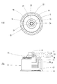
ノズルチップC2は、図2、図4(a)および(b)に示すように、外周が本体C1の注出部17内周に凹凸嵌合によって嵌合保持され、内周が突出部24の縦溝26とで内容液の通路として確保される周壁30と、周壁30の上端を覆う隔壁31とを備えている。
隔壁31の上面は、中央部がすり鉢状になっており、その中心には噴霧孔32が設けられており、隔壁31の下面は、突出部24の上面とともに内容液を撹拌しながら噴霧孔32に案内するスピン通路33が設けられている。
As shown in FIGS. 2, 4 (a) and 4 (b ), the nozzle tip C<b>2 has an outer circumference fitted and held by an uneven fitting on the inner circumference of the
The upper surface of the
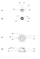
スリット弁C3は、図2、図4(c)および(d)に示すように、本体C1の内側壁16内に入るとともに内周下部に弁押えC4が係合する環状筒35と、環状筒35の内周上端から下方に凹むように湾曲するスリット部36と、環状筒35の外周下部から突設され、上面に内側壁16下端面が当接するとともに下面に弁押えC4が係合するフランジ部37とからなり、スリット部36には、十字状のスリット38が設けられている。
The slit valve C3 is, as shown in FIGS. 2, 4(c) and 4(d), an
弁押えC4は、図2および図5(a)に示すように、外周が本体C1の嵌合内筒19の内周下部に凹凸嵌合によって嵌合保持される嵌合壁40と、嵌合壁40の内周に連設されるリング壁41と、リング壁41の内縁から立設される内周壁42と、外周下端が内周壁42の内周上端に連設され、外周上部がスリット弁C3の環状筒35の内周下部に係合する延長注出筒43とから構成されている。
As shown in FIGS. 2 and 5(a), the valve retainer C4 is fitted with a
嵌合壁40の外周には、上面が嵌合内筒19の下端面に当接し、弁押えC4が本体C1に対して上にズレないようにするフランジ44が突設されている。
弁押えC4は、嵌合壁40の外周上部が本体C1の嵌合内筒19の内周下部に嵌合保持されることで、延長注出筒43の外周がスリット弁C3の環状筒35の下部内周と係合し、また、本体C1の内側壁16の下端面と、嵌合壁40上端面および内周壁42の上端面との間でスリット弁C3のフランジ部37を挟持し、アタッチメントC内にスリット弁C3を保持するようになっている。
On the outer periphery of the
In the valve retainer C4, the outer peripheral upper portion of the
蓋体Dは、図1および図2に示すように、頂壁45と、頂壁45の周縁部から垂設された側周壁46とを備え、頂壁45の下面には、閉蓋時にキャップ本体Bの注出筒6またはアタッチメントCの本体C1の注出部17の外周面上端に軽く当接する位置に内側リング47が垂設され、その外側には、内周下部がキャップ本体Bの側壁5または本体C1の内側壁16の外周上部に当接し、内方を密封する外側リング48が垂設されている。
側周壁46の下部内周には、キャップ本体Bの蓋係合部7またはアタッチメントCの本体C1の蓋係合部18とアンダーカット嵌合して係合し、閉蓋を維持する係合突部49が設けられている。
As shown in FIGS. 1 and 2, the lid body D includes a
An engaging protrusion that engages with the
流通用キャップEは、図2および図5(b)に示すように、アタッチメントCの本体C1の外周壁20の下端面に当接し、外周壁20の内方を封鎖する底板50と、底板50の中央から立設され、外周上部が弁押えC4の延長注出筒43内の下方から挿入された棒状の突部51と、底板50の外縁から立設され、内周が外周壁20の嵌合突条22と嵌合する筒壁52とから構成されている。
突部51の高さは、図2に示すように、流通用キャップEをアタッチメントCに装着した時に突部51の先端部がスリット弁C3のスリット部36の下面中央に当接し、かつ少し下から押し上げるような高さであることが好ましい。
筒壁52の内周には、外周壁20の嵌合突条22と係合し、閉蓋状態を維持させる係合部53が設けられている。
As shown in FIGS. 2 and 5B, the circulation cap E is in contact with the lower end surface of the outer
As shown in FIG. 2, the height of the
An
次に、本実施例の使用態様と作用効果について説明する。
本実施例の吐出容器は、流通時には、図2に示すように、内容液を充填したスクイズ容器Aに、蓋体Dを装着したキャップ本体Bを装着して密封状態で出荷される。
また、アタッチメントCは、流通用キャップEを装着し、吐出容器と別体でアタッチメント部品として吐出容器に添付される。
Next, the mode of use and operational effects of this embodiment will be described.
At the time of distribution, the discharge container of the present embodiment is shipped in a sealed state in which a cap body B having a lid D is attached to a squeeze container A filled with a content liquid as shown in FIG.
The attachment C is attached with a distribution cap E and is attached to the discharge container as an attachment component separately from the discharge container.
流通時のアタッチメントCは、流通用キャップEの突部51の先端部がスリット弁C3のスリット部36の下面中央に当接し、かつ少し下から押し上げ、常にスリット38を押し広げるので、流通時の時間経過などによりスリット38が癒着してスリット自体が機能しなくなることを防止できる。
In the attachment C during distribution, the tip end of the
流通時の吐出容器の場合、閉蓋時には、蓋体Dの側周壁46の係合突部49と、キャップ本体Bの蓋係合部7とが係合し、閉蓋を維持することができる。
また、蓋体Dの内側リング47は、キャップ本体Bの注出筒6の外周面上端に軽く当接し、さらに、外側リング48は、内周下部がキャップ本体Bの側壁5の外周上部に係合し、容器内を密封することができる。
In the case of the discharge container during distribution, when the lid is closed, the engaging
Further, the
内容液を液状で吐出する際には、吐出容器を流通時の状態で使用すればよいので、吐出容器から蓋体Dを外し、図6に示すように、スクイズ容器Aを傾け、内容液を口部1からキャップ本体Bを介して注出筒6から吐出させることができる。
内容液を吐出後は、スクイズ容器Aの傾きを元に戻し、蓋体Dをキャップ本体Bに装着することで閉蓋し、スクイズ容器A内を再び密封することができる。
When the content liquid is discharged in a liquid state, the discharge container may be used in a state in which it is in circulation. Therefore, the lid D is removed from the discharge container, and the squeeze container A is tilted as shown in FIG. It is possible to discharge from the
After discharging the content liquid, the inclination of the squeeze container A is returned to its original position, and the lid D is attached to the cap body B to close the lid, and the inside of the squeeze container A can be sealed again.
内容液を霧状で吐出(噴霧)する際には、まず、流通時の吐出容器から蓋体Dを外した後、アタッチメントCから流通用キャップEを外し、キャップ本体Bの上部からアタッチメントCを装着する。
その際、アタッチメントCは、本体C1の外周壁20の装着係合部21が、キャップ本体Bの蓋係合部7と係合し、キャップ本体Bに固定される。
また、アタッチメントCの弁押えC4は、嵌合壁40の下部内周がキャップ本体Bの側壁5の外周に当接し、さらに、内周壁42の内周および延長注出筒43の下端面がキャップ本体Bの注出筒6外周に当接することで、アタッチメントCの弁押えC4と、キャップ本体Bとの係合を強固にし、弁押えC4がアタッチメントC内で、外れたり、ズレてしまうことを防止できる。
When the content liquid is discharged (sprayed) in the form of a mist, first, the lid D is removed from the discharge container during distribution, then the distribution cap E is removed from the attachment C, and the attachment C is removed from the upper part of the cap body B. Mounting.
At this time, the attachment C is fixed to the cap body B by the mounting
Further, in the valve retainer C4 of the attachment C, the lower inner circumference of the
次に、図7に示すように、アタッチメントCの注出部17を吐出する方向に向けるように吐出容器を傾け、スクイズ容器Aの胴部2をスクイズし、その押圧力でスクイズ容器A内の内容液をノズルチップC2の噴霧孔32から霧状で吐出させることができる。
Next, as shown in FIG. 7, the discharge container is tilted so that the pouring
その際、スクイズ容器A内の押圧された内容液が口部1からキャップ本体Bの注出筒6内周、アタッチメントCの弁押えC4の延長注出筒43の内周、スリット弁C3内方に順に案内され、スリット弁C3のスリット部36を吐出方向に押圧して変形させ、スリット38を開口させる。
次に、押圧された内容液は、スリット38の開口から本体C1の内側壁16内方に案内され、注出部17の注出孔25を通り、ノズルチップC2内に入り、ノズルチップC2内方と突出部24の外周とで撹拌、圧縮されて噴霧孔32から霧状で吐出させることができる。
At that time, the pressed content liquid in the squeeze container A flows from the mouth portion 1 to the inner circumference of the
Next, the pressed content liquid is guided from the opening of the
スクイズ容器Aの胴部2のスクイズを止めると、内容液の圧力が低下し、スリット弁C3のスリット部36の変形が元に戻され、スリット38が閉鎖させるので、吐出が止められる。
また、吐出容器が下向きに向けられていても、スクイズ容器A内の内容液がスリット部36で止められ、噴霧孔32から液が垂れ落ちることを防止できる。
再度、スクイズ容器Aの胴部2をスクイズすると、スリット弁C3のスリット部36が変形してスリット38が開口するので、内容液が無くなるまで吐出を繰り返すことができる。
When the squeeze of the
Further, even if the discharge container is directed downward, the liquid content in the squeeze container A is stopped by the
When the
吐出容器にアタッチメントCを装着した状態で、吐出容器を閉蓋する際には、吐出容器の傾きを元に戻し、図1に示すように、蓋体DをアタッチメントCに装着することで吐出容器内を密封して閉蓋することができる。
その際、蓋体Dの側周壁46の係合突部49と、アタッチメントCの本体C1の蓋係合部18とが係合し、閉蓋を維持できる。
また、蓋体Dの内側リング47は、本体C1の注出部17の外周面上端に軽く当接し、さらに、外側リング48の内周下部が本体C1の内側壁16の外周上部に係合し、吐出容器内を密封できる。
When the discharge container is closed with the attachment C attached, the inclination of the discharge container is returned to its original position, and the lid D is attached to the attachment C as shown in FIG. The inside can be sealed and the lid can be closed.
At that time, the
Further, the
内容液を霧状で吐出するのを止めて液状で吐出するように戻すには、アタッチメントCをキャップ本体Bから再び外すことで内容液を液状で吐出することができる。 In order to stop the discharge of the content liquid in the form of mist and return it to the liquid discharge, the content C can be discharged in the liquid state by removing the attachment C from the cap body B again.
本実施例の吐出容器は、キャップ本体Bに蓋体Dを直接装着することで内容液を液状で吐出する容器として、また、アタッチメントCをキャップ本体Bの上部に装着することで内容液を霧状で吐出する容器として、使用者が簡単に選択して使用することができる。
また、蓋体Dは、キャップ本体BまたはアタッチメントCに装着して閉蓋できるので、蓋体Dをキャップ本体B用とアタッチメントC用とに、複数用意する必要がない。
The discharge container of the present embodiment is a container that discharges the content liquid in a liquid state by directly attaching the lid D to the cap body B, and by attaching the attachment C to the upper portion of the cap body B, the content liquid is atomized. The container can be easily selected and used as a container for discharging in the shape of a circle.
Further, since the lid body D can be attached to the cap body B or the attachment C to close the lid body, it is not necessary to prepare a plurality of lid bodies D for the cap body B and the attachment C.
さらに、スクイズ容器Aの胴部2をスクイズすることでアタッチメントCから内容液を霧状に吐出できるので、噴霧容器としてポンプ機構を使用せず、簡単な構成で噴霧することができ、また、スプリングなどの金属部品を使うことが無く、内容液に錆などが混入することがない。
Further, since the content liquid can be discharged from the attachment C in a mist state by squeezing the
本実施例では、キャップ本体Bの上部に蓋係合部7を配設し、蓋体Dの側周壁46の内周下部に係合突部49を配設し、アンダーカット嵌合することで閉蓋するようにしているが、蓋係合部7および係合突部49を雄ねじおよび雌ねじで形成し、螺合により閉蓋するようにしてもよい。
その際には、アタッチメントCの本体C1の蓋係合部18と、外周壁20の装着係合部21も雄ねじと雌ねじで形成し、螺合により閉蓋するようにすればよい。
以上のように、キャップ本体BおよびアタッチメントCと蓋体Dとの係合形式は、閉蓋状態を維持できれば、どのような形式でもよく、上記実施例の形態に限定されない。
In this embodiment, the
At that time, the
As described above, the type of engagement between the cap body B and the attachment C and the lid D may be any type as long as the closed state can be maintained, and is not limited to the form of the above embodiment.
本実施例では、キャップ本体Bと蓋体Dを別体で成形しているが、キャップ本体Bの外筒9の外周上部の一部と、裏返した蓋体Dの側周壁46の外周上部の一部をヒンジを介して連設して一体成形してもよい。
その際には、蓋体Dをヒンジを介してキャップ本体Bから開蓋した後、アタッチメントCをキャップ本体Bの上部に装着して使用することとなる。
この場合には、アタッチメントCを装着すると、キャップ本体Bは、ヒンジを介して連設された蓋体Dで閉蓋することはできないので、アタッチメントCを閉蓋の都度、取り外し、キャップ本体Bと蓋体Dとで閉蓋する必要がある。
In the present embodiment, the cap body B and the lid body D are molded separately, but a part of the outer peripheral upper portion of the outer cylinder 9 of the cap body B and the outer peripheral upper portion of the side
In that case, after the lid D is opened from the cap body B via the hinge, the attachment C is attached to the upper portion of the cap body B for use.
In this case, when the attachment C is attached, the cap body B cannot be closed with the lid D that is continuously provided via the hinge. Therefore, the attachment C is removed every time the lid is closed, and the cap body B is removed. The lid D needs to be closed.
また、蓋体Dとキャップ本体Bとの間のヒンジを破断して別体とし、アタッチメントCの上部に蓋体Dを装着するようにしてもよい。
さらに、新しい蓋体Dを用意し、アタッチメントCの本体C1にヒンジを介して連設して一体成形するようにしてもよい。
Alternatively, the hinge between the lid body D and the cap body B may be broken to form a separate body, and the lid body D may be attached to the upper portion of the attachment C.
Further, a new lid body D may be prepared and continuously attached to the main body C1 of the attachment C via a hinge so as to be integrally molded.
本発明の吐出容器は、内容液を液状で吐出するキャップ本体にアタッチメントを装着することにより、内容液を霧状で吐出することができ、スクイズ容器に充填された内容液を液状または霧状で吐出する吐出容器として、使用者が簡単に切り替えて使用することができるので、特に調味料、化粧料や薬剤などを充填する吐出容器として好適である。 The discharge container of the present invention can discharge the content liquid in a mist state by attaching the attachment to the cap body that discharges the content liquid in a liquid state, and the content liquid filled in the squeeze container can be in a liquid or mist state. As a discharge container for discharging, the user can easily switch and use the discharge container, and thus it is particularly suitable as a discharge container for filling seasonings, cosmetics, medicines, and the like.
A スクイズ容器
B キャップ本体
C アタッチメント
C1 本体
C2 ノズルチップ
C3 スリット弁
C4 弁押え
D 蓋体
E 流通用キャップ
1 口部
2 胴部
3 嵌合突部
4 上壁
5 側壁
6 注出筒
7、18 蓋係合部
8 内筒
9 外筒
10 装着部
11、49 係合突部
15 基壁
16 内側壁
17 注出部
19 嵌合内筒
20 外周壁
21 装着係合部
22 嵌合突条
23 連結部
24 突出部
25 注出孔
26 縦溝
30 周壁
31 隔壁
32 噴霧孔
33 スピン通路
35 環状筒
36 スリット部
37 フランジ部
38 スリット
40 嵌合壁
41 リング壁
42 内周壁
43 延長注出筒
44 フランジ
45 頂壁
46 側周壁
47 内側リング
48 外側リング
50 底板
51 突部
52 筒壁
53 係合部
A Squeeze container B Cap main body C Attachment C1 Main body C2 Nozzle tip C3 Slit valve C4 Valve retainer D Lid body E Distribution cap 1
31
Claims (6)
キャップ本体は、スクイズ容器の口部に装着される装着部と、内容液を液状で吐出する注出筒とを有し、
アタッチメントは、キャップ本体に着脱可能に装着される本体と、本体の上部に装着され、内容液を霧状で吐出するノズルチップと、本体内に固定されるスリット弁と、本体内に装着され、スリット弁を固定する弁押えとを有することを特徴とする吐出容器。 A discharge container comprising a squeeze container filled with a content liquid, a cap body mounted on the squeeze container, an attachment detachably mounted on the cap body, and a lid body covering the cap body or the attachment,
The cap body has a mounting portion mounted on the mouth portion of the squeeze container, and a pouring cylinder for discharging the content liquid in a liquid state,
The attachment is detachably attached to the cap body, a nozzle tip that is attached to the top of the body and discharges the content liquid in a mist state, a slit valve that is fixed in the body, and an attachment in the body. A discharge container having a valve retainer for fixing a slit valve.
流通用キャップは、アタッチメントの本体の下端面に当接し、内方を封鎖する底板と、底板の中央から立設され、先端部がスリット弁のスリット部に当接する突部と、底板の外縁から立設され、本体と係合して封鎖状態を維持する筒壁とを有することを特徴とする請求項1〜5のいずれかに記載の吐出容器。 The attachment further has a distribution cap that can be attached to the main body during distribution,
The distribution cap is in contact with the lower end surface of the attachment main body, a bottom plate that seals the inside, and a protrusion that is erected from the center of the bottom plate, the tip of which contacts the slit of the slit valve, and the outer edge of the bottom plate. The discharge container according to any one of claims 1 to 5, further comprising: a cylindrical wall that is provided upright and that engages with the main body to maintain a closed state.
Priority Applications (1)
| Application Number | Priority Date | Filing Date | Title |
|---|---|---|---|
| JP2018246056A JP7086834B2 (en) | 2018-12-27 | 2018-12-27 | Discharge container |
Applications Claiming Priority (1)
| Application Number | Priority Date | Filing Date | Title |
|---|---|---|---|
| JP2018246056A JP7086834B2 (en) | 2018-12-27 | 2018-12-27 | Discharge container |
Publications (2)
| Publication Number | Publication Date |
|---|---|
| JP2020104892A true JP2020104892A (en) | 2020-07-09 |
| JP7086834B2 JP7086834B2 (en) | 2022-06-20 |
Family
ID=71448003
Family Applications (1)
| Application Number | Title | Priority Date | Filing Date |
|---|---|---|---|
| JP2018246056A Active JP7086834B2 (en) | 2018-12-27 | 2018-12-27 | Discharge container |
Country Status (1)
| Country | Link |
|---|---|
| JP (1) | JP7086834B2 (en) |
Citations (3)
| Publication number | Priority date | Publication date | Assignee | Title |
|---|---|---|---|---|
| US6176399B1 (en) * | 1999-07-12 | 2001-01-23 | Aptargroup, Inc | Valved dispensing system for multiple dispensing streams |
| JP2010006462A (en) * | 2008-06-30 | 2010-01-14 | Yoshino Kogyosho Co Ltd | Cap |
| JP2016068998A (en) * | 2014-09-29 | 2016-05-09 | 株式会社吉野工業所 | Double container |
-
2018
- 2018-12-27 JP JP2018246056A patent/JP7086834B2/en active Active
Patent Citations (3)
| Publication number | Priority date | Publication date | Assignee | Title |
|---|---|---|---|---|
| US6176399B1 (en) * | 1999-07-12 | 2001-01-23 | Aptargroup, Inc | Valved dispensing system for multiple dispensing streams |
| JP2010006462A (en) * | 2008-06-30 | 2010-01-14 | Yoshino Kogyosho Co Ltd | Cap |
| JP2016068998A (en) * | 2014-09-29 | 2016-05-09 | 株式会社吉野工業所 | Double container |
Also Published As
| Publication number | Publication date |
|---|---|
| JP7086834B2 (en) | 2022-06-20 |
Similar Documents
| Publication | Publication Date | Title |
|---|---|---|
| KR200453458Y1 (en) | Dispenser having dual pump structure | |
| US11655075B2 (en) | Dispensing systems and methods for using the same | |
| JP5457567B2 (en) | Weighing container | |
| JP5215116B2 (en) | Weighing container | |
| JP6478564B2 (en) | Pouring spout | |
| KR200488073Y1 (en) | Container for discharging two kinds of liquids | |
| JPH1072052A (en) | Liquid discharging utensil | |
| JP6639322B2 (en) | Metering container | |
| JP6351470B2 (en) | Squeeze container cap | |
| JP2020104892A (en) | Discharge container | |
| JP5590554B2 (en) | Application container | |
| JPH08230920A (en) | Pouring cap | |
| JP6679167B2 (en) | Fixed volume dispensing container | |
| JP2019119452A (en) | Pouring cap | |
| JP6552205B2 (en) | Foam ejection container | |
| JP3566818B2 (en) | Liquid dispense container | |
| JP2009057084A (en) | Liquid jetting device | |
| JP6465717B2 (en) | Application container | |
| JP4840810B2 (en) | Liquid ejection container | |
| JP3197254U (en) | Pump dispenser | |
| JP7355623B2 (en) | metering pump container | |
| JP6296922B2 (en) | Foam discharge container | |
| JP6202532B2 (en) | Foam discharge container | |
| JP2019206388A (en) | Squeeze container cap | |
| JP3883162B2 (en) | Liquid dispensing container |
Legal Events
| Date | Code | Title | Description |
|---|---|---|---|
| A621 | Written request for application examination |
Free format text: JAPANESE INTERMEDIATE CODE: A621 Effective date: 20210714 |
|
| TRDD | Decision of grant or rejection written | ||
| A977 | Report on retrieval |
Free format text: JAPANESE INTERMEDIATE CODE: A971007 Effective date: 20220526 |
|
| A01 | Written decision to grant a patent or to grant a registration (utility model) |
Free format text: JAPANESE INTERMEDIATE CODE: A01 Effective date: 20220607 |
|
| A61 | First payment of annual fees (during grant procedure) |
Free format text: JAPANESE INTERMEDIATE CODE: A61 Effective date: 20220608 |
|
| R150 | Certificate of patent or registration of utility model |
Ref document number: 7086834 Country of ref document: JP Free format text: JAPANESE INTERMEDIATE CODE: R150 |