JP2020097481A - Straight advance feeder and combination weighing device equipped with the same - Google Patents
Straight advance feeder and combination weighing device equipped with the same Download PDFInfo
- Publication number
- JP2020097481A JP2020097481A JP2018237043A JP2018237043A JP2020097481A JP 2020097481 A JP2020097481 A JP 2020097481A JP 2018237043 A JP2018237043 A JP 2018237043A JP 2018237043 A JP2018237043 A JP 2018237043A JP 2020097481 A JP2020097481 A JP 2020097481A
- Authority
- JP
- Japan
- Prior art keywords
- articles
- feeder
- hopper
- straight
- weighing
- Prior art date
- Legal status (The legal status is an assumption and is not a legal conclusion. Google has not performed a legal analysis and makes no representation as to the accuracy of the status listed.)
- Pending
Links
- 238000005303 weighing Methods 0.000 title claims description 95
- 238000011144 upstream manufacturing Methods 0.000 claims description 17
- 230000007246 mechanism Effects 0.000 claims description 8
- 230000007423 decrease Effects 0.000 abstract 1
- 238000003860 storage Methods 0.000 description 42
- 241000251468 Actinopterygii Species 0.000 description 15
- 239000006185 dispersion Substances 0.000 description 9
- 235000009508 confectionery Nutrition 0.000 description 5
- 230000036544 posture Effects 0.000 description 4
- YBHQCJILTOVLHD-YVMONPNESA-N Mirin Chemical compound S1C(N)=NC(=O)\C1=C\C1=CC=C(O)C=C1 YBHQCJILTOVLHD-YVMONPNESA-N 0.000 description 3
- 244000046052 Phaseolus vulgaris Species 0.000 description 3
- 235000010627 Phaseolus vulgaris Nutrition 0.000 description 3
- 238000004806 packaging method and process Methods 0.000 description 3
- 238000007599 discharging Methods 0.000 description 2
- 238000009826 distribution Methods 0.000 description 2
- 235000013305 food Nutrition 0.000 description 2
- 238000011084 recovery Methods 0.000 description 2
- 235000019685 rice crackers Nutrition 0.000 description 2
- 235000011888 snacks Nutrition 0.000 description 2
- 238000004140 cleaning Methods 0.000 description 1
- 238000001514 detection method Methods 0.000 description 1
- 238000003780 insertion Methods 0.000 description 1
- 230000037431 insertion Effects 0.000 description 1
- 239000000463 material Substances 0.000 description 1
- 239000002184 metal Substances 0.000 description 1
- 238000000034 method Methods 0.000 description 1
- 230000000630 rising effect Effects 0.000 description 1
Images


Classifications
-
- G—PHYSICS
- G01—MEASURING; TESTING
- G01G—WEIGHING
- G01G19/00—Weighing apparatus or methods adapted for special purposes not provided for in the preceding groups
- G01G19/387—Weighing apparatus or methods adapted for special purposes not provided for in the preceding groups for combinatorial weighing, i.e. selecting a combination of articles whose total weight or number is closest to a desired value
- G01G19/393—Weighing apparatus or methods adapted for special purposes not provided for in the preceding groups for combinatorial weighing, i.e. selecting a combination of articles whose total weight or number is closest to a desired value using two or more weighing units
-
- B—PERFORMING OPERATIONS; TRANSPORTING
- B65—CONVEYING; PACKING; STORING; HANDLING THIN OR FILAMENTARY MATERIAL
- B65G—TRANSPORT OR STORAGE DEVICES, e.g. CONVEYORS FOR LOADING OR TIPPING, SHOP CONVEYOR SYSTEMS OR PNEUMATIC TUBE CONVEYORS
- B65G27/00—Jigging conveyors
- B65G27/04—Load carriers other than helical or spiral channels or conduits
-
- B—PERFORMING OPERATIONS; TRANSPORTING
- B65—CONVEYING; PACKING; STORING; HANDLING THIN OR FILAMENTARY MATERIAL
- B65G—TRANSPORT OR STORAGE DEVICES, e.g. CONVEYORS FOR LOADING OR TIPPING, SHOP CONVEYOR SYSTEMS OR PNEUMATIC TUBE CONVEYORS
- B65G27/00—Jigging conveyors
- B65G27/10—Applications of devices for generating or transmitting jigging movements
- B65G27/16—Applications of devices for generating or transmitting jigging movements of vibrators, i.e. devices for producing movements of high frequency and small amplitude
-
- B—PERFORMING OPERATIONS; TRANSPORTING
- B65—CONVEYING; PACKING; STORING; HANDLING THIN OR FILAMENTARY MATERIAL
- B65G—TRANSPORT OR STORAGE DEVICES, e.g. CONVEYORS FOR LOADING OR TIPPING, SHOP CONVEYOR SYSTEMS OR PNEUMATIC TUBE CONVEYORS
- B65G27/00—Jigging conveyors
- B65G27/34—Jigging conveyors comprising a series of co-operating units
-
- G—PHYSICS
- G01—MEASURING; TESTING
- G01G—WEIGHING
- G01G19/00—Weighing apparatus or methods adapted for special purposes not provided for in the preceding groups
- G01G19/387—Weighing apparatus or methods adapted for special purposes not provided for in the preceding groups for combinatorial weighing, i.e. selecting a combination of articles whose total weight or number is closest to a desired value
-
- B—PERFORMING OPERATIONS; TRANSPORTING
- B65—CONVEYING; PACKING; STORING; HANDLING THIN OR FILAMENTARY MATERIAL
- B65G—TRANSPORT OR STORAGE DEVICES, e.g. CONVEYORS FOR LOADING OR TIPPING, SHOP CONVEYOR SYSTEMS OR PNEUMATIC TUBE CONVEYORS
- B65G2203/00—Indexing code relating to control or detection of the articles or the load carriers during conveying
- B65G2203/02—Control or detection
- B65G2203/0208—Control or detection relating to the transported articles
- B65G2203/0258—Weight of the article
-
- B—PERFORMING OPERATIONS; TRANSPORTING
- B65—CONVEYING; PACKING; STORING; HANDLING THIN OR FILAMENTARY MATERIAL
- B65G—TRANSPORT OR STORAGE DEVICES, e.g. CONVEYORS FOR LOADING OR TIPPING, SHOP CONVEYOR SYSTEMS OR PNEUMATIC TUBE CONVEYORS
- B65G3/00—Storing bulk material or loose, i.e. disorderly, articles
- B65G3/04—Storing bulk material or loose, i.e. disorderly, articles in bunkers, hoppers, or like containers
Abstract
Description
本発明は、各種食品や菓子類、等の物品を振動搬送する直進フィーダ、及び、その直進フィーダを備えた組合せ計量装置に関し、更に詳しくは、物品の少量を振動搬送するのに好適な直進フィーダ、及び、多品種の物品を少量ずつ混合計量するのに好適な組合せ計量装置に関する。 The present invention relates to a rectilinear feeder that vibrates and conveys articles such as various foods and confectioneries, and a combination weighing device including the rectilinear feeder, and more specifically, a rectilinear feeder suitable for vibrating and conveying a small amount of articles. And a combination weighing device suitable for mixing and weighing small amounts of various types of articles.
多品種の混合計量に好適な組合せ計量装置としては、例えば、特許文献1に開示されているように、多数連の計量ユニット、および、これに対応する多数台の直進フィーダを横方向に並列配備し、貯留ホッパに貯留した物品を直進フィーダの始端部に流下供給し、各直進フィーダで振動搬送した物品を対応する計量ユニットに供給するように構成したものが知られている。
As a combination weighing device suitable for mixing and weighing a wide variety of products, for example, as disclosed in
例えば、小魚の味醂煮のような物品は、互いにくっついて塊になり易く、少量ずつ計量ユニットに搬送して計量するのが困難であった。例えば、ナッツ、あられ、豆菓子、などに小魚の味醂煮を1,2匹混合したおつまみセットを混合計量するような場合、直進フィーダによって少量の小魚を搬送するのが困難であり、直進フィーダから計量ユニットに小魚を全く供給できなかったり、逆に計量ユニットへの小魚の供給量が過量となったりする場合がある。このため、少量の小魚が供給される計量ホッパを確保するために、小魚用として割当てる直進フィーダ及び計量ユニットの数を増やすなどの対応が必要であった。 For example, articles such as small fish miso-boiled tend to stick to each other to form a lump, and it is difficult to convey the pieces little by little to a weighing unit. For example, when mixing and weighing a snack set that mixes 1 or 2 small fish mirin with nuts, hail, bean confectionery, etc., it is difficult to convey a small amount of small fish with a straight feeder, There is a case where the small fish cannot be supplied to the weighing unit at all, or conversely, the small fish is supplied to the weighing unit excessively. Therefore, in order to secure a weighing hopper to which a small amount of small fish is supplied, it is necessary to take measures such as increasing the number of straight-line feeders and weighing units allocated for small fish.
本発明は、このような点に着目してなされたものであって、互いにくっつきやすい物品を少量ずつ円滑に搬送することができる直進フィーダ、及び、この直進フィーダを用いて混合計量を行うことができる組合せ計量装置を提供することを目的とする。 The present invention has been made paying attention to such a point, and it is possible to perform straight line feeders that can smoothly convey articles that are likely to stick to each other little by little, and to perform mixing and weighing using the straight line feeders. An object of the present invention is to provide a combination weighing device that can be used.
上記目的を達成するために、本発明では次のように構成している。 In order to achieve the above object, the present invention has the following configuration.
(1)本発明に係る直進フィーダは、トラフを振動させて、該トラフ上の物品を搬送する直進フィーダであって、
前記トラフにおける前記物品の搬送通路底面には、前記搬送通路の幅方向の中間に、前記物品の搬送方向に向けて、前記幅方向に次第に大きくなる案内突起が設けられ、前記案内突起の両脇に、通路幅が次第に狭くなる搬送通路が形成されている。
(1) A straight feeder according to the present invention is a straight feeder that vibrates a trough to convey an article on the trough.
A guide projection that gradually increases in the width direction toward the conveyance direction of the article is provided at the bottom of the conveyance path of the article in the trough, in the middle of the conveyance path in the width direction, and both sides of the guide projection are provided. A transport passage is formed in which the width of the passage is gradually narrowed.
本発明によると、互いにくっついて塊になり易い物品は、振動搬送されながら、案内突起によってトラフ幅方向の両側に次第に解され振分けられて、案内突起の両側の通路幅が次第に小幅となる搬送通路を通って少量ずつ振分け搬送されてゆく。これによって、互いにくっつき易い物品であっても、少量ずつ円滑に搬送することができる
(2)本発明の好ましい実施態様では、前記案内突起を、前記物品の前記搬送方向の下流側に設けると共に、前記搬送方向に向けて次第に高く隆起させている。
According to the present invention, an article that sticks to each other and tends to form a lump is gradually unraveled and distributed to both sides in the trough width direction by the guide protrusion while being vibrated and conveyed, and the passage width on both sides of the guide protrusion is gradually reduced. It is sorted and conveyed little by little through the. As a result, even articles that easily stick to each other can be smoothly conveyed little by little. (2) In a preferred embodiment of the present invention, the guide protrusion is provided on the downstream side of the article in the conveyance direction, and The ridge is gradually raised in the conveying direction.
この実施態様によると、振動搬送される塊になり易い物品は、案内突起に乗り上げながら解されてトラフ幅方向の両側の小幅の搬送通路に振分けられ、当該トラフの下流側から少量ずつ搬出される。 According to this embodiment, the articles that are likely to be lumps that are vibrated and conveyed are dislodged while riding on the guide protrusions, distributed to the narrow conveyance passages on both sides in the trough width direction, and discharged little by little from the downstream side of the trough. ..
(3)本発明の他の実施態様では、前記搬送方向の上流側のトラフと下流側のトラフとの2つのトラフを備え、前記2つのトラフが、前記搬送方向に向けて先下がり階段状に縦列配置されており、前記上流側のトラフが、前記案内突起を有すると共に、通路幅が次第に狭くなる前記搬送通路を有する。 (3) In another embodiment of the present invention, two troughs, that is, an upstream side trough and a downstream side trough in the transport direction are provided, and the two troughs form a step-down step toward the transport direction. The upstream troughs are arranged in tandem, and have the guide passages and the conveying passages whose passage widths are gradually narrowed.
この実施態様によると、上段に位置する上流側のトラフにおいて、案内突起によって、トラフ幅方向に少量ずつ振分け搬送されてきた物品が、落差をもって下段に位置する下流側のトラフに移載され、この落差による落下衝撃で、塊となり易い物品を切り離すことができる。 According to this embodiment, in the upstream trough located in the upper stage, the guide projections sort the articles conveyed in small amounts in the width direction of the trough and transfer them to the downstream trough located in the lower stage with a drop. It is possible to separate articles that tend to become lumps due to the drop impact caused by the drop.
(4)本発明の更に他の実施態様では、前記2つのトラフを、それぞれ独立して振動駆動する加振機構を備える。 (4) In still another embodiment of the present invention, a vibrating mechanism that vibrates and drives the two troughs independently of each other is provided.
この実施態様によると、上流側及び下流側の各トラフにおいて搬送状況に応じた振動駆動を行うことができ、くっつき易い物品を好適に解しながら搬送することができる。 According to this embodiment, it is possible to perform vibration drive in each of the upstream and downstream troughs in accordance with the transportation condition, and it is possible to transport an article that easily sticks while being appropriately unraveled.
(5)本発明に係る組合せ計量装置は、上記(1)ないし(4)のいずれかの直進フィーダを複数備える。 (5) A combination weighing device according to the present invention includes a plurality of straight-line feeders according to any of (1) to (4) above.
本発明によると、互いにくっつき易い物品を本発明の直進フィーダによって円滑に搬送して組合せ計量を好適に実施することができる。 According to the present invention, articles that are likely to stick to each other can be smoothly conveyed by the linear feeder of the present invention, and the combination weighing can be suitably performed.
(6)本発明の好ましい実施態様では、複数の直進フィーダが、直線状に並ぶように列設され、各直進フィーダによって搬送される物品が供給される供給ホッパ及び前記供給ホッパから排出される物品を保持してその重量を計量する計量ホッパを、上下に一連に有する計量ユニットの複数連が、直線状に並ぶように列設されている。 (6) In a preferred embodiment of the present invention, a plurality of linear feeders are arranged in a line in a straight line, and a supply hopper to which the articles conveyed by each linear feeder are supplied and an article discharged from the supply hopper. A plurality of series of weighing units having a series of upper and lower weighing hoppers for holding and weighing the weight are arranged in a line in a straight line.
この実施態様によると、供給ホッパ及び計量ホッパを上下に一連に有する計量ユニットの複数連が、直線状に並ぶように列設され、各供給ホッパへ物品を供給する直進フィーダの複数が、直線状に並ぶように列設されるので、例えば、供給ホッパへ供給する物品の品種が多品種に亘る場合のように、計量ユニットの複数連を構成する連の数を多くしたい場合には、直線状に列設される計量ユニット及び直進フィーダを、直線状に増設すればよく、平面的にコンパクトなものとなる。 According to this embodiment, a plurality of series of weighing units having a series of a supply hopper and a weighing hopper are arranged in a line in a straight line, and a plurality of linear feeders for supplying articles to each supply hopper are linear. Since it is arranged in a line, when it is desired to increase the number of stations forming a plurality of stations of the weighing unit, for example, when the articles to be fed to the feeding hopper are of various types, a linear shape can be used. The weighing units and the linear feeders arranged in a line may be added in a straight line, which is compact in plan view.
このように、本発明に係る直進フィーダによれば、互いにくっつき易いような物品を少量ずつ円滑に搬送することができ、また、本発明に係る組合せ計量装置によると、互いにくっつき易いような物品を含む組合せ計量を好適に実施することができる。 As described above, according to the straight-line feeder of the present invention, articles that are likely to stick to each other can be smoothly conveyed little by little, and according to the combination weighing device of the present invention, articles that easily stick to each other can be provided. The combined weighing including can be suitably implemented.
以下、本発明の実施形態について、図面を参照しながら説明する。 Hereinafter, embodiments of the present invention will be described with reference to the drawings.
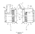
図1は、本発明の一実施形態に係る組合せ計量装置の概略側面図であり、図2は、その概略平面図であり、図3及び図4は、計量装置の概略正面図である。
この実施形態の組合せ計量装置は、各種の食品や菓子、等の多品種(例えば8品種)の物品を所定少量ずつ組合せ計量するものであり、例えば、ナッツ、あられ、豆菓子、などに味醂煮した小魚を1,2匹混合したおつまみセットを混合計量するような場合に好適である。
FIG. 1 is a schematic side view of a combination weighing device according to an embodiment of the present invention, FIG. 2 is a schematic plan view thereof, and FIGS. 3 and 4 are schematic front views of the weighing device.
The combination weighing device of this embodiment is a device for combining and weighing various kinds (for example, 8 kinds) of various foods, confectionery, and the like in predetermined small amounts, and for example, nuts, hail, bean confectionery, etc. It is suitable for a case where a snack set consisting of one or two small fish is mixed and weighed.
この組合せ計量装置は、第1床面F1に設置されて、計量された物品を床面下方に設置した図示されていない包装装置に投入して袋詰めする包装ラインに利用される。 The combination weighing device is installed on the first floor surface F1 and is used in a packaging line for putting the weighed articles into a packaging device (not shown) installed below the floor surface to pack the articles.
なお、構造を理解し易くするために、以下の説明では、図1と図2における横方向、及び、図3、図4における紙面表裏方向を前後方向、また、図1における紙面表裏方向、及び、図3、図4における横方向を左右方向と呼称することとする。 In order to facilitate understanding of the structure, in the following description, the lateral direction in FIGS. 1 and 2, the front-back direction on the paper in FIGS. 3 and 4 and the front-back direction on the paper in FIG. The horizontal direction in FIGS. 3 and 4 is referred to as the left-right direction.
図1に示すように、この組合せ計量装置は、作業者が左右に通過移動可能な中央通路Rを挟んで、前後1組の計量装置1A,1Bが向い合せに配置された構造となっている。各計量装置1A,1Bは、基本的には同仕様に構成されており、以下に、計量装置1A,1Bの詳細な構造を説明する。
As shown in FIG. 1, this combination weighing device has a structure in which a pair of front and
各計量装置1A,1Bにおける内側(中央通路R側)には、第1床面F1に立設した支持台枠2を介して2台の基体3が所定高さ位置において横長に設置されるとともに、基体3の外側(中央通路Rと反対側)には、多数連の計量ユニット4が左右一列状に装備されている。この例では、各計量装置1A,1Bに、それぞれ一列12連の計量ユニット4が装備されて、両計量装置1A,1B合わせて24連の計量ユニット4で多品種の物品の混合組合せ計量を行うようになっている。
Inside of each of the
また、計量ユニット4群の更に外側には、計量される多品種の物品を各計量ユニット4の上部に供給する物品供給部5が配備されている。
Further, an
図5に示すように、計量ユニット4は、基本的に従来と同様であり、物品供給部5から搬送されてきた物品を受け取って一旦貯留して排出する開閉自在なゲートを有する供給ホッパ6と、供給ホッパ6から排出された物品を貯留してその重量を測定して排出する開閉自在なゲートを有する計量ホッパ7と、計量ホッパ7で計量され排出された物品を受け取って一時貯留して排出する開閉自在なゲートを有するメモリホッパ8とを、上下縦列状に配置した構造となっている。
As shown in FIG. 5, the
なお、供給ホッパ6、計量ホッパ7、メモリホッパ8は基体3に対して、脱着可能に支持されるとともに、これらホッパ6,7,8のゲート駆動機構や計量ホッパ6を計量する重量センサ等が基体3に収容装備されている。
The supply hopper 6, the weighing hopper 7, and the memory hopper 8 are detachably supported on the
各基体3は、図2の仮想線で示されるように、横端部の縦向き支点pを中心として旋回回動可能に支持台枠2の上部に支持されており、ホッパ類の脱着やメンテナンスに際しては、基体3を中央通路R側に旋回回動し、計量ユニット4群を大きく露出させてホッパ類の脱着やメンテナンスを容易に行うことができるようになっている。
As shown by the phantom lines in FIG. 2, each
計量ホッパ7の下端には、図5に示すように、それぞれ独立して開閉作動可能な外ゲート7aと内ゲート7bが備えられており、外ゲート7aのみを揺動開放させることで、計量した物品が第1送出径路(a)を介して直接下方の第1集合シュート9に送出され、内ゲート7bのみを揺動開放させることで、計量した物品が第2送出径路(b)を介してメモリホッパ8へ送り込まれて一時貯留されるようになっている。 As shown in FIG. 5, the lower end of the weighing hopper 7 is provided with an outer gate 7a and an inner gate 7b that can be independently opened and closed, and weighs by swinging and opening only the outer gate 7a. The articles are delivered directly to the first collecting chute 9 below through the first delivery path (a), and only the inner gate 7b is swingably opened, so that the weighed articles are delivered through the second delivery path (b). It is sent to the memory hopper 8 and temporarily stored.
各計量ユニット4には、メモリホッパ8が備えられているので、組合せ演算に参加できるホッパ(有効ホッパ)の数を増やすことができる。
Since each weighing
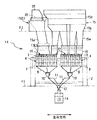
計量ホッパ7とメモリホッパ8の下方には、所定の重量となるように組合せ演算によって選択された複数の計量ホッパ7、あるいは、メモリホッパ8から落下送出された物品を集める4台の第1集合シュート9が左右一列状に配備されるとともに、隣接する2台ずつの第1集合シュート9の下方に、第1集合シュート9で集められた物品を一時的に受け止め貯留する2台の第1集合ホッパ10が配備されている。また、第1集合ゲート10の下方には、各第1集合ゲート10から落下排出された物品を滑落案内して集める第2集合シュート11と、12連の計量ユニット4を用いて計量されて集められた物品を一か所に集めて一時貯留する第2集合ホッパ12が、各計量装置1A,1Bに対してそれぞれ1個ずつ配置されている。
Below the weighing hopper 7 and the memory hopper 8, a plurality of weighing hoppers 7 selected by a combination calculation so as to have a predetermined weight, or a first set of four collecting the articles dropped and delivered from the memory hopper 8. While the chutes 9 are arranged in a line in the left and right, two first sets for temporarily receiving and storing the articles collected by the first collecting chutes 9 below the first collecting chutes 9 for every two adjacent chutes 9. A
更に、図1に示すように、中央通路Rの下方には、各計量装置1A,1Bに1個ずつ備えた第2集合ホッパ12から排出された物品を一箇所に集める最終集合ホッパ13が設置され、この最終集合ホッパ13は、包装装置側からの供給要請指令に基づいて開閉制御される。なお、第2集合ホッパ12から最終集合ホッパ13への物品流下案内径路には金属検知器14が備えられており、金属異物の混入が監視される。
Further, as shown in FIG. 1, below the central passage R, a
物品供給部5には、物品を収容する貯留タンク15と、各貯留タンク15の下端に連設された貯留ホッパ16が備えられるとともに、貯留ホッパ16の下端から繰り出された物品を12連の各計量ユニット4に向けて振動移搬送する12台の直進フィーダ17が、支持台18の上部に左右に並列して配備されている。
The
貯留タンク15は、第1床面F1の更に上方に設置された第2床面F2の開口部に落とし込み支持された下段タンク15aと、その上に脱着可能に位置決め支持された中段タンク15b及び上段タンク15cとで構成され、下段タンク15aの下端に貯留ホッパ16が、後述のように脱着可能に支持されている。
The
直進フィーダ17は、物品の搬送方向の上流側の上流直進フィーダ17aと、下流側の下流直進フィーダ17bを、搬送方向に向けて先下がり階段状に縦列配置して、すなわち、上流直進フィーダ17aが上段に、下流直進フィーダ17bが下段に位置するように縦列配置して構成されている。各直進フィーダ17a、17bは、樋状のトラフ19a,19bと、支持台18の上部に設置した加振機構20a、20bとを備えており、各トラフ19a,19bは、各加振機構20a、20bの振動ヘッド部に脱着可能に連結されている。
The straight-moving
貯留ホッパ16から上流直進フィーダ17aに投入供給された物品は、振動搬送されながら解され、下流直進フィーダ17bに移載され、下流直進フィーダ17bの終端から少量ずつ計量ユニット4の供給ホッパ6に送り込まれる。
直進フィーダ17の上方には、下流直進フィーダ17bの始端及び終端近くにおける物品の積層高さを、例えば、レーザで検知する物品センサ21a,21bがそれぞれ配備されており、その検知情報に基づいて加振機構20a、20bが駆動制御され、直進フィーダ17毎での均一な物品搬送が行われるようになっている。
The articles thrown into and supplied from the
Above the
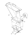
次に、貯留タンク15における下段タンク15aの下端に貯留ホッパ16を脱着可能に連結支持する構造について説明する。図10に示すように、下段タンク15aの下端には、タンク下端の開口より一回り大きいホッパ支持部25が備えられている。このホッパ支持部25の左右に、互いに内向き屈折された左右一対の支持レール26が所定の間隔をもって対向装備されている。
Next, a structure for detachably connecting and supporting the
他方、貯留ホッパ16の上端に形成された矩形の投入口からはフランジ27が延出され、このフランジ27がホッパ支持部25の支持レール26に後方(中央通路Rと反対側)から挿抜可能となっている。また、ホッパ支持部25における内側(中央通路R側)の端部には、挿入されたフランジ27の前端辺を受け止める横長の第1ストッパ28が屈曲立設されるとともに、左右の支持レール26における外側(中央通路Rと反対側)の端部には、挿入されたフランジ27における後端辺の左右端部を受け止める背の低い第2ストッパ29が屈曲立設されている。
On the other hand, a
また、ホッパ支持部25の外方側には、支持した貯留ホッパ16の浮上りを阻止するホッパ規制部30が下向きに屈折形成されている。このホッパ規制部30の下端と第2ストッパ29の上端との間隔が、フランジ27が通過できる寸法に設定されている。
Further, on the outer side of the
従って、図11に示すように、貯留ホッパ16を下段タンク15aに連結する際には、先ず、貯留ホッパ16を、そのフランジ27が若干前下がりとなる傾斜姿勢でホッパ支持部25に接近させ、ホッパ規制部30の下端と外方ストッパ29の上端との間隔を潜り抜けるように支持レール26に挿入してゆく。
Therefore, as shown in FIG. 11, when connecting the
フランジ27の前端辺が第1ストッパ28に当接してそれ以上の挿入が阻止された時点では、フランジ27の後端辺が第2ストッパ29を前方に通過した状態となる。ここで、貯留ホッパ16を水平姿勢に戻してフランジ27の左右端辺を支持レール26に落し込み載置させることで、フランジ27の前後端辺が、第1ストッパ28と第2ストッパ29とで前後移動不能に位置決めされる。これによって貯留ホッパ16が下段タンク15aに対して前後左右に位置決めされた姿勢に吊下げ支持された状態となる。
When the front end side of the
支持レール26に支持された貯留ホッパ16を取り外す際には、貯留ホッパ16の後部を少し持ち上げて、フランジ27の後端辺を第2ストッパ29より上方に移動させ、引き続き貯留ホッパ16を外方に引き出すことで下段タンク16aから抜き外すことができる。
When removing the
このように貯留ホッパ16を、支持レール26に対して、工具を用いることなく簡単に脱着することができ、また、貯留ホッパ16は、フランジ27を備えただけの単純な形態であるので、洗浄等の作業も容易となる。
In this way, the
更に、貯留ホッパ16を、下段タンク15aに吊下げ支持するので、貯留ホッパ16を支持するためのフレーム等を設ける必要がなく、貯留ホッパ16を着脱する際にフレーム等が邪魔になるといったことがない。
Furthermore, since the
上記のように、下段タンク15aは、第2床面F2の開口部に落とし込み支持され、中段タンク15bは下段タンク15aに、上段タンク15cは中段タンク15bに、凹凸部によって位置決めされてそれぞれ載置支持されているので、これらのタンク15a〜15cも工具を用いることなく簡単に脱着して、洗浄等の作業を容易に行うことができる。
As described above, the
なお、図5及び図10に示すように、貯留ホッパ16における上下中間部の側面には透視窓31が備えられており、透視窓31を介して物品の貯留具合を監視することができる。また、貯留ホッパ16の上下中間部にはスライドシャッタ32が備えられており、スライドシャッタ32を調節することでホッパ下端の開口面積を調整し、物品の種類に応じた開口度合で流下送出を行うことができる。また、ホッパ下端を全閉すれば、貯留ホッパ16に物品が残留した状態でも貯留ホッパ16を取り外すことが可能となっている。
As shown in FIGS. 5 and 10, a
上記したタンク構成、及び、フィーダ構成は、例えば、ナッツ、豆菓子、あられ、等の互いにくっつくことのない物品を供給する標準仕様のものであり、例えば、小魚の味醂煮や小さな軽い煎餅などの互いにくっつき易い物品を少量ずつ搬送する一部の直進フィーダ17と、これに対応する貯留タンク15は別の仕様に構成されている。この例では、図2〜図4に示すように、左右方向に並列配備された12台の直進フィーダ17の内、横一端側4台の直進フィーダ17(C)と、これに対応する貯留タンク15(C)が標準仕様とは異なった別仕様となっており、その構成を以下に説明する。
The tank configuration and the feeder configuration described above are standard specifications for supplying articles that do not stick to each other such as nuts, bean confectionery, hail, and the like, and include, for example, small fish mirin and small light rice crackers. A part of the straight-
別仕様の貯留タンク15(C)では、円滑に自重流下しにくい物品の送出のために、幅広のベルトコンベア35が用いられている。このベルトコンベア35は、矩形筒状の上部タンク36の下部に沿って水平に回動するよう配備されている。ベルトコンベア35を回転駆動することで、上部タンク36に貯留した物品を、その底部から強制的に搬送して幅広く落下送出し、下段タンク15aを経て貯留ホッパ16に送り込むようになっている。
In the storage tank 15 (C) of another specification, a
この例においては、一方の計量装置1Aにおける貯留タンク15(C)と、他方の計量装置1Bにおける貯留タンク15(C)の設置姿勢が異なっている。すなわち、一方の計量装置1Aの貯留タンク15(C)では、ベルトコンベア35が、直進フィーダ17の物品の搬送方向と平行する前後方向に回動されるのに対して、他方の計量装置1Bの貯留タンク15(C)では、ベルトコンベア35が、直進フィーダ17の物品の搬送方向と直交する左右方向に回動されるようになっている。
In this example, the storage tank 15(C) of the one weighing device 1A and the storage tank 15(C) of the other weighing
ベルトコンベア35の終端から落下排出された物品は、下段タンク15aを介して貯留ホッパ16に案内されるのであるが、図4に示すように、他方の計量装置1Bの貯留タンク15(C)では、ベルトコンベア35の終端から前後に幅広く送出された物品が、下段タンク15aに搬出される。4台の直進フィーダ17(C)は、左右方向に沿って並んでいるのに対して、ベルトコンベア35からは、物品が、ベルトコンベア35の幅方向である前後方向に幅広く搬出される。
The articles dropped and discharged from the end of the
したがって、仮に、ベルトコンベア35から搬出される物品を、そのまま直下に落下供給すると、左右方向に沿って並んでいる4台の直進フィーダ17(C)の内、中央寄りの2台の直進フィーダ17(C)には、物品が多めに供給される一方、左右の端の各一台の直進フィーダ17(C)に供給される物品は少なめとなる。各直進フィーダ17(C)は、少量の物品を各供給ホッパ6へそれぞれ供給するので、各直進フィーダ17(C)の始端部にベルトコンベア35から供給される物品の量が、上記のように偏ると、供給ホッパ6へ供給される物品が過量となったり、逆に、物品が供給されなかったりすることになる。
Therefore, if an article carried out from the
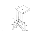
このようにベルトコンベア35から下段タンク15aの左右方向の偏った位置に、物品が供給されるのを防止するために、下段タンク15aの内部には、一対の分散ファネル38を備える物品分散案内部37が収納されている。この物品分散案内部37では、図4に示されるように、一対の分散ファネル38によって、ベルトコンベア35から排出される物品を、4台の直進フィーダ17(C)の配列方向である左右方向へ振分けるように流下案内する。
As described above, in order to prevent the articles from being supplied from the
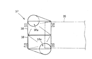
図12は、ベルトコンベア35及び物品分散案内部37を示す概略斜視図であり、図13は、その概略平面図である。
FIG. 12 is a schematic perspective view showing the
2つの分散ファネル38は、ベルトコンベア35の幅方向(前後方向)に沿って、隣接して配置され、両分散ファネル38の矩形の上端入口の境界が、ベルトコンベア35の幅方向の中央に位置するように配置されている。
The two distribution funnels 38 are arranged adjacent to each other along the width direction (front-back direction) of the
各分散ファネル38は、矩形の上端入口に対して、円形の下端出口38aが偏った位置に形成されており、並列配備された2つの分散ファネル38の下端の出口38aが、4台の直進フィーダ17(C)の配列方向である左右方向、すなわち、ベルトコンベア35の搬送方向に離れて位置するよう配置されている。
Each of the dispersion funnels 38 is formed such that a circular
従って、ベルトコンベア35の終端から下段タンク15aの上部に、ベルト幅方向(前後方向)に広く落下排出された物品は、2つの分散ファネル38の流下案内によって直進フィーダ17(C)の配列方向である左右方向に振分けて分散されることになり、4台の直進フィーダ17(C)の始端部に偏り少なく分散して投入される。
Therefore, the articles widely dropped and discharged in the belt width direction (front-rear direction) from the end of the
図7に、標準仕様の直進フィーダ17が、また、図8、図9に、別仕様に構成された直進フィーダ17(C)が示されている。
FIG. 7 shows a straight-
ここでは、例えば、小魚の味醂煮や小さく軽い煎餅などの互いにくっつき易い物品の少量搬送に適した別仕様の直進フィーダ17(C)について、その詳細な構造を説明する。 Here, the detailed structure of the straight-advance feeder 17 (C) of another specification, which is suitable for small-quantity conveyance of articles that easily stick to each other such as small fish mirin and small and light rice crackers, will be described.
図8及び図9に示される別仕様の直進フィーダ17(C)における上流直進フィーダ17aのトラフ19aは、逆台形の断面形状を備えた樋状に形成されている。このトラフ19aは、逆台形を構成する底面及び両側面によって、物品を搬送する搬送通路が構成され、この搬送通路の物品の搬送方向の下流側寄りの幅方向(左右方向)の中間、この例では、中央には、物品を幅方向の両側へ分散案内する案内突起22が突設されている。
The
この案内突起22は、その平面形状が搬送方向に向けて次第に幅広となる前後に細長い三角形状に形成されるとともに、その側面形状が搬送方向に向けてトラフ底面から次第に直線的に隆起する山形に形成されている。案内突起22は、左右中央に位置する前後に長い峰部が滑らかに湾曲した突曲面を有する。
The
この案内突起22によって、その両脇には、搬送方向に向けて次第に幅狭となる搬送通路hが形成される。案内突起22の終端における搬送通路hの横幅は、例えば、小魚が2,3匹程度通過できる幅であるのが好ましい。
Due to the
別仕様の直進フィーダ17(C)における下流直進フィーダ17bのトラフ19bは、物品の搬送方向に向けて段階的に先下がり屈折された底面を備えた逆台形の断面形状の樋状に形成されており、搬送終端側に位置する最下段の搬送通路fは、対象とする物品を1列、例えば、小魚1匹を縦列して搬送するに足る小幅に形成されている。
The
別仕様の直進フィーダ17(C)は以上のように構成されており、上流直進フィーダ17aに供給された物品は加振されながら前方へ搬送され、案内突起22によって左右に振分けられることで、分散された状態で次の下流直進フィーダ17bに送り出される。この場合、くっついて塊になり易い物品が案内突起22に至ると、案内突起22に乗り掛かった物品が加振されることで解され、案内突起22の左右に分散されて、幅狭の搬送通路hを少量の物品が通過搬送される。
The straight-line feeder 17(C) of another specification is configured as described above, and the articles supplied to the upstream straight-
上流直進フィーダ17aから下流直進フィーダ17bに移載される物品は、両フィーダ17a,17b間の段差部において、適度な落下衝撃を受け、これによって物品が切り離されて個々の物品に分離され易くなる。更に、下流直進フィーダ17bで搬送される物品は、2つの段差dを落下移動することで、解し作用を受け、最下流の幅狭の搬送通路fに至る。最下流の搬送通路fでは物品が1列状に整列されながら搬送され、極少量ずつ、例えば、小魚1匹ずつ計量ユニット4の供給ホッパ6に送り込むことが可能となる。
The articles transferred from the upstream
このように本実施形態によれば、上流直進フィーダ17aのトラフ19aの案内突起22によって、例えば、小魚のようにくっついて塊になり易い物品であっても、振動搬送されながら、トラフ幅方向の両側に次第に解されつつ振分けられて、案内突起の両側の通路幅が次第に小幅となる搬送通路を通って少量ずつ振分け搬送され、少量ずつ搬送することができる。
As described above, according to the present embodiment, the
また、上流直進フィーダ17aのトラフ19aから下流直進フィーダ17bのトラフ19bに移載される際の落下衝撃によって、塊になり易い物品を切り離して少量ずつ円滑に搬送することができ、下流直進フィーダ17bのトラフ19bから極少量の物品、例えば、小魚1匹ずつ計量ユニット4の供給ホッパ6に搬出することができる。
Further, the drop impact when transferring from the
図5に示すように、物品供給部5における支持台18には、計量ホッパ6に過剰に供給された物品を排出するためのリジェクト機構50が備えられている。
As shown in FIG. 5, the support table 18 of the
このリジェクト機構50には、前後水平に進退移動可能なリジェクトシュート51と、リジェクトシュート51に導入した物品を回収する回収シュート52と回収容器53とが装備されている。
The
リジェクトシュート51は、計量ホッパ7の前記第1送出径路(a)に正面外側から対向して配備されており、エアーシリンダ54によって進退駆動されるようになっている。通常時には、図5に示すように、リジェクトシュート51は第1送出径路(a)の外側に退避しており、計量ホッパ7における外ゲート7aの開放に伴う物品の第1集合シュート9への排出を妨げることがない。
The
そして、計量ホッパ7で計量された重量値が組合せ演算に不適な過量である場合には、図6に示すように、リジェクトシュート51が第1送出径路(a)に進入するリジェクト状態となる。この状態で、計量ホッパ7の外ゲート7aが開放作動されることで、計量ホッパ7内の物品がリジェクトシュート51に排出され、過量の物品が回収シュート52を介して回収容器53に流下回収される。また、回収が完了するとリジェクトシュート51は第1送出径路(a)から退避した元の位置に移動され、計量ホッパ7の外ゲート7aが閉じられて次の計量に備えられる。
When the weight value weighed by the weighing hopper 7 is unsuitable for the combination calculation, the
なお、リジェクトシュート51の先端には板材からなるガイド部材55が設けられている。このガイド部材55は、リジェクトシュート51が第1送出径路(a)から外方に退避した位置にある時、第1送出径路(a)に外方から対向した位置にあり、計量ホッパ7の外ゲート7aが開放されて排出される物品の外方への飛散をガイド部材55で阻止し、送出された物品を正しく第1集合シュート9に導くようになっている。
A
[その他の実施形態]
本発明は、以下のような形態で実施することもできる。
[Other Embodiments]
The present invention can also be implemented in the following modes.
(1)上記実施形態では、多品種の物品の混合計量に適用して説明したが、本発明の計量装置は、混合計量に限らず、例えば、連数を少なくして単一品種の物品の組合せ計量に適用してもよい。 (1) In the above-described embodiment, the description has been made by applying it to the mixed weighing of various kinds of articles, but the weighing device of the present invention is not limited to the mixed weighing, and for example, the number of stations is reduced to obtain the single type of articles. It may be applied to combination weighing.
(2)別仕様の直進フィーダ17(C)を、縦列配備した3段以上の多段直進フィーダとして構成することもできる。 (2) The straight feeder 17(C) of another specification can be configured as a multistage straight feeder having three or more stages arranged in cascade.
(3)別仕様の直進フィーダ17(C)を、案内突起22を備えた直進フィーダのみで構成することもできる。この場合、直進フィーダの終端側の搬送通路を、物品を1列に整列案内する小幅にしておくとよい。
(3) The straight-advance feeder 17 (C) of another specification can be configured only by the straight-advance feeder having the
(4)案内突起22を、搬送方向全長において同高さで、搬送方向上流の先端が先鋭な平面形状が三角形の縦壁状に構成することもできる。 (4) The guide protrusions 22 may be formed in the shape of a vertical wall having the same height in the entire length in the transport direction and a triangular shape in a plan view having a sharp tip at the upstream side in the transport direction.
(5)案内突起22の位置は、搬送通路の幅方向の中央に限らず、中央からずれた位置に形成してもよい。また、物品の品種によっては、案内突起22を搬送方向の複数個所に設置して、複数回の分散作用を付与する形態で実施することもできる。
(5) The position of the
1A 計量装置
1B 計量装置
4 計量ユニット
5 物品供給部
6 供給ホッパ
7 計量ホッパ
8 メモリホッパ
15 貯留タンク
16 貯留ホッパ
17 直進フィーダ
17a 上流直進フィーダ
17b 下流直進フィーダ
19a トラフ
19b トラフ
22 案内突起
h 搬送通路
f 搬送通路
Claims (6)
前記トラフにおける前記物品の搬送通路底面には、前記搬送通路の幅方向の中間に、前記物品の搬送方向に向けて、前記幅方向に次第に大きくなる案内突起が設けられ、
前記案内突起の両脇に、通路幅が次第に狭くなる搬送通路が形成されている、
ことを特徴とする直進フィーダ。 A straight-line feeder that vibrates a trough to convey articles on the trough,
On the bottom surface of the transfer passage of the article in the trough, a guide protrusion that is gradually increased in the width direction is provided in the middle of the width direction of the transfer passage toward the conveyance direction of the article,
On both sides of the guide protrusion, a conveying passage having a gradually narrowing passage width is formed,
A straight line feeder characterized by that.
請求項1に記載の直進フィーダ。 The guide protrusion is provided on the downstream side in the transport direction of the article, and is gradually raised toward the transport direction.
The straight feeder according to claim 1.
前記2つのトラフが、前記搬送方向に向けて先下がり階段状に縦列配置されており、
前記上流側のトラフが、前記案内突起を有すると共に、通路幅が次第に狭くなる前記搬送通路を有する、
請求項1または2に記載の直進フィーダ。 Two troughs are provided, an upstream trough and a downstream trough in the transport direction,
The two troughs are vertically arranged in a step-down manner toward the transport direction,
The upstream trough has the guide projection and the transport passage having a gradually narrowed passage width.
The straight feeder according to claim 1.
請求項3に記載の組合せ計量装置。 A vibrating mechanism for independently vibrating the two troughs,
The combination weighing device according to claim 3.
ことを特徴とする組合せ計量装置。 A plurality of linear feeders according to any one of claims 1 to 4 are provided,
A combination weighing device characterized by the above.
請求項5に記載の組合せ計量装置。 A plurality of rectilinear feeders are arranged in a line in a straight line, and a supply hopper to which the articles conveyed by each rectilinear feeder are supplied and a weighing hopper that holds the articles discharged from the supply hopper and weighs the weight of the articles. , A plurality of stations of weighing units having a series in the top and bottom are arranged in a line in a straight line,
The combination weighing device according to claim 5.
Priority Applications (5)
| Application Number | Priority Date | Filing Date | Title |
|---|---|---|---|
| JP2018237043A JP2020097481A (en) | 2018-12-19 | 2018-12-19 | Straight advance feeder and combination weighing device equipped with the same |
| US17/286,147 US20210354930A1 (en) | 2018-12-19 | 2019-12-13 | Linear feeder and combination weighing device provided with the same |
| CN201980070791.6A CN112955388A (en) | 2018-12-19 | 2019-12-13 | Straight feeder and combined metering device with same |
| PCT/JP2019/048985 WO2020129851A1 (en) | 2018-12-19 | 2019-12-13 | Straight advance feeder and combination weighing device provided with same |
| EP19897969.2A EP3892572A4 (en) | 2018-12-19 | 2019-12-13 | Straight advance feeder and combination weighing device provided with same |
Applications Claiming Priority (1)
| Application Number | Priority Date | Filing Date | Title |
|---|---|---|---|
| JP2018237043A JP2020097481A (en) | 2018-12-19 | 2018-12-19 | Straight advance feeder and combination weighing device equipped with the same |
Publications (2)
| Publication Number | Publication Date |
|---|---|
| JP2020097481A true JP2020097481A (en) | 2020-06-25 |
| JP2020097481A5 JP2020097481A5 (en) | 2021-11-11 |
Family
ID=71101390
Family Applications (1)
| Application Number | Title | Priority Date | Filing Date |
|---|---|---|---|
| JP2018237043A Pending JP2020097481A (en) | 2018-12-19 | 2018-12-19 | Straight advance feeder and combination weighing device equipped with the same |
Country Status (5)
| Country | Link |
|---|---|
| US (1) | US20210354930A1 (en) |
| EP (1) | EP3892572A4 (en) |
| JP (1) | JP2020097481A (en) |
| CN (1) | CN112955388A (en) |
| WO (1) | WO2020129851A1 (en) |
Families Citing this family (1)
| Publication number | Priority date | Publication date | Assignee | Title |
|---|---|---|---|---|
| JP7114189B2 (en) * | 2018-12-19 | 2022-08-08 | 大和製衡株式会社 | Combination weighing device |
Citations (7)
| Publication number | Priority date | Publication date | Assignee | Title |
|---|---|---|---|---|
| JPS6256206A (en) * | 1985-09-02 | 1987-03-11 | Iseki & Co Ltd | Transfer apparatus for fruit or the like |
| JPH0237118U (en) * | 1988-08-31 | 1990-03-12 | ||
| JPH07215480A (en) * | 1994-01-26 | 1995-08-15 | Kyokuto Kaihatsu Kogyo Co Ltd | Device for arranging container or the like |
| JP3198972U (en) * | 2015-05-20 | 2015-07-30 | 株式会社イシダ | Conveying device and combination weighing device using it |
| JP2018048012A (en) * | 2016-09-23 | 2018-03-29 | Ntn株式会社 | Aligning and conveying device |
| JP2018077074A (en) * | 2016-11-08 | 2018-05-17 | 大和製衡株式会社 | Weighing device |
| WO2018153812A1 (en) * | 2017-02-21 | 2018-08-30 | Cabinplant International A/S | A vibration separator system for conveying and separating meat pieces |
Family Cites Families (7)
| Publication number | Priority date | Publication date | Assignee | Title |
|---|---|---|---|---|
| US3730386A (en) * | 1971-05-10 | 1973-05-01 | Wright Machinery Co | Article arranging and counting machine |
| JP4118710B2 (en) * | 2003-03-05 | 2008-07-16 | 株式会社イシダ | Weighing device |
| JP4852386B2 (en) * | 2006-10-06 | 2012-01-11 | ヤマハ発動機株式会社 | Component supply device and surface mounter |
| JP5633738B2 (en) * | 2010-09-27 | 2014-12-03 | 株式会社ダイフク | Goods transport equipment |
| CN103569645B (en) * | 2012-07-26 | 2016-01-27 | Ykk株式会社 | Arrangement of parts device |
| US9463935B1 (en) * | 2014-03-24 | 2016-10-11 | Vibratory Solutions, Llc | Vibratory product conveyor system |
| EP3401654B1 (en) * | 2016-01-07 | 2020-03-18 | Ishida Co., Ltd. | Combination weighing device |
-
2018
- 2018-12-19 JP JP2018237043A patent/JP2020097481A/en active Pending
-
2019
- 2019-12-13 WO PCT/JP2019/048985 patent/WO2020129851A1/en unknown
- 2019-12-13 CN CN201980070791.6A patent/CN112955388A/en active Pending
- 2019-12-13 EP EP19897969.2A patent/EP3892572A4/en active Pending
- 2019-12-13 US US17/286,147 patent/US20210354930A1/en not_active Abandoned
Patent Citations (7)
| Publication number | Priority date | Publication date | Assignee | Title |
|---|---|---|---|---|
| JPS6256206A (en) * | 1985-09-02 | 1987-03-11 | Iseki & Co Ltd | Transfer apparatus for fruit or the like |
| JPH0237118U (en) * | 1988-08-31 | 1990-03-12 | ||
| JPH07215480A (en) * | 1994-01-26 | 1995-08-15 | Kyokuto Kaihatsu Kogyo Co Ltd | Device for arranging container or the like |
| JP3198972U (en) * | 2015-05-20 | 2015-07-30 | 株式会社イシダ | Conveying device and combination weighing device using it |
| JP2018048012A (en) * | 2016-09-23 | 2018-03-29 | Ntn株式会社 | Aligning and conveying device |
| JP2018077074A (en) * | 2016-11-08 | 2018-05-17 | 大和製衡株式会社 | Weighing device |
| WO2018153812A1 (en) * | 2017-02-21 | 2018-08-30 | Cabinplant International A/S | A vibration separator system for conveying and separating meat pieces |
Also Published As
| Publication number | Publication date |
|---|---|
| EP3892572A1 (en) | 2021-10-13 |
| WO2020129851A1 (en) | 2020-06-25 |
| CN112955388A (en) | 2021-06-11 |
| EP3892572A4 (en) | 2022-01-26 |
| US20210354930A1 (en) | 2021-11-18 |
Similar Documents
| Publication | Publication Date | Title |
|---|---|---|
| JP2020097481A (en) | Straight advance feeder and combination weighing device equipped with the same | |
| WO2020129853A1 (en) | Combination weighing device | |
| WO2020129852A1 (en) | Combination weighing apparatus | |
| JP7009628B2 (en) | Combination weighing device | |
| EP3892970B1 (en) | Combination weighing device | |
| JP6896341B2 (en) | Troughs, supply feeders and weighing devices | |
| JP2006194722A (en) | Combinational metering device | |
| JP7332259B2 (en) | Trough for straight feeder and combination weigher equipped with the same | |
| JP7094645B2 (en) | Article alignment device | |
| JP7455481B2 (en) | Combination weighing device | |
| JP7220952B2 (en) | Combination weighing device | |
| JP2024057797A (en) | Combination Weighing Device | |
| JP2004020259A (en) | Combination metering apparatus | |
| JP2015229559A (en) | Article feeding device and article feeding method | |
| JPH08289644A (en) | Crop feeding chute structure of crop classification apparatus | |
| JPH0798242A (en) | Article gathering device of combination weighing device |
Legal Events
| Date | Code | Title | Description |
|---|---|---|---|
| A521 | Request for written amendment filed |
Free format text: JAPANESE INTERMEDIATE CODE: A523 Effective date: 20210928 |
|
| A621 | Written request for application examination |
Free format text: JAPANESE INTERMEDIATE CODE: A621 Effective date: 20210928 |
|
| A131 | Notification of reasons for refusal |
Free format text: JAPANESE INTERMEDIATE CODE: A131 Effective date: 20221004 |
|
| A521 | Request for written amendment filed |
Free format text: JAPANESE INTERMEDIATE CODE: A523 Effective date: 20221124 |
|
| A131 | Notification of reasons for refusal |
Free format text: JAPANESE INTERMEDIATE CODE: A131 Effective date: 20230207 |
|
| A02 | Decision of refusal |
Free format text: JAPANESE INTERMEDIATE CODE: A02 Effective date: 20230801 |