JP2020090967A - Power transmission device for vehicle - Google Patents
Power transmission device for vehicle Download PDFInfo
- Publication number
- JP2020090967A JP2020090967A JP2018226783A JP2018226783A JP2020090967A JP 2020090967 A JP2020090967 A JP 2020090967A JP 2018226783 A JP2018226783 A JP 2018226783A JP 2018226783 A JP2018226783 A JP 2018226783A JP 2020090967 A JP2020090967 A JP 2020090967A
- Authority
- JP
- Japan
- Prior art keywords
- gear
- shaft
- counter
- vehicle
- transmission device
- Prior art date
- Legal status (The legal status is an assumption and is not a legal conclusion. Google has not performed a legal analysis and makes no representation as to the accuracy of the status listed.)
- Granted
Links
Images


Abstract
Description
本発明は、車両の動力伝達装置に関する。 The present invention relates to a power transmission device for a vehicle.
特許文献1には、走行用動力源のモータが出力した動力を駆動輪に伝達する動力伝達装置について、モータの回転数を減速するギヤ機構を備え、このギヤ機構は複数の歯車対によって構成されていることが開示されている。 Patent Document 1 discloses a power transmission device that transmits the power output from a motor of a traveling power source to a drive wheel, and includes a gear mechanism that reduces the rotation speed of the motor, and the gear mechanism includes a plurality of gear pairs. Is disclosed.
特許文献1に記載された構成では、ギヤ機構を構成する歯車が全て外歯車であるため、各歯車の歯面は全て径方向外側に位置することになる。そのため、掻き上げ潤滑によってギヤ機構の全歯車の歯面にオイルを供給することが可能である。 In the configuration described in Patent Document 1, since all the gears forming the gear mechanism are external gears, the tooth surfaces of each gear are all located radially outside. Therefore, it is possible to supply the oil to the tooth surfaces of all the gears of the gear mechanism by the scraping lubrication.
ところで、上述したギヤ機構を構成する歯車に、内歯車を用いることが考えられる。この場合のギヤ機構は、同軸上に並んで配置される二つの歯車のうちの一方が内歯車により構成される。そして、平行な二軸の間が、内歯車と外歯車とからなる歯車対によって連結される。しかしながら、内歯車と外歯車とが噛み合う歯車対では、内歯車の歯面は径方向内側に位置することになり、従来の掻き上げ潤滑では、内歯車の歯面にオイルを供給することが難しい。 By the way, it is conceivable to use an internal gear as a gear forming the above-mentioned gear mechanism. In the gear mechanism in this case, one of the two gears arranged side by side on the same axis is an internal gear. The parallel two axes are connected by a gear pair including an internal gear and an external gear. However, in the gear pair in which the internal gear and the external gear mesh, the tooth surface of the internal gear is located radially inward, and it is difficult to supply oil to the tooth surface of the internal gear with conventional scraping lubrication. ..
本発明は、上記事情に鑑みてなされたものであって、平行な二軸の間で動力を伝達する歯車対について内歯車を用いた場合、内歯車の歯面にオイルを供給することができる車両の動力伝達装置を提供することを目的とする。 The present invention has been made in view of the above circumstances, and when an internal gear is used for a gear pair that transmits power between two parallel shafts, oil can be supplied to the tooth surface of the internal gear. An object is to provide a power transmission device for a vehicle.
本発明は、回転軸に設けられた外歯車である第1ギヤと、前記回転軸と平行に配置された平行軸に設けられ、前記第1ギヤと噛み合う内歯車である第2ギヤと、前記平行軸上に前記第2ギヤと軸線方向に並んで配置された外歯車である第3ギヤと、駆動輪に連結された駆動軸に設けられ、前記第3ギヤと噛み合う外歯車である第4ギヤと、を有するギヤ機構を備え、前記ギヤ機構は、前記回転軸の回転数を減速し、動力源から出力された動力が前記ギヤ機構および前記駆動軸を介して前記駆動輪に伝達する車両の動力伝達装置であって、前記第4ギヤの一部は、前記ギヤ機構を収容するケースの内部に貯留されたオイルに浸かっており、前記第3ギヤおよび前記第4ギヤは、はすば歯車であり、前記第3ギヤの歯のねじれ方向および前記第4ギヤの歯のねじれ方向は、前記第4ギヤが掻き上げたオイルが前記第2ギヤの歯面に供給されるねじれ方向に設定されていることを特徴とする。 The present invention provides a first gear that is an external gear that is provided on a rotating shaft, a second gear that is an internal gear that is provided on a parallel shaft that is arranged parallel to the rotating shaft, and that meshes with the first gear, and A third gear, which is an external gear arranged on the parallel shaft side by side with the second gear in the axial direction, and a fourth gear, which is provided on the drive shaft connected to the drive wheel and meshes with the third gear. And a gear mechanism having a gear, wherein the gear mechanism decelerates the rotational speed of the rotary shaft, and the power output from a power source is transmitted to the drive wheels via the gear mechanism and the drive shaft. A part of the fourth gear is submerged in oil stored inside a case that houses the gear mechanism, and the third gear and the fourth gear are helical. The gear is a gear, and the twisting direction of the teeth of the third gear and the twisting direction of the teeth of the fourth gear are set to the twisting direction in which the oil scraped up by the fourth gear is supplied to the tooth surface of the second gear. It is characterized by being.
また、前記ギヤ機構は、前記第1ギヤから第4ギヤのうち前記第4ギヤのみが前記オイルに浸かっており、前記第3ギヤと前記第4ギヤとの噛み合い部は、前記平行軸の径方向で、前記第2ギヤの歯面よりも径方向内側に配置され、前記第3ギヤの歯のねじれ方向および前記第4ギヤの歯のねじれ方向は、前記車両が前進する場合の回転方向に前記第4ギヤが回転すると、前記噛み合い部において前記第3ギヤの歯と前記第4ギヤの歯との接触部分が、軸線方向で前記第2ギヤとは反対側から前記第2ギヤが配置されている側に移動するねじれ方向に設定されてもよい。 Further, in the gear mechanism, only the fourth gear among the first gear to the fourth gear is immersed in the oil, and the meshing portion between the third gear and the fourth gear has a diameter of the parallel shaft. In the direction of the radial direction inside the tooth surface of the second gear, the twisting direction of the teeth of the third gear and the twisting direction of the teeth of the fourth gear correspond to the rotation direction when the vehicle moves forward. When the fourth gear rotates, the contact portion between the tooth of the third gear and the tooth of the fourth gear in the meshing portion is arranged with the second gear from the side opposite to the second gear in the axial direction. It may be set in a twisting direction in which the moving side moves.
この構成によれば、第3ギヤの歯と第4ギヤの歯との接触部分が軸線方向で内歯車とは反対側から内歯車が配置されている側に移動するため、第3ギヤと第4ギヤとの噛み合い部から軸線方向で内歯車側に向けてオイルを飛ばすことができる。これにより、第3ギヤと第4ギヤとの噛み合い部から内歯車の歯面にオイルを供給することができる。 According to this configuration, the contact portion between the teeth of the third gear and the teeth of the fourth gear moves in the axial direction from the side opposite to the internal gear to the side on which the internal gear is arranged. Oil can be splashed from the meshing part with the four gears toward the internal gear side in the axial direction. As a result, oil can be supplied to the tooth surface of the internal gear from the meshing portion between the third gear and the fourth gear.
また、前記平行軸上では、前記車両の前進方向に向かって右側に前記第2ギヤが配置され、その左側に前記第3ギヤが配置されており、前記第3ギヤの歯のねじれ方向は、左ねじれであり、前記第4ギヤの歯のねじれ方向は、右ねじれであってもよい。 Further, on the parallel axes, the second gear is arranged on the right side in the forward direction of the vehicle, the third gear is arranged on the left side thereof, and the twisting direction of the teeth of the third gear is It may be left-handed twist, and the twisting direction of the teeth of the fourth gear may be right-handed twist.
この構成によれば、左ねじれの第3ギヤと右ねじれの第4ギヤとが噛み合うため、この噛み合い部から右側に配置された第2ギヤの歯面に向けてオイルを飛ばすことができる。これにより、第4ギヤによって掻き上げたオイルを内歯車である第2ギヤの歯面に供給することができる。 According to this configuration, the left-handed third gear and the right-handed fourth gear mesh with each other, so that oil can be splashed from this meshing portion toward the tooth surface of the second gear arranged on the right side. Thus, the oil scraped up by the fourth gear can be supplied to the tooth surface of the second gear that is the internal gear.
また、前記第2ギヤは、前記平行軸の径方向に延びる連結部によって前記平行軸と一体回転可能に連結されており、前記連結部は、軸線方向に貫通する窓孔を形成し、前記車両が前進する場合の回転方向に前記第4ギヤが回転すると、前記第4ギヤが掻き上げたオイルは前記窓孔を通じて前記第2ギヤの歯面に供給されてもよい。 The second gear is integrally rotatably connected to the parallel shaft by a connecting part extending in the radial direction of the parallel shaft, and the connecting part forms a window hole penetrating in the axial direction. When the fourth gear rotates in the rotation direction when moving forward, the oil scraped up by the fourth gear may be supplied to the tooth surface of the second gear through the window hole.
この構成によれば、第4ギヤが掻き上げたオイルを、窓孔を通じて第2ギヤの歯面に供給することが可能になる。 According to this structure, the oil scraped up by the fourth gear can be supplied to the tooth surface of the second gear through the window hole.
また、前記動力源は、モータであり、前記回転軸は、前記モータのロータ軸であり、前記第1ギヤは、前記ロータ軸の一方の端部に設けられた出力ギヤであり、前記ロータ軸は、前記出力ギヤが片持ち支持される状態で軸受によって前記ケースに対して回転自在に支持されてもよい。 Further, the power source is a motor, the rotating shaft is a rotor shaft of the motor, the first gear is an output gear provided at one end of the rotor shaft, the rotor shaft May be rotatably supported by the bearing with respect to the case in a state where the output gear is cantilevered.
この構成によれば、モータを動力源とする車両に搭載される動力伝達装置について、掻き上げ潤滑によって内歯車の歯面にオイルを供給することができる。これにより、オイルジェット等の部品を追加する必要がなくなる。また、片持ちされるロータ軸の長さを短くでき、出力ギヤのミスアライメントを低減できる。 According to this configuration, in the power transmission device mounted on the vehicle that uses the motor as the power source, it is possible to supply oil to the tooth surface of the internal gear by scraping lubrication. This eliminates the need to add parts such as oil jets. Further, the length of the cantilevered rotor shaft can be shortened, and misalignment of the output gear can be reduced.
また、前記平行軸上では、前記車両の前進方向に向かって左側に前記第2ギヤが配置され、その右側に前記第3ギヤが配置されており、前記第3ギヤの歯のねじれ方向は、右ねじれであり、前記第4ギヤの歯のねじれ方向は、左ねじれであってもよい。 Further, on the parallel shafts, the second gear is arranged on the left side in the forward direction of the vehicle, the third gear is arranged on the right side thereof, and the twisting direction of the teeth of the third gear is The twist may be right, and the twist direction of the teeth of the fourth gear may be left twist.
この構成によれば、右ねじれの第3ギヤと左ねじれの第4ギヤとが噛み合うため、この噛み合い部から左側に配置された第2ギヤの歯面に向けてオイルを飛ばすことができる。これにより、第4ギヤによって掻き上げたオイルを内歯車である第2ギヤの歯面に供給することができる。 According to this configuration, the third gear having a right-hand twist and the fourth gear having a left-hand twist mesh with each other, so that oil can be splashed from this meshing portion toward the tooth surface of the second gear arranged on the left side. Thus, the oil scraped up by the fourth gear can be supplied to the tooth surface of the second gear that is the internal gear.
また、前記第1ギヤは、前記車両の上下方向で前記第2ギヤの回転中心位置よりも上方に配置されてもよい。 Further, the first gear may be arranged above the rotation center position of the second gear in the vertical direction of the vehicle.
この構成によれば、第4ギヤにより掻き上げたオイルが第1ギヤに直接当たることを抑制できるため、第1ギヤによる撹拌損失を低減することができる。 According to this configuration, it is possible to prevent the oil scraped up by the fourth gear from directly hitting the first gear, and thus it is possible to reduce the stirring loss due to the first gear.
また、前記第2ギヤは、カウンタギヤ機構のカウンタドリブンギヤであり、前記平行軸は、前記カウンタギヤ機構のカウンタシャフトであり、前記第3ギヤは、前記カウンタギヤ機構のカウンタドライブギヤであり、前記第4ギヤは、ディファレンシャルギヤ機構のデフリングギヤであり、前記駆動軸は、前記ディファレンシャルギヤ機構から出力された動力を前記駆動輪に伝達してもよい。 Further, the second gear is a counter driven gear of a counter gear mechanism, the parallel shaft is a counter shaft of the counter gear mechanism, and the third gear is a counter drive gear of the counter gear mechanism. The fourth gear may be a differential ring gear of a differential gear mechanism, and the drive shaft may transmit the power output from the differential gear mechanism to the drive wheels.
この構成によれば、車両のトランスアクスルに内歯車を含む歯車対を設けた場合に、デフリングギヤにより掻き上げたオイルを内歯車のカウンタドリブンギヤの歯面に供給することができる。 With this configuration, when the transaxle of the vehicle is provided with the gear pair including the internal gear, the oil scraped up by the differential ring gear can be supplied to the tooth surface of the counter driven gear of the internal gear.
本発明によれば、はすば歯車により構成された外歯車が掻き上げたオイルを利用して、その外歯車と軸線方向に並んで配置された内歯車を対象にし、内歯車の歯面にオイルを供給することができる。 According to the present invention, by utilizing the oil scraped up by the external gear configured by the helical gear, the internal gear that is arranged side by side with the external gear in the axial direction is targeted, and the tooth surface of the internal gear is Can supply oil.
以下、図面を参照して、本発明の実施形態における車両の動力伝達装置について具体的に説明する。なお、本発明は、以下に説明する実施形態に限定されるものではない。 Hereinafter, a power transmission device for a vehicle according to an embodiment of the present invention will be specifically described with reference to the drawings. The present invention is not limited to the embodiments described below.
[第1実施形態]
図1は、第1実施形態における車両の概略構成を示す図である。図1に示すように、車両Veは、走行用動力源としてモータ(MG)1を備えている電動車両である。この車両Veは、動力伝達装置10として、出力ギヤ2と、カウンタギヤ機構3と、ディファレンシャルギヤ機構4と、駆動軸5とを備えている。モータ1が出力した動力は、出力ギヤ2、カウンタギヤ機構3、ディファレンシャルギヤ機構4、駆動軸5を介して駆動輪6に伝達される。
[First Embodiment]
FIG. 1 is a diagram showing a schematic configuration of a vehicle in the first embodiment. As shown in FIG. 1, the vehicle Ve is an electric vehicle including a motor (MG) 1 as a driving power source. The vehicle Ve is provided with an
モータ1は、ロータ軸1aと、図示しないロータおよびステータと、を備えている。ロータ軸1aは、ロータと一体回転する回転軸であり、モータ1の出力軸として機能する。このモータ1はインバータを介してバッテリと電気的に接続されている(いずれも不図示)。モータ1はバッテリの電力を使って動力を発生させて駆動輪6を駆動させる。また、モータ1は駆動輪6から伝達される回転によって発電機として機能することが可能なモータジェネレータである。
The motor 1 includes a
出力ギヤ2は、ロータ軸1aと一体回転する外歯車である。図1に示すように、出力ギヤ2はロータ軸1aの一方の端部に設けられたピニオンギヤである。この出力ギヤ2は、カウンタギヤ機構3のカウンタドリブンギヤ31と噛み合っている。カウンタギヤ機構3は、カウンタドリブンギヤ31と、カウンタシャフト32と、カウンタドライブギヤ33とを備えている。
The
カウンタドリブンギヤ31は、カウンタシャフト32と一体回転する内歯車である。カウンタシャフト32は、ロータ軸1aとは異なる軸線上で、ロータ軸1aと平行に配置された平行軸である。カウンタシャフト32には、内歯車のカウンタドリブンギヤ31と外歯車のカウンタドライブギヤ33とが軸線方向に並んで配置されている。図1に示すように、カウンタシャフト32には、車両Veの前進方向に向かって右側にカウンタドリブンギヤ31、その左側にカウンタドライブギヤ33が配置されている。
The counter driven
カウンタドライブギヤ33は、カウンタシャフト32と一体回転する外歯車であり、はすば歯車により構成されている。例えば、カウンタドライブギヤ33はカウンタシャフト32と一体成形されたピニオンギヤである。このカウンタドライブギヤ33は、ディファレンシャルギヤ機構4のデフリングギヤ41と噛み合っている。
The
デフリングギヤ41は、デフケース42と一体回転する外歯車であり、はすば歯車により構成されている。このデフリングギヤ41は駆動軸5と同一の回転中心軸線O3上に配置される。カウンタドライブギヤ33からディファレンシャルギヤ機構4を介して左右の駆動軸5に動力が伝達される。左側の駆動軸5には左側の駆動輪(不図示)が連結されている。右側の駆動軸5には右側の駆動輪6が連結されている。なお、左右を特に区別しない場合には単に駆動軸5、駆動輪6と記載する。
The
このように、動力伝達装置10は、第1軸のロータ軸1aと、第2軸のカウンタシャフト32と、第3軸の駆動軸5とが互いに平行に配置された三軸構造を有する。なお、この説明では、ロータ軸1aの回転中心軸線O1、カウンタシャフト32の回転中心軸線O2、駆動軸5の回転中心軸線O3を用いる場合がある。さらに、軸線方向の配置について、軸線方向の一方側を左側、軸線方向の他方側を右側と記載する場合がある。この左右は、車両Veの前進方向に向かって左側または右側を意味する。
As described above, the
第1軸のロータ軸1aと第2軸のカウンタシャフト32との間は、外歯車の出力ギヤ2と内歯車のカウンタドリブンギヤ31とが噛み合う第1歯車対11によって動力伝達可能に連結されている。駆動側の出力ギヤ2の歯数は、被動側のカウンタドリブンギヤ31の歯数よりも少ない。つまり、第1歯車対11は減速歯車対である。
The
第2軸のカウンタシャフト32と第3軸の駆動軸5との間は、外歯車のカウンタドライブギヤ33と外歯車のデフリングギヤ41とが噛み合う第2歯車対12によって動力伝達可能に連結されている。駆動側のカウンタドライブギヤ33の歯数は、被動側のデフリングギヤ41の歯数よりも少ない。つまり、第2歯車対12は減速歯車対である。
The
動力伝達装置10は、外歯車である出力ギヤ2を第1ギヤ、内歯車であるカウンタドリブンギヤ31を第2ギヤ、外歯車であるカウンタドライブギヤ33を第3ギヤ、外歯車であるデフリングギヤ41を第4ギヤとするギヤ機構を有する。このギヤ機構は、内歯車を含む減速歯車対の第1歯車対11と、外歯車対からなる減速歯車対の第2歯車対12とを備える。このように、動力伝達装置10は、モータ1の回転数をギヤ機構によって減速し、モータ1の出力を駆動輪6に伝達するように構成されている。また、第1歯車対11と第2歯車対12とは、ケース7の内部に収容されている。ケース7は、動力伝達装置10を収容するトランスアクスルケースである。
In the
第1軸であるロータ軸1aには、出力ギヤ2とモータ1のロータとの間の部分に第1軸受81が取り付けられているとともに、ロータに対して出力ギヤ2とは反対側(軸線方向で他方側)の端部に第2軸受82が取り付けられている。この第1軸受81と第2軸受82によってロータ軸1aはケース7に対して回転自在に支持されている。出力ギヤ2は第1軸受81によって片持ち支持された状態で回転する。
A
第2軸であるカウンタシャフト32は、軸線方向で一方側の端部に第3軸受83が取り付けられているとともに、軸線方向で他方側の端部に第4軸受84が取り付けられている。この第3軸受83と第4軸受84とによってカウンタシャフト32はケース7に対して回転自在に支持されている。カウンタドリブンギヤ31とカウンタドライブギヤ33とは第3軸受83と第4軸受84とによって支持された状態で回転する。
The
第3軸である駆動軸5では、左側の駆動軸5が第5軸受85によってケース7に対して回転自在に支持され、右側の駆動軸5が第6軸受86によってケース7に対して回転自在に支持されている。また、デフリングギヤ41は、デフケース42に取り付けられた軸受によってケース7に対して回転自在に支持されている。デフケース42には、デフリングギヤ41の左側に配置された軸受と、デフリングギヤ41の右側に配置された軸受とが取り付けられている。デフリングギヤ41はデフケース42に取り付けられた軸受によって支持された状態で回転する。このデフリングギヤ41はケース7の内部に貯留されたオイル100を掻き上げることができる。動力伝達装置10は、デフリングギヤ41による掻き上げ潤滑を行うように構成されている。
In the
図2は、掻き上げ潤滑構造を説明するための図である。なお、図2には、図1に示す動力伝達装置10について、軸線方向で他方側(右側)から見た場合が模式的に示されている。また、図2に示す回転方向は車両Veが前進走行する際の回転方向である。
FIG. 2 is a diagram for explaining the scraping lubrication structure. Note that FIG. 2 schematically illustrates the
図2に示すように、ケース7の内部には、ギヤを潤滑するためのオイル100が貯留されている。ギヤ機構のうちデフリングギヤ41の一部のみがオイル100に浸かっている。オイル100の油面100aはデフリングギヤ41の一部が浸かる高さであり、上下方向ではデフリングギヤ41の回転中心位置よりも低い位置に設定されている。また、第1ギヤである出力ギヤ2は、上下方向でカウンタドリブンギヤ31の回転中心位置よりも上方に配置されている。そして、車両Veが前進走行する回転方向にデフリングギヤ41が回転すると、デフリングギヤ41が掻き上げたオイル100がデフリングギヤ41とカウンタドライブギヤ33との噛み合い部から飛び、内歯車であるカウンタドリブンギヤ31の歯面31aに供給される。
As shown in FIG. 2,
また、内歯車のカウンタドリブンギヤ31はカウンタドライブギヤ33よりも大径のギヤである。つまり、回転中心軸線O2を中心とする径方向で、カウンタドライブギヤ33とデフリングギヤ41との噛み合い部は、カウンタドリブンギヤ31の歯面31aの径方向内側に配置されている。そのため、径方向内側を向いている内歯の歯面31aに向けて、第2歯車対12の噛み合い部からオイル100を飛ばすことができる。この歯面31aは軸線方向で第2歯車対12の右側に配置されている。すなわち、第2歯車対12の噛み合い部から飛ばされたオイル100は、第1歯車対11と第2歯車対12との間で軸線方向へ飛ぶことになる。
Further, the counter driven
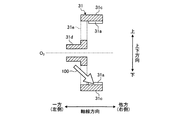
図3は、第2歯車対12の噛み合い部から軸線方向に飛ぶオイル100を説明するための図である。なお、図3には、図2に示すギヤ機構について、上下方向で上側から見た場合が模式的に示されている。また、図3に示す回転方向は車両Veが前進走行する際の回転方向である。
FIG. 3 is a diagram for explaining the
図3に示すように、オイル100は、デフリングギヤ41とカウンタドライブギヤ33との噛み合い部から軸線方向で他方側に位置するカウンタドリブンギヤ31に向けて飛ぶ。デフリングギヤ41は歯すじがねじれているはすば歯車であり、歯41aのねじれ方向が「右ねじれ」に形成されている。カウンタドライブギヤ33は歯すじがねじれているはすば歯車であり、歯33aのねじれ方向が「左ねじれ」に形成されている。ここで、はすば歯車のねじれ方向について、回転中心軸線を垂直方向とし、水平方向の正面からはすば歯車の歯を見た際に、ギヤの歯すじが左上りであれば、ねじれ方向は「左ねじれ」となり、ギヤの歯すじが右上がりであれば、ねじれ方向は「右ねじれ」となる。
As shown in FIG. 3, the
また、軸線方向の位置関係について、第2歯車対12は、内歯車のカウンタドリブンギヤ31に対して軸線方向で一方側(左側)に配置されている。第2歯車対12の噛み合い部では、左ねじれのカウンタドライブギヤ33と右ねじれのデフリングギヤ41とが噛み合っている。そして、右ねじれのデフリングギヤ41が掻き上げたオイル100が、第2歯車対12の噛み合い部から軸線方向で他方側に位置するカウンタドリブンギヤ31に向けて軸線方向に飛ぶ。
Regarding the positional relationship in the axial direction, the
図2に示す位置関係のように、第2歯車対12の噛み合い部がカウンタドライブギヤ33の回転中心位置よりも上下方向で下方に位置する。詳細には、軸線方向で他方側(右側)から見て、時計回りに回転するデフリングギヤ41と、反時計回りに回転するカウンタドライブギヤ33とが、デフリングギヤ41側ではデフリングギヤ41の周方向位置を時計に見立てた位置で2時の部分と、カウンタドライブギヤ33側ではカウンタドライブギヤ33の周方向位置を時計に見立てた位置で7時の部分とで噛み合っている。そして、第2歯車対12の噛み合い部を抜けた先の接線方向に向けてオイル100が飛ぶ。この場合、上下方向および回転中心軸線O2の径方向では、第2歯車対12の噛み合い部から上下方向の下方に向けてオイル100が飛び、回転中心軸線O2の径方向では径方向外側に向けてオイル100が飛ぶ。
As in the positional relationship shown in FIG. 2, the meshing portion of the
さらに、図3に示すねじれ方向を有するはすば歯車により第2歯車対12が構成されている場合、図示した回転方向に第2歯車対12が回転すると、デフリングギヤ41の歯41aとカウンタドライブギヤ33の歯33aとの接触部分は、軸線方向で一方側から他方側に向けて移動する。図3に示す回転状態の第2歯車対12において、はすば歯車同士が噛み合う接触部分では、最初に歯33aと歯41aとが軸線方向の一方側で点接触し、その後に歯33aと歯41aとが線接触する状態となり、この線接触部分が軸線方向で一方側から他方側に移動する。さらに、この線接触部分(接触線)は軸線方向に対して傾斜している。そして、最後には線接触状態から、歯33aと歯41aとが軸線方向で他方側で点接触する状態となり、その後噛み合いが解除される。これにより、デフリングギヤ41により掻き上げられたオイル100は第2歯車対12の噛み合い部から軸線方向で他方側に向けてオイル100が飛ぶことになる。そして、図3に示す軸線方向の位置関係のように、第2歯車対12に対して軸線方向で他方側(右側)に、内歯車のカウンタドリブンギヤ31を配置することによって、カウンタドリブンギヤ31の歯面31aに向けてオイル100を軸線方向に飛ばすことができる。
Further, when the
この第2歯車対12の噛み合い部からカウンタドリブンギヤ31にオイル100を供給するためには、カウンタドリブンギヤ31とカウンタシャフト32とを連結する連結部31bが配置される部分に、軸線方向に貫通する窓孔31e(図4に示す)を設けて、この窓孔31eを通じてオイル100が軸線方向に飛ぶように構成されている。これは、モータ1が出力ギヤ2に対して軸線方向で他方側(右側)に配置されているためである。つまり、出力ギヤ2から軸線方向で他方側に向けてロータ軸1aが延びているため、この出力ギヤ2と噛み合うカウンタドリブンギヤ31は、出力ギヤ2に対して軸線方向で一方側(左側)に設けられた連結部31bによって、カウンタシャフト32と連結される構造となる。
In order to supply the
図4は、カウンタドリブンギヤ31の構造を模式的に示す図である。図5は、図4のA−A線断面図である。
FIG. 4 is a diagram schematically showing the structure of the counter driven
カウンタドリブンギヤ31は、内歯の歯面31aと、径方向に延びる棒状の連結部31bと、内周部に歯面31aが設けられている円筒部31cと、連結部31bの内周側に設けられたボス部31dと、を有する。円筒部31cはボス部31dよりも大径に形成されている。連結部31bは、周方向に等間隔の位置に複数設けられた棒状部位であり、径方向に沿って直線状に延びている。この連結部31bは円筒部31cから径方向内側に延びでボス部31dに連結されている。ボス部31dは、内周部にスプラインが設けられており、カウンタシャフト32の外周部とスプライン嵌合する。
The counter driven
連結部31bが周方向に所定間隔を空けて複数設けられていることによって、大径の円筒部31cと小径のボス部31dとの間には、軸線方向に貫通する窓孔31eが形成される。図4に示す例では、径方向に沿って延びる四つの連結部31bが設けられ、窓孔31eは四つ形成されている。そして、図5に示すように、軸線方向で一方側(左側)から窓孔31eを通じてオイル100が内歯の歯面31aに供給される。
By providing the plurality of connecting
以上説明した通り、第1実施形態によれば、はすば歯車により構成された第2歯車対12の噛み合い部からオイル100を軸線方向に飛ばすことにより、内歯車のカウンタドリブンギヤ31の歯面31aに、デフリングギヤ41が掻き上げたオイル100を供給することができる。これにより、掻き上げ潤滑構造によって内歯車の歯面31aに潤滑用のオイル100を供給することができる。
As described above, according to the first embodiment, the
仮に第2歯車対12が平歯車同士の噛み合い構造である場合、この第2歯車対12の噛み合い部では、駆動側の平歯車の歯と被動側の平歯車の歯とが接触する接触部分は、軸線方向に平行な線接触となる。つまり、平歯車の回転が進んでも歯同士の接触部分が軸線方向に移動することはない。そのため、平歯車同士が噛み合う歯車対では噛み合い部から軸線方向にオイル100を飛ばすことは難しい。これに対して、第2歯車対12がはすば歯車対により構成されており、その歯の接触部分は車両Veが前進走行する回転方向に回転が進むと、内歯車が配置されている軸線方向位置とは反対側から内歯車側の軸線方向位置へと移動することになる。そのため、第1実施形態によれば、第2歯車対12の噛み合い部からオイル100を軸線方向で内歯車側に飛ばすことが可能である。
If the
また、第1軸受81に片持ち支持されている部分のロータ軸1aの軸長を短くすることができ、出力ギヤ2のミスアライメントを低減することができる。さらに、車両Veの上下方向において、出力ギヤ2はカウンタドリブンギヤ31の回転中心よりも上方に配置されていることによって、第2歯車対12の噛み合い部からカウンタドリブンギヤ31の歯面31aに飛ばされたオイルが歯面31aよりも先に出力ギヤ2に当たることを抑制できる。これにより、出力ギヤ2による撹拌損失を低減できる。
In addition, the axial length of the
また、ギヤ機構を構成する四つのギヤのうち、第4ギヤであるデフリングギヤ41のみがケース7に貯留されたオイル100に浸かっているため、仮に内歯車のカウンタドリブンギヤ31がオイル100に浸かっている構成と比較して、撹拌損失を低減できる。
Further, among the four gears constituting the gear mechanism, only the
なお、第1実施形態では、モータ1の出力軸であるロータ軸1aを第1軸とする動力伝達装置10について説明したが、本発明はこれに限定されるものではない。例えば、モータ1は第1軸の回転中心軸線O1とは別軸線上に配置され、第1軸は変速機の出力軸であってもよい。また、第1軸が変速機の出力軸である場合、その変速機の入力軸側に連結された走行用動力源はモータに限らずエンジンであってもよい。つまり、上述した動力伝達装置10は電動車両に限らずエンジン自動車やハイブリッド車両に適用することも可能である。
In the first embodiment, the
また、動力伝達装置10は、ディファレンシャルギヤ機構4が設けられていなくもよい。つまり、はすば歯車の第4ギヤは駆動軸5上に設けられ、駆動軸5と一体回転するように構成されてもよい。この場合、差動装置がないため、モータ1および動力伝達装置10は左側の駆動軸5に設けられたものと、右側の駆動軸に5に設けられたものが左右一対で構成される。
Further, the
また、内歯車を含む第1歯車対11は、平歯車同士が噛み合う構造であってもよく、あるいは、はすば歯車同士が噛み合う構造であってもよい。
The
[第2実施形態]
次に、図6〜図8を参照して、第2実施形態における車両Veの動力伝達装置10について説明する。第2実施形態では、第1実施形態とは異なり、第2歯車対12に対して軸線方向で一方側(左側)に内歯車のカウンタドリブンギヤ31が配置されている。なお、第2実施形態の説明では、第1実施形態と同様の構成については説明を省略し、その参照符号を引用する。
[Second Embodiment]
Next, the
図6は、第2実施形態における車両の概略構成を示す図である。第2実施形態における車両Veの動力伝達装置10は、モータ1が出力した動力を第1歯車対11から第2歯車対12を介して駆動輪6側に向けて伝達する。第1歯車対11は、第2歯車対12に対して軸線方向で一方側(左側)に配置されている。
FIG. 6 is a diagram showing a schematic configuration of the vehicle in the second embodiment. The
軸線方向の位置について、出力ギヤ2と第1軸受81との間に、カウンタドライブギヤ33が配置されている。出力ギヤ2はロータ軸1aの一方側の端部に設けられたピニオンギヤであるため、ロータ軸1aはカウンタドライブギヤ33の軸線方向位置よりも軸線方向で一方側に延びている。この出力ギヤ2は、第1実施形態よりも離れた軸線方向位置に配置された第1軸受81によって片持ち支持された状態で回転することになる。
Regarding the axial position, the
図7は、掻き上げ潤滑構造を説明するための図である。なお、図7には、図6に示す動力伝達装置10について、軸線方向で他方側(右側)から見た場合が模式的に示されている。また、図7に示す回転方向は車両Veが前進走行する際の回転方向である。
FIG. 7 is a diagram for explaining the scraping lubrication structure. Note that FIG. 7 schematically illustrates the
内歯車のカウンタドリブンギヤ31が第2歯車対12に対して軸線方向で一方側に配置された場合も、回転中心軸線O2を中心とする径方向で、カウンタドライブギヤ33とデフリングギヤ41との噛み合い部は、カウンタドリブンギヤ31の歯面31aの径方向内側に配置されている。この歯面31aは軸線方向で第2歯車対12の左側に配置されている。すなわち、第2歯車対12の噛み合い部から飛ばされたオイル100は、軸線方向で一方側(左側)に向けて飛ぶことになる。
Even when the counter driven
図8は、第2歯車対12の噛み合い部から軸線方向に飛ぶオイル100を説明するための図である。なお、図8には、図7に示すギヤ機構について、上下方向で上側から見た場合が模式的に示されている。また、図8に示す回転方向は車両Veが前進走行する際の回転方向である。
FIG. 8 is a diagram for explaining the
図8に示すように、オイル100は、デフリングギヤ41とカウンタドライブギヤ33との噛み合い部から軸線方向で一方側に位置するカウンタドリブンギヤ31に向けて飛ぶ。デフリングギヤ41は、歯41aのねじれ方向が「左ねじれ」に形成されている。カウンタドライブギヤ33は、歯33aのねじれ方向が「右ねじれ」に形成されている。
As shown in FIG. 8, the
また、軸線方向の位置関係について、第2歯車対12は、内歯車のカウンタドリブンギヤ31に対して軸線方向で他方側(右側)に配置されている。第2歯車対12の噛み合い部では、右ねじれのカウンタドライブギヤ33と左ねじれのデフリングギヤ41とが噛み合っている。そして、左ねじれのデフリングギヤ41が掻き上げたオイル100が、第2歯車対12の噛み合い部から軸線方向で一方側に位置するカウンタドリブンギヤ31に向けて軸線方向に飛ぶ。
Regarding the positional relationship in the axial direction, the
さらに、図8に示すねじれ方向を有するはすば歯車により第2歯車対12が構成されている場合、図示した回転方向に第2歯車対12が回転すると、デフリングギヤ41の歯41aとカウンタドライブギヤ33の歯33aとの接触部分は、軸線方向で他方側から一方側に向けて移動する。図8に示す回転状態の第2歯車対12において、はすば歯車同士が噛み合う接触部分では、最初に歯33aと歯41aとが軸線方向の他方側で点接触し、その後に歯33aと歯41aとが線接触する状態となり、この線接触部分が軸線方向で他方側から一方側に移動する。この線接触部分(接触線)は軸線方向に対して傾斜している。そして、最後には線接触状態から、歯33aと歯41aとが軸線方向で一方側で点接触する状態となり、その後噛み合いが解除される。これにより、デフリングギヤ41により掻き上げられたオイル100は、第2歯車対12の噛み合い部から軸線方向で一方側に向けてオイル100が飛ぶことになる。そして、図8に示す軸線方向の位置関係のように、第2歯車対12に対して軸線方向で一方側(左側)に、内歯車のカウンタドリブンギヤ31を配置することによって、カウンタドリブンギヤ31の歯面31aに向けてオイル100を軸線方向に飛ばすことができる。
Further, when the
以上説明した通り、第2実施形態によれば、はすば歯車により構成された第2歯車対12の噛み合い部からオイル100を軸線方向で一方側に飛ばすことにより、内歯車のカウンタドリブンギヤ31の歯面31aに、デフリングギヤ41が掻き上げたオイル100を供給することができる。これにより、内歯車が軸線方向で一方側に配置された構成であっても、掻き上げ潤滑構造によって内歯車の歯面31aに潤滑用のオイル100を供給することができる。
As described above, according to the second embodiment, the
1 モータ
1a ロータ軸
2 出力ギヤ
3 カウンタギヤ機構
4 ディファレンシャルギヤ機構
5 駆動軸
6 駆動輪
7 ケース
10 動力伝達装置
11 第1歯車対
12 第2歯車対
31 カウンタドリブンギヤ
31a 歯面
31b 連結部
31c 円筒部
31d ボス部
31e 窓孔
32 カウンタシャフト
33 カウンタドライブギヤ
33a 歯
41 デフリングギヤ
41a 歯
42 デフケース
81 第1軸受
100 オイル
100a 油面
DESCRIPTION OF SYMBOLS 1
Claims (8)
前記回転軸と平行に配置された平行軸に設けられ、前記第1ギヤと噛み合う内歯車である第2ギヤと、
前記平行軸上に前記第2ギヤと軸線方向に並んで配置された外歯車である第3ギヤと、
駆動輪に連結された駆動軸に設けられ、前記第3ギヤと噛み合う外歯車である第4ギヤと、を有するギヤ機構を備え、
前記ギヤ機構は、前記回転軸の回転数を減速し、
動力源から出力された動力が前記ギヤ機構および前記駆動軸を介して前記駆動輪に伝達する車両の動力伝達装置であって、
前記第4ギヤの一部は、前記ギヤ機構を収容するケースの内部に貯留されたオイルに浸かっており、
前記第3ギヤおよび前記第4ギヤは、はすば歯車であり、
前記第3ギヤの歯のねじれ方向および前記第4ギヤの歯のねじれ方向は、前記第4ギヤが掻き上げたオイルが前記第2ギヤの歯面に供給されるねじれ方向に設定されている
ことを特徴とする車両の動力伝達装置。 A first gear, which is an external gear provided on the rotating shaft,
A second gear that is an internal gear that is provided on a parallel shaft that is arranged parallel to the rotation shaft and that meshes with the first gear;
A third gear, which is an external gear, arranged on the parallel shaft side by side with the second gear in the axial direction;
A gear mechanism provided on a drive shaft connected to the drive wheel and having a fourth gear that is an external gear meshing with the third gear,
The gear mechanism reduces the rotation speed of the rotating shaft,
A power transmission device for a vehicle, wherein power output from a power source is transmitted to the drive wheels via the gear mechanism and the drive shaft,
A part of the fourth gear is immersed in the oil stored inside the case that houses the gear mechanism,
The third gear and the fourth gear are helical gears,
The twisting direction of the teeth of the third gear and the twisting direction of the teeth of the fourth gear are set to a twisting direction in which the oil scraped up by the fourth gear is supplied to the tooth surface of the second gear. A power transmission device for a vehicle.
前記第3ギヤと前記第4ギヤとの噛み合い部は、前記平行軸の径方向で、前記第2ギヤの歯面よりも径方向内側に配置され、
前記第3ギヤの歯のねじれ方向および前記第4ギヤの歯のねじれ方向は、前記車両が前進する場合の回転方向に前記第4ギヤが回転すると、前記噛み合い部において前記第3ギヤの歯と前記第4ギヤの歯との接触部分が、軸線方向で前記第2ギヤとは反対側から前記第2ギヤが配置されている側に移動するねじれ方向に設定されている
ことを特徴とする請求項1に記載の車両の動力伝達装置。 In the gear mechanism, only the fourth gear among the first to fourth gears is immersed in the oil,
The meshing portion of the third gear and the fourth gear is arranged radially inward of the tooth surface of the second gear in the radial direction of the parallel shaft,
The twisting direction of the teeth of the third gear and the twisting direction of the teeth of the fourth gear are the same as the teeth of the third gear at the meshing portion when the fourth gear rotates in the rotation direction when the vehicle moves forward. The contact portion of the fourth gear with the tooth is set in a twisting direction that moves from the side opposite to the second gear to the side where the second gear is arranged in the axial direction. Item 2. A vehicle power transmission device according to item 1.
前記第3ギヤの歯のねじれ方向は、左ねじれであり、
前記第4ギヤの歯のねじれ方向は、右ねじれである
ことを特徴とする請求項1または2に記載の車両の動力伝達装置。 On the parallel axes, the second gear is arranged on the right side in the forward direction of the vehicle, and the third gear is arranged on the left side thereof,
The twist direction of the teeth of the third gear is left twist,
The power transmission device for a vehicle according to claim 1 or 2, wherein a twist direction of a tooth of the fourth gear is a right twist.
前記連結部は、軸線方向に貫通する窓孔を形成し、
前記車両が前進する場合の回転方向に前記第4ギヤが回転すると、前記第4ギヤが掻き上げたオイルは前記窓孔を通じて前記第2ギヤの歯面に供給される
ことを特徴とする請求項3に記載の車両の動力伝達装置。 The second gear is integrally rotatably connected to the parallel shaft by a connecting portion extending in the radial direction of the parallel shaft,
The connecting portion forms a window hole penetrating in the axial direction,
The oil scraped up by the fourth gear is supplied to the tooth surface of the second gear through the window when the fourth gear rotates in the rotation direction when the vehicle moves forward. 3. The vehicle power transmission device according to item 3.
前記回転軸は、前記モータのロータ軸であり、
前記第1ギヤは、前記ロータ軸の一方の端部に設けられた出力ギヤであり、
前記ロータ軸は、前記出力ギヤが片持ち支持される状態で軸受によって前記ケースに対して回転自在に支持されている
ことを特徴とする請求項3または4に記載の車両の動力伝達装置。 The power source is a motor,
The rotating shaft is a rotor shaft of the motor,
The first gear is an output gear provided at one end of the rotor shaft,
The power transmission device for a vehicle according to claim 3, wherein the rotor shaft is rotatably supported by the bearing with the output gear being cantilevered with respect to the case.
前記第3ギヤの歯のねじれ方向は、右ねじれであり、
前記第4ギヤの歯のねじれ方向は、左ねじれである
ことを特徴とする請求項1または2に記載の車両の動力伝達装置。 On the parallel axes, the second gear is arranged on the left side in the forward direction of the vehicle, and the third gear is arranged on the right side thereof,
The twist direction of the teeth of the third gear is right twist,
The power transmission device for a vehicle according to claim 1 or 2, wherein a twist direction of the teeth of the fourth gear is a left twist.
ことを特徴とする請求項1から6のうちのいずれか一項に記載の車両の動力伝達装置。 The vehicle according to any one of claims 1 to 6, wherein the first gear is arranged above a rotation center position of the second gear in a vertical direction of the vehicle. Power transmission device.
前記平行軸は、前記カウンタギヤ機構のカウンタシャフトであり、
前記第3ギヤは、前記カウンタギヤ機構のカウンタドライブギヤであり、
前記第4ギヤは、ディファレンシャルギヤ機構のデフリングギヤであり、
前記駆動軸は、前記ディファレンシャルギヤ機構から出力された動力を前記駆動輪に伝達する
ことを特徴とする請求項1から7のうちのいずれか一項に記載の車両の動力伝達装置。 The second gear is a counter driven gear of a counter gear mechanism,
The parallel axis is a counter shaft of the counter gear mechanism,
The third gear is a counter drive gear of the counter gear mechanism,
The fourth gear is a differential ring gear of a differential gear mechanism,
The power transmission device for a vehicle according to any one of claims 1 to 7, wherein the drive shaft transmits the power output from the differential gear mechanism to the drive wheels.
Priority Applications (1)
| Application Number | Priority Date | Filing Date | Title |
|---|---|---|---|
| JP2018226783A JP7035987B2 (en) | 2018-12-03 | 2018-12-03 | Vehicle power transmission device |
Applications Claiming Priority (1)
| Application Number | Priority Date | Filing Date | Title |
|---|---|---|---|
| JP2018226783A JP7035987B2 (en) | 2018-12-03 | 2018-12-03 | Vehicle power transmission device |
Publications (2)
| Publication Number | Publication Date |
|---|---|
| JP2020090967A true JP2020090967A (en) | 2020-06-11 |
| JP7035987B2 JP7035987B2 (en) | 2022-03-15 |
Family
ID=71012589
Family Applications (1)
| Application Number | Title | Priority Date | Filing Date |
|---|---|---|---|
| JP2018226783A Active JP7035987B2 (en) | 2018-12-03 | 2018-12-03 | Vehicle power transmission device |
Country Status (1)
| Country | Link |
|---|---|
| JP (1) | JP7035987B2 (en) |
Citations (2)
| Publication number | Priority date | Publication date | Assignee | Title |
|---|---|---|---|---|
| JPH0754973A (en) * | 1993-08-09 | 1995-02-28 | Hitachi Constr Mach Co Ltd | Power transmitting device |
| JP2014111983A (en) * | 2012-11-02 | 2014-06-19 | Ricoh Co Ltd | Gear transmission device and image formation apparatus using the same |
-
2018
- 2018-12-03 JP JP2018226783A patent/JP7035987B2/en active Active
Patent Citations (2)
| Publication number | Priority date | Publication date | Assignee | Title |
|---|---|---|---|---|
| JPH0754973A (en) * | 1993-08-09 | 1995-02-28 | Hitachi Constr Mach Co Ltd | Power transmitting device |
| JP2014111983A (en) * | 2012-11-02 | 2014-06-19 | Ricoh Co Ltd | Gear transmission device and image formation apparatus using the same |
Also Published As
| Publication number | Publication date |
|---|---|
| JP7035987B2 (en) | 2022-03-15 |
Similar Documents
| Publication | Publication Date | Title |
|---|---|---|
| EP3138712A1 (en) | Vehicle drive apparatus | |
| CN107438726B (en) | Transmission component and electric drive portion with such transmission component | |
| US10760674B2 (en) | Power transmission apparatus | |
| JP6168236B2 (en) | Final drive device | |
| JP2018048679A (en) | Gear device | |
| JP3701014B2 (en) | Vehicle drive device | |
| JPH11351360A (en) | Lubricating structure in differential device | |
| US11655888B2 (en) | Differential device | |
| JP2007078177A (en) | Power transmission device | |
| JP2020090967A (en) | Power transmission device for vehicle | |
| JP6265096B2 (en) | Vehicle drive device | |
| JP2012137113A (en) | Shaft device | |
| JP2019100409A (en) | Power transmission mechanism | |
| JP2015121255A (en) | Planetary gear mechanism | |
| US10760676B2 (en) | Differential apparatus | |
| JP5708464B2 (en) | Connected structure | |
| JP2008025846A (en) | Revolving part structure of robot or the like | |
| JP2008025846A5 (en) | ||
| WO2019159481A1 (en) | Speed reducing mechanism | |
| JP2009173282A (en) | Power transmission | |
| CN113710527A (en) | Transmission device for hybrid vehicle | |
| JPWO2020161979A1 (en) | Power transmission device | |
| JP6485381B2 (en) | Power transmission device | |
| CN211202762U (en) | Coaxial cylindrical gear transmission device | |
| JP2005047006A (en) | Turning part structure of robot or the like |
Legal Events
| Date | Code | Title | Description |
|---|---|---|---|
| A621 | Written request for application examination |
Free format text: JAPANESE INTERMEDIATE CODE: A621 Effective date: 20210322 |
|
| A977 | Report on retrieval |
Free format text: JAPANESE INTERMEDIATE CODE: A971007 Effective date: 20220125 |
|
| TRDD | Decision of grant or rejection written | ||
| A01 | Written decision to grant a patent or to grant a registration (utility model) |
Free format text: JAPANESE INTERMEDIATE CODE: A01 Effective date: 20220201 |
|
| A61 | First payment of annual fees (during grant procedure) |
Free format text: JAPANESE INTERMEDIATE CODE: A61 Effective date: 20220214 |
|
| R151 | Written notification of patent or utility model registration |
Ref document number: 7035987 Country of ref document: JP Free format text: JAPANESE INTERMEDIATE CODE: R151 |