JP2020076580A - Axial deviation estimation device - Google Patents
Axial deviation estimation device Download PDFInfo
- Publication number
- JP2020076580A JP2020076580A JP2018208319A JP2018208319A JP2020076580A JP 2020076580 A JP2020076580 A JP 2020076580A JP 2018208319 A JP2018208319 A JP 2018208319A JP 2018208319 A JP2018208319 A JP 2018208319A JP 2020076580 A JP2020076580 A JP 2020076580A
- Authority
- JP
- Japan
- Prior art keywords
- sensor
- axis deviation
- vehicle
- lane
- information
- Prior art date
- Legal status (The legal status is an assumption and is not a legal conclusion. Google has not performed a legal analysis and makes no representation as to the accuracy of the status listed.)
- Pending
Links
Images


Abstract
Description
本発明は、車両に搭載されるセンサの軸ずれ量を推定する軸ずれ推定装置に関する。 The present invention relates to an axis deviation estimating device for estimating an axis deviation amount of a sensor mounted on a vehicle.
特許文献1は、複数のセンサ情報を組み合わせて障害物の認識を行う障害物認識装置を開示している。より詳細には、障害物認識装置は、カメラ、レーダ、及び補正手段を備えている。カメラは、障害物を撮像し、撮像結果を示す第1パラメータ情報を取得する。レーダは、障害物を計測し、計測結果を示す第2パラメータ情報を取得する。補正手段は、第1パラメータ情報と第2パラメータ情報に基づいて、カメラ又はレーダの方位角の軸ずれ量を算出する。そして、補正手段は、算出された軸ずれ量に基づいて、カメラ又はレーダの軸ずれを補正する。
特許文献1によれば、カメラ及びレーダのそれぞれによって障害物が認識される。しかしながら、障害物の認識精度が低いと、軸ずれ量の推定精度も低くなる。推定される軸ずれ量が安定しない場合、信頼度の高い軸ずれ量を決定するまでの時間が長くなる。
According to
本発明の1つの目的は、車両に搭載されるセンサの軸ずれ量の推定精度を向上させることができる技術を提供することにある。 An object of the present invention is to provide a technique capable of improving the estimation accuracy of the amount of axial deviation of a sensor mounted on a vehicle.
本発明の1つの観点は、軸ずれ推定装置に関する。
軸ずれ推定装置は、車両に搭載される第1センサと第2センサとの間の軸ずれ量を推定する。
第1センサと第2センサは、車両の周囲の状況を認識し、且つ、それぞれの視野は少なくとも部分的に重なっている。
軸ずれ推定装置は、
第1センサによる認識結果を示す第1認識情報と、第2センサによる認識結果を示す第2認識情報と、車両の周囲の車線の配置を示す車線情報と、が格納される記憶装置と、
第1センサと第2センサとの間の軸ずれ量を推定するプロセッサと
を備える。
プロセッサは、
車線情報に基づいて、車線内の領域と車線の方向から導き出される領域のうち少なくとも一方を、マスク領域として設定し、
第1認識情報及び第2認識情報に基づいて、マスク領域以外の領域に存在する物体を抽出し、
第1センサによる物体の認識結果と第2センサによる物体の認識結果とを対比することによって、軸ずれ量を推定する。
One aspect of the present invention relates to an axis deviation estimating device.
The axis deviation estimation device estimates the axis deviation amount between the first sensor and the second sensor mounted on the vehicle.
The first sensor and the second sensor recognize a situation around the vehicle, and their respective visual fields at least partially overlap.
The axis deviation estimation device is
A storage device that stores first recognition information indicating a recognition result by the first sensor, second recognition information indicating a recognition result by the second sensor, and lane information indicating an arrangement of lanes around the vehicle,
A processor that estimates the amount of axis deviation between the first sensor and the second sensor.
The processor is
Based on the lane information, set at least one of the area within the lane and the area derived from the direction of the lane as the mask area,
An object existing in a region other than the mask region is extracted based on the first recognition information and the second recognition information,
The amount of axis deviation is estimated by comparing the recognition result of the object by the first sensor and the recognition result of the object by the second sensor.
本発明によれば、第1センサによる物体の認識結果と第2センサによる物体の認識結果とを対比することによって、軸ずれ量が推定される。但し、全ての物体が無条件に用いられるわけではない。軸ずれ量の推定精度の低下を招く物体が存在する可能性が高い領域が、マスク領域として設定される。そして、マスク領域以外の領域に存在する物体が軸ずれ量の推定に用いられる。その結果、軸ずれ量の推定精度が向上する。推定される軸ずれ量が安定するため、信頼度の高い軸ずれ量を早期に決定することが可能となる。 According to the present invention, the axis deviation amount is estimated by comparing the object recognition result by the first sensor and the object recognition result by the second sensor. However, not all objects are used unconditionally. A region in which there is a high possibility that there is an object that causes a decrease in the accuracy of estimating the amount of axis deviation is set as the mask region. Then, the object existing in the area other than the mask area is used for estimating the amount of misalignment. As a result, the accuracy of estimating the amount of misalignment is improved. Since the estimated axis deviation amount is stable, it is possible to quickly determine the axis deviation amount with high reliability.
添付図面を参照して、本発明の実施の形態を説明する。 Embodiments of the present invention will be described with reference to the accompanying drawings.
1.車両に搭載されるセンサ
図1は、本実施の形態に係る車両1に搭載されるセンサを説明するための概念図である。車両1は、自動運転を行う機能を有している。自動運転を行うためには、車両1の周囲の状況を認識する必要がある。そのために、車両1は、車両1の周囲の状況を認識(検出)するためのセンサを備えている。より詳細には、センサは、第1センサ10と第2センサ20を含んでいる。
1. Sensor Mounted on Vehicle FIG. 1 is a conceptual diagram for explaining a sensor mounted on the
第1センサ10は、カメラ、ライダー(LIDAR: Laser Imaging Detection and Ranging)、及びレーダのうちのいずれかである。カメラは、車両1の周囲を撮像する。カメラは、例えばステレオカメラである。ライダー及びレーダは、電磁波(レーザ光、電波)を照射し、その反射波に基づいて物体を検出するアクティブセンサである。例えば、ライダーは、複数の方向に向けてレーザ光を順次出力(走査)し、反射光の受光状態に基づいて反射点の距離及び方向を算出することができる。
The
第2センサ20も、カメラ、ライダー、及びレーダのうちいずれかである。但し、第1センサ10と第2センサ20は、一体ではなく、別々に設置されている。
The
第1センサ10と第2センサ20のそれぞれの視野は、少なくとも部分的に重なっている。従って、第1センサ10と第2センサ20によって同一の物体が認識される場合もある。第1センサ10と第2センサ20によって認識される2つの物体が所定の条件を満たす場合、それら2つの物体は同一物体として統合される。このような処理は、「フュージョン処理」と呼ばれる。フュージョン処理は、自動運転制御において利用される。
The respective fields of view of the
ここで、座標系について定義する。「第1座標系」は、第1センサ10に固定されたセンサ座標系である。第1座標系は、互いに直交するX1軸、Y1軸、及びZ1軸で表される。例えば、X1軸は、車両1の前後方向と平行である。典型的には、X1軸は、カメラの場合はその光軸、ライダーやレーダの場合は走査範囲の中心軸と一致する。Y1軸は、車両1の横方向と平行である。Z1軸は、鉛直方向と平行である。
Here, the coordinate system will be defined. The “first coordinate system” is a sensor coordinate system fixed to the
「第2座標系」は、第2センサ20に固定されたセンサ座標系である。第2座標系は、互いに直交するX2軸、Y2軸、及びZ2軸で表される。例えば、X2軸は、車両1の前後方向と平行である。典型的には、X2軸は、カメラの場合はその光軸、ライダーやレーダの場合は走査範囲の中心軸と一致する。Y2軸は、車両1の横方向と平行である。Z2軸は、鉛直方向と平行である。
The “second coordinate system” is a sensor coordinate system fixed to the
第1センサ10の姿勢が変化すると、第1座標系の方向が変化する。第2センサ20の姿勢が変化すると、第2座標系の方向が変化する。このような変化は、以下「軸ずれ」と呼ばれる。軸ずれは、経年変化、センサと物体との接触、等によって発生し得る。軸ずれ量は、軸ずれの大きさである。本実施の形態では、軸ずれ量は、第1座標系と第2座標系との間の方向のずれの大きさで表される。物体認識処理やフュージョン処理を精度良く実施するためには、軸ずれ量を把握しておく必要がある。
When the attitude of the
本実施の形態は、第1センサ10(第1座標系)と第2センサ20(第2座標系)との間の軸ずれ量を精度良く推定するための手法を提案する。軸ずれ量を推定する処理は、以下「軸ずれ推定処理」と呼ばれる。以下、軸ずれ推定処理について詳しく説明する。 The present embodiment proposes a method for accurately estimating the amount of axis deviation between the first sensor 10 (first coordinate system) and the second sensor 20 (second coordinate system). The process of estimating the amount of axis deviation will be referred to as "axis deviation estimation process" below. Hereinafter, the axis deviation estimation processing will be described in detail.
2.軸ずれ推定処理
2−1.比較例
まず、比較例について説明する。図2は、比較例に係る軸ずれ推定処理の概要を説明するための概念図である。車両1は、車線LA内に存在している。車線LAは、車両が走行する走路である。車線境界LBは、車線LAと路肩との間の境界である。車線LAは、左側と右側の車線境界LBに挟まれた領域である。
2. Axis deviation estimation process 2-1. Comparative Example First, a comparative example will be described. FIG. 2 is a conceptual diagram for explaining the outline of the axis deviation estimation process according to the comparative example. The
軸ずれ推定処理には、第1センサ10と第2センサ20のそれぞれによる物体認識(物体検出)の結果が利用される。図2には、認識される物体として、他車両2と道路構造物3が例示されている。他車両2は、車線LA内を走行している。道路構造物3としては、ガードレールや壁が例示される。典型的には、道路構造物3は、車線LAの外側の領域において車線LA(車線境界LB)に沿って配置されている。図3に示される例では、車両1の左側と右側に道路構造物3L、3Rがそれぞれ存在している。
The results of object recognition (object detection) by the
図3は、第1センサ10と第2センサ20のそれぞれによる物体認識の結果の例を概念的に示している。第1点群PC1は、第1センサ10によって検出される物体の表面上の点群である。第1点群PC1の位置は、第1座標系において定義される。第2点群PC2は、第2センサ20によって検出される物体の表面上の点群である。第2点群PC2の位置は、第2座標系において定義される。そして、第1点群PC1と第2点群PC2との間の位置誤差が最小となるように、第1座標系と第2座標系の少なくとも一方の座標変換が行われる。位置誤差が最小となる場合の第1座標系と第2座標系との間の方向のずれは、角度δで表される。この角度δが軸ずれ量δとして推定される。
FIG. 3 conceptually shows an example of the result of object recognition by each of the
但し、軸ずれ推定処理に用いるには不適切な物体も存在する。例えば、図2で示された他車両2等の移動物体が用いられる場合、軸ずれ量δの推定精度が低下するおそれがある。何故なら、移動物体が移動すると、第1センサ10と第2センサ20との間の計測タイミングの差分だけ、移動物体の検出位置がずれるからである。
However, some objects are unsuitable for use in the axis deviation estimation process. For example, when the moving object such as the other vehicle 2 shown in FIG. 2 is used, the estimation accuracy of the axis deviation amount δ may decrease. This is because when the moving object moves, the detection position of the moving object shifts by the difference in the measurement timing between the
他の例として、第1センサ10と第2センサ20の少なくとも一方が、アクティブセンサ(ライダー、レーダ)である場合を考える。アクティブセンサの場合、反射波の強度が弱くなるほど、検出物体の位置精度は低下する。つまり、反射率の低い反射点の位置精度は低い。例えば、図2中の右側の道路構造物3R上の点PXについて考える。アクティブセンサから照射された電磁波の点PXに対する入射角は小さく、点PXでの反射率は低い。そのため、点PXの位置精度は低い。そのような点PXが軸ずれ推定処理に用いられると、軸ずれ量δの推定精度が低下する。
As another example, consider a case where at least one of the
このように、不適切な物体が軸ずれ推定処理に用いられると、軸ずれ量δの推定精度が低下する。推定される軸ずれ量δが安定しない場合、信頼度の高い軸ずれ量δを決定するまでの時間が長くなる。 In this way, when an inappropriate object is used in the axis deviation estimation process, the accuracy of estimating the axis deviation amount δ is reduced. If the estimated axis deviation amount δ is not stable, it takes a long time to determine the highly reliable axis deviation amount δ.
図4は、軸ずれ量δの推定精度が低い場合を示している。横軸は、時間を表し、縦軸は、推定される軸ずれ量δを表している。信頼度の高い軸ずれ量δを決定するために、軸ずれ量δは、繰り返し推定され、蓄積される。図4には、一定期間において推定された複数の軸ずれ量δの平均値μ及び標準偏差σも示されている。 FIG. 4 shows a case where the estimation accuracy of the axis deviation amount δ is low. The horizontal axis represents time, and the vertical axis represents the estimated axis deviation amount δ. In order to determine the highly reliable axis deviation amount δ, the axis deviation amount δ is repeatedly estimated and accumulated. FIG. 4 also shows the average value μ and standard deviation σ of the plurality of axis deviation amounts δ estimated in a certain period.
図4に示される例では、推定される軸ずれ量δは安定しておらず、そのばらつきは大きい。推定される軸ずれ量δが安定しない状況では、軸ずれ量δを1つに確定することもできない。例えば、軸ずれ量δを確定するための確定条件が、「一定期間における分散σ2が閾値未満になること」であるとする。図4に示されるような状況では、確定条件が成立するまでの時間は長くなる。最悪の場合、確定条件がいつまでも成立せず、その結果、軸ずれ量δもいつまでも確定しない。軸ずれ量δが確定しないと、車両1の自動運転を開始することもできない。
In the example shown in FIG. 4, the estimated axis deviation amount δ is not stable and its variation is large. In a situation where the estimated axis deviation amount δ is not stable, the axis deviation amount δ cannot be fixed as one. For example, it is assumed that the determination condition for determining the amount of axis deviation δ is “the variance σ 2 in a certain period is less than a threshold value”. In the situation as shown in FIG. 4, the time until the definite condition is established becomes long. In the worst case, the definite condition is not established forever, and as a result, the axis deviation amount δ is not established forever. If the axis deviation amount δ is not fixed, the automatic operation of the
2−2.本実施の形態に係る軸ずれ推定処理
そこで、本実施の形態によれば、推定精度の低下を招く物体が軸ずれ推定処理から除外される。そのために、「マスク領域MSK」という概念が導入される。マスク領域MSKは、推定精度の低下を招く物体が存在する可能性が高い領域である。マスク領域MSKに含まれる物体を用いずに軸ずれ推定処理を実行することによって、軸ずれ量δの推定精度の低下が防止される。
2-2. Therefore, according to the present embodiment, an object causing deterioration in estimation accuracy is excluded from the axial deviation estimation process according to the present embodiment. Therefore, the concept of "mask area MSK" is introduced. The mask region MSK is a region in which there is a high possibility that an object that causes a decrease in estimation accuracy will exist. By executing the axial deviation estimation process without using the object included in the mask region MSK, it is possible to prevent the estimation accuracy of the axial deviation amount δ from decreasing.
図5は、マスク領域MSKの第1の例を説明するための概念図である。マスク領域MSKの第1の例は、車線LA内の領域である。車線LA内には、他車両2等の移動物体が存在する可能性が高い。従って、車線LA内の領域をマスク領域MSKとして設定することによって、移動物体をマスクすることが可能となる。その結果、移動物体に起因する推定精度の低下が防止される。車線LA内の領域を、以下、便宜上、「第1マスク領域MSK1」と呼ぶ。 FIG. 5 is a conceptual diagram for explaining the first example of the mask region MSK. A first example of the mask area MSK is an area in the lane LA. There is a high possibility that a moving object such as another vehicle 2 exists in the lane LA. Therefore, the moving object can be masked by setting the area in the lane LA as the mask area MSK. As a result, it is possible to prevent the estimation accuracy from deteriorating due to the moving object. The area in the lane LA is hereinafter referred to as “first mask area MSK1” for convenience.
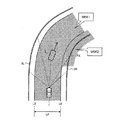
図6は、マスク領域MSKの第2の例を説明するための概念図である。マスク領域MSKの第2の例を、以下、便宜上、「第2マスク領域MSK2」と呼ぶ。第2マスク領域MSK2も、車線LAに関連しており、特に車線LAの方向から導き出される。 FIG. 6 is a conceptual diagram for explaining the second example of the mask region MSK. Hereinafter, the second example of the mask region MSK will be referred to as a “second mask region MSK2” for convenience. The second mask area MSK2 is also associated with the lane LA and is particularly derived from the direction of the lane LA.
より詳細には、車線LAの方向として、車線LAと路肩との間の境界である車線境界LBの方向を考える。図6に示されるように、車線境界LB上の点PL毎に角度θが定義される。角度θは、視線方向と接線方向とのなす角度である。視線方向は、第1センサ10あるいは第2センサ20から点PLへの方向である。接線方向は、点PLにおける車線境界LBの接線の方向である。マスク区間MSは、角度θが閾値θth未満である区間である。そして、第2マスク領域MSK2は、マスク区間MSの車線境界LBに沿った領域であって、車線境界LBからみて路肩側に位置する領域である。
More specifically, the direction of the lane LA is the direction of the lane boundary LB which is the boundary between the lane LA and the road shoulder. As shown in FIG. 6, the angle θ is defined for each point PL on the lane boundary LB. The angle θ is an angle formed by the line-of-sight direction and the tangential direction. The line-of-sight direction is the direction from the
図6から分かるように、上記のように定義された第2マスク領域MSK2は、反射率の低い道路構造物3(例えば、図2中の点PXを参照)をマスクすることができる可能性が高い。反射率の低い道路構造物3がマスクされると、推定精度の低下が防止される。 As can be seen from FIG. 6, the second mask region MSK2 defined as described above may be able to mask the road structure 3 having a low reflectance (for example, see the point PX in FIG. 2). high. When the road structure 3 having a low reflectance is masked, deterioration of estimation accuracy is prevented.
図7は、直線道路の場合の第2マスク領域MSK2の設定例を示している。図7に示される例では、第2マスク領域MSK2は、車両1から遠い位置の道路構造物3をマスクする。この場合も同様に、反射率の低い道路構造物3がマスクされ、推定精度の低下が防止される。
FIG. 7 shows a setting example of the second mask area MSK2 in the case of a straight road. In the example shown in FIG. 7, the second mask region MSK2 masks the road structure 3 located far from the
尚、第2マスク領域MSK2は、第1センサ10と第2センサ20とで異なっていてもよい。例えば、第1センサ10に関する第2マスク領域MSK2は、第1センサ10から点PLへの方向を視線方向として用いることにより定義される。第2センサ20に関する第2マスク領域MSK2は、第2センサ20から点PLへの方向を視線方向として用いることにより定義される。また、第1センサ10と第2センサ20とで閾値θthが異なっていてもよい。
The second mask region MSK2 may be different between the
図8は、図2で示された状況に第1マスク領域MSK1及び第2マスク領域MSK2が適用された場合を示している。第1マスク領域MSK1によって、車線LA内の移動物体がマスクされる。また、第2マスク領域MSK2によって、反射率の低い道路構造物3がマスクされる。すなわち、推定精度の低下を招く物体が軸ずれ推定処理から除外される。その結果、軸ずれ量δの推定精度が向上する。 FIG. 8 shows a case where the first mask region MSK1 and the second mask region MSK2 are applied to the situation shown in FIG. The moving object in the lane LA is masked by the first mask area MSK1. Further, the road structure 3 having a low reflectance is masked by the second mask area MSK2. That is, an object that causes a decrease in estimation accuracy is excluded from the axis deviation estimation process. As a result, the estimation accuracy of the axis deviation amount δ is improved.
本実施の形態によれば、第1マスク領域MSK1と第2マスク領域MSK2のうち少なくとも一方が、マスク領域MSKとして設定される。第1マスク領域MSK1と第2マスク領域MSK2のいずれか一方だけがマスク領域MSKとして設定される場合であっても、軸ずれ量δの推定精度が向上するという効果は得られる。 According to the present embodiment, at least one of first mask region MSK1 and second mask region MSK2 is set as mask region MSK. Even when only one of the first mask region MSK1 and the second mask region MSK2 is set as the mask region MSK, the effect of improving the estimation accuracy of the axis deviation amount δ can be obtained.
更に、第1センサ10の視野外の領域及び第2センサ20の視野外の領域が、マスク領域MSKとして設定されてもよい。
Further, the area outside the visual field of the
図9は、本実施の形態の効果を説明するための図であり、そのフォーマットは既出の図4と同じである。本実施の形態によれば、軸ずれ量δの推定精度が向上する。従って、推定される軸ずれ量δは安定し、そのばらつきは小さい。推定される軸ずれ量δが安定するため、信頼度の高い軸ずれ量δを早期に確定することが可能となる。その結果、車両1の自動運転を開始することができるまでの時間が短縮される。
FIG. 9 is a diagram for explaining the effect of the present embodiment, and its format is the same as that of FIG. 4 already described. According to the present embodiment, the estimation accuracy of the axis deviation amount δ is improved. Therefore, the estimated axis deviation amount δ is stable and its variation is small. Since the estimated axis deviation amount δ is stable, it is possible to quickly determine the axis deviation amount δ with high reliability. As a result, the time until the automatic driving of the
以下、本実施の形態に係る軸ずれ推定処理を実現する軸ずれ推定装置について説明する。 Hereinafter, an axis deviation estimation device that realizes the axis deviation estimation process according to the present embodiment will be described.
3.軸ずれ推定装置
3−1.構成例
図10は、本実施の形態に係る軸ずれ推定装置100の構成例を示すブロック図である。軸ずれ推定装置100は、例えば、車両1に搭載されている。軸ずれ推定装置100は、第1センサ10による認識結果を示す第1認識情報D10を、第1センサ10から受け取る。また、軸ずれ推定装置100は、第2センサ20による認識結果を示す第2認識情報D20を、第2センサ20から受け取る。
3. Axis deviation estimation device 3-1. Configuration Example FIG. 10 is a block diagram showing a configuration example of the axis
軸ずれ推定装置100は、第1認識情報D10及び第2認識情報D20に基づいて、軸ずれ推定処理を行う。より詳細には、軸ずれ推定装置100は、プロセッサ110、記憶装置120、及び運転環境取得装置130を備えている。
The axis
プロセッサ110は、軸ずれ推定処理を含む各種処理を実行する。例えば、プロセッサ110は、車両1の自動運転を制御するコントローラ(ECU: Electronic Control Unit)に含まれている。プロセッサ110が記憶装置120に格納された制御プログラムを実行することにより、プロセッサ110による各種処理が実現される。
The
記憶装置120には、第1認識情報D10、第2認識情報D20、車線情報D30、及び運転環境情報D130が格納される。第1認識情報D10は、第1センサ10による認識結果を示す。第2認識情報D20は、第2センサ20による認識結果を示す。車線情報D30は、車両1の周囲の車線LAの配置を示す。車線LAの配置とは、車線LAの位置、形状、幅、等を含む概念である。運転環境情報D130は、車両1の運転環境を示す。
The
運転環境取得装置130は、運転環境情報D130を取得する運転環境取得処理を行う。運転環境取得処理を行うプロセッサは、上記のプロセッサ110と同じであってもよいし、別であってもよい。
The driving
図11は、運転環境取得装置130と運転環境情報D130の例を示している。運転環境取得装置130は、車両位置センサ131、周辺状況センサ132、地図データベース133、及び通信装置134を含んでいる。運転環境情報D130は、車両位置情報D131、周辺状況情報D132、及び地図情報D133を含んでいる。
FIG. 11 shows an example of the driving
車両位置センサ131は、車両1の位置及び方位を検出し、車両1の位置及び方位を示す車両位置情報D131を取得する。例えば、車両位置センサ131は、GPS(Global Positioning System)センサを含む。GPSセンサは、複数のGPS衛星から送信される信号を受信し、受信信号に基づいて車両1の位置及び方位を算出する。
The
周辺状況センサ132は、車両1の周囲の状況を検出し、車両1の周囲の状況を示す周辺状況情報D132を取得する。例えば、周辺状況センサ132は、カメラ、ライダー、及びレーダのうち少なくとも1つを含んでいる。周辺状況センサ132は、第1センサ10や第2センサ20と同じであってもよい。周辺状況情報D132は、カメラによる撮像結果を示す撮像情報、ライダーやレーダによる計測結果を示す計測情報のうち少なくとも一方を含んでいる。
The surrounding
地図データベース133には、地図情報D133が記録されている。地図情報D133は、車線LAの配置に関する情報を含んでいる。運転環境取得装置130は、必要な範囲の地図情報D133を地図データベース133から取得する。地図データベース133が車両1の外部の管理サーバに格納されている場合、運転環境取得装置130は、通信装置134を介して管理サーバと通信を行い、管理サーバから必要な範囲の地図情報D133を取得する。
The
尚、地図情報D133が道路上の特徴物(例:白線、看板、ポール)の位置を含んでいる場合、運転環境取得装置130は、運転環境情報D130に基づいて周知の自己位置推定処理(localization)を行ってもよい。自己位置推定処理により、車両位置情報D131の精度が向上する。
In addition, when the map information D133 includes the position of the characteristic object (eg, white line, signboard, pole) on the road, the driving
3−2.処理フロー
図12は、本実施の形態に係る軸ずれ推定装置100のプロセッサ110による処理を示すフローチャートである。図12に示される処理は、一定サイクル毎に繰り返し実行される。
3-2. Processing Flow FIG. 12 is a flowchart showing processing by the
ステップS10において、プロセッサ110は、第1センサ10から第1認識情報D10を取得する。また、プロセッサ110は、第2センサ20から第2認識情報D20を取得する。また、プロセッサ110は、運転環境取得装置130から運転環境情報D130を取得する。プロセッサ110は、取得した情報を記憶装置120に格納する。
In step S10, the
ステップS20において、プロセッサ110は、車両1の周囲の車線LAの配置を示す車線情報D30を取得する。より詳細には、プロセッサ110は、運転環境情報D130に基づいて車線情報D30を取得する。
In step S20, the
例えば、地図情報D133は、車線LAの配置に関する情報を含んでいる。従って、プロセッサ110は、車両位置情報D131に基づいて車両1の周辺の地図情報D133を取得し、その地図情報D133から車線情報D30を取得することができる。
For example, the map information D133 includes information on the arrangement of the lane LA. Therefore, the
他の例として、プロセッサ110は、周辺状況情報D132(撮像情報や計測情報)に基づいて、車両1の周囲の白線を認識してもよい。この場合、プロセッサ110は、認識された白線の位置から車線LAの配置を推定し、車線情報D30を取得する。
As another example, the
ステップS30において、プロセッサ110は、車線情報D30に基づいて、車線LAに関連するマスク領域MSKの設定を行う。マスク領域MSKは、第1マスク領域MSK1(図5参照)と第2マスク領域MSK2(図6、図7参照)のうち少なくとも一方を含む。
In step S30, the
ステップS40において、プロセッサ110は、マスク領域MSK以外の第1認識情報D10及び第2認識情報D20に基づいて、軸ずれ量δを推定する。
In step S40, the
より詳細には、プロセッサ110は、第1認識情報D10及び第2認識情報D20に基づいて、マスク領域MSK以外の領域に存在する物体を抽出する。つまり、プロセッサ110は、物体抽出範囲からマスク領域MSKを除外することによって、物体抽出範囲を限定する。
More specifically, the
そして、プロセッサ110は、第1センサ10による物体認識結果と第2センサ20による物体認識結果とを対比することによって、軸ずれ量δを推定する。例えば、図3で示されたように、第1点群PC1と第2点群PC2との間の位置誤差が最小となるように、第1座標系と第2座標系の少なくとも一方の座標変換が行われる。位置誤差が最小となる場合の第1座標系と第2座標系との間の角度が、軸ずれ量δとして推定される。
Then, the
ステップS50において、プロセッサ110は、所定の確定条件が成立するか否かを判定する。例えば、確定条件は、一定期間において推定された複数の軸ずれ量δの分散σ2が閾値未満になることである。確定条件が成立しない場合(ステップS50;No)、今回のサイクルにおける処理は終了する。確定条件が成立する場合(ステップS50;Yes)、処理はステップS60に進む。
In step S50, the
ステップS60において、プロセッサ110は、軸ずれ量δを決定する。例えば、プロセッサ110は、一定期間において推定された複数の軸ずれ量δの平均値μを、軸ずれ量δとして決定する。
In step S60, the
1 車両
2 他車両
3、3L、3R 道路構造物
10 第1センサ
20 第2センサ
100 軸ずれ推定装置
110 プロセッサ
120 記憶装置
130 運転環境取得装置
131 車両位置センサ
132 周辺状況センサ
133 地図データベース
134 通信装置
D10 第1認識情報
D20 第2認識情報
D30 車線情報
D130 運転環境情報
D131 車両位置情報
D132 周辺状況情報
D133 地図情報
LA 車線(走路)
LB 車線境界
MSK マスク領域
MSK1 第1マスク領域
MSK2 第2マスク領域
1 vehicle 2
LB lane boundary MSK Mask area MSK1 1st mask area MSK2 2nd mask area
Claims (1)
前記第1センサと前記第2センサは、前記車両の周囲の状況を認識し、且つ、それぞれの視野は少なくとも部分的に重なっており、
前記軸ずれ推定装置は、
前記第1センサによる認識結果を示す第1認識情報と、前記第2センサによる認識結果を示す第2認識情報と、前記車両の周囲の車線の配置を示す車線情報と、が格納される記憶装置と、
前記軸ずれ量を推定するプロセッサと
を備え、
前記プロセッサは、
前記車線情報に基づいて、前記車線内の領域と前記車線の方向から導き出される領域のうち少なくとも一方を、マスク領域として設定し、
前記第1認識情報及び前記第2認識情報に基づいて、前記マスク領域以外の領域に存在する物体を抽出し、
前記第1センサによる前記物体の認識結果と前記第2センサによる前記物体の認識結果とを対比することによって、前記軸ずれ量を推定する
軸ずれ推定装置。 An axis deviation estimating device for estimating an axis deviation amount between a first sensor and a second sensor mounted on a vehicle,
The first sensor and the second sensor recognize a situation around the vehicle, and their respective visual fields at least partially overlap,
The axis deviation estimating device,
A storage device that stores first recognition information indicating a recognition result by the first sensor, second recognition information indicating a recognition result by the second sensor, and lane information indicating an arrangement of lanes around the vehicle. When,
And a processor that estimates the amount of axis deviation,
The processor is
Based on the lane information, at least one of the area in the lane and the area derived from the direction of the lane is set as a mask area,
An object existing in a region other than the mask region is extracted based on the first recognition information and the second recognition information,
An axis deviation estimating device for estimating the axis deviation amount by comparing a recognition result of the object by the first sensor and a recognition result of the object by the second sensor.
Priority Applications (1)
| Application Number | Priority Date | Filing Date | Title |
|---|---|---|---|
| JP2018208319A JP2020076580A (en) | 2018-11-05 | 2018-11-05 | Axial deviation estimation device |
Applications Claiming Priority (1)
| Application Number | Priority Date | Filing Date | Title |
|---|---|---|---|
| JP2018208319A JP2020076580A (en) | 2018-11-05 | 2018-11-05 | Axial deviation estimation device |
Publications (1)
| Publication Number | Publication Date |
|---|---|
| JP2020076580A true JP2020076580A (en) | 2020-05-21 |
Family
ID=70725008
Family Applications (1)
| Application Number | Title | Priority Date | Filing Date |
|---|---|---|---|
| JP2018208319A Pending JP2020076580A (en) | 2018-11-05 | 2018-11-05 | Axial deviation estimation device |
Country Status (1)
| Country | Link |
|---|---|
| JP (1) | JP2020076580A (en) |
Cited By (2)
| Publication number | Priority date | Publication date | Assignee | Title |
|---|---|---|---|---|
| JP2020530555A (en) * | 2017-07-26 | 2020-10-22 | ロベルト・ボッシュ・ゲゼルシャフト・ミト・ベシュレンクテル・ハフツングRobert Bosch Gmbh | Devices and methods for recognizing the position of an object |
| WO2022071315A1 (en) * | 2020-09-30 | 2022-04-07 | 学校法人明治大学 | Autonomous moving body control device, autonomous moving body control method, and program |
-
2018
- 2018-11-05 JP JP2018208319A patent/JP2020076580A/en active Pending
Cited By (3)
| Publication number | Priority date | Publication date | Assignee | Title |
|---|---|---|---|---|
| JP2020530555A (en) * | 2017-07-26 | 2020-10-22 | ロベルト・ボッシュ・ゲゼルシャフト・ミト・ベシュレンクテル・ハフツングRobert Bosch Gmbh | Devices and methods for recognizing the position of an object |
| US11313961B2 (en) | 2017-07-26 | 2022-04-26 | Robert Bosch Gmbh | Method and device for identifying the height of an object |
| WO2022071315A1 (en) * | 2020-09-30 | 2022-04-07 | 学校法人明治大学 | Autonomous moving body control device, autonomous moving body control method, and program |
Similar Documents
| Publication | Publication Date | Title |
|---|---|---|
| Levinson et al. | Automatic online calibration of cameras and lasers. | |
| US10140526B2 (en) | Object detecting device | |
| CN108692719B (en) | Object detection device | |
| US20200042803A1 (en) | Information processing method, information processing apparatus, and recording medium | |
| US10422871B2 (en) | Object recognition apparatus using a plurality of object detecting means | |
| KR102103944B1 (en) | Distance and position estimation method of autonomous vehicle using mono camera | |
| JP6458651B2 (en) | Road marking detection device and road marking detection method | |
| US11538241B2 (en) | Position estimating device | |
| JP4052291B2 (en) | Image processing apparatus for vehicle | |
| CA2994652C (en) | Step detection device and step detection method | |
| US10338211B2 (en) | Apparatus for measuring distance | |
| JP2020076580A (en) | Axial deviation estimation device | |
| KR102343020B1 (en) | Apparatus for calibrating position signal of autonomous vehicle using road surface image information | |
| US11914028B2 (en) | Object detection device for vehicle | |
| JP2023068009A (en) | Map information creation method | |
| WO2019151110A1 (en) | Road surface information acquisition method | |
| US20180225526A1 (en) | Step Detection Device and Step Detection Method | |
| EP3288260B1 (en) | Image processing device, imaging device, equipment control system, equipment, image processing method, and carrier means | |
| EP3435286A1 (en) | Imaging control device and imaging control method | |
| US11935256B1 (en) | Remote distance estimation system and method | |
| US11538252B2 (en) | Object recognition device | |
| WO2019151109A1 (en) | Road surface information acquisition method | |
| CN114137563B (en) | Locomotive and locomotive positioning method, device, equipment and storage medium | |
| JP7325296B2 (en) | Object recognition method and object recognition system | |
| US9972098B1 (en) | Remote distance estimation system and method |