JP2020072425A - Terminal device, base station device, and communication method - Google Patents
Terminal device, base station device, and communication method Download PDFInfo
- Publication number
- JP2020072425A JP2020072425A JP2018206556A JP2018206556A JP2020072425A JP 2020072425 A JP2020072425 A JP 2020072425A JP 2018206556 A JP2018206556 A JP 2018206556A JP 2018206556 A JP2018206556 A JP 2018206556A JP 2020072425 A JP2020072425 A JP 2020072425A
- Authority
- JP
- Japan
- Prior art keywords
- pucch
- resource
- format
- parameter
- terminal device
- Prior art date
- Legal status (The legal status is an assumption and is not a legal conclusion. Google has not performed a legal analysis and makes no representation as to the accuracy of the status listed.)
- Pending
Links
Images

Classifications
-
- H—ELECTRICITY
- H04—ELECTRIC COMMUNICATION TECHNIQUE
- H04L—TRANSMISSION OF DIGITAL INFORMATION, e.g. TELEGRAPHIC COMMUNICATION
- H04L5/00—Arrangements affording multiple use of the transmission path
- H04L5/003—Arrangements for allocating sub-channels of the transmission path
- H04L5/0053—Allocation of signaling, i.e. of overhead other than pilot signals
-
- H—ELECTRICITY
- H04—ELECTRIC COMMUNICATION TECHNIQUE
- H04W—WIRELESS COMMUNICATION NETWORKS
- H04W72/00—Local resource management
- H04W72/20—Control channels or signalling for resource management
- H04W72/21—Control channels or signalling for resource management in the uplink direction of a wireless link, i.e. towards the network
-
- H—ELECTRICITY
- H04—ELECTRIC COMMUNICATION TECHNIQUE
- H04L—TRANSMISSION OF DIGITAL INFORMATION, e.g. TELEGRAPHIC COMMUNICATION
- H04L1/00—Arrangements for detecting or preventing errors in the information received
- H04L1/12—Arrangements for detecting or preventing errors in the information received by using return channel
- H04L1/16—Arrangements for detecting or preventing errors in the information received by using return channel in which the return channel carries supervisory signals, e.g. repetition request signals
- H04L1/1607—Details of the supervisory signal
- H04L1/1671—Details of the supervisory signal the supervisory signal being transmitted together with control information
-
- H—ELECTRICITY
- H04—ELECTRIC COMMUNICATION TECHNIQUE
- H04L—TRANSMISSION OF DIGITAL INFORMATION, e.g. TELEGRAPHIC COMMUNICATION
- H04L1/00—Arrangements for detecting or preventing errors in the information received
- H04L1/12—Arrangements for detecting or preventing errors in the information received by using return channel
- H04L1/16—Arrangements for detecting or preventing errors in the information received by using return channel in which the return channel carries supervisory signals, e.g. repetition request signals
- H04L1/18—Automatic repetition systems, e.g. Van Duuren systems
- H04L1/1829—Arrangements specially adapted for the receiver end
- H04L1/1858—Transmission or retransmission of more than one copy of acknowledgement message
-
- H—ELECTRICITY
- H04—ELECTRIC COMMUNICATION TECHNIQUE
- H04L—TRANSMISSION OF DIGITAL INFORMATION, e.g. TELEGRAPHIC COMMUNICATION
- H04L1/00—Arrangements for detecting or preventing errors in the information received
- H04L1/12—Arrangements for detecting or preventing errors in the information received by using return channel
- H04L1/16—Arrangements for detecting or preventing errors in the information received by using return channel in which the return channel carries supervisory signals, e.g. repetition request signals
- H04L1/18—Automatic repetition systems, e.g. Van Duuren systems
- H04L1/1829—Arrangements specially adapted for the receiver end
- H04L1/1861—Physical mapping arrangements
-
- H—ELECTRICITY
- H04—ELECTRIC COMMUNICATION TECHNIQUE
- H04L—TRANSMISSION OF DIGITAL INFORMATION, e.g. TELEGRAPHIC COMMUNICATION
- H04L27/00—Modulated-carrier systems
- H04L27/26—Systems using multi-frequency codes
-
- H—ELECTRICITY
- H04—ELECTRIC COMMUNICATION TECHNIQUE
- H04W—WIRELESS COMMUNICATION NETWORKS
- H04W72/00—Local resource management
- H04W72/04—Wireless resource allocation
- H04W72/044—Wireless resource allocation based on the type of the allocated resource
- H04W72/0446—Resources in time domain, e.g. slots or frames
-
- H—ELECTRICITY
- H04—ELECTRIC COMMUNICATION TECHNIQUE
- H04L—TRANSMISSION OF DIGITAL INFORMATION, e.g. TELEGRAPHIC COMMUNICATION
- H04L1/00—Arrangements for detecting or preventing errors in the information received
- H04L1/0001—Systems modifying transmission characteristics according to link quality, e.g. power backoff
- H04L1/0023—Systems modifying transmission characteristics according to link quality, e.g. power backoff characterised by the signalling
- H04L1/0026—Transmission of channel quality indication
-
- H—ELECTRICITY
- H04—ELECTRIC COMMUNICATION TECHNIQUE
- H04L—TRANSMISSION OF DIGITAL INFORMATION, e.g. TELEGRAPHIC COMMUNICATION
- H04L5/00—Arrangements affording multiple use of the transmission path
- H04L5/003—Arrangements for allocating sub-channels of the transmission path
- H04L5/0053—Allocation of signaling, i.e. of overhead other than pilot signals
- H04L5/0055—Physical resource allocation for ACK/NACK
-
- H—ELECTRICITY
- H04—ELECTRIC COMMUNICATION TECHNIQUE
- H04L—TRANSMISSION OF DIGITAL INFORMATION, e.g. TELEGRAPHIC COMMUNICATION
- H04L5/00—Arrangements affording multiple use of the transmission path
- H04L5/003—Arrangements for allocating sub-channels of the transmission path
- H04L5/0053—Allocation of signaling, i.e. of overhead other than pilot signals
- H04L5/0057—Physical resource allocation for CQI
Abstract
Description
本発明は、端末装置、基地局装置、および、通信方法に関する。 The present invention relates to a terminal device, a base station device, and a communication method.
セルラー移動通信の無線アクセス方式および無線ネットワーク(以下、「Long Term Evolution (LTE:登録商標)」、または、「Evolved Universal Terrestrial Radio Access : EUTRA」と称する。)が、第三世代パートナーシッププロジェクト(3rd Generation Partnership Project: 3GPP)において検討されている。また、3GPPにおいて、新た
な無線アクセス方式(以下、「New Radio(NR)」と称する。)が検討されている(非特
許文献1、2、3、4)。LTEでは、基地局装置をeNodeB(evolved NodeB)と
も称する。NRでは、基地局装置をgNodeBとも称する。LTE、および、NRでは、端末装置をUE(User Equipment)とも称する。LTE、および、NRは、基地局装置がカバーするエリアをセル状に複数配置するセルラー通信システムである。単一の基地局装置は複数のセルを管理してもよい。
The wireless access method and wireless network of cellular mobile communication (hereinafter, referred to as “Long Term Evolution (LTE: registered trademark)” or “Evolved Universal Terrestrial Radio Access: EUTRA”) is a third generation partnership project (3rd Generation). Partnership Project: 3GPP). In 3GPP, a new radio access scheme (hereinafter referred to as “New Radio (NR)”) is under study (
NRにおいて、1つのサービングセルに対して下りリンクBWP(bandwidth part)と上りリンクBWPのセットが設定される(非特許文献3)。端末装置は、下りリンクBWPにおいてPDCCHとPDSCHを受信する。 In NR, a set of downlink BWP (bandwidth part) and uplink BWP is set for one serving cell (Non-Patent Document 3). The terminal device receives the PDCCH and PDSCH in the downlink BWP.
本発明は、効率的に通信を行うことができる端末装置、該端末装置に用いられる通信方法、効率的に通信を行うことができる基地局装置、および、該基地局装置に用いられる通信方法を提供する。 The present invention provides a terminal device capable of efficient communication, a communication method used for the terminal device, a base station device capable of efficient communication, and a communication method used for the base station device. provide.
(1)本発明の第1の態様は、端末装置であって、複数のPUCCHリソースのオーバーラップを解決する処理部と、前記処理部の出力であるPUCCHを送信する送信部と、を備え、前記処理部は、第1のPUCCHリソースと第2のPUCCHリソースがオーバーラップする場合、前記第1のPUCCHリソースに含まれる第1のUCIと前記第2のPUCCHリソースに含まれる第2のUCIを第3のPUCCHリソースに多重し、前記第1のPUCCHリソースの第1のPUCCHフォーマットに対する第1のパラメータNPUCCH repeatおよび前記第2のPUCCHリソースの第2のPUCCHフォーマットに対する第2のパラメータNPUCCH repeatが、前記第3のPUCCHリ
ソースの第3のPUCCHフォーマットに対する第3のパラメータNPUCCH repeatと同じであることが期待され、前記第1のパラメータNPUCCH repeatは、前記第1のPUCCHフォーマットの前記第1のPUCCHリソースが繰り返されるスロットの数に関連し、前記第2のパラメータNPUCCH repeatは、前記第1のPUCCHフォーマットの前記第1のPUCCHリソースが繰り返されるスロットの数に関連し、前記第3のパラメータNPUCCH repeatは、前記第1のPUCCHフォーマットの前記第1のPUCCHリソースが繰り返されるスロットの数に関連し、前記第3のPUCCHフォーマットは、前記第1のPUCCHフォーマットおよび前記第2のPUCCHフォーマットと異なる。
(1) A first aspect of the present invention is a terminal device, which includes a processing unit that resolves overlap of a plurality of PUCCH resources, and a transmission unit that transmits a PUCCH that is an output of the processing unit, The processing unit, when the first PUCCH resource and the second PUCCH resource overlap, a first UCI included in the first PUCCH resource and a second UCI included in the second PUCCH resource. Multiplexed on a third PUCCH resource, a first parameter N PUCCH repeat for the first PUCCH format of the first PUCCH resource and a second parameter N PUCCH repeat for the second PUCCH format of the second PUCCH resource. Is the third PUCCH resource of the third PUCCH resource. It is expected to be the same as the third parameter N PUCCH repeat for the format, said first parameter N PUCCH repeat being related to the number of slots in which said first PUCCH resource of said first PUCCH format is repeated. , The second parameter N PUCCH repeat is related to the number of slots in which the first PUCCH resource of the first PUCCH format is repeated, and the third parameter N PUCCH repeat is the first PUCCH format. The third PUCCH format is different from the first PUCCH format and the second PUCCH format in relation to the number of slots in which the first PUCCH resource is repeated.
(2)本発明の第2の態様は、基地局装置であって、複数のPUCCHリソースのオーバーラップを解決する処理部と、前記処理部の出力であるPUCCHを受信する受信部と、を備え、前記処理部は、第1のPUCCHリソースと第2のPUCCHリソースがオーバーラップする場合、前記第1のPUCCHリソースに含まれる第1のUCIと前記第2のPUCCHリソースに含まれる第2のUCIを第3のPUCCHリソースに多重し、前記第1のPUCCHリソースの第1のPUCCHフォーマットに対する第1のパラメータNPUCCH repeatおよび前記第2のPUCCHリソースの第2のPUCCHフォーマットに対する第2のパラメータNPUCCH repeatが、前記第3のPUCCHリソースの第3のPUCCHフォーマットに対する第3のパラメータNPUCCH repeatと同じく設定し、前記第1のパラメータNPUCCH repeatは、前記第1のPUCCHフォーマットの前記第1のPUCCHリソースが繰り返されるスロットの数に関連し、前記第2のパラメータNPUCCH repeatは、前記第1のPUCCHフォーマットの前記第1のPUCCHリソースが繰り返されるスロットの数に関連し、前記第3のパラメータNPUCCH repeatは、前記第1のPUCCHフォーマットの前記第1のPUCCHリソースが繰り返されるスロットの数に関連し、前記第3のPUCCHフォーマットは、前記第1のPUCCHフォーマットおよび前記第2のPUCCHフォーマットと異なる。 (2) A second aspect of the present invention is a base station apparatus, which includes a processing unit that resolves overlap of a plurality of PUCCH resources, and a receiving unit that receives the PUCCH that is the output of the processing unit. If the first PUCCH resource and the second PUCCH resource overlap, the processing unit includes a first UCI included in the first PUCCH resource and a second UCI included in the second PUCCH resource. To a third PUCCH resource, and a first parameter N PUCCH repeat for the first PUCCH format of the first PUCCH resource and a second parameter N PUCCH for the second PUCCH format of the second PUCCH resource. repeat is the third PUCCH of the third PUCCH resource Set the same as the third parameter N PUCCH repeat for the format, said first parameter N PUCCH repeat is related to the number of slots in which said first PUCCH resource of said first PUCCH format is repeated, said second parameter Parameter N PUCCH repeat is related to the number of slots in which the first PUCCH resource of the first PUCCH format is repeated and the third parameter N PUCCH repeat is the first PUCCH format of the first PUCCH format. Of PUCCH resources are related to the number of repeated slots, the third PUCCH format is different from the first PUCCH format and the second PUCCH format.
(3)本発明の第7の態様は、端末装置に用いられる通信方法であって、複数のPUCCHリソースのオーバーラップを解決するステップと、前記処理部の出力であるPUCCHを送信するステップと、を備え、前記処理ステップは、第1のPUCCHリソースと第2のPUCCHリソースがオーバーラップする場合、前記第1のPUCCHリソースに含まれる第1のUCIと前記第2のPUCCHリソースに含まれる第2のUCIを第3のPUCCHリソースに多重し、前記第1のPUCCHリソースの第1のPUCCHフォーマットに対する第1のパラメータNPUCCH repeatおよび前記第2のPUCCHリソースの第2のPUCCHフォーマットに対する第2のパラメータNPUCCH repeatが、前記第3のPUCCHリソースの第3のPUCCHフォーマットに対する第3のパラメータNPUCCH repeatと同じであることが期待され、前記第1のパラメータNPUCCH repeatは、前記第1のPUCCHフォーマットの前記第1のPUCCHリソースが繰り返されるスロットの数に関連し、前記第2のパラメータNPUCCH repeatは、前記第1のPUCCHフォーマットの前記第1のPUCCHリソースが繰り返されるスロットの数に関連し、前記第3のパラメータNPUCCH repeatは、前記第1のPUCCHフォーマットの前記第1のPUCCHリソースが繰り返されるスロットの数に関連し、前記第3のPUCCHフォーマットは、前記第1のPUCCHフォーマットおよび前記第2のPUCCHフォーマットと異なる。 (3) A seventh aspect of the present invention is a communication method used in a terminal device, wherein a step of solving an overlap of a plurality of PUCCH resources, a step of transmitting a PUCCH that is an output of the processing unit, And the first PUCCH resource included in the first PUCCH resource and the second PUCCH resource included in the second PUCCH resource when the first PUCCH resource and the second PUCCH resource overlap. UCI of the first PUCCH resource is multiplexed into a third PUCCH resource, and a first parameter N PUCCH repeat for the first PUCCH format of the first PUCCH resource and a second parameter of the second PUCCH format for the second PUCCH resource. N PUCCH repeat is the third PUCC It is expected to be the same as the third parameter N PUCCH repeat for the third PUCCH format of the H resource, said first parameter N PUCCH repeat being repeated by said first PUCCH resource of said first PUCCH format. The second parameter N PUCCH repeat is related to the number of slots in which the first PUCCH resource of the first PUCCH format is repeated, and the third parameter N PUCCH repeat is , The third PUCCH format is related to the number of slots in which the first PUCCH resource of the first PUCCH format is repeated, and the third PUCCH format is the first PUCCH format and the second PUCCH format. Different.
(3)本発明の第7の態様は、基地局装置に用いられる通信方法であって、複数のPUCCHリソースのオーバーラップを解決する処理ステップと、前記処理部の出力であるPUCCHを送信するステップと、を備え、前記処理ステップは、第1のPUCCHリソースと第2のPUCCHリソースがオーバーラップする場合、前記第1のPUCCHリソー
スに含まれる第1のUCIと前記第2のPUCCHリソースに含まれる第2のUCIを第3のPUCCHリソースに多重し、前記第1のPUCCHリソースの第1のPUCCHフォーマットに対する第1のパラメータNPUCCH repeatおよび前記第2のPUCCHリソースの第2のPUCCHフォーマットに対する第2のパラメータNPUCCH repeatが、前記第3のPUCCHリソースの第3のPUCCHフォーマットに対する第3のパラメータNPUCCH repeatと同じであることが期待され、前記第1のパラメータNPUCCH repeatは、前記第1のPUCCHフォーマットの前記第1のPUCCHリソースが繰り返されるスロットの数に関連し、前記第2のパラメータNPUCCH repeatは、前記第1のPUCCHフォーマットの前記第1のPUCCHリソースが繰り返されるスロットの数に関連し、前記第3のパラメータNPUCCH repeatは、前記第1のPUCCHフォーマットの前記第1のPUCCHリソースが繰り返されるスロットの数に関連し、前記第3のPUCCHフォーマットは、前記第1のPUCCHフォーマットおよび前記第2のPUCCHフォーマットと異なる。
(3) A seventh aspect of the present invention is a communication method used in a base station device, comprising: a processing step of solving an overlap of a plurality of PUCCH resources; and a step of transmitting a PUCCH output from the processing unit. And the processing step is included in the first UCI included in the first PUCCH resource and the second PUCCH resource when the first PUCCH resource and the second PUCCH resource overlap. A second UCI is multiplexed on a third PUCCH resource, a first parameter N PUCCH repeat for the first PUCCH format of the first PUCCH resource and a second parameter PUCCH format for the second PUCCH resource. Parameter N PUCCH repeat of the third P Expected to be the same as the third parameter N PUCCH repeat for the third PUCCH format of the UCCH resource, said first parameter N PUCCH repeat being a repeat of said first PUCCH resource of said first PUCCH format. The second parameter N PUCCH repeat is related to the number of slots in which the first PUCCH resource of the first PUCCH format is repeated, and the third parameter N PUCCH repeat is , The third PUCCH format is related to the number of slots in which the first PUCCH resource of the first PUCCH format is repeated, and the third PUCCH format is the first PUCCH format and the second PUCCH format. Tsu door is different.
この発明によれば、端末装置は効率的に通信を行うことができる。また、基地局装置は効率的に通信を行うことができる。 According to the present invention, the terminal device can efficiently perform communication. In addition, the base station device can efficiently perform communication.
以下、本発明の実施形態について説明する。 Hereinafter, embodiments of the present invention will be described.
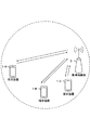
図1は、本実施形態の無線通信システムの概念図である。図1において、無線通信システムは、端末装置1A〜1C、および基地局装置3を具備する。以下、端末装置1A〜1Cを端末装置1という。
FIG. 1 is a conceptual diagram of a wireless communication system of this embodiment. In FIG. 1, the wireless communication system includes terminal devices 1A to 1C and a
基地局装置3は、MCG(Master Cell Group)、および、SCG(Secondary Cell Group)の一方または両方を含んで構成されてもよい。MCGは、少なくともPCell(Primary Cell)を含んで構成されるサービングセルのグループである。SCGは、少なく
ともPSCell(Primary Secondary Cell)を含んで構成されるサービングセルのグループである。PCellは、初期接続に基づき与えられるサービングセルであってもよい。MCGは、1または複数のSCell(Secondary Cell)を含んで構成されてもよい。SCGは、1または複数のSCellを含んで構成されてもよい。
The
MCGは、EUTRA上のサービングセルで構成されてもよい。SCGは、次世代規格
(NR: New Radio)上のサービングセルで構成されてもよい。
The MCG may be composed of a serving cell on EUTRA. The SCG may be composed of a serving cell on the next-generation standard (NR: New Radio).
以下、フレーム構成について説明する。 The frame structure will be described below.
本実施形態の一態様に係る無線通信システムにおいて、OFDM(Orthogonal Frequency Division Multiplex)が少なくとも用いられる。OFDMシンボルは、OFDMの時
間領域の単位である。OFDMシンボルは、少なくとも1または複数のサブキャリア(subcarrier)を含む。OFDMシンボルは、ベースバンド信号生成において時間連続信号(time―continuous signal)に変換される。下りリンクにおいて、CP−OFDM(Cyclic Prefix ― Orthogonal Frequency Division Multiplex)が少なくとも用いられる。上
りリンクにおいて、CP−OFDM、または、DFT−s−OFDM(Discrete Fourier
Transform ― spread ― Orthogonal Frequency Division Multiplex)のいずれかが用
いられる。DFT−s−OFDMは、CP−OFDMに対して変形プレコーディング(Transform precoding)が適用されることで与えられてもよい。
In the wireless communication system according to one aspect of the present embodiment, at least OFDM (Orthogonal Frequency Division Multiplex) is used. An OFDM symbol is a time domain unit of OFDM. An OFDM symbol includes at least one or more subcarriers. The OFDM symbol is converted into a time-continuous signal in baseband signal generation. In the downlink, at least CP-OFDM (Cyclic Prefix-Orthogonal Frequency Division Multiplex) is used. In the uplink, CP-OFDM or DFT-s-OFDM (Discrete Fourier
Transform ― spread ― Orthogonal Frequency Division Multiplex) is used. DFT-s-OFDM may be provided by applying a transform precoding to CP-OFDM.
OFDMシンボルは、該OFDMシンボルに付加されるCPを含んだ呼称であってもよい。つまり、あるOFDMシンボルは、該あるOFDMシンボルと、該あるOFDMシンボルに付加されるCPを含んで構成されてもよい。 The OFDM symbol may be a name including a CP added to the OFDM symbol. That is, a certain OFDM symbol may be configured to include the certain OFDM symbol and the CP added to the certain OFDM symbol.
サブキャリア間隔(SCS: SubCarrier Spacing)は、サブキャリア間隔Δf=2μ・1
5kHzによって与えられてもよい。例えば、サブキャリア間隔の設定(subcarrier spacing configuration)μは0、1、2、3、4、および/または、5のいずれかに設定されてもよい。あるBWP(BandWidth Part)のために、サブキャリア間隔の設定μが上位層のパラメータにより与えられてもよい。
The subcarrier spacing (SCS: SubCarrier Spacing) is the subcarrier spacing Δf = 2 μ · 1
May be given by 5 kHz. For example, the subcarrier spacing configuration μ may be set to any of 0, 1, 2, 3, 4, and / or 5. For a certain BWP (Band Width Part), the subcarrier spacing setting μ may be given by a higher layer parameter.
本実施形態の一態様に係る無線通信システムにおいて、時間領域の長さの表現のために時間単位(タイムユニット)Tcが用いられる。時間単位Tcは、Tc=1/(Δfmax・Nf)で与えられてもよい。Δfmaxは、本実施形態の一態様に係る無線通信システムにおいてサポートされるサブキャリア間隔の最大値であってもよい。Δfmaxは、Δfmax=480kHzであってもよい。Nfは、Nf=4096であってもよい。定数κは、κ=Δfmax・Nf/(ΔfrefNf,ref)=64である。Δfrefは、15kHzであってもよい。Nf,refは、2048であってもよい。 In the wireless communication system according to the aspect of the present embodiment, a time unit (time unit) T c is used for expressing the length of the time domain. The time unit T c may be given by T c = 1 / (Δf max · N f ). Δf max may be the maximum value of the subcarrier spacing supported in the wireless communication system according to the aspect of the present embodiment. Δf max may be Δf max = 480 kHz. N f may be N f = 4096. The constant κ is κ = Δf max · N f / (Δf ref N f, ref ) = 64. Δf ref may be 15 kHz. N f, ref may be 2048.
定数κは、参照サブキャリア間隔とTcの関係を示す値であってもよい。定数κはサブフレームの長さのために用いられてもよい。定数κに少なくとも基づき、サブフレームに含まれるスロットの数が与えられてもよい。Δfrefは、参照サブキャリア間隔であり、Nf,refは、参照サブキャリア間隔に対応する値である。 The constant κ may be a value indicating the relationship between the reference subcarrier interval and T c . The constant κ may be used for the subframe length. The number of slots included in the subframe may be given based at least on the constant κ. Δf ref is a reference subcarrier interval, and N f, ref is a value corresponding to the reference subcarrier interval.
下りリンクにおける信号の送信、および/または、上りリンクにおける信号の送信は、10msのフレームにより構成される。フレームは、10個のサブフレームを含んで構成される。サブフレームの長さは1msである。フレームの長さは、サブキャリア間隔Δfに関わらず与えられてもよい。つまり、フレームの設定はμに関わらず与えられてもよい。サブフレームの長さは、サブキャリア間隔Δfに関わらず与えられてもよい。つまり、サブフレームの設定はμに関わらず与えられてもよい。 Transmission of a signal on the downlink and / or transmission of a signal on the uplink is configured by a 10 ms frame. The frame is configured to include 10 subframes. The subframe length is 1 ms. The frame length may be given regardless of the subcarrier spacing Δf. That is, the frame setting may be given regardless of μ. The length of the subframe may be given regardless of the subcarrier spacing Δf. That is, the subframe setting may be given regardless of μ.
あるサブキャリア間隔の設定μのために、サブフレームに含まれるスロットの数とインデックスが与えられてもよい。例えば、スロット番号nμ sは、サブフレームにおいて0からNsubframe,μ slot−1の範囲で昇順に与えられてもよい。サブキャリア間隔の設定μのために、フレームに含まれるスロットの数とインデックスが与えられてもよい。また、スロット番号nμ s,fは、フレームにおいて0からNframe,μ s
lot−1の範囲で昇順に与えられてもよい。連続するNslot symb個のOFDMシンボルが1つのスロットに含まれてもよい。Nslot symbは、および/または、CP(Cyclic Prefix)設定の一部または全部に少なくとも基づき与えられてもよい。C
P設定は、上位層のパラメータに少なくとも基づき与えられてもよい。CP設定は、専用RRCシグナリングに少なくとも基づき与えられてもよい。スロット番号は、スロットインデックスとも呼称される。
For a certain setting μ of subcarrier spacing, the number and the index of slots included in a subframe may be given. For example, the slot number n μ s may be given in ascending order in the range of 0 to N subframe, μ slot −1 in the subframe . For the setting μ of the subcarrier spacing, the number of slots included in the frame and the index may be given. Further, slot numbers n μ s, f are 0 to N frame, μ s in the frame.
It may be given in ascending order in the range of lot −1. Consecutive N slot symb OFDM symbols may be included in one slot. N slot symb may be provided based on at least part of or all of CP (Cyclic Prefix) setting. C
The P setting may be given based at least on the upper layer parameters. CP settings may be provided based at least on dedicated RRC signaling. The slot number is also called a slot index.
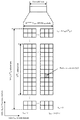
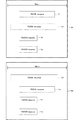
図2は、本実施形態の一態様に係るNslot symb、サブキャリア間隔の設定μ、および、CP設定の関係を示す一例である。図2Aにおいて、例えば、サブキャリア間隔の設定μが2であり、CP設定がノーマルCP(normal cyclic prefix)である場合、Nslot symb=14、Nframe,μ slot=40、Nsubframe,μ slot=4である。また、図2Bにおいて、例えば、サブキャリア間隔の設定μが2であり、CP設定が拡張CP(extended cyclic prefix)である場合、Nslot symb=12、Nframe,μ slot=40、Nsubframe,μ slot=4である。 FIG. 2 is an example showing a relationship between N slot symb , subcarrier interval setting μ, and CP setting according to an aspect of the present embodiment. In FIG. 2A, for example, when the subcarrier spacing setting μ is 2 and the CP setting is a normal CP (normal cyclic prefix), N slot symb = 14, N frame, μ slot = 40, N subframe, μ slot = 4. Further, in FIG. 2B, for example, when the subcarrier interval setting μ is 2 and the CP setting is extended CP (extended cyclic prefix), N slot symb = 12, N frame, μ slot = 40, N subframe, μ slot = 4.
以下、物理リソースについて説明を行う。 The physical resources will be described below.
アンテナポートは、1つのアンテナポートにおいてシンボルが伝達されるチャネルが、同一のアンテナポートにおいてその他のシンボルが伝達されるチャネルから推定できることによって定義される。1つのアンテナポートにおいてシンボルが伝達されるチャネルの大規模特性(large scale property)が、もう一つのアンテナポートにおいてシンボルが伝達されるチャネルから推定できる場合、2つのアンテナポートはQCL(Quasi Co-Located)であると呼称される。大規模特性は、チャネルの長区間特性を少なくとも含んでもよい。大規模特性は、遅延拡がり(delay spread)、ドップラー拡がり(Doppler spread)、ドップラーシフト(Doppler shift)、平均利得(average gain)、平均遅延(average delay)、および、ビームパラメータ(spatial Rx parameters)の一部または全部を
少なくとも含んでもよい。第1のアンテナポートと第2のアンテナポートがビームパラメータに関してQCLであるとは、第1のアンテナポートに対して受信側が想定する受信ビームと第2のアンテナポートに対して受信側が想定する受信ビームとが同一であることであってもよい。第1のアンテナポートと第2のアンテナポートがビームパラメータに関してQCLであるとは、第1のアンテナポートに対して受信側が想定する送信ビームと第2のアンテナポートに対して受信側が想定する送信ビームとが同一であることであってもよい。端末装置1は、1つのアンテナポートにおいてシンボルが伝達されるチャネルの大規模特性が、もう一つのアンテナポートにおいてシンボルが伝達されるチャネルから推定できる場合、2つのアンテナポートはQCLであることが想定されてもよい。2つのアンテナポートがQCLであることは、2つのアンテナポートがQCLであることが想定されることであってもよい。
An antenna port is defined by the fact that the channel carrying a symbol on one antenna port can be estimated from the channel carrying another symbol on the same antenna port. If the large scale property of the channel carrying the symbols on one antenna port can be estimated from the channel carrying the symbols on the other antenna port, the two antenna ports are QCL (Quasi Co-Located). ) Is called. The large-scale characteristic may include at least a long-term characteristic of the channel. Large-scale characteristics include delay spread, Doppler spread, Doppler shift, average gain, average delay, and beam parameters (spatial Rx parameters). Part or all may be included at least. The first antenna port and the second antenna port being QCL with respect to the beam parameters means that the receiving beam assumed by the receiving side for the first antenna port and the receiving beam assumed by the receiving side for the second antenna port. And may be the same. That the first antenna port and the second antenna port are QCL with respect to the beam parameters means that the transmission beam assumed by the reception side for the first antenna port and the transmission beam assumed by the reception side for the second antenna port. And may be the same. The
サブキャリア間隔の設定とキャリアのセットのために、Nsize,μ grid,xNRB sc個のサブキャリアとNsubframe,μ symb個のOFDMシンボルで定義されるリソースグリッドが与えられる。Nsize,μ grid,xは、キャリアxのためのサブキャリア間隔の設定μのために与えられるリソースブロック数を示してもよい。Nsize,μ grid,xは、キャリアの帯域幅を示してもよい。Nsize,μ grid,xは、上位層のパラメータCarrierBandwidthの値に対応してもよい。キャリアxは下りリンクキャリアまたは上りリンクキャリアのいずれかを示してもよい。つまり、xは“DL”、または、“UL”のいずれかであってもよい。NRB scは、1つのリソースブロックに含まれるサブキャリア数を示してもよい。NRB scは12であってもよい。アンテナポートpごとに、および/または、サブキャリア間隔の設定μごとに、および/または、送信方向(Transmission direction)の設定ごとに少なくとも1つのリソースグリッドが与えられてもよい。送信方向は、少なくとも下りリンク(DL
: DownLink)および上りリンク(UL: UpLink)を含む。以下、アンテナポートp、サブキャリア間隔の設定μ、および、送信方向の設定の一部または全部を少なくとも含むパラメータのセットは、第1の無線パラメータセットとも呼称される。つまり、リソースグリッドは、第1の無線パラメータセットごとに1つ与えられてもよい。
A resource grid defined by N size, μ grid, x N RB sc subcarriers and N subframe, μ symb OFDM symbols is provided for setting the subcarrier spacing and setting the carriers. N size, μ grid, x may indicate the number of resource blocks provided for setting μ of the subcarrier spacing for carrier x. N size, μ grid, x may indicate the bandwidth of the carrier. N size, μ grid, x may correspond to the value of the upper layer parameter CarrierBandwidth. Carrier x may indicate either a downlink carrier or an uplink carrier. That is, x may be either “DL” or “UL”. N RB sc may indicate the number of subcarriers included in one resource block. N RB sc may be 12. At least one resource grid may be provided per antenna port p and / or per subcarrier spacing setting μ and / or per transmission direction setting. At least the downlink (DL
: DownLink) and uplink (UL: UpLink). Hereinafter, the set of parameters including at least part or all of the antenna port p, the subcarrier spacing setting μ, and the setting of the transmission direction is also referred to as a first wireless parameter set. That is, one resource grid may be provided for each first wireless parameter set.
下りリンクにおいて、サービングセルに含まれるキャリアを下りリンクキャリア(または、下りリンクコンポーネントキャリア)と称する。上りリンクにおいて、サービングセルに含まれるキャリアを上りリンクキャリア(上りリンクコンポーネントキャリア)と称する。下りリンクコンポーネントキャリア、および、上りリンクコンポーネントキャリアを総称して、コンポーネントキャリア(または、キャリア)と称する。 In the downlink, a carrier included in a serving cell is called a downlink carrier (or downlink component carrier). In the uplink, a carrier included in the serving cell is called an uplink carrier (uplink component carrier). The downlink component carrier and the uplink component carrier are generically called a component carrier (or carrier).
サービングセルのタイプは、PCell、PSCell、および、SCellのいずれかであってもよい。PCellは、初期接続においてSS/PBCHから取得されるセルIDに少なくとも基づき識別されるサービングセルであってもよい。SCellは、キャリアアグリゲーションにおいて用いられるサービングセルであってもよい。SCellは、専用RRCシグナリングに少なくとも基づき与えられるサービングセルであってもよい。 The serving cell type may be any of PCell, PSCell, and SCell. The PCell may be a serving cell identified based on at least the cell ID acquired from the SS / PBCH in the initial connection. The SCell may be a serving cell used in carrier aggregation. The SCell may be a serving cell provided at least based on dedicated RRC signaling.
第1の無線パラメータセットごとに与えられるリソースグリッドの中の各要素は、リソースエレメントと呼称される。リソースエレメントは周波数領域のインデックスkscと、時間領域のインデックスlsymにより特定される。ある第1の無線パラメータセットのために、リソースエレメントは周波数領域のインデックスkscと、時間領域のインデックスlsymにより特定される。周波数領域のインデックスkscと時間領域のインデックスlsymにより特定されるリソースエレメントは、リソースエレメント(ksc、lsym)とも呼称される。周波数領域のインデックスkscは、0からNμ RBNRB sc−1のいずれかの値を示す。Nμ RBはサブキャリア間隔の設定μのために与えられるリソースブロック数であってもよい。Nμ RBは、Nsize,μ grid,xであってもよい。NRB scは、リソースブロックに含まれるサブキャリア数であり、NRB sc=12である。周波数領域のインデックスkscは、サブキャリアインデックスkscに対応してもよい。時間領域のインデックスlsymは、OFDMシンボルインデックスlsymに対応してもよい。 Each element in the resource grid provided for each first radio parameter set is called a resource element. The resource element is specified by the index ksc in the frequency domain and the index lsym in the time domain. For a certain first radio parameter set, the resource element is specified by the frequency domain index k sc and the time domain index l sym . The resource element specified by the frequency domain index k sc and the time domain index l sym is also referred to as a resource element (k sc , l sym ). Index k sc in the frequency domain represents any of the values of N μ RB N RB sc -1 0. N μ RB may be the number of resource blocks provided for setting μ of the subcarrier spacing. N μ RB may be N size, μ grid, x . N RB sc is the number of subcarriers included in the resource block, and N RB sc = 12. The frequency domain index ksc may correspond to the subcarrier index ksc . The time domain index l sym may correspond to the OFDM symbol index l sym .
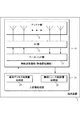
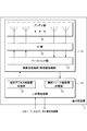
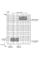
図3は、本実施形態の一態様に係るサブフレームにおけるリソースグリッドの一例を示す概略図である。図3のリソースグリッドにおいて、横軸は時間領域のインデックスlsymであり、縦軸は周波数領域のインデックスkscである。1つのサブフレームにおいて、リソースグリッドの周波数領域はNμ RBNRB sc個のサブキャリアを含む。1つのサブフレームにおいて、リソースグリッドの時間領域は14・2μ個のOFDMシンボルを含んでもよい。1つのリソースブロックは、NRB sc個のサブキャリアを含んで構成される。リソースブロックの時間領域は、1OFDMシンボルに対応してもよい。リソースブロックの時間領域は、14OFDMシンボルに対応してもよい。リソースブロックの時間領域は、1または複数のスロットに対応してもよい。リソースブロックの時間領域は、1つのサブフレームに対応してもよい。 FIG. 3 is a schematic diagram showing an example of a resource grid in a subframe according to an aspect of the present embodiment. In the resource grid of FIG. 3, the horizontal axis is the time domain index l sym , and the vertical axis is the frequency domain index k sc . In one subframe, the frequency domain of the resource grid includes N μ RB N RB sc subcarriers. In one subframe, the time domain of the resource grid may include 14.2 μ OFDM symbols. One resource block is configured to include N RB sc subcarriers. The time domain of the resource block may correspond to one OFDM symbol. The time domain of the resource block may correspond to 14 OFDM symbols. The time domain of the resource block may correspond to one or more slots. The time domain of the resource block may correspond to one subframe.
端末装置1は、リソースグリッドのサブセットのみを用いて送受信を行うことが指示されてもよい。リソースグリッドのサブセットは、BWPとも呼称され、BWPは上位層のパラメータ、および/または、DCIの一部または全部に少なくとも基づき与えられてもよい。BWPをキャリアバンドパート(Carrier Bandwidth Part)とも称する。端末装置1は、リソースグリッドのすべてのセットを用いて送受信を行なうことが指示されなくてもよい。端末装置1は、リソースグリッド内の一部の周波数リソースを用いて送受信を行なうことが指示されてもよい。1つのBWPは、周波数領域における複数のリソースブロ
ックから構成されてもよい。1つのBWPは、周波数領域において連続する複数のリソースブロックから構成されてもよい。下りリンクキャリアに対して設定されるBWPは、下りリンクBWPとも呼称される。上りリンクキャリアに対して設定されるBWPは、上りリンクBWPとも呼称される。BWPは、キャリアの帯域のサブセットであってもよい。
The
サービングセルのそれぞれに対して1または複数の下りリンクBWPが設定されてもよい。サービングセルのそれぞれに対して1または複数の上りリンクBWPが設定されてもよい。 One or more downlink BWPs may be set for each serving cell. One or more uplink BWPs may be configured for each serving cell.
サービングセルに対して設定される1または複数の下りリンクBWPのうち、1つの下りリンクBWPがアクティブ下りリンクBWPに設定されてもよい。下りリンクのBWPスイッチは、1つのアクティブ下りリンクBWPをディアクティベート(deactivate)し、該1つのアクティブ下りリンクBWP以外のインアクティブ下りリンクBWPをアクティベート(activate)するために用いられる。下りリンクのBWPスイッチは、下りリンク制御情報に含まれるBWPフィールドにより制御されてもよい。下りリンクのBWPスイッチは、上位層のパラメータに基づき制御されてもよい。 Of the one or more downlink BWPs set for the serving cell, one downlink BWP may be set as the active downlink BWP. The downlink BWP switch is used for deactivating one active downlink BWP and activating an inactive downlink BWP other than the one active downlink BWP. The downlink BWP switch may be controlled by the BWP field included in the downlink control information. The downlink BWP switch may be controlled based on upper layer parameters.
アクティブ下りリンクBWPにおいて、DL−SCHが受信されてもよい。アクティブ下りリンクBWPにおいて、PDCCHがモニタされてもよい。アクティブ下りリンクBWPにおいて、PDSCHが受信されてもよい。 The DL-SCH may be received in the active downlink BWP. The PDCCH may be monitored in the active downlink BWP. The PDSCH may be received in the active downlink BWP.
インアクティブ下りリンクBWPにおいて、DL−SCHが受信されない。インアクティブ下りリンクBWPにおいて、PDCCHがモニタされない。インアクティブ下りリンクBWPのためのCSIは報告されない。 The DL-SCH is not received in the inactive downlink BWP. The PDCCH is not monitored in the inactive downlink BWP. CSI for inactive downlink BWP is not reported.
サービングセルに対して設定される1または複数の下りリンクBWPのうち、2つ以上の下りリンクBWPがアクティブ下りリンクBWPに設定されなくてもよい。 Of the one or more downlink BWPs set for the serving cell, two or more downlink BWPs may not be set as active downlink BWPs.
サービングセルに対して設定される1または複数の上りリンクBWPのうち、1つの上りリンクBWPがアクティブ上りリンクBWPに設定されてもよい。上りリンクのBWPスイッチは、1つのアクティブ上りリンクBWPをディアクティベート(deactivate)し、該1つのアクティブ上りリンクBWP以外のインアクティブ上りリンクBWPをアクティベート(activate)するために用いられる。上りリンクのBWPスイッチは、下りリンク制御情報に含まれるBWPフィールドにより制御されてもよい。上りリンクのBWPスイッチは、上位層のパラメータに基づき制御されてもよい。 Of the one or more uplink BWPs set for the serving cell, one uplink BWP may be set as the active uplink BWP. The uplink BWP switch is used for deactivating one active uplink BWP and activating an inactive uplink BWP other than the one active uplink BWP. The uplink BWP switch may be controlled by the BWP field included in the downlink control information. The uplink BWP switch may be controlled based on upper layer parameters.
アクティブ上りリンクBWPにおいて、UL−SCHが送信されてもよい。アクティブ上りリンクBWPにおいて、PUCCHが送信されてもよい。アクティブ上りリンクBWPにおいて、PRACHが送信されてもよい。アクティブ上りリンクBWPにおいて、SRSが送信されてもよい。 UL-SCH may be transmitted in the active uplink BWP. PUCCH may be transmitted in the active uplink BWP. The PRACH may be transmitted in the active uplink BWP. The SRS may be transmitted in the active uplink BWP.
インアクティブ上りリンクBWPにおいて、UL−SCHが送信されない。インアクティブ上りリンクBWPにおいて、PUCCHが送信されない。インアクティブ上りリンクBWPにおいて、PRACHが送信されない。インアクティブ上りリンクBWPにおいて、SRSが送信されない。 UL-SCH is not transmitted in the inactive uplink BWP. PUCCH is not transmitted in the inactive uplink BWP. PRACH is not transmitted in the inactive uplink BWP. In the inactive uplink BWP, SRS is not transmitted.
サービングセルに対して設定される1または複数の上りリンクBWPのうち、2つ以上の上りリンクBWPがアクティブ上りリンクBWPに設定されなくてもよい。 Of the one or more uplink BWPs set for the serving cell, two or more uplink BWPs may not be set as active uplink BWPs.
上位層のパラメータは、上位層の信号に含まれるパラメータである。上位層の信号は、
RRC(Radio Resource Control)シグナリングであってもよいし、MAC CE(Medium Access Control Control Element)であってもよい。ここで、上位層の信号は、RR
C層の信号であってもよいし、MAC層の信号であってもよい。
The parameters of the upper layer are parameters included in the signal of the upper layer. The upper layer signal is
It may be RRC (Radio Resource Control) signaling or MAC CE (Medium Access Control Control Element). Here, the upper layer signal is RR
It may be a C layer signal or a MAC layer signal.
上位層の信号は、共通RRCシグナリング(common RRC signaling)であってもよい。共通RRCシグナリングは、以下の特徴C1から特徴C3の一部または全部を少なくとも備えてもよい。
特徴C1)BCCHロジカルチャネル、または、CCCHロジカルチャネルにマップされる
特徴C2)ReconfigurationWithSync情報要素を少なくとも含む特徴C3)PBCHにマップされる
The upper layer signal may be common RRC signaling. The common RRC signaling may include at least some or all of the following features C1 to C3.
Feature C1) Feature of BCCH logical channel or feature C2) Mapped to CCCH logical channel C2) Feature C3) including at least ReconfigurationWithSync information element mapped to PBCH
ReconfigurationWithSync情報要素は、サービングセルにおいて共通に用いられる設定を示す情報を含んでもよい。サービングセルにおいて共通に用いられる設定は、PRACHの設定を少なくとも含んでもよい。該PRACHの設定は、1または複数のランダムアクセスプリアンブルインデックスを少なくとも示してもよい。該PRACHの設定は、PRACHの時間/周波数リソースを少なくとも示してもよい。 The ReconfigurationWithSync information element may include information indicating settings commonly used in the serving cell. The settings commonly used in the serving cells may include at least the PRACH settings. The PRACH setting may indicate at least one or a plurality of random access preamble indexes. The PRACH configuration may indicate at least PRACH time / frequency resources.
共通RRCシグナリングは、共通RRCパラメータを少なくとも含んでもよい。共通RRCパラメータは、サービングセル内において共通に用いられる(Cell-specific)パラ
メータであってもよい。
The common RRC signaling may include at least common RRC parameters. The common RRC parameter may be a parameter commonly used (cell-specific) in the serving cell.
上位層の信号は、専用RRCシグナリング(dedicated RRC signaling)であってもよ
い。専用RRCシグナリングは、以下の特徴D1からD2の一部または全部を少なくとも備えてもよい。
特徴D1)DCCHロジカルチャネルにマップされる
特徴D2)ReconfigurationWithSync情報要素を含まない
The upper layer signal may be dedicated RRC signaling. The dedicated RRC signaling may include at least some or all of the following features D1 to D2.
Feature D1) Feature mapped to DCCH logical channel D2) ReconfigurationWithSync information element not included
例えば、MIB(Master Information Block)、および、SIB(System Information
Block)は共通RRCシグナリングに含まれてもよい。また、DCCHロジカルチャネルにマップされ、かつ、ReconfigurationWithSync情報要素を少なくとも含む上位層のメッセージは、共通RRCシグナリングに含まれてもよい。また、DCCHロジカルチャネルにマップされ、かつ、ReconfigurationWithSync情報要素を含まない上位層のメッセージは、専用RRCシグナリングに含まれてもよい。
For example, MIB (Master Information Block) and SIB (System Information)
Block) may be included in the common RRC signaling. Also, an upper layer message that is mapped to the DCCH logical channel and that includes at least the ReconfigurationWithSync information element may be included in the common RRC signaling. Further, a higher layer message that is mapped to the DCCH logical channel and does not include the ReconfigurationWithSync information element may be included in the dedicated RRC signaling.
SIBは、SS(Synchronization Signal)ブロックの時間インデックスを少なくとも示してもよい。SSブロック(SS block)は、SS/PBCHブロック(SS/PBCH block
)とも呼称される。SIBは、PRACHリソースに関連する情報を少なくとも含んでもよい。SIBは、初期接続の設定に関連する情報を少なくとも含んでもよい。
SIB may show at least the time index of SS (Synchronization Signal) block. The SS block is an SS / PBCH block.
) Is also called. The SIB may include at least information related to PRACH resources. The SIB may include at least information related to initial connection setup.
ReconfigurationWithSync情報要素は、PRACHリソースに関連する情報を少なくとも含んでもよい。ReconfigurationWithSync情報要素は、初期接続の設定に関連する情報を少なくとも含んでもよい。 The ReconfigurationWithSync information element may include at least information related to the PRACH resource. The ReconfigurationWithSync information element may include at least information related to the setting of the initial connection.
専用RRCシグナリングは、専用RRCパラメータを少なくとも含んでもよい。専用RRCパラメータは、端末装置1に専用に用いられる(UE-specific)パラメータであって
もよい。専用RRCシグナリングは、共通RRCパラメータを少なくとも含んでもよい。
The dedicated RRC signaling may include at least dedicated RRC parameters. The dedicated RRC parameter may be a (UE-specific) parameter used exclusively for the
共通RRCパラメータおよび専用RRCパラメータは、上位層パラメータとも呼称され
る。
The common RRC parameter and the dedicated RRC parameter are also called upper layer parameters.
本実施形態の物理チャネルおよび物理信号について説明する。 Physical channels and physical signals of this embodiment will be described.
上りリンク物理チャネルは、上位層において発生する情報を運ぶリソースエレメントのセットに対応してもよい。上りリンク物理チャネルは、上りリンクキャリアにおいて用いられる物理チャネルである。本実施形態の一態様に係る無線通信システムにおいて、少なくとも下記の一部または全部の上りリンク物理チャネルが用いられる。
・PUCCH(Physical Uplink Control CHannel)
・PUSCH(Physical Uplink Shared CHannel)
・PRACH(Physical Random Access CHannel)
The uplink physical channel may correspond to a set of resource elements that carry information occurring in higher layers. The uplink physical channel is a physical channel used in the uplink carrier. In the wireless communication system according to one aspect of the present embodiment, at least some or all of the following uplink physical channels are used.
・ PUCCH (Physical Uplink Control CHannel)
・ PUSCH (Physical Uplink Shared CHannel)
・ PRACH (Physical Random Access CHannel)
PUCCHは、端末装置1が上りリンク制御情報(Uplink Control Information: UCI
)を基地局装置3へ送信するために用いられる。なお、本実施形態において、端末装置1は、プライマリセル、および/または、プライマリセルの機能を有するセカンダリセル、および/または、PUCCHの送信が可能なセカンダリセルにおいてPUCCHの送信を行ってもよい。つまり、PUCCHは、特定のサービングセルにおいて送信されてもよい。
In the PUCCH, the
) Is transmitted to the
PUCCHは、PUCCHフォーマット(PUCCHフォーマット0からPUCCHフォーマット4)をサポートする。PUCCHフォーマットは、PUCCHで送信されてもよい。PUCCHフォーマットが送信されることは、PUCCHが送信されることであってもよい。
PUCCH supports the PUCCH format (
上りリンク制御情報は、下りリンクのチャネル状態情報(Channel State Information:
CSI)、PUSCHリソースの要求を示すスケジューリング要求(Scheduling Request: SR)、下りリンクデータ(Transport block, Medium Access Control Protocol Data Unit: MAC PDU, Downlink-Shared Channel: DL-SCH, Physical Downlink Shared Channel: PDSCH)に対するHARQ−ACK(Hybrid Automatic Repeat request ACKnowledgement
)のうち、少なくとも1つを含む。
The uplink control information is downlink channel state information (Channel State Information:
CSI), PUSCH resource request (Scheduling Request: SR), downlink data (Transport block, Medium Access Control Protocol Data Unit: MAC PDU, Downlink-Shared Channel: DL-SCH, Physical Downlink Shared Channel: PDSCH) HARQ-ACK (Hybrid Automatic Repeat request ACKnowledgement
), At least one is included.
HARQ−ACKを、ACK/NACK、HARQフィードバック、HARQ−ACKフィードバック、HARQ応答、HARQ−ACK応答、HARQ情報、HARQ−ACK情報、HARQ制御情報、および、HARQ−ACK制御情報とも称する。下りリンクデータが成功裏に復号された場合、該下りリンクデータに対するACKが生成される。下りリンクデータが成功裏に復号されなかった場合、該下りリンクデータに対するNACKが生成される。DTX(discontinuous transmission)は、下りリンクデータを検出しなかったことを意味してもよい。DTX(discontinuous transmission)は、HARQ−ACK応答を送信するべきデータを検出しなかったことを意味してもよい。HARQ−ACKは、1つのトランスポートブロックに少なくとも対応するHARQ−ACKビットを少なくとも含んでもよい。HARQ−ACKビットは、1または複数のトランスポートブロックに対応するACK(acknowledgement)またはNACK(negative-acknowledgement
)を示してもよい。HARQ−ACKは、1または複数のHARQ−ACKビットを含むHARQ−ACKコードブックを少なくとも含んでもよい。HARQ−ACKビットが1または複数のトランスポートブロックに対応することは、HARQ−ACKビットが該1または複数のトランスポートブロックを含むPDSCHに対応することであってもよい。
HARQ-ACK is also referred to as ACK / NACK, HARQ feedback, HARQ-ACK feedback, HARQ response, HARQ-ACK response, HARQ information, HARQ-ACK information, HARQ control information, and HARQ-ACK control information. If the downlink data is successfully decoded, an ACK for the downlink data is generated. If the downlink data is not successfully decoded, a NACK for the downlink data is generated. DTX (discontinuous transmission) may mean that downlink data is not detected. DTX (discontinuous transmission) may mean that the HARQ-ACK response did not detect data to be transmitted. HARQ-ACK may include at least HARQ-ACK bits corresponding to at least one transport block. The HARQ-ACK bit is an ACK (acknowledgement) or NACK (negative-acknowledgement) corresponding to one or a plurality of transport blocks.
) May be shown. HARQ-ACK may include at least a HARQ-ACK codebook including one or more HARQ-ACK bits. The HARQ-ACK bit corresponding to one or a plurality of transport blocks may be that the HARQ-ACK bit corresponds to a PDSCH including the one or a plurality of transport blocks.
HARQ−ACKビットは、トランスポートブロックに含まれる1つのCBG(Code Block Group)に対応するACKまたはNACKを示してもよい。HARQ−ACKは、H
ARQフィードバック、HARQ情報、HARQ制御情報とも呼称される。
The HARQ-ACK bit may indicate ACK or NACK corresponding to one CBG (Code Block Group) included in the transport block. HARQ-ACK is H
Also referred to as ARQ feedback, HARQ information, and HARQ control information.
チャネル状態情報(CSI:Channel State Information)は、チャネル品質指標(C
QI:Channel Quality Indicator)とランク指標(RI:Rank Indicator)を含んでもよい。チャネル品質指標は、プレコーダ行列指標(PMI:Precoder Matrix Indicator)、CSI-RS指標(CRI:CSI-RS indicator)を含んでもよい。チャネル状態情報はプレコーダ行列指標を含ん
でもよい。CQIは、チャネル品質(伝搬強度)に関連する指標であり、PMIは、プレコーダを指示する指標である。RIは、送信ランク(または、送信レイヤ数)を指示する指標である。CSIはCSIレポート、CSI情報とも呼称する。
Channel state information (CSI: Channel State Information) is a channel quality indicator (C
A QI (Channel Quality Indicator) and a rank index (RI: Rank Indicator) may be included. The channel quality indicator may include a precoder matrix indicator (PMI: Precoder Matrix Indicator) and a CSI-RS indicator (CRI: CSI-RS indicator). The channel state information may include a precoder matrix indicator. CQI is an index related to channel quality (propagation strength), and PMI is an index indicating a precoder. The RI is an index indicating the transmission rank (or the number of transmission layers). CSI is also called CSI report and CSI information.
CSIレポートは1つまたは複数に分割されてもよい。例えば、CSIレポートが2つに分割される場合、分割された第1のCSIレポートはCSI―part1、分割された第2のCSIレポートはCSI―part2であってもよい。CSIレポートのサイズは分割されたCSIのうちの一部または全部のビット数であってもよい。CSIレポートのサイズはCSI―part1のビット数であってもよい。CSIレポートのサイズはCSI―part2のビット数であってもよい。CSIレポートのサイズは分割された複数のCSIレポートのビット数の総和であってもよい。分割された複数のCSIのビット数の総和は、分割される前のCSIレポートのビット数である。CSI−part1は少なくともRI、CRI、CQI、PMIの何れかの一部または全部を含んでもよい。CSI−part2
はPMI、CQI、RI、CRIの何れかの一部または全部を含んでもよい。
The CSI report may be split into one or more. For example, when the CSI report is divided into two, the first divided CSI report may be CSI-part1 and the second divided CSI report may be CSI-part2. The size of the CSI report may be the number of bits of some or all of the divided CSI. The size of the CSI report may be the number of bits of CSI-part1. The size of the CSI report may be the number of bits of CSI-part2. The size of the CSI report may be the sum of the number of bits of a plurality of divided CSI reports. The sum total of the number of divided CSI bits is the number of bits of the CSI report before the division. The CSI-part1 may include at least some or all of RI, CRI, CQI, and PMI. CSI-part2
May include some or all of PMI, CQI, RI, and CRI.
チャネル状態情報は、チャネル品質指標(CQI: Channel Quality Indicator)、プレコーダ行列指標(PMI:Precoder Matrix Indicator)、および、ランク指標(RI: Rank Indicator)の一部または全部を少なくとも含んでもよい。CQIは、チャネルの品質(例え
ば、伝搬強度)に関連する指標であり、PMIは、プレコーダを指示する指標である。RIは、送信ランク(または、送信レイヤ数)を指示する指標である。
The channel state information may include at least a part or all of a channel quality indicator (CQI: Channel Quality Indicator), a precoder matrix indicator (PMI: Precoder Matrix Indicator), and a rank indicator (RI: Rank Indicator). CQI is an index related to channel quality (for example, propagation strength), and PMI is an index indicating a precoder. The RI is an index indicating the transmission rank (or the number of transmission layers).
チャネル状態情報は、チャネル測定のために少なくとも用いられる物理信号(例えば、CSI−RS)を受信することに少なくとも基づき与えられてもよい。チャネル状態情報は、端末装置1によって選択される値が含まれてもよい。チャネル状態情報は、チャネル測定のために少なくとも用いられる物理信号を受信することに少なくとも基づき、端末装置1によって選択されてもよい。チャネル測定は、干渉測定を含む。
Channel state information may be provided based at least on receiving a physical signal (eg, CSI-RS) used at least for channel measurement. The channel state information may include a value selected by the
チャネル状態情報報告は、チャネル状態情報の報告である。チャネル状態情報報告は、CSIパート1、および/または、CSIパート2を含んでもよい。CSIパート1は、広帯域チャネル品質情報(wideband CQI)、広帯域プレコーダ行列指標(wideband PMI)、ランク指標の一部または全部を少なくとも含んで構成されてもよい。PUCCHに多重されるCSIパート1のビット数は、チャネル状態情報報告のランク指標の値に関わらず所定の値であってもよい。PUCCHに多重されるCSIパート2のビット数は、チャネル状態情報報告のランク指標の値に基づき与えられてもよい。チャネル状態情報報告のランク指標は、該チャネル状態情報報告の算出のために用いられるランク指標の値であってもよい。チャネル状態情報のランク指標は、該チャネル状態情報報告に含まれるランク指標フィールドにより示される値であってもよい。
The channel state information report is a report of channel state information. The channel state information report may include
チャネル状態情報報告において許可されるランク指標のセットは、1から8の一部または全部であってもよい。チャネル状態情報報告において許可されるランク指標のセットは、上位層のパラメータRankRestrictionに少なくとも基づき与えられてもよい。チャネル状態情報報告において許可されるランク指標のセットが1つの値のみを含む場合、該チャネル状態情報報告のランク指標は該1つの値であってもよい。 The set of rank indicators allowed in the channel state information report may be some or all of 1-8. The set of rank indicators allowed in the channel state information report may be given based at least on the higher layer parameter RankRestriction. If the set of allowed rank indicators in the channel state information report contains only one value, the rank indicator in the channel state information report may be the one value.
チャネル状態情報報告に対して、優先度が設定されてもよい。チャネル状態情報報告の優先度は、該チャネル状態情報報告の時間領域のふるまいに関する設定、該チャネル状態情報報告のコンテンツのタイプ、該チャネル状態情報報告のインデックス、および/または、該チャネル状態情報報告の測定が設定されるサービングセルのインデックスの一部または全部に少なくとも基づき与えられてもよい。 A priority may be set for the channel state information report. The priority of the channel state information report is set regarding the time domain behavior of the channel state information report, the type of content of the channel state information report, the index of the channel state information report, and / or the channel state information report. It may be given based at least on some or all of the indices of the serving cells for which measurements are set.
チャネル状態情報報告の時間領域のふるまいに関する設定は、該チャネル状態情報報告が非周期的に(aperiodic)行われるか、該チャネル状態情報報告が半永続的に(semi-persistent)行われるか、または、準静的に行われるか、のいずれかを示す設定であってもよい。 The setting regarding the behavior of the time domain of the channel state information report is performed by the channel state information report being aperiodic, the channel state information report being semi-persistent, or , Quasi-static, or may be set.
チャネル状態情報報告のコンテンツのタイプは、該チャネル状態情報報告がレイヤ1のRSRP(Reference Signals Received Power)を含むか否かを示してもよい。
The content type of the channel state information report may indicate whether the channel state information report includes RSRP (Reference Signals Received Power) of
チャネル状態情報報告のインデックスは、上位層のパラメータにより与えられてもよい。 The index of the channel state information report may be given by a higher layer parameter.
スケジューリングリクエスト(SR: Scheduling Request)は、初期送信のためのPUSCHのリソースを要求するために少なくとも用いられてもよい。スケジューリングリクエストビットは、正のSR(positive SR)または、負のSR(negative SR)のいずれかを示すために用いられてもよい。スケジューリングリクエストビットが正のSRを示すことは、“正のSRが送信される”とも呼称される。正のSRは、端末装置1によって初期送信のためのPUSCHのリソースが要求されることを示してもよい。正のSRは、上位層によりスケジューリングリクエストがトリガされることを示してもよい。正のSRは、上位層によりスケジューリングリクエストを送信することが指示された場合に、送信されてもよい。スケジューリングリクエストビットが負のSRを示すことは、“負のSRが送信される”とも呼称される。負のSRは、端末装置1によって初期送信のためのPUSCHのリソースが要求されないことを示してもよい。負のSRは、上位層によりスケジューリングリクエストがトリガされないことを示してもよい。負のSRは、上位層によりスケジューリングリクエストを送信することが指示されない場合に、送信されてもよい。
A scheduling request (SR: Scheduling Request) may be used at least to request a PUSCH resource for initial transmission. The scheduling request bit may be used to indicate either a positive SR or a negative SR. The fact that the scheduling request bit indicates a positive SR is also referred to as “a positive SR is transmitted”. A positive SR may indicate that the
スケジューリングリクエストビットは、1または複数のSR設定(SR configuration)のいずれかに対する正のSR、または、負のSRのいずれかを示すために用いられてもよい。該1または複数のSR設定のそれぞれは、1または複数のロジカルチャネルに対応してもよい。あるSR設定に対する正のSRは、該あるSR設定に対応する1または複数のロジカルチャネルのいずれかまたは全部に対する正のSRであってもよい。負のSRは、特定のSR設定に対応しなくてもよい。負のSRが示されることは、全てのSR設定に対して負のSRが示されることであってもよい。 The scheduling request bit may be used to indicate either a positive SR or a negative SR for any one or more SR configurations. Each of the one or more SR settings may correspond to one or more logical channels. The positive SR for an SR setting may be the positive SR for any or all of the one or more logical channels corresponding to the SR setting. Negative SR may not correspond to a particular SR setting. Showing a negative SR may mean showing a negative SR for all SR settings.
SR設定は、スケジューリングリクエストID(Scheduling Request ID)であっても
よい。スケジューリングリクエストIDは、上位層のパラメータにより与えられてもよい。
The SR setting may be a scheduling request ID (Scheduling Request ID). The scheduling request ID may be given by an upper layer parameter.
PUSCHは、上りリンクデータ(Transport block, Medium Access Control Protocol Data Unit: MAC PDU, Uplink-Shared Channel: UL-SCH)を送信するために用いられて
もよい。PUSCHは、上りリンクデータと共にHARQ−ACKおよび/またはチャネル状態情報を送信するために用いられてもよい。また、PUSCHはチャネル状態情報のみ、または、HARQ−ACKおよびチャネル状態情報のみを送信するために用いられてもよい。つまり、PUSCHは、上りリンク制御情報を送信するために用いられてもよい
。端末装置1は、上りリンクグラント(uplink grant)を含むPDCCH(Physical Downlink Control Channel)の検出に基づいてPUSCHを送信してもよい。
The PUSCH may be used to transmit uplink data (Transport block, Medium Access Control Protocol Data Unit: MAC PDU, Uplink-Shared Channel: UL-SCH). PUSCH may be used to transmit HARQ-ACK and / or channel state information with the uplink data. Also, the PUSCH may be used to transmit only channel state information, or HARQ-ACK and channel state information only. That is, PUSCH may be used for transmitting the uplink control information. The
PRACHは、ランダムアクセスプリアンブル(ランダムアクセスメッセージ1)を送信するために少なくとも用いられる。PRACHは、初期コネクション確立(initial connection establishment)プロシージャ、ハンドオーバプロシージャ、コネクション再確立(connection re-establishment)プロシージャ、PUSCHの送信に対する同期(タ
イミング調整)、およびPUSCHのためのリソースの要求の一部または全部を示すために少なくとも用いられてもよい。ランダムアクセスプリアンブルは、端末装置1の上位層より与えられるインデックス(ランダムアクセスプリアンブルインデックス)を基地局装置3に通知するために用いられてもよい。
The PRACH is used at least for transmitting the random access preamble (random access message 1). PRACH is part or all of the initial connection establishment procedure, handover procedure, connection re-establishment procedure, synchronization for PUSCH transmission (timing adjustment), and resource request for PUSCH. May be used at least to indicate The random access preamble may be used to notify the
ランダムアクセスプリアンブルは、物理ルートシーケンスインデックスuに対応するZadoff−Chu系列をサイクリックシフトすることによって与えられてもよい。Zadoff−Chu系列は、物理ルートシーケンスインデックスuに基づいて生成されてもよい。1つのサービングセル(serving cell)において、複数のランダムアクセスプリアンブルが定義されてもよい。ランダムアクセスプリアンブルは、ランダムアクセスプリアンブルのインデックスに少なくとも基づき特定されてもよい。ランダムアクセスプリアンブルの異なるインデックスに対応する異なるランダムアクセスプリアンブルは、物理ルートシーケンスインデックスuとサイクリックシフトの異なる組み合わせに対応してもよい。物理ルートシーケンスインデックスu、および、サイクリックシフトは、システム情報に含まれる情報に少なくとも基づいて与えられてもよい。物理ルートシーケンスインデックスuは、ランダムアクセスプリアンブルに含まれる系列を識別するインデックスであってもよい。ランダムアクセスプリアンブルは、物理ルートシーケンスインデックスuに少なくとも基づき特定されてもよい。 The random access preamble may be provided by cyclically shifting the Zadoff-Chu sequence corresponding to the physical root sequence index u. The Zadoff-Chu sequence may be generated based on the physical root sequence index u. Multiple random access preambles may be defined in one serving cell. The random access preamble may be identified based at least on the index of the random access preamble. Different random access preambles corresponding to different indexes of random access preambles may correspond to different combinations of physical root sequence index u and cyclic shift. The physical root sequence index u and the cyclic shift may be given based at least on the information included in the system information. The physical root sequence index u may be an index that identifies a sequence included in the random access preamble. The random access preamble may be identified based at least on the physical root sequence index u.
図1において、端末装置1から基地局装置3への上りリンクの無線通信では、以下の上りリンク物理シグナルが用いられる。上りリンク物理シグナルは、上位層から出力された情報を送信するために使用されなくてもよいが、物理層によって使用される。
・UL DMRS(UpLink Demodulation Reference Signal)
・SRS(Sounding Reference Signal)
・UL PTRS(UpLink Phase Tracking Reference Signal)
In FIG. 1, the following uplink physical signals are used in the uplink wireless communication from the
・ UL DMRS (UpLink Demodulation Reference Signal)
・ SRS (Sounding Reference Signal)
・ UL PTRS (UpLink Phase Tracking Reference Signal)
UL DMRSは、PUSCH、および/または、PUCCHの送信に関連する。UL
DMRSは、PUSCHまたはPUCCHと多重される。基地局装置3は、PUSCHまたはPUCCHの伝搬路補正を行なうためにUL DMRSを使用してよい。以下、PUSCHと、該PUSCHに関連するUL DMRSを共に送信することを、単に、PUSCHを送信する、と称する。以下、PUCCHと該PUCCHに関連するUL DMRSを共に送信することを、単に、PUCCHを送信する、と称する。PUSCHに関連するUL DMRSは、PUSCH用UL DMRSとも称される。PUCCHに関連するUL DMRSは、PUCCH用UL DMRSとも称される。
UL DMRS relates to the transmission of PUSCH and / or PUCCH. UL
DMRS is multiplexed with PUSCH or PUCCH. The
SRSは、PUSCHまたはPUCCHの送信に関連しなくてもよい。基地局装置3は、チャネル状態の測定のためにSRSを用いてもよい。SRSは、上りリンクスロットにおけるサブフレームの最後、または、最後から所定数のOFDMシンボルにおいて送信されてもよい。
The SRS may not be related to the PUSCH or PUCCH transmission. The
UL PTRSは、位相トラッキングのために少なくとも用いられる参照信号であってもよい。UL PTRSは、1または複数のUL DMRSに用いられるアンテナポートを少なくとも含むUL DMRSグループに関連してもよい。UL PTRSとUL D
MRSグループが関連することは、UL PTRSのアンテナポートとUL DMRSグループに含まれるアンテナポートの一部または全部が少なくともQCLであることであってもよい。UL DMRSグループは、UL DMRSグループに含まれるUL DMRSにおいて最も小さいインデックスのアンテナポートに少なくとも基づき識別されてもよい。UL PTRSは、1つのコードワードがマップされる1または複数のアンテナポートにおいて、最もインデックスの小さいアンテナポートにマップされてもよい。UL PTRSは、1つのコードワードが第1のレイヤ及び第2のレイヤに少なくともマップされる場合に、該第1のレイヤにマップされてもよい。UL PTRSは、該第2のレイヤにマップされなくてもよい。UL PTRSがマップされるアンテナポートのインデックスは、下りリンク制御情報に少なくとも基づき与えられてもよい。
UL PTRS may be a reference signal used at least for phase tracking. The UL PTRS may be associated with a UL DMRS group including at least antenna ports used for one or more UL DMRSs. UL PTRS and UL D
The association of the MRS group may be that some or all of the antenna ports of the UL PTRS and the antenna ports included in the UL DMRS group are at least QCL. The UL DMRS group may be identified based on at least the antenna port with the smallest index in the UL DMRSs included in the UL DMRS group. UL PTRS may be mapped to the antenna port with the smallest index among the one or more antenna ports to which one codeword is mapped. UL PTRS may be mapped to a first layer if one codeword is at least mapped to the first layer and the second layer. UL PTRS may not be mapped to the second layer. The index of the antenna port to which the UL PTRS is mapped may be given based at least on the downlink control information.
下りリンク物理シグナルは、上位層から出力された情報を送信するために使用されなくてもよいが、物理層によって使用される。
・同期信号(SS:Synchronization signal)
・DL DMRS(DownLink DeModulation Reference Signal)
・CSI−RS(Channel State Information-Reference Signal)
・DL PTRS(DownLink Phase Tracking Reference Signal)
・TRS(Tracking Reference Signal)
The downlink physical signal is used by the physical layer, although it may not be used to transmit the information output from the upper layer.
・ Synchronization signal (SS)
・ DL DMRS (DownLink DeModulation Reference Signal)
・ CSI-RS (Channel State Information-Reference Signal)
・ DL PTRS (DownLink Phase Tracking Reference Signal)
・ TRS (Tracking Reference Signal)
同期信号は、端末装置1が下りリンクの周波数領域、および/または、時間領域の同期をとるために用いられる。同期信号は、PSS(Primary Synchronization Signal)、および、SSS(Secondary Synchronization Signal)を含む。
The synchronization signal is used by the
SSブロック(SS/PBCHブロック)は、PSS、SSS、および、PBCHの一部または全部を少なくとも含んで構成される。SSブロックに含まれるPSS、SSS、および、PBCHの一部または全部のそれぞれのアンテナポートは同一であってもよい。SSブロックに含まれるPSS、SSS、およびPBCHの一部または全部は、連続するOFDMシンボルにマップされてもよい。SSブロックに含まれるPSS、SSS、および、PBCHの一部または全部のそれぞれのCP設定は同一であってもよい。SSブロックに含まれるPSS、SSS、および、PBCHの一部または全部のそれぞれのサブキャリア間隔の設定μは同一であってもよい。 The SS block (SS / PBCH block) is configured to include at least part or all of PSS, SSS, and PBCH. The antenna ports of PSS, SSS, and some or all of PBCH included in the SS block may be the same. Part or all of PSS, SSS, and PBCH included in the SS block may be mapped to consecutive OFDM symbols. The CP settings of some or all of PSS, SSS, and PBCH included in the SS block may be the same. The setting μ of each subcarrier interval of PSS, SSS, and some or all of PBCH included in the SS block may be the same.
DL DMRSは、PBCH、PDCCH、および/または、PDSCHの送信に関連する。DL DMRSは、PBCH、PDCCH、および/または、PDSCHに多重される。端末装置1は、PBCH、PDCCH、または、PDSCHの伝搬路補正を行なうために該PBCH、該PDCCH、または、該PDSCHと対応するDL DMRSを使用してよい。以下、PBCHと、該PBCHと関連するDL DMRSが共に送信されることは、PBCHが送信されると呼称される。また、PDCCHと、該PDCCHと関連するDL DMRSが共に送信されることは、単にPDCCHが送信されると呼称される。また、PDSCHと、該PDSCHと関連するDL DMRSが共に送信されることは、単にPDSCHが送信されると呼称される。PBCHと関連するDL DMRSは、PBCH用DL DMRSとも呼称される。PDSCHと関連するDL DMRSは、PDSCH用DL DMRSとも呼称される。PDCCHと関連するDL DMRSは、PDCCHと関連するDL DMRSとも呼称される。
DL DMRS relates to the transmission of PBCH, PDCCH, and / or PDSCH. DL DMRS is multiplexed on PBCH, PDCCH, and / or PDSCH. The
DL DMRSは、端末装置1に個別に設定される参照信号であってもよい。DL DMRSの系列は、端末装置1に個別に設定されるパラメータに少なくとも基づいて与えられてもよい。DL DMRSの系列は、UE固有の値(例えば、C−RNTI等)に少なくとも基づき与えられてもよい。DL DMRSは、PDCCH、および/または、PDSCHのために個別に送信されてもよい。
The DL DMRS may be a reference signal individually set in the
CSI−RSは、チャネル状態情報を算出するために少なくとも用いられる信号であってもよい。端末装置によって想定されるCSI−RSのパターンは、少なくとも上位層のパラメータにより与えられてもよい。 The CSI-RS may be a signal used at least for calculating channel state information. The CSI-RS pattern assumed by the terminal device may be given by at least upper layer parameters.
PTRSは、位相雑音の補償のために少なくとも用いられる信号であってもよい。端末装置によって想定されるPTRSのパターンは、上位層のパラメータ、および/または、DCIに少なくとも基づき与えられてもよい。 The PTRS may be a signal used at least for compensation of phase noise. The pattern of PTRS assumed by the terminal device may be given based on at least upper layer parameters and / or DCI.
DL PTRSは、1または複数のDL DMRSに用いられるアンテナポートを少なくとも含むDL DMRSグループに関連してもよい。DL PTRSとDL DMRSグループが関連することは、DL PTRSのアンテナポートとDL DMRSグループに含まれるアンテナポートの一部または全部が少なくともQCLであることであってもよい。DL DMRSグループは、DL DMRSグループに含まれるDL DMRSにおいて最も小さいインデックスのアンテナポートに少なくとも基づき識別されてもよい。 The DL PTRS may be associated with a DL DMRS group that includes at least antenna ports used for one or more DL DMRS. The association between the DL PTRS and the DL DMRS group may be that some or all of the antenna ports of the DL PTRS and the antenna ports included in the DL DMRS group are at least QCL. The DL DMRS group may be identified based on at least the antenna port with the smallest index in the DL DMRS included in the DL DMRS group.
TRSは、時間、および/または、周波数の同期のために少なくとも用いられる信号であってもよい。端末装置によって想定されるTRSのパターンは、上位層のパラメータ、および/または、DCIに少なくとも基づき与えられてもよい。 The TRS may be a signal used at least for time and / or frequency synchronization. The TRS pattern assumed by the terminal device may be provided based on at least the upper layer parameters and / or the DCI.
下りリンク物理チャネルおよび下りリンク物理シグナルは、下りリンク信号とも呼称される。上りリンク物理チャネルおよび上りリンク物理シグナルは、上りリンク信号とも呼称される。下りリンク信号および上りリンク信号はまとめて物理信号とも呼称される。下りリンク信号および上りリンク信号はまとめて信号とも呼称される。下りリンク物理チャネルおよび上りリンク物理チャネルを総称して、物理チャネルと称する。下りリンク物理シグナルおよび上りリンク物理シグナルを総称して、物理シグナルと称する。 The downlink physical channel and the downlink physical signal are also referred to as downlink signals. The uplink physical channel and the uplink physical signal are also referred to as uplink signals. The downlink signal and the uplink signal are also collectively called a physical signal. The downlink signal and the uplink signal are also collectively referred to as a signal. The downlink physical channel and the uplink physical channel are generically called a physical channel. The downlink physical signal and the uplink physical signal are collectively referred to as a physical signal.
図1において、基地局装置3から端末装置1への下りリンクの無線通信では、以下の下りリンク物理チャネルが用いられる。下りリンク物理チャネルは、上位層から出力された情報を送信するために、物理層によって使用される。
・PBCH(Physical Broadcast Channel)
・PDCCH(Physical Downlink Control Channel)
・PDSCH(Physical Downlink Shared Channel)
In FIG. 1, the following downlink physical channels are used in downlink radio communication from the
・ PBCH (Physical Broadcast Channel)
・ PDCCH (Physical Downlink Control Channel)
・ PDSCH (Physical Downlink Shared Channel)
PBCHは、MIB、および/または、PBCHペイロードを送信するために少なくとも用いられる。PBCHペイロードは、SSブロックの送信タイミングに関するインデックスを示す情報を少なくとも含んでもよい。PBCHペイロードは、SSブロックの識別子(インデックス)に関連する情報を含んでもよい。PBCHは、所定の送信間隔に基づき送信されてもよい。PBCHは、80msの間隔で送信されてもよい。PBCHは、160msの間隔で送信されてもよい。PBCHに含まれる情報の中身は、80msごとに更新されてもよい。PBCHに含まれる情報の一部または全部は、160msごとに更新されてもよい。PBCHは、288サブキャリアにより構成されてもよい。PBCHは、2、3、または、4つのOFDMシンボルを含んで構成されてもよい。MIBは、SSブロックの識別子(インデックス)に関連する情報を含んでもよい。MIBは、PBCHが送信されるスロットの番号、サブフレームの番号、および/または、無線フレームの番号の少なくとも一部を指示する情報を含んでもよい。 The PBCH is used at least for transmitting the MIB and / or the PBCH payload. The PBCH payload may include at least information indicating an index regarding the transmission timing of the SS block. The PBCH payload may include information related to the SS block identifier (index). The PBCH may be transmitted based on a predetermined transmission interval. PBCH may be transmitted at intervals of 80 ms. The PBCH may be transmitted at 160 ms intervals. The content of information included in the PBCH may be updated every 80 ms. Part or all of the information included in the PBCH may be updated every 160 ms. The PBCH may be composed of 288 subcarriers. The PBCH may be configured to include 2, 3, or 4 OFDM symbols. The MIB may include information related to the identifier (index) of the SS block. The MIB may include information indicating at least a part of the slot number, the subframe number, and / or the radio frame number in which the PBCH is transmitted.
PDCCHは、下りリンク制御情報(DCI:Downlink Control Information)の送信のために少なくとも用いられる。PDCCHは、下りリンク制御情報を少なくとも含んで送信されてもよい。PDCCHは下りリンク制御情報を含んで送信されてもよい。下りリンク
制御情報は、DCIフォーマットとも呼称される。下りリンク制御情報は、下りリンクグラント(downlink grant)または上りリンクグラント(uplink grant)のいずれかを少なくとも示してもよい。PDSCHのスケジューリングのために用いられるDCIフォーマットは、下りリンクDCIフォーマットとも呼称される。PUSCHのスケジューリングのために用いられるDCIフォーマットは、上りリンクDCIフォーマットとも呼称される。下りリンクグラントは、下りリンクアサインメント(downlink assignment)または
下りリンク割り当て(downlink allocation)とも呼称される。上りリンクDCIフォー
マットは、DCIフォーマット0_0およびDCIフォーマット0_1の一方または両方を少なくとも含む。
PDCCH is used at least for transmission of downlink control information (DCI: Downlink Control Information). The PDCCH may be transmitted including at least downlink control information. The PDCCH may be transmitted including downlink control information. The downlink control information is also called a DCI format. The downlink control information may indicate at least either a downlink grant (downlink grant) or an uplink grant (uplink grant). The DCI format used for PDSCH scheduling is also called a downlink DCI format. The DCI format used for PUSCH scheduling is also called an uplink DCI format. The downlink grant is also referred to as downlink assignment or downlink allocation. The uplink DCI format includes at least one or both of DCI format 0_0 and DCI format 0_1.
DCIフォーマット0_0は、1Aから1Fの一部または全部を少なくとも含んで構成される。
1A)DCIフォーマット特定フィールド(Identifier for DCI formats field)
1B)周波数領域リソース割り当てフィールド(Frequency domain resource assignment
field)
1C)時間領域リソース割り当てフィールド(Time domain resource assignment field
)
1D)周波数ホッピングフラグフィールド(Frequency hopping flag field)
1E)MCSフィールド(MCS field: Modulation and Coding Scheme field)
1F)第1のCSIリスエストフィールド(First CSI request field)
The DCI format 0_0 includes at least part or all of 1A to 1F.
1A) Identifier for DCI formats field
1B) Frequency domain resource assignment field
field)
1C) Time domain resource assignment field
)
1D) Frequency hopping flag field
1E) MCS field (MCS field: Modulation and Coding Scheme field)
1F) First CSI request field
DCIフォーマット特定フィールドは、該DCIフォーマット特定フィールドを含むDCIフォーマットが1または複数のDCIフォーマットのいずれに対応するかを示すために少なくとも用いられてもよい。該1または複数のDCIフォーマットは、DCIフォーマット1_0、DCIフォーマット1_1、DCIフォーマット0_0、および/または、DCIフォーマット0_1の一部または全部に少なくとも基づき与えられてもよい。 The DCI format specific field may be used at least to indicate whether the DCI format including the DCI format specific field corresponds to one or a plurality of DCI formats. The one or more DCI formats may be provided based on at least some or all of DCI format 1_0, DCI format 1_1, DCI format 0_0, and / or DCI format 0_1.
周波数領域リソース割り当てフィールドは、該周波数領域リソース割り当てフィールドを含むDCIフォーマットによりスケジューリングされるPUSCHのための周波数リソースの割り当てを示すために少なくとも用いられてもよい。 The frequency domain resource allocation field may be used at least to indicate frequency resource allocation for the PUSCH scheduled by the DCI format including the frequency domain resource allocation field.
時間領域リソース割り当てフィールドは、該時間領域リソース割り当てフィールドを含むDCIフォーマットによりスケジューリングされるPUSCHのための時間リソースの割り当てを示すために少なくとも用いられてもよい。 The time domain resource allocation field may be at least used to indicate allocation of time resources for a PUSCH scheduled by a DCI format including the time domain resource allocation field.
周波数ホッピングフラグフィールドは、該周波数ホッピングフラグフィールドを含むDCIフォーマットによりスケジューリングされるPUSCHに対して周波数ホッピングが適用されるか否かを示すために少なくとも用いられてもよい。 The frequency hopping flag field may be used at least to indicate whether frequency hopping is applied to the PUSCH scheduled by the DCI format including the frequency hopping flag field.
MCSフィールドは、該MCSフィールドを含むDCIフォーマットによりスケジューリングされるPUSCHのための変調方式、および/または、ターゲット符号化率の一部または全部を示すために少なくとも用いられてもよい。該ターゲット符号化率は、該PUSCHのトランスポートブロックのためのターゲット符号化率であってもよい。該トランスポートブロックのサイズ(TBS: Transport Block Size)は、該ターゲット符号化率に
少なくとも基づき与えられてもよい。
The MCS field may be used at least to indicate a modulation scheme for PUSCH scheduled by a DCI format including the MCS field and / or a part or all of a target coding rate. The target coding rate may be a target coding rate for a transport block of the PUSCH. The size of the transport block (TBS: Transport Block Size) may be given based at least on the target coding rate.
第1のCSIリクエストフィールドは、CSIの報告を指示するために少なくとも用いられる。第1のCSIリクエストフィールドのサイズは、所定の値であってもよい。第1のCSIリクエストフィールドのサイズは、0であってもよいし、1であってもよいし、2であってもよいし、3であってもよい。 The first CSI request field is used at least to indicate CSI reporting. The size of the first CSI request field may be a predetermined value. The size of the first CSI request field may be 0, 1, 1, 2 or 3.
DCIフォーマット0_1は、2Aから2Gの一部または全部を少なくとも含んで構成される。
2A)DCIフォーマット特定フィールド
2B)周波数領域リソース割り当てフィールド
2C)時間領域リソース割り当てフィールド
2D)周波数ホッピングフラグフィールド
2E)MCSフィールド
2F)第2のCSIリクエストフィールド(Second CSI request field)
2G)BWPフィールド(BWP field)
The DCI format 0_1 includes at least part or all of 2A to 2G.
2A) DCI format specific field 2B) Frequency domain resource allocation field 2C) Time domain resource allocation field 2D) Frequency hopping flag field 2E) MCS field 2F) Second CSI request field (Second CSI request field)
2G) BWP field
BWPフィールドは、DCIフォーマット0_1によりスケジューリングされるPUSCHがマップされる上りリンクBWPを指示するために用いられてもよい。 The BWP field may be used to indicate the uplink BWP to which the PUSCH scheduled by the DCI format 0_1 is mapped.
第2のCSIリクエストフィールドは、CSIの報告を指示するために少なくとも用いられる。第2のCSIリクエストフィールドのサイズは、上位層のパラメータReportTriggerSizeに少なくとも基づき与えられてもよい。 The second CSI request field is used at least to indicate the CSI report. The size of the second CSI request field may be given based at least on the upper layer parameter ReportTriggerSize.
下りリンクDCIフォーマットは、DCIフォーマット1_0、および、DCIフォーマット1_1の一方または両方を少なくとも含む。 The downlink DCI format includes at least one or both of DCI format 1_0 and DCI format 1_1.
DCIフォーマット1_0は、3Aから3Hの一部または全部を少なくとも含んで構成される。
3A)DCIフォーマット特定フィールド(Identifier for DCI formats field)
3B)周波数領域リソース割り当てフィールド(Frequency domain resource assignment
field)
3C)時間領域リソース割り当てフィールド(Time domain resource assignment field
)
3D)周波数ホッピングフラグフィールド(Frequency hopping flag field)
3E)MCSフィールド(MCS field: Modulation and Coding Scheme field)
3F)第1のCSIリスエストフィールド(First CSI request field)
3G)PDSCHからHARQフィードバックへのタイミング指示フィールド(PDSCH to
HARQ feedback timing indicator field)
3H)PUCCHリソース指示フィールド(PUCCH resource indicator field)
The DCI format 1_0 includes at least part or all of 3A to 3H.
3A) Identifier for DCI formats field
3B) Frequency domain resource assignment field
field)
3C) Time domain resource assignment field
)
3D) Frequency hopping flag field
3E) MCS field (MCS field: Modulation and Coding Scheme field)
3F) First CSI request field
3G) Timing indication field from PDSCH to HARQ feedback (PDSCH to
HARQ feedback timing indicator field)
3H) PUCCH resource indicator field
PDSCHからHARQフィードバックへのタイミング指示フィールドは、タイミングK1を示すフィールドであってもよい。PDSCHの最後のOFDMシンボルが含まれるスロットのインデックスがスロットnである場合、該PDSCHに含まれるトランスポートブロックに対応するHARQ−ACKを少なくとも含むPUCCHまたはPUSCHが含まれるスロットのインデックスはn+K1であってもよい。PDSCHの最後のOFDMシンボルが含まれるスロットのインデックスがスロットnである場合、該PDSCHに含まれるトランスポートブロックに対応するHARQ−ACKを少なくとも含むPUCCHの先頭のOFDMシンボルまたはPUSCHの先頭のOFDMシンボルが含まれるスロットのインデックスはn+K1であってもよい。 The timing indication field from PDSCH to HARQ feedback may be a field indicating timing K1. When the index of the slot including the last OFDM symbol of the PDSCH is slot n, the index of the slot including PUCCH or PUSCH including at least HARQ-ACK corresponding to the transport block included in the PDSCH is n + K1. Good. When the index of the slot including the last OFDM symbol of PDSCH is slot n, the first OFDM symbol of PUCCH or the first OFDM symbol of PUSCH including at least HARQ-ACK corresponding to the transport block included in PDSCH is The index of the included slot may be n + K1.
PUCCHリソース指示フィールドは、PUCCHリソースセットに含まれる1または複数のPUCCHリソースのインデックスを示すフィールドであってもよい。 The PUCCH resource indication field may be a field indicating an index of one or more PUCCH resources included in the PUCCH resource set.
DCIフォーマット1_1は、4Aから4Jの一部または全部を少なくとも含んで構成される。
4A)DCIフォーマット特定フィールド(Identifier for DCI formats field)
4B)周波数領域リソース割り当てフィールド(Frequency domain resource assignment
field)
4C)時間領域リソース割り当てフィールド(Time domain resource assignment field
)
4D)周波数ホッピングフラグフィールド(Frequency hopping flag field)
4E)MCSフィールド(MCS field: Modulation and Coding Scheme field)
4F)第1のCSIリスエストフィールド(First CSI request field)
4G)PDSCHからHARQフィードバックへのタイミング指示フィールド(PDSCH to
HARQ feedback timing indicator field)
4H)PUCCHリソース指示フィールド(PUCCH resource indicator field)
4J)BWPフィールド(BWP field)
The DCI format 1_1 includes at least part or all of 4A to 4J.
4A) DCI format specific field (Identifier for DCI formats field)
4B) Frequency domain resource assignment field
field)
4C) Time domain resource assignment field
)
4D) Frequency hopping flag field
4E) MCS field (Modulation and Coding Scheme field)
4F) First CSI request field
4G) Timing indication field from PDSCH to HARQ feedback (PDSCH to
HARQ feedback timing indicator field)
4H) PUCCH resource indicator field
4J) BWP field
BWPフィールドは、DCIフォーマット1_1によりスケジューリングされるPDSCHがマップされる下りリンクBWPを指示するために用いられてもよい。 The BWP field may be used to indicate the downlink BWP to which the PDSCH scheduled by the DCI format 1_1 is mapped.
DCIフォーマット2は、PUSCH、または、PUCCHの送信電力制御のために用いられるパラメータを含んでもよい。
本実施形態の種々の態様において、特別な記載のない限り、リソースブロックの数は周波数領域におけるリソースブロックの数を示す。 In various aspects of the present embodiment, the number of resource blocks indicates the number of resource blocks in the frequency domain unless otherwise specified.
1つの物理チャネルは、1つのサービングセルにマップされてもよい。1つの物理チャネルは、1つのサービングセルに含まれる1つのキャリアに設定される1つのキャリアバンドパートにマップされてもよい。 One physical channel may be mapped to one serving cell. One physical channel may be mapped to one carrier band part set for one carrier included in one serving cell.
端末装置1は、1または複数の制御リソースセット(CORESET:COntrol REsource SET)が与えられる。端末装置1は、1または複数の制御リソースセットにおいてPDCCHを監視(monitor)する。
The
制御リソースセットは、1つまたは複数のPDCCHがマップされうる時間周波数領域を示してもよい。制御リソースセットは、端末装置1がPDCCHを監視する領域であってもよい。制御リソースセットは、連続的なリソース(Localized resource)により構成されてもよい。制御リソースセットは、非連続的なリソース(distributed resource)により構成されてもよい。
The control resource set may indicate a time frequency domain to which one or more PDCCHs may be mapped. The control resource set may be an area in which the
周波数領域において、制御リソースセットのマッピングの単位はリソースブロックであってもよい。例えば、周波数領域において、制御リソースセットのマッピングの単位は6リソースブロックであってもよい。時間領域において、制御リソースセットのマッピングの単位はOFDMシンボルであってもよい。例えば、時間領域において、制御リソースセットのマッピングの単位は1OFDMシンボルであってもよい。 In the frequency domain, the unit of control resource set mapping may be a resource block. For example, in the frequency domain, the unit of control resource set mapping may be 6 resource blocks. In the time domain, the unit of control resource set mapping may be an OFDM symbol. For example, in the time domain, the unit of control resource set mapping may be one OFDM symbol.
制御リソースセットの周波数領域は、上位層の信号、および/または、下りリンク制御情報に少なくとも基づき与えられてもよい。 The frequency domain of the control resource set may be provided based on at least an upper layer signal and / or downlink control information.
制御リソースセットの時間領域は、上位層の信号、および/または、下りリンク制御情報に少なくとも基づき与えられてもよい。 The time domain of the control resource set may be provided based at least on higher layer signals and / or downlink control information.
ある制御リソースセットは、共通制御リソースセット(Common control resource set
)であってもよい。共通制御リソースセットは、複数の端末装置1に対して共通に設定さ
れる制御リソースセットであってもよい。共通制御リソースセットは、MIB、SIB、共通RRCシグナリング、および、セルIDの一部または全部に少なくとも基づき与えられてもよい。例えば、SIBのスケジューリングのために用いられるPDCCHをモニタすることが設定される制御リソースセットの時間リソース、および/または、周波数リソースは、MIBに少なくとも基づき与えられてもよい。
A control resource set is a Common control resource set.
) May be sufficient. The common control resource set may be a control resource set commonly set for the plurality of
ある制御リソースセットは、専用制御リソースセット(Dedicated control resource set)であってもよい。専用制御リソースセットは、端末装置1のために専用に用いられるように設定される制御リソースセットであってもよい。専用制御リソースセットは、専用RRCシグナリングに少なくとも基づき与えられてもよい。
A certain control resource set may be a dedicated control resource set. The dedicated control resource set may be a control resource set set to be exclusively used for the
端末装置1によって監視されるPDCCHの候補のセットは、探索領域の観点から定義されてもよい。つまり、端末装置1によって監視されるPDCCH候補のセットは、探索領域によって与えられてもよい。
The set of PDCCH candidates monitored by the
探索領域は、1または複数の集約レベル(Aggregation level)のPDCCH候補を1
または複数含んで構成されてもよい。PDCCH候補の集約レベルは、該PDCCHを構成するCCEの個数を示してもよい。
The search area includes one or more PDCCH candidates of aggregation level (Aggregation level).
Alternatively, a plurality of them may be included. The aggregation level of PDCCH candidates may indicate the number of CCEs configuring the PDCCH.
端末装置1は、DRX(Discontinuous reception)が設定されないスロットにおいて
少なくとも1または複数の探索領域を監視してもよい。DRXは、上位層のパラメータに少なくとも基づき与えられてもよい。端末装置1は、DRXが設定されないスロットにおいて少なくとも1または複数の探索領域セット(Search space set)を監視してもよい。
The
探索領域セットは、1または複数の探索領域を少なくとも含んで構成されてもよい。探索領域セットのタイプは、タイプ0PDCCH共通探索領域(common search space)、
タイプ0aPDCCH共通探索領域、タイプ1PDCCH共通探索領域、タイプ2PDCCH共通探索領域、タイプ3PDCCH共通探索領域、および/または、UE個別PDCCH探索領域のいずれかであってもよい。
The search area set may be configured to include at least one or a plurality of search areas. The type of the search region set is a
It may be any one of the type 0a PDCCH common search area, the
タイプ0PDCCH共通探索領域、タイプ0aPDCCH共通探索領域、タイプ1PDCCH共通探索領域、タイプ2PDCCH共通探索領域、および、タイプ3PDCCH共通探索領域は、CSS(Common Search Space)とも呼称される。UE個別PDCCH探
索領域は、USS(UE specific Search Space)とも呼称される。
The
探索領域セットのそれぞれは、1つの制御リソースセットに関連してもよい。探索領域セットのそれぞれは、1つの制御リソースセットに少なくとも含まれてもよい。探索領域セットのそれぞれに対して、該探索領域セットに関連する制御リソースセットのインデックスが与えられてもよい。 Each of the search area sets may be associated with one control resource set. Each of the search area sets may be included at least in one control resource set. For each search area set, the index of the control resource set associated with the search area set may be provided.
タイプ0PDCCH共通探索領域は、SI−RNTI(System Information-Radio Network Temporary Identifier)によってスクランブルされたCRC(Cyclic Redundancy Check)系列を伴うDCIフォーマットのために少なくとも用いられてもよい。タイプ0PDCCH共通探索領域の設定は、上位層パラメータPDCCH−ConfigSIB1のLSB(Least Significant Bits)の4ビットに少なくとも基づき与えられてもよい。上位層パラメータPDCCH−ConfigSIB1は、MIBに含まれてもよい。タイプ0PDCCH共通探索領域の設定は、上位層のパラメータSearchSpaceZeroに少なくとも基づき与えられてもよい。上位層のパラメータSearchSpaceZeroのビットの解釈は、上位層パラメータPDCCH−ConfigSIB1のLSBの4ビットの解釈と同様であってもよい。タイプ0PDCCH共通探索領域の設定は、上
位層のパラメータSearchSpaceSIB1に少なくとも基づき与えられてもよい。上位層のパラメータSearchSpaceSIB1は、上位層のパラメータPDCCH−ConfigCommonに含まれてもよい。タイプ0PDCCH共通探索領域で検出されるPDCCHは、SIB1を含んで送信されるPDSCHのスケジューリングのために少なくとも用いられてもよい。SIB1は、SIBの一種である。SIB1は、SIB1以外のSIBのスケジューリング情報を含んでもよい。端末装置1は、EUTRAにおいて上位層のパラメータPDCCH−ConfigCommonを受信してもよい。端末装置1は、MCGにおいて上位層のパラメータPDCCH−ConfigCommonを受信してもよい。
The
タイプ0aPDCCH共通探索領域は、SI−RNTI(System Information-Radio Network Temporary Identifier)によってスクランブルされたCRC(Cyclic Redundancy
Check)系列を伴うDCIフォーマットのために少なくとも用いられてもよい。タイプ0aPDCCH共通探索領域の設定は、上位層パラメータSearchSpaceOtherSystemInformationに少なくとも基づき与えられてもよい。上位層パラメータSearchSpaceOtherSystemInformationは、SIB1に含まれてもよい。上位層のパラメータSearchSpaceOtherSystemInformationは、上位層のパラメータPDCCH−ConfigCommonに含まれてもよい。タイプ0PDCCH共通探索領域で検出されるPDCCHは、SIB1以外のSIBを含んで送信されるPDSCHのスケジューリングのために少なくとも用いられてもよい。
The type 0a PDCCH common search area is a CRC (Cyclic Redundancy) scrambled by SI-RNTI (System Information-Radio Network Temporary Identifier).
Check) sequence may be used at least for the DCI format. The setting of the type 0a PDCCH common search area may be given based at least on the upper layer parameter SearchSpaceOtherSystemInformation. The upper layer parameter SearchSpaceOtherSystemInformation may be included in SIB1. The parameter SearchSpaceOtherSystemInformation of the upper layer may be included in the parameter PDCCH-ConfigCommon of the upper layer. The PDCCH detected in the
タイプ1PDCCH共通探索領域は、RA−RNTI(Random Access-Radio Network Temporary Identifier)によってスクランブルされたCRC系列、および/または、TC−RNTI(Temporary Common-Radio Network Temporary Identifier)によってスクラ
ンブルされたCRC系列を伴うDCIフォーマットのために少なくとも用いられてもよい。RA−RNTIは、端末装置1によって送信されるランダムアクセスプリアンブルの時間/周波数リソースに少なくとも基づき与えられてもよい。TC−RNTIは、RA−RNTIによってスクランブルされたCRC系列を伴うDCIフォーマットによりスケジューリングされるPDSCH(メッセージ2、または、ランダムアクセスレスポンスとも呼称される)により与えられてもよい。タイプ1PDCCH共通探索領域は、上位層のパラメータra−SearchSpaceに少なくとも基づき与えられてもよい。上位層のパラメータra−SearchSpaceは、SIB1に含まれてもよい。上位層のパラメータra−SearchSpaceは、上位層のパラメータPDCCH−ConfigCommonに含まれてもよい。
The
タイプ2PDCCH共通探索領域は、P−RNTI(Paging- Radio Network Temporary Identifier)によってスクランブルされたCRC系列を伴うDCIフォーマットのために用いられてもよい。P−RNTIは、SIBの変更を通知する情報を含むDCIフォーマットの送信のために少なくとも用いられてもよい。タイプ2PDCCH共通探索領域は、上位層のパラメータPagingSearchSpaceに少なくとも基づき与えられてもよい。上位層のパラメータPagingSearchSpaceは、SIB1に含まれてもよい。上位層のパラメータPagingSearchSpaceは、上位層のパラメータPDCCH−ConfigCommonに含まれてもよい。
The
タイプ3PDCCH共通探索領域は、C−RNTI(Cell-Radio Network Temporary Identifier)によってスクランブルされたCRC系列を伴うDCIフォーマットのために
用いられてもよい。C−RNTIは、TC−RNTIによってスクランブルされたCRC系列を伴うDCIフォーマットによりスケジューリングされるPDSCH(メッセージ4、または、コンテンションレゾリューションとも呼称される)に少なくとも基づき与えら
れてもよい。タイプ3PDCCH共通探索領域は、上位層のパラメータSearchSpaceTypeがcommonにセットされている場合に与えられる探索領域セットであってもよい。
The
UE個別PDCCH探索領域は、C−RNTIによってスクランブルされたCRC系列を伴うDCIフォーマットのために少なくとも用いられてもよい。 The UE dedicated PDCCH search region may be used at least for a DCI format with a CRC sequence scrambled by C-RNTI.
端末装置1にC−RNTIが与えられた場合、タイプ0PDCCH共通探索領域、タイプ0aPDCCH共通探索領域、タイプ1PDCCH共通探索領域、および/または、タイプ2PDCCH共通探索領域は、C−RNTIでスクランブルされたCRC系列を伴うDCIフォーマットのために少なくとも用いられてもよい。
When C-RNTI is given to the
端末装置1にC−RNTIが与えられた場合、上位層パラメータPDCCH−ConfigSIB1、上位層のパラメータSearchSpaceZero、上位層のパラメータSearchSpaceSIB1、上位層のパラメータSearchSpaceOtherSystemInformation、上位層のパラメータra−SearchSpace、または、上位層パラメータPagingSearchSpaceのいずれかに少なくとも基づき与えられる探索領域セットは、C−RNTIでスクランブルされたCRC系列を伴うDCIフォーマットのために少なくとも用いられてもよい。
When C-RNTI is given to the
共通制御リソースセットは、CSSおよびUSSの一方または両方を少なくとも含んでもよい。専用制御リソースセットは、CSSおよびUSSの一方または両方を少なくとも含んでもよい。 The common control resource set may include at least one or both of CSS and USS. The dedicated control resource set may include at least one or both of CSS and USS.
探索領域の物理リソースは制御チャネルの構成単位(CCE:Control Channel Element)
により構成される。CCEは6つのリソース要素グループ(REG:Resource Element Group)により構成される。REGは1つのPRB(Physical Resource Block)の1OFDM
シンボルにより構成されてもよい。つまり、REGは12個のリソースエレメント(RE:Resource Element)を含んで構成されてもよい。PRBは、単にRB(Resource
Block:リソースブロック)とも呼称される。
The physical resource in the search area is a control channel element (CCE)
It is composed of The CCE is composed of six resource element groups (REG). REG is one OFDM of one PRB (Physical Resource Block)
It may be composed of symbols. That is, the REG may be configured to include 12 resource elements (RE: Resource Element). PRB is simply RB (Resource
Block: Resource block) is also called.
PDSCHは、トランスポートブロックを送信するために少なくとも用いられる。PDSCHは、ランダムアクセスメッセージ2(ランダムアクセスレスポンス)を送信するために少なくとも用いられてもよい。PDSCHは、初期アクセスのために用いられるパラメータを含むシステム情報を送信するために少なくとも用いられてもよい。 PDSCH is used at least for transmitting a transport block. The PDSCH may be used at least for transmitting the random access message 2 (random access response). The PDSCH may be used at least for transmitting system information including parameters used for initial access.
上述したBCH、UL−SCHおよびDL−SCHは、トランスポートチャネルである。媒体アクセス制御(MAC:Medium Access Control)層で用いられるチャネルはトランスポートチャネルと呼称される。MAC層で用いられるトランスポートチャネルの単位は、トランスポートブロックまたはMAC PDUとも呼称される。MAC層においてトランスポートブロック毎にHARQ(Hybrid Automatic Repeat reQuest)の制御が行なわれる。トランスポートブロックは、MAC層が物理層に渡す(deliver)データの単位である。物理層において、トランスポートブロックはコードワードにマップされ、コードワード毎に変調処理が行なわれる。 The above-mentioned BCH, UL-SCH and DL-SCH are transport channels. A channel used in the medium access control (MAC) layer is called a transport channel. The unit of the transport channel used in the MAC layer is also called a transport block or MAC PDU. HARQ (Hybrid Automatic Repeat reQuest) is controlled for each transport block in the MAC layer. The transport block is a unit of data delivered by the MAC layer to the physical layer. In the physical layer, transport blocks are mapped to codewords, and modulation processing is performed for each codeword.
基地局装置3と端末装置1は、上位層(higher layer)において信号をやり取り(送受信)してもよい。例えば、基地局装置3と端末装置1は、無線リソース制御(RRC: Radio Resource Control)層において、RRCシグナリング(RRC message: Radio Resource Control
message、RRC information: Radio Resource
Control informationとも称される)を送受信してもよい。また、基地局装置3と端末装置1は、MAC層において、MAC CE(Control Element)を送受信してもよい。ここで、RRCシグナリング、および/または、MAC CEを、上位層の信号(higher layer signaling)とも称する。
The
message, RRC information: Radio Resource
(Also referred to as Control information) may be transmitted and received. Further, the
PUSCHおよびPDSCHは、RRCシグナリング、および、MAC CEを送信するために少なくとも用いられる。ここで、基地局装置3からPDSCHで送信されるRRCシグナリングは、セル内における複数の端末装置1に対して共通のRRCシグナリングであってもよい。セル内における複数の端末装置1に対して共通のRRCシグナリングは、共通RRCシグナリングとも呼称される。基地局装置3からPDSCHで送信されるRRCシグナリングは、ある端末装置1に対して専用のRRCシグナリング(dedicated signalingまたはUE specific signalingとも呼称される)であってもよい。端末装置1に対して専用のRRCシグナリングは、専用RRCシグナリングとも呼称される。セルスペシフィックパラメータは、セル内における複数の端末装置1に対して共通のRRCシグナリング、または、ある端末装置1に対して専用のRRCシグナリングを用いて送信されてもよい。UEスペシフィックパラメータは、ある端末装置1に対して専用のRRCシグナリングを用いて送信されてもよい。
PUSCH and PDSCH are used at least for transmitting RRC signaling and MAC CE. Here, the RRC signaling transmitted from the
基地局装置3と端末装置1は、上位層(higher layer)において上位層の信号をやり取り(送受信)する。例えば、基地局装置3と端末装置1は、無線リソース制御(RRC:Radio Resource Control)層において、RRCシグナリング(RRC message:Radio Resource Control message、RRC information:Radio Resource Control information)を送受信してもよい。また、基地局装置3と端末装置1は、MAC層において、MAC CE(Control Element)を送受信してもよい。ここで、RRCシグナリング、および/または、MA
C CEを、上位層の信号(higher layer signaling)とも称する。
The
C CE is also referred to as higher layer signaling.
BCCH(Broadcast Control CHannel)、CCCH(Common Control CHannel)、お
よび、DCCH(Dedicated Control CHannel)は、ロジカルチャネルである。例えば、
BCCHは、MIBを送信するために用いられる上位層のチャネルである。また、CCCH(Common Control CHannel)は、複数の端末装置1において共通な情報を送信するために用いられる上位層のチャネルである。ここで、CCCHは、例えば、RRC接続されていない端末装置1のために用いられてもよい。また、DCCH(Dedicated Control CHannel)は、端末装置1に専用の制御情報(dedicated control information)を送信するために少なくとも用いられる上位層のチャネルである。ここで、DCCHは、例えば、RRC接続されている端末装置1のために用いられてもよい。
BCCH (Broadcast Control CHannel), CCCH (Common Control CHannel), and DCCH (Dedicated Control CHannel) are logical channels. For example,
BCCH is an upper layer channel used for transmitting MIB. Further, CCCH (Common Control CHannel) is an upper layer channel used for transmitting common information in a plurality of
ロジカルチャネルにおけるBCCHは、トランスポートチャネルにおいてBCH、DL−SCH、または、UL−SCHにマップされてもよい。ロジカルチャネルにおけるCCCHは、トランスポートチャネルにおいてDL−SCHまたはUL−SCHにマップされてもよい。ロジカルチャネルにおけるDCCHは、トランスポートチャネルにおいてDL−SCHまたはUL−SCHにマップされてもよい。 The BCCH in the logical channel may be mapped to the BCH, DL-SCH or UL-SCH in the transport channel. CCCH in a logical channel may be mapped to DL-SCH or UL-SCH in a transport channel. The DCCH in the logical channel may be mapped to the DL-SCH or UL-SCH in the transport channel.
トランスポートチャネルにおけるUL−SCHは、物理チャネルにおいてPUSCHにマップされてもよい。トランスポートチャネルにおけるDL−SCHは、物理チャネルにおいてPDSCHにマップされてもよい。トランスポートチャネルにおけるBCHは、物理チャネルにおいてPBCHにマップされてもよい。 The UL-SCH in the transport channel may be mapped to the PUSCH in the physical channel. The DL-SCH in the transport channel may be mapped to the PDSCH in the physical channel. The BCH in the transport channel may be mapped to the PBCH in the physical channel.
以下、本実施形態における装置の構成について説明する。 The configuration of the device according to this embodiment will be described below.
図4は、本実施形態の端末装置1の構成を示す概略ブロック図である。図示するように、端末装置1は、無線送受信部10、および、上位層処理部14を含んで構成される。無線送受信部10は、アンテナ部11、RF(Radio Frequency)部12、および、ベース
バンド部13を含んで構成される。上位層処理部14は、媒体アクセス制御層処理部15、および、無線リソース制御層処理部16を含んで構成される。無線送受信部10を送信部、受信部、符号化部、復号部、または、物理層処理部とも称する。
FIG. 4 is a schematic block diagram showing the configuration of the
上位層処理部14は、ユーザの操作等により生成された上りリンクデータ(トランスポートブロック)を、無線送受信部10に出力する。上位層処理部14は、媒体アクセス制御(MAC: Medium Access Control)層、パケットデータ統合プロトコル(Packet Data Convergence Protocol: PDCP)層、無線リンク制御(Radio Link Control: RLC)層、無線
リソース制御(Radio Resource Control: RRC)層の処理を行なう。
The upper
上位層処理部14が備える媒体アクセス制御層処理部15は、媒体アクセス制御層の処理を行う。媒体アクセス制御層処理部15は、無線リソース制御層処理部16によって管理されている各種設定情報/パラメータに基づいて、ランダムアクセス手順の制御を行う。
The medium access control layer processing unit 15 included in the upper
上位層処理部14が備える無線リソース制御層処理部16は、無線リソース制御層の処理を行う。無線リソース制御層処理部16は、自装置の各種設定情報/パラメータの管理をする。無線リソース制御層処理部16は、基地局装置3から受信した上位層の信号に基づいて各種設定情報/パラメータをセットする。すなわち、無線リソース制御層処理部16は、基地局装置3から受信した各種設定情報/パラメータを示す情報に基づいて各種設定情報/パラメータをセットする。
The radio resource control
無線送受信部10は、変調、復調、符号化、復号化などの物理層の処理を行う。無線送受信部10は、基地局装置3から受信した信号を、分離、復調、復号し、復号した情報を上位層処理部14に出力する。無線送受信部10は、データを変調、符号化することによって送信信号を生成し、基地局装置3に送信する。
The wireless transmission /
RF部12は、アンテナ部11を介して受信した信号を、直交復調によりベースバンド信号に変換し(ダウンコンバート: down convert)、不要な周波数成分を除去する。RF部12は、処理をしたアナログ信号をベースバンド部に出力する。
The
ベースバンド部13は、RF部12から入力されたアナログ信号を、アナログ信号からディジタル信号に変換する。ベースバンド部13は、変換したディジタル信号からCP(Cyclic Prefix)に相当する部分を除去し、CPを除去した信号に対して高速フーリエ変
換(Fast Fourier Transform: FFT)を行い、周波数領域の信号を抽出する。
The baseband unit 13 converts the analog signal input from the
ベースバンド部13は、データを逆高速フーリエ変換(Inverse Fast Fourier Transform: IFFT)して、SC−FDMAシンボルを生成し、生成されたSC−FDMAシンボルにCPを付加し、ベースバンドのディジタル信号を生成し、ベースバンドのディジタル信号をアナログ信号に変換する。ベースバンド部13は、変換したアナログ信号をRF部12に出力する。
The baseband unit 13 performs an Inverse Fast Fourier Transform (IFFT) on the data to generate an SC-FDMA symbol, adds a CP to the generated SC-FDMA symbol, and outputs a baseband digital signal. Generate and convert baseband digital signals to analog signals. The baseband unit 13 outputs the converted analog signal to the
RF部12は、ローパスフィルタを用いてベースバンド部13から入力されたアナログ信号から余分な周波数成分を除去し、アナログ信号を搬送波周波数にアップコンバート(up convert)し、アンテナ部11を介して送信する。また、RF部12は、電力を増幅する。また、RF部12は送信電力を制御する機能を備えてもよい。RF部12を送信電力
制御部とも称する。
The
図5は、本実施形態の基地局装置3の構成を示す概略ブロック図である。図示するように、基地局装置3は、無線送受信部30、および、上位層処理部34を含んで構成される。無線送受信部30は、アンテナ部31、RF部32、および、ベースバンド部33を含んで構成される。上位層処理部34は、媒体アクセス制御層処理部35、および、無線リソース制御層処理部36を含んで構成される。無線送受信部30を送信部、受信部、符号化部、復号部、または、物理層処理部とも称する。
FIG. 5 is a schematic block diagram showing the configuration of the
上位層処理部34は、媒体アクセス制御(MAC: Medium Access Control)層、パケットデータ統合プロトコル(Packet Data Convergence Protocol: PDCP)層、無線リンク制御(Radio Link Control: RLC)層、無線リソース制御(Radio Resource Control: RRC)層の処理を行なう。
The upper
上位層処理部34が備える媒体アクセス制御層処理部35は、媒体アクセス制御層の処理を行う。媒体アクセス制御層処理部35は、無線リソース制御層処理部36によって管理されている各種設定情報/パラメータに基づいて、ランダムアクセス手順の制御を行う。
The medium access control
上位層処理部34が備える無線リソース制御層処理部36は、無線リソース制御層の処理を行う。無線リソース制御層処理部36は、物理下りリンク共用チャネルに配置される下りリンクデータ(トランスポートブロック)、システムインフォメーション、RRCメッセージ、MAC CE(Control Element)などを生成し、又は上位ノードから取得し
、無線送受信部30に出力する。また、無線リソース制御層処理部36は、端末装置1各々の各種設定情報/パラメータの管理をする。無線リソース制御層処理部36は、上位層の信号を介して端末装置1各々に対して各種設定情報/パラメータをセットしてもよい。すなわち、無線リソース制御層処理部36は、各種設定情報/パラメータを示す情報を送信/報知する。
The radio resource control
無線送受信部30の機能は、無線送受信部10と同様であるため説明を省略する。
The function of the wireless transmission /
端末装置1が備える符号10から符号16が付された部のそれぞれは、回路として構成されてもよい。基地局装置3が備える符号30から符号36が付された部のそれぞれは、回路として構成されてもよい。端末装置1が備える符号10から符号16が付された部のそれぞれは、少なくとも1つのプロセッサと前記少なくとも1つのプロセッサと連結されるメモリとして構成されてもよい。基地局装置3が備える符号30から符号36が付された部のそれぞれは、少なくとも1つのプロセッサと前記少なくとも1つのプロセッサと連結されるメモリとして構成されてもよい。
Each of the units denoted by
本実施形態の無線通信システムは、TDD(Time Division Duplex)および/またはFDD(Frequency Division Duplex)が適用されてもよい。セルアグリゲーションの場合
には、TDDが適用されるサービングセルとFDDが適用されるサービングセルが集約されてもよい。
The wireless communication system of this embodiment may be applied with TDD (Time Division Duplex) and / or FDD (Frequency Division Duplex). In the case of cell aggregation, the serving cell to which TDD is applied and the serving cell to which FDD is applied may be aggregated.
なお、上位層の信号は、RMSI(Remaining Minimum System Information)、OSI(Other System Information)、SIB(System Information Block)、RRC(Radio Resource Control)メッセージ、MAC CE(Medium Access Control Control Element)のいずれかであってもよい。また、上位層パラメータ(higher layer parameter)は
上位層の信号に含まれるパラメータや情報要素を意味してもよい。
The signal of the upper layer is one of RMSI (Remaining Minimum System Information), OSI (Other System Information), SIB (System Information Block), RRC (Radio Resource Control) message, and MAC CE (Medium Access Control Control Element). May be In addition, a higher layer parameter may mean a parameter or information element included in a higher layer signal.
PUCCHで送信するUCIはHARQ−ACK、スケジューリングリクエスト、および/または、CSIを含んでもよい。 The UCI transmitted on PUCCH may include HARQ-ACK, scheduling request, and / or CSI.
端末装置1は、1つまたは複数の上位層パラメータに基づいて、PUCCHフォーマットでのPUCCH送信に対するリソース(PUCCHリソース)を設定する。上位層パラメータPUCCH-resource-config-PF0は、PUCCHフォーマット0でのPUCCH送信に
対する1つまたは複数のPUCCHリソースの設定に用いられる。上位層パラメータPUCCH-resource-config-PF1は、PUCCHフォーマット1でのPUCCH送信に対する1つまたは複数のPUCCHリソースの設定に用いられる。上位層パラメータPUCCH-resource-config-PF2は、PUCCHフォーマット2でのPUCCH送信に対する1つまたは複数のPUCCHリソースの設定に用いられる。上位層パラメータPUCCH-resource-config-PF3は、PUCCHフォーマット3でのPUCCH送信に対する1つまたは複数のPUCCHリソースの設定に用いられる。上位層パラメータPUCCH-resource-config-PF4は、PUCCHフォーマット4でのPUCCH送信に対する1つまたは複数のPUCCHリソースの設定に用いられる。
The
ここで、PUCCHフォーマットは、PUCCHフォーマットに対応するPUCCHリソースの設定に用いられる上位層パラメータの値や種類、および/または、PUCCHフォーマットに対応するPUCCHリソースで送信可能なUCIビットの数に少なくとも基づいて定義されてもよい。例えば、PUCCHフォーマット0は、1つまたは2つのOFDMシンボルの長さを持ち、UCIビット数は1または2ビットであってもよい。PUCCHフォーマット1は4つのOFDMシンボル以上の長さを持ち、UCIビット数は1または2ビットであってもよい。PUCCHフォーマット2は1つまたは2つのOFDMシンボルの長さを持ち、UCIビット数は3と同じまたは大きくてもよい。PUCCHフォーマット3は4つのOFDMシンボルと同じまたは長い長さを持ち、UCIビット数は3と同じまたは大きくてもよい。PUCCHフォーマット4は4つのOFDMシンボルと同じまたは長い長さを持ち、UCIビット数は3と同じまたは大きくてもよい。PUCCHフォーマット4で設定されるPUCCHリソースはOCCを含んでもよい。
Here, the PUCCH format is based on at least the value and type of upper layer parameters used for setting the PUCCH resource corresponding to the PUCCH format, and / or the number of UCI bits that can be transmitted by the PUCCH resource corresponding to the PUCCH format. May be defined. For example,
PUCCHリソースセットは、上位層パラメータPUCCH-resource-setによって、1つまたは複数に設定されてもよい。端末装置1は1つのPUCCHリソースセットに含まれるPUCCHリソースの数を上位層パラメータPUCCH-resource-set-sizeによって設定して
もよい。端末装置1はUCIのビット数Aに応じてPUCCHリソースセットを決定してもよい。UCIのビット数AがN1と同じまたは小さい場合、端末装置1は第1のPUCCHリソースセットを決定する。UCIのビット数AがN1より大きい、且つ、N2と同じまたは小さい場合、端末装置1は第2のPUCCHリソースセットを決定する。UCIのビット数AがN2と同じまたは大きい、且つ、N3と同じまたは小さい場合、端末装置1は第3のPUCCHリソースセットを決定する。UCIのビット数AがN3と同じまたは大きい、且つ、N4と同じまたは小さい場合、端末装置1は第4のPUCCHリソースセットを決定する。N1は2であってもよい。N2、N3、N4は上位層パラメータで設定されてもよい。
The PUCCH resource set may be set to one or more by the upper layer parameter PUCCH-resource-set. The
端末装置1が、PUCCHリソースセットを設定する上位層パラメータPUCCH-resource-setによって構成されていない場合、HARQ−ACK情報を伴うPUCCH送信のための上りリンクBWPはSystemInformationBlockType1によって示され、PUCCHリソー
スセットはSystemInformationBlockType1に含まれる上位層パラメータPUCCH-resource-commonによって示される。
When the
端末装置1がPUCCHを用いてHARQ−ACK情報を送信するために、端末装置1はPUCCHリソースセットを決定した後にPUCCHリソースを決定する。PUCCHリソースの決定は、端末装置1が検出した最後のDCIフォーマット1_0またはDCI
フォーマット1_1に含まれるPUCCHリソースインジケータフィールド(PUCCH resource indicator field)の値に少なくとも基づいて行われる。
In order for the
It is performed based on at least the value of the PUCCH resource indicator field included in the format 1_1.
端末装置1は、検出されたDCIフォーマット1_0またはDCIフォーマット1_1が示す順序に対応するHARQ−ACK情報をPUCCHで送信する。検出されたDCIフォーマット1_0またはDCIフォーマット1_1の順序は昇順(ascending order)を用
いてセル間のインデックスを先に設定してからPDCCHモニタリングオケージョンを後にする。例えば、端末装置1がサービングセル1でPDCCHモニタリングオケージョンTにおいてDCIフォーマットAを、PDCCHモニタリングオケージョン(T+1)においてDCIフォーマットBを検出し、サービングセル2でPDCCHモニタリングオケージョンTにおいてDCIフォーマットCを、PDCCHモニタリングオケージョン(T+1)においてDCIフォーマットDを検出した場合、端末装置1は、DCIフォーマットA、DCIフォーマットC、DCIフォーマットB、DCIフォーマットDの順で各DCIフォーマットに対応するHARQ−ACK情報をPUCCHで送信する。ここでDCIフォーマットA、DCIフォーマットB、DCIフォーマットC、DCIフォーマットDは、少なくともDCIフォーマット1_0またはDCIフォーマット1_1の何れかのDCIフォーマットであってもよい。
The
端末装置1は、PDCCHから検出されたDCIフォーマット1_0またはDCIフォ
ーマット1_1に含まれるPUCCHリソースインジケータフィールド(PUCCH resource indicator field)の値が示す上位層パラメータPUCCH-resource-indexによって設定され
たPUCCHリソースインデックスにマップする。PUCCHリソースインデックスは上位層パラメータPUCCH-resource-set-sizeによって設定された1つまたは複数のPUCC
Hリソースのインデックスである。例えば、あるPUCCHリソースセットにおいて上位層パラメータPUCCH-resource-set-sizeによって4つのPUCCHリソースが設定され、
上位層パラメータPUCCH-resource-indexによってPUCCHリソースインジケータフィールドの値とPUCCHリソースの関係が、PUCCHリソースインジケータフィールドの値00に対応するPUCCHリソースが第1のPUCCHリソース、PUCCHリソースインジケータフィールドの値01に対応するPUCCHリソースが第2のPUCCHリソース、PUCCHリソースインジケータフィールドの値10に対応するPUCCHリソースが第3のPUCCHリソース、PUCCHリソースインジケータフィールドの値11に対応するPUCCHリソースが第4のPUCCHリソースで設定され、端末装置1がPDCCHから検出されたDCIフォーマット1_0またはDCIフォーマット1_1に含まれるPUCCHリソースインジケータフィールド(PUCCH resource indicator field)の値が10である場合、端末装置1は第3のPUCCHリソースを選択する。
The
It is an index of H resource. For example, in a certain PUCCH resource set, four PUCCH resources are set by the upper layer parameter PUCCH-resource-set-size,
The relationship between the value of the PUCCH resource indicator field and the PUCCH resource is determined by the upper layer parameter PUCCH-resource-index, and the PUCCH resource corresponding to the value 00 of the PUCCH resource indicator field corresponds to the first PUCCH resource and the value 01 of the PUCCH resource indicator field. The PUCCH resource corresponding to the second PUCCH resource, the PUCCH resource corresponding to the
図6は、本実施形態においてPUCCHリソースが上位層パラメータによって設定される一例を示す図である。1つのPUCCHリソースセットは1つまたは複数のPUCCHリソースが設定されてもよい。各PUCCHリソースは図6に示すように、PUCCHがマップされる開始シンボルインデックス(starting symbol index)、シンボル数(symbol
duration)、周波数ホッピングしない場合、または、周波数ホッピングする場合の1番目のホップの開始PRBインデックス(starting PRB index of first hop)、周波数ホッピングする場合の2番目のホップの開始PRBインデックス(starting PRB index of second hop)、PRBの数(the number of PRBs)、周波数ホッピングフラッグ(frequency hopping flag)、サイクリックシフトのインデックス、OCCのインデックスの一部または全部に少なくとも基づき与えられる。1つのPUCCHリソースセットに設定される複数のPUCCHリソースは、PRB数が少ないPUCCHリソースに小さいインデックスが与えられて
もよい。つまり、PUCCHリソース1はPUCCHリソース2よりPRB数が少ないまた
は同じであってもよい。ここで、PRBを帯域幅、RBとも称する。
FIG. 6 is a diagram showing an example in which PUCCH resources are set by upper layer parameters in the present embodiment. One PUCCH resource set may have one or more PUCCH resources configured. As shown in FIG. 6, each PUCCH resource has a starting symbol index and a symbol number (symbol) to which the PUCCH is mapped.
duration), without frequency hopping, or with starting hopping PRB index (first PRB index of first hop) when frequency hopping, with starting hopping PRB index (starting PRB index of second hopping with frequency hopping) second hop), the number of PRBs, a frequency hopping flag, a cyclic shift index, and an OCC index. For a plurality of PUCCH resources configured in one PUCCH resource set, a small index may be given to PUCCH resources with a small number of PRBs. That is, the
PUCCHフォーマット0は、上位層パラメータPUCCH―format0によって、開始シンボルインデックス、シンボル数、周波数ホッピングフラグ、周波数ホッピングを施した場合の1番目のホップ、および/または、周波数ホッピングを施していない場合の開始PRBインデックス、周波数ホッピングを施した場合の2番目のホップの開始PRBインデックス、サイクリックシフトのインデックスの一部または全部に少なくとも基づいて与えられてもよい。
The
PUCCHフォーマット1は、上位層パラメータPUCCH―format1によって、開始シンボルインデックス、シンボル数、周波数ホッピングフラグ、周波数ホッピングを施した場合の1番目のホップ、および/または、周波数ホッピングを施していない場合の開始PRBインデックス、周波数ホッピングを施した場合の2番目のホップの開始PRBインデックス、サイクリックシフトのインデックス、OCCのインデックスの一部または全部に
少なくとも基づいて与えられてもよい。
The
PUCCHフォーマット2は、上位層パラメータPUCCH―format2によって、開始シンボルインデックス、シンボル数、周波数ホッピングフラグ、周波数ホッピングを施した場合の1番目のホップ、および/または、周波数ホッピングを施していない場合の開始PRBインデックス、周波数ホッピングを施した場合の2番目のホップの開始PRBインデックス、PRB数の一部または全部に少なくとも基づいて与えられてもよい。
The
PUCCHフォーマット3は、上位層パラメータPUCCH―format3によって、開始シンボルインデックス、シンボル数、周波数ホッピングフラグ、周波数ホッピングを施した場合の1番目のホップ、および/または、周波数ホッピングを施していない場合の開始PRBインデックス、周波数ホッピングを施した場合の2番目のホップの開始PRBインデックス、PRB数の一部または全部に少なくとも基づいて与えられてもよい。
The
PUCCHフォーマット4は、上位層パラメータPUCCH―format4によって、開始シンボルインデックス、シンボル数、周波数ホッピングフラグ、周波数ホッピングを施した場合の1番目のホップ、および/または、周波数ホッピングを施していない場合の開始PRBインデックス、周波数ホッピングを施した場合の2番目のホップの開始PRBインデックス、OCCの長さ、OCCのインデックスの一部または全部に少なくとも基づいて与えられてもよい。
The
PUCCHフォーマット1、PUCCHフォーマット3、および/または、PUCCHフォーマット4において、端末装置1は、PUCCH送信のために上位層パラメータnrofSlotsに少なくとも基づいて1つまたは複数のスロットを構成してもよい。nrofSlotsはNPUCCH repeatであってもよい。NPUCCH repeatは、1であってもよいし、2であってもよいし、4であってもよいし、8であってもよい。端末装置1がPUCCH送信のためにNPUCCH repeat個のスロットを構成することは、端末装置1がNPUCCH repeatスロットにおいてUCIを含むPUCCH送信を繰り返すことを意味してもよい。
In the
本実施形態において、端末装置1が、2個以上のスロット(つまり、NPUCCH repeat>1)においてPUCCH送信を繰り返すことをmulti−slot PUCCH送信と称する。
In the present embodiment, the
端末装置1はNPUCCH repeatスロットにおいてUCIを含むPUCCH送信を繰り返してもよい。ここで、端末装置1は、繰り返しするPUCCH送信のために、PUCCHフォーマット1、PUCCHフォーマット3、または、PUCCHフォーマット4を用いてもよい。上位層パラメータnrofSlotsが設定される場合、NPUCC
H repeatは上位層パラメータnrofSlotsに少なくとも基づいて与えられてもよい。上位層パラメータnrofSlotsが設定されない場合、NPUCCH repeatは1であってもよい。
The
H repeat may be provided based at least on the upper layer parameter nrofSlots. N PUCCH repeat may be 1 if the upper layer parameter nrofSlots is not set.
端末装置1がNPUCCH repeatスロットにおいてUCIを含むPUCCH送信を繰り返す場合、NPUCCH repeatスロットに含まれるそれぞれのスロットにおけるPUCCH送信は、連続するシンボル数が同じであってもよい。PUCCHフォーマット1の場合、連続するシンボル数は上位層パラメータPUCCH−format1に含まれるnrofSymbolsに少なくとも基づいて与えられてもよい。PUCCHフォーマット3の場合、連続するシンボル数は上位層パラメータPUCCH−format3に含まれるnrofSymbolsに少なくとも基づいて与えられてもよい。PUCCHフォーマット4の場合、連続するシンボル数は上位層パラメータPUCCH−format4に含まれるnrofSymbolsに少なくとも基づいて与えられてもよい。つまり、NPUCCH repeatスロットに含まれるそれぞれのスロットにおいて、PUCCH送信に用いられるシンボル数は同じであってもよい。
If the
端末装置1がNPUCCH repeatスロットにおいてUCIを含むPUCCH送信を繰り返す場合、NPUCCH repeatスロットに含まれるそれぞれのスロットにおけるPUCCH送信のための開始シンボルインデックスは同じであってもよい。PUCCHフォーマット1の場合、開始シンボルインデックスは上位層パラメータPUCCH−format1に含まれるstartingSymbolIndexに少なくとも基づいて与えられてもよい。PUCCHフォーマット3の場合、開始シンボルインデックスは上位層パラメータPUCCH−format3に含まれるstartingSymbolIndexに少なくとも基づいて与えられてもよい。PUCCHフォーマット4の場合、開始シンボルインデックスは上位層パラメータPUCCH−format4に含まれるstartingSymbolIndexに少なくとも基づいて与えられてもよい。
If the
端末装置1に上位層パラメータinterslotFrequencyHoppingが与えられた場合、端末装置1は異なるスロットにおいてPUCCH送信のための周波数ホッピングを施してもよい。端末装置1に上位層パラメータinterslotFrequencyHoppingが与えられた場合、周波数ホッピングはスロット単位で実施されてもよい。端末装置1に上位層パラメータinterslotFrequencyHoppingが与えられた場合、端末装置1は、偶数番目のスロットにおいて上位層パラメータstartingPRBに少なくとも基づいて示される第1のPRBから始まるPUCCHを送信してもよい。端末装置1に上位層パラメータinterslotFrequencyHoppingが与えられた場合、端末装置1は、奇数番目のスロットにおいて上位層パラメータsecondHopPRBに少なくとも基づいて示される第2のPRBから始まるPUCCHを送信してもよい。ここで、端末装置1と基地局装置3は、PUCCHを送信する最初のスロットを0とし、PUCCH送信の有無にかかわらず、連続的にNPUCCH repeat個のスロットまでスロット番号を付けた後に該スロット番号に少なくとも基づいて前記奇数番目のスロットおよび前記偶数番目のスロットを決定してもよい。また、ここで0番目のスロットは偶数番目のスロットとみなしてもよい。端末装置1に上位層パラメータinterslotFrequencyHoppingが与えられた場合、端末装置1は1つのスロット内においてPUCCH送信のための周波数ホッピングの実施が構成されることを期待しなくてもよい。
When the upper layer parameter interslotFrequencyHopping is given to the
端末装置1に上位層パラメータinterslotFrequencyHoppingが与えられなかった場合、且つ、端末装置1に1つのスロット内にPUCCH送信のための周波数ホッピングを施すことが設定された場合、各スロットにおいて第1のPRBと第2のPRBにおける周波数ホッピングパターンは同じであってもよい。ここで第1のPR
Bは上位層パラメータstartingPRBに少なくとも基づいて与えられてもよい。また、第2のPRBは上位層パラメータsecondHopPRBに少なくとも基づいて与えられてもよい。
When the upper layer parameter interslotFrequencyHopping is not given to the
B may be given based at least on the upper layer parameter startingPRB. Also, the second PRB may be provided based at least on the upper layer parameter secondHopPRB.
multi−slot PUCCH送信において端末装置1に上位層パラメータinterslotFrequencyHoppingが与えられたことは、端末装置1は異なるスロットにおいて周波数ホッピングを施してもよいことであってもよい。PUCCH送信において端末装置1に上位層パラメータinterslotFrequencyHoppingが与えられなかったことは、端末装置1は異なるスロットにおいて周波数ホッピングを施さなくてもよいことであってもよい。
The fact that the upper layer parameter interslotFrequencyHopping is given to the
multi−slot PUCCH送信におけるある1つのスロットにおいて、PUCCH送信が可能なシンボル数が上位層パラメータnrofSlotsによって与えられた値より小さい場合、端末装置1は該スロットにおいてPUCCHを送信しなくてもよい。上位層パラメータnrofSlotsはPUCCH送信に対応するPUCCHフォーマットに与えられてもよい。
In a certain slot in multi-slot PUCCH transmission, when the number of symbols capable of PUCCH transmission is smaller than the value given by the upper layer parameter nrofSlots, the
端末装置1にTDD−UL−DL−ConfigurationCommonが与えられ、TDD−UL−DL−ConfigDedicatedが与えられない場合、または、端末装置1にTDD−UL−DL−ConfigurationCommonとTDD−UL−DL−ConfigDedicatedが与えられる場合、端末装置1は端末装置1に与えられた第1のスロットからmulti−slot PUCCH送信が始まるNPUCCH repeat個の第2のスロットを決めてもよい。ここで、multi−slot PUCCH送信で用いるPUCCHフォーマットがPUCCHフォーマット1である場合、該第2のスロットは、上位層パラメータPUCCH−format1に含まれるstartingSymbolIndexによって与えられる開始シンボルが設定されてもよい。また、multi−slot PUCCH送信で用いるPUCCHフォーマットがPUCCHフォーマット3である場合、該第2のスロットは、上位層パラメータPUCCH−format3に含まれるstartingSymbolIndexによって与えられる開始シンボルが設定されてもよい。また、multi−slot PUCCH送信で用いるPUCCHフォーマットがPUCCHフォーマット4である場合、該第2のスロットは、上位層パラメータPUCCH−format4に含まれるstartingSymbolIndexによって与えられる開始シンボルが設定されてもよい。ここで、該開始シンボルは上りリンクシンボル、または、フレキシブル(flexible)シンボルであってもよい。
When the
端末装置1にTDD−UL−DL−ConfigurationCommonが与えられなかった場合、端末装置1はPUCCH送信のためのNPUCCH repeat個のスロットを決定する。ここで該NPUCCH repeat個のスロットは、端末装置1に与えられた開始スロットから該NPUCCH repeat個の連続するスロットであってもよい。
When TDD-UL-DL-ConfigurationCommon is not given to the
端末装置1が1より大きい第1のNPUCCH repeat個のスロットにおいてPUCCHを送信し、且つ、端末装置1が1つまたは複数のスロットにおいてPUSCHを送信し、且つ、該PUCCH送信が1つまたは複数のスロットにおいてPUSCH送信とオーバーラップされ、且つ、該PUCCH送信の処理時間(Processing Timeline)および該PUSCH送信の処理時間の基準を満たす場合、端末装置1はPUSCHとPUCCHがオーバーラップされたスロットにおいてPUCCHを送信し、PUSCHは送信しなくてもよい。
The
シンボルTPUSCH、0からTPUSCH、1までの時間が所定の時間Tproc以上である場合、PUSCH送信の処理時間の基準を満たす。前記所定の時間Tprocは、下りリンクのサブキャリア間隔、および/または、上りリンクのサブキャリア間隔に基づいて与えられてもよい。例えば、TPUSCH、0はPUSCHをスケジューリングするDCIフォーマットを含むPDCCHを受信する1つまたは複数のシンボルの中で最後のシンボルの受信が終わった時点であってもよい。例えば、TPUSCH、1はPUSCHを送信する1つまたは複数のシンボルの中で最初のシンボルの送信を始める時点であってもよい。 When the time from the symbol T PUSCH, 0 to T PUSCH, 1 is equal to or longer than the predetermined time T proc , the PUSCH transmission processing time criterion is satisfied. The predetermined time T proc may be given based on a downlink subcarrier interval and / or an uplink subcarrier interval. For example, T PUSCH, 0 may be the time when the reception of the last symbol of one or more symbols receiving the PDCCH including the DCI format for scheduling the PUSCH is finished. For example, T PUSCH, 1 may be the time to start transmitting the first symbol of the one or more symbols transmitting the PUSCH.
PUCCH送信の処理時間の基準は、シンボルTPUCCH、0からTPUCCH、1までの時間であってもよい。PUCCHで送信されるUCIがHARQ−ACKの場合、TPUCCH、0は該HARQ−ACKに対応するPDSCH、または、SPS PDSCH、または、SPS PDSCH releaseの一部または全部の受信における複数のシンボルの中で最後のシンボルの受信が終わった時点であってもよい。TPUCCH、1はPUCCHを送信する1つまたは複数のシンボルの中で最初のシンボルの送信を始める時点であってもよい。 The reference for the processing time of PUCCH transmission may be the time from the symbol T PUCCH, 0 to T PUCCH, 1 . When UCI transmitted on PUCCH is HARQ-ACK, T PUCCH, 0 is PDSCH corresponding to the HARQ-ACK, or SPS PDSCH, or a plurality of symbols in reception of part or all of SPS PDSCH release. It may be the time when the reception of the last symbol is finished. T PUCCH, 1 may be the point in time when the transmission of the first symbol of the one or more symbols transmitting the PUCCH is started.
時間TprocはTproc,1であってもよいし、Tproc,2であってもよいし、Tproc,3であってもよい。 The time T proc may be T proc, 1 or T proc, 2 or T proc, 3 .
Tproc,1は、端末装置1において行われるPDSCHの処理(チャネル推定、チャネル補償、復調、空間処理、および/または、復号処理等)に係る時間の要求条件を示してもよい。Tproc,1は、N1、d1,1、κ、μ、および、Tcの一部、または、全部に少なくとも基づいて与えられてもよい。例えば、Tproc,1は、Tproc,1=(N1+d1,1)(2048+144)・κ2−μ・Tcで与えられてもよい。N1は、PDSCHに関連する端末装置1の処理能力、および/または、サブキャリア間隔の設定μの一方または両方に少なくとも基づき与えられてもよい。ここで、Tproc,1の算出に係るサブキャリア間隔の設定μは、PDSCHに関連するサブキャリア間隔の設定μのセットから与えられる。PDSCHに関連するサブキャリア間隔の設定μのセットは、μPDCCH_DL、μPDSCH、および/または、μULの一部または全部を含んで構成される。該選択されたサブキャリア間隔の設定μは、PDSCHに関連するサブキャリア間隔の設定μのセットのそれぞれに対応するTproc,1のうち、最も大きいTproc,1に対応する。ここで、μPDCCH_DLは、PDSCHのスケジューリングに用いられるPDCCHに適用されるサブキャリア間隔の設定μであってもよい。また、μPDSCHは、PDSCHに適用されるサブキャリア間隔の設定μであってもよい。また、μULは、HARQ−ACKが多重される上りリンク物理チャネルに適用されるサブキャリア間隔の設定であってもよい。つまり、μULは、PUCCHに適用されるサブキャリア間隔の設定μであってもよい。
T proc, 1 may indicate a time requirement for PDSCH processing (channel estimation, channel compensation, demodulation, spatial processing, and / or decoding processing, etc.) performed in the
Tproc,2は、端末装置1において行われるPDSCHの処理に係る時間およびUCI送信処理に係る時間の要求条件を示してもよい。Tproc,2は、N1、d1,1、κ、μ、および、Tcの一部、または、全部に少なくとも基づいて与えられてもよい。例えば、Tproc,2は、Tproc,2=(N1+d1,1+1)(2048+144)・κ2−μ・Tcであってもよい。ここで、Tproc,2の算出に係るサブキャリア間隔の設定μは、PDSCHに関連するサブキャリア間隔の設定μのセットから選択される。PDSCHに関連するサブキャリア間隔の設定μのセットは、μPDCCH_DL、μPDSCH、および/または、μXの一部または全部を含んで構成される。該選択されたサブキャリア間隔の設定μは、PDSCHに関連するサブキャリア間隔の設定μのセットのそれぞれに対応するTproc,2のうち、最も大きいTproc,2に対応してもよい。該選択されたサブキャリア間隔の設定μは、PDSCHに関連するサブキャリア
間隔の設定μのセットのうち最もサブキャリア間隔が小さいサブキャリア間隔の設定μに対応してもよい。ここで、μPDCCH_DLは、PDSCHのスケジューリングに用いられるPDCCHに適用されるサブキャリア間隔の設定μであってもよい。また、μPDSCHは、PDSCHに適用されるサブキャリア間隔の設定μであってもよい。また、μXは、リソースセットXに含まれる上りリンク物理チャネルのそれぞれに対応するサブキャリア間隔の設定μから与えられてもよい。μXは、リソースセットXに含まれる上りリンク物理チャネルのそれぞれに対応するサブキャリア間隔の設定μのうち、最も大きいTproc,2に対応してもよい。μXは、リソースセットXに含まれる上りリンク物理チャネルのそれぞれに対応するサブキャリア間隔の設定μのうち、最もサブキャリア間隔が小さいサブキャリア間隔の設定μに対応してもよい。
T proc, 2 may indicate a request condition for a time related to PDSCH processing and a time related to UCI transmission processing performed in the
Tproc,3は、端末装置1において行われるPUSCHの処理(符号化、変調、プレコーディング、および/または、ベースバンド信号生成等)およびUCI送信処理に係る時間の要求条件を示してもよい。Tproc,3は、N2、d2,1、d2,2、κ、μ、および、Tcの一部、または、全部に少なくとも基づいて与えられてもよい。例えば、Tproc,3は、Tproc,3=max(((N2+d2,1+1)(2048+144)・κ2−μ)・Tc,d2,2)であってもよい。また、例えば、Tproc,3は、Tproc,3=((N2+d2,1+1)(2048+144)・κ2−μ)・Tcであってもよい。N2は、PUSCHに関連する端末装置1の処理能力、および/または、サブキャリア間隔の設定μに少なくとも基づき与えられる。ここで、Tproc,3の算出に係るサブキャリア間隔の設定μは、PUSCHに関連するサブキャリア間隔の設定μの第1のセットから選択される。PUSCHに関連するサブキャリア間隔の設定μの第1のセットは、μPDCCH_UL、および/または、μXの一部または全部を含んで構成される。該選択されたサブキャリア間隔の設定μは、PUSCHに関連するサブキャリア間隔の設定μの第1のセットのそれぞれに対応するTproc,3のうち、最も大きいTproc,3に対応してもよい。該選択されたサブキャリア間隔の設定μは、PUSCHに関連するサブキャリア間隔の設定μの第1のセットのそれぞれのうち最もサブキャリア間隔の小さいサブキャリア間隔の設定μに対応してもよい。ここで、μPDCCH_ULは、PDCCHに適用されるサブキャリア間隔の設定μであってもよい。
T proc, 3 may indicate a time requirement for the PUSCH processing (coding, modulation, precoding, and / or baseband signal generation, etc.) performed in the
d2,1は、PUSCHの先頭のOFDMシンボルがDMRSのみにより構成される場合に0であってもよい。d2,1は、PUSCHの先頭のOFDMシンボルがDMRSのみにより構成されない場合に1であってもよい。PUSCHの先頭のOFDMシンボルがDMRSのみにより構成されないことは、PUSCHの先頭のOFDMシンボルがDMRSにより構成されないことであってもよい。PUSCHの先頭のOFDMシンボルがDMRSのみにより構成されないことは、PUSCHの先頭のOFDMシンボルがDMRSおよび上りリンクデータの変調シンボルにより構成されることであってもよい。 d 2,1 may be 0 when the leading OFDM symbol of PUSCH is composed of only DMRS. d 2,1 may be 1 when the first OFDM symbol of PUSCH is not configured by only DMRS. The fact that the OFDM symbol at the beginning of PUSCH is not configured by DMRS alone may mean that the OFDM symbol at the beginning of PUSCH is not configured by DMRS. The fact that the OFDM symbol at the beginning of PUSCH is not configured by DMRS alone may be that the OFDM symbol at the beginning of PUSCH is configured by DMRS and modulation symbols of uplink data.
d2,2は、DCIでトリガされるBWPのスイッチに係る処理時間に対応してもよい。 d 2,2 may correspond to the processing time associated with DCI triggered BWP switching.
1より大きいNPUCCH repeat個のスロットにおけるPUCCH送信の場合、端末装置1は異なるUCIを多重(multiplex)しなくてもよい。
In the case of PUCCH transmission in N PUCCH repeat slots greater than 1, the
端末装置1が1より大きい第1の数NPUCCH repeat、1個のスロットにおいて第1のPUCCHを送信し、且つ、端末装置1が1と同じまたは大きい第2の数NPUCCH repeat、2個のスロットにおいて第2のPUCCHを送信し、且つ、第1のPUCCHと第2のPUCCHが第3の数NPUCCH repeat、3個のスロットにおいてオーバーラップされる場合、端末装置1は次の動作(1)から動作(3)を行ってもよい。また動作(1)から動作(3)において、優先度は、HARQ−ACK>SR>
優先度の高いCSI>優先度の低いCSIの順であってもよい。優先度はHARQ−ACKが最も高くてもよい。
・動作(1):端末装置1は第1のPUCCHと第2のPUCCHが同じスロットで送信を開始することを期待しなくてもよい。
・動作(2):第1のPUCCHと第2のPUCCHに含まれるUCIが同じ優先度(priority)である場合、端末装置1は送信の開始が早いPUCCHを送信し、且つ、送信の開始が遅いPUCCHを送信しなくてもよい。
・動作(3):第1のPUCCHと第2のPUCCHに含まれるUCIが同じ優先度(priority)ではない場合、端末装置1は優先度が高いPUCCHを送信し、優先度が低いPUCCHは送信しなくてもよい。
The
The order may be CSI with high priority> CSI with low priority. HARQ-ACK may have the highest priority.
-Operation (1): The
-Operation (2): When the UCIs included in the first PUCCH and the second PUCCH have the same priority (priority), the
-Operation (3): When the UCIs included in the first PUCCH and the second PUCCH do not have the same priority (priority), the
AがBより早くはないことは、AがBより遅い、または、AとBの開始が等しいことであってもよい。AがBより早くはないことは、Aの開始(start)がBの開始より早くは
ないことであってもよい。AがBより遅いことは、Aの開始がBの開始より遅いことであってもよい。AがBより早いことは、Aの開始がBの開始より早いことであってもよい。
The fact that A is not earlier than B may be that A is later than B, or that the onset of A and B is equal. The fact that A is not earlier than B may mean that the start of A is not earlier than the start of B. The fact that A is slower than B may mean that A starts later than B starts. The fact that A is earlier than B may be that the start of A is earlier than the start of B.
オーバーラップすることは、複数の物理チャネルに含まれるそれぞれのシンボルの中で少なくとも1つのシンボルが時間領域において重なることを意味してもよい。例えば、PUCCHリソースがオーバーラップすることは、第1のPUCCHリソースが、第2のPUCCHリソースまたは第1のPUSCHと時間領域において重なることを意味してもよい。 Overlapping may mean that at least one of the symbols included in the multiple physical channels overlaps in the time domain. For example, overlapping PUCCH resources may mean that the first PUCCH resource overlaps with the second PUCCH resource or the first PUSCH in the time domain.
本実施形態において特別に言及がない限りシンボルはOFDMシンボルであってもよい。 In this embodiment, the symbols may be OFDM symbols unless otherwise specified.
端末装置1がセミパーシステント(semi−persistent)CSIレポート、または、周期CSIレポートを含む複数のPUCCHリソースを1つのスロットにおいて送信するように構成され、且つ、端末装置1に上位層パラメータmulti−CSI−PUCCH−ResourceListが与えられなかった場合、端末装置1はCSIレポート優先度に従って第1のリソースを決定してもよい。第1のリソースはPUCCHリソースであってもよい。該第1のリソースがPUCCHフォーマット2であり、且つ、該第1のリソースが含まれるスロットにおいて該第1のリソース以外の1つ、または、複数のリソースが該第1のリソースとオーバーラップされない場合、端末装置1は該第1のリソース以外の1つ、または、複数のリソースの中でCSIレポート優先度が最も高い第2のリソースを決定してもよい。該第1のリソースがPUCCHフォーマット3またはPUCCHフォーマット4であり、且つ、該第1のリソースが含まれるスロットにおいて第1のリソース以外の1つまたは複数のリソースが該第1のリソースとオーバーラップされない、且つ、該第1のリソース以外の1つまたは複数のリソースがPUCCHフォーマット2である場合、端末装置1は該第1のリソース以外の1つまたは複数のリソースの中でCSIレポート優先度が最も高い第2のリソースを決定してもよい。
The
端末装置1がセミパーシステント(semi−persistent)CSIレポート、または、周期CSIレポートを含む複数のPUCCHリソースを1つのスロットにおいて送信するように構成され、且つ、該1つのスロットにおいてオーバーラップされない3つ以上PUCCHリソースがある場合、端末装置1はCSIレポート優先度に従って第1のリソースを決定してもよい。第1のリソースはPUCCHリソースであってもよい。該第1のリソースがPUCCHフォーマット2であり、且つ、該第1のリソースが含まれるスロットにおいて該第1のリソース以外の1つ、または、複数のリソースが該第1のリソースとオーバーラップされない場合、端末装置1は該第1のリソース以外の1つ、または、複数のリソースの中でCSIレポート優先度が最も高い第2のリソースを決定してもよ
い。該第1のリソースがPUCCHフォーマット3またはPUCCHフォーマット4であり、且つ、該第1のリソースが含まれるスロットにおいて第1のリソース以外の1つまたは複数のリソースが該第1のリソースとオーバーラップされない、且つ、該第1のリソース以外の1つまたは複数のリソースがPUCCHフォーマット2である場合、端末装置1は該第1のリソース以外の1つまたは複数のリソースの中でCSIレポート優先度が最も高い第2のリソースを決定してもよい。
The
端末装置1に上位層パラメータmulti−CSI−PUCCH−ResourceListが与えられ、且つ、複数のPUCCHリソースがオーバーラップする場合、端末装置1は、該複数のPUCCHリソースに含まれる複数のCSIレポートを、上位層パラメータmulti−CSI−PUCCH−ResourceListに少なくとも基づいて与えられるPUCCHリソースに多重してもよい。ここで、端末装置1は該上位層パラメータmulti−CSI−PUCCH−ResourceListに少なくとも基づいて与えられるPUCCHリソースに含まれるPUCCHフォーマット3またはPUCCHフォーマット4に対してNPUCCHrepeatが1であることを期待してもよい。また、基地居装置3は該上位層パラメータmulti−CSI−PUCCH−ResourceListに少なくとも基づいて与えられるPUCCHリソースに含まれるPUCCHフォーマット3またはPUCCHフォーマット4に対して、NPUCCH repeatが1になるように該上位層パラメータmulti−CSI−PUCCH−ResourceListに少なくとも基づいて与えられるPUCCHリソースに含まれるPUCCHフォーマット3、または、PUCCHフォーマット4に対して、nrofSlotsを設定しなくてもよい。
When the upper layer parameter multi-CSI-PUCCH-ResourceList is given to the
CSIレポート優先度は、PUSCHで送信される非周期CSIレポート>PUSCHで送信されるセミパーシステントCSIレポート>PUCCHで送信されるセミパーシステントCSIレポート>PUCCHで送信される周期CSIレポートの順であってもよい。PUSCHで送信される非周期CSIレポートが最も高いCSIレポート優先度を持ってもよい。PUCCHで送信される周期CSIレポートが最も低い優先度を持ってもよい。PUCCHで送信されるセミパーシステントCSIレポートはPUCCHで送信される周期CSIレポートより高いCSIレポート優先度を持ってもよい。 The CSI report priority is in the order of aperiodic CSI report transmitted on PUSCH> semi-persistent CSI report transmitted on PUSCH> semi-persistent CSI report transmitted on PUCCH> periodic CSI report transmitted on PUCCH. May be. The aperiodic CSI report transmitted on PUSCH may have the highest CSI report priority. The periodic CSI report sent on PUCCH may have the lowest priority. The semi-persistent CSI report sent on PUCCH may have a higher CSI report priority than the periodic CSI report sent on PUCCH.
端末装置1に上位層パラメータsimultaneousHARQ−ACK−CSIが与えられた場合、端末装置1はスケジューリングリクエストを伴う、または、スケジューリングリクエストを伴わないHARQ−ACK情報、および、CSIレポートを1つのPUCCHに多重(multiplex)してもよい。端末装置1に上位層パラメータsimultaneousHARQ−ACK−CSIが与えられなかった場合、端末装置1はCSIレポートを含むPUCCHリソースをドロップし、スケジューリングリクエストを伴う、または、スケジューリングリクエストを伴わないHARQ−ACK情報を含むPUCCHを送信してもよい。端末装置1が1つのスロットにおいてHARQ−ACK情報および/またはCSIレポートを含む1つまたは複数のPUCCHを送信する場合、端末装置1はPUCCHリソースに含まれる全てのPUCCHフォーマットに同じ構成のsimultaneous−HARQ−ACK−CSIが与えられることを期待してもよい。
When the upper layer parameter simultanous HARQ-ACK-CSI is given to the
端末装置が1つのスロットにおいてHARQ−ACK情報、スケジューリングリクエスト、および、CSIレポートを含む1つまたは複数のPUCCHを送信し、且つ、該スロットにおいて該HARQ−ACK情報を含むPUCCHはPUCCH送信の処理時間の基準を満たし、且つ、該スロットにおいて該HARQ−ACK情報を含むPUCCHが、PUCCH送信の処理時間の基準を満たさないPUCCHまたはPUSCHとオーバーラップされない場合、端末装置1はHARQ−ACK情報、スケジューリングリクエスト、および、CSIレポートを多重し、該スロットにおけるPUCCH送信においてHARQ−
ACK情報、スケジューリングリクエスト、および、CSIレポートの多重に対応する新PUCCHリソースを決定してもよい。例えば、UCI1を含むPUCCHリソースA1とUCI2を含むPUCCHリソースA2がオーバーラップし、且つ、端末装置1がUCI1にとUCI2を多重する場合、端末装置1はUCI1とUCI2を送信するために図7に示すプロシージャに従って新PUCCHリソースA3を決定してもよい。ここで、新PUCCHリソースA3はPUCCHリソースA1と異なってもよいし、同じであってもよい。また、新PUCCHリソースA3はPUCCHリソースA2と異なってもよいし、同じであってもよい。
The terminal device transmits one or more PUCCHs including HARQ-ACK information, a scheduling request, and a CSI report in one slot, and the PUCCH including the HARQ-ACK information in the slot is a processing time of PUCCH transmission. If the PUCCH that satisfies the criterion of and the PUCCH including the HARQ-ACK information in the slot does not overlap with the PUCCH or PUSCH that does not satisfy the criterion of the processing time for PUCCH transmission, the
New PUCCH resources corresponding to multiplexing of ACK information, scheduling request, and CSI report may be determined. For example, when the PUCCH resource A1 including UCI1 and the PUCCH resource A2 including UCI2 overlap, and the
端末装置が1つのスロットにおいてHARQ−ACK情報を含まない1つまたは複数のPUCCHを送信し、且つ、該1つまたは複数のPUCCHがDCIフォーマットによってスケジューリングされるPUSCH送信とオーバーラップしない場合、PUCCH送信の処理時間の基準を適用しなくてもよい。 PUCCH transmission if the terminal device transmits one or more PUCCHs that do not include HARQ-ACK information in one slot, and the one or more PUCCHs do not overlap with PUSCH transmissions scheduled by the DCI format. It is not necessary to apply the processing time standard of.
次の条件B1からB4が全部満たされる場合、端末装置1は、CSIレポート優先度の高いCSIレポートを伴うPUCCH送信のためのPUCCHリソースにHARQ−ACK情報、および/または、スケジューリングリクエストを多重する。
・条件B1:端末装置に上位層パラメータmulti−CSI−PUCCH−ResourceListが与えられない。
・条件B2:SPS PDSCH受信に対応するHARQ−ACK情報を伴うPUCCH送信のためのリソース、および/または、スケジューリングリクエストオケージョン(occasion)に関連するPUCCH送信のためのリソースが、2つのCSIレポートを伴うそれぞれのPUCCH送信のための2つのリソースと時間領域でオーバーラップされる。
・条件B3:DCIフォーマット検出に対応するHARQ−ACK情報を伴うPUCCH送信のリソースが他のリソースとオーバーラップしない。
・条件B4:HARQ−ACK情報、および/または、スケジューリングリクエストがCSIレポートを伴う2つのPUCCH送信に多重される。
When the following conditions B1 to B4 are all satisfied, the
Condition B1: The upper layer parameter multi-CSI-PUCCH-ResourceList is not given to the terminal device.
Condition B2: the resource for PUCCH transmission with HARQ-ACK information corresponding to SPS PDSCH reception and / or the resource for PUCCH transmission related to scheduling request occurrence involves two CSI reports. It overlaps in the time domain with two resources for each PUCCH transmission.
Condition B3: Resources of PUCCH transmission with HARQ-ACK information corresponding to DCI format detection do not overlap with other resources.
Condition B4: HARQ-ACK information and / or scheduling request is multiplexed onto two PUCCH transmissions with CSI reporting.
1つのスロットにおいて、1つまたは複数のPUCCH送信に対応する1つまたは複数のPUCCHリソースの集合がQであってもよい。ここでPUCCHリソースの集合Qにおいて端末装置1は、少なくとも次のプロシージャC1からプロシージャC3に従ってPUCCHリソースの集合Qに含まれるPUCCHリソースを整列(order)してもよい。
・プロシージャC1:最初のシンボルが早いPUCCHリソースは最初のシンボルが遅いPUCCHリソースより前に置かれてもよい。
・プロシージャC2:プロシージャC1において最初のシンボルが同じシンボルである場合、シンボル数が多いPUCCHリソースは、シンボル数が少ないPUCCHリソースの前に置かれてもよい。
・プロシージャC3:プロシージャC1およびプロシージャC2を全部満たさないPUCCHリソースの場合、端末装置1は整列のプロシージャを行わなくてもよい。’前に置かれる’ことはPUCCHリソースの集合Qにおいてインデックスが小さいことを意味してもよい。
A set of one or more PUCCH resources corresponding to one or more PUCCH transmissions in one slot may be Q. Here, in the set Q of PUCCH resources, the
Procedure C1: The PUCCH resource with the first symbol earlier may be placed before the PUCCH resource with the first symbol later.
-Procedure C2: If the first symbol in procedure C1 is the same symbol, the PUCCH resource with the larger number of symbols may be placed before the PUCCH resource with the smaller number of symbols.
-Procedure C3: In the case of PUCCH resources that do not satisfy all procedures C1 and C2, the
図7は本実施形態におけるPUCCHリソースの集合Qの整列方法の一例を示す図である。700が整列前のPUCCHリソースの集合Qであってもよいし、709が整列後のPUCCHリソースの集合Qであってもよい。700において、端末装置1は、最初のシンボルが最も早いPUCCHリソース702に低いインデックスを割り当てる。702に割り当てられたインデックスは0であってもよい。701、703および704は最初のシンボルが同じシンボルであるため、端末装置1は701、703および704において
プロシージャC2によりシンボル数が最も多いPUCCHリソース701に702の続きのインデックスを割り当ててもよい。701のインデックスは1であってもよい。また、707および708は、最初のシンボルが同じであり、且つ、シンボル数も同じであるため、端末装置1は整列を行わなくてもよい。また、端末装置1はPUCCHリソース703にインデックス2を割り当ててもよいし、PUCCHリソース704にインデックス3を割り当ててもよい。701は706であってもよい。702は705であってもよい。703は707であってもよい。704は708であってもよい。
FIG. 7 is a diagram showing an example of a method of arranging the set Q of PUCCH resources in this embodiment. 700 may be a set Q of PUCCH resources before sorting, and 709 may be a set Q of PUCCH resources after sorting. At 700, the
PUCCHリソースの集合Qにおいて負のSR送信に用いられるPUCCHリソースがHARQ−ACK情報、および/または、CSIレポートに用いられるPUCCHリソースとオーバーラップしない場合、端末装置1はPUCCHリソースの集合Qから負のSR送信に用いられるPUCCHリソースを除外(exclude)してもよい。
When the PUCCH resource used for negative SR transmission in the set Q of PUCCH resources does not overlap with the HARQ-ACK information and / or the PUCCH resource used for CSI reporting, the
PUCCHリソースの集合Qにおいて、上位層パラメータsimultaneousHARQ−ACK−CSIが端末装置1に与えられない、且つ、HARQ−ACK情報を送信するPUCCHリソースがPUCCHフォーマット0、または、PUCCHフォーマット2を含み、且つ、該HARQ−ACK情報を送信するPUCCHリソースがCSIレポートを送信するPUCCHリソースとオーバーラップする場合、端末装置1は該CSIレポートを送信するPUCCHリソースをPUCCHリソースの集合Qから除外してもよい。ここで、該CSIレポートを送信するPUCCHリソースはPUCCHフォーマット2、または、PUCCHフォーマット3、または、PUCCHフォーマット4を含んでもよい。
In the set Q of PUCCH resources, the upper layer parameter simultaneous HARQ-ACK-CSI is not given to the
PUCCHリソースの集合Qにおいて、上位層パラメータsimultaneousHARQ−ACK−CSIが端末装置1に与えられない、且つ、HARQ−ACK情報を送信するPUCCHリソースがPUCCHフォーマット1、または、PUCCHフォーマット3、または、PUCCHフォーマット4を含む場合、端末装置1はCSIレポートを送信するPUCCHリソースをPUCCHリソースの集合Qから除外してもよい。ここで、該CSIレポートを送信するPUCCHリソースはPUCCHフォーマット3、または、PUCCHフォーマット4を含んでもよい。
In the set Q of PUCCH resources, the upper layer parameter simultaneous HARQ-ACK-CSI is not given to the
PUCCHリソースの集合Qにおいて、上位層パラメータsimultaneousHARQ−ACK−CSIが端末装置1に与えられない、且つ、HARQ−ACK情報を送信するPUCCHリソースがPUCCHフォーマット1、または、PUCCHフォーマット3、または、PUCCHフォーマット4を含み、且つ、CSIレポートを送信するPUCCHリソースがPUCCHフォーマット2であり、且つ、該CSIレポートを送信するPUCCHリソースがHARQ−ACKを送信するPUCCHリソースとオーバーラップする場合、端末装置1はCSIレポートを送信するPUCCHリソースをPUCCHリソースの集合Qから除外してもよい。
In the set Q of PUCCH resources, the upper layer parameter simultaneous HARQ-ACK-CSI is not given to the
図8は本実施形態において1つのスロットにおけるPUCCHリソースの集合Qに含まれる1つまたは複数のPUCCHリソースがオーバーラップする場合のプロシージャの一例を示した図である。
(800)C(Q)をPUCCHリソースの集合Qの要素数で設定し801へ進む。
(801)Q(j,0)をPUCCHリソースの集合Qに含まれるインデックスjのPUCCHリソースの最初のシンボルのインデックスに設定し、802へ進む。Q(j)はPUCCHリソースの集合Qに含まれるPUCCHリソースの中で、インデックスがjであるPUCCHリソースであってもよい。
(802)PUCCHリソースQ(j)のシンボル数をL(Q(j))に設定し、803へ進む。
(803)PUCCHリソースの集合Qに含まれる最初のPUCCHリソースのインデックスの変数jを0に設定し、804へ進む。
(804)PUCCHリソースのオーバーラップを数えるカウンターoを0に設定し、805へ進む。
(805)jがC(Q)−1と同じまたは小さい場合、806へ進む。jがC(Q)−1より大きい場合、822へ進み、プロシージャを終了する。
(806)jがC(Q)−1より小さい、且つ、PUCCHリソースQ(j−0)がPUCCHリソースQ(j+1)とオーバーラップする場合、(807)oを1つインクリメントし、(808)jを1つインクリメントし、805へ進む。
(809)jがC(Q)−1と同じまたは大きい、または、PUCCHリソースQ(j−0)がPUCCHリソースQ(j+1)とオーバーラップしない場合、810へ進む。
(810)oが0より大きい場合、811へ進む。
(811)端末装置1は1つの新PUCCHリソースを選択し、該新PUCCHリソースにPUCCHリソースQ(j−o)、Q(j−o+1)、・・・、Q(j)に対応するUCIを多重してから812へ進む。インデックスjにおける新PUCCHリソースはインデックスj+1以上において旧PUCCHリソースであってもよい。811において、PUCCHリソースQ(j−o+1)、・・・、Q(j)のそれぞれは、PUCCHリソースQ(j−o)とオーバーラップしている。
(812)該新PUCCHリソースのインデックスをjと設定し、813へ進む。
(813)PUCCHリソースの集合Qから811で処理する前のオーバーラップするPUCCHリソースQ(j−o)、Q(j−o+1)、・・・、Q(j)を除外し、814へ進む。
(814)jを0に設定し、815へ進む。
(815)oを0に設定し、816へ進む。
(816)PUCCHリソースの集合Qを図7で示す整列方法に従って整列し、817へ進む。
(817)C(Q)をPUCCHリソースの集合Qの要素数で設定し、805へ進む。
(818)oが0と同じまたは小さい場合、819へ進む。
(819)jを1つインクリメントし、805へ進む。
FIG. 8 is a diagram showing an example of a procedure when one or more PUCCH resources included in the PUCCH resource set Q in one slot overlap in this embodiment.
Set (800) C (Q) by the number of elements of the set Q of PUCCH resources, and proceed to 801.
(801) Set Q (j, 0) to the index of the first symbol of the PUCCH resource of index j included in the set Q of PUCCH resources, and proceed to 802. Q (j) may be a PUCCH resource whose index is j among PUCCH resources included in the set Q of PUCCH resources.
(802) Set the number of symbols of PUCCH resource Q (j) to L (Q (j)), and proceed to 803.
(803) Set the variable j of the index of the first PUCCH resource included in the set Q of PUCCH resources to 0, and proceed to 804.
(804) Set a counter o for counting the overlap of PUCCH resources to 0, and proceed to 805.
If (805) j is the same as or smaller than C (Q) -1, the process proceeds to 806. If j is greater than C (Q) -1, proceed to 822 and end the procedure.
(806) When j is smaller than C (Q) -1, and PUCCH resource Q (j-0) overlaps with PUCCH resource Q (j + 1), (807) o is incremented by 1, and (808) Increment j by 1 and proceed to 805.
If (809) j is equal to or greater than C (Q) -1, or PUCCH resource Q (j-0) does not overlap PUCCH resource Q (j + 1), proceed to 810.
(810) If o is greater than 0, the process proceeds to 811.
(811) The
(812) Set the index of the new PUCCH resource to j, and proceed to 813.
(813) The PUCCH resources Q (j-o), Q (j-o + 1), ..., Q (j) that have not yet been processed in 811 are excluded from the set Q of PUCCH resources and the process proceeds to 814.
(814) Set j to 0 and proceed to 815.
(815) Set o to 0, and proceed to 816.
(816) The set Q of PUCCH resources is sorted according to the sorting method shown in FIG. 7, and the process proceeds to 817.
(817) C (Q) is set by the number of elements in the set Q of PUCCH resources, and the process proceeds to 805.
(818) If o is equal to or smaller than 0, the process proceeds to 819.
(819) j is incremented by 1, and the process proceeds to 805.
811におけるPUCCHリソースQ(j−o)、Q(j−o+1)、・・・、Q(j)を旧PUCCHリソースと称する。 PUCCH resources Q (j-o), Q (j-o + 1), ..., Q (j) in 811 are called old PUCCH resources.
811において、旧PUCCHリソースに上位層パラメータnrofSlotsが与えられない場合、端末装置1は新PUCCHリソースに上位層パラメータnrofSlotsが与えられることを期待しなくてもよい。すなわち、811において、旧PUCCHリソースに上位層パラメータnrofSlotsが与えられない場合、端末装置1は新PUCCHリソースに上位層パラメータnrofSlotsが与えられないことを想定して、1つのスロットにおけるPUCCHリソースの集合Qに含まれる1つまたは複数のPUCCHリソースがオーバーラップする場合のプロシージャ(811の処理)を行ってもよい。
In 811, if the upper layer parameter nrofSlots is not given to the old PUCCH resource, the
端末装置1が1つのスロットにおいて、HARQ−ACK情報、スケジューリングリクエスト、および、CSIレポートのうち少なくとも2つを含む1つまたは複数のPUCCHを送信しようとしており、該1つまたは複数のPUCCHがPUCCHフォーマット1、PUCCHフォーマット3、または、PUCCHフォーマット4を含む場合、端末装置1はPUCCHフォーマット1、PUCCHフォーマット3、および、PUCCHフォーマット4に同じ構成のnrofSlotsが与えられることを期待してもよい。PUCCHフォーマット1、PUCCHフォーマット3、および、PUCCHフォーマット4に同じ構成のnrofSlotsが与えられることは、PUCCHフォーマット1に対するN
PUCCH repeat、PUCCHフォーマット3に対するNPUCCH repeat、および、PUCCHフォーマット4に対するNPUCCH repeatが同じであることを意味してもよい。ここで、基地局装置3は、PUCCHフォーマット1に対するNPUCCH repeat、PUCCHフォーマット3に対するNPUCCH repeat、および、PUCCHフォーマット4に対するNPUCCH repeatが全て1になるように、PUCCHフォーマット1、PUCCHフォーマット3、および、PUCCHフォーマット4に対するnrofSlotsを端末装置1に対して設定しなくてもよい。
ここで、基地局装置3は、PUCCHフォーマット1に対するNPUCCH repeat、PUCCHフォーマット3に対するNPUCCH repeat、および、PUCCHフォーマット4に対するNPUCCH repeatが同じになるように、PUCCHフォーマット1に対するnrofSlots、PUCCHフォーマット3に対するnrofSlots、および、PUCCHフォーマット4に対するnrofSlotsを端末装置1に対して設定してもよい。
The
PUCCH repeat, N PUCCH repeat for
Here, the
端末装置1が1つのスロットにおいて、異なるPUCCHリソースに対応する少なくとも2つのCSIレポートを含む1つまたは複数のPUCCHを送信し、該1つまたは複数のPUCCHがPUCCHフォーマット3、または、PUCCHフォーマット4を含む場合、端末装置1はPUCCHフォーマット3とPUCCHフォーマット4に同じ構成のnrofSlotsが与えられることを期待してもよい。
The
端末装置1がPUCCHを送信する1つのスロットにおいて、基地局装置3は上位層パラメータnrofSlotsによって設定された旧PUCCHリソースと同じ構成を新PUCCHリソースに設定してもよい。
In one slot in which the
基地局装置3は、端末装置1がPUCCHを送信する1つのスロットにおいて旧PUCCHリソースに対応するPUCCHフォーマットに対するNPUCCH repeatと新PUCCHリソースに対応するPUCCHフォーマットに対するNPUCCH repeatが同じになるように、旧PUCCHリソースに対応するPUCCHフォーマットと新PUCCHリソースに対応するPUCCHフォーマットに対するnrofSlotsを端末装置1に対して設定しなくてもよい。
The
基地局装置3は、端末装置1がPUCCHを送信する1つのスロットにおいて旧PUCCHリソースに対応するPUCCHフォーマットに対するNPUCCH repeatと新PUCCHリソースに対応するPUCCHフォーマットに対するNPUCCH repeatが同じになるように、旧PUCCHリソースに対応するPUCCHフォーマットに対するnrofSlots、および、新PUCCHリソースに対応するPUCCHフォーマットに対するnrofSlotsを設定してもよい。
The
図8で示す1つのスロットにおけるPUCCHリソースの集合Qに含まれる1つまたは複数のPUCCHリソースがオーバーラップする場合のプロシージャにおいて、端末装置1は上位層パラメータnrofSlotsの構成を無視してもよい。端末装置1が上位層パラメータnrofSlotsの構成を無視することは、nrofSlotsが1であることを意味してもよい。また、端末装置1が上位層パラメータnrofSlotsの構成を無視することは、NPUCCH repeatが1であることを意味してもよい。
In the procedure when one or more PUCCH resources included in the set Q of PUCCH resources in one slot shown in FIG. 8 overlap, the
図8で示す1つのスロットにおけるPUCCHリソースの集合Qに含まれる1つまたは複数のPUCCHリソースがオーバーラップする場合のプロシージャにおいて、上位層パラメータnrofSlotsが、あるPUCCHフォーマットに与えられる場合、該あるPUCCHフォーマットは新PUCCHリソースに選択されなくてもよい。 In the procedure when one or more PUCCH resources included in the set Q of PUCCH resources in one slot shown in FIG. 8 overlap, if the upper layer parameter nroftSlots is given to a certain PUCCH format, the certain PUCCH format May not be selected for the new PUCCH resource.
図8で示す1つのスロットにおけるPUCCHリソースの集合Qに含まれる1つまたは複数のPUCCHリソースがオーバーラップする場合のPUCCHリソースの選択プロシージャにおいて、上位層パラメータnrofSlotsを含むあるPUCCHフォーマットが設定されたPUCCHリソースが、新PUCCHリソースとして、選択されなくてもよい。 In the PUCCH resource selection procedure when one or more PUCCH resources included in the PUCCH resource set Q in one slot shown in FIG. 8 overlap, a PUCCH having a certain PUCCH format including an upper layer parameter nofSlots is set. The resource may not be selected as the new PUCCH resource.
図8で示す1つのスロットにおけるPUCCHリソースの集合Qに含まれる1つまたは複数のPUCCHリソースがオーバーラップする場合のPUCCHリソースの選択プロシージャにおいて、端末装置1は、上位層パラメータnrofSlotsを含むあるPUCCHフォーマットが設定されたPUCCHリソースを、新PUCCHリソースとして、選択しなくてもよい。
In the PUCCH resource selection procedure when one or more PUCCH resources included in the PUCCH resource set Q in one slot shown in FIG. 8 overlap, the
図8で示す1つのスロットにおけるPUCCHリソースの集合Qに含まれる1つまたは複数のPUCCHリソースがオーバーラップする場合のPUCCHリソースの選択プロシージャにおいて、基地局装置1は、上位層パラメータnrofSlotsを含むあるPUCCHフォーマットが設定されたPUCCHリソースが、新PUCCHリソースとして選択され、受信されることを期待しなくてもよい。
In the PUCCH resource selection procedure in the case where one or more PUCCH resources included in the PUCCH resource set Q in one slot shown in FIG. 8 overlap, the
上位層パラメータnrofSlotsはPUCCHリソース毎に構成されてもよい。上位層パラメータnrofSlotsがPUCCHリソース毎で構成される場合、nrofSlotsはPUCCHフォーマット毎で異なる値が与えられてもよい。 The upper layer parameter nofSlots may be configured for each PUCCH resource. When the upper layer parameter nrofSlots is configured for each PUCCH resource, a different value may be given to the nrofSlots for each PUCCH format.
811において、端末装置1は、PUSCHフォーマット1、3、または、4を含む新PUCCHリソースに対して、NPUCCH repeatが1であることを期待してもよい。つまり、811において、基地局装置3は、PUCCHフォーマット1、3、または、4を含む新PUCCHリソースに対して、NPUCCH repeatが1になるように新PUCCHリソースが含むPUCCHフォーマット1、3、または、4に対してnrofSlotsを設定しなくてもよい。
In 811, the
以下、本実施形態における、端末装置1および基地局装置3の種々の態様について説明する。
Hereinafter, various aspects of the
(1)本実施形態の第1の態様は、端末装置であって、複数のPUCCHリソースのオーバーラップを解決する処理部と、前記処理部の出力であるPUCCHを送信する送信部と、を備え、前記処理部は、第1のPUCCHリソースと第2のPUCCHリソースがオーバーラップする場合、前記第1のPUCCHリソースに含まれる第1のUCIと前記第2のPUCCHリソースに含まれる第2のUCIを第3のPUCCHリソースに多重し、前記第1のPUCCHリソースの第1のPUCCHフォーマットに対する第1のパラメータNPUCCH repeatおよび前記第2のPUCCHリソースの第2のPUCCHフォーマットに対する第2のパラメータNPUCCH repeatが、前記第3のPUCCHリソースの第3のPUCCHフォーマットに対する第3のパラメータNPUCCH repeatと同じであることが期待され、前記第1のパラメータNPUCCH repeatは、前記第1のPUCCHフォーマットの前記第1のPUCCHリソースが繰り返されるスロットの数に関連し、前記第2のパラメータNPUCCH repeatは、前記第1のPUCCHフォーマットの前記第1のPUCCHリソースが繰り返されるスロットの数に関連し、前記第3のパラメータNPUCCH repeatは、前記第1のPUCCHフォーマットの前記第1のPUCCHリソースが繰り返されるスロットの数に関連し、前記第3のPUCCHフォーマットは、前記第1のPUCCHフォーマットおよび前記第2のPUCCHフォーマットと異なる。 (1) A first aspect of the present embodiment is a terminal device, which includes a processing unit that solves overlap of a plurality of PUCCH resources, and a transmission unit that transmits the PUCCH that is the output of the processing unit. If the first PUCCH resource and the second PUCCH resource overlap, the processing unit includes a first UCI included in the first PUCCH resource and a second UCI included in the second PUCCH resource. To a third PUCCH resource, and a first parameter N PUCCH repeat for the first PUCCH format of the first PUCCH resource and a second parameter N PUCCH for the second PUCCH format of the second PUCCH resource. repeat is the third PUCC of the third PUCCH resource Expected to be the same as the third parameter N PUCCH repeat for H format, said first parameter N PUCCH repeat being related to the number of slots in which said first PUCCH resource of said first PUCCH format is repeated. However, the second parameter N PUCCH repeat is related to the number of slots in which the first PUCCH resource of the first PUCCH format is repeated, and the third parameter N PUCCH repeat is the first PUCCH repeat. The third PUCCH format is different from the first PUCCH format and the second PUCCH format, with respect to the number of slots in which the first PUCCH resource of the format is repeated.
(2)本実施形態の第1の態様において、前記第1のPUCCHフォーマットは前記第2のPUCCHフォーマットと同じである。 (2) In the first aspect of the present embodiment, the first PUCCH format is the same as the second PUCCH format.
(3)本実施形態の第1の態様において、前記第1のPUCCHフォーマットは前記第2のPUCCHフォーマットと異なる。 (3) In the first aspect of the present embodiment, the first PUCCH format is different from the second PUCCH format.
(4)本実施形態の第1の態様において、前記第1のパラメータNPUCCH repeat、および、前記第2のパラメータNPUCCH repeatは1である。 (4) In the first aspect of the present embodiment, the first parameter N PUCCH repeat and the second parameter N PUCCH repeat are one.
(5)本実施形態の第2の態様は、基地局装置であって、複数のPUCCHリソースのオーバーラップを解決する処理部と、
前記処理部の出力であるPUCCHを受信する受信部と、を備え、前記処理部は、第1のPUCCHリソースと第2のPUCCHリソースがオーバーラップする場合、前記第1のPUCCHリソースに含まれる第1のUCIと前記第2のPUCCHリソースに含まれる第2のUCIを第3のPUCCHリソースに多重し、前記第1のPUCCHリソースの第1のPUCCHフォーマットに対する第1のパラメータNPUCCH repeatおよび前記第2のPUCCHリソースの第2のPUCCHフォーマットに対する第2のパラメータNPUCCH repeatが、前記第3のPUCCHリソースの第3のPUCCHフォーマットに対する第3のパラメータNPUCCH repeatと同じく設定し、前記第1のパラメータNPUCCH repeatは、前記第1のPUCCHフォーマットの前記第1のPUCCHリソースが繰り返されるスロットの数に関連し、前記第2のパラメータNPUCCH repeatは、前記第1のPUCCHフォーマットの前記第1のPUCCHリソースが繰り返されるスロットの数に関連し、前記第3のパラメータNPUCCH repeatは、前記第1のPUCCHフォーマットの前記第1のPUCCHリソースが繰り返されるスロットの数に関連し、前記第3のPUCCHフォーマットは、前記第1のPUCCHフォーマットおよび前記第2のPUCCHフォーマットと異なる。
(5) A second aspect of the present embodiment is a base station device, which includes a processing unit that solves overlap of a plurality of PUCCH resources,
A receiving unit for receiving a PUCCH output from the processing unit, wherein the processing unit includes a first PUCCH resource included in the first PUCCH resource when the first PUCCH resource and the second PUCCH resource overlap. 1 UCI and a second UCI included in the second PUCCH resource are multiplexed into a third PUCCH resource, and a first parameter N PUCCH repeat and a first parameter N PUCCH repeat for the first PUCCH format of the first PUCCH resource are multiplexed. The second parameter N PUCCH repeat for the second PUCCH format of the second PUCCH resource is set the same as the third parameter N PUCCH repeat for the third PUCCH format of the third PUCCH resource, and the first parameter is set. N PUCC H repeat is related to the number of slots in which the first PUCCH resource of the first PUCCH format is repeated, and the second parameter N PUCCH repeat is the first PUCCH resource of the first PUCCH format. Is related to the number of repeated slots, the third parameter N PUCCH repeat is related to the number of slots in which the first PUCCH resource of the first PUCCH format is repeated, and the third PUCCH format is , Different from the first PUCCH format and the second PUCCH format.
(6)本実施形態の第2の態様において、前記第1のPUCCHフォーマットは前記第2のPUCCHフォーマットと同じである。 (6) In the second aspect of the present embodiment, the first PUCCH format is the same as the second PUCCH format.
(7)本実施形態の第2の態様において、前記第1のPUCCHフォーマットは前記第2のPUCCHフォーマットと異なる。 (7) In the second aspect of the present embodiment, the first PUCCH format is different from the second PUCCH format.
(8)本実施形態の第2の態様において、前記第1のパラメータNPUCCH repeat、および、前記第2のパラメータNPUCCH repeatは1である。 (8) In the second aspect of the present embodiment, the first parameter N PUCCH repeat and the second parameter N PUCCH repeat are one.
これにより、端末装置1と基地局装置3は効率的に通信を行うことができる。
As a result, the
本発明に関わる基地局装置3、および端末装置1で動作するプログラムは、本発明に関わる上記実施形態の機能を実現するように、CPU(Central Processing Unit)等を制
御するプログラム(コンピュータを機能させるプログラム)であってもよい。そして、これら装置で取り扱われる情報は、その処理時に一時的にRAM(Random Access Memory)に蓄積され、その後、Flash ROM(Read Only Memory)などの各種ROMやHD
D(Hard Disk Drive)に格納され、必要に応じてCPUによって読み出し、修正・書き
込みが行われる。
A program that operates in the
The data is stored in a D (Hard Disk Drive), and is read, modified, and written by the CPU as needed.
尚、上述した実施形態における端末装置1、基地局装置3の一部、をコンピュータで実現するようにしてもよい。その場合、この制御機能を実現するためのプログラムをコンピュータが読み取り可能な記録媒体に記録して、この記録媒体に記録されたプログラムをコンピュータシステムに読み込ませ、実行することによって実現してもよい。
The
尚、ここでいう「コンピュータシステム」とは、端末装置1、又は基地局装置3に内蔵されたコンピュータシステムであって、OSや周辺機器等のハードウェアを含むものとする。また、「コンピュータ読み取り可能な記録媒体」とは、フレキシブルディスク、光磁気ディスク、ROM、CD−ROM等の可搬媒体、コンピュータシステムに内蔵されるハードディスク等の記憶装置のことをいう。
The “computer system” mentioned here is a computer system built in the
さらに「コンピュータ読み取り可能な記録媒体」とは、インターネット等のネットワークや電話回線等の通信回線を介してプログラムを送信する場合の通信線のように、短時間、動的にプログラムを保持するもの、その場合のサーバやクライアントとなるコンピュータシステム内部の揮発性メモリのように、一定時間プログラムを保持しているものも含んでもよい。また上記プログラムは、前述した機能の一部を実現するためのものであっても良く、さらに前述した機能をコンピュータシステムにすでに記録されているプログラムとの組み合わせで実現できるものであってもよい。 Further, "computer-readable recording medium" means a program that dynamically holds a program for a short time, such as a communication line when transmitting the program through a network such as the Internet or a communication line such as a telephone line. In such a case, a volatile memory inside the computer system that serves as a server or a client, which holds the program for a certain period of time, may be included. Further, the above program may be one for realizing a part of the above-mentioned functions, and may be one that can realize the above-mentioned functions in combination with a program already recorded in the computer system.
また、上述した実施形態における基地局装置3は、複数の装置から構成される集合体(装置グループ)として実現することもできる。装置グループを構成する装置の各々は、上述した実施形態に関わる基地局装置3の各機能または各機能ブロックの一部、または、全部を備えてもよい。装置グループとして、基地局装置3の一通りの各機能または各機能ブロックを有していればよい。また、上述した実施形態に関わる端末装置1は、集合体としての基地局装置と通信することも可能である。
Further, the
また、上述した実施形態における基地局装置3は、EUTRAN(Evolved Universal Terrestrial Radio Access Network)であってもよい。また、上述した実施形態における基地局装置3は、eNodeBに対する上位ノードの機能の一部または全部を有してもよい。
In addition, the
また、上述した実施形態における端末装置1、基地局装置3の一部、又は全部を典型的には集積回路であるLSIとして実現してもよいし、チップセットとして実現してもよい。端末装置1、基地局装置3の各機能ブロックは個別にチップ化してもよいし、一部、又は全部を集積してチップ化してもよい。また、集積回路化の手法はLSIに限らず専用回路、又は汎用プロセッサで実現してもよい。また、半導体技術の進歩によりLSIに代替する集積回路化の技術が出現した場合、当該技術による集積回路を用いることも可能である。
In addition, part or all of the
また、上述した実施形態では、通信装置の一例として端末装置を記載したが、本願発明は、これに限定されるものではなく、屋内外に設置される据え置き型、または非可動型の電子機器、たとえば、AV機器、キッチン機器、掃除・洗濯機器、空調機器、オフィス機器、自動販売機、その他生活機器などの端末装置もしくは通信装置にも適用出来る。 Further, in the above-described embodiment, the terminal device is described as an example of the communication device, but the present invention is not limited to this, a stationary type electronic device installed indoors or outdoors, or a non-movable electronic device, For example, it can be applied to terminal devices or communication devices such as AV equipment, kitchen equipment, cleaning / laundry equipment, air conditioning equipment, office equipment, vending machines, and other household appliances.
以上、この発明の実施形態に関して図面を参照して詳述してきたが、具体的な構成はこの実施形態に限られるものではなく、この発明の要旨を逸脱しない範囲の設計変更等も含まれる。また、本発明は、請求項に示した範囲で種々の変更が可能であり、異なる実施形態にそれぞれ開示された技術的手段を適宜組み合わせて得られる実施形態についても本発明の技術的範囲に含まれる。また、上記各実施形態に記載された要素であり、同様の効果を奏する要素同士を置換した構成も含まれる。 Although the embodiment of the present invention has been described in detail above with reference to the drawings, the specific configuration is not limited to this embodiment, and includes design changes and the like without departing from the scope of the present invention. The present invention can be modified in various ways within the scope of the claims, and embodiments obtained by appropriately combining the technical means disclosed in different embodiments are also included in the technical scope of the present invention. Be done. Further, a configuration in which the elements described in each of the above embodiments and having the same effect are replaced with each other is also included.
1(1A、1B、1C) 端末装置
3 基地局装置
10 無線送受信部
11 アンテナ部
12 RF部
13 ベースバンド部
14 上位層処理部
15 媒体アクセス制御層処理部
16 無線リソース制御層処理部
30 無線送受信部
31 アンテナ部
32 RF部
33 ベースバンド部
34 上位層処理部
35 媒体アクセス制御層処理部
36 無線リソース制御層処理部
1 (1A, 1B, 1C)
Claims (10)
前記処理部の出力であるPUCCHを送信する送信部と、を備え、
前記処理部は、第1のPUCCHリソースと第2のPUCCHリソースがオーバーラップする場合、前記第1のPUCCHリソースに含まれる第1のUCIと前記第2のPUCCHリソースに含まれる第2のUCIを第3のPUCCHリソースに多重し、
前記第1のPUCCHリソースの第1のPUCCHフォーマットに対する第1のパラメータNPUCCH repeatおよび前記第2のPUCCHリソースの第2のPUCCHフォーマットに対する第2のパラメータNPUCCH repeatが、前記第3のPUCCHリソースの第3のPUCCHフォーマットに対する第3のパラメータNPUCCH repeatと同じであることが期待され、
前記第1のパラメータNPUCCH repeatは、前記第1のPUCCHフォーマットの前記第1のPUCCHリソースが繰り返されるスロットの数に関連し、
前記第2のパラメータNPUCCH repeatは、前記第1のPUCCHフォーマットの前記第1のPUCCHリソースが繰り返されるスロットの数に関連し、
前記第3のパラメータNPUCCH repeatは、前記第1のPUCCHフォーマットの前記第1のPUCCHリソースが繰り返されるスロットの数に関連し、
前記第3のPUCCHフォーマットは、前記第1のPUCCHフォーマットおよび前記第2のPUCCHフォーマットと異なる
端末装置。 A processing unit that resolves the overlap of multiple PUCCH resources;
A transmission unit that transmits the PUCCH that is the output of the processing unit,
The processing unit, when the first PUCCH resource and the second PUCCH resource overlap, a first UCI included in the first PUCCH resource and a second UCI included in the second PUCCH resource. Multiplexed on the third PUCCH resource,
The first parameter N PUCCH repeat for the first PUCCH format of the first PUCCH resource and the second parameter N PUCCH repeat for the second PUCCH format of the second PUCCH resource are of the third PUCCH resource. Expected to be the same as the third parameter N PUCCH repeat for the third PUCCH format,
The first parameter N PUCCH repeat is related to the number of slots in which the first PUCCH resource of the first PUCCH format is repeated,
The second parameter N PUCCH repeat is related to the number of slots in which the first PUCCH resource of the first PUCCH format is repeated,
The third parameter N PUCCH repeat is related to the number of slots in which the first PUCCH resource of the first PUCCH format is repeated,
The terminal device in which the third PUCCH format is different from the first PUCCH format and the second PUCCH format.
請求項1に記載の端末装置。 The terminal device according to claim 1, wherein the first PUCCH format is the same as the second PUCCH format.
請求項1に記載の端末装置。 The terminal device according to claim 1, wherein the first PUCCH format is different from the second PUCCH format.
請求項1に記載の端末装置。 The terminal device according to claim 1, wherein the first parameter N PUCCH repeat and the second parameter N PUCCH repeat are one.
前記処理部の出力であるPUCCHを受信する受信部と、を備え、
前記処理部は、第1のPUCCHリソースと第2のPUCCHリソースがオーバーラップする場合、前記第1のPUCCHリソースに含まれる第1のUCIと前記第2のPUCCHリソースに含まれる第2のUCIを第3のPUCCHリソースに多重し、
前記第1のPUCCHリソースの第1のPUCCHフォーマットに対する第1のパラメータNPUCCH repeatおよび前記第2のPUCCHリソースの第2のPUCCHフォーマットに対する第2のパラメータNPUCCH repeatが、前記第3のPUCCHリソースの第3のPUCCHフォーマットに対する第3のパラメータNPUCCH repeatと同じく設定し、
前記第1のパラメータNPUCCH repeatは、前記第1のPUCCHフォーマットの前記第1のPUCCHリソースが繰り返されるスロットの数に関連し、
前記第2のパラメータNPUCCH repeatは、前記第1のPUCCHフォーマットの前記第1のPUCCHリソースが繰り返されるスロットの数に関連し、
前記第3のパラメータNPUCCH repeatは、前記第1のPUCCHフォーマットの前記第1のPUCCHリソースが繰り返されるスロットの数に関連し、
前記第3のPUCCHフォーマットは、前記第1のPUCCHフォーマットおよび前記第2のPUCCHフォーマットと異なる
基地局装置。 A processing unit that resolves the overlap of multiple PUCCH resources;
A receiver for receiving the PUCCH output from the processor,
The processing unit, when the first PUCCH resource and the second PUCCH resource overlap, a first UCI included in the first PUCCH resource and a second UCI included in the second PUCCH resource. Multiplexed on the third PUCCH resource,
The first parameter N PUCCH repeat for the first PUCCH format of the first PUCCH resource and the second parameter N PUCCH repeat for the second PUCCH format of the second PUCCH resource are of the third PUCCH resource. Set the same as the third parameter N PUCCH repeat for the third PUCCH format,
The first parameter N PUCCH repeat is related to the number of slots in which the first PUCCH resource of the first PUCCH format is repeated,
The second parameter N PUCCH repeat is related to the number of slots in which the first PUCCH resource of the first PUCCH format is repeated,
The third parameter N PUCCH repeat is related to the number of slots in which the first PUCCH resource of the first PUCCH format is repeated,
The third PUCCH format is different from the first PUCCH format and the second PUCCH format.
請求項5に記載の基地局装置。 The base station apparatus according to claim 5, wherein the first PUCCH format is the same as the second PUCCH format.
請求項5に記載の基地局装置。 The base station apparatus according to claim 5, wherein the first PUCCH format is different from the second PUCCH format.
請求項5に記載の基地局装置。 The base station apparatus according to claim 5, wherein the first parameter N PUCCH repeat and the second parameter N PUCCH repeat are one.
複数のPUCCHリソースのオーバーラップを解決する処理ステップと、
前記処理ステップの出力であるPUCCHを送信するステップと、を備え、
前記処理ステップは、第1のPUCCHリソースと第2のPUCCHリソースがオーバーラップする場合、前記第1のPUCCHリソースに含まれる第1のUCIと前記第2のPUCCHリソースに含まれる第2のUCIを第3のPUCCHリソースに多重し、
前記第1のPUCCHリソースの第1のPUCCHフォーマットに対する第1のパラメータNPUCCH repeatおよび前記第2のPUCCHリソースの第2のPUCCHフォーマットに対する第2のパラメータNPUCCH repeatが、前記第3のPUCCHリソースの第3のPUCCHフォーマットに対する第3のパラメータNPUCCH repeatと同じであることが期待され、
前記第1のパラメータNPUCCH repeatは、前記第1のPUCCHフォーマットの前記第1のPUCCHリソースが繰り返されるスロットの数に関連し、
前記第2のパラメータNPUCCH repeatは、前記第1のPUCCHフォーマットの前記第1のPUCCHリソースが繰り返されるスロットの数に関連し、
前記第3のパラメータNPUCCH repeatは、前記第1のPUCCHフォーマットの前記第1のPUCCHリソースが繰り返されるスロットの数に関連し、
前記第3のPUCCHフォーマットは、前記第1のPUCCHフォーマットおよび前記第2のPUCCHフォーマットと異なる
通信方法。 A communication method used for a terminal device,
Processing steps for resolving overlap of multiple PUCCH resources;
Transmitting a PUCCH that is the output of the processing step,
In the processing step, when the first PUCCH resource and the second PUCCH resource overlap, a first UCI included in the first PUCCH resource and a second UCI included in the second PUCCH resource are included. Multiplexed on the third PUCCH resource,
The first parameter N PUCCH repeat for the first PUCCH format of the first PUCCH resource and the second parameter N PUCCH repeat for the second PUCCH format of the second PUCCH resource are of the third PUCCH resource. Expected to be the same as the third parameter N PUCCH repeat for the third PUCCH format,
The first parameter N PUCCH repeat is related to the number of slots in which the first PUCCH resource of the first PUCCH format is repeated,
The second parameter N PUCCH repeat is related to the number of slots in which the first PUCCH resource of the first PUCCH format is repeated,
The third parameter N PUCCH repeat is related to the number of slots in which the first PUCCH resource of the first PUCCH format is repeated,
A communication method in which the third PUCCH format is different from the first PUCCH format and the second PUCCH format.
複数のPUCCHリソースのオーバーラップを解決する処理ステップと、
前記処理ステップの出力であるPUCCHを送信するステップと、を備え、
前記処理ステップは、第1のPUCCHリソースと第2のPUCCHリソースがオーバーラップする場合、前記第1のPUCCHリソースに含まれる第1のUCIと前記第2のPUCCHリソースに含まれる第2のUCIを第3のPUCCHリソースに多重し、
前記第1のPUCCHリソースの第1のPUCCHフォーマットに対する第1のパラメータNPUCCH repeatおよび前記第2のPUCCHリソースの第2のPUCCHフォーマットに対する第2のパラメータNPUCCH repeatが、前記第3のPUCCHリソースの第3のPUCCHフォーマットに対する第3のパラメータNPUCCH repeatと同じであることが期待され、
前記第1のパラメータNPUCCH repeatは、前記第1のPUCCHフォーマットの前記第1のPUCCHリソースが繰り返されるスロットの数に関連し、
前記第2のパラメータNPUCCH repeatは、前記第1のPUCCHフォーマットの前記第1のPUCCHリソースが繰り返されるスロットの数に関連し、
前記第3のパラメータNPUCCH repeatは、前記第1のPUCCHフォーマットの前記第1のPUCCHリソースが繰り返されるスロットの数に関連し、
前記第3のPUCCHフォーマットは、前記第1のPUCCHフォーマットおよび前記第2のPUCCHフォーマットと異なる
通信方法。 A communication method used for a base station device, comprising:
Processing steps for resolving overlap of multiple PUCCH resources;
Transmitting a PUCCH that is the output of the processing step,
In the processing step, when the first PUCCH resource and the second PUCCH resource overlap, a first UCI included in the first PUCCH resource and a second UCI included in the second PUCCH resource are included. Multiplexed on the third PUCCH resource,
The first parameter N PUCCH repeat for the first PUCCH format of the first PUCCH resource and the second parameter N PUCCH repeat for the second PUCCH format of the second PUCCH resource are of the third PUCCH resource. Expected to be the same as the third parameter N PUCCH repeat for the third PUCCH format,
The first parameter N PUCCH repeat is related to the number of slots in which the first PUCCH resource of the first PUCCH format is repeated,
The second parameter N PUCCH repeat is related to the number of slots in which the first PUCCH resource of the first PUCCH format is repeated,
The third parameter N PUCCH repeat is related to the number of slots in which the first PUCCH resource of the first PUCCH format is repeated,
A communication method in which the third PUCCH format is different from the first PUCCH format and the second PUCCH format.
Priority Applications (3)
| Application Number | Priority Date | Filing Date | Title |
|---|---|---|---|
| JP2018206556A JP2020072425A (en) | 2018-11-01 | 2018-11-01 | Terminal device, base station device, and communication method |
| US17/290,426 US20220007356A1 (en) | 2018-11-01 | 2019-11-01 | Terminal apparatus, base station apparatus, and communication method |
| PCT/JP2019/043047 WO2020091050A1 (en) | 2018-11-01 | 2019-11-01 | Terminal device, base station device, and communication method |
Applications Claiming Priority (1)
| Application Number | Priority Date | Filing Date | Title |
|---|---|---|---|
| JP2018206556A JP2020072425A (en) | 2018-11-01 | 2018-11-01 | Terminal device, base station device, and communication method |
Publications (1)
| Publication Number | Publication Date |
|---|---|
| JP2020072425A true JP2020072425A (en) | 2020-05-07 |
Family
ID=70464559
Family Applications (1)
| Application Number | Title | Priority Date | Filing Date |
|---|---|---|---|
| JP2018206556A Pending JP2020072425A (en) | 2018-11-01 | 2018-11-01 | Terminal device, base station device, and communication method |
Country Status (3)
| Country | Link |
|---|---|
| US (1) | US20220007356A1 (en) |
| JP (1) | JP2020072425A (en) |
| WO (1) | WO2020091050A1 (en) |
Families Citing this family (4)
| Publication number | Priority date | Publication date | Assignee | Title |
|---|---|---|---|---|
| US11490414B2 (en) * | 2020-02-14 | 2022-11-01 | Qualcomm Incorporated | Techniques for intra-user equipment and inter-user equipment cancelation of overlapping communications |
| EP4195839A4 (en) * | 2020-08-06 | 2024-03-06 | Ntt Docomo Inc | Terminal, wireless communication method, and base station |
| BR112023006020A2 (en) * | 2020-10-02 | 2023-05-09 | Apple Inc | PUCCH REPEAT TO INCREASE PUCCH TRANSMISSION RELIABILITY |
| US11778610B2 (en) * | 2021-10-01 | 2023-10-03 | Qualcomm Incorporated | Framework for simultaneous PUCCH/PUSCH transmissions and intra-UE multiplexing |
Family Cites Families (4)
| Publication number | Priority date | Publication date | Assignee | Title |
|---|---|---|---|---|
| US10554365B2 (en) * | 2014-08-15 | 2020-02-04 | Interdigital Patent Holdings, Inc. | Method and apparatus for supporting uplink transmission and MBMS for a WTRU with reduced bandwidth |
| US10966223B2 (en) * | 2018-01-22 | 2021-03-30 | Apple Inc. | Handling overlapping of PUCCH and PUSCH for new radio systems |
| CN111742592A (en) * | 2018-02-14 | 2020-10-02 | 日本电气株式会社 | Method and apparatus for uplink control information transmission |
| US11330569B2 (en) * | 2018-04-06 | 2022-05-10 | Apple Inc. | Multiplexing of multiple uplink control information types on an uplink physical control channel in new radio |
-
2018
- 2018-11-01 JP JP2018206556A patent/JP2020072425A/en active Pending
-
2019
- 2019-11-01 WO PCT/JP2019/043047 patent/WO2020091050A1/en active Application Filing
- 2019-11-01 US US17/290,426 patent/US20220007356A1/en active Pending
Also Published As
| Publication number | Publication date |
|---|---|
| US20220007356A1 (en) | 2022-01-06 |
| WO2020091050A1 (en) | 2020-05-07 |
Similar Documents
| Publication | Publication Date | Title |
|---|---|---|
| EP3684126B1 (en) | Terminal device and communication method | |
| US11638283B2 (en) | User equipment, base station device, and communication method for DCI-based resource allocation | |
| WO2020091050A1 (en) | Terminal device, base station device, and communication method | |
| US11910384B2 (en) | Terminal apparatus, base station apparatus, and communication method | |
| CN112313989A (en) | Terminal device, base station device, and communication method | |
| WO2020166627A1 (en) | Terminal device, base station device, and communication method | |
| WO2020166626A1 (en) | Terminal device, base station device, and communication method | |
| WO2020162299A1 (en) | Terminal device, base station device, and communication method | |
| JP7436157B2 (en) | Terminal device and communication method | |
| WO2020090367A1 (en) | Terminal device, base station device, and communication method | |
| WO2020031699A1 (en) | Terminal device, base station device, and communication method | |
| JP2020098998A (en) | Terminal, base station device, and communication method | |
| JP7231775B2 (en) | TERMINAL DEVICE, BASE STATION DEVICE, AND COMMUNICATION METHOD | |
| JP7283908B2 (en) | TERMINAL DEVICE, BASE STATION DEVICE, AND COMMUNICATION METHOD | |
| WO2023190165A1 (en) | Terminal device, base station device, and communication method | |
| JP7386013B2 (en) | Terminal device and communication method | |
| WO2024034441A1 (en) | Terminal device, base station device, and communication method | |
| WO2024034443A1 (en) | Terminal device, base station device, and communication method | |
| WO2020170913A1 (en) | Terminal device, base station device, and communication method | |
| WO2024034447A1 (en) | Terminal device, base station device, and communication method | |
| WO2023100751A1 (en) | Terminal device, base station device, and communication method | |
| WO2022215467A1 (en) | Terminal device, base station device, and communication method | |
| WO2023038025A1 (en) | Terminal device and communication method | |
| WO2020166470A1 (en) | Terminal device, base station device, and communication method | |
| JP2024054434A (en) | Terminal device, base station device, and communication method |
Legal Events
| Date | Code | Title | Description |
|---|---|---|---|
| RD02 | Notification of acceptance of power of attorney |
Free format text: JAPANESE INTERMEDIATE CODE: A7422 Effective date: 20200706 |