JP2020069975A - Hybrid flying body - Google Patents
Hybrid flying body Download PDFInfo
- Publication number
- JP2020069975A JP2020069975A JP2018206994A JP2018206994A JP2020069975A JP 2020069975 A JP2020069975 A JP 2020069975A JP 2018206994 A JP2018206994 A JP 2018206994A JP 2018206994 A JP2018206994 A JP 2018206994A JP 2020069975 A JP2020069975 A JP 2020069975A
- Authority
- JP
- Japan
- Prior art keywords
- battery
- gas turbine
- temperature
- turbine engine
- electric motor
- Prior art date
- Legal status (The legal status is an assumption and is not a legal conclusion. Google has not performed a legal analysis and makes no representation as to the accuracy of the status listed.)
- Granted
Links
- 239000000446 fuel Substances 0.000 claims abstract description 13
- 239000010687 lubricating oil Substances 0.000 claims description 25
- 238000001514 detection method Methods 0.000 claims description 10
- 208000032953 Device battery issue Diseases 0.000 claims description 5
- 230000001141 propulsive effect Effects 0.000 claims description 4
- 238000009825 accumulation Methods 0.000 abstract 2
- 101100393881 Arabidopsis thaliana GT16 gene Proteins 0.000 description 12
- 238000000034 method Methods 0.000 description 11
- 230000008569 process Effects 0.000 description 10
- 238000002485 combustion reaction Methods 0.000 description 9
- 230000007423 decrease Effects 0.000 description 9
- 238000010586 diagram Methods 0.000 description 7
- 230000003247 decreasing effect Effects 0.000 description 3
- 230000000694 effects Effects 0.000 description 3
- 230000008859 change Effects 0.000 description 2
- 238000005516 engineering process Methods 0.000 description 2
- 238000006243 chemical reaction Methods 0.000 description 1
- 238000007796 conventional method Methods 0.000 description 1
- 230000006866 deterioration Effects 0.000 description 1
- 230000005611 electricity Effects 0.000 description 1
- 230000005484 gravity Effects 0.000 description 1
- 230000012447 hatching Effects 0.000 description 1
- 230000007246 mechanism Effects 0.000 description 1
- 230000015654 memory Effects 0.000 description 1
- 238000010248 power generation Methods 0.000 description 1
- 230000009467 reduction Effects 0.000 description 1
- 230000004044 response Effects 0.000 description 1
Images


Classifications
-
- B—PERFORMING OPERATIONS; TRANSPORTING
- B64—AIRCRAFT; AVIATION; COSMONAUTICS
- B64D—EQUIPMENT FOR FITTING IN OR TO AIRCRAFT; FLIGHT SUITS; PARACHUTES; ARRANGEMENT OR MOUNTING OF POWER PLANTS OR PROPULSION TRANSMISSIONS IN AIRCRAFT
- B64D27/00—Arrangement or mounting of power plants in aircraft; Aircraft characterised by the type or position of power plants
- B64D27/02—Aircraft characterised by the type or position of power plants
- B64D27/24—Aircraft characterised by the type or position of power plants using steam or spring force
-
- B—PERFORMING OPERATIONS; TRANSPORTING
- B64—AIRCRAFT; AVIATION; COSMONAUTICS
- B64C—AEROPLANES; HELICOPTERS
- B64C27/00—Rotorcraft; Rotors peculiar thereto
- B64C27/20—Rotorcraft characterised by having shrouded rotors, e.g. flying platforms
-
- B—PERFORMING OPERATIONS; TRANSPORTING
- B64—AIRCRAFT; AVIATION; COSMONAUTICS
- B64C—AEROPLANES; HELICOPTERS
- B64C29/00—Aircraft capable of landing or taking-off vertically, e.g. vertical take-off and landing [VTOL] aircraft
- B64C29/0008—Aircraft capable of landing or taking-off vertically, e.g. vertical take-off and landing [VTOL] aircraft having its flight directional axis horizontal when grounded
- B64C29/0083—Aircraft capable of landing or taking-off vertically, e.g. vertical take-off and landing [VTOL] aircraft having its flight directional axis horizontal when grounded the lift during taking-off being created by several motors of different type
-
- B—PERFORMING OPERATIONS; TRANSPORTING
- B64—AIRCRAFT; AVIATION; COSMONAUTICS
- B64D—EQUIPMENT FOR FITTING IN OR TO AIRCRAFT; FLIGHT SUITS; PARACHUTES; ARRANGEMENT OR MOUNTING OF POWER PLANTS OR PROPULSION TRANSMISSIONS IN AIRCRAFT
- B64D27/00—Arrangement or mounting of power plants in aircraft; Aircraft characterised by the type or position of power plants
- B64D27/02—Aircraft characterised by the type or position of power plants
- B64D27/026—Aircraft characterised by the type or position of power plants comprising different types of power plants, e.g. combination of a piston engine and a gas-turbine
-
- B—PERFORMING OPERATIONS; TRANSPORTING
- B64—AIRCRAFT; AVIATION; COSMONAUTICS
- B64D—EQUIPMENT FOR FITTING IN OR TO AIRCRAFT; FLIGHT SUITS; PARACHUTES; ARRANGEMENT OR MOUNTING OF POWER PLANTS OR PROPULSION TRANSMISSIONS IN AIRCRAFT
- B64D27/00—Arrangement or mounting of power plants in aircraft; Aircraft characterised by the type or position of power plants
- B64D27/02—Aircraft characterised by the type or position of power plants
- B64D27/10—Aircraft characterised by the type or position of power plants of gas-turbine type
-
- B—PERFORMING OPERATIONS; TRANSPORTING
- B64—AIRCRAFT; AVIATION; COSMONAUTICS
- B64D—EQUIPMENT FOR FITTING IN OR TO AIRCRAFT; FLIGHT SUITS; PARACHUTES; ARRANGEMENT OR MOUNTING OF POWER PLANTS OR PROPULSION TRANSMISSIONS IN AIRCRAFT
- B64D31/00—Power plant control systems; Arrangement of power plant control systems in aircraft
- B64D31/02—Initiating means
- B64D31/06—Initiating means actuated automatically
- B64D31/09—Initiating means actuated automatically in response to power plant failure
-
- B—PERFORMING OPERATIONS; TRANSPORTING
- B64—AIRCRAFT; AVIATION; COSMONAUTICS
- B64D—EQUIPMENT FOR FITTING IN OR TO AIRCRAFT; FLIGHT SUITS; PARACHUTES; ARRANGEMENT OR MOUNTING OF POWER PLANTS OR PROPULSION TRANSMISSIONS IN AIRCRAFT
- B64D31/00—Power plant control systems; Arrangement of power plant control systems in aircraft
- B64D31/16—Power plant control systems; Arrangement of power plant control systems in aircraft for electric power plants
- B64D31/18—Power plant control systems; Arrangement of power plant control systems in aircraft for electric power plants for hybrid-electric power plants
-
- B—PERFORMING OPERATIONS; TRANSPORTING
- B64—AIRCRAFT; AVIATION; COSMONAUTICS
- B64U—UNMANNED AERIAL VEHICLES [UAV]; EQUIPMENT THEREFOR
- B64U10/00—Type of UAV
- B64U10/10—Rotorcrafts
- B64U10/13—Flying platforms
-
- B—PERFORMING OPERATIONS; TRANSPORTING
- B64—AIRCRAFT; AVIATION; COSMONAUTICS
- B64U—UNMANNED AERIAL VEHICLES [UAV]; EQUIPMENT THEREFOR
- B64U30/00—Means for producing lift; Empennages; Arrangements thereof
- B64U30/20—Rotors; Rotor supports
-
- B—PERFORMING OPERATIONS; TRANSPORTING
- B64—AIRCRAFT; AVIATION; COSMONAUTICS
- B64U—UNMANNED AERIAL VEHICLES [UAV]; EQUIPMENT THEREFOR
- B64U50/00—Propulsion; Power supply
- B64U50/10—Propulsion
- B64U50/11—Propulsion using internal combustion piston engines
-
- B—PERFORMING OPERATIONS; TRANSPORTING
- B64—AIRCRAFT; AVIATION; COSMONAUTICS
- B64U—UNMANNED AERIAL VEHICLES [UAV]; EQUIPMENT THEREFOR
- B64U50/00—Propulsion; Power supply
- B64U50/10—Propulsion
- B64U50/12—Propulsion using turbine engines, e.g. turbojets or turbofans
-
- B—PERFORMING OPERATIONS; TRANSPORTING
- B64—AIRCRAFT; AVIATION; COSMONAUTICS
- B64U—UNMANNED AERIAL VEHICLES [UAV]; EQUIPMENT THEREFOR
- B64U50/00—Propulsion; Power supply
- B64U50/10—Propulsion
- B64U50/19—Propulsion using electrically powered motors
-
- B—PERFORMING OPERATIONS; TRANSPORTING
- B64—AIRCRAFT; AVIATION; COSMONAUTICS
- B64U—UNMANNED AERIAL VEHICLES [UAV]; EQUIPMENT THEREFOR
- B64U50/00—Propulsion; Power supply
- B64U50/30—Supply or distribution of electrical power
- B64U50/33—Supply or distribution of electrical power generated by combustion engines
-
- B—PERFORMING OPERATIONS; TRANSPORTING
- B64—AIRCRAFT; AVIATION; COSMONAUTICS
- B64U—UNMANNED AERIAL VEHICLES [UAV]; EQUIPMENT THEREFOR
- B64U50/00—Propulsion; Power supply
- B64U50/30—Supply or distribution of electrical power
- B64U50/34—In-flight charging
-
- B—PERFORMING OPERATIONS; TRANSPORTING
- B60—VEHICLES IN GENERAL
- B60L—PROPULSION OF ELECTRICALLY-PROPELLED VEHICLES; SUPPLYING ELECTRIC POWER FOR AUXILIARY EQUIPMENT OF ELECTRICALLY-PROPELLED VEHICLES; ELECTRODYNAMIC BRAKE SYSTEMS FOR VEHICLES IN GENERAL; MAGNETIC SUSPENSION OR LEVITATION FOR VEHICLES; MONITORING OPERATING VARIABLES OF ELECTRICALLY-PROPELLED VEHICLES; ELECTRIC SAFETY DEVICES FOR ELECTRICALLY-PROPELLED VEHICLES
- B60L58/00—Methods or circuit arrangements for monitoring or controlling batteries or fuel cells, specially adapted for electric vehicles
-
- B—PERFORMING OPERATIONS; TRANSPORTING
- B64—AIRCRAFT; AVIATION; COSMONAUTICS
- B64D—EQUIPMENT FOR FITTING IN OR TO AIRCRAFT; FLIGHT SUITS; PARACHUTES; ARRANGEMENT OR MOUNTING OF POWER PLANTS OR PROPULSION TRANSMISSIONS IN AIRCRAFT
- B64D31/00—Power plant control systems; Arrangement of power plant control systems in aircraft
- B64D31/02—Initiating means
- B64D31/06—Initiating means actuated automatically
-
- B—PERFORMING OPERATIONS; TRANSPORTING
- B64—AIRCRAFT; AVIATION; COSMONAUTICS
- B64U—UNMANNED AERIAL VEHICLES [UAV]; EQUIPMENT THEREFOR
- B64U10/00—Type of UAV
- B64U10/10—Rotorcrafts
- B64U10/13—Flying platforms
- B64U10/14—Flying platforms with four distinct rotor axes, e.g. quadcopters
-
- B—PERFORMING OPERATIONS; TRANSPORTING
- B64—AIRCRAFT; AVIATION; COSMONAUTICS
- B64U—UNMANNED AERIAL VEHICLES [UAV]; EQUIPMENT THEREFOR
- B64U2201/00—UAVs characterised by their flight controls
- B64U2201/10—UAVs characterised by their flight controls autonomous, i.e. by navigating independently from ground or air stations, e.g. by using inertial navigation systems [INS]
-
- F—MECHANICAL ENGINEERING; LIGHTING; HEATING; WEAPONS; BLASTING
- F02—COMBUSTION ENGINES; HOT-GAS OR COMBUSTION-PRODUCT ENGINE PLANTS
- F02C—GAS-TURBINE PLANTS; AIR INTAKES FOR JET-PROPULSION PLANTS; CONTROLLING FUEL SUPPLY IN AIR-BREATHING JET-PROPULSION PLANTS
- F02C9/00—Controlling gas-turbine plants; Controlling fuel supply in air- breathing jet-propulsion plants
-
- Y—GENERAL TAGGING OF NEW TECHNOLOGICAL DEVELOPMENTS; GENERAL TAGGING OF CROSS-SECTIONAL TECHNOLOGIES SPANNING OVER SEVERAL SECTIONS OF THE IPC; TECHNICAL SUBJECTS COVERED BY FORMER USPC CROSS-REFERENCE ART COLLECTIONS [XRACs] AND DIGESTS
- Y02—TECHNOLOGIES OR APPLICATIONS FOR MITIGATION OR ADAPTATION AGAINST CLIMATE CHANGE
- Y02T—CLIMATE CHANGE MITIGATION TECHNOLOGIES RELATED TO TRANSPORTATION
- Y02T50/00—Aeronautics or air transport
- Y02T50/60—Efficient propulsion technologies, e.g. for aircraft
Landscapes
- Engineering & Computer Science (AREA)
- Aviation & Aerospace Engineering (AREA)
- Chemical & Material Sciences (AREA)
- Combustion & Propulsion (AREA)
- Mechanical Engineering (AREA)
- Remote Sensing (AREA)
- Hybrid Electric Vehicles (AREA)
- Electric Propulsion And Braking For Vehicles (AREA)
Abstract
Description
この発明はハイブリッド飛行体に関し、より具体的にはガスタービン・エンジンと、ガスタービン・エンジンで駆動される発電機で発電される電力を供給される電動機の少なくともいずれかで駆動される複数個のロータを備えた垂直離着陸可能なパラレル型のハイブリッド飛行体に関する。 The present invention relates to a hybrid aircraft, and more specifically, to a plurality of gas turbine engines and a plurality of electric motors driven by at least one of electric motors supplied with electric power generated by a generator driven by the gas turbine engine. The present invention relates to a parallel type hybrid air vehicle equipped with a rotor and capable of vertical takeoff and landing.
上記したようなハイブリッド飛行体として、例えば特許文献1記載の技術が知られている。この種の技術の場合、例えば燃費効率の観点から、ガスタービン・エンジンからバッテリに充電される発電量が上限値に到達した段階でガスタービン・エンジンを停止するように構成される。
As the hybrid aircraft described above, for example, the technique described in
特許文献1記載の技術は上記のように構成することで燃費の効率化を図っているが、ガスタービン・エンジンを停止した直後に何等かの理由(例えばバッテリの故障)で緊急再始動した場合、特に夏季など外気温が高い状況にあるときなどにガスタービン・エンジンが過温度状態であると、再始動によってエンジン温度が過温度となり、燃焼室出口部の静翼や動翼などの耐久性を低下させる惧れがある。
Although the technology described in
また、ガスタービン・エンジンを長時間停止すると、特に冬季などで着氷や潤滑油温度の低下によって潤滑油の粘性が低下すると、エンジン始動性能の低下を招く惧れがある。 In addition, when the gas turbine engine is stopped for a long time, especially when it is winter and the viscosity of the lubricating oil decreases due to a decrease in the lubricating oil temperature, the engine starting performance may be deteriorated.
従って、この発明の目的は上記した課題を解決し、ガスタービン・エンジンと電動機とで駆動されるロータを備えたハイブリッド飛行体において、燃費の効率化を図ると共に、エンジンの耐久性の低下を回避するようにハイブリッド飛行体を提供することにある。 Therefore, an object of the present invention is to solve the above-mentioned problems and to improve fuel efficiency in a hybrid aircraft provided with a rotor driven by a gas turbine engine and an electric motor, while avoiding deterioration of engine durability. To provide a hybrid air vehicle.
上記の目的を達成するために、この発明は、機体と、前記機体を推進させる推進力を生じる複数個のロータと、前記機体に取り付けられると共に、前記複数個のロータを駆動可能なガスタービン・エンジンと、前記ガスタービン・エンジンの出力軸に接続されて電力を発電する発電機と、前記発電機で発電された電力を蓄電するバッテリと、前記バッテリから電力の供給を受けて前記複数個のロータを駆動可能な電動機と、前記ガスタービン・エンジンの出力軸に接続されると共に、前記バッテリから電力の供給を受けて前記ガスタービン・エンジンを駆動可能な第2の電動機と、少なくとも前記ガスタービン・エンジンの温度を検出するエンジン温度検出手段と、前記バッテリの蓄電量を検出する蓄電量検出手段と、前記電動機と前記ガスタービン・エンジンの少なくともいずれかによる複数個のロータの駆動を調整して飛行を制御する制御部とを備えた垂直離着陸可能なハイブリッド飛行体において、前記制御部は、前記蓄電量検出手段によって検出されたバッテリの蓄電量が所定値以上のとき、前記ガスタービン・エンジンへの燃料供給を停止すると共に、前記温度検出手段によって検出されたガスタービン・エンジンの温度が所定温度以上のとき、前記バッテリから前記第2の電動機に電力を供給して前記第2の電動機で前記ガスタービン・エンジンをモータリングする如く構成した。 In order to achieve the above-mentioned object, the present invention provides a body, a plurality of rotors that generate a propulsive force for propelling the body, and a gas turbine that is attached to the body and is capable of driving the plurality of rotors. An engine, a generator that is connected to the output shaft of the gas turbine engine to generate electric power, a battery that stores the electric power generated by the generator, and a plurality of the plurality of batteries that are supplied with electric power from the battery. A motor capable of driving the rotor, a second motor connected to the output shaft of the gas turbine engine and capable of driving the gas turbine engine by receiving power from the battery, and at least the gas turbine -Engine temperature detection means for detecting the temperature of the engine, storage amount detection means for detecting the storage amount of the battery, the electric motor and the gas A vertical takeoff / landing hybrid vehicle including a control unit for controlling the flight by adjusting the drive of a plurality of rotors by at least one of the engine and the engine, the control unit being detected by the storage amount detecting means. When the charged amount of the battery is equal to or higher than a predetermined value, the fuel supply to the gas turbine engine is stopped, and when the temperature of the gas turbine engine detected by the temperature detection means is equal to or higher than the predetermined temperature, the battery is discharged from the battery. Electric power is supplied to the second electric motor so that the gas turbine engine is motored by the second electric motor.
以下、添付図面に即してこの発明に係るハイブリッド飛行体を実施するための形態について説明する。 Hereinafter, a mode for carrying out a hybrid aircraft according to the present invention will be described with reference to the accompanying drawings.
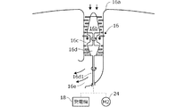
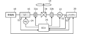
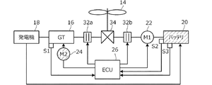
図1はこの発明の実施形態に係るハイブリッド飛行体を概略的に示す斜視図、図2は図1のハイブリッド飛行体の部分側面断面図、図3は図1のハイブリッド飛行体のガスタービン・エンジンと電動機によるパラレル駆動のときの構成要素の接続を全体的に示すブロック図である。 1 is a perspective view schematically showing a hybrid air vehicle according to an embodiment of the present invention, FIG. 2 is a partial side sectional view of the hybrid air vehicle of FIG. 1, and FIG. 3 is a gas turbine engine of the hybrid air vehicle of FIG. FIG. 3 is a block diagram generally showing the connection of components when parallel driving by an electric motor.
図1などにおいて、符号10はハイブリッド飛行体(以下「飛行体」という)を示し、飛行体10は、機体12と、機体12を推進させる推進力を生じる複数個のロータ14と、機体12に取り付けられると共に、ロータ14を駆動可能なガスタービン・エンジン(以下「GT」という)16と、GT16の出力軸に接続されて電力を発電する発電機18と、発電機18で発電された電力を蓄電するバッテリ20と、バッテリ20から電力の供給を受けてロータ14を駆動可能な電動機(図で「M1」と示す)22と、GT16の出力軸に接続されると共に、バッテリ20から電力の供給を受けてGT16を駆動可能な第2の電動機(図で「M2」と示す)24と、電動機22とGT16の少なくともいずれかによる複数個のロータ14の駆動を調整して飛行を制御する制御部(電子制御ユニットElectronic Control Unit、以下「ECU」という)26とを備えるパラレル型から構成されると共に、垂直離着陸(Vertical Take-Off and Landing)可能に構成される。機体12の底部には接地用のそり28が取り付けられる。
In FIG. 1 and the like,
機体12の内部にはGT16などが収容される。飛行体10は無人型とするが、機体12に乗員席を設けて有人型としても良い。
The GT 16 and the like are housed inside the
複数個のロータ(ファン、プロペラ)14は取り付け軸30を介して機体12に上面視において放射状に取り付けられる2n(n≦2)個、具体的には、RF(右前)の14a,RR(右後)の14b,LF(左前)の14c,LR(左後)の14dの4個から構成される。
A plurality of rotors (fans, propellers) 14 are radially attached to the
ロータ14はヨー軸(Z軸。重力軸)と平行な回転軸線を備えた、公知の形状の1枚ブレードの固定翼からなる。飛行体10においてロータ14の個数はn=2(クワッドコプタ)に限られるものではなく、n=3(ヘキサコプタ)n=4(オクタコプタ)などであっても良い。
The
4個のロータ14はそれぞれ基部に前記した電動機(M1)22を備え、電動機22で駆動されると共に、GT16でも駆動可能なように構成される。即ち、図3と図4に示す如く、GT16と電動機22とは電磁クラッチ32a,32bを介してギアボックス34に接続され、そこで電動機22とGT16の回転軸(図示せず)は4個のロータ14に入力される。
Each of the four
4個のロータ14は、例えば14a,14dからなる組はCW(時計方向)に回転すると共に、14b,14cからなる他方の組はCCW(反時計方向)に回転することで、飛行体10の姿勢を水平に維持するように構成される。図3に示すGT16と電動機22によるパラレル駆動のときはGT16と電動機22の回転の合力が4個のロータ14に伝達される一方、後述する図7に示す電動機22のみによるシリーズ駆動のときは電動機22の回転のみが4個のロータ14に伝達される。
The four
GT16は、図2に示すような公知のターボシャフト・エンジンからなり、機体12に開口された吸気口16aから吸入される吸入空気を静翼との間で圧縮するファン動翼からなる圧縮機16bと、その下流に配置される燃焼室16cと、圧縮機16bに接続されて一体に回転するタービン16dとからなる1軸構造を備える。尚、図1と図2で圧縮された吸入空気の排気口16eの機体12側の開口の図示は省略する。
The
タービン16dの出力軸(タービン出力軸、即ち、GT16の出力軸)16d1は適宜な減速機構(図示せず)を介して発電機18に接続され、発電機18を駆動する。発電機18はタービン16dの駆動によって電力(交流電力)を発電する。発電機18で発電された電力はPDU(パワードライブユニット)(図示せず)のコンバータで直流電力に変換され、バッテリ20に貯留される。
An output shaft of the
また、タービン出力軸16d1は第2の電動機24に接続され、燃料供給停止時には第2の電動機24によってGT16が回転(モータリング(空転))させられるように構成される。図示の如く、GT16の出力軸(タービン出力軸16d1)は機体12のヨー軸(Z軸)に平行な方向に取り付けられる。
Further, the turbine output shaft 16d1 is connected to the second
バッテリ20は電動機22に接続される。即ち、バッテリ20からの放電電力はPDUのインバータを介して交流に変換され、4個のロータ14にそれぞれ配置される4個の電動機22に交流電力を供給する。電動機22はブラシレスDCモータからなり、その三相コイル(図示せず)が順次通電されることで回転する。第2の電動機24も電動機22と同様、ブラシレスDCモータからなる。
The
この実施形態に係る飛行体10において、GT16は100kW、電動機22は20kW、バッテリ20は10kW程度の電力規模を備える。バッテリ20は残量SOC(State of Charge)を自己診断するBMS(Battery Management System)20a(図4に示す)を内蔵する。
In the
図5は図3などのECU(制御部)26とセンサ類に焦点をおいて示すブロック図である。 FIG. 5 is a block diagram showing the ECU (control unit) 26 and sensors shown in FIG.
ECU26は、図5に示す如く、少なくとも1個のプロセッサ(CPU)26aとROM,RAMなどの複数個のメモリ26bと、I/O26cとを備えるマイクロコンピュータからなり、容器に収容されて適宜位置に配置される。
As shown in FIG. 5, the ECU 26 is composed of a microcomputer including at least one processor (CPU) 26a, a plurality of
センサ類について説明すると、GT16のタービン出力軸16d1の付近には回転数センサ40が配置され、タービン回転数N1を示す信号を出力する。機体12に開口された吸気口16aの付近には温度センサ42が配置され、GT入口温度T1を示す信号を出力すると共に、燃焼室16cの下流の適宜位置には第2の温度センサ(エンジン温度検出手段。図3に「S1」と示す)44が配置され、エンジン温度(排ガス温度)EGTを示す信号を出力する。潤滑オイル供給系(図示せず)の適宜位置には第3の温度センサ(潤滑油温度検出手段)46が配置され、潤滑油の温度Toilを示す信号を出力する。
Explaining the sensors, a
また、ECU26を収容する容器の内部には圧力センサ50が配置されて大気圧P0を示す信号を出力すると共に、吸気口16aの付近には第2の圧力センサ52が配置されてGT入口圧力P1を示す信号を出力する。
Further, a
また、機体12の底部には高度計(ALT)54が配置されて下方にレーザビームなどを放射して得た反射波から飛行体10の高度ALT(altitude)を示す出力を生じると共に、機体12の適宜位置にはジャイロセンサ56が配置されて絶対座標軸X,Y,Z(図1に示す)のZ軸(ヨー軸)に対する機体12の傾斜を示す出力を生じる。
An altimeter (ALT) 54 is arranged at the bottom of the
また、機体12の適宜位置にはGPS受信機60が設けられて衛星群から得た受信信号に基づいて飛行体10の位置を示す出力を生じる。また、機体12の下方には第1のビジョンセンサ62が図1に示すように1個下向きに取り付けられて進行方向の撮像画像を出力すると共に、機体12の後方と側方にも第2のビジョンセンサ64が複数個取り付けられて後方または側方の撮像画像を出力する。さらに、機体12の適宜位置には方位計66が設けられて絶対方位を示す出力を生じると共に、障害物検知センサ70が設けられて進行方向に超音波信号を放射して反射波から障害物の有無を示す出力を生じる。
In addition, a
また、4個のロータ14のそれぞれに配置される電動機24の回転軸の付近には回転数センサ72が配置され、モータ回転数Nmを示す出力を生じる。また、前記したようにバッテリ20のBMS20a(蓄電量検出手段。図3に「S2」と示す)はSOCを示す出力もECUを生じると共に、バッテリ20とPDUの間には電流・電圧センサ20b(バッテリ故障検出手段。図3に「S3」と示す)が配置され、バッテリ20に入出力される電力の電流と電圧を示す出力を生じる。さらに、そり28にはWOW(Weight-on-wheel)センサ74が配置され、機体12の着地(着陸)時に着地を示す出力を生じる。
Further, a
尚、機体12の適宜位置にはメインスイッチ80が設けられ、オペレータ(ユーザ)によってメインスイッチ80がオンされてGT16が始動されると共に、バッテリ20から動作電源が供給されることによってECU26のCPU26aは動作開始する。さらに、ECU26には入力機器82とディスプレイ84が接続される。
A
上記したセンサの出力はECU26に送られる。ECU26はそれらの出力からGT16の運転状態を検出し、燃焼室16cに供給する燃料の調量によってタービン回転数を増減するなどしてGT16の運転を制御すると共に、バッテリ20の動作状態を検出し、GT16と電動機22によるロータ14の駆動を調整して飛行体10の飛行を制御する。また、ECU26はGPS受信機60の出力から経時的変化から飛行体10の飛行速度を検出する。
The output of the above-mentioned sensor is sent to the
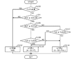
図5と図6はECU26の動作、即ち、この実施形態に係る飛行体10の動作を示すフロー・チャートである。図5は飛行体10の通常モードでの飛行についての制御を、図6はその飛行におけるバッテリ満充電モードなどでの制御を示すフロー・チャートである。
5 and 6 are flow charts showing the operation of the
最初に図5を参照して説明すると、先ず、S10(S:処理ステップ)においてオペレータが入力機器82とディスプレイ84を通じて入力(指示)した目的地、フライトコースなどのフライトミッションを読み込み、S12に進んでGT16に燃料を供給して駆動する。
First, referring to FIG. 5, first, in S10 (S: processing step), a flight mission such as a destination or a flight course input (instructed) by the operator through the
次いでS14に進み、離陸可能か否か判断し、否定されるときは以降の処理をスキップする一方、肯定されるときはS16に進み、離陸動作を行う。 Next, in S14, it is determined whether or not it is possible to take off. If the answer is negative, the subsequent processing is skipped, while if the answer is affirmative, the operation proceeds to S16 to perform a takeoff operation.
離陸動作においてはGT16の回転でロータ14を回転させると共に、4個のロータ14の回転数を均等に増加させるように制御する。
In the takeoff operation, the
次いでS18に進み、高度計54の出力に基づき、飛行体10が所定の高度に達したか、換言すれば離陸動作が完了したか否か判断し、否定されるときはS16に戻る一方、肯定されるときはS20に進み、機体12(即ち、飛行体10)の飛行動作を行う。
Next, in S18, it is determined based on the output of the
飛行動作においては、ジャイロセンサ56の出力に基づき、機体12の姿勢を微調整しつつ、入力された目的地に向けて飛行する。例えば、4個のロータ14のうち、前部の14a,14cの回転数を低下させると共に、後部の14b,14dの回転数を上昇させることで飛行方向が制御される。
In the flight operation, the attitude of the
また、旋回は、例えば右に旋回しようとするときは、4個のロータ14のうち、右側の2個14a,14bの回転数を低下させると共に、左側の2個14c,14dの回転数を上昇させ、それによって回転数が高い側のロータ14の反力で機体12を所望の方向に旋回させる。尚、旋回の度合いはロータ14の回転数の増減で調整する。
Further, for example, when trying to turn to the right, the turning decreases the rotation speed of the two
また、回転制御(ヨー軸回り回転)で、機体12をCCWに回転させるには、ロータ14のうちCW回転側のロータ14a,14dの回転数を上昇させると共に、CCW側のロータ14b,14cの回転数を下降させて行う。機体12をCWに回転させるのは上記と逆となる。
Further, in order to rotate the
次いでS22に進み、GPS受信機60の出力に基づき、目的地の上空に到達したか否か判断し、否定されるときはS20に戻る一方、肯定されるときはS24に進み、機体12(飛行体10)の着陸動作に移行する。
Next, in S22, it is determined based on the output of the
機体12の着陸動作は、4個のロータ14の全ての回転数を徐々に低下させることで行う。この処理はS26でWOWセンサ74の出力から着地と判断されるまで行う。
The landing operation of the
図6は図5の処理と平行してECU26によって行われる、バッテリ満充電モードなどでの制御を示すフロー・チャートである。
FIG. 6 is a flow chart showing control in the battery full charge mode or the like performed by the
以下説明すると、S100においてバッテリ20が故障したか否か判断する。バッテリ20の故障はバッテリ20の電流・電圧を検出するセンサ20bの出力が所定時間に亘って変化しない場合などから判断する。S100で肯定されるときはS102に進み、GT16の駆動を継続する。即ち、バッテリ20が故障したとしても、飛行運航の安全性を高めるためにGT16の駆動を継続する。
Explaining below, it is determined in S100 whether the
他方、S100で否定されるときはS104に進み、BMS20aから検出されるバッテリ20の残量SOCが所定値SOCref以上か否か判断する。所定値は例えばバッテリ20の満充電相当値またはその近傍の値とする。
On the other hand, when the result in S100 is NO, the program proceeds to S104, in which it is determined whether or not the SOC of the
S104で否定されるときはS102に進む一方、肯定されるときはS106に進み、第2の温度センサ44の出力に基づいてGT16のエンジン温度EGTが所定温度EGTref以上か否か判断する。
When the result in S104 is negative, the process proceeds to S102, while when the result is affirmative, the process proceeds to S106, in which it is determined based on the output of the
S106で肯定されるときはS108に進み、第3の温度センサ46の出力に基づいてGT16の潤滑油の温度Toilが第1の規定温度Toilref1以下か否か判断し、肯定されるときはS110に進み、GT16の駆動を停止すると共に、第2の電動機24を駆動してGT16をモータリングする(空転させる)。
When the result in S106 is affirmative, the routine proceeds to S108, in which it is determined based on the output of the
一方、S106で否定されるときはS112に進み、GT16の潤滑油の温度Toilが第2の規定温度Toilref2以下か否か判断し、肯定されるときはS110に進んでGT16をモータリングする。 On the other hand, when the result in S106 is negative, the program proceeds to S112, in which it is determined whether the temperature Toil of the lubricating oil in the GT16 is equal to or lower than the second specified temperature Toilref2.
他方、S112で否定されるときはS114に進み、GT16を停止する(ただしモータリングは行わない)。即ち、S104でバッテリ20が満充電と判断される一方、S106でエンジン温度も所定温度未満と判断されることから、GT16を停止して電動機22の出力のみでロータ14を駆動する。
On the other hand, when the result in S112 is NO, the program proceeds to S114, in which the
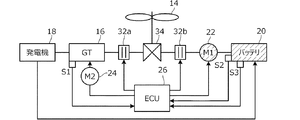
図3は前記したGT16と電動機22によるパラレル駆動のときの、図7はバッテリ満充電時の電動機22のみによるシリーズ駆動(S114)のときの、図8はGT16停止後の第2の電動機24によるGT16のモータリング(S110)のときの処理を示すブロック図である。尚、図3などにおいてハッチングはバッテリ20についてはSOCの程度を示し、その他の要素については動作していることを示す。
3 shows the above-described parallel driving by the
上記した如く、S104でバッテリ20の残量SOCが所定値SOCref未満と判断されるときは、図3に示す如く、GT16の駆動を継続すると共に、電動機22の駆動も継続する(S102)。従って、ロータ14はGT16と電動機22で駆動される。これはS100でバッテリ20の故障が検出されたときも同様である。
As described above, when the remaining amount SOC of the
他方、S104でバッテリ20の残量SOCが所定値SOCref以上で、かつS106でGT16の排ガス温度EGTが所定温度EGTref未満と判断されるときは、図7に示す如く、GT16の駆動を停止する(S114)。従ってロータ14は電動機22で駆動される。この場合はGT16のモータリングは行われない。GT16の潤滑油の温度Toilが第1の規定温度Toilref1を超えるときも同様である。
On the other hand, when the remaining amount SOC of the
一方、バッテリ20の残量SOCが所定値SOCref以上で、かつGT16のエンジン温度EGTが所定温度EGTref以上のときは、図8に示すごとく、GT16を停止すると共に、第2の電動機24を駆動してGT16をモータリングする(S110)。GT16の潤滑油の温度Toilが第1の規定温度Toilref1以下のときも同様である。
On the other hand, when the SOC of the
また、バッテリ20の残量SOCが所定値SOCref以上であるが、GT16のエンジン温度EGTが所定温度EGTref未満のときも、GT16を停止すると共に、第2の電動機24を駆動してGT16をモータリングする(S110)。
When the SOC of the
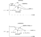
図9はこの実施形態の効果を示すタイム・チャートである。 FIG. 9 is a time chart showing the effect of this embodiment.
同図(i)に示す如く、従来技術においては、GT16を停止した直後に何等かの理由で緊急再始動した場合、エンジン温度EGTが上昇して、燃焼室16cの出口部の静翼や動翼などの耐久性を低下させる惧れがある。GT16を長時間停止すると、冬季などにあって着氷や潤滑油温度の低下によって潤滑油の粘性が低下してエンジン始動性能の低下を招く惧れがある。
As shown in (i) of the figure, in the conventional technique, when the
しかしながら、この実施形態においては上記の如く構成したので、GT16を停止した直後に緊急再始動しても、GT16を停止している間に第2の電動機24でGT16をモータリングすることから、吸気口16aからの空気の吸入が継続されるためにエンジン温度EGTの低下が促進され、よって(ii)に示すように過温度となることがない。
However, in this embodiment, since the configuration is as described above, even if the
また、GT16の停止判断においても、GT16の潤滑油の温度Toilが第1、第2の規定温度Toilref1,Toilref2以下のときは、GT16を停止している間に第2の電動機24でGT16をモータリングすることから、燃焼室16cで燃焼は行われないものの、圧縮機16b(とタービン16d)は駆動されて潤滑油も流入・流出されるので、潤滑油の粘性が低下してGT16の始動が困難になることがない。
Even when the
この実施形態にあっては、機体12と、前記機体を推進させる推進力を生じる複数個のロータ14と、前記機体に取り付けられると共に、前記複数個のロータを駆動可能なガスタービン・エンジン(GT)16と、前記ガスタービン・エンジンの出力軸(タービン出力軸16d1)に接続されて電力を発電する発電機18と、前記発電機で発電された電力を蓄電するバッテリ20と、前記バッテリから電力の供給を受けて前記複数個のロータを駆動可能な電動機(M1)22と、前記ガスタービン・エンジンの出力軸に接続されると共に、前記バッテリから電力の供給を受けて前記ガスタービン・エンジンを駆動可能な第2の電動機(M2)24と、少なくとも前記ガスタービン・エンジンの温度を検出するエンジン温度検出手段(第2の温度センサ44,S1)と、前記バッテリ20の蓄電量を検出する蓄電量検出手段(BMS20a,S2)と、前記電動機と前記ガスタービン・エンジンの少なくともいずれかによる複数個のロータの駆動を調整して飛行を制御する制御部(ECU)26とを備えた垂直離着陸可能なハイブリッド飛行体10において、前記制御部は、前記蓄電量検出手段によって検出されたバッテリ20の蓄電量が所定値以上のとき、前記ガスタービン・エンジン16への燃料供給を停止すると共に(S104,S114,S110)、前記温度検出手段によって検出されたガスタービン・エンジン16の温度が所定温度以上のとき、前記バッテリ20から前記第2の電動機24に電力を供給して前記第2の電動機で前記ガスタービン・エンジン16をモータリングする(S106,S110)如く構成したので、GT16を停止した直後に緊急再始動しても、GT16を停止している間に第2の電動機24でGT16をモータリングすることから、吸気口16aからの空気の吸入が継続されるためにエンジン温度EGTの低下が促進され、過温度となることがない。
In this embodiment, the
また、前記バッテリ20の故障を検出するバッテリ故障検出手段(電流・電圧センサ22b,S3)を備えると共に、前記制御部26は、前記バッテリ20の故障が検出されたとき、前記ガスタービン・エンジンへの燃料供給を継続する(S100,S102)如く構成したので、上記した効果に加え、飛行体10の飛行運航の安全性を高めることができる。
Further, a battery failure detecting means (current / voltage sensor 22b, S3) for detecting a failure of the
また、前記ガスタービン・エンジン16の潤滑油の温度を検出する潤滑油温度検出手段(第3の温度センサ46)を備えると共に、前記制御部26は、前記潤滑油温度検出手段によって検出された前記ガスタービン・エンジンの潤滑油の温度が規定温度以下のとき、前記バッテリ20から前記第2の電動機24に電力を供給して前記第2の電動機24で前記ガスタービン・エンジン16をモータリングする(S108,S112,S110)如く構成したので、GT16を停止している間に第2の電動機24でGT16をモータリングすることで、燃焼室16cで燃焼は行われないものの、圧縮機16b(とタービン16d)は駆動されて潤滑油も流入・流出されるので、潤滑油の粘性が低下してGT16の再始動時の始動が困難になることがない。
Further, the
尚、上記において発電機18と電動機22と第2の電動機24は、発電機としても電動機としても動作可能な発電電動機(モータジェネレータ)であっても良い。
In the above, the
10 ハイブリッド飛行体(飛行体)、12 機体、14,14a,14b,14c,14d ロータ、16 ガスタービン・エンジン(GT)、16a 吸気口、16b 圧縮機、16c 燃焼室、16d タービン、16d1 タービン出力軸(出力軸)、18 発電機、20 バッテリ、20a BMS(蓄電量検出手段、S2)、20b 電流・電圧センサ(バッテリ故障検出手段、S3)、22 電動機(M1)、24 第2の電動機(M2)、26 電子制御ユニット(ECU。制御部)、28 そり、30 取り付け軸、40 回転数センサ、44 第2の温度センサ(エンジン温度検出手段、S1)、46 第3の温度センサ(潤滑油温度検出手段)、50,52 圧力センサ、54 高度計(ALT)、56 ジャイロセンサ、60 GPS受信機、62,64 ビジョンセンサ、70 障害物検知センサ、72 回転数センサ、80 メインスイッチ、82 入力機器、84 ディスプレイ
10 hybrid aircraft (aircraft), 12 aircraft, 14, 14a, 14b, 14c, 14d rotor, 16 gas turbine engine (GT), 16a intake port, 16b compressor, 16c combustion chamber, 16d turbine, 16d1 turbine output Shaft (output shaft), 18 generator, 20 battery, 20a BMS (storage amount detecting means, S2), 20b current / voltage sensor (battery failure detecting means, S3), 22 electric motor (M1), 24 second electric motor ( M2), 26 electronic control unit (ECU. Control unit), 28 sled, 30 mounting shaft, 40 rotation speed sensor, 44 second temperature sensor (engine temperature detecting means, S1), 46 third temperature sensor (lubricating oil) Temperature detecting means), 50,52 pressure sensor, 54 altimeter (ALT), 56 gyro sensor, 60 GPS receiver, 62,6 4 Vision Sensor, 70 Obstacle Detection Sensor, 72 Rotation Speed Sensor, 80 Main Switch, 82 Input Equipment, 84 Display
Claims (3)
The control unit includes a lubricating oil temperature detecting unit that detects the temperature of the lubricating oil of the gas turbine engine, and the control unit sets the temperature of the lubricating oil of the gas turbine engine detected by the lubricating oil temperature detecting unit to a specified temperature. The hybrid flight according to claim 1 or 2, wherein electric power is supplied from the battery to the second electric motor to motor the gas turbine engine with the second electric motor when: body.
Priority Applications (3)
| Application Number | Priority Date | Filing Date | Title |
|---|---|---|---|
| JP2018206994A JP7057264B2 (en) | 2018-11-02 | 2018-11-02 | Hybrid flying object |
| US16/660,552 US11939068B2 (en) | 2018-11-02 | 2019-10-22 | Hybrid flight vehicle |
| CN201911047281.5A CN111137460B (en) | 2018-11-02 | 2019-10-30 | Hybrid aircraft |
Applications Claiming Priority (1)
| Application Number | Priority Date | Filing Date | Title |
|---|---|---|---|
| JP2018206994A JP7057264B2 (en) | 2018-11-02 | 2018-11-02 | Hybrid flying object |
Publications (2)
| Publication Number | Publication Date |
|---|---|
| JP2020069975A true JP2020069975A (en) | 2020-05-07 |
| JP7057264B2 JP7057264B2 (en) | 2022-04-19 |
Family
ID=70516917
Family Applications (1)
| Application Number | Title | Priority Date | Filing Date |
|---|---|---|---|
| JP2018206994A Active JP7057264B2 (en) | 2018-11-02 | 2018-11-02 | Hybrid flying object |
Country Status (3)
| Country | Link |
|---|---|
| US (1) | US11939068B2 (en) |
| JP (1) | JP7057264B2 (en) |
| CN (1) | CN111137460B (en) |
Cited By (2)
| Publication number | Priority date | Publication date | Assignee | Title |
|---|---|---|---|---|
| JP2022099065A (en) * | 2020-12-22 | 2022-07-04 | 本田技研工業株式会社 | Aircraft propulsion system |
| JP2022099063A (en) * | 2020-12-22 | 2022-07-04 | 本田技研工業株式会社 | Propulsion system for aircraft |
Families Citing this family (8)
| Publication number | Priority date | Publication date | Assignee | Title |
|---|---|---|---|---|
| US10906637B2 (en) * | 2018-05-17 | 2021-02-02 | Textron Innovations Inc. | Assisted landing systems for rotorcraft |
| JP7021054B2 (en) * | 2018-11-08 | 2022-02-16 | 本田技研工業株式会社 | Hybrid flying object |
| JP7049234B2 (en) * | 2018-11-15 | 2022-04-06 | 本田技研工業株式会社 | Hybrid flying object |
| KR102212086B1 (en) * | 2020-09-08 | 2021-02-05 | 유한회사 우주무인항공산업 | Drone with self-powered function |
| JP7430134B2 (en) * | 2020-12-22 | 2024-02-09 | 本田技研工業株式会社 | Aircraft propulsion system |
| US11661185B2 (en) * | 2021-02-12 | 2023-05-30 | Textron Innovations Inc. | Redundant electric propulsion system |
| CN114233651A (en) * | 2021-12-20 | 2022-03-25 | 中国科学院工程热物理研究所 | Axial flow compression expansion type energy conversion device and control method |
| CN118163973B (en) * | 2024-05-16 | 2024-08-27 | 长春长光博翔无人机有限公司 | Distributed multi-source hybrid unmanned aerial vehicle and power system control method |
Citations (4)
| Publication number | Priority date | Publication date | Assignee | Title |
|---|---|---|---|---|
| JP2010101210A (en) * | 2008-10-22 | 2010-05-06 | Toyota Motor Corp | Starting device for internal combustion engine |
| US20100300117A1 (en) * | 2005-05-19 | 2010-12-02 | Djamal Moulebhar | Aircraft with disengageable auxiliary power unit components |
| JP2016088111A (en) * | 2014-10-29 | 2016-05-23 | ヤンマー株式会社 | helicopter |
| US20170320584A1 (en) * | 2016-05-05 | 2017-11-09 | Pratt & Whitney Canada Corp. | Hybrid gas-electric turbine engine |
Family Cites Families (16)
| Publication number | Priority date | Publication date | Assignee | Title |
|---|---|---|---|---|
| JP3700776B2 (en) * | 2001-12-07 | 2005-09-28 | アイシン・エィ・ダブリュ株式会社 | Vehicle drive control device |
| JP3574121B2 (en) * | 2002-08-07 | 2004-10-06 | 本田技研工業株式会社 | Engine stop / start control device for hybrid vehicle |
| JP4064428B2 (en) * | 2006-05-24 | 2008-03-19 | 本田技研工業株式会社 | Control device for internal combustion engine |
| US20080184906A1 (en) * | 2007-02-07 | 2008-08-07 | Kejha Joseph B | Long range hybrid electric airplane |
| US8727271B2 (en) * | 2008-01-11 | 2014-05-20 | Ival O. Salyer | Aircraft using turbo-electric hybrid propulsion system |
| US8128019B2 (en) * | 2008-12-12 | 2012-03-06 | Honeywell International Inc. | Hybrid power for ducted fan unmanned aerial systems |
| DE102010021026A1 (en) * | 2010-05-19 | 2011-11-24 | Eads Deutschland Gmbh | Hybrid propulsion and power system for aircraft |
| US9890754B2 (en) * | 2013-09-02 | 2018-02-13 | Toyota Jidosha Kabushiki Kaisha | Control apparatus for a vehicle |
| JP2015137092A (en) * | 2014-01-20 | 2015-07-30 | 憲太 安田 | Parallel hybrid multi-rotor aircraft |
| CN106285938A (en) * | 2015-06-05 | 2017-01-04 | 姜志凌 | A kind of capacity degree of depth hybrid engine done work that heats up of independently calming the anger |
| EP3124379B1 (en) * | 2015-07-29 | 2019-05-01 | Airbus Defence and Space GmbH | Hybrid-electric drive train for vtol drones |
| CN105539828B (en) * | 2015-12-08 | 2024-05-31 | 湖南众盛机械设备有限公司 | Self-generating oil-electricity hybrid power multi-rotor aircraft |
| CN105909377B (en) * | 2016-05-06 | 2018-10-23 | 王领军 | A kind of coaxial oil electric mixed dynamic engine |
| CN206125418U (en) * | 2016-11-07 | 2017-04-26 | 南昌航空大学 | Hybrid aircraft |
| CN107628241A (en) * | 2017-09-25 | 2018-01-26 | 安徽瓦尔特机械贸易有限公司 | A kind of unmanned plane hybrid power system |
| CN108082500A (en) * | 2018-01-29 | 2018-05-29 | 吉林大学 | A kind of fixed-wing formula hybrid power aircraft driving device and driving method |
-
2018
- 2018-11-02 JP JP2018206994A patent/JP7057264B2/en active Active
-
2019
- 2019-10-22 US US16/660,552 patent/US11939068B2/en active Active
- 2019-10-30 CN CN201911047281.5A patent/CN111137460B/en active Active
Patent Citations (4)
| Publication number | Priority date | Publication date | Assignee | Title |
|---|---|---|---|---|
| US20100300117A1 (en) * | 2005-05-19 | 2010-12-02 | Djamal Moulebhar | Aircraft with disengageable auxiliary power unit components |
| JP2010101210A (en) * | 2008-10-22 | 2010-05-06 | Toyota Motor Corp | Starting device for internal combustion engine |
| JP2016088111A (en) * | 2014-10-29 | 2016-05-23 | ヤンマー株式会社 | helicopter |
| US20170320584A1 (en) * | 2016-05-05 | 2017-11-09 | Pratt & Whitney Canada Corp. | Hybrid gas-electric turbine engine |
Cited By (3)
| Publication number | Priority date | Publication date | Assignee | Title |
|---|---|---|---|---|
| JP2022099065A (en) * | 2020-12-22 | 2022-07-04 | 本田技研工業株式会社 | Aircraft propulsion system |
| JP2022099063A (en) * | 2020-12-22 | 2022-07-04 | 本田技研工業株式会社 | Propulsion system for aircraft |
| JP7355726B2 (en) | 2020-12-22 | 2023-10-03 | 本田技研工業株式会社 | Aircraft propulsion system |
Also Published As
| Publication number | Publication date |
|---|---|
| CN111137460B (en) | 2023-07-07 |
| US11939068B2 (en) | 2024-03-26 |
| CN111137460A (en) | 2020-05-12 |
| US20200148376A1 (en) | 2020-05-14 |
| JP7057264B2 (en) | 2022-04-19 |
Similar Documents
| Publication | Publication Date | Title |
|---|---|---|
| JP7057264B2 (en) | Hybrid flying object | |
| CN109421924B (en) | Multi-rotor helicopter | |
| JP6879866B2 (en) | Vertical takeoff and landing aircraft | |
| CN111186584B (en) | Hybrid aircraft | |
| CN111152929B (en) | Hybrid aircraft | |
| CN108945479B (en) | Hybrid electric propulsion system for aircraft and method of operating the same | |
| US9446842B2 (en) | Hybrid power rotary wing aircraft | |
| US20210237887A1 (en) | Propulsion system for a helicopter | |
| US11465518B2 (en) | Charging scheme for electric propulsion systems | |
| CN114715391A (en) | Propulsion system for aircraft | |
| JP7542461B2 (en) | Aircraft Propulsion Systems | |
| EP4019406B1 (en) | Multicopter with propulsion system | |
| JP2021090315A (en) | Engine driven power generator | |
| US20230278713A1 (en) | Power unit control system, power unit control method, and power unit control program | |
| US20230234717A1 (en) | Aircraft control system, aircraft control method, and storage medium | |
| US20220194577A1 (en) | Aircraft propulsion system |
Legal Events
| Date | Code | Title | Description |
|---|---|---|---|
| A621 | Written request for application examination |
Free format text: JAPANESE INTERMEDIATE CODE: A621 Effective date: 20201130 |
|
| A977 | Report on retrieval |
Free format text: JAPANESE INTERMEDIATE CODE: A971007 Effective date: 20211014 |
|
| A131 | Notification of reasons for refusal |
Free format text: JAPANESE INTERMEDIATE CODE: A131 Effective date: 20211109 |
|
| A521 | Request for written amendment filed |
Free format text: JAPANESE INTERMEDIATE CODE: A523 Effective date: 20211215 |
|
| A131 | Notification of reasons for refusal |
Free format text: JAPANESE INTERMEDIATE CODE: A131 Effective date: 20220111 |
|
| A521 | Request for written amendment filed |
Free format text: JAPANESE INTERMEDIATE CODE: A523 Effective date: 20220113 |
|
| TRDD | Decision of grant or rejection written | ||
| A01 | Written decision to grant a patent or to grant a registration (utility model) |
Free format text: JAPANESE INTERMEDIATE CODE: A01 Effective date: 20220405 |
|
| A61 | First payment of annual fees (during grant procedure) |
Free format text: JAPANESE INTERMEDIATE CODE: A61 Effective date: 20220407 |
|
| R150 | Certificate of patent or registration of utility model |
Ref document number: 7057264 Country of ref document: JP Free format text: JAPANESE INTERMEDIATE CODE: R150 |