JP2020064183A - Keyboard instrument - Google Patents

Keyboard instrument Download PDF

Info

Publication number
JP2020064183A
JP2020064183A JP2018195935A JP2018195935A JP2020064183A JP 2020064183 A JP2020064183 A JP 2020064183A JP 2018195935 A JP2018195935 A JP 2018195935A JP 2018195935 A JP2018195935 A JP 2018195935A JP 2020064183 A JP2020064183 A JP 2020064183A
Authority
JP
Japan
Prior art keywords
key
hammer
keyboard
groove
cap
Prior art date
Legal status (The legal status is an assumption and is not a legal conclusion. Google has not performed a legal analysis and makes no representation as to the accuracy of the status listed.)
Granted
Application number
JP2018195935A
Other languages
Japanese (ja)
Other versions
JP7280548B2 (en
Inventor
暁久 星野
Akihisa Hoshino
暁久 星野
弘和 谷口
Hirokazu Taniguchi
弘和 谷口
Current Assignee (The listed assignees may be inaccurate. Google has not performed a legal analysis and makes no representation or warranty as to the accuracy of the list.)
Casio Computer Co Ltd
Original Assignee
Casio Computer Co Ltd
Priority date (The priority date is an assumption and is not a legal conclusion. Google has not performed a legal analysis and makes no representation as to the accuracy of the date listed.)
Filing date
Publication date
Application filed by Casio Computer Co Ltd filed Critical Casio Computer Co Ltd
Priority to JP2018195935A priority Critical patent/JP7280548B2/en
Priority to CN201910878693.7A priority patent/CN111063321B/en
Publication of JP2020064183A publication Critical patent/JP2020064183A/en
Priority to JP2023077632A priority patent/JP2023090912A/en
Application granted granted Critical
Publication of JP7280548B2 publication Critical patent/JP7280548B2/en
Active legal-status Critical Current
Anticipated expiration legal-status Critical

Links

Images

Classifications

    • GPHYSICS
    • G10MUSICAL INSTRUMENTS; ACOUSTICS
    • G10CPIANOS, HARPSICHORDS, SPINETS OR SIMILAR STRINGED MUSICAL INSTRUMENTS WITH ONE OR MORE KEYBOARDS
    • G10C3/00Details or accessories
    • G10C3/12Keyboards; Keys
    • GPHYSICS
    • G10MUSICAL INSTRUMENTS; ACOUSTICS
    • G10HELECTROPHONIC MUSICAL INSTRUMENTS; INSTRUMENTS IN WHICH THE TONES ARE GENERATED BY ELECTROMECHANICAL MEANS OR ELECTRONIC GENERATORS, OR IN WHICH THE TONES ARE SYNTHESISED FROM A DATA STORE
    • G10H1/00Details of electrophonic musical instruments
    • G10H1/32Constructional details
    • G10H1/34Switch arrangements, e.g. keyboards or mechanical switches specially adapted for electrophonic musical instruments

Abstract

To provide a keyboard instrument on which a stable keying operation can be performed.SOLUTION: A hammer cap 51 of a hammer member 40 engaged with through holes of hammer coupling parts 24, 34 of a key has a wide end-side projection part 55 protruding toward both ends through a groove part 54 provided on a top surface 53. A clearance between the end-side projection part 55 of the hammer cap 51 and sideward inner walls 24b, 34b of the through holes of the hammer coupling parts 24, 34 is set to be small. Consequently, a top surface part of the end-side projection part 55 comes into contact with upper inner walls 24a, 34a of the through holes of the hammer coupling parts 24, 34 in a wide area in a keying operation and also slides along a curved surface of the top surface 53. The end-side projection part 55 also slides relative to one of opposed sideward inner walls 24b, 34b of the through holes of the hammer coupling parts 24, 34.SELECTED DRAWING: Figure 11

Description

この発明は、電子ピアノ等の鍵盤装置を備えた鍵盤楽器に関する。   The present invention relates to a keyboard instrument equipped with a keyboard device such as an electronic piano.

従来、電子ピアノ等の電子鍵盤楽器においては、アコースティックピアノと同様の鍵盤の操作感を実現するため、例えば特許文献1に記載されているような鍵盤装置が知られている。この鍵盤装置においては、鍵盤シャーシ上に上下方向に回動可能に支持された鍵(白鍵、黒鍵)と、鍵への押鍵操作に連動して回動し、鍵にアクション荷重を付与するハンマー部材とを有し、鍵とハンマー部材との連結部において、鍵側に設けられた突起部がハンマー部材側に取り付けられた連結部材(又は受け部材)の凹部底面に摺接して移動する構造を有している。ここで、連結部材(又は受け部材)は、連結部における摺接に起因する摩耗やノイズの発生を抑制するために、可撓性材料が用いられている。   2. Description of the Related Art Conventionally, in an electronic keyboard instrument such as an electronic piano, a keyboard device as described in, for example, Patent Document 1 is known in order to realize a keyboard operation feeling similar to that of an acoustic piano. In this keyboard device, the keys (white keys and black keys) supported on the keyboard chassis so as to be rotatable in the vertical direction, and the keys are rotated in conjunction with the key pressing operation, and an action load is applied to the keys. In the connecting portion between the key and the hammer member, the protrusion provided on the key side slides on the bottom surface of the recess of the connecting member (or the receiving member) attached to the hammer member to move. It has a structure. Here, a flexible material is used for the connecting member (or the receiving member) in order to suppress the generation of wear and noise due to the sliding contact at the connecting portion.

特開2012−145728号公報JP 2012-145728 A

上述したような構造を有する鍵盤装置においては、鍵側の突起部の先端のみがハンマー部材側の連結部材の一面(凹部底面)に常時摺接して移動するため、可撓性を有する連結部材が摩擦により摩耗したり、押鍵時の強い衝撃により変形や脱落したりして、ハンマー部材が正常に回動せず、押鍵時の異常な振動や異音の発生等の不具合の原因になる場合があった。   In the keyboard device having the above-described structure, since only the tip of the key-side protrusion always slides in contact with one surface (bottom surface of the recess) of the hammer member-side connecting member, a flexible connecting member is provided. It may be worn due to friction, or may be deformed or fallen off due to a strong impact when the keys are pressed, causing the hammer member to not rotate normally and causing abnormal vibrations or abnormal noises when the keys are pressed. There were cases.

そこで、本発明は、押鍵時の不具合の発生を抑制して安定した押鍵操作を行うことができる鍵盤楽器を提供することを目的とする。   Therefore, it is an object of the present invention to provide a keyboard instrument capable of performing stable key-pressing operations while suppressing the occurrence of problems when keys are pressed.

本発明に係る鍵盤楽器は、
鍵ごとに、一端側に、前記鍵に接触することによって押鍵時に押し下げられる接触部材を有する力点部が設けられ、他端側に、前記押鍵される前記鍵に対して荷重を加える錘部が設けられているハンマー部材を備え、
前記接触部材は、前記押鍵時に前記鍵に接触することがないように上面に前記鍵の長手方向に沿って設けられている溝部と、前記鍵の配列方向における前記溝部の両端側に、前記押鍵時に前記鍵に接触するように前記溝部より上方に突出している両端部と、を有していることを特徴とする。
The keyboard instrument according to the present invention,
For each key, a force point portion having a contact member that is pressed down when touching the key is provided on one end side, and a weight portion that applies a load to the key pressed on the other end side. Equipped with a hammer member,
The contact member includes a groove portion provided along the longitudinal direction of the key on the upper surface so as not to come into contact with the key at the time of pressing the key, and the both end sides of the groove portion in the arrangement direction of the key. And both end portions projecting upward from the groove portion so as to come into contact with the key when the key is pressed.

この発明によれば、安定した押鍵操作を行うことができる。   According to the present invention, a stable key depression operation can be performed.

本発明に係る鍵盤楽器の第1の実施形態を示す外観図である。1 is an external view showing a first embodiment of a keyboard musical instrument according to the present invention. 第1の実施形態に係る鍵盤楽器に適用される鍵盤ユニットの一例を示す概略図である。It is a schematic diagram showing an example of a keyboard unit applied to a keyboard musical instrument concerning a 1st embodiment. 第1の実施形態に係る鍵盤楽器に適用される白鍵の鍵盤機構を示す概略断面図である。It is a schematic sectional drawing which shows the keyboard mechanism of the white key applied to the keyboard musical instrument which concerns on 1st Embodiment. 第1の実施形態に係る鍵盤楽器に適用される黒鍵の鍵盤機構を示す概略断面図である。It is a schematic sectional drawing which shows the keyboard mechanism of the black key applied to the keyboard musical instrument which concerns on 1st Embodiment. 第1の実施形態に係る鍵盤楽器に適用される白鍵を示す概略図である。It is a schematic diagram showing a white key applied to a keyboard musical instrument concerning a 1st embodiment. 第1の実施形態に係る鍵盤楽器に適用される黒鍵を示す概略図である。It is a schematic diagram showing a black key applied to a keyboard musical instrument concerning a 1st embodiment. 第1の実施形態に係る鍵盤楽器に適用されるハンマーユニットを示す概略図である。It is a schematic diagram showing a hammer unit applied to a keyboard musical instrument concerning a 1st embodiment. 第1の実施形態に係る鍵盤楽器に適用されるハンマー部材を示す概略図である。It is a schematic diagram showing a hammer member applied to a keyboard musical instrument concerning a 1st embodiment. 第1の実施形態に係る鍵盤楽器に適用される白鍵用のハンマーキャップを示す概略図である。It is a schematic diagram showing a hammer cap for white keys applied to a keyboard musical instrument concerning a 1st embodiment. 第1の実施形態に係る鍵盤楽器に適用される黒鍵用のハンマーキャップを示す概略図である。It is a schematic diagram showing a hammer cap for black keys applied to a keyboard musical instrument concerning a 1st embodiment. 第1の実施形態に係る鍵盤楽器に適用されるハンマー部材と鍵との連結構造を示す概略図である。It is a schematic diagram showing a connecting structure of a hammer member and a key applied to a keyboard musical instrument concerning a 1st embodiment. 第2の実施形態に係る鍵盤楽器に適用されるハンマーキャップを示す概略図である。It is a schematic diagram showing a hammer cap applied to a keyboard instrument concerning a 2nd embodiment. 第2の実施形態に係る鍵盤楽器に適用される白鍵の鍵盤機構を示す概略断面図である。It is a schematic sectional drawing which shows the keyboard mechanism of the white key applied to the keyboard musical instrument which concerns on 2nd Embodiment. 第2の実施形態に係る鍵盤楽器に適用される黒鍵の鍵盤機構を示す概略断面図である。It is a schematic sectional drawing which shows the keyboard mechanism of the black key applied to the keyboard musical instrument which concerns on 2nd Embodiment. 第2の実施形態に係る鍵盤楽器に適用されるハンマー部材と鍵との連結状態を示す概略図である。It is a schematic diagram showing a state where a hammer member and a key applied to a keyboard instrument concerning a 2nd embodiment are connected.

以下、本発明を実施するための形態について、図面を参照しながら詳しく説明する。
<第1の実施形態>
(鍵盤楽器)
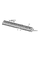
図1は、本発明に係る鍵盤楽器の第1の実施形態を示す外観図である。また、図2は、本実施形態に係る鍵盤楽器に適用される鍵盤ユニットの一例を示す概略図である。ここでは、鍵盤楽器の一例として電子ピアノを示して説明するが、ユーザ(演奏者)の押鍵操作に応じて楽音を発音するものであれば他の電子鍵盤楽器であってもよい。
Hereinafter, modes for carrying out the present invention will be described in detail with reference to the drawings.
<First Embodiment>
(Keyboard instrument)
FIG. 1 is an external view showing a first embodiment of a keyboard musical instrument according to the present invention. FIG. 2 is a schematic diagram showing an example of a keyboard unit applied to the keyboard musical instrument according to this embodiment. Here, an electronic piano is shown as an example of the keyboard instrument, but any other electronic keyboard instrument may be used as long as it produces a musical sound in response to a user (player) pressing a key.

本発明に係る鍵盤楽器100の外観は、例えば図1に示すように、楽器本体102に対してユーザ側となる一面側(図面手前側)の上部に、演奏操作子としての複数の鍵を有し、音高を指定するための鍵盤ユニット104と、鍵盤ユニット104の後方側(図面奥側)にあって、図示を省略したスピーカ等が収納される楽器本体102の上面を覆う天板106と、天板106に付設された譜面台108と、ユーザの足下となる楽器本体102の下部に、主に押鍵時の音の響きを調整するためのピアノペダル110と、を備えている。なお、図示を省略したが、鍵盤楽器100は、鍵盤ユニット104の周辺に、音量調整や音色選択等の操作を行うためのスイッチ類や、演奏中の楽曲に関する情報や各種の設定情報等を表示するための表示パネル等が配置されているものであってもよい。   The appearance of the keyboard instrument 100 according to the present invention has, as shown in FIG. 1, for example, a plurality of keys as performance operators on the upper side of one side (front side of the drawing) which is the user side with respect to the musical instrument body 102. Then, a keyboard unit 104 for designating a pitch, and a top plate 106 behind the keyboard unit 104 (back side in the drawing) that covers the upper surface of the musical instrument body 102 in which a speaker and the like (not shown) are housed. A music stand 108 attached to the top plate 106 and a piano pedal 110 mainly for adjusting the sound of a key when the key is pressed are provided below the musical instrument body 102, which is the foot of the user. Although not shown, the keyboard instrument 100 displays switches around the keyboard unit 104 for performing operations such as volume adjustment and tone color selection, information regarding the music being played, and various setting information. A display panel or the like for doing so may be arranged.

鍵盤ユニット104は、図1、図2に示すように、鍵盤楽器100の左右方向(図面左右方向;鍵の配列方向)に複数の白鍵20及び黒鍵30が所定の順序で規則的に配列されている。ここでは、鍵盤ユニット104は、合計88個の白鍵20及び黒鍵30が配列されている。鍵盤ユニット104の後方側(図面奥側)は、楽器本体102の内部に収納され、楽器本体102から露出した前方側(図面手前側)の領域がユーザによる押鍵操作が行われる領域となる。なお、本願明細書においては、「鍵」と記載した場合には、特に言及しない限り白鍵及び黒鍵に共通する事項を指す。また、以降の説明では白鍵について詳しく説明し、黒鍵について白鍵と同等又は同一の構成や動作を有する場合にはその説明を簡略化又は省略する。   As shown in FIGS. 1 and 2, the keyboard unit 104 has a plurality of white keys 20 and black keys 30 arranged regularly in a predetermined order in the left-right direction of the keyboard instrument 100 (left-right direction in the drawing; key arrangement direction). Has been done. Here, in the keyboard unit 104, a total of 88 white keys 20 and black keys 30 are arranged. A rear side (back side in the drawing) of the keyboard unit 104 is housed inside the musical instrument body 102, and a front side (front side in the drawing) area exposed from the musical instrument body 102 is an area where a user performs a key depression operation. In the specification of the application, the term "key" refers to a matter common to the white key and the black key unless otherwise specified. Further, in the following description, the white key will be described in detail, and when the black key has the same or the same configuration or operation as the white key, the description thereof will be simplified or omitted.

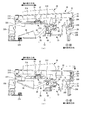
図3は、本実施形態に係る鍵盤楽器に適用される白鍵の鍵盤機構を示す概略断面図であり、図4は、本実施形態に係る鍵盤楽器に適用される黒鍵の鍵盤機構を示す概略断面図である。ここで、図3(a)、図4(a)は、押鍵操作を行っていない初期状態を示す図であり、図3(b)、図4(b)は、押鍵操作を行っている状態を示す図である。   FIG. 3 is a schematic cross-sectional view showing a white key keyboard mechanism applied to the keyboard instrument according to the present embodiment, and FIG. 4 shows a black key keyboard mechanism applied to the keyboard instrument according to the present embodiment. It is a schematic sectional drawing. Here, FIGS. 3A and 4A are diagrams showing an initial state in which a key depression operation is not performed, and FIGS. 3B and 4B show a key depression operation performed. It is a figure showing the state where it is.

鍵盤ユニット104の白鍵20は、例えば図3に示すような鍵盤機構を有し、また、黒鍵30は、例えば図4に示すような鍵盤機構を有している。白鍵20及び黒鍵30の鍵盤機構は、具体的には図3及び図4に示すように、白鍵20及び黒鍵30が上下方向に回動可能に取り付けられた共通の鍵盤シャーシ10と、鍵盤シャーシ10に取り付けられた白鍵20及び黒鍵30のそれぞれに対する押鍵操作に伴ってアクション荷重を付与するためのハンマーユニット12と、白鍵20及び黒鍵30に対する押鍵操作に応じてオン動作するスイッチ部14と、を備えている。ここで、鍵盤ユニット104のうちの白鍵20及び黒鍵30以外は、楽器本体102の内部に収納されている。   The white key 20 of the keyboard unit 104 has a keyboard mechanism as shown in FIG. 3, for example, and the black key 30 has a keyboard mechanism as shown in FIG. 4 for example. Specifically, as shown in FIGS. 3 and 4, the keyboard mechanism of the white keys 20 and the black keys 30 includes a common keyboard chassis 10 in which the white keys 20 and the black keys 30 are attached so as to be vertically rotatable. In response to the hammer unit 12 for applying an action load to the white key 20 and the black key 30 attached to the keyboard chassis 10 and the key operation to the white key 20 and the black key 30, respectively. The switch unit 14 is turned on. Here, the keyboard unit 104, other than the white key 20 and the black key 30, is housed inside the musical instrument body 102.

白鍵20が取り付けられる鍵盤シャーシ10の部分には、図3(a)、(b)に示すように、ユーザ側となる前端部(図面右端部)に、鍵盤シャーシ10の底部から図面上方の白鍵20に向かって突出する前脚部202が設けられている。この前脚部202の上部には、白鍵20の回動時に鍵の配列方向(図の紙面に垂直方向)への横振れを防ぐための白鍵ガイド部204が各白鍵20に対応して設けられている。また、鍵盤シャーシ10の前脚部202の前方側(図面右方側)の上部及び下部には、白鍵20への押鍵操作に応じて、白鍵20が回動する際の上限位置及び下限位置を規制するための上限ストッパ部206及び下限ストッパ部208が設けられている。また、鍵盤シャーシ10の前脚部202の後方側(図面左方側)には、前脚部202と同等の高さで鍵盤シャーシ10の底部から突出するように、後述するハンマーユニット12が取り付けられるユニット取付け部210が設けられている。   At the portion of the keyboard chassis 10 to which the white key 20 is attached, as shown in FIGS. 3A and 3B, at the front end portion (right end portion in the drawing) on the user side, from the bottom of the keyboard chassis 10 to the upper part in the drawing. Front legs 202 projecting toward the white key 20 are provided. At the upper part of the front leg portion 202, a white key guide portion 204 for preventing lateral shake in the arrangement direction of the keys (perpendicular to the paper surface of the drawing) when the white keys 20 are rotated corresponds to each white key 20. It is provided. In addition, the upper and lower parts of the front side (right side in the drawing) of the front leg 202 of the keyboard chassis 10 have an upper limit position and a lower limit when the white key 20 rotates in response to a key pressing operation on the white key 20. An upper limit stopper portion 206 and a lower limit stopper portion 208 for regulating the position are provided. A unit to which a hammer unit 12 to be described later is attached so as to protrude from the bottom of the keyboard chassis 10 at the same height as the front legs 202 on the rear side (left side in the drawing) of the front chassis 202 of the keyboard chassis 10. A mounting portion 210 is provided.

また、鍵盤シャーシ10のユニット取付け部210の後方側(図面左方側)には、基板取付け部212が設けられ、白鍵20への押鍵操作に応じてオン動作するスイッチ部14を搭載した発音用基板214が基板取付け部212に取り付けられている。ここで、発音用基板214は、複数配列されている白鍵20及び黒鍵30に対して共通に設けられ、発音用基板214上には各白鍵20及び黒鍵30に個別に対応するようにスイッチ部14が複数搭載されている。また、発音用基板214には、白鍵20への押鍵操作に応じてオン動作したスイッチ部14から出力されるオン信号に基づいて楽音情報を生成し、この楽音情報に基づいて楽器本体102の内部に収納されたスピーカから楽音を発音させる発音部(図示を省略)が設けられている。   Further, a board mounting portion 212 is provided on the rear side (left side in the drawing) of the unit mounting portion 210 of the keyboard chassis 10, and the switch portion 14 that is turned on in response to a key pressing operation on the white key 20 is mounted. The sounding board 214 is attached to the board attaching portion 212. Here, the sound producing board 214 is provided in common for the plurality of arranged white keys 20 and the black keys 30, and each white key 20 and the black key 30 is individually provided on the sound producing board 214. A plurality of switch parts 14 are mounted on the. Further, on the sound generation substrate 214, musical tone information is generated based on an ON signal output from the switch unit 14 which is turned on in response to a key depression operation on the white key 20, and the musical instrument body 102 is generated based on this musical tone information. There is provided a sounding unit (not shown) for generating a musical sound from a speaker housed inside.

また、鍵盤シャーシ10の基板取付け部212のさらに後方側(図面左方側)には、白鍵取付け部216が設けられ、白鍵20の後端部(図面左端部)が、白鍵20を上下方向に回動可能に支持する支持軸218を介して白鍵取付け部216に取り付けられている。   Further, a white key mounting portion 216 is provided on the rear side (left side in the drawing) of the board mounting portion 212 of the keyboard chassis 10, and the rear end portion (left end portion in the drawing) of the white key 20 holds the white key 20. It is attached to the white key attachment portion 216 via a support shaft 218 that is rotatably supported in the vertical direction.

また、鍵盤シャーシ10の白鍵取付け部216の後方側(図面左方側)の後端部(図面左端部)には、白鍵取付け部216が設けられた鍵盤シャーシ10の上部から底部に向けて垂下する後脚部220が設けられている。この後脚部220の上部及び下部には、白鍵20への押鍵操作に応じて後述するハンマーユニット12のハンマー部材40が回動する際の上限位置及び下限位置を規制するための上限ストッパ部222及び下限ストッパ部224が設けられている。上述した鍵盤シャーシ10の前脚部202に設けられる上限ストッパ部206及び下限ストッパ部208、並びに、後脚部220に設けられる上限ストッパ部222及び下限ストッパ部224は、例えばフェルト等の弾性部材が適用される。   Further, at the rear end (left side in the drawing) of the rear side (left side in the drawing) of the white key mounting section 216 of the keyboard chassis 10, the white key mounting section 216 is provided from the top to the bottom of the keyboard chassis 10. A rear leg portion 220 that hangs down is provided. Upper and lower parts of the rear leg 220 are provided with upper limit stoppers for restricting an upper limit position and a lower limit position when a hammer member 40 of a hammer unit 12, which will be described later, rotates in response to a key pressing operation on the white key 20. A portion 222 and a lower limit stopper portion 224 are provided. The upper limit stopper portion 206 and the lower limit stopper portion 208 provided on the front leg portion 202 of the keyboard chassis 10 and the upper limit stopper portion 222 and the lower limit stopper portion 224 provided on the rear leg portion 220 are made of an elastic material such as felt. To be done.

一方、黒鍵30が取り付けられる鍵盤シャーシ10の部分には、図4(a)、(b)に示すように、図3(a)、(b)に示した鍵盤シャーシ10のユニット取付け部210の上部に、黒鍵30の回動時に鍵の配列方向(図の紙面に垂直方向)への横振れを防ぐための黒鍵ガイド部232が各黒鍵30に対応して設けられている。なお、鍵盤シャーシ10のユニット取付け部210の後方側(図面左方側)に設けられる基板取付け部212や発音用基板214、及び、鍵盤シャーシ10の後端部(図面左端部)に設けられる後脚部220や上限ストッパ部222、下限ストッパ部224は、図3(a)、(b)に示した鍵盤シャーシ10と同等又は同一である。   On the other hand, as shown in FIGS. 4A and 4B, the unit mounting portion 210 of the keyboard chassis 10 shown in FIGS. 3A and 3B is attached to the portion of the keyboard chassis 10 to which the black key 30 is attached. A black key guide portion 232 for preventing lateral shake in the arrangement direction of the keys (perpendicular to the paper surface of the drawing) when the black keys 30 are rotated is provided above each of the keys corresponding to each black key 30. It should be noted that the board mounting portion 212 and the sounding board 214 provided on the rear side (the left side in the drawing) of the unit mounting portion 210 of the keyboard chassis 10 and the rear end portion (the left end portion in the drawing) provided on the rear end portion of the keyboard chassis 10. The leg portion 220, the upper limit stopper portion 222, and the lower limit stopper portion 224 are the same as or the same as the keyboard chassis 10 shown in FIGS. 3 (a) and 3 (b).

また、鍵盤シャーシ10の基板取付け部212の後方側(図面左方側)には、黒鍵取付け部234が設けられ、図3(a)、(b)に示した鍵盤シャーシ10と同様に、黒鍵30の後端部(図面左端部)が、黒鍵30を上下方向に回動可能に支持する支持軸236を介して黒鍵取付け部234に取り付けられている。ここで、白鍵取付け部216及び黒鍵取付け部234は、複数配列されている白鍵20及び黒鍵30の配列方向(図の紙面に垂直方向)に沿って等間隔で個別に設けられている。   Further, a black key attachment portion 234 is provided on the rear side (left side in the drawing) of the board attachment portion 212 of the keyboard chassis 10, and like the keyboard chassis 10 shown in FIGS. 3 (a) and 3 (b), A rear end portion (left end portion in the drawing) of the black key 30 is attached to the black key attachment portion 234 via a support shaft 236 that supports the black key 30 so as to be vertically rotatable. Here, the white key attachment portions 216 and the black key attachment portions 234 are individually provided at equal intervals along the arrangement direction of the plurality of white keys 20 and the black keys 30 (perpendicular to the paper surface of the drawing). There is.

図5は、本実施形態に係る鍵盤楽器に適用される白鍵を示す概略図であり、図6は、本実施形態に係る鍵盤楽器に適用される黒鍵を示す概略図である。ここで、図5(a)、図6(a)は、鍵の斜視図であり、図5(b)、図6(b)は、鍵の断面図である。   FIG. 5 is a schematic diagram showing a white key applied to the keyboard instrument according to the present embodiment, and FIG. 6 is a schematic diagram showing a black key applied to the keyboard instrument according to the present embodiment. Here, FIGS. 5A and 6A are perspective views of the key, and FIGS. 5B and 6B are cross-sectional views of the key.

白鍵20は、図3及び図5に示すように、ユーザにより押鍵操作される上面21がユーザ側となる前方側(図3、図5(b)の右方側、図5(a)の手前側)から楽器本体102の内部側となる後方側(図3、図5(b)の左方側、図5(a)の奥側)に向かって延在し、後端部(図3、図5(b)の左端部、図5(a)の奥側端部)が、白鍵20を上下方向に回動可能に支持する支持軸218を介して鍵盤シャーシ10の白鍵取付け部216に取り付けられている。   As shown in FIG. 3 and FIG. 5, the white key 20 has a front side (right side of FIG. 3 and FIG. 5B, and FIG. 5A) whose upper surface 21 pressed by the user is the user side. From the front side) to the rear side (the left side in FIGS. 3 and 5B and the back side in FIG. 5A), which is the inner side of the musical instrument body 102, and the rear end (FIG. 3, the left end of FIG. 5 (b) and the rear end of FIG. 5 (a) are attached to the white key of the keyboard chassis 10 via a support shaft 218 that supports the white key 20 in a vertically rotatable manner. It is attached to the section 216.

白鍵20が延在する長手方向(図3、図5(b)の左右方向)の中央から後方寄り(図3、図5(b)の左方寄り)には、白鍵20への押鍵操作の際に、鍵盤シャーシ10の基板取付け部212に取り付けられたスイッチ部14を押圧してオン動作させるためのスイッチ押圧部22が白鍵20の下面側から図面下方の鍵盤シャーシ10に向かって突出して設けられている。   The white key 20 is pushed toward the rear side (to the left side of FIGS. 3 and 5B) from the center in the longitudinal direction (the horizontal direction of FIGS. 3 and 5B) where the white key 20 extends. At the time of key operation, the switch pressing portion 22 for pressing the switch portion 14 attached to the board mounting portion 212 of the keyboard chassis 10 to turn it on is directed from the lower surface side of the white key 20 toward the keyboard chassis 10 below the drawing. It is provided so as to project.

また、白鍵20のスイッチ押圧部22の前方側(図3、図5(b)の右方側)には、貫通孔を有するハンマー連結部24を備えたハンマー押圧部23が白鍵20の下面側から図面下方の鍵盤シャーシ10に向かって突出して設けられている。ハンマー連結部24の貫通孔には、上側の内壁における鍵の配列方向(図3、図5(b)の紙面に垂直方向)の中央付近に、貫通孔の貫通方向(鍵の長手方向)に沿って連続して突出する鍵側突出部29が設けられている。そして、ハンマー連結部24の貫通孔には、後述するハンマーユニット12のハンマー部材40の力点部である鍵連結部50が挿入されて、貫通孔の内壁に摺接するように係合されている。   Further, on the front side of the switch pressing portion 22 of the white key 20 (on the right side of FIGS. 3 and 5B), the hammer pressing portion 23 including the hammer connecting portion 24 having a through hole is provided on the white key 20. It is provided so as to project from the lower surface side toward the keyboard chassis 10 below the drawing. In the through hole of the hammer connecting portion 24, in the vicinity of the center of the arrangement direction of the keys on the upper inner wall (the direction perpendicular to the paper surface of FIGS. 3 and 5B), the through direction of the through hole (the longitudinal direction of the key) is provided. A key-side protruding portion 29 is provided that continuously protrudes along the key-side protruding portion 29. Then, a key connecting portion 50, which is a force point portion of a hammer member 40 of the hammer unit 12 which will be described later, is inserted into the through hole of the hammer connecting portion 24, and is engaged with the inner wall of the through hole so as to be in sliding contact therewith.

また、白鍵20の前端部(図3、図5(b)の右端部、図5(a)の手前側端部)には、白鍵20の上面21から図面下方の鍵盤シャーシ10に向かって突出する前脚部25が設けられている。この前脚部25には、押鍵操作に応じて白鍵20が回動する際に横振れを防ぐために設けられた鍵盤シャーシ10の白鍵ガイド部204に摺接するガイド面26と、回動する白鍵20の上限位置及び下限位置を規制するための鍵盤シャーシ10の上限ストッパ部206及び下限ストッパ部208に当接するストッパ面27、28とが設けられている。   The front end of the white key 20 (the right end in FIGS. 3 and 5B and the front end in FIG. 5A) faces the keyboard chassis 10 below the upper surface 21 of the white key 20 in the drawing. A front leg portion 25 that protrudes is provided. The front leg 25 is rotated with a guide surface 26 which is provided to prevent the lateral swing of the white key 20 when the white key 20 is rotated in response to a key pressing operation, and which is in sliding contact with the white key guide 204 of the keyboard chassis 10. Stopper surfaces 27 and 28 are provided for abutting the upper limit stopper portion 206 and the lower limit stopper portion 208 of the keyboard chassis 10 for controlling the upper limit position and the lower limit position of the white key 20.

一方、黒鍵30は、図4及び図6に示すように、押鍵操作される上面31が前方側(図4、図6(b)の右方側、図6(a)の手前側)から後方側(図4、図6(b)の左方側、図6(a)の奥側)に向かって延在し、後端部(図4、図6(b)の左端部、図6(a)の奥側端部)が、黒鍵30を上下方向に回動可能に支持する支持軸236を介して鍵盤シャーシ10の黒鍵取付け部234に取り付けられている。   On the other hand, in the black key 30, as shown in FIGS. 4 and 6, the upper surface 31 on which the key is pressed is the front side (the right side in FIGS. 4 and 6B, the front side in FIG. 6A). From the rear side (left side of FIG. 4 and FIG. 6B, rear side of FIG. 6A) from the rear end (left end of FIG. 4 and FIG. 6B) The rear end of 6 (a) is attached to the black key attachment portion 234 of the keyboard chassis 10 via a support shaft 236 that supports the black key 30 so as to be vertically rotatable.

黒鍵30が延在する長手方向(図4、図6(b)の左右方向)の中央付近には、黒鍵30への押鍵操作の際に、鍵盤シャーシ10の基板取付け部212に取り付けられたスイッチ部14を押圧してオン動作させるためのスイッチ押圧部32が黒鍵30の下面側から図面下方の鍵盤シャーシ10に向かって突出して設けられている。   The black key 30 is attached to the board mounting portion 212 of the keyboard chassis 10 in the vicinity of the center in the longitudinal direction (left and right direction in FIGS. 4 and 6B) when the black key 30 is pressed. A switch pressing portion 32 for pressing the switch portion 14 to be turned on is provided so as to project from the lower surface side of the black key 30 toward the keyboard chassis 10 below the drawing.

また、黒鍵30の前端部(図4、図6(b)の右端部、図6(a)の手前側端部)には、黒鍵30の上面31から図面下方の鍵盤シャーシ10に向かって突出するハンマー押圧部33が設けられている。このハンマー押圧部33には、貫通孔を有するハンマー連結部34と、押鍵操作に応じて黒鍵30が回動する際に横振れを防ぐために設けられた鍵盤シャーシ10の黒鍵ガイド部232に摺接するガイド面35とが設けられている。ハンマー連結部34の貫通孔には、上側の内壁における鍵の配列方向(図4、図6(b)の紙面に垂直方向)の中央付近に、貫通孔の貫通方向(鍵の長手方向)に沿って連続して突出する鍵側突出部36が設けられている。そして、ハンマー連結部34の貫通孔には、後述するハンマーユニット12のハンマー部材40の力点部である鍵連結部50が挿入されて、貫通孔の内壁に摺接するように係合されている。
ここで、白鍵20及び黒鍵30は、例えばABS樹脂(アクリロニトリル、ブタジエン、スチレン共重合合成樹脂)等の合成樹脂部材が適用される。
The front end of the black key 30 (the right end of FIGS. 4 and 6B, the front end of FIG. 6A) faces the keyboard chassis 10 below the upper surface 31 of the black key 30. A hammer pressing portion 33 that protrudes is provided. The hammer pressing portion 33 includes a hammer connecting portion 34 having a through hole, and a black key guide portion 232 of the keyboard chassis 10 provided to prevent lateral shake when the black key 30 rotates in response to a key pressing operation. And a guide surface 35 that is in sliding contact with. In the through hole of the hammer connecting portion 34, in the vicinity of the center of the key arrangement direction on the upper inner wall (perpendicular to the paper surface of FIGS. 4 and 6 (b)), in the through direction of the through hole (longitudinal direction of the key) A key-side protruding portion 36 that continuously protrudes along the side is provided. A key connecting portion 50, which is a force point portion of a hammer member 40 of the hammer unit 12 described later, is inserted into the through hole of the hammer connecting portion 34, and is engaged with the inner wall of the through hole so as to be in sliding contact therewith.
Here, as the white key 20 and the black key 30, for example, a synthetic resin member such as ABS resin (acrylonitrile, butadiene, styrene copolymer synthetic resin) is applied.

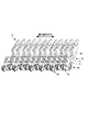
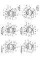
図7は、本実施形態に係る鍵盤楽器に適用されるハンマーユニットを示す概略図であり、図8は、本実施形態に係る鍵盤楽器に適用されるハンマー部材を示す概略図である。ここで、図8(a)、(b)は、白鍵用のハンマー部材を示す図であり、図8(c)、(d)は、黒鍵用のハンマー部材を示す図である。また、図9は、本実施形態に係る鍵盤楽器に適用される白鍵用のハンマーキャップを示す概略図であり、図10は、本実施形態に係る鍵盤楽器に適用される黒鍵用のハンマーキャップを示す概略図である。ここで、図9(a)、図10(a)は、ハンマーキャップの斜視図であり、図9(b)、図10(b)は、ハンマーキャップの側面図及び断面図である。   FIG. 7 is a schematic view showing a hammer unit applied to the keyboard instrument according to the present embodiment, and FIG. 8 is a schematic view showing a hammer member applied to the keyboard instrument according to the present embodiment. Here, FIGS. 8A and 8B are diagrams showing a hammer member for a white key, and FIGS. 8C and 8D are diagrams showing a hammer member for a black key. 9 is a schematic diagram showing a hammer cap for white keys applied to the keyboard instrument according to the present embodiment, and FIG. 10 is a hammer for black keys applied to the keyboard instrument according to the present embodiment. It is a schematic diagram showing a cap. Here, FIGS. 9A and 10A are perspective views of the hammer cap, and FIGS. 9B and 10B are a side view and a sectional view of the hammer cap.

ハンマーユニット12は、図3、図4、図7に示すように、複数の白鍵20及び黒鍵30のそれぞれに対する押鍵操作に応じて回動して各鍵にアクション荷重を付与する複数のハンマー部材40と、複数配列される白鍵20及び黒鍵30に対して共通に設けられ、各鍵に対応するハンマー部材40を支持軸42を介してそれぞれ回動可能に支持するハンマーホルダ60と、を備えている。ハンマーホルダ60は、鍵盤シャーシ10のユニット取付け部210の下面側に取り付けられている。   As shown in FIG. 3, FIG. 4, and FIG. 7, the hammer unit 12 is rotated in response to a key pressing operation on each of the plurality of white keys 20 and the plurality of black keys 30 to apply an action load to each key. A hammer member 40, and a hammer holder 60 that is provided in common for a plurality of white keys 20 and black keys 30 and that rotatably supports a hammer member 40 corresponding to each key via a support shaft 42. , Are provided. The hammer holder 60 is attached to the lower surface side of the unit attachment portion 210 of the keyboard chassis 10.

ハンマー部材40は、図7、図8(a)、(c)に示すように、金属材料からなるハンマー本体44と、ハンマー本体44の一端側(図8右端側)に設けられた力点部である鍵連結部50と、ハンマー本体44の他端側(図8左端側)に設けられた荷重点部である錘部46と、ハンマー本体44の錘部46と鍵連結部50との間に設けられ、ハンマー本体44を回動可能に支持する支持軸42と、を備えている。ここで、ハンマー部材40は、図7、図8(a)、(c)に示すように、白鍵用と黒鍵用とで略同等の外観を有しているが、白鍵20と黒鍵30の押鍵時の特性等に応じて、支持軸42から錘部46や鍵連結部50までの寸法や形状等が若干異なるように設計されている。   As shown in FIGS. 7, 8 (a) and 8 (c), the hammer member 40 includes a hammer body 44 made of a metal material and a force point portion provided on one end side (right end side in FIG. 8) of the hammer body 44. Between a certain key connection part 50, a weight part 46 which is a load point part provided on the other end side (the left end side in FIG. 8) of the hammer body 44, and between the weight part 46 of the hammer body 44 and the key connection part 50. And a support shaft 42 that rotatably supports the hammer body 44. Here, as shown in FIGS. 7, 8A, and 8C, the hammer member 40 has substantially the same appearance for the white key and the black key, but the white key 20 and the black key The size and shape of the support shaft 42 to the weight portion 46 and the key connecting portion 50 are designed to be slightly different depending on the characteristics of the key 30 when the key is pressed.

ハンマー部材40の錘部46は、図7、図8に示すように、錘部46と支持軸42との間のハンマー本体44に比較して、鍵の配列方向から見た平面形状、及び、鍵の配列方向の厚みが大きくなるように形成されていることにより、鍵に所定のアクション荷重を付与するための重量が設定されている。   As shown in FIG. 7 and FIG. 8, the weight portion 46 of the hammer member 40 has a planar shape viewed from the arrangement direction of the keys, as compared with the hammer body 44 between the weight portion 46 and the support shaft 42, and Since the keys are formed so as to have a large thickness in the arrangement direction, the weight for applying a predetermined action load to the keys is set.

ハンマー部材40の鍵連結部50は、図8に示すように、ハンマー本体44の一端側のキャップ取付け部48を覆うようにハンマーキャップ(接触部材)51が取り付けられている。ハンマーキャップ51は、鍵連結部50が係合されるハンマー連結部24、34を有する白鍵20及び黒鍵30よりも高い弾性を有するエラストマーやシリコン等の弾性部材が適用される。ここで、ハンマーキャップ51は、図8(b)、(d)、図9、図10に示すように、白鍵用と黒鍵用とで略同等の外観を有しているが、白鍵20と黒鍵30の押鍵時の特性等に応じて、外観形状や寸法等が若干異なるように設計されている。また、ハンマー本体44のキャップ取付け部48は、図8(b)、(d)に示すように、ハンマーキャップ51が取り付けられる先端部分が、後述するハンマーキャップ51の天面53方向(図面上方向)にL字状に屈曲した形状を有している。   A hammer cap (contact member) 51 is attached to the key connecting portion 50 of the hammer member 40 so as to cover the cap attaching portion 48 on one end side of the hammer body 44, as shown in FIG. As the hammer cap 51, an elastic member such as an elastomer or silicon having higher elasticity than the white key 20 and the black key 30 having the hammer connecting portions 24 and 34 with which the key connecting portion 50 is engaged is applied. Here, as shown in FIGS. 8B, 8D, 9 and 10, the hammer cap 51 has substantially the same appearance for the white key and the black key. The external shape and dimensions of the black key 20 and the black key 30 are designed to be slightly different depending on the characteristics when the key is pressed. Further, as shown in FIGS. 8B and 8D, in the cap attachment portion 48 of the hammer body 44, the tip end portion to which the hammer cap 51 is attached has a top surface 53 direction of the hammer cap 51 described later (upward direction in the drawing). ) Has an L-shaped bent shape.

ハンマーキャップ51は、具体的には図9、図10に示すように、ハンマー本体44のキャップ取付け部48が挿入されて装着固定される開口部52と、白鍵20又は黒鍵30のハンマー押圧部23、33に設けられるハンマー連結部24、34の貫通孔の上側の内壁に接触する天面(図面上面)53と、天面53の鍵の配列方向(図9(b)、図10(b)の左図及び右図の左右方向)の中央領域に、天面53の鍵の長手方向に沿って設けられた溝部54と、天面53の溝部54に沿って溝部54よりも上方に突出して設けられた端部側突出部(両端部)55と、ハンマー連結部24、34の貫通孔の下側の内壁に接触する底面に設けられた底面突出部56と、を備えている。   Specifically, as shown in FIGS. 9 and 10, the hammer cap 51 has an opening 52 into which the cap mounting portion 48 of the hammer body 44 is inserted and fixed, and a hammer pressing force of the white key 20 or the black key 30. The top surface (upper surface of the drawing) 53 that comes into contact with the upper inner wall of the through holes of the hammer connecting portions 24 and 34 provided in the portions 23 and 33, and the direction in which the keys of the top surface 53 are arranged (FIG. 9B, FIG. b) in the central region of the left and right views (left and right direction), the groove portion 54 is provided along the longitudinal direction of the key of the top surface 53, and along the groove portion 54 of the top surface 53 above the groove portion 54. It is provided with an end-side protrusion (both ends) 55 provided so as to protrude, and a bottom-face protrusion 56 provided on the bottom surface that comes into contact with the inner wall of the lower side of the through holes of the hammer connecting portions 24, 34.

ハンマーキャップ51の開口部52は、図9(b)、図10(b)の断面図に示すように、ハンマー本体44のキャップ取付け部48の形状に対応し、ハンマーキャップ51をキャップ取付け部48に取り付けた状態でキャップ取付け部48の先端部分が係止される内部形状を有している。天面53は、図9、図10に示すように、外方(図面上方)に突出した湾曲面を有し、溝部54は、天面53の湾曲面に沿って天面53よりも窪んだ連続する凹部により形成されている。また、端部側突出部55は、図9(b)、図10(b)に示すように、天面53において溝部54の鍵の配列方向に隣接する両端側に、溝部54よりも上方(図9(b)、図10(b)の中央図の湾曲する天面53に対して法線方向)に突出するとともに、ハンマーキャップ51の鍵の配列方向(図9(b)、図10(b)の左図及び右図の左右方向)に突出し、図9(a)、図10(a)に示すように、天面53の湾曲面に沿って連続する突出部により形成されている。底面突出部56は、図9(b)、図10(b)示すように、ハンマーキャップ51の底面(下面)において鍵の配列方向の中央領域から突出し、ハンマー連結部24、34の貫通孔の貫通方向(鍵の長手方向)に連続する突出部により形成されている。   The opening 52 of the hammer cap 51 corresponds to the shape of the cap mounting portion 48 of the hammer main body 44 as shown in the sectional views of FIGS. 9B and 10B. It has an internal shape such that the tip end portion of the cap attachment portion 48 is locked when attached to the. As shown in FIGS. 9 and 10, the top surface 53 has a curved surface protruding outward (upward in the drawing), and the groove portion 54 is recessed from the top surface 53 along the curved surface of the top surface 53. It is formed by a continuous recess. Further, as shown in FIGS. 9B and 10B, the end-side protruding portion 55 is located above the groove portion 54 on both end sides of the top surface 53 adjacent to the groove arrangement direction of the keys of the groove 54. While protruding in the direction normal to the curved top surface 53 in the central views of FIGS. 9B and 10B, the key arrangement direction of the hammer cap 51 (FIGS. 9B and 10B). It is formed by a protruding portion that projects in the left and right directions of FIG. 9B) and is continuous along the curved surface of the top surface 53 as shown in FIGS. 9A and 10A. As shown in FIG. 9B and FIG. 10B, the bottom surface projecting portion 56 projects from the central region in the key arrangement direction on the bottom surface (lower surface) of the hammer cap 51, and is formed in the through holes of the hammer connecting portions 24 and 34. It is formed by a protruding portion continuous in the penetrating direction (longitudinal direction of the key).

図11は、本実施形態に係る鍵盤楽器に適用されるハンマー部材と鍵との連結構造を示す概略図である。ここで、図11(a)、(b)は、白鍵側の連結構造を示す平面図及び断面図であり、図11(a)、(b)は、黒鍵側の連結構造を示す平面図及び断面図である。   FIG. 11 is a schematic diagram showing a connecting structure of a hammer member and a key applied to the keyboard instrument according to the present embodiment. Here, FIGS. 11A and 11B are a plan view and a cross-sectional view showing the connecting structure on the white key side, and FIGS. 11A and 11B are planes showing the connecting structure on the black key side. It is a figure and a sectional view.

上述したような形状を有するハンマー部材40の鍵連結部50と白鍵20又は黒鍵30のハンマー連結部24、34との連結構造は、図11に示すように、ハンマー連結部24、34の貫通孔にハンマー部材40の一端側のハンマーキャップ51が挿入されて係合されている。ここで、ハンマーキャップ51の天面53には、鍵の配列方向の中央領域に天面53の湾曲面に沿って鍵の長手方向に溝部54が設けられていることにより、天面53の溝部54の両端側が溝部54よりも上方に相対的に突出した端部側突出部55が設けられている。また、端部側突出部55は、鍵の配列方向(図11(a)、(c)の左右方向)にも突出して設けられていることにより、端部側突出部55の天面部分が幅広に形成されている。また、ハンマーキャップ51の底面には、ハンマー連結部24、34の貫通孔の貫通方向に連続して突出する底面突出部56が設けられている。   As shown in FIG. 11, the connecting structure of the key connecting portion 50 of the hammer member 40 and the hammer connecting portions 24 and 34 of the white key 20 or the black key 30 having the above-described shape is as shown in FIG. A hammer cap 51 on one end side of the hammer member 40 is inserted into and engaged with the through hole. Here, on the top surface 53 of the hammer cap 51, the groove portion 54 is provided in the longitudinal direction of the key along the curved surface of the top surface 53 in the central region of the key arrangement direction. Both end sides of 54 are provided with end-side projecting portions 55 that project relatively upward from the groove portion 54. Further, since the end-side protrusion 55 is provided so as to protrude also in the key arrangement direction (the left-right direction in FIGS. 11A and 11C), the top surface of the end-side protrusion 55 is It is formed wide. Further, the bottom surface of the hammer cap 51 is provided with a bottom surface projecting portion 56 that continuously projects in the penetrating direction of the through holes of the hammer connecting portions 24 and 34.

これにより、ハンマーキャップ51の端部側突出部55の天面部分がハンマー連結部24、34の貫通孔の上側の内壁24a、34aに対して広い面積を有して接触する。また、ハンマーキャップ51の端部側突出部55の天面部分に隣接する側面部分とハンマー連結部24、34の貫通孔の側方(鍵の配列方向)側の内壁24b、34bとのクリアランス(間隙)が小さく設定され、両者が極めて近接した状態、又は、端部側突出部55の側面部分が当該内壁24b、34bのいずれか一方に接触した状態に保持されている。また、ハンマーキャップ51の底面突出部56がハンマー連結部24、34の貫通孔の下側の内壁24c、34cに対して底面突出部56の突出頂点である線状又は点状領域の狭い面積で接触する。   As a result, the top surface portion of the end-side protruding portion 55 of the hammer cap 51 comes into contact with the inner walls 24a, 34a above the through holes of the hammer coupling portions 24, 34 with a large area. Further, the clearance between the side surface portion adjacent to the top surface portion of the end side protrusion 55 of the hammer cap 51 and the inner walls 24b and 34b on the side (key arrangement direction) side of the through holes of the hammer connecting portions 24 and 34 ( The gap) is set to be small, and both are extremely close to each other, or the side surface portion of the end side protrusion 55 is held in contact with either one of the inner walls 24b and 34b. In addition, the bottom surface protruding portion 56 of the hammer cap 51 has a narrow area of a linear or dotted area which is the protruding apex of the bottom surface protruding portion 56 with respect to the inner walls 24c and 34c below the through holes of the hammer coupling portions 24 and 34. Contact.

次に、上述したような鍵盤機構を備えた鍵盤楽器の動作について、図3、図4を参照して説明する。
ユーザが白鍵20及び黒鍵30の押鍵操作を行っていない状態(初期状態)においては、図3(a)、図4(a)に示すように、ハンマー部材40が荷重点部である錘部46の重量によって支持軸42を中心に反時計回りに回動するように付勢されて、ハンマー部材40の錘部46が鍵盤シャーシ10に設けられた下限ストッパ部224に当接して下限位置が規制される。また、ハンマー部材40の鍵連結部50が鍵のハンマー押圧部23、33を押し上げることにより、白鍵20及び黒鍵30を上限位置である初期位置に規制する。ここで、白鍵20の上限位置は、ハンマー部材40の錘部46が下限ストッパ部224の上面に当接するとともに、白鍵20の前脚部25のストッパ面27が鍵盤シャーシ10の上限ストッパ部206の下面に当接した位置に規制される。黒鍵30の上限位置は、ハンマー部材40の錘部46が下限ストッパ部224の上面に当接した位置に規制される。
Next, the operation of the keyboard instrument equipped with the above-described keyboard mechanism will be described with reference to FIGS.
In a state (initial state) in which the user has not pressed the white key 20 and the black key 30, the hammer member 40 is the load point portion as shown in FIGS. 3A and 4A. The weight of the weight portion 46 is urged to rotate counterclockwise about the support shaft 42, and the weight portion 46 of the hammer member 40 abuts on the lower limit stopper portion 224 provided on the keyboard chassis 10 to lower the lower limit. The position is restricted. Further, the key connecting portion 50 of the hammer member 40 pushes up the hammer pressing portions 23 and 33 of the key, thereby restricting the white key 20 and the black key 30 to the initial position which is the upper limit position. Here, at the upper limit position of the white key 20, the weight part 46 of the hammer member 40 abuts the upper surface of the lower limit stopper part 224, and the stopper surface 27 of the front leg part 25 of the white key 20 makes the upper limit stopper part 206 of the keyboard chassis 10. Is restricted to the position where it abuts the lower surface of the. The upper limit position of the black key 30 is restricted to a position where the weight portion 46 of the hammer member 40 contacts the upper surface of the lower limit stopper portion 224.

この状態においては、鍵連結部50のハンマーキャップ51の端部側突出部55の天面部分が、ハンマー連結部24、34の貫通孔の上側の内壁24a、34aに接触した状態が保持される。また、鍵の下面側に設けられたスイッチ押圧部22、32が、鍵盤シャーシ10に取り付けられたスイッチ部14に対して上方の位置に離間した状態が保持される。   In this state, the state in which the top surface portion of the end-side protruding portion 55 of the hammer cap 51 of the key connecting portion 50 is held in contact with the inner walls 24a and 34a above the through holes of the hammer connecting portions 24 and 34 is held. . Further, the switch pressing portions 22 and 32 provided on the lower surface side of the key are kept in a state of being separated from the switch portion 14 attached to the keyboard chassis 10 at an upper position.

次いで、ユーザが白鍵20又は黒鍵30を指で押して押鍵操作を行った状態においては、図3(b)、図4(b)に示すように、白鍵20又は黒鍵30が支持軸218、236を中心に時計回りに回動する。これにより、ハンマー部材40の鍵連結部50が鍵のハンマー押圧部23、33により荷重点部である錘部46の重量に抗して押し下げられて、ハンマー部材40が支持軸42を中心に時計回りに回動して錘部46が上昇するとともに、鍵にアクション荷重が付与される。このとき、ハンマー部材40の鍵連結部50のハンマーキャップ51は、ハンマー押圧部23、33が下方に押し下げられることにより、ハンマー連結部24、34の貫通孔内で摺動する。また、この押鍵操作においては、白鍵20又は黒鍵30の鍵の配列方向の横振れが白鍵ガイド部204、黒鍵ガイド部232により規制されて、白鍵20又は黒鍵30が上下方向に移動する。   Next, when the user presses the white key 20 or the black key 30 with his / her finger to perform the key pressing operation, as shown in FIGS. 3B and 4B, the white key 20 or the black key 30 is supported. It rotates clockwise about the shafts 218 and 236. As a result, the key connecting portion 50 of the hammer member 40 is pushed down by the hammer pressing portions 23 and 33 of the key against the weight of the weight portion 46 that is the load point portion, and the hammer member 40 is rotated around the support shaft 42. As the weight part 46 is raised by turning around, the action load is applied to the key. At this time, the hammer cap 51 of the key connecting portion 50 of the hammer member 40 slides in the through holes of the hammer connecting portions 24 and 34 when the hammer pressing portions 23 and 33 are pushed down. Further, in this key pressing operation, the lateral deviation of the white key 20 or the black key 30 in the arrangement direction of the keys is restricted by the white key guide portion 204 and the black key guide portion 232, so that the white key 20 or the black key 30 moves up and down. Move in the direction.

そして、押鍵操作に伴ってハンマー部材40の鍵連結部50が鍵のハンマー押圧部23、33によりさらに押し下げられると、ハンマー部材40の錘部46がさらに上昇して鍵盤シャーシ10に設けられた上限ストッパ部222に当接することによりハンマー部材40の回動が停止して上限位置が規制されるとともに、白鍵20及び黒鍵30の下限位置が規制される(鍵下限状態)。ここで、白鍵20の下限位置は、ハンマー部材40の錘部46が上限ストッパ部222の下面に当接し、さらに白鍵20が押し下げられて白鍵20の前脚部25のストッパ面28が鍵盤シャーシ10の下限ストッパ部208の上面に当接した位置に規制される。黒鍵30の下限位置は、ハンマー部材40の錘部46が上限ストッパ部222の下面に当接した位置に規制される。なお、本実施形態に示した鍵盤機構においては、鍵への押鍵操作によりハンマー部材40が支持軸42を中心に回動する際に、慣性モーメントによって鍵にアクション荷重を付与するために、ハンマー部材40は、支持軸42よりも錘部46側のハンマー本体44の長さが鍵連結部50側よりも十分に長くなるように設定されている。   Then, when the key connecting portion 50 of the hammer member 40 is further pushed down by the hammer pressing portions 23 and 33 of the key in accordance with the key pressing operation, the weight portion 46 of the hammer member 40 further rises and is provided on the keyboard chassis 10. When the hammer member 40 comes into contact with the upper limit stopper portion 222, the rotation of the hammer member 40 is stopped and the upper limit position is regulated, and the lower limit positions of the white key 20 and the black key 30 are regulated (key lower limit state). Here, at the lower limit position of the white key 20, the weight portion 46 of the hammer member 40 contacts the lower surface of the upper limit stopper portion 222, and the white key 20 is further pushed down so that the stopper surface 28 of the front leg portion 25 of the white key 20 is on the keyboard. It is restricted to a position where it abuts on the upper surface of the lower limit stopper portion 208 of the chassis 10. The lower limit position of the black key 30 is restricted to a position where the weight portion 46 of the hammer member 40 abuts the lower surface of the upper limit stopper portion 222. In the keyboard mechanism shown in the present embodiment, when the hammer member 40 rotates about the support shaft 42 by a key depression operation on the key, an action load is applied to the key by the moment of inertia, The member 40 is set such that the length of the hammer main body 44 on the weight portion 46 side of the support shaft 42 is sufficiently longer than that of the key connecting portion 50 side.

この押鍵操作において、ハンマー部材40の錘部46が上限ストッパ部222に当接するまでの間に、鍵盤シャーシ10に取り付けられたスイッチ部14が鍵のスイッチ押圧部22、32により押圧されることにより、スイッチ部14がオン動作してスイッチ信号を出力すると、楽音情報が生成されてスピーカから楽音の発音が開始される。   In this key depression operation, the switch portion 14 attached to the keyboard chassis 10 is pressed by the switch pressing portions 22 and 32 of the key before the weight portion 46 of the hammer member 40 contacts the upper limit stopper portion 222. As a result, when the switch unit 14 is turned on and outputs the switch signal, the musical tone information is generated and the pronunciation of the musical tone is started from the speaker.

その後、ユーザが白鍵20又は黒鍵30から指を離して押鍵操作を終了した場合には、ハンマー部材40が錘部46の重量によって支持軸42を中心に反時計回りに回動して、ハンマー部材40の鍵連結部50が鍵のハンマー押圧部23、33を押し上げ、錘部46が下限ストッパ部224の上面に当接することにより、白鍵20及び黒鍵30が上限位置である初期位置に再び規制される。   After that, when the user releases the finger from the white key 20 or the black key 30 to finish the key pressing operation, the hammer member 40 is rotated counterclockwise about the support shaft 42 by the weight of the weight portion 46. The key connecting portion 50 of the hammer member 40 pushes up the hammer pressing portions 23 and 33 of the key, and the weight portion 46 abuts on the upper surface of the lower limit stopper portion 224, so that the white key 20 and the black key 30 are at the upper limit position. Position is regulated again.

このような白鍵20及び黒鍵30の押鍵操作において、鍵のハンマー連結部24、34の貫通孔に係合されたハンマー部材40のハンマーキャップ51は、天面53の湾曲面に沿って設けられた溝部54により両端側に突出する幅広の端部側突出部55を有しているので、ハンマー連結部24、34の貫通孔の上側の内壁24a、34aに対して、端部側突出部55の天面部分が広い面積で接触して押し下げられるとともに、当該接触位置が天面53の湾曲面に沿って変化しながら摺動する。また、ハンマーキャップ51の端部側突出部55とハンマー連結部24、34の貫通孔の側方側の内壁24b、34bとのクリアランスが小さく設定されているので、端部側突出部55は、側面部分においてもハンマー連結部24、34の貫通孔内で対向する側方側の内壁24b、34bの一方に対して摺動する。また、ハンマーキャップ51は、底面に連続して突出する底面突出部56を有しているので、ハンマー連結部24、34の貫通孔の下側の内壁24c、34cに対して、狭い面積で接触しながら摺動する。   In such a key depression operation of the white key 20 and the black key 30, the hammer cap 51 of the hammer member 40 engaged with the through holes of the hammer connecting portions 24, 34 of the key is moved along the curved surface of the top surface 53. Since it has wide end-side protrusions 55 protruding toward both ends by the provided groove 54, the end-side protrusions are formed with respect to the inner walls 24a, 34a on the upper side of the through holes of the hammer connecting portions 24, 34. The top surface portion of the portion 55 contacts and is pushed down over a wide area, and the contact position slides while changing along the curved surface of the top surface 53. Further, since the clearance between the end side protrusion 55 of the hammer cap 51 and the inner walls 24b, 34b on the side of the through holes of the hammer connecting portions 24, 34 is set small, the end side protrusion 55 is Even in the side surface portion, it slides against one of the inner walls 24b and 34b on the side opposite to each other in the through holes of the hammer connecting portions 24 and 34. Further, since the hammer cap 51 has the bottom surface protruding portion 56 that continuously protrudes from the bottom surface, it contacts the inner walls 24c and 34c below the through holes of the hammer coupling portions 24 and 34 in a narrow area. While sliding.

このように、本実施形態においては、ハンマー連結部24、34の貫通孔内で、ハンマー部材40の鍵連結部50のハンマーキャップ51を、湾曲面を有する天面53において端部側突出部55により広い面積で接触させるとともに、側面におけるクリアランスを小さくして安定して摺動させることができ、また、底面において底面突出部56により狭い面積で接触させて大きな摩擦抵抗が生じないようにして円滑に摺動させることができる。これにより、ハンマー部材40と鍵との連結状態を良好に保持して回動させることができ、押鍵時の異常な振動や異音等の不具合の発生を抑制しつつ、ハンマー部材40の回動時における横ブレを抑制して押鍵操作に伴う力を適切にハンマー部材40に伝達することができる。   As described above, in the present embodiment, the hammer cap 51 of the key connecting portion 50 of the hammer member 40 is inserted into the through holes of the hammer connecting portions 24, 34, and the end side protrusion 55 is formed on the top surface 53 having the curved surface. This allows a wider area to be contacted, a smaller clearance on the side surface to allow stable sliding, and a bottom surface protrusion 56 on the bottom surface to contact in a narrow area to prevent large frictional resistance and smooth the surface. Can be slid on. As a result, the hammer member 40 and the key can be favorably held and rotated, and the hammer member 40 can be rotated while suppressing the occurrence of troubles such as abnormal vibration and noise when the key is pressed. It is possible to suppress lateral shake during movement and appropriately transmit the force associated with the key pressing operation to the hammer member 40.

また、本実施形態においては、ユーザが鍵を強打した場合等においても、弾性部材からなるハンマーキャップ51に設けられた溝部54の両端側に突出する端部側突出部55により衝撃が吸収又は緩和されるので、ハンマーキャップ51の変形や回転、脱落等を抑制することができる。特に、ハンマーキャップ51が取り付けられるハンマー本体44のキャップ取付け部48の先端部分がハンマーキャップ51の天面53方向にL字状に屈曲した形状を有しているので、ハンマーキャップ51に変形が生じた場合であっても回転や脱落等を良好に防止することができる。   Further, in the present embodiment, even when the user swipes the key, the impact is absorbed or mitigated by the end-side protrusions 55 protruding toward both ends of the groove 54 provided in the hammer cap 51 made of an elastic member. Therefore, the hammer cap 51 can be prevented from being deformed, rotated, and dropped. In particular, since the tip end portion of the cap attachment portion 48 of the hammer body 44 to which the hammer cap 51 is attached has a shape bent in an L shape toward the top surface 53 of the hammer cap 51, the hammer cap 51 is deformed. Even in the case of rotation, it is possible to favorably prevent rotation, dropout, and the like.

また、本実施形態においては、ハンマー部材40のハンマーキャップ51の天面53に溝部54を設けるとともに、鍵の配列方向に突出させた端部側突出部55を有しているので、ハンマーキャップ51の成形材料の使用量を増やすことなく、ハンマー連結部24、34の貫通孔内での摺動による摩擦を抑制しつつ、幅広の天面53を有するハンマーキャップ51を実現することができる。また、天面53の溝部54の両端側に幅広の端部側突出部55が形成されているので、ハンマーキャップ51の天面53のクッション性(弾力性)が増してハンマー部材40にしなりを生じさせて、ハンマー部材40の慣性モーメントを上げることができる。   In addition, in the present embodiment, the groove 54 is provided on the top surface 53 of the hammer cap 51 of the hammer member 40, and the end side protruding portion 55 protruding in the key arrangement direction is provided. It is possible to realize the hammer cap 51 having the wide top surface 53 while suppressing the friction due to the sliding of the hammer connecting portions 24 and 34 in the through holes without increasing the amount of the molding material used. In addition, since wide end-side protrusions 55 are formed on both ends of the groove 54 of the top surface 53, the cushioning property (elasticity) of the top surface 53 of the hammer cap 51 is increased, and the hammer member 40 is not bent. It can be generated to increase the moment of inertia of the hammer member 40.

また、本実施形態においては、ハンマーキャップ51の天面53に設けられた溝部54に潤滑剤を充填、保持することにより潤滑剤溜まりとして適用することができる。さらに、ハンマー部材40のハンマーキャップ51がハンマー連結部24、34の貫通孔内で摺動する際に、貫通孔の上側の内壁24a、34aから突出する鍵側突出部29、36が溝部54内を移動して、溝部54に保持された潤滑剤を掻き分けることにより、溝部54に隣接する端部側突出部55に適切に潤滑剤を補給、浸透させることができ、ハンマーキャップ51の摩耗を抑制しつつ、ハンマーキャップ51を円滑に摺動させることができる。ここで、鍵側突出部29、36とハンマーキャップ51の溝部54の内壁とのクリアランスを、ハンマーキャップ51の端部側突出部55の側面部分とハンマー連結部24、34の貫通孔の内壁24b、34bとのクリアランスよりも大きく設定することにより、鍵側突出部29、36を溝部54の内壁に接触することなく移動させることができるので、摩擦による摩耗や抵抗によってハンマーキャップ51の摺動が妨げられることがない。   Further, in the present embodiment, the groove 54 provided on the top surface 53 of the hammer cap 51 can be applied as a lubricant reservoir by filling and holding the lubricant. Further, when the hammer cap 51 of the hammer member 40 slides in the through holes of the hammer connecting portions 24, 34, the key side protruding portions 29, 36 protruding from the inner walls 24a, 34a on the upper side of the through holes are provided in the groove portions 54. And the lubricant retained in the groove 54 is scraped off, the lubricant can be appropriately replenished and permeated into the end side protrusion 55 adjacent to the groove 54, and the wear of the hammer cap 51 is prevented. The hammer cap 51 can be smoothly slid while restraining it. Here, the clearance between the key-side protrusions 29 and 36 and the inner wall of the groove 54 of the hammer cap 51 is determined by the side surface portion of the end-side protrusion 55 of the hammer cap 51 and the inner wall 24b of the through hole of the hammer coupling portions 24 and 34. , 34b, the key side protrusions 29, 36 can be moved without coming into contact with the inner wall of the groove 54, so that the hammer cap 51 can be slid by frictional wear or resistance. There is no hindrance.

なお、本実施形態においては、ハンマーキャップ51の天面53に鍵の配列方向に突出した端部側突出部55が設けられているが、鍵盤ユニット104の組付け時にハンマー部材40の鍵連結部50をハンマー連結部24、34の貫通孔に良好に挿入して係合させるために、図9(a)及び図9(b)の右図、又は、図10(a)及び図10(b)の右図に示すように、貫通孔への挿入方向(図面手前方向)に向けて端部側突出部55の幅寸法(鍵の配列方向への突出寸法)が小さくなるテーパ形状を適用するものであってもよい。   In the present embodiment, the top surface 53 of the hammer cap 51 is provided with the end-side protruding portion 55 protruding in the key arrangement direction, but when the keyboard unit 104 is assembled, the key connecting portion of the hammer member 40 is attached. In order to satisfactorily insert the 50 into the through holes of the hammer connecting portions 24 and 34 and engage them, the right view of FIGS. 9 (a) and 9 (b), or FIGS. 10 (a) and 10 (b). ), A taper shape in which the width dimension (projection dimension in the key arrangement direction) of the end side projecting portion 55 decreases toward the insertion direction into the through hole (front side in the drawing) is applied. It may be one.

<第2の実施形態>
次に、本発明に係る鍵盤楽器の第2の実施形態について説明する。ここで、上述した第1の実施形態と同等の構成や動作についてはその説明を簡略化する。
図12は、第2の実施形態に係る鍵盤楽器に適用されるハンマーキャップを示す概略図である。
<Second Embodiment>
Next, a second embodiment of the keyboard musical instrument according to the present invention will be described. Here, the description of the same configurations and operations as those of the above-described first embodiment will be simplified.
FIG. 12 is a schematic view showing a hammer cap applied to the keyboard musical instrument according to the second embodiment.

上述した第1の実施形態においては、鍵の押鍵操作に応じて、ハンマー部材40のハンマーキャップ51が鍵のハンマー連結部24、34の貫通孔内で摺動する際に、貫通孔内に突出して設けられた鍵側突出部29、36をハンマーキャップ51の溝部54の内壁に接触させることなく移動させる形態について説明した。第2の実施形態においては、ハンマーキャップ51の溝部54内に突出部が設けられ、ハンマーキャップ51がハンマー連結部24、34の貫通孔内で摺動する際に、所定のタイミングで鍵側突出部29、36と溝部54内の突出部とが所定の抵抗を有して接触する形態を有している。   In the above-described first embodiment, when the hammer cap 51 of the hammer member 40 slides in the through holes of the hammer connecting portions 24, 34 of the key in response to the key pressing operation, the inside of the through holes is formed. The mode in which the key side protrusions 29 and 36 provided so as to protrude are moved without contacting the inner wall of the groove 54 of the hammer cap 51 has been described. In the second embodiment, the protruding portion is provided in the groove portion 54 of the hammer cap 51, and when the hammer cap 51 slides in the through holes of the hammer coupling portions 24 and 34, the key side protrusion occurs at a predetermined timing. The parts 29 and 36 and the protrusion in the groove 54 are in contact with each other with a predetermined resistance.

本実施形態においては、ハンマー部材40のハンマーキャップ51は、図12に示すように、上述した第1の実施形態に示したハンマーキャップと同等の構成に加え、天面53の鍵の長手方向(又は、天面53の湾曲方向)に沿って設けられた溝部(第1の実施形態に示した溝部54に対応し、本実施形態では端部側突出部55間にあって、後述する溝部突出部57が設けられる溝部全体を指す;便宜的に「溝部54」と記す)内に、溝部54の両端側に形成される端部側突出部55相互を、鍵の配列方向(図12(b)、(d)の紙面に垂直方向)に連結するように突出する溝部突出部(中央突出部)57を備えている。これにより、天面53に設けられた溝部54が溝部突出部57により2つに分割されて、鍵の長手方向に沿って溝部(第1溝部)54aと溝部(第2溝部)54bとが形成されている。   In the present embodiment, as shown in FIG. 12, the hammer cap 51 of the hammer member 40 has the same configuration as that of the hammer cap shown in the above-described first embodiment, as well as the longitudinal direction of the key of the top surface 53 ( Alternatively, it corresponds to the groove portion (the groove portion 54 shown in the first embodiment) provided along the curved direction of the top surface 53, and in the present embodiment, it is between the end portion side protrusion portions 55 and is described later. In FIG. 12 (b), the end side protrusions 55 formed on both ends of the groove 54 are arranged in the direction of arrangement of the keys (FIG. 12 (b), It is provided with a groove protruding portion (central protruding portion) 57 protruding so as to be connected in a direction perpendicular to the paper surface of (d). As a result, the groove portion 54 provided on the top surface 53 is divided into two by the groove portion protruding portion 57, and a groove portion (first groove portion) 54a and a groove portion (second groove portion) 54b are formed along the longitudinal direction of the key. Has been done.

具体的には、白鍵用のハンマーキャップ51においては、例えば図12(a)、(b)に示すように、溝部54a、54bのそれぞれの大きさが略同等になるように、溝部突出部57の位置が設定されている。また、黒鍵用のハンマーキャップ51においては、例えば図12(c)、(d)に示すように、溝部54bが溝部54aよりも大きくなるように、溝部突出部57の位置が設定されている。又は、溝部54aがなく溝部54bのみが形成されるように、溝部突出部57の位置が溝部54の一方の端部(図12(d)の左方端)に設定されている。   Specifically, in the hammer cap 51 for a white key, as shown in FIGS. 12 (a) and 12 (b), for example, the groove portions 54a and 54b are formed so that the groove portions have substantially the same size. The position of 57 is set. Further, in the hammer cap 51 for a black key, as shown in, for example, FIGS. 12C and 12D, the position of the groove protruding portion 57 is set so that the groove 54b is larger than the groove 54a. . Alternatively, the position of the groove projecting portion 57 is set at one end of the groove 54 (the left end in FIG. 12D) so that only the groove 54b is formed without the groove 54a.

ここで、詳しくは後述するが、溝部突出部57は、鍵の押鍵操作に応じて、ハンマー部材40のハンマーキャップ51が鍵のハンマー連結部24、34の貫通孔内で摺動する際に、ハンマー連結部24の貫通孔内に突出して設けられた鍵側突出部29、36に所定のタイミングで所定の抵抗(摩擦抵抗)を有して接触するように、溝部54内での設置位置や突出高さ、断面形状等が設定される。   Here, as will be described later in detail, the groove protrusion 57 is formed when the hammer cap 51 of the hammer member 40 slides in the through holes of the hammer connecting portions 24 and 34 of the key in response to a key pressing operation. An installation position in the groove portion 54 so that the key-side protruding portions 29 and 36 provided to protrude into the through hole of the hammer connecting portion 24 are brought into contact with each other with predetermined resistance (friction resistance) at predetermined timing. The protruding height, cross-sectional shape, etc. are set.

なお、本実施形態においては、溝部突出部57として、図12(a)、(c)に示すように、溝部54の両端側に形成される端部側突出部55相互を鍵の配列方向に連結したものを示したが、貫通孔内に突出して設けられた鍵側突出部29、36の位置や突出高さ、断面形状等に対応するように、少なくとも溝部54において鍵の配列方向の中央付近に突出して設けられているものであればよい。また、溝部突出部57は、ハンマーキャップ51と同一の弾性部材により形成されているものであってもよいし、溝部突出部57が別の特性(例えばハンマーキャップ51よりも高い剛性)を有する部材により形成されているものであってもよい。   In this embodiment, as the groove protrusions 57, as shown in FIGS. 12A and 12C, the end protrusions 55 formed on both ends of the groove 54 are arranged in the key arrangement direction. The connection is shown, but at least in the groove portion 54 in the center of the arrangement direction of the keys so as to correspond to the positions, the protruding heights, the cross-sectional shapes, and the like of the key-side protruding portions 29 and 36 that are provided so as to project into the through holes. Anything can be used as long as it is provided so as to project in the vicinity. Further, the groove projecting portion 57 may be formed of the same elastic member as the hammer cap 51, or the groove projecting portion 57 has another characteristic (for example, rigidity higher than that of the hammer cap 51). It may be formed by.

次に、上述したような鍵盤機構を備えた鍵盤楽器の動作について説明する。
図13は、本実施形態に係る鍵盤楽器に適用される白鍵の鍵盤機構を示す概略断面図であり、図14は、本実施形態に係る鍵盤楽器に適用される黒鍵の鍵盤機構を示す概略断面図である。ここで、図13(a)〜(c)は、白鍵におけるレットオフフィール前後における鍵盤機構の状態を示す図であり、図14(a)〜(c)は、黒鍵におけるレットオフフィール前後における鍵盤機構の状態を示す図である。なお、本実施形態において、押鍵操作を行っていない初期状態(上限位置)、及び、押鍵操作における鍵の下限位置については、上述した第1の実施形態に示した図3及び図4と同等であるので、図示を省略する。図15は、本実施形態に係る鍵盤楽器に適用されるハンマー部材と鍵との連結状態を示す概略図である。ここで、図15(a)〜(c)は、白鍵におけるレットオフフィール前後における連結状態の変化を示す断面図であり、図15(d)〜(f)は、黒鍵におけるレットオフフィール前後における連結構造の変化を示す断面図である。
Next, the operation of the keyboard musical instrument having the above-described keyboard mechanism will be described.
FIG. 13 is a schematic cross-sectional view showing a white key keyboard mechanism applied to the keyboard instrument according to this embodiment, and FIG. 14 shows a black key keyboard mechanism applied to the keyboard instrument according to this embodiment. It is a schematic sectional drawing. Here, FIGS. 13A to 13C are diagrams showing the states of the keyboard mechanism before and after the let-off feel in the white key, and FIGS. 14A to 14C are keyboards before and after the let-off feel in the black key. It is a figure which shows the state of a mechanism. In the present embodiment, the initial state (upper limit position) in which no key depression operation is performed and the lower limit position of the key in the key depression operation are the same as those in FIG. 3 and FIG. 4 shown in the above-described first embodiment. Since they are equivalent, illustration is omitted. FIG. 15 is a schematic diagram showing a connected state of a hammer member and a key applied to the keyboard instrument according to the present embodiment. Here, FIGS. 15A to 15C are cross-sectional views showing changes in the connection state before and after the let-off feel in the white key, and FIGS. 15D to 15F are before and after the let-off feel in the black key. It is sectional drawing which shows the change of a connection structure.

本実施形態に係る鍵盤ユニットに適用される鍵盤機構は、図13、図14に示すように、上述した第1の実施形態に示した白鍵20及び黒鍵30と同等の鍵盤機構(図3、図4参照)において、図12に示した溝部突出部57が設けられたハンマーキャップ51が、ハンマー部材40の鍵連結部50に適用されている。   As shown in FIGS. 13 and 14, the keyboard mechanism applied to the keyboard unit according to the present embodiment is equivalent to the white key 20 and the black key 30 shown in the above-described first embodiment (FIG. 3). 4), the hammer cap 51 provided with the groove projecting portion 57 shown in FIG. 12 is applied to the key connecting portion 50 of the hammer member 40.

本実施形態に係る鍵盤機構を備えた鍵盤楽器の動作は、上述した第1の実施形態と同様に、ユーザが押鍵操作を行っておらず、鍵が上限位置にある初期状態(図3(a)、図4(a))と、図13、図14に示すように、押鍵操作に伴って楽音の発音を開始する状態と、押鍵操作により鍵が下限位置に達した鍵下限状態(図3(b)、図4(b))と、の間を変化する。   The operation of the keyboard instrument having the keyboard mechanism according to the present embodiment is the same as in the first embodiment described above, in which the user does not perform the key depression operation and the key is in the upper limit position (see FIG. a), FIG. 4A), and a state in which a musical tone is started to be generated in response to a key depression operation, and a key lower limit state in which the key reaches the lower limit position by the key depression operation, as shown in FIGS. 13 and 14. (FIG. 3 (b), FIG. 4 (b)).

ユーザが押鍵操作を行っていない初期状態においては、図3(a)、図4(a)に示した状態と同様に、ハンマー部材40の錘部46の重量により、ハンマー部材40は、錘部46が下限ストッパ部224に当接した下限位置に規制されるとともに、鍵連結部50が鍵のハンマー押圧部23、33を押し上げることにより、白鍵20及び黒鍵30を上限位置(初期位置)に規制する。このとき、ハンマー部材40の鍵連結部50と白鍵20及び黒鍵30のハンマー連結部24、34との連結状態は、上述した第1の実施形態と同様に、鍵連結部50のハンマーキャップ51の端部側突出部55の天面部分が、ハンマー連結部24、34の貫通孔の上側の内壁24a、34aに接触した状態が保持される。また、ハンマーキャップ51の底面に設けられる底面突出部56が、ハンマー連結部24、34の貫通孔の下側の内壁24c、34cに接触した状態が保持される。   In the initial state in which the user does not perform the key depression operation, the hammer member 40 is moved by the weight of the weight portion 46 of the hammer member 40 as in the state shown in FIGS. 3A and 4A. The part 46 is regulated to the lower limit position where it abuts the lower limit stopper part 224, and the key connecting part 50 pushes up the hammer pressing parts 23 and 33 of the key to move the white key 20 and the black key 30 to the upper limit position (initial position). ). At this time, the connection state between the key connecting portion 50 of the hammer member 40 and the hammer connecting portions 24 and 34 of the white key 20 and the black key 30 is the same as in the above-described first embodiment, that is, the hammer cap of the key connecting portion 50. The top surface portion of the end side protruding portion 55 of 51 is held in contact with the inner walls 24a, 34a above the through holes of the hammer connecting portions 24, 34. Further, the state in which the bottom surface protruding portion 56 provided on the bottom surface of the hammer cap 51 is held in contact with the inner walls 24c, 34c below the through holes of the hammer connecting portions 24, 34 is held.

この初期状態においては、ハンマー連結部24、34の貫通孔の上側の内壁24a、34aに突出して設けられた鍵側突出部29、36は、ハンマーキャップ51の天面53に設けられた溝部54b内にあって、溝部54bの内壁や溝部突出部57には接触していない。   In this initial state, the key-side protrusions 29 and 36 provided so as to protrude from the inner walls 24a and 34a above the through holes of the hammer coupling portions 24 and 34 are provided with the groove 54b provided on the top surface 53 of the hammer cap 51. It is inside and is not in contact with the inner wall of the groove portion 54b or the groove portion protruding portion 57.

次いで、ユーザが押鍵操作を行い、楽音の発音が開始される状態においては、図13、図14に示すように、ハンマー部材40の錘部46が上昇して上限ストッパ部222に当接するまでの間に、白鍵20及び黒鍵30の下面側に設けられたスイッチ押圧部22、32により鍵盤シャーシ10に取り付けられたスイッチ部14が押圧されることにより、スイッチ部14がオン動作してスイッチ信号が出力され、楽音情報が生成されてスピーカから楽音の発音が開始される。   Next, in the state in which the user performs a key depression operation to start producing a musical sound, as shown in FIGS. 13 and 14, until the weight portion 46 of the hammer member 40 rises and comes into contact with the upper limit stopper portion 222. During this period, the switch parts 14 attached to the keyboard chassis 10 are pressed by the switch pressing parts 22 and 32 provided on the lower surface side of the white key 20 and the black key 30, whereby the switch part 14 is turned on. The switch signal is output, the musical tone information is generated, and the pronunciation of the musical tone is started from the speaker.

このとき、ハンマー部材40の鍵連結部50と鍵のハンマー連結部24、34との連結状態は、まず、図13(a)、図14(a)及び図15(a)、(d)に示すように、少なくともハンマーキャップ51の端部側突出部55がハンマー連結部24、34の貫通孔の上側の内壁24a、34aに摺接した状態で、ハンマーキャップ51がハンマー連結部24、34の貫通孔内で摺動して、貫通孔に設けられた鍵側突出部29、36がハンマーキャップ51の溝部54b側から鍵の長手方向に溝部突出部57に当接する。   At this time, the connection state between the key connecting portion 50 of the hammer member 40 and the key hammer connecting portions 24 and 34 is as shown in FIGS. 13 (a), 14 (a), 15 (a), and 15 (d). As shown, at least the end side protrusion 55 of the hammer cap 51 is in sliding contact with the inner walls 24a, 34a of the upper side of the through holes of the hammer connecting portions 24, 34, the hammer cap 51 of the hammer connecting portions 24, 34. By sliding in the through hole, the key-side protrusions 29, 36 provided in the through-hole abut on the groove protrusion 57 in the longitudinal direction of the key from the groove 54b side of the hammer cap 51.

次いで、図13(b)、図14(b)及び図15(b)、(e)に示すように、ハンマーキャップ51がハンマー連結部24、34の貫通孔内でさらに摺動すると、鍵側突出部29、36が溝部突出部57に乗り上げて、鍵連結部50を押し下げる方向に圧接する。この状態においては、貫通孔に設けられた鍵側突出部29、36は、ハンマーキャップ51の溝部54b側から溝部突出部57に接触して所定の抵抗を生じる。   Next, as shown in FIGS. 13 (b), 14 (b), 15 (b), and (e), when the hammer cap 51 further slides in the through holes of the hammer connecting portions 24 and 34, the key side The projecting portions 29 and 36 ride on the groove projecting portion 57 and are pressed against the key connecting portion 50 in the direction of pushing it down. In this state, the key-side protrusions 29 and 36 provided in the through holes come into contact with the groove protrusions 57 from the groove 54b side of the hammer cap 51 to generate a predetermined resistance.

具体的には、鍵側突出部29、36は溝部突出部57に対して溝部54b側から当接した状態から、溝部突出部57の表面に沿って摺接しながら乗り上がる。これにより、鍵側突出部29、36と溝部突出部57との間に摩擦抵抗が生じるとともに、鍵連結部50が押し下げられてハンマーキャップ51の底面突出部56がハンマー連結部24、34の貫通孔の下側の内壁24c、34cに摺接した状態で、ハンマーキャップ51が貫通孔内で摺動する。このとき、ハンマーキャップ51の溝部突出部57は、鍵側突出部29、36により圧接されて、突出頂点付近を中心にして変形が生じる。   Specifically, the key-side protrusions 29, 36 ride on the groove protrusion 57 while sliding along the surface of the groove protrusion 57 from the state of contacting the groove protrusion 57 from the groove 54b side. As a result, frictional resistance is generated between the key-side protrusions 29 and 36 and the groove protrusion 57, and the key connecting portion 50 is pushed down so that the bottom surface protruding portion 56 of the hammer cap 51 penetrates the hammer connecting portions 24 and 34. The hammer cap 51 slides in the through hole while being in sliding contact with the inner walls 24c and 34c on the lower side of the hole. At this time, the groove projecting portion 57 of the hammer cap 51 is pressed against the key-side projecting portions 29 and 36 to be deformed around the projecting apex.

次いで、図13(c)、図14(c)及び図15(c)、(f)に示すように、ハンマーキャップ51がハンマー連結部24、34の貫通孔内でさらに摺動すると、鍵側突出部29、36が溝部突出部57を乗り越える。この状態においては、貫通孔に設けられた鍵側突出部29、36は、溝部突出部57との間に生じていた抵抗から一気に開放される。このとき、ハンマー押圧部23、33及び鍵連結部50に衝撃が生じて、ハンマー押圧部23、33を介して白鍵20及び黒鍵30の上面21、31に指を載せているユーザに、クリック感として伝達される。   Then, as shown in FIGS. 13 (c), 14 (c) and 15 (c), (f), when the hammer cap 51 slides further in the through holes of the hammer connecting portions 24, 34, the key side The protrusions 29 and 36 ride over the groove protrusion 57. In this state, the key side protrusions 29 and 36 provided in the through holes are released all at once from the resistance generated between the key side protrusions 29 and 36. At this time, an impact is generated on the hammer pressing portions 23 and 33 and the key connecting portion 50, and a user who puts his / her finger on the upper surfaces 21 and 31 of the white keys 20 and the black keys 30 through the hammer pressing portions 23 and 33, It is transmitted as a click feeling.

すなわち、鍵側突出部29、36が、図15(a)、(d)に示したように溝部突出部57に当接した状態から、図15(b)、(e)に示したように溝部突出部57に乗り上げる際に、ユーザが白鍵20及び黒鍵30を押鍵する荷重(アクション荷重)が増加して、溝部突出部57の突出頂点付近で当該荷重が最大となり、図15(c)、(f)に示したように溝部突出部57を乗り越えることにより当該荷重が減少することによりクリック感が生じる。このクリック感は、アコースティックピアノ等を演奏する際に、鍵盤をゆっくり押し込んだときに感じる独特の操作感である、レットオフフィールに相当するものである。すなわち、電子鍵盤楽器において、アコースティックピアノと同様の鍵盤の操作感(レットオフフィール)が再現される。   That is, as shown in FIGS. 15B and 15E, the key-side protrusions 29 and 36 contact the groove protrusion 57 as shown in FIGS. 15A and 15D. When the user rides on the groove protrusion 57, the load (action load) by which the user presses the white key 20 and the black key 30 increases, and the load becomes maximum near the protrusion apex of the groove protrusion 57. As shown in (c) and (f), the feeling of clicking is generated because the load is reduced by getting over the groove projecting portion 57. This click feeling corresponds to a let-off feel, which is a unique operation feeling that is felt when the keyboard is pushed in slowly when playing an acoustic piano or the like. That is, the electronic keyboard musical instrument reproduces a keyboard operation feeling (let-off feel) similar to that of an acoustic piano.

ここで、図15に示したように、貫通孔に設けられた鍵側突出部29、36が溝部突出部57に接触するタイミングは、図13、図14に示したように、押鍵操作において、上述した楽音の発音開始のタイミングの前後から鍵下限状態に至るまでの期間に設定される。具体的なタイミングの設定方法は、溝部54の鍵の長手方向(又は、天面53の湾曲方向)における溝部突出部57の設置位置や断面形状、又は、貫通孔の貫通方向(鍵の長手方向)における鍵側突出部29、36の設置位置や断面形状等のうち、少なくともいずれかを調整することにより実現される。これにより、楽音の発音開始のタイミングの前後から鍵下限状態に至るまでの期間のうちの、任意のタイミングで鍵側突出部29、36を溝部突出部57に接触させて、ユーザにクリック感を伝達することができる。   Here, as shown in FIG. 15, the timing at which the key-side protrusions 29, 36 provided in the through holes come into contact with the groove protrusion 57 is, as shown in FIGS. , Is set to a period from before and after the above-described timing of starting the sound generation of the musical sound to the key lower limit state. The specific timing setting method is as follows: the installation position and sectional shape of the groove protrusion 57 in the longitudinal direction of the key of the groove 54 (or the bending direction of the top surface 53), or the penetrating direction of the through hole (the longitudinal direction of the key). It is realized by adjusting at least one of the installation position and the cross-sectional shape of the key side protrusions 29 and 36 in FIG. As a result, the key-side protrusions 29 and 36 are brought into contact with the groove protrusions 57 at any timing within the period from before and after the timing of starting the generation of the musical tone until the key lower limit state is reached, and the user feels a click. Can be communicated.

また、鍵側突出部29、36が溝部突出部57に接触した際にユーザに伝達されるクリック感は、鍵側突出部29、36が溝部突出部57に接触した際に生じる抵抗の大きさや性質等により設定される。具体的なクリック感の調整方法は、溝部54に設けられる溝部突出部57の突出高さや断面形状、材質(硬度)、又は、貫通孔に設けられる鍵側突出部29、36の突出高さや断面形状、材質(硬度)等のうち、少なくともいずれかを調整することにより実現される。これにより、ユーザに伝達されるクリック感の強弱等の感触を任意に設定することができる。   Further, the click feeling transmitted to the user when the key-side protrusions 29 and 36 contact the groove protrusion 57 is the amount of resistance generated when the key-side protrusions 29 and 36 contact the groove protrusion 57. It is set according to the nature. A specific method for adjusting the click feeling is as follows. The protrusion height and the sectional shape of the groove protrusion 57 provided in the groove 54, the material (hardness), or the protrusion height and the cross section of the key side protrusions 29 and 36 provided in the through holes. It is realized by adjusting at least one of the shape, the material (hardness) and the like. As a result, it is possible to arbitrarily set the feeling of the click feeling transmitted to the user.

また、鍵側突出部29、36が溝部突出部57に接触した後、乗り越える際には、鍵連結部50をハンマー連結部24、34の貫通孔の下側の内壁24c、34cに押し付ける方向に力が生じる。本実施形態においては、ハンマーキャップ51の底面に、ハンマー連結部24、34の貫通孔の貫通方向に連続して突出する底面突出部56を設けていることにより、ハンマーキャップ51の底面と貫通孔の下側の内壁24c、34cとの間に大きな摩擦抵抗が生じないようにして、ハンマー連結部24、34の貫通孔内で鍵連結部50のハンマーキャップ51を円滑に摺動させることができる。   In addition, when the key-side protrusions 29 and 36 come into contact with the groove protrusion 57 and then get over, the key connecting portion 50 is pushed in the direction in which it is pressed against the inner walls 24c and 34c below the through holes of the hammer connecting portions 24 and 34. Power is generated. In the present embodiment, the bottom surface of the hammer cap 51 is provided with the bottom surface projecting portion 56 that continuously projects in the penetrating direction of the through holes of the hammer coupling portions 24 and 34, so that the bottom surface of the hammer cap 51 and the through hole are formed. It is possible to smoothly slide the hammer cap 51 of the key connecting portion 50 in the through holes of the hammer connecting portions 24 and 34 without causing a large frictional resistance between the lower inner walls 24c and 34c. .

次いで、ユーザが鍵をさらに押し込むと、図3(b)、図4(b)に示した状態と同様に、ハンマー部材40の錘部46がさらに上昇して上限ストッパ部222に当接して上限位置が規制されるとともに、白鍵20及び黒鍵30の下限位置が規制される鍵下限状態に移行する。このとき、ハンマー部材40の鍵連結部50と鍵のハンマー連結部24、34との連結状態は、上述した第1の実施形態と同様に、ハンマーキャップ51の端部側突出部55及び底面突出部56がハンマー連結部24、34の貫通孔の上側の内壁24a、34a及び下側の内壁24c、34cに摺接した状態で、ハンマーキャップ51が貫通孔内で摺動する。   Next, when the user further pushes the key, the weight portion 46 of the hammer member 40 further rises and abuts on the upper limit stopper portion 222 so that the upper limit is reached, as in the state shown in FIGS. 3B and 4B. While the positions are regulated, the lower limit state of the white key 20 and the black key 30 is regulated, and the state moves to the key lower limit state. At this time, the connection state between the key connecting portion 50 of the hammer member 40 and the key hammer connecting portions 24 and 34 is the same as in the above-described first embodiment, and the end side protruding portion 55 and the bottom surface protruding portion 55 of the hammer cap 51. The hammer cap 51 slides in the through holes with the portion 56 slidingly contacting the inner walls 24a, 34a on the upper side and the inner walls 24c, 34c on the lower side of the through holes of the hammer connecting portions 24, 34.

また、この鍵下限状態においては、貫通孔に設けられた鍵側突出部29、36がハンマーキャップ51の溝部突出部57を乗り越えて、溝部54a内にあって、溝部54aの内壁や溝部突出部57には接触していない、又は、抵抗や応力を生じることなく接触している。その後、ユーザが押鍵操作を終了すると、ハンマー部材40の錘部46が下降することにより鍵連結部50が鍵のハンマー押圧部23、33を押し上げ、錘部46が下限ストッパ部224に当接することにより、白鍵20及び黒鍵30が上限位置である初期位置に再び規制される。   Further, in this key lower limit state, the key side protrusions 29, 36 provided in the through holes pass over the groove protrusions 57 of the hammer cap 51 and are inside the groove 54a, and the inner wall of the groove 54a and the groove protrusions are formed. No contact with 57, or contact without causing resistance or stress. After that, when the user finishes the key pressing operation, the weight portion 46 of the hammer member 40 descends, the key connecting portion 50 pushes up the hammer pressing portions 23 and 33 of the key, and the weight portion 46 contacts the lower limit stopper portion 224. As a result, the white key 20 and the black key 30 are regulated again to the initial position which is the upper limit position.

このような押鍵操作に応じたハンマー部材40の鍵連結部50と鍵のハンマー連結部24、34との連結状態の変化により、上述した第1の実施形態と同様に、ハンマー連結部24、34の貫通孔内で、ハンマー部材40の鍵連結部50のハンマーキャップ51を安定かつ円滑に摺動させることができるので、押鍵時の異常な振動や異音等の不具合の発生を抑制しつつ、ハンマー部材40の回動時における横ブレを抑制して押鍵操作に伴う力を適切にハンマー部材40に伝達することができる。また、ユーザが鍵を強打した場合等においても、ハンマーキャップ51に設けられた端部側突出部55により衝撃が吸収又は緩和されるので、ハンマーキャップ51の変形や回転、脱落等を抑制することができる。   Due to the change in the connecting state between the key connecting portion 50 of the hammer member 40 and the hammer connecting portions 24 and 34 of the key according to such a key pressing operation, the hammer connecting portion 24, like the first embodiment described above, Since the hammer cap 51 of the key connecting portion 50 of the hammer member 40 can be slid stably and smoothly in the through hole of 34, it is possible to suppress the occurrence of troubles such as abnormal vibration and abnormal noise during key pressing. At the same time, it is possible to suppress lateral shake when the hammer member 40 is rotated and appropriately transmit the force associated with the key pressing operation to the hammer member 40. Even when the user hits the key hard, the impact is absorbed or mitigated by the end-side protrusion 55 provided on the hammer cap 51, so that the hammer cap 51 is prevented from being deformed, rotated, or dropped. You can

加えて、本実施形態においては、ハンマーキャップ51の天面53の溝部54内に溝部突出部57が設けられ、押鍵操作に伴うハンマー連結部24、34の貫通孔内でのハンマーキャップ51の摺動時に、貫通孔内に設けられた鍵側突出部29、36が端部側突出部55に接触することにより生じる抵抗をユーザにクリック感として伝達することにより、電子鍵盤楽器において、アコースティックピアノと同様の鍵盤の操作感(レットオフフィール)を再現することができる。   In addition, in the present embodiment, the groove projecting portion 57 is provided in the groove portion 54 of the top surface 53 of the hammer cap 51, and the hammer cap 51 in the through holes of the hammer connecting portions 24 and 34 associated with the key pressing operation. When sliding, the resistance generated by the key-side protrusions 29 and 36 provided in the through-holes coming into contact with the end-side protrusion 55 is transmitted to the user as a click sensation. It is possible to reproduce the same keyboard operation feeling (let-off feel) as in.

また、本実施形態においては、ハンマーキャップ51の天面53に設けられた溝部54が溝部突出部57により分割されるとともに、各溝部54a、54bが端部側突出部55及び溝部突出部57からなる壁面で囲まれているので、溝部54a、54bを潤滑剤溜まりとして適用した場合に、充填された潤滑剤の流出を良好に防止することができる。   Further, in the present embodiment, the groove 54 provided on the top surface 53 of the hammer cap 51 is divided by the groove protrusion 57, and each groove 54a, 54b is separated from the end side protrusion 55 and the groove protrusion 57. Since the groove portions 54a and 54b are used as a lubricant reservoir, the filled lubricant can be favorably prevented from flowing out.

さらに、本発明においては、上述した第1及び第2の本実施形態に示したように、ハンマーキャップ51における溝部突出部57の有無という部品形状の僅かな変更により、異なる鍵盤の操作感(レットオフフィールの有無)を設定することができるので、部品点数の増加や製造工程の変更を招くことなく、簡易に仕様や特徴の異なる製品群を提供することができる。   Further, in the present invention, as shown in the first and second embodiments described above, a slight change in the component shape such as the presence or absence of the groove protrusion 57 in the hammer cap 51 makes it possible to obtain a different keyboard operation feeling (let-off). Since it is possible to set the presence / absence of a feel), it is possible to easily provide a product group having different specifications and features without increasing the number of parts or changing the manufacturing process.

以上、本発明のいくつかの実施形態について説明したが、本発明は、上述した実施形態に限定されるものではなく、特許請求の範囲に記載された発明とその均等の範囲とを含むものである。
以下に、本願出願の当初の特許請求の範囲に記載された発明を付記する。
Although some embodiments of the present invention have been described above, the present invention is not limited to the above-described embodiments, but includes the inventions described in the claims and their equivalents.
The inventions described in the initial claims of the present application will be additionally described below.

(付記)
[1]
鍵ごとに、一端側に、前記鍵に接触することによって押鍵時に押し下げられる接触部材を有する力点部が設けられ、他端側に、前記押鍵される前記鍵に対して荷重を加える錘部が設けられているハンマー部材を備え、
前記接触部材は、前記押鍵時に前記鍵に接触することがないように上面に前記鍵の長手方向に沿って設けられている溝部と、前記鍵の配列方向における前記溝部の両端側に、前記押鍵時に前記鍵に接触するように前記溝部より上方に突出している両端部と、を有していることを特徴とする鍵盤楽器。
(Appendix)
[1]
For each key, a force point portion having a contact member that is pressed down when touching the key is provided on one end side, and a weight portion that applies a load to the key pressed on the other end side. Equipped with a hammer member,
The contact member includes a groove portion provided along the longitudinal direction of the key on the upper surface so as not to come into contact with the key at the time of pressing the key, and the both end sides of the groove portion in the arrangement direction of the key. A keyboard instrument comprising: both end portions projecting upward from the groove portion so as to come into contact with the key when a key is pressed.

[2]
[1]に記載の鍵盤楽器において、
前記鍵は、前記押鍵時に前記接触部材の前記両端部を押し下げる押下部を有することを特徴とする鍵盤楽器。
[2]
In the keyboard instrument according to [1],
The keyboard instrument according to claim 1, wherein the key has a push-down portion that pushes down both ends of the contact member when the key is pushed.

[3]
[2]に記載の鍵盤楽器において、
前記鍵は、前記押下部における前記鍵の配列方向の中央に、前記鍵の長手方向に沿って連続して突出する鍵側突出部を有することを特徴とする鍵盤楽器。
[3]
In the keyboard instrument according to [2],
The keyboard instrument according to claim 1, wherein the key has a key-side protruding portion that continuously protrudes along the longitudinal direction of the key at the center of the pressing portion in the arrangement direction of the keys.

[4]
[3]に記載の鍵盤楽器において、
前記接触部材における前記溝部内に、前記押鍵時に前記鍵側突出部と接触する中央突出部を有していることを特徴とする鍵盤楽器。
[4]
In the keyboard instrument according to [3],
A keyboard instrument having a central protrusion that contacts the key-side protrusion when the key is pressed, in the groove of the contact member.

[5]
[4]に記載の鍵盤楽器において、
前記接触部材の前記中央突出部は、前記鍵の配列方向に沿って連続して突出し、前記両端部相互を連結することにより、前記溝部を第1溝部と、第2溝部と、に分割することを特徴とする鍵盤楽器。
[5]
In the keyboard instrument according to [4],
The central protruding portion of the contact member continuously protrudes along the arrangement direction of the key, and the both end portions are connected to each other to divide the groove portion into a first groove portion and a second groove portion. A keyboard instrument characterized by.

[6]
[4]に記載の鍵盤楽器において、
前記接触部材の前記中央突出部は、前記上面における前記鍵の長手方向の一方側の端部に設けられていることを特徴とする鍵盤楽器。
[6]
In the keyboard instrument according to [4],
The keyboard instrument, wherein the central protrusion of the contact member is provided on one end of the upper surface in the longitudinal direction of the key.

[7]
[2]から[6]のいずれかに記載の鍵盤楽器において、
前記接触部材の前記上面は、湾曲面を有し、前記押鍵時に前記鍵の前記押下部が押し下げる前記接触部材の前記両端部の位置が変化することを特徴とする鍵盤楽器。
[7]
In the keyboard musical instrument according to any one of [2] to [6],
The keyboard instrument, wherein the upper surface of the contact member has a curved surface, and the positions of the both end portions of the contact member that the pressing portion of the key presses down change when the key is pressed.

[8]
[1]から[7]のいずれかに記載の鍵盤楽器において、
前記鍵は、白鍵又は黒鍵であって、
前記白鍵に対応する前記ハンマー部材に用いられる前記接触部材と、前記黒鍵に対応する前記ハンマー部材に用いられる前記接触部材とは、異なる形状を有していることを特徴とする鍵盤楽器。
[8]
In the keyboard musical instrument according to any one of [1] to [7],
The key is a white key or a black key,
A keyboard instrument, wherein the contact member used for the hammer member corresponding to the white key and the contact member used for the hammer member corresponding to the black key have different shapes.

10 鍵盤シャーシ
12 ハンマーユニット
20 白鍵
24、34 ハンマー連結部(押下部)
23、33 ハンマー押圧部(押下部)
29、36 鍵側突出部
30 黒鍵
40 ハンマー部材
44 ハンマー本体
46 錘部
48 キャップ取付け部
50 鍵連結部(力点部)
51 ハンマーキャップ(接触部材)
52 開口部
53 天面
54 溝部
54a 溝部(第1溝部)
54b 溝部(第2溝部)
55 端部側突出部(両端部)
56 底面突出部
57 溝部突出部(中央突出部)
60 ハンマーホルダ
100 鍵盤楽器
102 楽器本体
104 鍵盤ユニット
10 keyboard chassis 12 hammer unit 20 white key 24, 34 hammer connecting part (pressing part)
23, 33 Hammer pressing part (pressing part)
29, 36 Key side protrusion 30 Black key 40 Hammer member 44 Hammer body 46 Weight 48 Cap attachment 50 Key connection (power point)
51 Hammer cap (contact member)
52 opening 53 top surface 54 groove 54a groove (first groove)
54b Groove (second groove)
55 End side protrusion (both ends)
56 Bottom Projection 57 Groove Projection (Center Projection)
60 hammer holder 100 keyboard instrument 102 musical instrument body 104 keyboard unit

Claims (8)

鍵ごとに、一端側に、前記鍵に接触することによって押鍵時に押し下げられる接触部材を有する力点部が設けられ、他端側に、前記押鍵される前記鍵に対して荷重を加える錘部が設けられているハンマー部材を備え、
前記接触部材は、前記押鍵時に前記鍵に接触することがないように上面に前記鍵の長手方向に沿って設けられている溝部と、前記鍵の配列方向における前記溝部の両端側に、前記押鍵時に前記鍵に接触するように前記溝部より上方に突出している両端部と、を有していることを特徴とする鍵盤楽器。
For each key, a force point portion having a contact member that is pressed down when touching the key is provided on one end side, and a weight portion that applies a load to the key pressed on the other end side. Equipped with a hammer member,
The contact member includes a groove portion provided along the longitudinal direction of the key on the upper surface so as not to come into contact with the key at the time of pressing the key, and the both end sides of the groove portion in the arrangement direction of the key. A keyboard instrument comprising: both end portions projecting upward from the groove portion so as to come into contact with the key when a key is pressed.
請求項1に記載の鍵盤楽器において、
前記鍵は、前記押鍵時に前記接触部材の前記両端部を押し下げる押下部を有することを特徴とする鍵盤楽器。
The keyboard instrument according to claim 1,
The keyboard instrument according to claim 1, wherein the key has a push-down portion that pushes down both ends of the contact member when the key is pushed.
請求項2に記載の鍵盤楽器において、
前記鍵は、前記押下部における前記鍵の配列方向の中央に、前記鍵の長手方向に沿って連続して突出する鍵側突出部を有することを特徴とする鍵盤楽器。
The keyboard musical instrument according to claim 2,
The keyboard instrument according to claim 1, wherein the key has a key-side protruding portion that continuously protrudes along the longitudinal direction of the key at the center of the pressing portion in the arrangement direction of the keys.
請求項3に記載の鍵盤楽器において、
前記接触部材における前記溝部内に、前記押鍵時に前記鍵側突出部と接触する中央突出部を有していることを特徴とする鍵盤楽器。
The keyboard instrument according to claim 3,
A keyboard instrument having a central protrusion that contacts the key-side protrusion when the key is pressed, in the groove of the contact member.
請求項4に記載の鍵盤楽器において、
前記接触部材の前記中央突出部は、前記鍵の配列方向に沿って連続して突出し、前記両端部相互を連結することにより、前記溝部を第1溝部と、第2溝部と、に分割することを特徴とする鍵盤楽器。
The keyboard musical instrument according to claim 4,
The central protruding portion of the contact member continuously protrudes along the arrangement direction of the key, and the both end portions are connected to each other to divide the groove portion into a first groove portion and a second groove portion. A keyboard instrument characterized by.
請求項4に記載の鍵盤楽器において、
前記接触部材の前記中央突出部は、前記上面における前記鍵の長手方向の一方側の端部に設けられていることを特徴とする鍵盤楽器。
The keyboard musical instrument according to claim 4,
The keyboard instrument, wherein the central protrusion of the contact member is provided on one end of the upper surface in the longitudinal direction of the key.
請求項2から請求項6のいずれかに記載の鍵盤楽器において、
前記接触部材の前記上面は、湾曲面を有し、前記押鍵時に前記鍵の前記押下部が押し下げる前記接触部材の前記両端部の位置が変化することを特徴とする鍵盤楽器。
The keyboard musical instrument according to any one of claims 2 to 6,
The keyboard instrument, wherein the upper surface of the contact member has a curved surface, and the positions of the both end portions of the contact member that the pressing portion of the key presses down change when the key is pressed.
請求項1から請求項7のいずれかに記載の鍵盤楽器において、
前記鍵は、白鍵又は黒鍵であって、
前記白鍵に対応する前記ハンマー部材に用いられる前記接触部材と、前記黒鍵に対応する前記ハンマー部材に用いられる前記接触部材とは、異なる形状を有していることを特徴とする鍵盤楽器。
The keyboard musical instrument according to any one of claims 1 to 7,
The key is a white key or a black key,
A keyboard instrument, wherein the contact member used for the hammer member corresponding to the white key and the contact member used for the hammer member corresponding to the black key have different shapes.
JP2018195935A 2018-10-17 2018-10-17 keyboard instrument Active JP7280548B2 (en)

Priority Applications (3)

Application Number Priority Date Filing Date Title
JP2018195935A JP7280548B2 (en) 2018-10-17 2018-10-17 keyboard instrument
CN201910878693.7A CN111063321B (en) 2018-10-17 2019-09-18 Keyboard musical instrument
JP2023077632A JP2023090912A (en) 2018-10-17 2023-05-10 keyboard instrument

Applications Claiming Priority (1)

Application Number Priority Date Filing Date Title
JP2018195935A JP7280548B2 (en) 2018-10-17 2018-10-17 keyboard instrument

Related Child Applications (1)

Application Number Title Priority Date Filing Date
JP2023077632A Division JP2023090912A (en) 2018-10-17 2023-05-10 keyboard instrument

Publications (2)

Publication Number Publication Date
JP2020064183A true JP2020064183A (en) 2020-04-23
JP7280548B2 JP7280548B2 (en) 2023-05-24

Family

ID=70297449

Family Applications (2)

Application Number Title Priority Date Filing Date
JP2018195935A Active JP7280548B2 (en) 2018-10-17 2018-10-17 keyboard instrument
JP2023077632A Pending JP2023090912A (en) 2018-10-17 2023-05-10 keyboard instrument

Family Applications After (1)

Application Number Title Priority Date Filing Date
JP2023077632A Pending JP2023090912A (en) 2018-10-17 2023-05-10 keyboard instrument

Country Status (2)

Country Link
JP (2) JP7280548B2 (en)
CN (1) CN111063321B (en)

Citations (3)

* Cited by examiner, † Cited by third party
Publication number Priority date Publication date Assignee Title
US5696340A (en) * 1995-02-20 1997-12-09 Ragni; Lino Keyboards for electronic pianos
JP2010160260A (en) * 2009-01-07 2010-07-22 Casio Computer Co Ltd Keyboard device
JP2012145728A (en) * 2011-01-12 2012-08-02 Roland Corp Keyboard device

Family Cites Families (8)

* Cited by examiner, † Cited by third party
Publication number Priority date Publication date Assignee Title
US8134060B2 (en) * 2009-06-30 2012-03-13 Casio Computer Co., Ltd Electronic keyboard instrument
CN201725555U (en) * 2010-06-09 2011-01-26 吟飞科技(江苏)有限公司 Keyboard support base
JP5594474B2 (en) * 2010-11-05 2014-09-24 カシオ計算機株式会社 Keyboard device
JP6059485B2 (en) * 2012-09-26 2017-01-11 ローランド株式会社 Keyboard device
JP6340184B2 (en) * 2013-10-31 2018-06-06 株式会社河合楽器製作所 Keyboard instrument hammer device
KR101594887B1 (en) * 2015-02-27 2016-02-17 김진문 Keyboard for Keyed Instrument Having Improved Return Properties
JP6523019B2 (en) * 2015-03-31 2019-05-29 ローランド株式会社 Electronic musical instrument keyboard device
JP2018156039A (en) * 2017-03-21 2018-10-04 カシオ計算機株式会社 Hammer unit and keyboard device

Patent Citations (3)

* Cited by examiner, † Cited by third party
Publication number Priority date Publication date Assignee Title
US5696340A (en) * 1995-02-20 1997-12-09 Ragni; Lino Keyboards for electronic pianos
JP2010160260A (en) * 2009-01-07 2010-07-22 Casio Computer Co Ltd Keyboard device
JP2012145728A (en) * 2011-01-12 2012-08-02 Roland Corp Keyboard device

Also Published As

Publication number Publication date
CN111063321A (en) 2020-04-24
CN111063321B (en) 2023-08-11
JP2023090912A (en) 2023-06-29
JP7280548B2 (en) 2023-05-24

Similar Documents

Publication Publication Date Title
EP3428909B1 (en) Keyboard device
JP2018112626A (en) Keyboard device and keyboard instrument
US10777178B2 (en) Keyboard apparatus
JP7027717B2 (en) Reaction force generator and electronic keyboard instrument
US10553190B2 (en) Keyboard apparatus
US10770049B2 (en) Keyboard apparatus
US7732686B2 (en) Stopper for keyboard-based musical instruments
JP2020064183A (en) Keyboard instrument
KR101594887B1 (en) Keyboard for Keyed Instrument Having Improved Return Properties
JP2004252246A (en) Keyboard instrument
JP2005195987A (en) Key of keyboard instrument
JPH01169494A (en) Keyboard device for electronic musical instrument
JP2004246382A (en) Keyboard instrument
JP2569947B2 (en) Keyboard device
JPH0922288A (en) Keyboard device for electronic musical instrument
JPH04166994A (en) Keyboard device
JP2002162970A (en) Keyboard device of electronic keyboard musical instrument
JP2024051209A (en) Keyboard device for keyboard instruments
JP3887266B2 (en) Electronic keyboard instrument keyboard device
JP2024051210A (en) Keyboard device for keyboard instruments
JP3615061B2 (en) Electronic musical instrument keyboard device
JP5663912B2 (en) Key structure, keyboard structure and operator structure
JP2023050821A (en) Keyboard device for keyboard musical instrument
JP2024053605A (en) Keyboard device for keyboard instruments
JPH04155388A (en) Keyboard device

Legal Events

Date Code Title Description
A621 Written request for application examination

Free format text: JAPANESE INTERMEDIATE CODE: A621

Effective date: 20211004

A977 Report on retrieval

Free format text: JAPANESE INTERMEDIATE CODE: A971007

Effective date: 20221101

A131 Notification of reasons for refusal

Free format text: JAPANESE INTERMEDIATE CODE: A131

Effective date: 20221118

A521 Request for written amendment filed

Free format text: JAPANESE INTERMEDIATE CODE: A523

Effective date: 20221220

TRDD Decision of grant or rejection written
A01 Written decision to grant a patent or to grant a registration (utility model)

Free format text: JAPANESE INTERMEDIATE CODE: A01

Effective date: 20230412

A61 First payment of annual fees (during grant procedure)

Free format text: JAPANESE INTERMEDIATE CODE: A61

Effective date: 20230425

R150 Certificate of patent or registration of utility model

Ref document number: 7280548

Country of ref document: JP

Free format text: JAPANESE INTERMEDIATE CODE: R150