JP2020064102A - Display unit and display method - Google Patents
Display unit and display method Download PDFInfo
- Publication number
- JP2020064102A JP2020064102A JP2018194207A JP2018194207A JP2020064102A JP 2020064102 A JP2020064102 A JP 2020064102A JP 2018194207 A JP2018194207 A JP 2018194207A JP 2018194207 A JP2018194207 A JP 2018194207A JP 2020064102 A JP2020064102 A JP 2020064102A
- Authority
- JP
- Japan
- Prior art keywords
- brightness
- image data
- knee
- luminance
- display
- Prior art date
- Legal status (The legal status is an assumption and is not a legal conclusion. Google has not performed a legal analysis and makes no representation as to the accuracy of the status listed.)
- Withdrawn
Links
- 238000000034 method Methods 0.000 title claims description 18
- 238000006243 chemical reaction Methods 0.000 claims abstract description 66
- 210000003127 knee Anatomy 0.000 claims description 222
- 238000012937 correction Methods 0.000 claims description 72
- 238000003384 imaging method Methods 0.000 description 25
- 230000006870 function Effects 0.000 description 21
- 230000009021 linear effect Effects 0.000 description 17
- 238000012545 processing Methods 0.000 description 9
- 238000010586 diagram Methods 0.000 description 7
- 230000008569 process Effects 0.000 description 4
- 230000008859 change Effects 0.000 description 2
- 230000006835 compression Effects 0.000 description 2
- 238000007906 compression Methods 0.000 description 2
- 238000005401 electroluminescence Methods 0.000 description 2
- 230000004048 modification Effects 0.000 description 2
- 238000012986 modification Methods 0.000 description 2
- 230000003287 optical effect Effects 0.000 description 2
- 238000012546 transfer Methods 0.000 description 2
- 230000000295 complement effect Effects 0.000 description 1
- 238000007796 conventional method Methods 0.000 description 1
- 230000003247 decreasing effect Effects 0.000 description 1
- 238000009826 distribution Methods 0.000 description 1
- 230000006872 improvement Effects 0.000 description 1
- 239000004973 liquid crystal related substance Substances 0.000 description 1
- 238000004519 manufacturing process Methods 0.000 description 1
- 229910044991 metal oxide Inorganic materials 0.000 description 1
- 150000004706 metal oxides Chemical class 0.000 description 1
- 230000009022 nonlinear effect Effects 0.000 description 1
- 230000005693 optoelectronics Effects 0.000 description 1
- 238000013139 quantization Methods 0.000 description 1
- 230000009467 reduction Effects 0.000 description 1
- 239000004065 semiconductor Substances 0.000 description 1
- 238000003860 storage Methods 0.000 description 1
Images


Classifications
-
- G06T5/92—
-
- G—PHYSICS
- G09—EDUCATION; CRYPTOGRAPHY; DISPLAY; ADVERTISING; SEALS
- G09G—ARRANGEMENTS OR CIRCUITS FOR CONTROL OF INDICATING DEVICES USING STATIC MEANS TO PRESENT VARIABLE INFORMATION
- G09G5/00—Control arrangements or circuits for visual indicators common to cathode-ray tube indicators and other visual indicators
- G09G5/10—Intensity circuits
-
- G—PHYSICS
- G06—COMPUTING; CALCULATING OR COUNTING
- G06T—IMAGE DATA PROCESSING OR GENERATION, IN GENERAL
- G06T2200/00—Indexing scheme for image data processing or generation, in general
- G06T2200/24—Indexing scheme for image data processing or generation, in general involving graphical user interfaces [GUIs]
-
- G—PHYSICS
- G06—COMPUTING; CALCULATING OR COUNTING
- G06T—IMAGE DATA PROCESSING OR GENERATION, IN GENERAL
- G06T2207/00—Indexing scheme for image analysis or image enhancement
- G06T2207/10—Image acquisition modality
- G06T2207/10004—Still image; Photographic image
-
- G—PHYSICS
- G06—COMPUTING; CALCULATING OR COUNTING
- G06T—IMAGE DATA PROCESSING OR GENERATION, IN GENERAL
- G06T2207/00—Indexing scheme for image analysis or image enhancement
- G06T2207/20—Special algorithmic details
- G06T2207/20172—Image enhancement details
- G06T2207/20208—High dynamic range [HDR] image processing
-
- G—PHYSICS
- G09—EDUCATION; CRYPTOGRAPHY; DISPLAY; ADVERTISING; SEALS
- G09G—ARRANGEMENTS OR CIRCUITS FOR CONTROL OF INDICATING DEVICES USING STATIC MEANS TO PRESENT VARIABLE INFORMATION
- G09G2320/00—Control of display operating conditions
- G09G2320/02—Improving the quality of display appearance
- G09G2320/0233—Improving the luminance or brightness uniformity across the screen
-
- G—PHYSICS
- G09—EDUCATION; CRYPTOGRAPHY; DISPLAY; ADVERTISING; SEALS
- G09G—ARRANGEMENTS OR CIRCUITS FOR CONTROL OF INDICATING DEVICES USING STATIC MEANS TO PRESENT VARIABLE INFORMATION
- G09G2320/00—Control of display operating conditions
- G09G2320/02—Improving the quality of display appearance
- G09G2320/0271—Adjustment of the gradation levels within the range of the gradation scale, e.g. by redistribution or clipping
-
- G—PHYSICS
- G09—EDUCATION; CRYPTOGRAPHY; DISPLAY; ADVERTISING; SEALS
- G09G—ARRANGEMENTS OR CIRCUITS FOR CONTROL OF INDICATING DEVICES USING STATIC MEANS TO PRESENT VARIABLE INFORMATION
- G09G2320/00—Control of display operating conditions
- G09G2320/08—Arrangements within a display terminal for setting, manually or automatically, display parameters of the display terminal
-
- G—PHYSICS
- G09—EDUCATION; CRYPTOGRAPHY; DISPLAY; ADVERTISING; SEALS
- G09G—ARRANGEMENTS OR CIRCUITS FOR CONTROL OF INDICATING DEVICES USING STATIC MEANS TO PRESENT VARIABLE INFORMATION
- G09G2354/00—Aspects of interface with display user
-
- G—PHYSICS
- G09—EDUCATION; CRYPTOGRAPHY; DISPLAY; ADVERTISING; SEALS
- G09G—ARRANGEMENTS OR CIRCUITS FOR CONTROL OF INDICATING DEVICES USING STATIC MEANS TO PRESENT VARIABLE INFORMATION
- G09G2370/00—Aspects of data communication
- G09G2370/04—Exchange of auxiliary data, i.e. other than image data, between monitor and graphics controller
Abstract
Description
本発明は、表示装置および表示方法に関する。 The present invention relates to a display device and a display method.
近年、撮像装置の受光性能向上に伴い、一般的なビデオガンマとして用いられているBT.709よりも広いダイナミックレンジ(輝度レンジ)を有する画像(画像データ)が生成されるようになってきている。ダイナミックレンジが広い画像は、「HDR(High Dynamic Range)画像」などと呼ばれる。HDR画像のデータフォーマットとして、例えば、ダイナミックレンジが広いフィルムの特性に基づいて定められたCineon Logが使用される。 In recent years, with the improvement of the light receiving performance of image pickup devices, BT. Images (image data) having a dynamic range (luminance range) wider than 709 have been generated. An image with a wide dynamic range is called an “HDR (High Dynamic Range) image” or the like. As the data format of the HDR image, for example, Cineon Log defined based on the characteristics of the film having a wide dynamic range is used.
画像制作ワークフローにおいては、HDR画像を表示装置(表示装置の表示面)に表示して、輝度調整作業や色調整作業などの画質調整作業が行われる。この場合、好適な表示輝度(表示面の輝度)でHDR画像が表示されるように、HDR画像は階調変換が施されて表示される。 In an image production workflow, an HDR image is displayed on a display device (display surface of the display device), and image quality adjustment work such as brightness adjustment work and color adjustment work is performed. In this case, the HDR image is displayed after gradation conversion so that the HDR image is displayed with a suitable display brightness (brightness of the display surface).
撮像装置では、ダイナミックレンジがより広い画像を得るために、「ニー補正」などと呼ばれる階調変換が行われることがある(特許文献1)。ニー補正が施された画像では、輝度の増加に対する階調値の増加の特性が或る点の上下で異なる。この点は「ニーポイント」などと呼ばれる。以後、撮像装置のニー補正を「第1ニー補正」と記載し、第1ニー補正のニーポイントを「第1ニーポイント」と記載する。第1ニーポイント以下の輝度レンジにおいて、第1ニー補正前の輝度(被写体の輝度)と第1ニー補正後の輝度との対応関係は線形特性(リニア特性)となり、第1ニーポイントより高い輝度レンジにおいて、当該対応関係は非線形特性(ノンリニア特性)となる。このため、第1ニー補正が施された画像を表示装置で表示する場合は、少なくとも第1ニーポイント以下の階調値を、第1ニー補正前の輝度(被写体の輝度)に対応する(略等しい)表示輝度で表示することが好ましい。一方、第1ニーポイントより大きい階調値については、第1ニーポイント以下の階調値に比べ、画質に対する要求水準は低い。 In an imaging device, gradation conversion called "knee correction" may be performed in order to obtain an image with a wider dynamic range (Patent Document 1). In the image subjected to the knee correction, the characteristic of the increase of the gradation value with respect to the increase of the brightness is different above and below a certain point. This point is called "knee point" or the like. Hereinafter, the knee correction of the image pickup apparatus will be referred to as “first knee correction”, and the knee point of the first knee correction will be referred to as “first knee point”. In the luminance range below the first knee point, the correspondence relationship between the luminance before the first knee correction (luminance of the subject) and the luminance after the first knee correction has a linear characteristic (linear characteristic), which is higher than the first knee point. In the range, the corresponding relationship has a non-linear characteristic (non-linear characteristic). Therefore, when the image subjected to the first knee correction is displayed on the display device, at least the gradation value equal to or lower than the first knee point corresponds to the brightness before the first knee correction (the brightness of the subject) (substantially). It is preferable to display with (equal to) display brightness. On the other hand, for gradation values greater than the first knee point, the required level for image quality is lower than that for gradation values below the first knee point.
表示装置でも、高輝度部の階調性がより高い画像を表示するために、ニー補正が行われることがある(特許文献2)。以後、表示装置のニー補正を「第2ニー補正」と記載し、第2ニー補正のニーポイントを「第2ニーポイント」と記載する。第2ニーポイント以下の輝度レンジにおいて、第2ニー補正前の輝度と第2ニー補正後の輝度(表示輝度)との対応関係は線形特性となり、第2ニーポイントよりも高い輝度レンジにおいて、当該対応関係は非線形特性となる。このため、第2ニーポイント以下の階調値は、第2ニー補正前の画像の輝度に対応する表示輝度で表示できる。一方、第2ニーポイントよりも大きい階調値は、第2ニー補正前の輝度に対応する表示輝度で表示することが難しい。 Even in the display device, knee correction may be performed in order to display an image with higher gradation in the high-luminance portion (Patent Document 2). Hereinafter, the knee correction of the display device is referred to as “second knee correction”, and the knee point of the second knee correction is referred to as “second knee point”. In the luminance range below the second knee point, the correspondence relationship between the luminance before the second knee correction and the luminance after the second knee correction (display luminance) has a linear characteristic, and in the luminance range higher than the second knee point, The correspondence has a non-linear characteristic. Therefore, the gradation value equal to or lower than the second knee point can be displayed with the display brightness corresponding to the brightness of the image before the second knee correction. On the other hand, it is difficult to display the gradation value larger than the second knee point with the display brightness corresponding to the brightness before the second knee correction.
従来技術では、第1ニーポイントと第2ニーポイントは個別かつ任意に設定される。このため、第2ニー補正前の輝度に対応する表示輝度で表示することが好ましい輝度レンジ
について、そのような表示輝度(好適な表示輝度)での表示を実現できないことがある。
In the conventional technique, the first knee point and the second knee point are individually and arbitrarily set. For this reason, in the luminance range in which it is preferable to display with the display luminance corresponding to the luminance before the second knee correction, display with such display luminance (preferable display luminance) may not be realized.
本発明は、好適な表示輝度での表示をより確実に実現できる技術を提供することを目的とする。 An object of the present invention is to provide a technique capable of more reliably realizing display with suitable display brightness.
本発明の第1の態様は、
輝度の増加に対する階調値の増加の特性が第1の輝度の上下で異なるように変換された第1の画像データを取得する取得手段と、
第2の輝度に基づいて、輝度の増加に対する階調値の増加の特性が前記第2の輝度の上下で異なるような第2の画像データに、前記第1の画像データを変換する変換手段と、
前記第2の画像データに基づいて画像を表示する表示手段と、
を有し、
前記第2の輝度は、前記第1の輝度以上である
ことを特徴とする表示装置である。
The first aspect of the present invention is
An acquisition unit that acquires the first image data in which the characteristic of the increase of the gradation value with respect to the increase of the brightness is changed so that it is different at the upper and lower sides of the first brightness;
Conversion means for converting the first image data into second image data such that the characteristic of the increase of the gradation value with respect to the increase of the brightness is different above and below the second brightness based on the second brightness. ,
Display means for displaying an image based on the second image data;
Have
In the display device, the second brightness is equal to or higher than the first brightness.
本発明の第2の態様は、
輝度の増加に対する階調値の増加の特性が第1の輝度の上下で異なるように変換された第1の画像データを取得するステップと、
第2の輝度に基づいて、輝度の増加に対する階調値の増加の特性が前記第2の輝度の上下で異なるような第2の画像データに、前記第1の画像データを変換するステップと、
前記第2の画像データに基づいて画像を表示するステップと、
を有し、
前記第2の輝度は、前記第1の輝度以上である
ことを特徴とする表示方法である。
The second aspect of the present invention is
A step of obtaining first image data in which the characteristic of the increase of the gradation value with respect to the increase of the brightness is changed so as to be different above and below the first brightness;
Converting the first image data into second image data in which the characteristic of the increase in the gradation value with respect to the increase in the brightness is different between above and below the second brightness based on the second brightness;
Displaying an image based on the second image data;
Have
In the display method, the second brightness is equal to or higher than the first brightness.
本発明の第3の態様は、コンピュータを、上述した表示装置の各手段として機能させるためのプログラムである。 A third aspect of the present invention is a program for causing a computer to function as each unit of the above-described display device.
本発明によれば、好適な表示輝度での表示をより確実に実現できる。 According to the present invention, it is possible to more reliably realize display with suitable display brightness.
<実施例1>
以下、本発明の実施例1について説明する。本実施例に係る表示装置は、例えば、液晶表示装置、有機EL(Electro Luminescence)表示装置、プラズマ表示装置、MEMS(Micro Electro Mechanical System)シャッタ方式表示装置、等である。
<Example 1>
Hereinafter, Example 1 of the present invention will be described. The display device according to the present embodiment is, for example, a liquid crystal display device, an organic EL (Electro Luminescence) display device, a plasma display device, a MEMS (Micro Electro Mechanical System) shutter type display device, or the like.
図1は、本実施例に係る表示装置100を含む表示システムの構成例を示すブロック図である。表示装置100は撮像装置105に接続されている。表示装置100は、EOTF変換部101、第2ニーポイント決定部102、第2ニー補正部103、及び、表示部104を有する。撮像装置105は、撮像部106、OETF変換部107、露出設定入力部108、第1ニーポイント入力部109、及び、第1ニー補正部110を有する。
FIG. 1 is a block diagram showing a configuration example of a display system including the
撮像装置105において、撮像部106は、被写体を撮像し、撮像画像データ(撮像結果の信号)を出力する。OETF変換部107は、撮像画像データを、OETF(Opto−Electronic Transfer Function)変換を施して出力する。OETF変換については後述する。露出設定入力部108は、露出設定値を指定(入力)するユーザ操作を受け付け、当該ユーザ操作に応じた露出設定値を出力する。露出設定値はOETF変換で使用される。第1ニーポイント入力部109は、第1ニーポイントを指定するユーザ操作を受け付け、当該ユーザ操作に応じた第1ニーポイントの情報を出力する。第1ニーポイントの情報は、撮像装置105の外部にも出力される。第1ニー補正部110は、OETF変換後の画像データ(OETF変換部107から出力された画像データ)を、第1ニーポイントに基づく第1ニー補正を施して、撮像装置105の外部に出力する。第1ニー補正はニー補正であり、第1ニーポイントは第1ニー補正のニーポイントである。ニー補正とニーポイントについては後述する。
In the
表示装置100において、EOTF変換部101は、入力画像データ(撮像装置105(第1ニー補正部110)から出力され表示装置100に入力された画像データ)を取得する。そして、EOTF変換部101は、入力画像データを、EOTF(Electro
Optical Transfer Function)変換を施して出力する。EOTF変換については後述する。第2ニーポイント決定部102は、入力情報(撮像装置105(第1ニーポイント入力部109)から出力され表示装置100に入力された情報;第1ニーポイントの情報)を取得する。そして、第2ニーポイント決定部102は、入力情報に基づいて第2ニーポイントを決定し出力する。本実施例では、第2ニーポイントは、第2ニー補正部103に出力されて設定される。第2ニー補正部103は、EOTF変換後の画像データ(EOTF変換部101から出力された画像データ)を、第2ニーポイントに基づく第2ニー補正を施して出力する。表示部104は、第2ニー補正後の画像データ(第2ニー補正部103から出力された画像データ)に基づいて表示面に画像を表示する。
In the
Optical Transfer Function conversion is performed and the result is output. The EOTF conversion will be described later. The second knee
撮像装置105について、より詳細に説明する。撮像装置105は、「HDR(High Dynamic Range)」などと呼ばれる広いダイナミックレンジ(輝度レンジ)に対応した装置である。
The
撮像部106は、例えばCMOS(Complementary Metal Oxide Semiconductor)センサであり、光学レンズを介して被写体を撮像し、階調値が被写体の輝度に比例(略比例)する撮像画像データを出力する。輝度の表現の一形式として、光が物体で反射する際の反射率が使用されることがある。環境光に照らされた物体の輝度は0〜100%程度の反射率で表現され、それを超える輝度(照明装置、太陽、等の光源の輝度)は100%よりも高い反射率で表現されることが多い。本実施例では、被写体の輝度として反射率が使用されるとし、撮像部106は2000%以下の反
射率を撮像可能であるとする。
The
階調値が被写体の輝度に比例する撮像画像データのデータサイズは大きい。OETF変換部107は、データサイズがより小さく(階調値のレンジがより狭く)且つダイナミックレンジがより広い画像データを得るために、撮像画像データにOETF変換を施す。そして、OETF変換部107は、OETF変換後の画像データを出力する。本実施例では、OETF変換後の画像データの階調値は10bitの値(0〜1023)であるとする。また、OETF変換部107のOETF変換では、図2に示す対応関係(反射率0〜2000%にOETF変換後の階調値0〜1023が対応付けられた非線形特性(対数特性))に従って、撮像画像データの各階調値が変換されるとする(階調変換)。
The data size of the captured image data whose gradation value is proportional to the brightness of the subject is large. The
なお、OETF変換の特性(反射率(OETF変換前の階調値;OETF変換部107の入力値)と階調値(OETF変換後の階調値;OETF変換部107の出力値)との対応関係)は、HDR規格に依存する。HDR規格として、HLG(Hybrid Log−Gamma)やPQ(Perceptual Quantization)などがある。その他、撮像装置のメーカ独自のLogカーブ(数式)などが規定されている。 Correspondence between OETF conversion characteristics (reflectance (tone value before OETF conversion; input value of OETF conversion unit 107) and tone value (tone value after OETF conversion; output value of OETF conversion unit 107) Relationship) depends on the HDR standard. The HDR standard includes HLG (Hybrid Log-Gamma) and PQ (Perceptual Quantization). In addition, a Log curve (mathematical formula) unique to the maker of the imaging device is defined.
また、OETF変換部107は、露出設定入力部108に入力された露出設定値(ユーザによって指定された露出設定値)に基づいて露出調整を行う。露出調整は「画像データにおける被写体の輝度調整」とも言える。本実施例では、OETF変換部107は、露出設定値に基づいて階調値(出力値)を増加または低減することにより、露出調整を実現するとする。
The
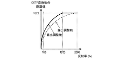
本実施例では、OETF変換部107は、反射率100%の出力値が増加するような露出調整を行い、図3の実線で示す特性で変換された画像データが得られるように、撮像画像データを変換して出力するとする。図3には、露出調整前の特性(図2と同じ)も破線で示されている。図3の例では、露出調整により、反射率100%に対応する出力値が増加するため、反射率100%がより高い表示輝度(表示面の輝度)で表示できるようになる。しかしながら、1200%よりも高い反射率については、出力値が上限値1023に飽和する。このため、OETF変換部107から出力される画像データのダイナミックレンジは、反射率0〜2000%のレンジから反射率0〜1200%のレンジに縮小されてしまう。
In the present embodiment, the
このようなダイナミックレンジの縮小を抑制するなどのために、第1ニー補正部110は第1ニー補正を行う。なお、露出調整が行われた場合でなくても、第1ニー補正は行われることがある。例えば、OETF変換で撮像画像データのダイナミックレンジを拡大する場合などにおいて、第1ニー補正が行われることがある。ニー補正は、輝度の増加に対する階調値の増加の特性がニーポイントの上下で異なるような画像データを得る階調変換である。つまり、第1ニー補正は、輝度の増加に対する階調値の増加の特性が第1ニーポイントの上下で異なるような画像データを得る階調変換である。
The first
本実施例では、図4に示すようなグラフィック画像(OSD(On Screen Display)画像;(GUI(Graphical User Interface)画像)が、撮像装置105の表示部(不図示)に表示される。そして、ユーザは、このグラフィック画像を用いたユーザ操作により、第1ニーポイント入力部109に第1ニーポイントを入力する。本実施例では、第1ニーポイントの反射率(輝度)として以下の値が設定されたとする。
第1ニーポイントの反射率=800%
In this embodiment, a graphic image (OSD (On Screen Display) image; (GUI (Graphical User Interface) image) as shown in FIG. 4 is displayed on the display unit (not shown) of the
1st knee point reflectance = 800%
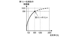
第1ニー補正部110は、OETF変換後の画像データ(OETF変換部107から出力された画像データ)を、第1ニーポイントに基づく第1ニー補正を施して、撮像装置105の外部に出力する。具体的には、図5の破線で示すように、第1ニー補正により、第1ニーポイントよりも高いレンジの特性が、当該レンジの全体で輝度(被写体の反射率)の増加に対して階調値が(指数関数的に)増加するように変更される。図5の実線で示すように、第1ニーポイント以下のレンジの特性は変更されない。
The first
本実施例では、上述した処理により、撮像装置105から、以下のような特性を有する画像データが出力される。
800%以下の反射率のレンジ:
被写体の輝度と第1ニー補正後の輝度(第1ニー補正部110から出力される画像データによって表された輝度)との対応関係が線形特性(リニア特性)である。
800%よりも高い反射率のレンジ:
被写体の輝度と第1ニー補正後の輝度との対応関係は非線形特性(ノンリニア特性)であるが、被写体の輝度の増加に対して第1ニー補正後の輝度も増加する。
In the present embodiment, the above-described processing causes the
Range of reflectance below 800%:
The correspondence between the brightness of the subject and the brightness after the first knee correction (the brightness represented by the image data output from the first knee correction unit 110) is a linear characteristic (linear characteristic).
Range of reflectance higher than 800%:
Although the correspondence between the brightness of the subject and the brightness after the first knee correction is a non-linear characteristic (non-linear property), the brightness after the first knee correction also increases with an increase in the brightness of the subject.
表示装置100について、より詳細に説明する。表示装置100も、「HDR(High Dynamic Range)」などと呼ばれる広いダイナミックレンジに対応した装置である。本実施例では、表示輝度のレンジが0〜1000nitsのレンジであるとする。
The
EOTF変換部101は、入力画像データ(撮像装置105(第1ニー補正部110)から出力され表示装置100に入力された画像データ)を取得する。そして、EOTF変換部101は、入力画像データを、EOTF変換を施して出力する。本実施例では、EOTF変換により、図6に示す対応関係(入力画像データの階調値0〜1023に表示輝度0〜1000nitsが対応付けられた非線形特性(指数関数特性))に従って、撮像画像データの各階調値が変換されるとする(階調変換)。
The
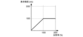
本実施例では、EOTF変換の特性(関数)は、OETF変換の特性(関数)の逆特性(逆関数)に基づくとする。つまり、図6の特性は、図2の特性に基づくとする。このため、EOTF変換後の画像データとして、階調値が被写体の輝度に比例する画像データが得られる(生成される)。つまり、EOTF変換後の画像データを用いれば、図7に示すように、被写体の輝度に比例する表示輝度が実現可能となる。 In the present embodiment, the characteristic (function) of EOTF conversion is based on the inverse characteristic (inverse function) of the characteristic (function) of OETF conversion. That is, the characteristics of FIG. 6 are based on the characteristics of FIG. Therefore, as the image data after the EOTF conversion, image data whose gradation value is proportional to the brightness of the subject is obtained (generated). That is, by using the image data after the EOTF conversion, as shown in FIG. 7, display brightness proportional to the brightness of the subject can be realized.
本実施例では、反射率の単位(%)は表示輝度の単位(nits)に読み替えることができるとする。上述したように、表示輝度のレンジは、0〜1000nitsのレンジであり、撮像画像データや入力画像データのダイナミックレンジ(0〜2000%)よりも狭い。このため、図7に示すように、1000%よりも高い反射率は1000nitsの表示輝度となる(クリップ)。つまり、EOTF変換により、入力画像データのダイナミックレンジが変換(本実施例では圧縮)される(レンジ変換)。具体的には、図6に示すように、反射率1000%に対応する階調値960は、表示輝度1000nitsに対応する階調値に変換される(クリップ)。
In this embodiment, the unit (%) of reflectance can be read as the unit (nits) of display brightness. As described above, the display luminance range is 0 to 1000 nits, which is narrower than the dynamic range (0 to 2000%) of the captured image data or the input image data. Therefore, as shown in FIG. 7, a reflectance higher than 1000% has a display brightness of 1000 nits (clip). That is, the dynamic range of the input image data is converted (compressed in this embodiment) by the EOTF conversion (range conversion). Specifically, as shown in FIG. 6, the
上述したクリップでは、1000%よりも高い複数の反射率に同じ階調値や表示輝度が割り当たるため、高輝度部の階調分布(階調性)が確認できなくなる(階調つぶれ)。このような階調つぶれを抑制するなどのために、第2ニー補正部103は第2ニー補正を行う。なお、クリップが行われた場合でなくても、第2ニー補正は行われることがある。例
えば、EOTF変換で入力画像データのダイナミックレンジを拡張する場合などにおいて、第2ニー補正が行われることがある。
In the above-described clip, the same gradation value and display brightness are assigned to a plurality of reflectances higher than 1000%, so that the gradation distribution (gradation) of the high brightness part cannot be confirmed (gradation collapse). The second
上述したように、第1ニーポイント以下の輝度レンジでは、被写体の輝度と入力画像データによって表された輝度との対応関係は線形特性である。このため、少なくとも第1ニーポイント以下の階調値を、被写体の輝度に対応する(略等しい)表示輝度で表示することが好ましい。第2ニー補正により、第2ニーポイント以下の輝度レンジでは、入力画像データの輝度と表示輝度との対応関係は線形特性となるが、第2ニーポイントよりも高い輝度レンジでは、入力画像データの輝度と表示輝度との対応関係は非線形特性となる。このため、第2ニーポイントの輝度が第1ニーポイントの輝度よりも低いと、第2ニーポイントよりも高く且つ第1ニーポイント以下である階調値を、被写体の輝度に対応する表示輝度で表示できない。 As described above, in the brightness range below the first knee point, the correspondence relationship between the brightness of the subject and the brightness represented by the input image data is a linear characteristic. Therefore, it is preferable to display at least the gradation value equal to or lower than the first knee point with the display brightness corresponding to (substantially equal to) the brightness of the subject. By the second knee correction, the correspondence relationship between the brightness of the input image data and the display brightness has a linear characteristic in the brightness range below the second knee point, but in the brightness range higher than the second knee point, the correspondence of the input image data The correspondence relationship between the brightness and the display brightness has a non-linear characteristic. Therefore, when the luminance of the second knee point is lower than the luminance of the first knee point, the gradation value that is higher than the second knee point and is equal to or lower than the first knee point is set as the display luminance corresponding to the luminance of the subject. Cannot be displayed.
そこで、本実施例では、第2ニーポイント決定部102は、入力情報(撮像装置105(第1ニーポイント入力部109)から出力され表示装置100に入力された情報;第1ニーポイントの情報)を取得する。そして、第2ニーポイント決定部102は、入力情報に基づいて、輝度が第1ニーポイントの輝度以下である第2ニーポイントを決定し出力する。本実施例では、以下に示すように、第2ニーポイントの輝度として、第1ニーポイントの輝度と同じ値が設定されたとする。
第2ニーポイント=800%
=896(入力画像データの階調値)
Therefore, in the present embodiment, the second knee
Second knee point = 800%
= 896 (gradation value of input image data)
なお、第1ニーポイントの情報の取得方法は特に限定されない。ここで、撮像装置105と表示装置100をSDI(Serial Digital Interface)で互いに接続する場合を考える。この場合には、撮像装置105は、第1ニーポイントの情報をSDIのアンシラリ領域に書き込んで画像データと共に出力できる。そして、表示装置100は、撮像装置105から出力された画像データと、アンシラリ領域に書き込まれた情報とを取得することができる。撮像装置105と表示装置100をHDMI(High−Definition Multimedia Interface)で互いに接続する場合にも、同様の処理を行うことができる。
The method of acquiring the first knee point information is not particularly limited. Here, consider a case where the
第2ニー補正部103は、EOTF変換後の画像データ(EOTF変換部101から出力された画像データ)を、第2ニーポイントに基づく第2ニー補正を施して出力する。具体的には、図8,9の破線で示すように、第2ニー補正により、第2ニーポイントよりも高いレンジの特性が、当該レンジの全体で階調値や反射率の増加に対して表示輝度が(指数関数的に)増加するように変更される(特性変換)。図8,9の実線で示すように、第2ニーポイント以下のレンジの特性は変更されない。
The second
本実施例では、上述した処理により、図9に示すように、被写体の輝度と入力画像データによって表された輝度との対応関係が線形特性である輝度範囲(0〜800%)について、被写体の輝度に表示輝度が比例する線形特性を得ることができる。また、他の輝度範囲について、被写体の輝度に表示輝度が増加する非線形特性を得ることができ、階調つぶれを抑制できる。つまり、以下のとおりである。
800%以下の反射率のレンジ:
被写体の輝度と表示輝度との対応関係が線形特性である。
800%よりも高い反射率のレンジ:
被写体の輝度と表示輝度との対応関係は非線形特性であるが、被写体の輝度の増加に
対して表示輝度も増加する。
In the present embodiment, as a result of the above-described processing, as shown in FIG. 9, in the luminance range (0 to 800%) in which the correspondence relationship between the luminance of the subject and the luminance represented by the input image data is a linear characteristic, It is possible to obtain a linear characteristic in which the display brightness is proportional to the brightness. In addition, in other luminance ranges, it is possible to obtain a non-linear characteristic in which the display luminance increases with respect to the luminance of the subject, and it is possible to suppress gradation loss. That is, it is as follows.
Range of reflectance below 800%:
The correspondence between the brightness of the subject and the display brightness is a linear characteristic.
Range of reflectance higher than 800%:
The correspondence between the brightness of the subject and the display brightness is a non-linear characteristic, but the display brightness increases as the brightness of the subject increases.
以上述べたように、本実施例によれば、好適な表示輝度での表示をより確実に実現できる。具体的には、ニー補正が施された画像データをニー補正を施して表示する場合においても、被写体の輝度に対応する表示輝度を好適に実現できる。 As described above, according to this embodiment, it is possible to more reliably realize the display with the suitable display brightness. Specifically, even when the knee-corrected image data is displayed with the knee correction, the display brightness corresponding to the brightness of the subject can be preferably realized.
なお、本実施例では、撮像装置105が第1ニー補正を行い、撮像装置105と表示装置100が互いに接続され、表示装置100が撮像装置105から画像データと第1ニーポイントの情報とを個別に取得する例を説明したが、これに限られない。例えば、第1ニー補正を行う装置は撮像装置105でなくてもよい。また、第1ニーポイントの情報は、第1ニー補正後の画像データにメタデータとして付加されてもよい。この場合には、表示装置100は、第1ニー補正を行う装置とは異なる装置(画像の編集工程で使用される編集装置など)に接続されていても、接続された装置からの画像データに付加されたメタデータを取得することで、第1ニーポイントの情報を取得できる。
In the present embodiment, the
また、表示装置100は、ニー補正が施されていない画像データを取得した場合に、所定のニーポイントを第2ニーポイントとして使用してもよい。第2ニー処理後の画像データのダイナミックレンジは、第2ニー処理前の画像データのダイナミックレンジより狭くても広くてもよい。第2ニー処理後の画像データのダイナミックレンジは、表示輝度のレンジより狭くても広くてもよい。EOTF変換と第2ニー処理とは個別に行われなくてもよい。
In addition, the
また、本実施例では第1ニーポイントが反射率(%)で指定される例を説明したが(図4)、第1ニーポイントは、階調値(0〜1023;図3に示す露出調整後の階調値)で指定されてもよいし、輝度(nits)で指定されてもよい。同様に、第1ニーポイントの情報は、反射率を示す情報であってもよいし、階調値を示す情報であってもよいし、輝度を示す情報であってもよい。第1ニーポイントの情報は、それら3つの情報のうちの2つ以上を含んでいてもよい。 In addition, although the example in which the first knee point is designated by the reflectance (%) is described in the present embodiment (FIG. 4), the first knee point is the gradation value (0 to 1023; the exposure adjustment shown in FIG. 3). The gradation value may be specified later, or the brightness (nits) may be specified. Similarly, the information of the first knee point may be information indicating the reflectance, information indicating the gradation value, or information indicating the brightness. The information of the first knee point may include two or more of the three pieces of information.
第1ニーポイントの輝度(nits)は、図3に示す露出調整後の階調値から、図6に示すようなEOTF変換の関数(特性)を用いて算出できる。但し、EOTF変換の関数として、クリップをしない関数を使用する。第1ニーポイントの輝度(nits)は、他の方法でも算出できる。例えば、撮像装置105で設定された露出設定値(反射率100%と輝度(nits)の関係)を表示装置100に送信する。表示装置100は、露出設定値から図7に示すような関数(特性)を判断し、判断した関数を用いて第1ニーポイントの反射率(%)から輝度(nits)を算出できる。但し、関数として、クリップをしない関数を使用する。撮像装置105の露出基準値(露出設定値の基準値)に基づいて、第1ニーポイントの反射率(%)を絶対輝度に変換できる。
The brightness (nits) at the first knee point can be calculated from the gradation value after exposure adjustment shown in FIG. 3 using a function (characteristic) of EOTF conversion as shown in FIG. However, a function that does not clip is used as a function of EOTF conversion. The brightness (nits) of the first knee point can be calculated by other methods. For example, the exposure setting value (relationship between 100% reflectance and luminance (nits)) set by the
<実施例2>
以下、本発明の実施例2について説明する。実施例1では、第1ニーポイントの輝度が表示輝度の上限(第2ニー処理後の画像データの輝度の上限)以下である例として説明した。実施例2では、第1ニーポイントの輝度が表示輝度の上限よりも高い場合の例を説明する。なお、以下では、実施例1と異なる点(構成、処理、等)について詳しく説明し、実施例1と同じ点についての説明は省略する。
<Example 2>
Example 2 of the present invention will be described below. In the first embodiment, the luminance at the first knee point is equal to or lower than the upper limit of the display luminance (the upper limit of the luminance of the image data after the second knee processing). In the second embodiment, an example in which the brightness of the first knee point is higher than the upper limit of the display brightness will be described. In the following, points (configuration, processing, etc.) different from the first embodiment will be described in detail, and description of the same points as the first embodiment will be omitted.
図10は、本実施例に係る表示システムの構成例を示すブロック図である。図10において、図1(実施例1)と同じブロックには図1と同じ符号が付されている。 FIG. 10 is a block diagram showing a configuration example of the display system according to the present embodiment. 10, the same blocks as those in FIG. 1 (Embodiment 1) are designated by the same reference numerals as those in FIG.
表示装置200において、EOTF変換部201は、図1のEOTF変換部101と同様の機能を有する。但し、EOTF変換部201は、第1ニーポイントの情報を撮像装置105から取得する。そして、EOTF変換部201は、第1ニーポイントの輝度が表示輝度の上限よりも高い場合に、第1ニーポイントに基づいて画像データ(入力画像データ)のダイナミックレンジを変換する。これにより、特定の輝度レンジにおいて輝度(表示輝度)が入力画像データの輝度(被写体の輝度)に比例(略比例)する画像データが生成される。
In the
本実施例では、第1ニーポイントの輝度が800%(800nits)であり、表示輝度の上限が500nitsであるとする。そして、EOTF変換部201は、1000nits以下の輝度レンジを特定の輝度レンジとして用いるとする。このため、図11に示すように、入力画像データのダイナミックレンジが、0〜1000%の輝度レンジから0〜500nitsの輝度レンジに圧縮される。
In the present embodiment, it is assumed that the brightness of the first knee point is 800% (800 nits) and the upper limit of the display brightness is 500 nits. Then, the
これにより、画像の表示輝度が全体的に低下するが、反射率の変化に対する表示輝度の変化の線形性を保つことができる。なお、特定の輝度レンジにおける表示輝度の下限は、1000%に限られず、第2のニーポイントの輝度以上の輝度であればよい。また、ダイナミックレンジの圧縮方法は特に限定されない。例えば、圧縮方法として、従来提案された様々な方法(特開2016−173477号公報に記載の方法など)を使用できる。 As a result, the display brightness of the image is reduced as a whole, but the linearity of the change in the display brightness with respect to the change in the reflectance can be maintained. The lower limit of the display brightness in the specific brightness range is not limited to 1000%, and may be a brightness equal to or higher than the brightness of the second knee point. Further, the dynamic range compression method is not particularly limited. For example, various conventionally proposed methods (such as the method described in JP-A-2016-173477) can be used as the compression method.
そして、EOTF変換部201から出力された画像データは、第2ニー補正部103で第2ニー補正が施されて表示部104で表示される。第2ニーポイントの輝度を800%として第2ニー補正を行うことにより、図11の特性は図12の特性に変換される。
Then, the image data output from the
以上述べたように、本実施例によれば、第1ニーポイントの輝度が表示輝度の上限(第2ニー処理後の画像データの輝度の上限)より高い場合であっても、好適な表示輝度での表示を実現できる。具体的には、第1ニーポイントの輝度以下の輝度レンジにおいて、被写体の輝度よりは低いが被写体の輝度に比例する表示輝度を実現できる。 As described above, according to the present embodiment, even when the brightness of the first knee point is higher than the upper limit of the display brightness (the upper limit of the brightness of the image data after the second knee processing), the preferable display brightness is obtained. The display in can be realized. Specifically, in the luminance range equal to or lower than the luminance of the first knee point, display luminance lower than the luminance of the subject but proportional to the luminance of the subject can be realized.
<実施例3>
以下、本発明の実施例3について説明する。実施例1では、第1のニーポイントに基づいて第2のニーポイントが自動で決定されて設定される例を説明した。本実施例では、第2のニーポイントを指定するユーザ操作に応じて第2のニーポイントが設定される例を説明する。なお、以下では、実施例1と異なる点(構成、処理、等)について詳しく説明し、実施例1と同じ点についての説明は省略する。
<Example 3>
Example 3 of the present invention will be described below. In the first embodiment, the example in which the second knee point is automatically determined and set based on the first knee point has been described. In the present embodiment, an example will be described in which the second knee point is set according to a user operation of designating the second knee point. In the following, points (configuration, processing, etc.) different from the first embodiment will be described in detail, and description of the same points as the first embodiment will be omitted.
図13は、本実施例に係る表示システムの構成例を示すブロック図である。本発明の第3の実施形態が適用できるブロック図である。図13において、図1(実施例1)と同じブロックには図1と同じ符号が付されている。表示装置300は、図1の第2ニーポイント決定部102の代わりに、第2ニーポイント下限決定部301と第2ニーポイント入力部302を有する。
FIG. 13 is a block diagram showing a configuration example of the display system according to the present embodiment. It is a block diagram which can apply the 3rd Embodiment of this invention. 13, the same blocks as in FIG. 1 (Embodiment 1) are assigned the same reference numerals as in FIG. The
第2ニーポイント下限決定部301は、入力情報(撮像装置105(第1ニーポイント入力部109)から出力され表示装置100に入力された情報;第1ニーポイントの情報)を取得する。そして、第2ニーポイント下限決定部301は、入力情報に基づいて第1ニーポイント(第1ニーポイントの輝度)を、第2ニーポイント(第2ニーポイントの輝度)の下限として第2ニーポイント入力部302に通知する。
The second knee point lower
第2ニーポイント入力部302は、第2ニーポイント下限決定部301からの通知に基づいて、第1ニーポイントが第2ニーポイントの下限となるように、第2ニーポイントを
指定するユーザ操作を受け付ける。そして、第2ニーポイント入力部302は、ユーザ操作によって応じた第2ニーポイント(ユーザ操作によって指定された第2ニーポイント)を、第2ニー補正部103に出力して設定する。
The second knee
本実施例では、第1ニーポイントの輝度が800%(800nits)であるとする。このため、図14に示すようなグラフィック画像(OSD(On Screen Display)画像;(GUI(Graphical User Interface)画像)が、表示部104に表示される。そして、ユーザは、このグラフィック画像を用いたユーザ操作により、第2ニーポイント入力部302に第2ニーポイントを入力する。図14のグラフィック画像では、800nits(第1ニーポイントの輝度)が第2ニーポイントの輝度の下限として示されている。ユーザは、800nits以上の輝度を第2ニーポイントの輝度として指定でき、800nits未満の輝度を第2ニーポイントの輝度として指定できない。
In the present embodiment, the brightness at the first knee point is 800% (800 nits). For this reason, a graphic image (OSD (On Screen Display) image; (GUI (Graphical User Interface) image) as shown in Fig. 14 is displayed on the
以上述べたように、本実施例によれば、第1ニーポイントの輝度以上の輝度を第2ニーポイントの輝度としてユーザが指定できる。これにより、より好適な表示輝度での表示をより確実に実現できる。 As described above, according to this embodiment, the user can specify the brightness equal to or higher than the brightness of the first knee point as the brightness of the second knee point. Accordingly, it is possible to more reliably realize display with more suitable display brightness.
なお、第1ニーポイントの決定前に、ユーザ操作に応じて任意の第2ニーポイントが設定されてもよい。そして、表示装置300は、第2ニーポイントの輝度が第1ニーポイントの輝度の上限となるように、第2ニーポイントの輝度に関する情報を表示装置300の外部に出力してもよい。この場合には、撮像装置105は、図15に示すようなグラフィック画像を表示部(不図示)に表示する。そして、ユーザは、このグラフィック画像を用いたユーザ操作により、第1ニーポイント入力部109に第1ニーポイントを入力する。
In addition, before determining the first knee point, an arbitrary second knee point may be set according to a user operation. Then, the
図15は、第2ニーポイントの輝度が800nits(800%)である場合の例を示す。図15のグラフィック画像では、800nits(第2ニーポイントの輝度)が第1ニーポイントの輝度の上限として示されている。ユーザは、800nits以下の輝度を第1ニーポイントの輝度として指定でき、800nitsよりも高い輝度を第1ニーポイントの輝度として指定できない。 FIG. 15 shows an example in which the brightness at the second knee point is 800 nits (800%). In the graphic image of FIG. 15, 800 nits (luminance at the second knee point) is shown as the upper limit of the luminance at the first knee point. The user can specify the brightness of 800 nits or less as the brightness of the first knee point, and cannot specify the brightness higher than 800 nits as the brightness of the first knee point.
また、本実施例では第2ニーポイントが輝度(nits)で指定される例を説明したが(図14)、第2ニーポイントは、階調値で指定されてもよいし、反射率(%)で指定されてもよい。同様に、第2ニーポイントの情報は、反射率を示す情報であってもよいし、階調値を示す情報であってもよいし、輝度を示す情報であってもよい。第2ニーポイントの情報は、それら3つの情報のうちの2つ以上を含んでいてもよい。 In addition, although the example in which the second knee point is designated by the brightness (nits) has been described in the present embodiment (FIG. 14), the second knee point may be designated by the gradation value or the reflectance (%). ) May be specified. Similarly, the information of the second knee point may be information indicating the reflectance, information indicating the gradation value, or information indicating the brightness. The information of the second knee point may include two or more of the three pieces of information.
なお、実施例1〜3(図1,10,13)の各ブロックは、個別のハードウェアであってもよいし、そうでなくてもよい。2つ以上のブロックの機能が、共通のハードウェアによって実現されてもよい。1つのブロックの複数の機能のそれぞれが、個別のハードウェアによって実現されてもよい。1つのブロックの2つ以上の機能が、共通のハードウェアによって実現されてもよい。また、各ブロックは、ハードウェアによって実現されてもよいし、そうでなくてもよい。例えば、装置が、プロセッサと、制御プログラムが格納されたメモリとを有していてもよい。そして、装置が有する少なくとも一部のブロックの機能が、プロセッサがメモリから制御プログラムを読み出して実行することにより実現されてもよい。 Each block of the first to third embodiments (FIGS. 1, 10, and 13) may or may not be individual hardware. The functions of two or more blocks may be implemented by common hardware. Each of the plurality of functions of one block may be realized by individual hardware. Two or more functions of one block may be implemented by common hardware. Also, each block may or may not be realized by hardware. For example, the device may have a processor and a memory in which a control program is stored. The functions of at least some of the blocks of the device may be realized by the processor reading the control program from the memory and executing the control program.
なお、実施例1〜3(上述した変形例を含む)はあくまで一例であり、本発明の要旨の範囲内で実施例1〜3の構成を適宜変形したり変更したりすることにより得られる構成も、本発明に含まれる。実施例1〜3の構成を適宜組み合わせて得られる構成も、本発明に
含まれる。
It should be noted that Embodiments 1 to 3 (including the modifications described above) are merely examples, and configurations obtained by appropriately modifying or changing the configurations of Embodiments 1 to 3 within the scope of the gist of the present invention. Are also included in the present invention. The present invention also includes configurations obtained by appropriately combining the configurations of the first to third embodiments.
<その他の実施例>
本発明は、上述の実施例の1以上の機能を実現するプログラムを、ネットワーク又は記憶媒体を介してシステム又は装置に供給し、そのシステム又は装置のコンピュータにおける1つ以上のプロセッサがプログラムを読出し実行する処理でも実現可能である。また、1以上の機能を実現する回路(例えば、ASIC)によっても実現可能である。
<Other Examples>
The present invention supplies a program that implements one or more functions of the above-described embodiments to a system or apparatus via a network or a storage medium, and one or more processors in a computer of the system or apparatus read and execute the program. It can also be realized by the processing. It can also be realized by a circuit (for example, ASIC) that realizes one or more functions.
100,200,300:表示装置 101,201:EOTF変換部
102:第2ニーポイント決定部 103:第2ニー補正部 104:表示部
301:第2ニーポイント下限決定部 302:第2ニーポイント入力部
100, 200, 300:
Claims (11)
第2の輝度に基づいて、輝度の増加に対する階調値の増加の特性が前記第2の輝度の上下で異なるような第2の画像データに、前記第1の画像データを変換する変換手段と、
前記第2の画像データに基づいて画像を表示する表示手段と、
を有し、
前記第2の輝度は、前記第1の輝度以上である
ことを特徴とする表示装置。 An acquisition unit that acquires the first image data in which the characteristic of the increase of the gradation value with respect to the increase of the brightness is changed so that it is different at the upper and lower sides of the first brightness;
Conversion means for converting the first image data into second image data such that the characteristic of the increase of the gradation value with respect to the increase of the brightness is different above and below the second brightness based on the second brightness. ,
Display means for displaying an image based on the second image data;
Have
The display device, wherein the second brightness is equal to or higher than the first brightness.
前記第1の輝度は、前記第1の画像データを得るためのニー補正におけるニーポイントに対応し、
前記第2の輝度は、前記第2の画像データを得るためのニー補正におけるニーポイントに対応する
ことを特徴とする請求項1に記載の表示装置。 Each of the first image data and the second image data is image data subjected to knee correction,
The first brightness corresponds to a knee point in knee correction for obtaining the first image data,
The display device according to claim 1, wherein the second brightness corresponds to a knee point in knee correction for obtaining the second image data.
ことを特徴とする請求項1〜3のいずれか1項に記載の表示装置。 The display device according to claim 1, wherein the luminance range of the second image data is equal to the display luminance range.
前記第1の画像データの輝度レンジを変換して、前記第2の輝度以上の輝度である第3の輝度以下の輝度レンジにおいて輝度が前記第1の画像データの輝度に略比例する第3の画像データを生成するレンジ変換手段と、
前記第2の輝度に基づいて、前記第2の輝度以上の輝度レンジにおける前記第3の画像データの特性を変換して前記第2の画像データを生成する特性変換手段と、
を有する
ことを特徴とする請求項1〜4のいずれか1項に記載の表示装置。 The conversion means is
A luminance range of the first image data is converted so that the luminance is substantially proportional to the luminance of the first image data in a luminance range of the third luminance or less which is the luminance of the second luminance or more. Range conversion means for generating image data,
A characteristic conversion means for converting the characteristic of the third image data in the luminance range equal to or higher than the second luminance to generate the second image data based on the second luminance;
The display device according to any one of claims 1 to 4, further comprising:
前記情報に基づいて前記第2の輝度を設定する設定手段と、
をさらに有する
ことを特徴とする請求項1〜5のいずれか1項に記載の表示装置。 An acquisition unit that acquires information about the first brightness;
Setting means for setting the second brightness based on the information;
The display device according to any one of claims 1 to 5, further comprising:
ことを特徴とする請求項6に記載の表示装置。 The display device according to claim 6, wherein the setting unit automatically sets the second brightness based on the information.
前記情報に基づいて、前記第1の輝度が前記第2の輝度の下限となるように、前記第2の輝度を指定するユーザ操作を受け付け、
前記ユーザ操作によって指定された前記第2の輝度を設定する
ことを特徴とする請求項6に記載の表示装置。 The setting means,
Accepting a user operation for designating the second brightness so that the first brightness is the lower limit of the second brightness based on the information;
The display device according to claim 6, wherein the second brightness designated by the user operation is set.
前記第2の輝度が第1の輝度の上限となるように、前記第2の輝度に関する情報を前記
表示装置の外部に出力する出力手段と、
をさらに有する
ことを特徴とする請求項1〜5のいずれか1項に記載の表示装置。 Setting means for setting the second brightness according to a user operation;
Output means for outputting information about the second brightness to the outside of the display device so that the second brightness is the upper limit of the first brightness;
The display device according to any one of claims 1 to 5, further comprising:
第2の輝度に基づいて、輝度の増加に対する階調値の増加の特性が前記第2の輝度の上下で異なるような第2の画像データに、前記第1の画像データを変換するステップと、
前記第2の画像データに基づいて画像を表示するステップと、
を有し、
前記第2の輝度は、前記第1の輝度以上である
ことを特徴とする表示方法。 A step of obtaining first image data in which the characteristic of the increase of the gradation value with respect to the increase of the brightness is changed so as to be different above and below the first brightness;
Converting the first image data into second image data in which the characteristic of the increase in the gradation value with respect to the increase in the brightness is different between above and below the second brightness based on the second brightness;
Displaying an image based on the second image data;
Have
The display method, wherein the second brightness is equal to or higher than the first brightness.
Priority Applications (2)
| Application Number | Priority Date | Filing Date | Title |
|---|---|---|---|
| JP2018194207A JP2020064102A (en) | 2018-10-15 | 2018-10-15 | Display unit and display method |
| US16/599,233 US11037527B2 (en) | 2018-10-15 | 2019-10-11 | Display apparatus and display method |
Applications Claiming Priority (1)
| Application Number | Priority Date | Filing Date | Title |
|---|---|---|---|
| JP2018194207A JP2020064102A (en) | 2018-10-15 | 2018-10-15 | Display unit and display method |
Publications (2)
| Publication Number | Publication Date |
|---|---|
| JP2020064102A true JP2020064102A (en) | 2020-04-23 |
| JP2020064102A5 JP2020064102A5 (en) | 2021-11-18 |
Family
ID=70161439
Family Applications (1)
| Application Number | Title | Priority Date | Filing Date |
|---|---|---|---|
| JP2018194207A Withdrawn JP2020064102A (en) | 2018-10-15 | 2018-10-15 | Display unit and display method |
Country Status (2)
| Country | Link |
|---|---|
| US (1) | US11037527B2 (en) |
| JP (1) | JP2020064102A (en) |
Family Cites Families (11)
| Publication number | Priority date | Publication date | Assignee | Title |
|---|---|---|---|---|
| KR100617781B1 (en) * | 2004-06-29 | 2006-08-28 | 삼성전자주식회사 | Apparatus and method for improving image quality in a image sensor |
| JP4131280B2 (en) | 2006-04-20 | 2008-08-13 | ソニー株式会社 | Imaging apparatus and video signal processing method |
| JP5211521B2 (en) * | 2007-03-26 | 2013-06-12 | 株式会社ニコン | Image processing apparatus, image processing method, image processing program, and camera |
| JP6202330B2 (en) * | 2013-10-15 | 2017-09-27 | ソニー株式会社 | Decoding device and decoding method, and encoding device and encoding method |
| CN106464966B (en) * | 2014-05-12 | 2020-12-08 | 索尼公司 | Communication apparatus, communication method, and computer-readable storage medium |
| JP6552228B2 (en) | 2015-03-17 | 2019-07-31 | キヤノン株式会社 | Image display apparatus and control method thereof |
| JP6700880B2 (en) * | 2016-03-17 | 2020-05-27 | キヤノン株式会社 | Information processing apparatus and information processing method |
| EP3511928B1 (en) | 2016-09-09 | 2022-01-12 | Panasonic Intellectual Property Management Co., Ltd. | Display device and signal processing method |
| JP2018042198A (en) * | 2016-09-09 | 2018-03-15 | オリンパス株式会社 | Imaging apparatus and imaging method |
| JP7054851B2 (en) | 2016-09-09 | 2022-04-15 | パナソニックIpマネジメント株式会社 | Display device and signal processing method |
| US10726315B2 (en) * | 2016-11-17 | 2020-07-28 | Panasonic Intellectual Property Management Co., Ltd. | Image processing device, image processing method, and program |
-
2018
- 2018-10-15 JP JP2018194207A patent/JP2020064102A/en not_active Withdrawn
-
2019
- 2019-10-11 US US16/599,233 patent/US11037527B2/en active Active
Also Published As
| Publication number | Publication date |
|---|---|
| US20200118523A1 (en) | 2020-04-16 |
| US11037527B2 (en) | 2021-06-15 |
Similar Documents
| Publication | Publication Date | Title |
|---|---|---|
| JP5991502B2 (en) | Conversion method and conversion device | |
| JP2016213809A (en) | Display method and display device | |
| JP6700880B2 (en) | Information processing apparatus and information processing method | |
| CN102045506A (en) | Image processing apparatus and image processing method | |
| WO2021148057A1 (en) | Method and apparatus for generating low bit width hdr image, storage medium, and terminal | |
| JP6552228B2 (en) | Image display apparatus and control method thereof | |
| JP7020417B2 (en) | Video signal processing device, video signal processing method and video signal processing system | |
| JP2011119868A (en) | Image processing apparatus, and image processing method | |
| JP2017085481A (en) | Video processing device, video processing method, and video processing program | |
| JP2018160777A (en) | Imaging device and control method thereof, program, and storage medium | |
| JP2018017931A (en) | Image processing device, control method thereof, and display device | |
| JP5732175B2 (en) | Image file generation device and display device | |
| JP2008263313A (en) | Image processing apparatus and image processing program | |
| JP6210772B2 (en) | Information processing apparatus, imaging apparatus, control method, and program | |
| JP2019080156A (en) | Image processing method and image processing apparatus | |
| JP2020064102A (en) | Display unit and display method | |
| US10121265B2 (en) | Image processing device and method to calculate luminosity of an environmental light of an image | |
| JP2017182702A (en) | Image processing device, control method thereof, and program | |
| JP6948173B2 (en) | Image processing equipment and methods, imaging equipment, and imaging systems | |
| JP6628925B2 (en) | Image display device and control method thereof | |
| JP2019149106A (en) | Image processor, image processing method, and program | |
| JP7332325B2 (en) | IMAGE PROCESSING DEVICE, IMAGING DEVICE, IMAGE PROCESSING METHOD, AND PROGRAM | |
| JP2018136482A (en) | Image processing device and image processing method | |
| JP2020060626A (en) | Image processing apparatus and image processing method | |
| JP2021048522A (en) | Image processing apparatus and image processing method |
Legal Events
| Date | Code | Title | Description |
|---|---|---|---|
| A521 | Request for written amendment filed |
Free format text: JAPANESE INTERMEDIATE CODE: A523 Effective date: 20211008 |
|
| A621 | Written request for application examination |
Free format text: JAPANESE INTERMEDIATE CODE: A621 Effective date: 20211008 |
|
| A761 | Written withdrawal of application |
Free format text: JAPANESE INTERMEDIATE CODE: A761 Effective date: 20211125 |