JP2020062841A - Three-dimensional modeling apparatus and three-dimensional modeling method - Google Patents
Three-dimensional modeling apparatus and three-dimensional modeling method Download PDFInfo
- Publication number
- JP2020062841A JP2020062841A JP2018196933A JP2018196933A JP2020062841A JP 2020062841 A JP2020062841 A JP 2020062841A JP 2018196933 A JP2018196933 A JP 2018196933A JP 2018196933 A JP2018196933 A JP 2018196933A JP 2020062841 A JP2020062841 A JP 2020062841A
- Authority
- JP
- Japan
- Prior art keywords
- photocurable resin
- base
- liquid photocurable
- transmission window
- layer
- Prior art date
- Legal status (The legal status is an assumption and is not a legal conclusion. Google has not performed a legal analysis and makes no representation as to the accuracy of the status listed.)
- Pending
Links
Images


Abstract
Description
本発明は、光硬化性樹脂を硬化させて三次元物体を造形する三次元造形装置および三次元造形方法に関する。 The present invention relates to a three-dimensional modeling apparatus and a three-dimensional modeling method for curing a photocurable resin to model a three-dimensional object.
近年、いわゆる3Dプリンタの開発が盛んに行われており、例えば、光硬化性樹脂を用いた光造形法、熱溶融積層造形法、粉末積層溶融法等のさまざまな方式が知られている。
光硬化性樹脂を用いた光造形法は、液体状光硬化性樹脂に例えば紫外線を照射して樹脂を硬化させ、基台上に積層してゆくことにより三次元造形物を形成する方法である。造形しようとする物の形状データに基づいて硬化光の照射パターンを制御しながら積層して造形することにより、微細な形状の三次元造形物を高精度に形成できる長所がある。光造形法は、液体状光硬化性樹脂の供給方法により、自由液面方式と規制液面方式に大別される。
In recent years, so-called 3D printers have been actively developed, and various methods such as a stereolithography method using a photocurable resin, a hot-melt laminating method, and a powder laminating / melting method are known.
The stereolithography method using a photocurable resin is a method of forming a three-dimensional model by irradiating a liquid photocurable resin with, for example, ultraviolet rays to cure the resin and stacking the resin on a base. . There is an advantage that a three-dimensional molded object having a fine shape can be formed with high accuracy by stacking and modeling while controlling the irradiation pattern of the curing light based on the shape data of the object to be molded. The stereolithography method is roughly classified into a free liquid level method and a regulated liquid level method, depending on the liquid photocurable resin supply method.
自由液面方式では、容器に貯留した液体状光硬化性樹脂の中に基台を浸漬させておき、蓋や窓により規制されてはいない自由液面を通して硬化光を照射して、基台上に造形物を形成してゆく。一層の硬化が完了したら、硬化層の上に次の層を形成するための液体状光硬化性樹脂を供給する必要があるが、樹脂の供給と自由液面の平滑化(揺れの沈静)が完了するまでは、次の硬化光の照射を待つ必要がある。 In the free liquid level method, the base is immersed in the liquid photocurable resin stored in the container, and the curing light is irradiated through the free liquid surface that is not regulated by the lid or window, Form a molded object on. When the curing of one layer is completed, it is necessary to supply the liquid photo-curable resin for forming the next layer on the cured layer, but the supply of the resin and the smoothing of the free liquid surface (settling of shaking) It is necessary to wait for the next irradiation of curing light until the completion.
一方、規制液面方式では、液体状光硬化性樹脂を貯留した容器の液位内に光透過窓を設けておき、液面を規制している光透過窓を通して硬化光を照射して、基台上に造形物を形成してゆく。一層の硬化が完了したら、次の層を形成するための液体状光硬化性樹脂を供給する必要があるが、光透過窓から基台を離間させて生ずる空間に液体状光硬化性樹脂の充填が完了するまでは、次の硬化光の照射を待つ必要がある。ただし、自由液面方式とは異なり、充填が完了しさえすれば、自由液面の平滑化(揺れの沈静)を待つ必要は無い。 On the other hand, in the regulated liquid level method, a light transmission window is provided in the liquid level of the container that stores the liquid photocurable resin, and curing light is irradiated through the light transmission window that regulates the liquid level, Formed objects on the table. When curing of one layer is completed, it is necessary to supply liquid photocurable resin to form the next layer, but the space created by separating the base from the light transmission window is filled with liquid photocurable resin. It is necessary to wait for the next irradiation of the curing light until the above is completed. However, unlike the free liquid level method, it is not necessary to wait for the smoothing of the free liquid surface (settling of shaking) as long as the filling is completed.
特許文献1に記載された規制液面方式では、一層の硬化が完了したら、基台上に形成された硬化層を光透過窓から分離するために基台を光透過窓から離間させる。その際には、硬化層一層の厚み分よりも大きな距離だけ基台を光透過窓から離間させ、硬化層と光透過窓の間に液体状光硬化性樹脂を供給する。そして、供給を完了させてから、次の硬化層を形成するのに適した液体状光硬化性樹脂の厚みになるまで基台を光透過窓に接近させ、その後に次の硬化光を照射していた。すなわち、一層の硬化が完了した後、適度な厚さの液体状光硬化性樹脂を供給するために、基台を昇降させていた。
In the regulated liquid level method described in
また、特許文献2に記載された規制液面方式では、一層の硬化を行う毎に基台を昇降動作するのではなく、基台を連続的に引上げながら光造形を行っている。光硬化性樹脂の硬化を阻害する物質として例えば酸素が知られているが、特許文献2の装置では、酸素を透過する材料で光透過窓を構成して、光透過窓の内面近傍に光硬化性樹脂の硬化を阻害する硬化阻害領域を形成している。光透過窓を透過する酸素により硬化阻害領域が常に形成されるため、液状光硬化性樹脂の流路を確保することが可能となり、基台を引上げながら液状光硬化性樹脂を供給して、連続的に光造形を行うことができる。
Further, in the regulated liquid level method described in
光造形法は、微細な形状の三次元造形物を高精度に形成できる長所があるが、産業上の利用価値を高めるには、造形に要する時間を短縮して製造のスループットを向上させることが重要である。特に液体状光硬化性樹脂として高粘度の材料を用いる場合には、低粘度の材料を用いる場合に比べて造形領域に液体状光硬化性樹脂を供給するのに要する時間が長くなり、製造のスループットが低下してしまう。しかし、最近では、機械的特性や熱的特性を向上するため、液体状光硬化性樹脂にフィラーなどの添加物を加える場合があり、高粘度の造形材料が用いられる傾向にある。 The stereolithography method has an advantage that a three-dimensional object with a fine shape can be formed with high precision, but in order to increase the industrial utility value, it is necessary to shorten the time required for modeling and improve the manufacturing throughput. is important. In particular, when a high-viscosity material is used as the liquid photo-curable resin, the time required to supply the liquid photo-curable resin to the modeling area is longer than that when a low-viscosity material is used, and Throughput decreases. However, recently, in order to improve mechanical properties and thermal properties, an additive such as a filler may be added to the liquid photocurable resin, and a high-viscosity modeling material tends to be used.
特許文献1や特許文献2のような規制液面方式では、高粘度の液体状光硬化性樹脂の供給を速くするためには、基台の移動速度を高速化して樹脂の流動を速くすることが考えられる。しかし、単純に基台の移動速度を高速化するだけでは、基台上の三次元造形物に過大な力がかかり、三次元造形物の変形や破損、基台からの脱落を生じる場合があり、製造歩留まりが低下してしまう。
そのため、高粘度の液体状光硬化性樹脂でも、三次元造形物に過大な力をかけることなく、造形領域に高速に液体状光硬化性樹脂を供給可能な技術が求められていた。
In the regulated liquid level method as disclosed in
Therefore, even with a highly viscous liquid photocurable resin, there has been a demand for a technique capable of supplying the liquid photocurable resin at high speed to the modeling area without applying an excessive force to the three-dimensional structure.
本発明は、液状光硬化性樹脂を貯留可能で、光透過窓を有する容器と、基台と、光源と、を備え、前記光源から前記光透過窓を通して前記液状光硬化性樹脂に硬化光を照射して硬化層を形成することを繰り返して、前記基台に複数の硬化層を積層して三次元造形物を形成するが、一の硬化層の形成を終了した後に、次に形成する硬化層の原料となる前記液状光硬化性樹脂を前記一の硬化層と前記透過窓の間に供給するため前記基台を前記光透過窓から離間する方向に移動させるが、供給する時に前記液状光硬化性樹脂が前記一の硬化層の端部から内側に向けて流動する最大距離をLとした時、前記一の硬化層の形状がLの大きな形状であるほど、前記基台を前記光透過窓から離間する方向に移動させる移動速度Vを小さくする、ことを特徴とする三次元造形装置である。 The present invention is capable of storing a liquid photocurable resin, comprises a container having a light transmission window, a base, and a light source, and cure light from the light source to the liquid photocurable resin through the light transmission window. By repeating irradiation to form a hardened layer, a plurality of hardened layers are laminated on the base to form a three-dimensional structure, but after the formation of one hardened layer is completed, the hardening to be formed next In order to supply the liquid photocurable resin, which is a raw material of the layer, between the one cured layer and the transmission window, the base is moved in a direction away from the light transmission window. When the maximum distance that the curable resin flows from the end of the one cured layer toward the inside is L, the larger the shape of the one cured layer is, the larger the shape of L is. The moving speed V for moving in the direction away from the window is reduced. That is a three-dimensional modeling apparatus.
また、本発明は、液状光硬化性樹脂を貯留可能で、光透過窓を有する容器と、基台と、光源と、を備えた三次元造形装置を用い、前記光源から前記光透過窓を通して前記液状光硬化性樹脂に硬化光を照射して硬化層を形成することを繰り返して、前記基台に複数の硬化層を積層して三次元造形物を形成する三次元造形方法において、一の硬化層の形成を終了した後に、次に形成する硬化層の原料となる前記液状光硬化性樹脂を前記一の硬化層と前記透過窓の間に供給するため前記基台を前記光透過窓から離間する方向に移動させるが、供給する時に前記液状光硬化性樹脂が前記一の硬化層の端部から内側に向けて流動する最大距離をLとした時、前記一の硬化層の形状がLの大きな形状であるほど、前記基台を前記光透過窓から離間する方向に移動させる移動速度Vを小さくする、ことを特徴とする三次元造形方法である。 Further, the present invention is capable of storing a liquid photocurable resin, using a three-dimensional modeling apparatus provided with a container having a light transmission window, a base, and a light source, from the light source through the light transmission window, In the three-dimensional modeling method in which the liquid photocurable resin is repeatedly irradiated with curing light to form a cured layer, and a plurality of cured layers are laminated on the base to form a three-dimensional model, one curing After the formation of the layer is completed, the base is separated from the light transmission window in order to supply the liquid photocurable resin, which is a raw material of the next cured layer, between the one curing layer and the transmission window. When the liquid photocurable resin is supplied, the shape of the one cured layer is L when the maximum distance that the liquid photocurable resin flows inward from the end of the one cured layer is L. The larger the shape, the direction in which the base is separated from the light transmission window. To reduce the moving speed V which moved a 3D modeling method characterized by.
本発明は、高粘度の液体状光硬化性樹脂でも、三次元造形物に過大な力をかけることなく、造形領域に高速に液体状光硬化性樹脂を供給可能な技術を提供する。 The present invention provides a technique capable of supplying a liquid photocurable resin to a modeling region at high speed without applying an excessive force to a three-dimensional model even with a highly viscous liquid photocurable resin.
[実施形態1]
以下、図面を参照して、本発明の実施形態1である三次元造形物の製造方法と三次元造形装置について説明する。以下の説明では、特段のただし書きがない限り、硬化していない液状の光硬化性樹脂を液状光硬化性樹脂と記す。また、液状光硬化性樹脂を光硬化させて形成した造形物を、三次元造形物あるいは単に造形物と記す。尚、三次元造形物とは形成すべき複数の硬化層を全て積層した完成品に限らず、途中の層まで形成した段階における半完成品も含むものとする。
[Embodiment 1]
Hereinafter, a method of manufacturing a three-dimensional structure and a three-dimensional structure forming apparatus according to a first embodiment of the present invention will be described with reference to the drawings. In the following description, an uncured liquid photo-curable resin is referred to as a liquid photo-curable resin unless otherwise specified. Further, a modeled product formed by photocuring a liquid photocurable resin is referred to as a three-dimensional modeled product or simply a modeled product. The three-dimensional model is not limited to a finished product in which a plurality of hardened layers to be formed are all laminated, but includes a semi-finished product at a stage where intermediate layers are formed.
[光硬化性樹脂]
本発明の実施に用いる液状光硬化性樹脂は、少なくとも重合性化合物を含み、その他、樹脂材料や、重合開始剤、重合禁止剤、酸化防止剤、耐熱安定剤、耐光安定剤、離型剤等の各種添加剤を含んでいてもよい。
本発明の実施に用いる重合性化合物としては、特に制限は無く、例えば、アクリル化合物、メタクリル化合物、ビニル化合物等が挙げられるがこれらに限定されない。
また、前記樹脂材料は、例えば、アクリル樹脂、メタクリル樹脂、ポリオレフィン樹脂、ポリエステル樹脂、ポリアミド樹脂、ポリカーボネート樹脂、ポリイミド樹脂等が挙げられる。これらは1種又は2種以上を混合して用いることができる。
[Photocurable resin]
The liquid photocurable resin used in the practice of the present invention contains at least a polymerizable compound, and also includes a resin material, a polymerization initiator, a polymerization inhibitor, an antioxidant, a heat stabilizer, a light stabilizer, and a release agent. Various additives may be included.
The polymerizable compound used in the practice of the present invention is not particularly limited, and examples thereof include, but are not limited to, acrylic compounds, methacrylic compounds, and vinyl compounds.
Examples of the resin material include acrylic resin, methacrylic resin, polyolefin resin, polyester resin, polyamide resin, polycarbonate resin, and polyimide resin. These can be used alone or in combination of two or more.
本発明の実施に用いる液状光硬化性樹脂に含有される樹脂の含有量は、0.0重量%以上99重量%以下が好ましく、0.0重量%以上50重量%以下がさらに好ましい。重合開始剤としては、光照射によりラジカル種を発生するものやカチオン種を発生するもの、熱によりラジカル種を発生するもの等が挙げられるがこれらに限定されない。例えば、2―ベンジル―2―ジメチルアミノ―1―(4―モルフォリノフェニル)―1―ブタノン、1―ヒドロキシ―シクロヘキシル―フェニルケトン等が挙げられるが、これらに限定されない。 The content of the resin contained in the liquid photocurable resin used for carrying out the present invention is preferably 0.0% by weight or more and 99% by weight or less, and more preferably 0.0% by weight or more and 50% by weight or less. Examples of the polymerization initiator include, but are not limited to, those that generate radical species and cation species upon irradiation with light, and those that generate radical species by heat. Examples include, but are not limited to, 2-benzyl-2-dimethylamino-1- (4-morpholinophenyl) -1-butanone, 1-hydroxy-cyclohexyl-phenyl ketone, and the like.
なお、重合可能な樹脂成分に対する光重合開始剤の添加比率は、光照射量、更には、付加的な加熱温度に応じて適宜選択することができる。また、得られる重合体の目標とする平均分子量に応じて、調整することもできる。
本発明の実施に用いる光重合開始剤の添加量は、重合可能な成分に対して0.01重量%以上10.00重量%以下の範囲が好ましい。光重合開始剤は樹脂の反応性、光照射の波長によって1種類のみで使用することもできるし、2種類以上を併用して使用することもできる。
The addition ratio of the photopolymerization initiator to the polymerizable resin component can be appropriately selected according to the light irradiation amount and further the additional heating temperature. It can also be adjusted according to the target average molecular weight of the obtained polymer.
The addition amount of the photopolymerization initiator used in the practice of the present invention is preferably 0.01% by weight or more and 10.00% by weight or less with respect to the polymerizable component. The photopolymerization initiator may be used alone or in combination of two or more depending on the reactivity of the resin and the wavelength of light irradiation.
[三次元造形装置]
図1を参照して、実施形態の三次元造形装置の基本構成を説明する。
図1に示すように、三次元造形装置は、液状光硬化性樹脂2を貯留可能な容器である液槽3を備え、液槽3は底面に光透過窓1を有している。光透過窓1は、液状光硬化性樹脂2を硬化させるエネルギー線を透過する材質であればよく、例えばガラス、透明セラミックス、アクリルやフルオロポリマーのような透明樹脂などが好適に用いられる。また、これらの材質を複合して用いてもよい。
[3D modeling device]
The basic configuration of the three-dimensional modeling apparatus of the embodiment will be described with reference to FIG.
As shown in FIG. 1, the three-dimensional modeling apparatus includes a liquid tank 3 that is a container capable of storing the liquid
液槽3の上方には、三次元造形物4を造形するための基台5を備える。基台5は、その下面が光透過窓1と実質的に平行になるように配置され、可動機構10により昇降可能である。すなわち、可動機構10により、基台5は光透過窓1に対して接近したり退避したりすることが可能である。基台5は、形成される三次元造形物4を下面で保持する。
Above the liquid tank 3, a
液槽3の下方、すなわち光透過窓1に対して基台5とは反対側には、液状光硬化性樹脂2を硬化させるエネルギー線を光透過窓1に向けて照射する照射装置を備える。エネルギー線は、液状光硬化性樹脂2を硬化可能な赤外光、可視光、紫外光、X線などの電磁波や、電子線などから選択できるが、取扱いの簡便さから短波長の可視光や紫外光が好適に用いられる。図1の実施形態の照射装置は、紫外線ランプ等の光源7、デジタルマイクロミラーデバイス(DMD素子)または反射型液晶素子(LCOS)等の画像形成素子8、屈折光学系の投影レンズ9を備えている。光源7が発する硬化光を、形成すべき三次元造形物の各層の形状データに応じて画像形成素子8で変調し、投影レンズ9を用いて結像し、光透過窓1を通じて液状光硬化性樹脂2に照射する。尚、照射装置は、液状光硬化性樹脂2の所望の位置に適宜エネルギー線を照射できるものであればこの形式に限る必要はなく、例えばレーザー光源とミラーの駆動を利用したレーザー走査装置や、反射光学系や屈折光学系を利用した光学装置でもよい。
Below the liquid tank 3, that is, on the side opposite to the
制御部6は、三次元造形装置の動作を制御するためのコンピュータで、内部には、CPU、ROM、RAM、I/Oポート等を備えている。ROMには、三次元造形装置の動作プログラムが記憶されている。本実施形態の三次元造形方法にかかる各種処理を実行するためのプログラムは、他の動作プログラムと同様にROMに記憶させておいてもよいが、ネットワークを介して外部からRAMにロードしてもよい。あるいは、プログラムを記録したコンピュータにより読み取り可能な記録媒体を介して、RAMにロードしてもよい。
I/Oポートは、外部機器やネットワークと接続され、たとえば三次元造形に必要なデータの入出力を、外部のコンピュータとの間で行うことができる。また、制御部6は、処理の一部を、1以上の機能を実現する回路(例えば、ASIC)によって実行してもよい。
The
The I / O port is connected to an external device or a network, and can input / output data necessary for three-dimensional modeling, for example, to / from an external computer. In addition, the
制御部6は、基台を動かす可動機構10、光源7、画像形成素子8、投影レンズ9、液槽3への液状光硬化性樹脂の注入機構、等の各部と接続され、これらを制御する。また、制御部6には、液槽3に付帯して設けられた液位センサや液温センサ、可動機構10が備える荷重センサ、等の各種センサが接続され、制御に必要な情報が各センサから入力される。尚、図示の便宜上、図1には制御部6と接続された要素のうち、一部のみを示している。
The
制御部6は、各センサからの情報に基づいて各部の動作を制御して、三次元造形物の製造工程全般に係る処理を実行する。三次元造形物の製造工程については後述するが、例えば制御部6は、造形を開始する前には、液状光硬化性樹脂の液面高さが最適になるように、液位センサの情報に基づいて液状光硬化性樹脂の注入機構を制御し、液槽3内の液量を調節する。また、制御部6は、可動機構10を制御して基台5の位置を適宜調整する。また、制御部6は、造形モデルに基づいて硬化光の照射パターンを演算し、光源7、画像形成素子8、投影レンズ9を制御して硬化光を液状光硬化性樹脂に照射する。尚、基台5の移動の制御については、後述する三次元造形方法の説明で詳述する。
The
以上、図1を参照して実施形態1の三次元造形装置の基本構成を説明したが、実施形態はこれに限るわけではなく、例えば光透過窓1に対する基台5の相対位置は前者に対して後者が上にある形態に限らず、上下が逆や水平方向に配置するものでもよい。
The basic configuration of the three-dimensional modeling apparatus according to the first embodiment has been described above with reference to FIG. 1, but the embodiment is not limited to this. For example, the relative position of the
[三次元造形方法]
図2乃至図4を参照して、実施形態の三次元造形物の製造方法を説明する。各図は、図1に示した三次元造形装置の光透過窓1と基台5の近傍を模式的に示している。
[3D modeling method]
A method for manufacturing a three-dimensional structure according to the embodiment will be described with reference to FIGS. 2 to 4. Each drawing schematically shows the vicinity of the
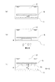
まず、図2(a)に示すように、制御部6は液槽3に液状光硬化性樹脂2を貯留し、その後、可動機構10を制御して基台5を所定位置に配置させる。すなわち、基台5を光透過窓1から所定距離Gだけ離れた位置に配置させる。所定距離Gは造形ギャップGとも呼ばれ、この距離を隔てた光透過窓1と基台5の間の空間には、三次元造形物を形成する原料である液状光硬化性樹脂2が充填されている。造形ギャップGは、例えば1μm以上で200μm以下が好ましく、20μm以上で100μm以下がさらに好ましい。
First, as shown in FIG. 2A, the
次に、図2(b)に示すように、硬化光を照射させる。すなわち、制御部6は、作成すべき三次元造形モデルの一層分の形状データ(スライスデータ)に応じた硬化光の照射パターンを画像形成素子8に伝達し、光源7及び投影レンズ9と連携させて硬化光を照射させる。
光源7には、波長が365nm、385nm、405nmの紫外線光源や、多波長の光が混在する高圧水銀ランプやハロゲンランプなどが好適に用いられる。硬化光(エネルギー線)の強度は格別限定されないが、0.1mW/cm2から1000mW/cm2が好ましく、1mW/cm2から100mW/cm2がさらに好ましい。エネルギー線の照射時間はエネルギー線の強度及び液状光硬化性樹脂2の硬化反応特性から適宜選択できるが、照射量が1mJ/cm2から100mJ/cm2となる照射時間とするのが好ましい。
光透過窓1を通じて照射される硬化光により、三次元造形物の一層が形成されるが、形成される三次元造形物4の一層の厚みをTとすれば、Tは概ね造形ギャップGと等しくなる。
Next, as shown in FIG. 2B, curing light is irradiated. That is, the
As the
One layer of the three-dimensional structure is formed by the curing light irradiated through the
次に、図2(c)に示すように、制御部6は、形成した層と光透過窓1の間に次の一層の原料となる液状光硬化性樹脂2を供給するため、可動機構10を制御して三次元造形物4を保持する基台5を光透過窓1から離れる方向に移動速度V1で移動させる。
本実施形態では、一層の形成を終了した後に基台5を光透過窓1から離れる方向に移動させる移動距離Hを、造形ギャップGよりも大きくする。すなわち、移動距離H>造形ギャップGとなるよう基台5を引上げ、先に形成した層と光透過窓1との間に液状光硬化性樹脂2を流入させる。これは、移動距離H=造形ギャップGとして液状光硬化性樹脂2を流入させるよりも、移動距離H>造形ギャップGとして流入させ、その後で先に形成した層と光透過窓1の距離を造形ギャップGに合わせた方が、樹脂の供給が短時間で完了するからである。移動距離Hは、原材料として使用する液状光硬化性樹脂2の粘度を考慮して、適宜設定する。
Next, as shown in FIG. 2C, the
In the present embodiment, the moving distance H for moving the
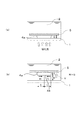
さらに、本実施形態では、次の一層の原料となる液状光硬化性樹脂2を供給する際に、基台5を光透過窓1から離れる方向に移動させる速度を、先に形成した固化層の形状に応じて制御する。図4(a)に示すように固化層4aを形成した後に、図4(b)に示すように基台5を移動させる場合を考える。尚、基台5の速度制御は、一層目の固化層を形成した直後だけには限らず、n層目の固化層を形成した後にn+1層目の原料となる液状光硬化性樹脂2を供給する場合にまで一般化して考えてよい。(ただし、nは1以上の整数)。
Further, in the present embodiment, when the liquid photo-
基台5を光透過窓1から離れる方向に移動させると、液状光硬化性樹脂2は固化層4aの縁(端部)から中央部に向けて矢印FLに沿って固化層4aの底面4Bと光透過窓1の間を流動する。この時に液状光硬化性樹脂2が固化層4aの底面に沿って流動する最大距離を、流動距離Lと呼ぶものとする。
When the
例えば、固化層4aの形状が光透過窓1から見て平面的には円形だとすれば、流動距離Lは円の半径と等しく、当該円が大きければ大きいほど流動距離Lは大きくなる。また、例えば、固化層4aの形状が光透過窓1から見て平面的にはドーナツのような円環形状であれば、円環の内側の縁と外側の縁から液状光硬化性樹脂が流動するので、流動距離Lは円環の幅の1/2に等しくなる。三次元造形物の形状がより複雑であったとしても、制御部6のコンピュータが、三次元造形物の各層の形状データに基づいて幾何学演算や液状光硬化性樹脂の流動シミュレーションを行うことにより、流動距離Lを容易に求めることが可能である。
基台5を光透過窓1から離れる方向に移動させる移動速度Vは、以下の条件を満足するように制御部6により制御される。
For example, if the solidified
The moving speed V for moving the

ただし、α1は定数、Fは三次元造形物を不可逆的に変形または破壊させる限界応力、H0は予め設定した基台を移動させる移動距離、μは液状光硬化性樹脂の粘度である。また、Sは先に形成した固化層が光透過窓と対向する面積、Lは液状光硬化性樹脂が流動する流動距離、である。
液状光硬化性樹脂の供給に要する時間を短縮するためには、数式1の関係を満足する範囲で、できるだけVを大きくするように制御するのが望ましい。
Here, α1 is a constant, F is a limit stress that irreversibly deforms or destroys the three-dimensional structure, H0 is a moving distance for moving a preset base, and μ is a viscosity of the liquid photocurable resin. Further, S is an area where the solidified layer formed previously faces the light transmission window, and L is a flow distance in which the liquid photocurable resin flows.
In order to shorten the time required to supply the liquid photo-curable resin, it is desirable to control V to be as large as possible within the range that satisfies the relationship of
制御部6は、定数α1、限界応力F、粘度μ、移動距離H0の数値を予め記憶しておくとともに、造形モデルの形状に基づき、各固化層の面積Sと流動距離Lを算出する。そして、それらの数値に基づきVの限界値を算出し、限界値を超えないように可動機構10を制御しながら基台5を移動させる。尚、各固化層の面積Sと流動距離Lは、三次元造形工程中に算出しなくとも、予め算出してメモリーに格納しておき、造形の際に読み出してもよい。
尚、可動機構10に荷重測定機構を設けておき、測定される荷重が限界応力Fを超えない範囲で基台5の移動速度を大きくするよう制御するのが望ましい。
The
It is desirable to provide a load measuring mechanism in the
図2(c)に示すように、三次元造形物4の下面が光透過窓1から距離がH=H0になるまで基台5を移動速度V1で移動させて液状光硬化性樹脂2を供給した後、制御部6は、図3(a)に示すように、基台5の位置を制御する。すなわち、三次元造形物4の下面と光透過窓1の距離が造形ギャップGと等しくなる位置まで、可動機構10を制御して基台5を下方向に移動させる。この時の移動速度は、三次元造形物が不可逆的に変形または破壊しない範囲で高速にする。
As shown in FIG. 2C, the
次に、図3(b)に示すように、制御部6は、作成すべき三次元造形モデルの次の一層分の形状データ(スライスデータ)に応じた硬化光の照射パターンを画像形成素子8に伝達し、光源7及び投影レンズ9と連携させて、硬化光を照射させる。図3(b)では、図2(b)で形成した第一層目よりも、光透過窓1側から見て面積が小さな形状の第二層目を形成した例を示している。
Next, as shown in FIG. 3B, the
次に、図3(c)に示すように、制御部6は、形成した層と光透過窓1の間に次の一層の原料となる液状光硬化性樹脂2を供給するため、可動機構10を制御して三次元造形物4を保持する基台5を光透過窓1から離れる方向に移動速度V2で移動させる。この際に、第二層目の固化層は、第一層目に比べて面積Sと流動距離Lが小さな形状を有している。制御部6は、上述した数式1の条件を満足する範囲で移動速度を大きくするように可動機構10を制御するため、図2(c)におけるV1と図3(c)におけるV2とを比較すれば、V2>V1の関係になる。
Next, as shown in FIG. 3C, the
このようにして、第三層目の固化層の原料となる液状硬化性樹脂を供給し、以下同様の手順を繰返して固化層を次々と積層してゆき、三次元造形物を完成させる。三次元造形物を液槽3から取り出し、基台5から取外した後、未硬化の光硬化性樹脂の付着を取り除くための洗浄を行ってもよい。また、硬化不足の光硬化性樹脂の硬化促進や、成形時の残留応力を緩和させるため、加熱アニール、エネルギー線の追加照射、無酸素雰囲気での加熱やエネルギー線照射などを行ってもよい。
In this way, the liquid curable resin which is the raw material of the third solidified layer is supplied, and the same procedure is repeated thereafter to successively stack the solidified layers to complete the three-dimensional structure. After removing the three-dimensional structure from the liquid tank 3 and removing it from the
本実施形態による三次元造形の好適な適用例としては、カメラ、プリンター、液晶プロジェクター用の外装部品の製造などが挙げられる。高粘度の液体状光硬化性樹脂を用いる場合でも、三次元造形物に過大な力をかけることなく造形領域に液体状光硬化性樹脂を短時間で供給することができる。各層を形成するための液状硬化性樹脂の供給時間の総和が短縮されるため、高い形状精度と歩留まりを維持しながら、製造のスループットを向上させることができる。 Suitable application examples of the three-dimensional modeling according to the present embodiment include manufacturing of exterior parts for cameras, printers, liquid crystal projectors, and the like. Even when the high-viscosity liquid photo-curable resin is used, the liquid photo-curable resin can be supplied to the modeling area in a short time without applying an excessive force to the three-dimensional structure. Since the total supply time of the liquid curable resin for forming each layer is shortened, it is possible to improve the manufacturing throughput while maintaining high shape accuracy and yield.
[実施形態2]
実施形態2は、実施形態1に対して、三次元造形方法が異なる。光硬化性樹脂や三次元造形装置の基本構成は実施形態1と同様または類似であるので、ここでは説明を省略する。
実施形態1では、基台の移動距離Hは、原材料として使用する液状光硬化性樹脂2の粘度を考慮して決めた一定値とし、基台を光透過窓から離間させる際の基台の移動速度Vを、先に形成した硬化層の形状に応じて変更した。これに対して、実施形態2の三次元造形方法では、先に形成した硬化層の形状に応じて、移動距離Hと移動速度Vの両方を変更する。
[Embodiment 2]
The second embodiment differs from the first embodiment in the three-dimensional modeling method. The basic configurations of the photo-curable resin and the three-dimensional modeling device are the same as or similar to those in the first embodiment, and thus the description thereof is omitted here.
In the first embodiment, the moving distance H of the base is a fixed value determined in consideration of the viscosity of the liquid
[三次元造形方法]
実施形態1と異なる部分を中心に説明する。
本実施形態では、次の一層の原料となる液状光硬化性樹脂2を供給する際に、基台5を光透過窓1から離れる方向に移動させる速度を、先に形成した固化層の形状に応じて制御する。図4(a)に示すように固化層4aを形成した後に、図4(b)に示すように基台5を移動させる場合を考える。尚、基台5の速度制御は、一層目の固化層を形成した場合だけには限らず、n層目の固化層を形成した後にn+1層目の原料となる液状光硬化性樹脂2を供給する場合にまで一般化して考えてよい。(ただし、nは1以上の整数)。
[3D modeling method]
The description will focus on the parts that differ from the first embodiment.
In the present embodiment, when the liquid
基台5を光透過窓1から離れる方向に移動させると、液状光硬化性樹脂2は固化層4aの縁(端部)から中央部に向けて矢印FLに沿って固化層4aと光透過窓1の間を流動する。この時に液状光硬化性樹脂2が固化層4aの底面に沿って流動する最大距離を、流動距離Lと呼ぶものとする。
まず、以下の数式2に基づき、基台5を光透過窓1から離れる方向に移動させる概略速度VTを求める。
When the
First, the approximate speed VT for moving the
ただし、α1は定数、Fは三次元造形物を不可逆的に変形または破壊させる限界応力、μは液状光硬化性樹脂の粘度、Sは先に形成した固化層が光透過窓と対向する面積、Lは液状光硬化性樹脂が流動する流動距離、である。また、Jは原材料として使用する液状光硬化性樹脂2の粘度を考慮して適宜設定する定数で、仮に定める移動距離である。
Here, α1 is a constant, F is the limit stress that irreversibly deforms or destroys the three-dimensional structure, μ is the viscosity of the liquid photocurable resin, S is the area where the solidified layer previously formed faces the light transmission window, L is a flow distance over which the liquid photocurable resin flows. Further, J is a constant that is appropriately set in consideration of the viscosity of the liquid
次に、本実施形態では、数式2で求めた概略速度VTから、以下の数式3に基づき、次の一層の原料となる液状光硬化性樹脂2を供給する際に、基台5を光透過窓1から離れる方向に移動させる移動距離Hを決定する。
Next, in the present embodiment, when the liquid
ただし、α2は1よりも大きな定数、VTは数式2で決定した概略速度、μは液状光硬化性樹脂の粘度、Lは液状光硬化性樹脂が流動する流動距離である。
However, α2 is a constant larger than 1, VT is the approximate speed determined by the
さらに、本実施形態では、数式3で求めたHから、以下の数式4に基づき、基台5を光透過窓1から離れる方向に移動させる移動速度Vを求める。
Further, in the present embodiment, the moving speed V for moving the
ただし、α1は定数、Fは三次元造形物を不可逆的に変形または破壊させる限界応力、μは液状光硬化性樹脂の粘度、Sは先に形成した固化層が光透過窓と対向する面積、Lは液状光硬化性樹脂が流動する流動距離である。また、Hは、数式3で求めた基台5を光透過窓1から離れる方向に移動させる距離である。
Here, α1 is a constant, F is the limit stress that irreversibly deforms or destroys the three-dimensional structure, μ is the viscosity of the liquid photocurable resin, S is the area where the solidified layer previously formed faces the light transmission window, L is a flow distance in which the liquid photocurable resin flows. Further, H is a distance to move the
制御部6は、定数α1、限界応力F、粘度μ、定数J、定数α2の数値を予め記憶しておくとともに、造形モデルの形状に基づき、各固化層の面積Sと流動距離Lを算出する。そして、それらの数値に基づきV及びHを算出し、可動機構10を制御しながら基台5を移動させる。尚、各固化層の面積Sと流動距離Lは、三次元造形工程中に算出しなくとも、予め算出してメモリーに格納しておき、造形の際に読み出してもよい。
尚、可動機構10に荷重測定機構を設けておき、測定される荷重が限界応力Fを超えないよう制御するのが望ましい。
The
It is desirable that the
図2(c)と図3(c)を例に挙げれば、第二層目の固化層は、第一層目に比べて面積Sと流動距離Lが小さな形状を有している。制御部6は、上述した数式2および数式3を満足するように可動機構10を制御するため、図2(c)におけるV1と図3(c)におけるV2とを比較すれば、V2>V1の関係になる。また、図2(c)におけるHの方が図3(c)におけるHよりも大きくなる。
Taking FIG. 2C and FIG. 3C as an example, the second solidified layer has a shape in which the area S and the flow distance L are smaller than the first layer. Since the
このようにして、第三層目の固化層の原料となる液状硬化性樹脂を供給し、以下同様の手順を繰返して固化層を次々と積層してゆき、三次元造形物を完成させる。三次元造形物を液槽3から取り出し、基台5から取外した後、未硬化の液状光硬化性樹脂の付着を取り除くための洗浄を行ってもよい。また、硬化不足の光硬化性樹脂の硬化促進や、成形時の残留応力を緩和させるため、加熱アニール、エネルギー線の追加照射、無酸素雰囲気での加熱やエネルギー線照射などを行ってもよい。
In this way, the liquid curable resin which is the raw material of the third solidified layer is supplied, and the same procedure is repeated thereafter to successively stack the solidified layers to complete the three-dimensional structure. After removing the three-dimensional structure from the liquid tank 3 and removing it from the
本実施形態による三次元造形の好適な適用例としては、カメラ、プリンター、液晶プロジェクター用の外装部品の製造などが挙げられる。高粘度の液体状光硬化性樹脂を用いる場合でも、三次元造形物に過大な力をかけることなく造形領域に液体状光硬化性樹脂を短時間で供給することができる。各層を形成するための液状硬化性樹脂の供給時間の総和が短縮されるため、高い形状精度と歩留まりを維持しながら、製造のスループットを向上させることができる。 Suitable application examples of the three-dimensional modeling according to the present embodiment include manufacturing of exterior parts for cameras, printers, liquid crystal projectors, and the like. Even when the high-viscosity liquid photo-curable resin is used, the liquid photo-curable resin can be supplied to the modeling area in a short time without applying an excessive force to the three-dimensional structure. Since the total supply time of the liquid curable resin for forming each layer is shortened, it is possible to improve the manufacturing throughput while maintaining high shape accuracy and yield.
以下に、本発明の実施例および比較例について説明する。実施例および比較例では、以下の三次元造形装置を用いて三次元造形方法を実施し、その三次元造形速度を評価した。すなわち、三次元造形装置の光透過窓として、材質がBK7ガラス、寸法が80mm×80mm×5mm厚みの平板で、光透過窓上面に以下の構造物を設けたものを用いた。また、エネルギー線照射装置の光源として、波長が405nmのLED光源を用いた。画像形成素子として、テキサスインスツルメンツ製のFull−HDデジタルミラーデバイスを用いた。投影レンズとして、一画素のサイズを60μm×60μmに投影する光学系を設計したレンズを用いた。エネルギー線が照射される最大のサイズはおよそ115mm×65mmである。 Examples and comparative examples of the present invention will be described below. In Examples and Comparative Examples, the three-dimensional modeling method was carried out using the following three-dimensional modeling apparatus, and the three-dimensional modeling speed was evaluated. That is, as the light transmission window of the three-dimensional modeling apparatus, a material having a material of BK7 glass, a flat plate having dimensions of 80 mm × 80 mm × 5 mm, and having the following structure provided on the upper surface of the light transmission window was used. An LED light source with a wavelength of 405 nm was used as the light source of the energy ray irradiation device. As an image forming element, a Full-HD digital mirror device manufactured by Texas Instruments was used. As the projection lens, a lens having an optical system designed to project one pixel size to 60 μm × 60 μm was used. The maximum size of the energy beam irradiated is approximately 115 mm × 65 mm.
[実施例1]
実施形態1の具体例として、実施例1を示す。まず、粘度が1Pa・sの紫外線硬化するアクリル樹脂を液状光硬化性樹脂として液槽に投入し、基台と光透過窓の間隔が20μmとなるように接近させた。以下、本実施例の造形を行う間の造形ギャップは、20μmの一定値とした。造形物の形状は、底面の半径が10mm、高さが20mmの円錐形状とした。底面から造形する場合、三次元形状から得られる1層目形状は半径10mmの円であり、投影映像が半径10mmの円となるようにエネルギー線を照射した。このとき、エネルギー線の強度は100mW/cm2であった。エネルギー線の照射を0.1秒間照射した後、エネルギー線の照射を停止し基台を移動させた。
[Example 1]
Example 1 will be shown as a specific example of the first embodiment. First, an ultraviolet curable acrylic resin having a viscosity of 1 Pa · s was charged as a liquid photocurable resin into a liquid tank, and they were brought close to each other so that the distance between the base and the light transmission window was 20 μm. Hereinafter, the modeling gap during the modeling of this example was set to a constant value of 20 μm. The shape of the modeled object was a conical shape with a bottom radius of 10 mm and a height of 20 mm. When modeling from the bottom surface, the first layer shape obtained from the three-dimensional shape is a circle with a radius of 10 mm, and the energy ray was irradiated so that the projected image was a circle with a radius of 10 mm. At this time, the intensity of the energy rays was 100 mW /
この時の移動速度は、前層の形状に対応して決定される。演算装置で各層の形状データに基づいて計算してもよいし、予め演算しておき1層毎の移動速度が設定されたデータベースを用意しても良い。
本実施例の造形形状である円錐の最長の流入距離は円の半径であり、造形を円錐の底面から始めるとすると、高さhのときの半径rは−1/2×h+10で計算される。また、限界応力Fは用いる光硬化性樹脂による異なる値であるが、本実施例では、曲げ強さFは120MPaとした。尚、第1層の最長の流入距離は10mmであり、例えば数式1において、L=10mm、H=530μm、樹脂の粘度μ=1Pa・s、α1=0.67、F=120MPaとし、移動速度の上限値を計算すると、V<6.4mm/secとなる。
The moving speed at this time is determined according to the shape of the front layer. The calculation may be performed based on the shape data of each layer by a calculation device, or a database in which the moving speed for each layer is set may be prepared by performing a calculation in advance.
The longest inflow distance of the cone having the modeling shape of the present embodiment is the radius of the circle, and if the modeling is started from the bottom surface of the cone, the radius r at the height h is calculated as −1 / 2 × h + 10. . Further, the limiting stress F has different values depending on the photocurable resin used, but in this example, the bending strength F was 120 MPa. The longest inflow distance of the first layer is 10 mm. For example, in
基台を、前層の形状に応じて決まる速度上限値を超えない範囲で、できるだけ高速度で距離530μmだけ移動させ、樹脂を十分に充填させた後、造形ギャップである20μmまで戻して、再び、断面データの投影を行う。これを繰り返し行うことで、三次元造形物の完成品が得られ、この時の平均造形速度は5.5mm/minであった。 The base is moved at a speed as high as possible for a distance of 530 μm within a range not exceeding the upper limit of speed determined by the shape of the front layer, and after being sufficiently filled with resin, returned to the molding gap of 20 μm, and then again. , Project the cross-section data. By repeating this, a finished product of the three-dimensional modeled product was obtained, and the average modeling speed at this time was 5.5 mm / min.
[実施例2]
実施形態2の具体例として、実施例2を示す。実施例1では、移動量を固定値(H=530μm)にして、三次元造形物の前層の形状により、移動速度Vを制御する造形装置を示した。これに対して、実施例2は、移動量と移動速度Vの両方を、前層の形状に対応して変更し、高速に造形する。
[Example 2]
Example 2 will be shown as a specific example of the second embodiment. In the first embodiment, the modeling apparatus is shown in which the migration amount is fixed (H = 530 μm) and the migration speed V is controlled by the shape of the front layer of the three-dimensional model. On the other hand, in the second embodiment, both the moving amount and the moving speed V are changed according to the shape of the front layer, and the molding is performed at high speed.
本実施例の造形形状は、実施例1と同様で、底面の半径が10mm、高さが20mmの円錐形状とした。この場合、三次元形状から得られる層形状は円形であり、投影映像が対応した半径の円となるようにエネルギー線を照射した。このとき、エネルギー線の強度は100mW/cm2であった。エネルギー線の照射を0.1秒間照射した後、エネルギー線の照射を停止し基台を移動させた。
The modeling shape of this example was the same as that of Example 1, and was a conical shape with a bottom surface radius of 10 mm and a height of 20 mm. In this case, the layer shape obtained from the three-dimensional shape was circular, and the energy ray was irradiated so that the projected image was a circle having a corresponding radius. At this time, the intensity of the energy rays was 100 mW /
まず、α1=0.67、J=530μm、樹脂の粘度μ=1Pa・s、F=120MPaとして、数式2に基づき、前層の形状に応じて決まる概略速度VTを求める。そして、そのVTを用いて、数式3に基づき、前層の形状に応じて決まる移動距離Hを求める。そして、そのHを用いて、数式4に基づき、前層の形状に応じて決まる移動速度Vを求める。
First, assuming that α1 = 0.67, J = 530 μm, resin viscosity μ = 1 Pa · s, and F = 120 MPa, the approximate speed VT determined according to the shape of the front layer is calculated based on
例えば、造形形状の第1層の形状から求められた流入距離10mm、光硬化性樹脂の粘度1Pa・s、移動速度の6.4mm/secから移動量を計算すると、330μmとなる。また、同様に別の層についての計算を行うと、流入距離5mmの形状の移動量は520μmとなる。このように、前層の形状により移動量を変化させると、より高速な造形を行うことが可能となる。この時の移動量は、演算装置で形状データに基づいて計算してもよいし、予め1層毎の移動量を演算して記憶したデータベースを用意しても良い。造形精度を保つために造形ギャップまで光透過窓に基台を接近させ、エネルギー線照射による硬化を行い、さらに樹脂流入のための基台の移動を繰り返し行うことで、三次元造形物の完成品が得られ、この時の平均造形速度は5.6mm/minであった。 For example, when the amount of movement is calculated from the inflow distance of 10 mm obtained from the shape of the first layer having a modeling shape, the viscosity of the photocurable resin of 1 Pa · s, and the moving speed of 6.4 mm / sec, it becomes 330 μm. Similarly, when the calculation is performed for another layer, the movement amount of the shape having the inflow distance of 5 mm is 520 μm. In this way, by changing the movement amount according to the shape of the front layer, it becomes possible to perform higher-speed modeling. The movement amount at this time may be calculated by a calculation device based on the shape data, or a database in which the movement amount for each layer is calculated and stored in advance may be prepared. In order to maintain molding accuracy, the base is brought close to the light transmission window up to the molding gap, curing is performed by energy ray irradiation, and the base is moved repeatedly for resin inflow, thus completing the three-dimensional modeled product. Was obtained, and the average modeling speed at this time was 5.6 mm / min.
[比較例1]
実施例1、2と同じ造形形状である底面の半径が10mm、高さが20mmの円錐について、特許文献1をもとに、移動速度、移動量を一定とした造形を行った。この場合、三次元形状から得られる形状データは円状であり、投影映像が対応した半径の円となるようにエネルギー線を照射した。このとき、エネルギー線の強度は100mW/cm2であった。エネルギー線の照射を0.1秒間照射した後、エネルギー線の照射を停止し基台を移動させた。光硬化性樹脂の粘度が1Pa・sの紫外線硬化するアクリル樹脂であることを考慮した、造形不良のないように、移動速度は6.4mm/sec、移動量は530μmに設定した。造形精度を保つために造形ギャップまで基台の光透過窓への接近、エネルギー線照射による硬化、樹脂流入のための基台の移動を繰り返し行うことで、三次元造形形状が得られ、この時の平均造形速度は4.2mm/minであった。
[Comparative Example 1]
A cone having a bottom surface radius of 10 mm and a height of 20 mm, which has the same molding shape as in Examples 1 and 2, was molded based on
[実施例3]
実施形態1の具体例として、実施例3を示す。光硬化性樹脂として、粘度が10Pa・sの高粘度の紫外線硬化するアクリル樹脂を用い、半径が10mmの球形状を造形した。この場合、三次元形状から得られる層形状は円であり、投影映像が対応した半径の円となるようにエネルギー線を照射した。このとき、エネルギー線の強度は100mW/cm2であった。エネルギー線の照射を0.1秒間照射した後、エネルギー線の照射を停止し基台を移動させた。移動量は、760μmの固定値とした。この時の移動速度の上限は、前層の形状に対応して数式1に基づいて決定される。
[Example 3]
Example 3 is shown as a specific example of the first embodiment. As the photocurable resin, a highly viscous UV-curable acrylic resin having a viscosity of 10 Pa · s was used, and a spherical shape having a radius of 10 mm was formed. In this case, the layer shape obtained from the three-dimensional shape is a circle, and the energy ray was irradiated so that the projected image was a circle having a corresponding radius. At this time, the intensity of the energy rays was 100 mW /
例えば、半径が8mmの前層形状に対応した移動速度は、曲げ強さFを120MPaとし、最長の流入距離4mmと樹脂の粘度10Pa・sから移動速度を計算すると、上限が24.7mm/secとなる。
基台を移動させ、樹脂を十分に充填させた後、造形ギャップである20μmまで戻して、今回の層形状に応じた照射パターンの投影を行う。これを繰り返し行うことで、三次元造形物の完成品が得られ、この時の平均造形速度は1.9mm/minであった。
For example, when the bending speed F is 120 MPa and the moving speed corresponding to the front layer shape having a radius of 8 mm is calculated from the longest inflow distance of 4 mm and the resin viscosity of 10 Pa · s, the upper limit is 24.7 mm / sec. Becomes
After the base is moved and the resin is sufficiently filled, it is returned to the modeling gap of 20 μm, and the irradiation pattern according to the layer shape of this time is projected. By repeating this, a finished product of the three-dimensional model was obtained, and the average modeling speed at this time was 1.9 mm / min.
[実施例4]
実施形態2の具体例として、実施例4を示す。本実施例の造形形状は、実施例3と同様で半径が10mmの球形状を造形した。この場合、三次元形状から得られる層形状は円であり、投影映像が対応した半径の円となるようにエネルギー線を照射した。このとき、エネルギー線の強度は100mW/cm2であった。エネルギー線の照射を0.1秒間照射した後、エネルギー線の照射を停止し基台を移動させた。
[Example 4]
Example 4 is shown as a specific example of the second embodiment. The modeling shape of this example was the same as that of Example 3, and a spherical shape having a radius of 10 mm was modeled. In this case, the layer shape obtained from the three-dimensional shape is a circle, and the energy ray was irradiated so that the projected image was a circle having a corresponding radius. At this time, the intensity of the energy rays was 100 mW /
例えば、半径8mmの前層形状に対応する場合には、曲げ強さFを120MPaとし、樹脂の粘度10Pa・s、最長の流入距離4mmを基に、数式4から移動速度は24.7mm/secと計算される。この時の移動量は、数式3から605μmと計算された。
このように、前層の形状により移動量と移動速度を変化させると、より高速な造形を行うことが可能となる。造形精度を保つために造形ギャップまで光透過窓へ基台を接近させ、エネルギー線照射により硬化し、樹脂流入のための基台の移動を繰り返し行うことで、三次元造物の完成品が得られ、この時の平均造形速度は2.4mm/minであった。
For example, when it corresponds to the front layer shape having a radius of 8 mm, the bending strength F is 120 MPa, the resin viscosity is 10 Pa · s, and the longest inflow distance is 4 mm. Is calculated. The amount of movement at this time was calculated from Equation 3 to be 605 μm.
In this way, by changing the movement amount and the movement speed depending on the shape of the front layer, it becomes possible to perform higher-speed molding. In order to maintain the modeling accuracy, the base is brought close to the light transmission window up to the modeling gap, it is cured by irradiation with energy rays, and the base is moved repeatedly for resin inflow to obtain a finished product of the three-dimensional structure. The average modeling speed at this time was 2.4 mm / min.
[比較例2]
実施例3、4と同じ造形形状である半径が10mmの球について、特許文献1をもとに、退避速度、移動量を一定とした造形を行った。この場合、三次元形状から得られる層形状は円であり、投影映像が対応した半径の円となるようにエネルギー線を照射した。このとき、エネルギー線の強度は100mW/cm2であった。エネルギー線の照射を0.1秒間照射した後、エネルギー線の照射を停止し基台を移動させた。光硬化性樹脂の粘度が10Pa・sの紫外線硬化するアクリル樹脂であることを考慮し、造形不良のないように、移動速度は0.64mm/sec、移動量は760μmとした。造形精度を保つために造形ギャップまで光透過窓へ基台を接近させ、エネルギー線照射により硬化し、樹脂流入のための基台の移動を繰り返し行うことで、三次元造形物の完成品が得られ、この時の平均造形速度は0.9mm/minであった。
[Comparative Example 2]
With respect to a sphere having a radius of 10 mm, which is the same modeling shape as in Examples 3 and 4, modeling was performed based on
以上の実施例と比較例から明らかなように、同一形状の三次元造形物を作成する場合には、本発明の実施例は、従来の方法による比較例に比べて、高速に造形処理を行うことが可能である。特に、液状光硬化性樹脂の粘度μが、1Pa・s以上で30Pa・s以下の範囲において、高速化が顕著であった。 As is clear from the above examples and comparative examples, when a three-dimensional modeled object having the same shape is created, the example of the present invention performs modeling processing at a higher speed than the comparative example by the conventional method. It is possible. In particular, when the viscosity μ of the liquid photocurable resin was in the range of 1 Pa · s or more and 30 Pa · s or less, the speedup was remarkable.
[他の実施形態]
本発明の実施形態は、上述した実施形態1〜実施形態2、および各実施例に限られるものではなく、本発明の技術的思想内で多くの変形が可能である。
本発明は、上述の実施形態の1以上の機能を実現するプログラムを、ネットワーク又は記憶媒体を介してシステム又は装置に供給し、そのシステム又は装置のコンピュータにおける1つ以上のプロセッサーがプログラムを読出し実行する処理でも実現可能である。また、1以上の機能を実現する回路(例えば、ASIC)によっても実現可能である。
[Other Embodiments]
The embodiment of the present invention is not limited to the above-described first to second embodiments and each example, and many modifications can be made within the technical idea of the present invention.
The present invention supplies a program that realizes one or more functions of the above-described embodiments to a system or apparatus via a network or a storage medium, and one or more processors in a computer of the system or apparatus read and execute the program. It can also be realized by the processing. It can also be realized by a circuit (for example, ASIC) that realizes one or more functions.
1・・・光透過窓/2・・・液状光硬化性樹脂/3・・・液槽/4・・・三次元造形物/4a・・・固化層/4B・・・底面/5・・・基台/6・・・制御部/7・・・光源/8・・・画像形成素子/9・・・投影レンズ/10・・・可動機構 1 ... Light-transmissive window / 2 ... Liquid photo-curable resin / 3 ... Liquid tank / 4 ... Three-dimensional model / 4a ... Solidified layer / 4B ... Bottom / 5 ... -Base / 6 ... Control unit / 7 ... Light source / 8 ... Image forming element / 9 ... Projection lens / 10 ... Movable mechanism
Claims (14)
基台と、
光源と、を備え、
前記光源から前記光透過窓を通して前記液状光硬化性樹脂に硬化光を照射して硬化層を形成することを繰り返して、前記基台に複数の硬化層を積層して三次元造形物を形成するが、
一の硬化層の形成を終了した後に、次に形成する硬化層の原料となる前記液状光硬化性樹脂を前記一の硬化層と前記透過窓の間に供給するため前記基台を前記光透過窓から離間する方向に移動させるが、
供給する時に前記液状光硬化性樹脂が前記一の硬化層の端部から内側に向けて流動する最大距離をLとした時、前記一の硬化層の形状がLの大きな形状であるほど、前記基台を前記光透過窓から離間する方向に移動させる移動速度Vを小さくする、
ことを特徴とする三次元造形装置。 A container that can store a liquid photocurable resin and has a light transmission window,
A base,
A light source,
Irradiating curing light to the liquid photocurable resin from the light source through the light transmission window to form a curing layer is repeated to form a three-dimensional structure by laminating a plurality of curing layers on the base. But,
After the formation of the one hardened layer is completed, the liquid photocurable resin, which is a raw material of the next hardened layer, is supplied between the one hardened layer and the transmission window so that the base is light-transmitted. Move it away from the window,
When the maximum distance that the liquid photocurable resin flows inward from the end of the one cured layer when supplied is L, the larger the shape of the one cured layer is, the more The moving speed V for moving the base in the direction away from the light transmission window is reduced.
A three-dimensional modeling device characterized in that
ことを特徴とする請求項1に記載の三次元造形装置。 The larger the area of the one hardened layer is, the smaller the moving speed V is,
The three-dimensional modeling apparatus according to claim 1, characterized in that.
ことを特徴とする請求項1または2に記載の三次元造形装置。 The higher the viscosity μ of the liquid photocurable resin is, the smaller the moving speed V is,
The three-dimensional modeling apparatus according to claim 1 or 2, characterized in that.
ことを特徴とする請求項1から3のいずれか1項に記載の三次元造形装置。 The viscosity μ of the liquid photocurable resin is 1 Pa · s or more and 30 Pa · s or less,
The three-dimensional modeling apparatus according to any one of claims 1 to 3, characterized in that
ことを特徴とする請求項1から4のいずれか1項に記載の三次元造形装置。
The three-dimensional modeling apparatus according to any one of claims 1 to 4, characterized in that.
ことを特徴とする請求項1から4のいずれか1項に記載の三次元造形装置。 The larger the shape of the one cured layer is, the larger the moving distance H of the base when moving the base in the direction away from the light transmission window is.
The three-dimensional modeling apparatus according to any one of claims 1 to 4, characterized in that.
ことを特徴とする請求項6に記載の三次元造形装置。
The three-dimensional modeling apparatus according to claim 6, wherein.
基台と、
光源と、を備えた三次元造形装置を用い、
前記光源から前記光透過窓を通して前記液状光硬化性樹脂に硬化光を照射して硬化層を形成することを繰り返して、前記基台に複数の硬化層を積層して三次元造形物を形成する三次元造形方法において、
一の硬化層の形成を終了した後に、次に形成する硬化層の原料となる前記液状光硬化性樹脂を前記一の硬化層と前記透過窓の間に供給するため前記基台を前記光透過窓から離間する方向に移動させるが、
供給する時に前記液状光硬化性樹脂が前記一の硬化層の端部から内側に向けて流動する最大距離をLとした時、前記一の硬化層の形状がLの大きな形状であるほど、前記基台を前記光透過窓から離間する方向に移動させる移動速度Vを小さくする、
ことを特徴とする三次元造形方法。 A container that can store a liquid photocurable resin and has a light transmission window,
A base,
Using a three-dimensional modeling device equipped with a light source,
Irradiating curing light to the liquid photocurable resin from the light source through the light transmission window to form a curing layer is repeated to form a three-dimensional structure by laminating a plurality of curing layers on the base. In the three-dimensional modeling method,
After the formation of the one hardened layer is completed, the liquid photocurable resin, which is a raw material of the next hardened layer, is supplied between the one hardened layer and the transmission window so that the base is light-transmitted. Move it away from the window,
When the maximum distance that the liquid photocurable resin flows from the end of the one cured layer toward the inside when supplied is L, the larger the shape of the one cured layer is, the more The moving speed V for moving the base in the direction away from the light transmission window is reduced.
A three-dimensional modeling method characterized by that.
ことを特徴とする請求項8に記載の三次元造形方法。 The larger the area of the one hardened layer is, the smaller the moving speed V is,
The three-dimensional modeling method according to claim 8, wherein.
ことを特徴とする請求項8または9に記載の三次元造形方法。 The higher the viscosity μ of the liquid photocurable resin is, the smaller the moving speed V is,
The three-dimensional modeling method according to claim 8 or 9, characterized in that.
ことを特徴とする請求項8から10のいずれか1項に記載の三次元造形方法。 The viscosity μ of the liquid photocurable resin is 1 Pa · s or more and 30 Pa · s or less,
The three-dimensional modeling method according to any one of claims 8 to 10, characterized in that.
ことを特徴とする請求項8から11のいずれか1項に記載の三次元造形方法。
The three-dimensional modeling method according to any one of claims 8 to 11, characterized in that.
ことを特徴とする請求項8から11のいずれか1項に記載の三次元造形方法。 The larger the shape of the one cured layer is, the larger the moving distance H of the base when moving the base in the direction away from the light transmission window is.
The three-dimensional modeling method according to any one of claims 8 to 11, characterized in that.
ことを特徴とする請求項13に記載の三次元造形方法。
The three-dimensional modeling method according to claim 13, wherein.
Priority Applications (1)
| Application Number | Priority Date | Filing Date | Title |
|---|---|---|---|
| JP2018196933A JP2020062841A (en) | 2018-10-18 | 2018-10-18 | Three-dimensional modeling apparatus and three-dimensional modeling method |
Applications Claiming Priority (1)
| Application Number | Priority Date | Filing Date | Title |
|---|---|---|---|
| JP2018196933A JP2020062841A (en) | 2018-10-18 | 2018-10-18 | Three-dimensional modeling apparatus and three-dimensional modeling method |
Publications (1)
| Publication Number | Publication Date |
|---|---|
| JP2020062841A true JP2020062841A (en) | 2020-04-23 |
Family
ID=70388032
Family Applications (1)
| Application Number | Title | Priority Date | Filing Date |
|---|---|---|---|
| JP2018196933A Pending JP2020062841A (en) | 2018-10-18 | 2018-10-18 | Three-dimensional modeling apparatus and three-dimensional modeling method |
Country Status (1)
| Country | Link |
|---|---|
| JP (1) | JP2020062841A (en) |
-
2018
- 2018-10-18 JP JP2018196933A patent/JP2020062841A/en active Pending
Similar Documents
| Publication | Publication Date | Title |
|---|---|---|
| Kowsari et al. | High-efficiency high-resolution multimaterial fabrication for digital light processing-based three-dimensional printing | |
| US10308007B2 (en) | Mask video projection based stereolithography with continuous resin flow | |
| CN105922587B (en) | A kind of continuous photocuring 3D printing equipment and its application method | |
| JP6849365B2 (en) | Stereolithography equipment, stereolithography method and stereolithography program | |
| JP6058819B2 (en) | 3D object production | |
| CN104085106A (en) | DLP principle based 3D printer | |
| CN109689342B (en) | Method for curing photopolymerizable diffuse reflective materials | |
| EP3914437B1 (en) | System for additive manufacturing | |
| WO2007023724A1 (en) | Stereolithography apparatus and stereolithography method | |
| CN108351498B (en) | Device for producing three-dimensional objects and use thereof | |
| JP4824382B2 (en) | Optical three-dimensional modeling method and apparatus | |
| US20220176623A1 (en) | Thermal control in a stereolithographic 3d printer | |
| CN111168996A (en) | Photosensitive resin dip-forming apparatus and method | |
| JP2020062841A (en) | Three-dimensional modeling apparatus and three-dimensional modeling method | |
| JP6866152B2 (en) | 3D modeling device and 3D modeling method | |
| JPH0523588B2 (en) | ||
| JP2019142197A (en) | Molding apparatus, container, and manufacturing method of molding | |
| CN113276408A (en) | Continuous photocuring forming additive manufacturing device in liquid and manufacturing method thereof | |
| KR20040102531A (en) | Micro-stereolithography method and apparatus | |
| JP4626446B2 (en) | Stereolithography apparatus and stereolithography method | |
| CN114008619A (en) | Method and system for outputting a manufacturing document for producing an optical element | |
| US11919235B2 (en) | Techniques for generation and direction of light in additive fabrication and related systems and methods | |
| JP6783586B2 (en) | Manufacturing method of 3D modeling equipment and 3D modeled objects | |
| JP7066459B2 (en) | 3D modeling device and 3D modeling method | |
| CN215151851U (en) | Continuous photocuring molding additive manufacturing device in liquid |
Legal Events
| Date | Code | Title | Description |
|---|---|---|---|
| RD02 | Notification of acceptance of power of attorney |
Free format text: JAPANESE INTERMEDIATE CODE: A7422 Effective date: 20200206 |
|
| RD04 | Notification of resignation of power of attorney |
Free format text: JAPANESE INTERMEDIATE CODE: A7424 Effective date: 20200207 |