JP2020058394A - Smoking system, power feeding control method, program, primary device and secondary device - Google Patents

Smoking system, power feeding control method, program, primary device and secondary device Download PDF

Info

Publication number
JP2020058394A
JP2020058394A JP2020008827A JP2020008827A JP2020058394A JP 2020058394 A JP2020058394 A JP 2020058394A JP 2020008827 A JP2020008827 A JP 2020008827A JP 2020008827 A JP2020008827 A JP 2020008827A JP 2020058394 A JP2020058394 A JP 2020058394A
Authority
JP
Japan
Prior art keywords
mode
aerosol
transition
power supply
primary device
Prior art date
Legal status (The legal status is an assumption and is not a legal conclusion. Google has not performed a legal analysis and makes no representation as to the accuracy of the status listed.)
Pending
Application number
JP2020008827A
Other languages
Japanese (ja)
Inventor
拓磨 中野
Takuma Nakano
拓磨 中野
創 藤田
So Fujita
創 藤田
Current Assignee (The listed assignees may be inaccurate. Google has not performed a legal analysis and makes no representation or warranty as to the accuracy of the list.)
Japan Tobacco Inc
Original Assignee
Japan Tobacco Inc
Priority date (The priority date is an assumption and is not a legal conclusion. Google has not performed a legal analysis and makes no representation as to the accuracy of the date listed.)
Filing date
Publication date
Application filed by Japan Tobacco Inc filed Critical Japan Tobacco Inc
Priority to JP2020008827A priority Critical patent/JP2020058394A/en
Publication of JP2020058394A publication Critical patent/JP2020058394A/en
Priority to JP2021179968A priority patent/JP7230152B2/en
Priority to JP2023020517A priority patent/JP2023053286A/en
Pending legal-status Critical Current

Links

Images

Abstract

To smoothly switch a mode between a charging mode and a direct heating mode.SOLUTION: A smoking system comprises: a secondary device including a load for atomizing an aerosol source or heating a flavor source, and a power supply capable of feeding electric power to the load; a primary device capable of feeding electric power to the load and the power supply when the primary device is connected to the secondary device; and a control unit capable of executing a first mode for feeding electric power from the primary device to the load, and a second mode for feeding electric power from the primary device to the power supply. The control unit executes a transition mode having a transition period for changing a predefined variable related to power feeding between the first mode and the second mode, in at least one of first transition which is transition from the first mode to the second mode and second transition from the second mode to the first mode.SELECTED DRAWING: Figure 4A

Description

本発明は、喫煙システム、給電制御方法、プログラム、一次装置、及び二次装置に関する。   The present invention relates to a smoking system, a power feeding control method, a program, a primary device, and a secondary device.

エアロゾル発生物品を電気ヒータで加熱する加熱装置を、所定回数の喫煙の度に、携帯式の充電器で充電する喫煙システムが知られている(例えば特許文献1参照)。特に、エアロゾル発生物品からエアロゾルを放出するのに多くの電力が必要となる場合、充電の間は喫煙ができないため、連続した喫煙をすることは不可能であった。   BACKGROUND ART A smoking system is known in which a heating device that heats an aerosol-generating article with an electric heater is charged with a portable charger every predetermined number of times of smoking (see Patent Document 1, for example). In particular, when a large amount of electric power is required to discharge the aerosol from the aerosol-generating article, it is not possible to smoke during charging, so continuous smoking is impossible.

この問題に対処するために、例えば特許文献2に開示されるように、充電器から直接ヒータへ給電してエアロゾルを発生させることが考えられる。この場合、従来のように充電器から加熱装置の内蔵充電池を充電するモードと、充電器からヒータへ直接給電するモードとを切り替える必要がある。   In order to deal with this problem, for example, as disclosed in Patent Document 2, it is conceivable to supply power from a charger directly to a heater to generate an aerosol. In this case, it is necessary to switch between the conventional mode of charging the built-in rechargeable battery of the heating device from the charger and the mode of directly supplying power from the charger to the heater.

特表2012−527222号公報Special table 2012-527222 gazette 特表2015−500647号公報Japanese Patent Publication No. 2015-500647

ところで広く知られているように、給電対象の特性や用途に応じて、給電量(レート)を適切な値とすることが好ましい。よって一般に充電池を充電する際の給電量とヒータへ給電する際の給電量は異なる。そのため、充電器から内蔵充電池を充電するモードとヒータへ直接給電するモードとのモード遷移時に、特許文献2のように特段の配慮をせずに即座にモードを切り替えた場合、充電池を劣化させたりヒータが充分に機能しないおそれがある。また、加熱装置にエアロゾル発生物品が取り付けられる前にヒータへの直接給電を開始した場合、充電器の電力を浪費するおそれもある。   By the way, as widely known, it is preferable to set the amount of power supply (rate) to an appropriate value in accordance with the characteristics and application of the power supply target. Therefore, generally, the amount of power supplied when charging the rechargeable battery is different from the amount of power supplied when supplying power to the heater. Therefore, when the mode is switched between the mode for charging the built-in rechargeable battery from the charger and the mode for directly supplying power to the heater, the rechargeable battery is deteriorated when the mode is immediately switched without special consideration as in Patent Document 2. Or the heater may not function properly. Further, if the direct power supply to the heater is started before the aerosol-generating article is attached to the heating device, the electric power of the charger may be wasted.

本発明は、上記の点に鑑みてなされたものであり、その目的の1つは、充電モードと直接加熱モードとの切り替えを、安全性やユーザの使い勝手を担保しつつも円滑に行うことにある。   The present invention has been made in view of the above points, and one of its objects is to smoothly perform switching between a charging mode and a direct heating mode while ensuring safety and user convenience. is there.

上述した課題を解決するために、本発明の一態様は、エアロゾル源を霧化又は香味源を加熱する負荷及び該負荷へ給電可能な電源を備える二次装置と、前記二次装置との接続時に前記負荷及び前記電源へ給電可能な一次装置と、前記一次装置から前記負荷へ給電する第1モード及び前記一次装置から前記電源へ給電する第2モードを実行可能な制御部と、を備え、前記制御部は、前記第1モードから前記第2モードへの遷移である第1遷移と前記第2モードから前記第1モードへの遷移である第2遷移の少なくとも一方において、前記第1モードと前記第2モードとの間に、給電に関する既定の変数を変更するための遷移時間を有する遷移モードを実行する、喫煙システムである。   In order to solve the problems described above, one embodiment of the present invention is a connection between a secondary device including a load for atomizing an aerosol source or heating a flavor source and a power source capable of supplying power to the load, and the secondary device. A primary device capable of supplying power to the load and the power supply, and a control unit capable of executing a first mode of supplying power from the primary device to the load and a second mode of supplying power from the primary device to the power supply, The control unit is configured such that at least one of a first transition, which is a transition from the first mode to the second mode, and a second transition, which is a transition from the second mode to the first mode, with the first mode. The smoking system is configured to execute a transition mode having a transition time for changing a predetermined variable regarding power feeding, between the second mode and the second mode.

また、本発明の他の一態様は、上記一態様において、前記制御部は、前記第1遷移と前記第2遷移の双方において前記遷移モードを実行する、喫煙システムである。   Further, another aspect of the present invention is the smoking system according to the above aspect, wherein the control unit executes the transition mode in both the first transition and the second transition.

また、本発明の他の一態様は、上記一態様において、前記第1遷移における前記遷移モードの遷移時間と前記第2遷移における前記遷移モードの遷移時間は長さが異なる、喫煙システムである。   Another aspect of the present invention is the smoking system according to the above aspect, wherein a transition time of the transition mode in the first transition and a transition time of the transition mode in the second transition have different lengths.

また、本発明の他の一態様は、上記一態様において、前記第1遷移における前記遷移モードの遷移時間は前記第2遷移における前記遷移モードの遷移時間よりも短い、喫煙システムである。   Moreover, another aspect of the present invention is the smoking system according to the above aspect, wherein the transition time of the transition mode in the first transition is shorter than the transition time of the transition mode in the second transition.

また、本発明の他の一態様は、上記一態様において、前記既定の変数は、前記一次装置から前記二次装置への給電量であり、前記制御部は、前記第1モードにおいて、前記一次装置から前記負荷へ第1給電量で給電し、前記第1遷移の前記遷移モードにおいて、給電量を前記第1給電量から減少させる処理を前記一次装置に対して実施すると共に、前記一次装置から前記電源への給電は行わず、前記第2モードにおいて、前記一次装置から前記電源へ前記第1給電量より小さい第2給電量で給電する、ように各モードを実行する、喫煙システムである。   Further, another aspect of the present invention, in the above-mentioned one aspect, the predetermined variable is a power supply amount from the primary device to the secondary device, and the control unit, in the first mode, the primary variable. Power is supplied from the device to the load at a first power supply amount, and in the transition mode of the first transition, a process of reducing the power supply amount from the first power supply amount is performed on the primary device, and at the same time from the primary device. The smoking system is configured to execute each mode such that power is not supplied to the power source and power is supplied from the primary device to the power source with a second power supply amount smaller than the first power supply amount in the second mode.

また、本発明の他の一態様は、上記一態様において、前記一次装置から前記電源への給電を行える状態と行えない状態を切り替え可能な手段を備え、前記既定の変数は、前記一次装置から前記二次装置への給電量であり、前記制御部は、前記第1モードにおいて、前記一次装置から前記負荷へ第1給電量で給電し、前記第1遷移の前記遷移モードにおいて、前記手段を制御して前記一次装置から前記電源への給電を行えない状態にすると共に、給電量を前記第1給電量から減少させる処理を前記一次装置に対して実施し、前記第2モードにおいて、前記手段を制御して前記一次装置から前記電源への給電を行える状態にすると共に、前記一次装置から前記電源へ前記第1給電量より小さい第2給電量で給電する、ように各モードを実行する、喫煙システムである。   Further, another aspect of the present invention, in the above-mentioned one aspect, comprises means capable of switching between a state in which power can be supplied from the primary device to a power source and a state in which power cannot be supplied from the primary device, and the predetermined variable is from the primary device. The amount of power supply to the secondary device, the control unit supplies power from the primary device to the load at a first power supply amount in the first mode, and controls the means in the transition mode of the first transition. In the second mode, in the second mode, the control is performed so that power cannot be supplied from the primary device to the power source, and a process of reducing the power supply amount from the first power supply amount is performed. And performing a mode such that power is supplied from the primary device to the power supply and power is supplied from the primary device to the power supply at a second power supply amount smaller than the first power supply amount. It is a smoke system.

また、本発明の他の一態様は、上記一態様において、前記手段は、前記一次装置と前記電源との間に設けられた開閉器であり、前記制御部は、前記第1遷移の前記遷移モードにおいて、前記開閉器を開くように制御することにより前記一次装置と前記電源を電気的に遮断し、前記第2モードにおいて、前記開閉器を閉じるように制御することにより前記一次装置と前記電源を電気的に接続する、喫煙システムである。   Further, another aspect of the present invention, in the above-mentioned one aspect, the means is a switch provided between the primary device and the power source, and the control unit is the transition of the first transition. In the mode, the primary device and the power source are electrically cut off by controlling the switch to open, and in the second mode, the primary device and the power source are controlled to close the switch. Is a smoking system that electrically connects

また、本発明の他の一態様は、上記一態様において、前記一次装置と前記電源との間に設けられ、前記一次装置から前記電源へ向かう方向を順方向とするダイオードを備え、前記手段は、前記一次装置の出力電圧と前記電源の電圧との相対電圧を調整可能な調整器であり、前記制御部は、前記第1遷移の前記遷移モードにおいて、前記一次装置の出力電圧が前記電源の電圧よりも高くなるように前記調整器を制御し、前記第2モードにおいて、前記電源の電圧が前記一次装置の出力電圧よりも高くなるように前記調整器を制御する、喫煙システムである。   Further, another aspect of the present invention is, in the above-mentioned one aspect, provided with a diode provided between the primary device and the power supply, and having a forward direction from a direction from the primary device to the power supply, and the means. A controller capable of adjusting a relative voltage between an output voltage of the primary device and a voltage of the power supply, wherein the control unit is configured such that the output voltage of the primary device is equal to that of the power supply in the transition mode of the first transition. A smoking system, wherein the regulator is controlled to be higher than a voltage, and in the second mode, the regulator is controlled such that a voltage of the power supply is higher than an output voltage of the primary device.

また、本発明の他の一態様は、上記一態様において、前記制御部は、前記第1遷移の前記遷移モードにおいて、給電量を前記第1給電量から前記第2給電量へ漸減させる処理を前記一次装置に対して実施すると共に、前記一次装置から前記負荷へ前記漸減する給電量で給電する、喫煙システムである。   Further, another aspect of the present invention, in the above-mentioned one aspect, the control unit, in the transition mode of the first transition, performs a process of gradually reducing a power supply amount from the first power supply amount to the second power supply amount. It is a smoking system which is carried out to the primary device and supplies power from the primary device to the load at the gradually decreasing power supply amount.

また、本発明の他の一態様は、上記一態様において、前記制御部は、前記第1遷移の前記遷移モードにおいて、前記一次装置から前記電源及び前記負荷への給電は行わない、喫煙システムである。   Another aspect of the present invention is the smoking system according to the above aspect, wherein the control unit does not supply power from the primary device to the power supply and the load in the transition mode of the first transition. is there.

また、本発明の他の一態様は、上記一態様において、前記一次装置と前記電源及び前記負荷との間に設けられ、前記一次装置から前記電源及び前記負荷への給電を行える状態と行えない状態を切り替え可能な開閉器を備え、前記制御部は、前記第1遷移の前記遷移モードにおいて、前記開閉器を開くように制御することにより前記一次装置と前記電源及び前記負荷とを電気的に遮断する、喫煙システムである。   Another aspect of the present invention is, in the above-mentioned one aspect, provided between the primary device and the power supply and the load, and a state in which power can be supplied from the primary device to the power supply and the load. A switch capable of switching states is provided, and the control unit electrically controls the primary device, the power supply, and the load by controlling the switch to open in the transition mode of the first transition. It is a smoking system that cuts off.

また、本発明の他の一態様は、上記一態様において、前記一次装置は、拘束状態で前記二次装置と前記一次装置との接続を保持でき且つ非拘束状態で前記接続を解除できる拘束部を備え、前記制御部は、前記拘束部の状態に基づいて前記第1遷移と前記第2遷移を識別する、喫煙システムである。   Further, another aspect of the present invention, in the above-mentioned one aspect, the primary device is a restraint portion capable of holding a connection between the secondary device and the primary device in a restrained state and releasing the connection in a non-restrained state. And the control unit is a smoking system that identifies the first transition and the second transition based on a state of the restraint unit.

また、本発明の他の一態様は、上記一態様において、前記制御部は、前記第2遷移の前記遷移モードを、前記非拘束状態において前記負荷とエアロゾル源を含むエアロゾル発生物品との接触が行われるまで持続させる、喫煙システムである。   Further, another aspect of the present invention, in the above-mentioned one aspect, the control unit, when the transition mode of the second transition is in contact with an aerosol-generating article including the load and the aerosol source in the unconstrained state. It is a smoking system that lasts until done.

また、本発明の他の一態様は、喫煙システムにおいて一次装置から二次装置への給電を制御するための方法であって、前記二次装置に設けられた、エアロゾル源を霧化又は香味源を加熱する負荷へ前記一次装置から給電する第1モードと、前記二次装置に設けられた、前記負荷へ給電可能な電源へ前記一次装置から給電する第2モードのうちの一方を実行中のモードとして認識するステップと、前記実行中のモードから、前記第1モードと前記第2モードのうちの他方へ遷移させる指示を受け付けるステップと、前記指示に応答して、前記第1モードから前記第2モードへの遷移である第1遷移と前記第2モードから前記第1モードへの遷移である第2遷移の少なくとも一方において、前記第1モードと前記第2モードとの間に、給電に関する既定の変数を変更するための遷移時間を有する遷移モードを実行するステップと、を含む給電制御方法である。   Another aspect of the present invention is a method for controlling power supply from a primary device to a secondary device in a smoking system, wherein an aerosol source provided in the secondary device is atomized or flavored. One of a first mode in which power is supplied from the primary device to a load that heats the load and a second mode in which power is supplied from the primary device to a power supply that is provided in the secondary device and that can supply power to the load are being executed. Recognizing as a mode, accepting an instruction to make a transition from the running mode to the other of the first mode and the second mode, and responding to the instruction, changing from the first mode to the first mode. At least one of a first transition, which is a transition to two modes, and a second transition, which is a transition from the second mode to the first mode, is related to power feeding between the first mode and the second mode. Performing a transition mode with a transition time for changing the default variable, a power supply control method comprising.

また、本発明の他の一態様は、上記方法を喫煙システムに実行させるプログラムである。   Another aspect of the present invention is a program that causes a smoking system to execute the above method.

また、本発明の他の一態様は、エアロゾル源を霧化又は香味源を加熱する負荷及び該負荷へ給電可能な電源を備える二次装置との接続時に、前記負荷及び前記電源へ給電可能な一次装置であって、前記一次装置から前記負荷へ給電する第1モード及び前記一次装置から前記電源へ給電する第2モードを実行可能な制御部を備え、前記制御部は、前記第1モードから前記第2モードへの遷移である第1遷移と前記第2モードから前記第1モードへの遷移である第2遷移の少なくとも一方において、前記第1モードと前記第2モードとの間に、給電に関する既定の変数を変更するための遷移時間を有する遷移モードを実行する、一次装置である。   Further, another aspect of the present invention is capable of supplying power to the load and the power supply when connected to a secondary device including a load for atomizing an aerosol source or heating a flavor source and a power supply capable of supplying power to the load. A primary device, comprising: a control unit capable of executing a first mode in which power is supplied from the primary device to the load and a second mode in which power is supplied from the primary device to the power source. At least one of a first transition that is a transition to the second mode and a second transition that is a transition from the second mode to the first mode, power is fed between the first mode and the second mode. Is a primary device that implements a transition mode having a transition time for changing a default variable for.

また、本発明の他の一態様は、エアロゾル源を霧化又は香味源を加熱する負荷及び該負荷へ給電可能な電源を備え、前記負荷及び前記電源へ給電可能な一次装置と接続可能な二次装置であって、前記一次装置から前記負荷へ給電する第1モード及び前記一次装置から前記電源へ給電する第2モードを実行可能な制御部を備え、前記制御部は、前記第1モードから前記第2モードへの遷移である第1遷移と前記第2モードから前記第1モードへの遷移である第2遷移の少なくとも一方において、前記第1モードと前記第2モードとの間に、給電に関する既定の変数を変更するための遷移時間を有する遷移モードを実行する、二次装置である。   Another embodiment of the present invention includes a load for atomizing an aerosol source or heating a flavor source and a power supply capable of supplying power to the load, and a secondary device connectable to the load and a primary device capable of supplying power to the power supply. A secondary device, comprising: a control unit capable of executing a first mode in which power is supplied from the primary device to the load and a second mode in which power is supplied from the primary device to the power supply. At least one of a first transition that is a transition to the second mode and a second transition that is a transition from the second mode to the first mode, power is fed between the first mode and the second mode. A secondary device that implements a transition mode having a transition time for changing a default variable for.

本発明によれば、充電モードと直接加熱モードとの切り替えを、安全性やユーザの使い勝手を担保しつつも円滑に行うことができる。   According to the present invention, it is possible to smoothly switch between the charging mode and the direct heating mode while ensuring safety and user friendliness.

本発明の一実施形態に係る喫煙システム100の構成図である。It is a block diagram of the smoking system 100 which concerns on one Embodiment of this invention. 本発明の一実施形態に係る喫煙システム100の電気回路図を示す。1 shows an electrical circuit diagram of a smoking system 100 according to an embodiment of the invention. 本発明の一実施形態に係る喫煙システム100の複数の動作モードに対する電気回路200の状態遷移を示す。5 illustrates state transitions of the electrical circuit 200 for multiple operating modes of the smoking system 100 according to an embodiment of the present invention. 直接加熱モードから充電モードへの切り替え時における喫煙システム100の状態の推移を示すタイミングチャートの一例である。It is an example of a timing chart showing the transition of the state of the smoking system 100 at the time of switching from the direct heating mode to the charging mode. 充電モードから直接加熱モードへの切り替え時における喫煙システム100の状態の推移を示すタイミングチャートの一例である。It is an example of a timing chart showing the transition of the state of the smoking system 100 at the time of switching from the charging mode to the direct heating mode. 直接加熱モードから充電モードへの切り替え時における喫煙システム100の状態の推移を示すタイミングチャートの別の例である。It is another example of the timing chart showing the transition of the state of the smoking system 100 at the time of switching from the direct heating mode to the charging mode. 充電モードから直接加熱モードへの切り替え時における喫煙システム100の状態の推移を示すタイミングチャートの別の例である。It is another example of the timing chart showing the transition of the state of the smoking system 100 at the time of switching from the charging mode to the direct heating mode. 本発明の一実施形態に係る喫煙システム100の制御部(制御部134及び/又は154)が喫煙システム100の動作モードを切り替える制御を実施するための例示的な処理500を示すフローチャートである。6 is a flowchart showing an exemplary process 500 for performing control for switching the operation mode of the smoking system 100 by the control unit (the control units 134 and / or 154) of the smoking system 100 according to the embodiment of the present invention. 本発明の一実施形態に係る喫煙システム100の制御部(制御部134及び/又は154)が喫煙システム100の動作モードを切り替える制御を実施するための別の例示的な処理600を示すフローチャートである。8 is a flowchart showing another exemplary process 600 for performing control for switching the operation mode of the smoking system 100 by the control unit (the control units 134 and / or 154) of the smoking system 100 according to the embodiment of the present invention. . 二次装置140に設けられた空気取込流路810の一例を示す。An example of the air intake flow path 810 provided in the secondary device 140 is shown. 一次装置120に設けられた空気取込流路820の一例を示す。An example of the air intake flow path 820 provided in the primary device 120 is shown.

以下、図面を参照しながら本発明の実施形態について詳しく説明する。   Hereinafter, embodiments of the present invention will be described in detail with reference to the drawings.

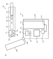
図1は、本発明の一実施形態に係る喫煙システム100の構成図である。図1は喫煙システム100が備える各エレメントを概略的且つ概念的に示すものであり、それら各エレメント及び喫煙システム100の厳密な配置、形状、寸法、位置関係等を示すのではないことに留意されたい。   FIG. 1 is a configuration diagram of a smoking system 100 according to an embodiment of the present invention. It should be noted that FIG. 1 schematically and conceptually shows each element of the smoking system 100 and does not show the exact arrangement, shape, size, positional relationship, etc. of each element and the smoking system 100. I want to.

図1に示されるように、喫煙システム100は、一次装置120及び二次装置140を備える。喫煙システム100は、二次装置140が一次装置120に対して電気的に接続された第1の使用形態と、二次装置140が一次装置120から電気的に切り離された第2の使用形態とをとることができるように構成される。例えば、図1に例示された喫煙システム100において、二次装置140は一次装置120の連結ポート122に挿入されることで一次装置120に対して電気的に接続され、連結ポート122から抜き取られることで一次装置120から電気的に切り離される。別の例として、一次装置120と二次装置140との電気的な接続及び非接続は、例えばUSBケーブルなどの導電性ケーブルの着脱によって行われてもよい。   As shown in FIG. 1, the smoking system 100 includes a primary device 120 and a secondary device 140. The smoking system 100 includes a first usage pattern in which the secondary device 140 is electrically connected to the primary device 120 and a second usage pattern in which the secondary device 140 is electrically disconnected from the primary device 120. Is configured so that For example, in the smoking system 100 illustrated in FIG. 1, the secondary device 140 is electrically connected to the primary device 120 by being inserted into the connection port 122 of the primary device 120, and is extracted from the connection port 122. Is electrically disconnected from the primary device 120. As another example, the electrical connection and disconnection between the primary device 120 and the secondary device 140 may be performed by attaching and detaching a conductive cable such as a USB cable.

二次装置140は、喫煙のためのエアロゾル発生物品160を電気的に加熱することによって香味成分を含んだエアロゾル又は蒸気を発生させる装置である。喫煙者であるユーザは、二次装置140から発生したエアロゾル又は蒸気を吸引することができる。一次装置120は、第1の使用形態において二次装置140に電力を供給するための装置である。第1の使用形態において、一次装置120は、二次装置140に内蔵された二次電源148を充電することができる。二次装置140は、第2の使用形態においては、内蔵された二次電源148によって動作することが可能である。喫煙システム100は、例えば二次電源148が所定量消費された場合に、第2の使用形態から第1の使用形態に戻される。第1の使用形態に戻された時、二次装置140は、一次装置120から電力の供給を受けることにより、二次電源148への再充電が行われるようにすることができるだけでなく、一次装置120から供給される電力を利用して直接的にエアロゾル発生物品160の加熱を行うこともできる。   The secondary device 140 is a device that electrically heats the aerosol-generating article 160 for smoking to generate an aerosol or vapor containing a flavor component. A user who is a smoker can inhale the aerosol or vapor generated from the secondary device 140. The primary device 120 is a device for supplying power to the secondary device 140 in the first usage pattern. In the first usage pattern, the primary device 120 can charge the secondary power source 148 incorporated in the secondary device 140. The secondary device 140 can be operated by the built-in secondary power source 148 in the second usage pattern. The smoking system 100 is returned from the second usage pattern to the first usage pattern when, for example, the secondary power source 148 is consumed by a predetermined amount. When the secondary device 140 is returned to the first usage pattern, the secondary device 140 receives power from the primary device 120 so that the secondary power source 148 can be recharged. It is also possible to directly heat the aerosol-generating article 160 using the electric power supplied from the device 120.

図1に示されるように、二次装置140は、エアロゾル発生物品保持部142、負荷144、駆動回路146、二次電源148、ユーザ操作部152、制御部154、及びメモリ156を備える。二次装置140は、例えば、ユーザがエアロゾル又は蒸気を吸引するのに適した形状と寸法を有するように構成される。ユーザは、例えば二次装置140を指の間に保持して、喫煙を行うことができる。一例として、二次装置140の外形形状は、概略的に、紙巻きたばこに類似の円柱形状であってよいが、これは限定的と解されるべきでなく、任意の他の形状及び寸法をとることもできる。   As shown in FIG. 1, the secondary device 140 includes an aerosol generation article holding unit 142, a load 144, a drive circuit 146, a secondary power supply 148, a user operation unit 152, a control unit 154, and a memory 156. Secondary device 140 is configured, for example, to have a shape and size suitable for a user to inhale aerosols or vapors. The user can smoke, for example, holding the secondary device 140 between his fingers. By way of example, the outer shape of the secondary device 140 may be generally cylindrical, similar to a cigarette, but this should not be construed as limiting and may take any other shape and size. You can also

エアロゾル発生物品保持部142は、エアロゾル発生物品160を保持することができるように構成された空間である。したがって、エアロゾル発生物品保持部142は、エアロゾル発生物品160に応じた形状を有することが可能である。例えば、エアロゾル発生物品160は、紙巻きたばこと同程度の直径の円柱状スティックに成形された固体のエアロゾル基材を含んでよい。図1には、このようなエアロゾル発生物品160がエアロゾル発生物品保持部142に挿入された二次装置140が示されている。エアロゾル基材は、例えば、加熱することによって香喫味成分を放出する刻みたばこ又は粒状若しくは粉末状のたばこ原料を円柱形状に加工し、これに液体のエアロゾル源を添加することによって構成される。な、本実施形態においては、エアロゾル基材及び/又はエアロゾル源が香味源として機能する。図1に示されるように、エアロゾル発生物品160は、その一方の端部及びエアロゾル基材を含む主部がエアロゾル発生物品保持部142の内部に収容され、他方の端部がエアロゾル発生物品保持部142から飛び出した形で、エアロゾル発生物品保持部142に保持される。ユーザは、エアロゾル発生物品160のエアロゾル発生物品保持部142から飛び出した端部を口に咥えることで、喫煙を行うことができる。   The aerosol-generating article holding unit 142 is a space configured to hold the aerosol-generating article 160. Therefore, the aerosol-generating article holding unit 142 can have a shape corresponding to the aerosol-generating article 160. For example, the aerosol-generating article 160 may include a solid aerosol substrate shaped into a cylindrical stick about the same diameter as a cigarette. FIG. 1 shows a secondary device 140 in which such an aerosol-generating article 160 is inserted into an aerosol-generating article holding portion 142. The aerosol base material is constituted, for example, by processing a chopped tobacco or granular or powdery tobacco raw material that releases a flavor component by heating into a cylindrical shape, and adding a liquid aerosol source thereto. However, in the present embodiment, the aerosol base material and / or the aerosol source functions as a flavor source. As shown in FIG. 1, in the aerosol-generating article 160, one end portion and a main portion including the aerosol base material are housed inside the aerosol-generating article holding portion 142, and the other end portion is the aerosol-generating article holding portion. It is held by the aerosol-generating article holding unit 142 in a form protruding from the 142. The user can smoke by holding the end of the aerosol-generating article 160, which is protruding from the aerosol-generating article holding portion 142, in his mouth.

なお、使い勝手を考慮すると二次装置140は、既存の紙巻きたばこに近い形状に構成されることが好ましい。また、二次装置140は空洞状のエアロゾル発生物品保持部142を有しているため、二次装置140の内部において電装品の配置には制約が加わる。その結果、二次電源148も小型のものが好ましく、その容量も比較的小さくなってしまう。一方、一次装置120はこのような制約がないため、二次電源148を複数回充電できるように、一次電源126は二次電源148と比べて十分に大きな容量を有していることが好ましい。例えば、一次電源126は二次電源148と比べて5〜40倍の容量を有していることが好ましいが、この範囲に限定されるものではない。また、一次電源126と二次電源148は共にリチウムイオン二次電池から構成されることが好ましいが、これに限定されるものではない。   Note that, in consideration of usability, the secondary device 140 is preferably configured to have a shape similar to that of an existing cigarette. Further, since the secondary device 140 has the hollow aerosol-generated article holding portion 142, restrictions are placed on the arrangement of electrical components inside the secondary device 140. As a result, it is preferable that the secondary power source 148 is also small, and the capacity thereof is relatively small. On the other hand, since the primary device 120 does not have such a limitation, it is preferable that the primary power source 126 has a sufficiently large capacity as compared with the secondary power source 148 so that the secondary power source 148 can be charged multiple times. For example, the primary power source 126 preferably has a capacity that is 5 to 40 times that of the secondary power source 148, but is not limited to this range. Further, both the primary power source 126 and the secondary power source 148 are preferably composed of lithium ion secondary batteries, but are not limited thereto.

エアロゾル発生物品160及びエアロゾル発生物品保持部142は、図1に示されるのとは異なるように構成されてもよい。例えば、エアロゾル発生物品160は、香味成分(香味源)を含有した液体状のエアロゾル源であってもよい。一例として、香味成分(香味源)を含有した液体状のエアロゾル源は、ニコチン成分を含有したグリセリン又はプロピレングリコール等のポリオールである。本実施形態においては、エアロゾル源が香味源として機能する。エアロゾル発生物品160が香味成分(香味源)を含有したエアロゾル源である場合、エアロゾル発生物品保持部142は、例えば、ガラス繊維や多孔質セラミック等の繊維状又は多孔質性の素材から構成され、繊維間の隙間や多孔質材料の細孔に液体としてのエアロゾル源を保持する。あるいは、エアロゾル発生物品保持部142は、液体を収容するタンクとして構成されてもよい。このような構成において、二次装置140は、付加的に吸口部材を備える。ユーザは、吸口部材を口に咥えることで、発生したエアロゾル又は蒸気を吸引することができる。   The aerosol-generating article 160 and the aerosol-generating article holder 142 may be configured differently than that shown in FIG. For example, the aerosol-generating article 160 may be a liquid aerosol source containing a flavor component (flavor source). As an example, the liquid aerosol source containing a flavor component (flavor source) is a polyol such as glycerin or propylene glycol containing a nicotine component. In this embodiment, the aerosol source functions as a flavor source. When the aerosol-generating article 160 is an aerosol source containing a flavor component (flavor source), the aerosol-generating article holding unit 142 is made of, for example, a fibrous or porous material such as glass fiber or porous ceramic, The aerosol source as a liquid is held in the spaces between the fibers or in the pores of the porous material. Alternatively, the aerosol-generating article holding unit 142 may be configured as a tank that stores a liquid. In such a configuration, the secondary device 140 additionally includes a suction member. The user can suck the generated aerosol or vapor by holding the mouthpiece member in his mouth.

負荷144は、エアロゾル発生物品保持部142に保持されたエアロゾル発生物品160を電気的に加熱するための加熱素子である。負荷144は、エアロゾル発生物品160を加熱することができるように、エアロゾル発生物品160に接して、又はエアロゾル発生物品160の近傍に配置される。負荷144は、二次装置140が一次装置120から切り離された第2の使用形態においては、二次装置140に内蔵された二次電源148から給電されることにより、エアロゾル発生物品160を加熱する。また負荷144は、二次装置140が一次装置120に接続された第1の使用形態においては、一次装置120から給電されることによりエアロゾル発生物品160を加熱する。なお、エアロゾル発生物品160がエアロゾル源及びエアロゾル基材を含む場合は、上述したようにエアロゾル発生物品160を負荷144で加熱することで、エアロゾル源を昇温し、エアロゾルを発生させる。一方、エアロゾル発生物品160が香味成分(香味源)を含有した液体状のエアロゾル源である場合は、エアロゾル源を負荷144で直接加熱することで、エアロゾルを発生させてもよい。   The load 144 is a heating element for electrically heating the aerosol-generating article 160 held by the aerosol-generating article holding portion 142. The load 144 is placed in contact with or near the aerosol-generating article 160 so that the aerosol-generating article 160 can be heated. In the second usage pattern in which the secondary device 140 is separated from the primary device 120, the load 144 heats the aerosol-generating article 160 by being supplied with power from the secondary power source 148 incorporated in the secondary device 140. . In the first usage pattern in which the secondary device 140 is connected to the primary device 120, the load 144 heats the aerosol-generating article 160 by being supplied with power from the primary device 120. When the aerosol-generating article 160 includes an aerosol source and an aerosol base material, the aerosol-generating article 160 is heated by the load 144 to heat the aerosol source and generate an aerosol as described above. On the other hand, when the aerosol-generating article 160 is a liquid aerosol source containing a flavor component (flavor source), the aerosol may be generated by directly heating the aerosol source with the load 144.

負荷144とエアロゾル発生物品160を接触させるための任意の配置が用いられてよい。一例として、負荷144は、エアロゾル発生物品保持部142の内壁の表面に露出するように配置されるのであってよい。この配置によれば、エアロゾル発生物品保持部142へ挿入されたエアロゾル発生物品160は、その外周表面(例えば円柱状スティックの側面)において負荷144と接触するので、エアロゾル発生物品160を外周から加熱することができる。また別の例として、エアロゾル発生物品保持部142へエアロゾル発生物品160が挿入された時に負荷144が(例えばエアロゾル基材を突き刺すことによって)エアロゾル基材の中へ入り込むのであってもよい。このような構成によれば、負荷144はエアロゾル発生物品160をその内部から加熱することができる。なお、負荷144は、エアロゾル発生物品160と直接接触するのではなく、エアロゾル発生物品160を加熱することができる程度にエアロゾル発生物品160の近傍に配置されるのであってもよい。   Any arrangement for contacting the load 144 and the aerosol-generating article 160 may be used. As an example, the load 144 may be arranged so as to be exposed on the surface of the inner wall of the aerosol-generating article holding portion 142. According to this arrangement, the aerosol-generating article 160 inserted into the aerosol-generating article holding portion 142 contacts the load 144 on the outer peripheral surface (for example, the side surface of the cylindrical stick), so that the aerosol-generating article 160 is heated from the outer periphery. be able to. As another example, the load 144 may penetrate into the aerosol substrate (eg, by piercing the aerosol substrate) when the aerosol-generating article 160 is inserted into the aerosol-generating article holding portion 142. With such a configuration, the load 144 can heat the aerosol-generating article 160 from the inside. It should be noted that the load 144 may be arranged in the vicinity of the aerosol-generating article 160 to the extent that the aerosol-generating article 160 can be heated, rather than being in direct contact with the aerosol-generating article 160.

二次電源148は、第2の使用形態において二次装置140を動作させるのに用いられる電源である。二次電源148は、駆動回路146を介して負荷144へ給電することが可能である。負荷144への給電により二次電源148の残容量は減少するが、二次電源148は、第1の使用形態において一次装置120によって充電されることで、残容量を回復することができる。   The secondary power source 148 is a power source used to operate the secondary device 140 in the second usage pattern. The secondary power source 148 can supply power to the load 144 via the driving circuit 146. The remaining capacity of the secondary power supply 148 is reduced by supplying power to the load 144, but the secondary power supply 148 can recover the remaining capacity by being charged by the primary device 120 in the first usage pattern.

ユーザ操作部152は、ユーザから二次装置140に対する操作を受け付けることができるように構成される。二次装置140に対するユーザ操作は、例えば、二次装置140を起動するための起動指示、及び負荷144への給電を実行するための給電指示を含む。ユーザ操作部152は、起動指示を入力するための起動指示部と給電指示を入力するための給電指示部とを別個に備えてもよいし、起動指示と給電指示の両方を受け付け可能な1つの指示部を備えるのであってもよい。一例として、ユーザ操作部152は、ユーザが物理的に操作することが可能なボタン、スイッチ、ツマミ、レバー、タッチセンサ等として構成される。   The user operation unit 152 is configured to be able to receive an operation on the secondary device 140 from the user. The user operation on the secondary device 140 includes, for example, an activation instruction for activating the secondary device 140 and a power supply instruction for executing power supply to the load 144. The user operation unit 152 may separately include a start instruction unit for inputting a start instruction and a power supply instruction unit for inputting a power supply instruction, or one user operation unit that can accept both the start instruction and the power supply instruction. An instruction unit may be provided. As an example, the user operation unit 152 is configured as a button, a switch, a knob, a lever, a touch sensor or the like that can be physically operated by the user.

制御部154は、マイクロプロセッサ又はマイクロコンピュータとして構成された電子回路モジュールであり、メモリ156に格納されたコンピュータ実行可能命令に従って二次装置140の動作を制御するようにプログラムされる。メモリ156は、ROM、RAM、フラッシュメモリなどの情報記憶媒体である。メモリ156には、コンピュータ実行可能命令のほか、二次装置140の制御に必要な設定データが格納される。   The controller 154 is an electronic circuit module configured as a microprocessor or a microcomputer, and is programmed to control the operation of the secondary device 140 according to computer-executable instructions stored in the memory 156. The memory 156 is an information storage medium such as a ROM, a RAM, and a flash memory. The memory 156 stores computer-executable instructions and setting data necessary for controlling the secondary device 140.

図1及び図2を参照して、一次装置120は、連結ポート122、給電回路124、一次電源126、ユーザ操作部132、制御部134、及びメモリ136を備える。一次装置120のこれら各エレメントは、例えば、一次装置120の本体部120Aに備えられている。一次装置120は更に、図1においては蓋として描かれている拘束部120Bを備える。図1に示されるように、蓋120Bは、ヒンジ120Cにより本体部120Aに係合されて本体部120Aの上部に取り付けられており、本体部120Aを開閉することができる。図1には、蓋120Bを開かれた状態の一次装置120が示されている。蓋120Bは、閉じられた状態にある時、連結ポート122に挿入された二次装置140が連結ポート122から脱落しないように、二次装置140を拘束する。蓋120Bは、スライド開閉式の蓋であってもよい。また、拘束部120Bは、蓋としての形態ではなく、二次装置140の動きを拘束可能な他の部材(例えば、ツメを二次装置140に係合させる構造や、磁石による吸着を利用した構造など)によって構成されてもよい。   1 and 2, the primary device 120 includes a connection port 122, a power feeding circuit 124, a primary power source 126, a user operation unit 132, a control unit 134, and a memory 136. Each of these elements of the primary device 120 is provided in the main body 120A of the primary device 120, for example. Primary device 120 further comprises a restraint 120B, depicted in FIG. 1 as a lid. As shown in FIG. 1, the lid 120B is attached to the upper portion of the main body 120A by being engaged with the main body 120A by the hinge 120C, and the main body 120A can be opened and closed. FIG. 1 shows the primary device 120 with the lid 120B opened. The lid 120B restrains the secondary device 140 so that the secondary device 140 inserted in the coupling port 122 does not drop out from the coupling port 122 when in the closed state. The lid 120B may be a slide opening / closing type lid. Further, the restraint part 120B is not a form as a lid, but another member capable of restraining the movement of the secondary device 140 (for example, a structure in which a claw is engaged with the secondary device 140, or a structure utilizing attraction by a magnet). Etc.).

連結ポート122は、喫煙システム100の第1の使用形態において二次装置140を収容するための空間である。連結ポート122に二次装置140が挿入されると、二次装置140の接続端子146−1が、連結ポート122内に配置された一次装置120側の接続端子124−2と接触する。接続端子146−1は二次装置140の駆動回路146の一部をなす端子であり、接続端子124−2は一次装置120の給電回路124の一部をなす端子である。これにより、二次装置140が一次装置120に対して電気的に接続される。   The connection port 122 is a space for housing the secondary device 140 in the first usage pattern of the smoking system 100. When the secondary device 140 is inserted into the connection port 122, the connection terminal 146-1 of the secondary device 140 comes into contact with the connection terminal 124-2 on the primary device 120 side arranged in the connection port 122. The connection terminal 146-1 is a terminal forming a part of the drive circuit 146 of the secondary device 140, and the connection terminal 124-2 is a terminal forming a part of the power supply circuit 124 of the primary device 120. As a result, the secondary device 140 is electrically connected to the primary device 120.

一次電源126は、第1の使用形態において二次装置140へ電力を供給するのに用いられる電源である。一次電源126は、第1の使用形態において喫煙システム100が後述する充電モードで駆動される場合、給電回路124及び駆動回路146を介して二次装置140の二次電源148を充電する。一次電源126はまた、第1の使用形態において喫煙システム100が後述する直接加熱モードで駆動される場合には、給電回路124及び駆動回路146を介して二次装置140の負荷144へ給電することが可能である。これにより、二次装置140の負荷144は、二次装置140に内蔵された二次電源148の残容量が回復するのを待つことなく、二次装置140が連結ポート122に挿入されると直ちに、一次電源126から給電を受けることで、エアロゾル発生物品160の加熱を行うことができる。二次装置140への給電によって一次電源126の残容量は減少するが、一次電源126は、外部接続端子(不図示)を介して外部の充電装置(不図示)によって充電されることで、残容量を回復することができる。   The primary power source 126 is a power source used to supply power to the secondary device 140 in the first usage pattern. The primary power source 126 charges the secondary power source 148 of the secondary device 140 via the power feeding circuit 124 and the driving circuit 146 when the smoking system 100 is driven in the charging mode described below in the first usage pattern. The primary power supply 126 also supplies power to the load 144 of the secondary device 140 via the power supply circuit 124 and the drive circuit 146 when the smoking system 100 is driven in the direct heating mode described below in the first usage pattern. Is possible. As a result, the load 144 of the secondary device 140 does not wait for the remaining capacity of the secondary power source 148 incorporated in the secondary device 140 to recover, and immediately after the secondary device 140 is inserted into the connection port 122. By receiving power from the primary power source 126, the aerosol-generating article 160 can be heated. Although the remaining capacity of the primary power source 126 is reduced by supplying power to the secondary device 140, the primary power source 126 is charged by an external charging device (not shown) via an external connection terminal (not shown), and thus the remaining capacity is reduced. Capacity can be restored.

ユーザ操作部132は、ユーザから一次装置120に対する操作を受け付けることができるように構成される。一次装置120に対するユーザ操作は、例えば、二次装置140への給電を許可するための動作指示を含む。一例として、ユーザ操作部132は、ユーザが物理的に操作することが可能なボタン、スイッチ、ツマミ、レバー、タッチセンサ等として構成される。   The user operation unit 132 is configured to be able to receive an operation on the primary device 120 from the user. The user operation on the primary device 120 includes, for example, an operation instruction for permitting power supply to the secondary device 140. As an example, the user operation unit 132 is configured as a button, a switch, a knob, a lever, a touch sensor or the like that can be physically operated by the user.

制御部134は、マイクロプロセッサ又はマイクロコンピュータとして構成された電子回路モジュールであり、メモリ136に格納されたコンピュータ実行可能命令に従って一次装置120の動作を制御するようにプログラムされる。メモリ136は、ROM、RAM、フラッシュメモリなどの情報記憶媒体である。メモリ136には、コンピュータ実行可能命令のほか、一次装置120の制御に必要な設定データが格納される。   The controller 134 is an electronic circuit module configured as a microprocessor or a microcomputer, and is programmed to control the operation of the primary device 120 according to computer-executable instructions stored in the memory 136. The memory 136 is an information storage medium such as a ROM, a RAM, or a flash memory. The memory 136 stores computer-executable instructions as well as configuration data required to control the primary device 120.

図2は、本発明の一実施形態に係る喫煙システム100の電気回路図を示す。図2に示されるように、喫煙システム100の電気回路200は、一次装置120の給電回路124及び二次装置140の駆動回路146を含む。一次装置120の給電回路124は、DC/DCコンバータ124−1及び接続端子124−2を備える。DC/DCコンバータ124−1は、制御部(一次装置120の制御部134及び/又は二次装置140の制御部154)による制御に従って一次電源126の電圧を昇圧又は降圧し、それにより一次装置120の出力電圧を調整する。また、一般的にDC/DCコンバータは、出力電圧を制御する電圧制御モードと、出力電流(電力)を制御する電流(電力)モードを有しているため、DC/DCコンバータ124−1は、一次装置120の出力電流(電力)を調整してもよい。二次装置140の駆動回路146は、第1スイッチSW1、第2スイッチSW2、第3スイッチSW3、第4スイッチSW4、及び接続端子146−1を備える。各スイッチSW1、SW2、SW3、SW4は、例えばトランジスタ等の電気的スイッチであり、制御部(二次装置140の制御部154及び/又は一次装置120の制御部134)によってオン状態とオフ状態をそれぞれ個別に切り替えるように制御される。電気回路200は、一次装置120の連結ポート122に挿入された二次装置140が二次装置140側の接続端子146−1と一次装置120側の接続端子124−2を介して一次装置120と電気的に接続されることによって構成されている。   FIG. 2 shows an electric circuit diagram of a smoking system 100 according to an embodiment of the present invention. As shown in FIG. 2, the electric circuit 200 of the smoking system 100 includes a power supply circuit 124 of the primary device 120 and a drive circuit 146 of the secondary device 140. The power supply circuit 124 of the primary device 120 includes a DC / DC converter 124-1 and a connection terminal 124-2. The DC / DC converter 124-1 boosts or lowers the voltage of the primary power source 126 according to the control by the control unit (the control unit 134 of the primary device 120 and / or the control unit 154 of the secondary device 140), and thereby the primary device 120. Adjust the output voltage of. Further, since the DC / DC converter generally has a voltage control mode for controlling the output voltage and a current (power) mode for controlling the output current (power), the DC / DC converter 124-1 is The output current (power) of the primary device 120 may be adjusted. The drive circuit 146 of the secondary device 140 includes a first switch SW1, a second switch SW2, a third switch SW3, a fourth switch SW4, and a connection terminal 146-1. Each of the switches SW1, SW2, SW3, and SW4 is an electrical switch such as a transistor, and is turned on and off by a control unit (the control unit 154 of the secondary device 140 and / or the control unit 134 of the primary device 120). It is controlled to switch each individually. In the electric circuit 200, the secondary device 140 inserted into the connection port 122 of the primary device 120 is connected to the primary device 120 via the connection terminal 146-1 on the secondary device 140 side and the connection terminal 124-2 on the primary device 120 side. It is configured by being electrically connected.

図3は、本発明の一実施形態に係る喫煙システム100の複数の動作モードに対する電気回路200の状態遷移300を示す。喫煙システム100は、通常喫煙モード、通常非喫煙モード、充電モード、及び直接加熱モードの4つのモードで動作することが可能である。通常喫煙モードは、二次装置140を一次装置120から電気的に切り離して単独で動作させることにより喫煙を行うモードである。通常非喫煙モードは、二次装置140を一次装置120から切り離したまま喫煙を停止するモードである。充電モードは、二次装置140を一次装置120に接続して一次装置120の一次電源126から二次装置140の二次電源148への充電を行うモードである。直接加熱モードは、二次装置140を一次装置120に接続して一次装置120の一次電源126から二次装置140の負荷144への直接的な給電を行うことにより、喫煙を行うモードである。通常喫煙モードと通常非喫煙モードは、第2の使用形態に対応し、充電モードと直接加熱モードは、第1の使用形態に対応する。   FIG. 3 illustrates state transitions 300 of the electrical circuit 200 for multiple operating modes of the smoking system 100 according to one embodiment of the invention. The smoking system 100 is capable of operating in four modes: normal smoking mode, normal non-smoking mode, charging mode, and direct heating mode. The normal smoking mode is a mode for smoking by electrically disconnecting the secondary device 140 from the primary device 120 and operating the device independently. The normal non-smoking mode is a mode in which smoking is stopped while the secondary device 140 is disconnected from the primary device 120. The charging mode is a mode in which the secondary device 140 is connected to the primary device 120 and the primary power source 126 of the primary device 120 charges the secondary power source 148 of the secondary device 140. The direct heating mode is a mode in which smoking is performed by connecting the secondary device 140 to the primary device 120 and directly supplying power from the primary power source 126 of the primary device 120 to the load 144 of the secondary device 140. The normal smoking mode and the normal non-smoking mode correspond to the second usage pattern, and the charging mode and the direct heating mode correspond to the first usage pattern.

図3に示されるように、通常喫煙モードにおいて、制御部は、第1スイッチSW1、第2スイッチSW2、及び第4スイッチSW4をオン状態に設定し、第3スイッチSW3をオフ状態に設定する。これにより、二次装置140の二次電源148から負荷144への給電が行われて、エアロゾル発生物品160が負荷144により加熱される。したがって、ユーザは第2の使用形態において喫煙を行うことができる。また制御部は、通常非喫煙モードにおいて、全てのスイッチSW1、SW2、SW3、SW4をオフ状態に設定する。これにより、負荷144への給電が遮断されて、エアロゾル発生物品160の加熱が停止される。充電モードでは、制御部は、第3スイッチSW3をオン状態に設定し、第1スイッチSW1、第2スイッチSW2、及び第4スイッチSW4をオフ状態に設定する。これにより、一次装置120の一次電源126から二次装置140の二次電源148への給電が行われて、二次電源148が充電される。一方、直接加熱モードにおいて、制御部は、第1スイッチSW1及び第2スイッチSW2をオン状態に設定し、第3スイッチSW3及び第4スイッチSW4をオフ状態に設定する。これにより、一次装置120の一次電源126から負荷144への直接的な給電が行われて、エアロゾル発生物品160が負荷144により加熱される。したがって、第1の使用形態においてもユーザは喫煙を行うことができる。   As shown in FIG. 3, in the normal smoking mode, the control unit sets the first switch SW1, the second switch SW2, and the fourth switch SW4 to the on state, and sets the third switch SW3 to the off state. As a result, power is supplied from the secondary power source 148 of the secondary device 140 to the load 144, and the aerosol-generating article 160 is heated by the load 144. Therefore, the user can smoke in the second usage pattern. Further, the control unit sets all the switches SW1, SW2, SW3, and SW4 to the off state in the normal non-smoking mode. As a result, the power supply to the load 144 is cut off, and the heating of the aerosol-generating article 160 is stopped. In the charging mode, the control unit sets the third switch SW3 to the ON state and sets the first switch SW1, the second switch SW2, and the fourth switch SW4 to the OFF state. As a result, power is supplied from the primary power source 126 of the primary device 120 to the secondary power source 148 of the secondary device 140, and the secondary power source 148 is charged. On the other hand, in the direct heating mode, the control unit sets the first switch SW1 and the second switch SW2 to the ON state, and sets the third switch SW3 and the fourth switch SW4 to the OFF state. As a result, the primary power supply 126 of the primary device 120 directly supplies power to the load 144, and the aerosol-generating article 160 is heated by the load 144. Therefore, the user can smoke in the first usage pattern.

このように、喫煙システム100は、二次装置140の駆動回路146が備える各スイッチのオン状態とオフ状態を制御することで動作モードを切り替えることができる。喫煙システム100は更に、二次装置140が一次装置120に接続された第1の使用形態において、充電モードと直接加熱モードとの間でモードを切り替える際には、充電モードから直ちに直接加熱モードへ、あるいは直接加熱モードから直ちに充電モードへ移行するのではなく、その途中に遷移モードを実行するように構成される。即ち、喫煙システム100の第1の使用形態における動作モードの切り替えは、充電モードから遷移モードを経由して直接加熱モードへ移行することにより、又は直接加熱モードから遷移モードを経由して充電モードへ移行することにより行われる。充電モードから直接加熱モードへ移行する方向と直接加熱モードから充電モードへ移行する方向の双方において遷移モードが介在してもよいし、あるいはいずれか一方の方向においてのみ遷移モードが介在するのであってもよい。   As described above, the smoking system 100 can switch the operation mode by controlling the on state and the off state of each switch included in the drive circuit 146 of the secondary device 140. The smoking system 100 further includes, when switching the mode between the charging mode and the direct heating mode in the first usage mode in which the secondary device 140 is connected to the primary device 120, immediately switches from the charging mode to the direct heating mode. Alternatively, the transition mode is executed during the transition from the direct heating mode to the charging mode immediately. That is, the switching of the operation mode in the first usage pattern of the smoking system 100 is performed by shifting from the charging mode to the direct heating mode via the transition mode, or from the direct heating mode to the charging mode via the transition mode. It is done by shifting. The transition mode may intervene both in the direction from the charging mode to the direct heating mode and in the direction from the direct heating mode to the charging mode, or the transition mode may intervene in only one direction. Good.

遷移モードは、一次装置120から二次装置140への給電に関する変数を変更する処理を行うモードである。給電に関する変数は、非限定的な例として、一次装置120から二次装置140への給電量(即ち一次装置120の一次電源126からの放電レート)を含む。例えば、給電対象の特性や用途に応じて、給電量(レート)は適切な値とすることが好ましいため、充電モードにおける一次装置120から二次装置140への給電量は、直接加熱モードにおける一次装置120から二次装置140への給電量と異なっている。   The transition mode is a mode for performing a process of changing a variable relating to power feeding from the primary device 120 to the secondary device 140. The variable relating to the power supply includes, as a non-limiting example, the amount of power supply from the primary device 120 to the secondary device 140 (that is, the discharge rate from the primary power source 126 of the primary device 120). For example, since it is preferable to set the power supply amount (rate) to an appropriate value according to the characteristics and application of the power supply target, the power supply amount from the primary device 120 to the secondary device 140 in the charging mode is the primary power in the direct heating mode. The amount of power supply from the device 120 to the secondary device 140 is different.

例えば、二次装置140の二次電源148としてリチウムイオン二次電池を用いた場合、電極、電解液、活物質、又は導電助剤といった材料やその構造によって差異はあるものの、リチウムイオン二次電池はレート依存性という性質を有する。このレート依存性とは、充電レートまたは放電レートの大きさと、リチウムイオン二次電池の劣化に及ぼす影響との相関関係を指す。なお、ここでいうリチウムイオン二次電池の劣化とは、例えば新品時(工場出荷時)の充電可能容量または放電可能容量に対する、現在の充電可能容量または放電可能容量の比によって表される。一般的な傾向として、レートが大きくなるほど、リチウムイオン二次電池の劣化に及ぼす影響が加速度的に大きくなる。また、同じレートであっても、放電が劣化に及ぼす影響に比べ、充電が劣化に及ぼす影響の方が2〜3倍程度大きい。従って、充電モードにおける一次装置120から二次装置140への給電量は、充電される二次電源140の劣化を抑制するために比較的小さな値に制御されることが好ましい。   For example, when a lithium-ion secondary battery is used as the secondary power source 148 of the secondary device 140, the lithium-ion secondary battery varies depending on the materials such as electrodes, electrolytic solution, active material, or conductive auxiliary agent and its structure. Has the property of rate dependence. The rate dependency refers to a correlation between the magnitude of the charge rate or the discharge rate and the influence on the deterioration of the lithium ion secondary battery. The term "deterioration of the lithium ion secondary battery" as used herein is represented by, for example, the ratio of the current chargeable capacity or dischargeable capacity to the chargeable capacity or dischargeable capacity at the time of new product (factory shipment). As a general tendency, as the rate increases, the influence on the deterioration of the lithium-ion secondary battery increases at an accelerating rate. Further, even at the same rate, the effect of charging on deterioration is about 2-3 times larger than the effect of discharging on deterioration. Therefore, the amount of power supplied from the primary device 120 to the secondary device 140 in the charging mode is preferably controlled to a relatively small value in order to suppress deterioration of the secondary power source 140 to be charged.

一方の直接加熱モードでは、一次電源126から主に負荷144への給電を行うので、上述したような二次電源140の劣化抑制に配慮した制約は存在しない。むしろエアロゾルが生成される温度までエアロゾル発生物品160を加熱する必要があるため、直接加熱モードにおける一次装置120から二次装置140への給電量は、比較的大きな値に制御されることが好ましい。より詳細に検討するならば、一次装置120の一次電源126にもリチウムイオン二次電池を用いた場合、一次装置120から二次装置140への給電量を大きな値に制御すると、一次電源126自体の有するレート依存性によって一次電源126に劣化が生じるのか否かが懸念される。ここで、一次電源126は、上述したように二次電源148を複数回充電できるように二次電源148と比べて十分に大きな容量を有していることが好ましいが、広く知られているように、一般に二次電池は容量が大きいほどレートは小さくなる。また、一次電源126は二次装置140に対して放電を行うが、上述したように、放電は充電と比較して劣化に及ぼす影響が小さい。したがって、一次装置120から二次装置140への給電量を大きな値に制御しても、これを適切な範囲に調整すれば一次電源126の劣化は十分に抑制できる。   On the other hand, in the direct heating mode, power is mainly supplied from the primary power source 126 to the load 144, so that there is no restriction considering the suppression of deterioration of the secondary power source 140 as described above. Rather, since it is necessary to heat the aerosol-generating article 160 to a temperature at which the aerosol is generated, the power supply amount from the primary device 120 to the secondary device 140 in the direct heating mode is preferably controlled to a relatively large value. In more detail, when a lithium ion secondary battery is also used as the primary power source 126 of the primary device 120, if the power supply amount from the primary device 120 to the secondary device 140 is controlled to a large value, the primary power source 126 itself. There is concern about whether or not the primary power supply 126 is deteriorated due to the rate dependence of the. Here, it is preferable that the primary power source 126 has a sufficiently large capacity as compared with the secondary power source 148 so that the secondary power source 148 can be charged a plurality of times as described above, but it is widely known. In general, the rate of the secondary battery decreases as the capacity increases. Further, the primary power source 126 discharges the secondary device 140, but as described above, the discharge has a smaller influence on the deterioration than the charging. Therefore, even if the power supply amount from the primary device 120 to the secondary device 140 is controlled to a large value, the deterioration of the primary power supply 126 can be sufficiently suppressed by adjusting this to an appropriate range.

このような充電モードと直接加熱モードにおける一次装置120から二次装置140への給電量の差を埋めるために、喫煙システム100は、遷移モードにおいて、一次装置120から二次装置140への給電量を、動作モード切り替え前のモード(充電モードと直接加熱モードの一方)の給電量から切り替え後のモード(充電モードと直接加熱モードの他方)の給電量へと変更する処理を実行する。給電量の変更は、例えば、一次装置120のDC/DCコンバータ124−1からの出力電圧や出力電流(電力)を制御することによって実現される。このように遷移モードにおいて喫煙システム100が給電量の変更処理を実施することにより、第1の使用形態における充電モードと直接加熱モードとの切り替えを円滑に行うことができる。   In order to fill the difference in the amount of power supply from the primary device 120 to the secondary device 140 in the charging mode and the direct heating mode, the smoking system 100 uses the amount of power supply from the primary device 120 to the secondary device 140 in the transition mode. Is performed from the power supply amount in the mode before switching the operation mode (one of the charging mode and the direct heating mode) to the power supply amount in the mode after switching (the other of the charging mode and the direct heating mode). The change of the power supply amount is realized by controlling the output voltage or output current (power) from the DC / DC converter 124-1 of the primary device 120, for example. In this way, smoking system 100 performs the power supply amount changing process in the transition mode, so that the switching between the charging mode and the direct heating mode in the first usage pattern can be smoothly performed.

遷移モードが持続する時間(以下、遷移時間と称する)の長さは、様々な値に設定されてよい。例えば、動作モードを直接加熱モードから充電モードへ切り替える場合の遷移時間は、単に、一次装置120のDC/DCコンバータ124−1が出力電圧や出力電流(電圧)を変更するのに要する時間に設定されてよい。この時間の長さは、DC/DCコンバータ124−1の電気的な処理にのみ依存し、典型的には1秒未満であり得る。また例えば、動作モードを充電モードから直接加熱モードへ切り替える場合には、遷移モードは、DC/DCコンバータ124−1によって電圧が変更された後、更に、ユーザが喫煙開始の準備としてエアロゾル発生物品160を二次装置140のエアロゾル発生物品保持部142に挿入するまで延期されてもよい。この場合の遷移時間は、ユーザの人為的操作を待つ必要があるため、典型的には1秒より長く、例えば数秒から数十秒であると想定される。   The length of time that the transition mode lasts (hereinafter, referred to as transition time) may be set to various values. For example, the transition time when switching the operation mode from the direct heating mode to the charging mode is simply set to the time required for the DC / DC converter 124-1 of the primary device 120 to change the output voltage or the output current (voltage). May be done. This length of time depends only on the electrical processing of the DC / DC converter 124-1 and may typically be less than 1 second. Further, for example, in the case of switching the operation mode from the charging mode to the direct heating mode, the transition mode is further changed after the voltage is changed by the DC / DC converter 124-1 and then the user further prepares to start smoking the aerosol-generating article 160. May be postponed until it is inserted into the aerosol-generating article holding portion 142 of the secondary device 140. The transition time in this case is typically longer than 1 second, for example, several seconds to several tens of seconds because it is necessary to wait for a user's artificial operation.

図4Aは、直接加熱モードから充電モードへの切り替え時における喫煙システム100の状態の推移の一例を示すタイミングチャートである。図4Aを参照すると、喫煙システム100は、初めに直接加熱モードで動作している。上述したように、直接加熱モードにおいて制御部は、二次装置140の駆動回路146の第1スイッチSW1及び第2スイッチSW2をオン状態に、第3スイッチSW3をオフ状態にそれぞれ設定する。また制御部は、一次装置120の給電回路124のDC/DCコンバータ124−1を制御することによって、エアロゾル発生物品160が所定の目標温度に加熱又は保持されるように一次装置120から二次装置140の負荷144への給電量を調整する。   FIG. 4A is a timing chart showing an example of transition of the state of the smoking system 100 when switching from the direct heating mode to the charging mode. Referring to FIG. 4A, smoking system 100 is initially operating in the direct heating mode. As described above, in the direct heating mode, the control unit sets the first switch SW1 and the second switch SW2 of the drive circuit 146 of the secondary device 140 to the on state and the third switch SW3 to the off state, respectively. In addition, the control unit controls the DC / DC converter 124-1 of the power supply circuit 124 of the primary device 120 so that the aerosol-generating article 160 is heated or held at a predetermined target temperature from the primary device 120 to the secondary device. The amount of power supply to the load 144 of 140 is adjusted.

喫煙システム100は次に、例えば所定のユーザ操作がユーザ操作部132又は152に入力されたことを契機として、遷移モードへ移行する。例えば、ユーザは、喫煙システム100を直接加熱モードから充電モードへ切り替える指示を、ユーザ操作部132又は152を介して入力する。制御部は、このようなユーザ操作を受けると、二次装置140の駆動回路146の第1スイッチSW1及び第2スイッチSW2をオン状態からオフ状態に変更すると共に、第3スイッチSW3をそのままオフ状態に維持することによって、喫煙システム100を遷移モードへ移行させる。制御部はまた、遷移モードにおいて、一次装置120のDC/DCコンバータ124−1を制御することにより、一次装置120から二次装置140への給電量を直接加熱モード用の給電量から充電モード用の給電量へ変更する。前述したように、一般に充電池(二次電源148)の充電時に許容される最大の給電量(充電レート)は、ヒータ(負荷144)の加熱に必要な給電量よりも小さい。最大許容レートよりも大きいレートで充電が行われると、二次電源148の性能が劣化するおそれがある。したがって制御部は、一次装置120からの給電量が直接加熱モード用の高い給電量から充電モード用の低い給電量へと減少するように、DC/DCコンバータ124−1を制御する。給電量が下がりきるには有限の時間(例えば1秒未満)がかかるが、図4Aの遷移モードでは二次装置140の駆動回路146の第3スイッチSW3がオフ状態に設定されるため、充電モード用の低い給電量へ下がりきる前の比較的高い給電量によって二次装置140の二次電源148が充電されてしまうことを回避することができる。また、給電量が充電モード用の低い給電量へ下がるのにかかる時間はごく短いので、実質上、直接加熱モードから充電モードへの素早い切り替えを実現できる。   Next, the smoking system 100 shifts to the transition mode, for example, when a predetermined user operation is input to the user operation unit 132 or 152. For example, the user inputs an instruction to switch the smoking system 100 from the direct heating mode to the charging mode via the user operation unit 132 or 152. Upon receiving such a user operation, the control unit changes the first switch SW1 and the second switch SW2 of the drive circuit 146 of the secondary device 140 from the ON state to the OFF state, and the third switch SW3 as it is in the OFF state. By keeping the smoking system 100 in the transition mode. In the transition mode, the control unit also controls the DC / DC converter 124-1 of the primary device 120 to change the power supply amount from the primary device 120 to the secondary device 140 from the power supply amount for the direct heating mode to the charge mode. Change to the power supply amount of. As described above, generally, the maximum power supply amount (charge rate) allowed when charging the rechargeable battery (secondary power source 148) is smaller than the power supply amount required for heating the heater (load 144). If the charging is performed at a rate higher than the maximum allowable rate, the performance of the secondary power supply 148 may deteriorate. Therefore, the control unit controls the DC / DC converter 124-1 so that the power supply amount from the primary device 120 decreases from the high power supply amount for the direct heating mode to the low power supply amount for the charging mode. It takes a finite time (for example, less than 1 second) for the power supply amount to be completely reduced, but in the transition mode of FIG. It is possible to prevent the secondary power supply 148 of the secondary device 140 from being charged by the relatively high power supply amount before the power supply is reduced to a low power supply amount. Moreover, since the time taken for the power supply amount to fall to the low power supply amount for the charging mode is very short, it is possible to substantially realize the quick switching from the direct heating mode to the charging mode.

所定の長さの遷移時間が経過すると、喫煙システム100は遷移モードから充電モードへ移行する。充電モードにおいて、制御部は、二次装置140の駆動回路146の第1スイッチSW1及び第2スイッチSW2を引き続き遷移モードと同じオフ状態に保持すると共に、第3スイッチSW3をオフ状態からオン状態に変更する。これにより、一次装置120から二次装置140の二次電源148へ充電モード用の低い給電量による給電が行われて、二次電源148が充電される。なお、直接加熱モードから遷移モードを介した充電モードへの一連の移行において、第4スイッチSW4は継続してオフ状態に制御されている。   After a predetermined length of transition time, smoking system 100 transitions from transition mode to charging mode. In the charging mode, the control unit keeps the first switch SW1 and the second switch SW2 of the drive circuit 146 of the secondary device 140 in the same off state as in the transition mode, and changes the third switch SW3 from the off state to the on state. change. As a result, power is supplied from the primary device 120 to the secondary power source 148 of the secondary device 140 with a low power supply amount for the charging mode, and the secondary power source 148 is charged. In addition, in the series of transitions from the direct heating mode to the charging mode via the transition mode, the fourth switch SW4 is continuously controlled to be in the off state.

図4Bは、充電モードから直接加熱モードへの切り替え時における喫煙システム100の状態の推移の一例を示すタイミングチャートである。図4Bを参照すると、喫煙システム100は、初めに充電モードで動作している。上述したように、充電モードにおいて制御部は、二次装置140の駆動回路146の第1スイッチSW1及び第2スイッチSW2をオフ状態に、第3スイッチSW3をオン状態にそれぞれ設定する。また制御部は、一次装置120の給電回路124のDC/DCコンバータ124−1を制御することによって、一次装置120から二次装置140の二次電源148への給電量を所定の低い値に調整する。   FIG. 4B is a timing chart showing an example of transition of the state of the smoking system 100 when switching from the charging mode to the direct heating mode. Referring to FIG. 4B, smoking system 100 is initially operating in charging mode. As described above, in the charging mode, the control unit sets the first switch SW1 and the second switch SW2 of the drive circuit 146 of the secondary device 140 to the off state, and sets the third switch SW3 to the on state. Further, the control unit controls the DC / DC converter 124-1 of the power feeding circuit 124 of the primary device 120 to adjust the amount of power feeding from the primary device 120 to the secondary power source 148 of the secondary device 140 to a predetermined low value. To do.

喫煙システム100は次に、例えば所定のユーザ操作がユーザ操作部132又は152に入力されたことを契機として、遷移モードへ移行する。例えば、ユーザは、喫煙システム100を充電モードから直接加熱モードへ切り替える指示を、ユーザ操作部132又は152を介して入力する。制御部は、このようなユーザ操作を受けると、二次装置140の駆動回路146の第1スイッチSW1及び第2スイッチSW2をオフ状態からオン状態に変更すると共に、第3スイッチSW3をオン状態からオフ状態に変更することによって、喫煙システム100を遷移モードへ移行させる。制御部はまた、遷移モードにおいて、一次装置120のDC/DCコンバータ124−1を制御することにより、一次装置120から二次装置140への給電量を充電モード用の低い給電量から直接加熱モード用の高い給電量へ変更する(例えば、図4Bに示されるように充電モード用の低い給電量から直接加熱モード用の高い給電量へ漸増させる)。図4Aの場合と異なり、切り替え後のモードである直接加熱モードでは負荷144への給電量には特段の制約がないことから、図4Bにおける遷移モードでは、第1スイッチSW1及び第2スイッチSW2がオン状態に設定される。これにより、一次装置120から二次装置140の負荷144への給電が遷移モードにおいて開始され、エアロゾル発生物品160をいち早く加熱することができる。なお、充電モードから遷移モードを介した直接加熱モードへの一連の移行において、第4スイッチSW4は継続してオフ状態に制御されている。   Next, the smoking system 100 shifts to the transition mode, for example, when a predetermined user operation is input to the user operation unit 132 or 152. For example, the user inputs an instruction to switch the smoking system 100 from the charging mode to the direct heating mode via the user operation unit 132 or 152. Upon receiving such a user operation, the control unit changes the first switch SW1 and the second switch SW2 of the drive circuit 146 of the secondary device 140 from the off state to the on state, and changes the third switch SW3 from the on state. Changing to the off state causes smoking system 100 to transition to the transition mode. In the transition mode, the control unit also controls the DC / DC converter 124-1 of the primary device 120 so that the power supply amount from the primary device 120 to the secondary device 140 is changed from the low power supply amount for the charging mode to the direct heating mode. Change to a high power supply amount for the heating mode (for example, gradually increase from a low power supply amount for the charging mode to a high power supply amount for the direct heating mode as shown in FIG. 4B). Unlike the case of FIG. 4A, since there is no particular restriction on the amount of power supplied to the load 144 in the direct heating mode that is the mode after switching, in the transition mode in FIG. 4B, the first switch SW1 and the second switch SW2 are Set to ON state. Thereby, the power supply from the primary device 120 to the load 144 of the secondary device 140 is started in the transition mode, and the aerosol-generating article 160 can be heated quickly. In addition, in the series of transitions from the charging mode to the direct heating mode via the transition mode, the fourth switch SW4 is continuously controlled to be in the off state.

図4Cは、直接加熱モードから充電モードへの切り替え時における喫煙システム100の状態の推移の別の例を示すタイミングチャートである。図4Cのタイミングチャートは、遷移モードにおいて第1スイッチSW1及び第2スイッチSW2がオン状態に設定される点のみが図4Aのタイミングチャートと異なる。制御部は、直接加熱モードにおいて所定のユーザ操作を受けると、二次装置140の駆動回路146の第1スイッチSW1及び第2スイッチSW2をオン状態に、第3スイッチSW3をオフ状態にそれぞれ維持したまま、喫煙システム100を遷移モードへ移行させる。遷移モードにおいて、制御部は、一次装置120のDC/DCコンバータ124−1を制御することにより、一次装置120から二次装置140への給電量を直接加熱モード用の高い給電量から充電モード用の低い給電量へ漸減させる。   FIG. 4C is a timing chart showing another example of the transition of the state of the smoking system 100 when switching from the direct heating mode to the charging mode. The timing chart of FIG. 4C differs from the timing chart of FIG. 4A only in that the first switch SW1 and the second switch SW2 are set to the ON state in the transition mode. When the controller receives a predetermined user operation in the direct heating mode, the controller keeps the first switch SW1 and the second switch SW2 of the drive circuit 146 of the secondary device 140 in the on state and the third switch SW3 in the off state. As it is, the smoking system 100 is shifted to the transition mode. In the transition mode, the control unit controls the DC / DC converter 124-1 of the primary device 120 to change the power supply amount from the primary device 120 to the secondary device 140 from the high power supply amount for the direct heating mode to the charge mode. The power supply is gradually reduced.

二次装置140の負荷144がエアロゾル発生物品160と物理的に直接接触するように構成されている喫煙システム100においては、ユーザが喫煙を終了してエアロゾル発生物品160をエアロゾル発生物品保持部142から取り去った後に、エアロゾル発生物品160の成分が負荷144の表面に残留することがある。この残留成分をそのまま放置した場合、負荷144の信頼性や加熱能力に悪影響を及ぼすおそれもある。図4Cに示される遷移モードでは、二次装置140の駆動回路146の第1スイッチSW1及び第2スイッチSW2がオン状態に設定されるため、直接加熱モードが終了した後にも負荷144の加熱が継続して行われる。これにより、負荷144の表面に残留したエアロゾル発生物品160の成分を蒸散させて、負荷144をクリーニングすることができる。   In the smoking system 100 in which the load 144 of the secondary device 140 is configured to make direct physical contact with the aerosol-generating article 160, in the smoking system 100, the user finishes smoking and removes the aerosol-generating article 160 from the aerosol-generating article holding portion 142. Components of the aerosol-generating article 160 may remain on the surface of the load 144 after removal. If this residual component is left as it is, it may adversely affect the reliability and heating capacity of the load 144. In the transition mode shown in FIG. 4C, since the first switch SW1 and the second switch SW2 of the drive circuit 146 of the secondary device 140 are set to the ON state, the heating of the load 144 continues even after the direct heating mode ends. Done. As a result, the components of the aerosol-generating article 160 remaining on the surface of the load 144 can be evaporated and the load 144 can be cleaned.

遷移モードを持続させる遷移時間は、例えば、負荷144のクリーニングを十分効果的に行うのに必要と想定される所定の長さの時間に設定されるのであってよい。そのような所定の長さの遷移時間が経過すると、喫煙システム100は遷移モードから充電モードへ移行する。充電モードにおいて、制御部は、第1スイッチSW1及び第2スイッチSW2をオン状態からオフ状態に変更すると共に、第3スイッチSW3をオフ状態からオン状態に変更する。これにより、一次装置120から二次装置140の二次電源148への充電が行われる。なお、直接加熱モードから遷移モードを介した充電モードへの一連の移行において、第4スイッチSW4は継続してオフ状態に制御されている。   The transition time for sustaining the transition mode may be set to, for example, a predetermined length of time that is assumed to be sufficient for cleaning the load 144 effectively. After such a predetermined length of transition time, smoking system 100 transitions from the transition mode to the charging mode. In the charging mode, the control unit changes the first switch SW1 and the second switch SW2 from the ON state to the OFF state, and changes the third switch SW3 from the OFF state to the ON state. As a result, the primary device 120 charges the secondary power supply 148 of the secondary device 140. In addition, in the series of transitions from the direct heating mode to the charging mode via the transition mode, the fourth switch SW4 is continuously controlled to be in the off state.

図4Dは、充電モードから直接加熱モードへの切り替え時における喫煙システム100の状態の推移の別の例を示すタイミングチャートである。図4Dのタイミングチャートは、遷移モードにおいて第1スイッチSW1及び第2スイッチSW2がオフ状態に設定される点が図4Bのタイミングチャートと異なる。制御部は、充電モードにおいて所定のユーザ操作を受けると、二次装置140の駆動回路146の第1スイッチSW1及び第2スイッチSW2を充電モードと同じオフ状態にそのまま維持すると共に、第3スイッチSW3をオン状態からオフ状態に変更することによって、喫煙システム100を遷移モードへ移行させる。制御部はまた、遷移モードにおいて、一次装置120のDC/DCコンバータ124−1を制御することにより、一次装置120から二次装置140への給電量を充電モード用の低い給電量から直接加熱モード用の高い給電量へ変更する。しかしながら、図4Bの場合と異なり、第1スイッチSW1及び第2スイッチSW2がオフ状態であるため、負荷144への給電は、遷移モードが持続している間は留保される。例えば、充電モードから遷移モードへの切り替え直後には、二次装置140のエアロゾル発生物品保持部142にまだエアロゾル発生物品160が取り付けられていないことがあり得る。そのような状況において、負荷144への給電が留保されることにより、負荷144の空焚きを防止することができる。   FIG. 4D is a timing chart showing another example of the transition of the state of the smoking system 100 when switching from the charging mode to the direct heating mode. The timing chart of FIG. 4D is different from the timing chart of FIG. 4B in that the first switch SW1 and the second switch SW2 are set to the off state in the transition mode. When the controller receives a predetermined user operation in the charging mode, the controller keeps the first switch SW1 and the second switch SW2 of the drive circuit 146 of the secondary device 140 in the same OFF state as in the charging mode, and at the same time, the third switch SW3. The smoking system 100 is transitioned to the transition mode by changing from the on state to the off state. In the transition mode, the control unit also controls the DC / DC converter 124-1 of the primary device 120 so that the power supply amount from the primary device 120 to the secondary device 140 is changed from the low power supply amount for the charging mode to the direct heating mode. Change to a higher power supply for use. However, unlike the case of FIG. 4B, since the first switch SW1 and the second switch SW2 are in the OFF state, the power supply to the load 144 is suspended while the transition mode is maintained. For example, immediately after switching from the charging mode to the transition mode, the aerosol-generating article 160 may not yet be attached to the aerosol-generating article holding unit 142 of the secondary device 140. In such a situation, by suspending the power supply to the load 144, it is possible to prevent the load 144 from being dried.

図4Dの例において、遷移モードは、例えば、エアロゾル発生物品保持部142へのエアロゾル発生物品160の取り付けが行われるまで持続するのであってよい。または、遷移モードの持続時間は、エアロゾル発生物品保持部142へのエアロゾル発生物品160の取り付けとは無関係に設定されてもよい。換言すれば、エアロゾル発生物品保持部142にエアロゾル発生物品160が取り付けられる前後に亘って、遷移モードは持続してもよい。一例として、二次装置140の二次電源148の充電状態の取得又は推定の完了まで、遷移モードは持続してもよい。制御部は、エアロゾル発生物品保持部142にエアロゾル発生物品160が取り付けられたことを検知すると、第1スイッチSW1及び第2スイッチSW2をオフ状態からオン状態に変更すると共に、第3スイッチSW3をオフ状態に維持する。これにより、喫煙システム100は遷移モードから直接加熱モードへ移行し、一次装置120から二次装置140の負荷144への給電が行われる。なお、充電モードから遷移モードを介した直接加熱モードへの一連の移行において、第4スイッチSW4は継続してオフ状態に制御されている。   In the example of FIG. 4D, the transition mode may continue until, for example, the aerosol-generating article 160 is attached to the aerosol-generating article holding portion 142. Alternatively, the duration of the transition mode may be set irrespective of attachment of the aerosol-generating article 160 to the aerosol-generating article holding portion 142. In other words, the transition mode may continue before and after the aerosol-generating article 160 is attached to the aerosol-generating article holding portion 142. As an example, the transition mode may continue until acquisition or estimation of the state of charge of the secondary power source 148 of the secondary device 140 is completed. When the control unit detects that the aerosol-generating article 160 is attached to the aerosol-generating article holding unit 142, the control unit changes the first switch SW1 and the second switch SW2 from the off state to the on state, and turns off the third switch SW3. Keep in the state. This causes the smoking system 100 to transition from the transition mode to the direct heating mode, and the primary device 120 supplies power to the load 144 of the secondary device 140. In addition, in the series of transitions from the charging mode to the direct heating mode via the transition mode, the fourth switch SW4 is continuously controlled to be in the off state.

図5は、本発明の一実施形態に係る喫煙システム100の制御部(制御部134及び/又は154)が喫煙システム100の動作モードを切り替える制御を実施するための例示的な処理500を示すフローチャートである。処理500は、二次装置140が一次装置120に接続されている第1の使用形態、又は二次装置140が一次装置120から切り離されている第2の使用形態のいずれかにおいて開始される。   FIG. 5 is a flowchart showing an exemplary process 500 for the control unit (control units 134 and / or 154) of the smoking system 100 according to an embodiment of the present invention to perform control to switch the operation mode of the smoking system 100. Is. Process 500 begins in either a first usage pattern in which secondary device 140 is connected to primary device 120, or a second usage pattern in which secondary device 140 is disconnected from primary device 120.

処理500が開始されると、まずステップS502において、制御部は、二次装置140が一次装置120に接続されているか否かを判定する。例えば、制御部は、二次装置140の接続端子146−1と一次装置120の接続端子124−2との電気的な接触を検知することにより、二次装置140が一次装置120の連結ポート122に挿入されているか否か、即ち二次装置140が一次装置120に接続されているか否かを判定することができる。処理500は、二次装置140が一次装置120に接続されている場合はステップS504へ進み、接続されていない場合はステップS524へ進む。   When the process 500 is started, first, in step S502, the control unit determines whether the secondary device 140 is connected to the primary device 120. For example, the control unit detects the electrical contact between the connection terminal 146-1 of the secondary device 140 and the connection terminal 124-2 of the primary device 120, so that the secondary device 140 causes the connection port 122 of the primary device 120. The secondary device 140 is connected to the primary device 120. The process 500 proceeds to step S504 if the secondary device 140 is connected to the primary device 120, and proceeds to step S524 if not connected.

二次装置140が一次装置120に接続されている場合、即ち喫煙システム100が第1の使用形態にある場合、ステップS504において、制御部は、一次装置120の拘束部120Bが拘束状態にあるか非拘束状態にあるかを判定する。拘束部120Bの拘束状態とは、一次装置120と連結ポート122に挿入された二次装置140との電気的接続が保持されるように、拘束部120Bが二次装置140を拘束している状態である。また拘束部120Bの非拘束状態とは、拘束部120Bが連結ポート122に挿入された二次装置140を拘束しておらず、したがって一次装置120と二次装置140の電気的接続を解除することも可能となっている状態である。例えば、拘束部120Bが蓋である構成において、蓋120Bが閉じられている状態は拘束状態であり、蓋120Bが開いた状態は非拘束状態である。制御部は、例えば、拘束部120Bの動きに連動した機械的スイッチからの信号に基づいて、拘束部120Bが拘束状態にあるか非拘束状態にあるかを判定することができる。あるいは、一次装置120が、主電源ボタンをオンにすると蓋120Bが自動的に開き、主電源ボタンをオフにすると蓋120Bが自動的に閉じるように構成されていてもよい。処理500は、拘束部120Bが非拘束状態にある場合はステップS506へ進み、拘束状態にある場合はステップS516へ進む。なお、蓋120Bは、スライド開閉式の蓋であってもよい。また、拘束部120Bは、蓋としての形態ではなく、二次装置140の動きを拘束可能な他の部材(例えば、ツメを二次装置140に係合させる構造や、磁石による吸着を利用した構造など)によって構成されてもよい。   When the secondary device 140 is connected to the primary device 120, that is, when the smoking system 100 is in the first usage pattern, in step S504, the control unit determines whether the restraint unit 120B of the primary device 120 is restrained. Determine if it is unrestrained. The restraint state of the restraint part 120B is a state where the restraint part 120B restrains the secondary device 140 so that the electrical connection between the primary device 120 and the secondary device 140 inserted into the connection port 122 is maintained. Is. The non-restraint state of the restraint portion 120B means that the restraint portion 120B does not restrain the secondary device 140 inserted in the connection port 122, and therefore the electrical connection between the primary device 120 and the secondary device 140 is released. Is also possible. For example, in the configuration in which the restraint part 120B is a lid, the closed state of the lid 120B is the restrained state, and the opened state of the lid 120B is the non-restrained state. The control unit can determine whether the restraint unit 120B is in the restraint state or the non-restraint state, for example, based on a signal from a mechanical switch that is interlocked with the movement of the restraint unit 120B. Alternatively, the primary device 120 may be configured such that the lid 120B is automatically opened when the main power button is turned on and the lid 120B is automatically closed when the main power button is turned off. The process 500 proceeds to step S506 if the restraint unit 120B is in the non-restraint state, and proceeds to step S516 if it is in the restraint state. The lid 120B may be a slide opening / closing lid. Further, the restraint part 120B is not a form as a lid, but another member capable of restraining the movement of the secondary device 140 (for example, a structure in which a claw is engaged with the secondary device 140, or a structure utilizing attraction by a magnet). Etc.).

一次装置120の拘束部120Bが非拘束状態にある場合、ステップS506において、制御部は、二次装置140のエアロゾル発生物品保持部142にエアロゾル発生物品160が挿入されているか否かを判定する。例えば、二次装置140は、エアロゾル発生物品160がエアロゾル発生物品保持部142に挿入された時にエアロゾル発生物品160によって押される機械的スイッチを備える。機械的スイッチは、エアロゾル発生物品160によって押されたことを示す電気信号を制御部に供給する。制御部は、この信号に基づき、エアロゾル発生物品保持部142にエアロゾル発生物品160が挿入されているか否かを判定することができる。処理500は、エアロゾル発生物品保持部142にエアロゾル発生物品160が挿入されている場合はステップS508へ進み、挿入されていない場合はステップS506を繰り返す。本実施形態では、ステップS506において二次装置140のエアロゾル発生物品保持部142にエアロゾル発生物品160が挿入されていると判断された場合は、ステップS508で直接加熱モードを実行する。これに加えて、ステップS506とステップS508の間に、エアロゾル発生物品保持部142に挿入されたエアロゾル発生物品160の残量が充分にあるか否かを判断してもよい。エアロゾル発生物品160の残量が充分にない場合は、ステップS508において直接加熱モードを実行しても十分なエアロゾルを生成できないため、直接加熱モードを実行しないか、又はエアロゾル発生物品160の残量が無くなった時点で直接加熱を停止することとしてもよい。   When the restraint unit 120B of the primary device 120 is in the unrestrained state, in step S506, the control unit determines whether or not the aerosol-generating article 160 is inserted in the aerosol-generating article holding unit 142 of the secondary device 140. For example, the secondary device 140 includes a mechanical switch that is pressed by the aerosol-generating article 160 when the aerosol-generating article 160 is inserted into the aerosol-generating article holding portion 142. The mechanical switch provides an electrical signal to the controller indicating that it has been pressed by the aerosol-generating article 160. Based on this signal, the control unit can determine whether or not the aerosol-generating article 160 is inserted in the aerosol-generating article holding unit 142. The process 500 proceeds to step S508 when the aerosol-generating article 160 is inserted in the aerosol-generating article holding unit 142, and repeats step S506 when it is not inserted. In the present embodiment, if it is determined in step S506 that the aerosol-generating article 160 is inserted in the aerosol-generating article holding portion 142 of the secondary device 140, the direct heating mode is executed in step S508. In addition to this, it may be determined between Step S506 and Step S508 whether or not the remaining amount of the aerosol-generating article 160 inserted into the aerosol-generating article holding unit 142 is sufficient. If the remaining amount of the aerosol-generating article 160 is not sufficient, the aerosol cannot be generated even if the direct heating mode is executed in step S508. Therefore, the direct heating mode is not executed, or the remaining amount of the aerosol-generating article 160 is low. It is also possible to stop the heating directly at the time of disappearance.

ステップS508において、制御部は、喫煙システム100を直接加熱モードで動作させるように制御を行う。より具体的には、上述したように、制御部は、二次装置140の駆動回路146の第1スイッチSW1及び第2スイッチSW2をオン状態に、第3スイッチSW3をオフ状態にそれぞれ設定する。また制御部は、一次装置120の給電回路124のDC/DCコンバータ124−1を制御することによって、エアロゾル発生物品160が所定の目標温度に加熱又は保持されるように一次装置120から二次装置140の負荷144への給電量を調整する。このステップS508は、図4A及び図4Cのタイミングチャートに示された、直接加熱モードから充電モードへ喫煙システム100の動作を切り替える場合における最初に実施される直接加熱モードに対応する。ステップS508において、一次装置120から二次装置140の負荷144への給電が行われることにより、ユーザは、二次装置140を一次装置120に接続した第1の使用形態で喫煙を行うことができる。   In step S508, the control unit controls the smoking system 100 to operate in the direct heating mode. More specifically, as described above, the control unit sets the first switch SW1 and the second switch SW2 of the drive circuit 146 of the secondary device 140 to the on state and the third switch SW3 to the off state. In addition, the control unit controls the DC / DC converter 124-1 of the power supply circuit 124 of the primary device 120 so that the aerosol-generating article 160 is heated or held at a predetermined target temperature from the primary device 120 to the secondary device. The amount of power supply to the load 144 of 140 is adjusted. This step S508 corresponds to the first direct heating mode performed when switching the operation of the smoking system 100 from the direct heating mode to the charging mode shown in the timing charts of FIGS. 4A and 4C. In step S508, power is supplied from the primary device 120 to the load 144 of the secondary device 140, so that the user can smoke in the first usage pattern in which the secondary device 140 is connected to the primary device 120. .

制御部は次いで、ステップS510において、一次装置120の拘束部120Bの状態が非拘束状態から拘束状態へ変化したか否か(例えば蓋120Bが閉じられたか否か)を判定する。例えば、ユーザは、拘束部120Bを非拘束状態から拘束状態へ変化させる(例えば蓋120Bを閉じる操作を行う)ことによって、喫煙システム100の動作モードを直接加熱モードから充電モードへ切り替える指示を喫煙システム100に与えることができる。処理500は、拘束部120Bの状態が拘束状態へ変化した場合はステップS512へ進み、非拘束状態のままである場合はステップS508へ戻る。   Next, in step S510, the control unit determines whether or not the state of the restraint unit 120B of the primary device 120 has changed from the non-restrained state to the restrained state (for example, whether or not the lid 120B has been closed). For example, the user changes the restraint part 120B from the non-restraint state to the restraint state (for example, performs an operation of closing the lid 120B), thereby giving an instruction to switch the operation mode of the smoking system 100 from the direct heating mode to the charging mode. Can be given to 100. The process 500 proceeds to step S512 when the state of the restraint unit 120B changes to the restrained state, and returns to step S508 when it remains in the unrestrained state.

なお、ステップS510において、拘束部120Bの状態が非拘束状態から拘束状態へ変化したか否かを判定することに代えて、エアロゾル発生物品160がエアロゾル発生物品保持部142から取り除かれたか否かを判定することとしてもよい。そのような例において、処理500は、エアロゾル発生物品160がエアロゾル発生物品保持部142から取り除かれた場合はステップS512へ進み、エアロゾル発生物品160がエアロゾル発生物品保持部142に挿入されたままである場合はステップS508へ戻る。   In step S510, instead of determining whether or not the state of the restraint portion 120B has changed from the non-restrained state to the restrained state, it is determined whether or not the aerosol-generating article 160 has been removed from the aerosol-generating article holding portion 142. It may be determined. In such an example, the process 500 proceeds to step S512 if the aerosol-generating article 160 has been removed from the aerosol-generating article holder 142, and if the aerosol-generating article 160 remains inserted in the aerosol-generating article holder 142. Returns to step S508.

拘束部120Bが拘束状態へ変更されると、ステップS512において、制御部は、喫煙システム100を直接加熱モードから遷移モードへ移行させるように制御を行う。例えば、制御部は、二次装置140の駆動回路146の第1スイッチSW1及び第2スイッチSW2をオン状態からオフ状態に変更すると共に、第3スイッチSW3をそのままオフ状態に維持する。制御部はまた、一次装置120のDC/DCコンバータ124−1を制御することにより、一次装置120から二次装置140への給電量を直接加熱モード用の高い給電量から充電モード用の低い給電量へ変更する。これは、図4Aのタイミングチャートの遷移モードにおいて実施される制御に対応する。このような遷移モードの制御により、高い給電量によって二次装置140の二次電源148が充電されてしまうことを回避することができる。あるいはまた、制御部は、二次装置140の駆動回路146の第1スイッチSW1及び第2スイッチSW2をオン状態に、第3スイッチSW3をオフ状態にそれぞれ維持したまま、一次装置120から二次装置140への給電量を直接加熱モード用の高い給電量から充電モード用の低い給電量へ漸減させてもよい。これは、図4Cのタイミングチャートの遷移モードにおいて実施される制御に対応する。このような遷移モードの制御により、高い給電量によって二次装置140の二次電源148が充電されてしまうことを回避することができると共に、負荷144のクリーニングを実施することができる。   When the restraint unit 120B is changed to the restraint state, in step S512, the control unit controls the smoking system 100 to directly shift from the heating mode to the transition mode. For example, the control unit changes the first switch SW1 and the second switch SW2 of the drive circuit 146 of the secondary device 140 from the ON state to the OFF state, and maintains the third switch SW3 as it is in the OFF state. The control unit also controls the DC / DC converter 124-1 of the primary device 120 to change the amount of power supplied from the primary device 120 to the secondary device 140 from a high power supply amount for direct heating mode to a low power supply for charging mode. Change to quantity. This corresponds to the control performed in the transition mode of the timing chart of FIG. 4A. By controlling such a transition mode, it is possible to prevent the secondary power source 148 of the secondary device 140 from being charged by a high power supply amount. Alternatively, the control unit may change the primary device 120 to the secondary device while maintaining the first switch SW1 and the second switch SW2 of the drive circuit 146 of the secondary device 140 in the on state and the third switch SW3 in the off state. The power supply amount to 140 may be gradually reduced from a high power supply amount for the direct heating mode to a low power supply amount for the charging mode. This corresponds to the control performed in the transition mode of the timing chart of FIG. 4C. By controlling the transition mode as described above, it is possible to prevent the secondary power supply 148 of the secondary device 140 from being charged by a high power supply amount, and it is possible to perform the cleaning of the load 144.

なお、負荷144に対するクリーニングの効果を高めるために、クリーニング実施中に確かにエアロゾル発生物品160がエアロゾル発生物品保持部142から取り除かれているかを判断してもよい。一例として、制御部は、遷移モードにおいて負荷144に給電した際の負荷144の昇温速度に基づき、エアロゾル発生物品160がエアロゾル発生物品保持部142から取り除かれているかを判断してもよい。エアロゾル発生物品160がエアロゾル発生物品保持部142から取り外された状態よりも、エアロゾル発生物品160がエアロゾル発生物品保持部146に取り付けられた状態の方が、熱容量が大きく、したがって、負荷144に同じ電流又は電力を供給した時の負荷144の昇温速度は遅い。このような特性を利用すれば、専用のセンサを用いなくても、クリーニング実施中に確かにエアロゾル発生物品160がエアロゾル発生物品保持部142から取り除かれているか否かを高精度に判断できる。また一例として、制御部は、クリーニング実施中にエアロゾル発生物品160がエアロゾル発生物品保持部142に取り付けられていると判断された場合、エアロゾル発生物品160をエアロゾル発生物品保持部142から取り除くようユーザに促す通知を行ってもよい。また併せて通知を行う際には負荷144のクリーニングを中断してもよい。   In order to enhance the effect of cleaning the load 144, it may be determined whether the aerosol-generating article 160 is actually removed from the aerosol-generating article holding portion 142 during the cleaning. As an example, the control unit may determine whether the aerosol-generating article 160 has been removed from the aerosol-generating article holding unit 142 based on the temperature rising rate of the load 144 when the load 144 is supplied with power in the transition mode. The state in which the aerosol-generating article 160 is attached to the aerosol-generating article holding section 146 has a larger heat capacity than the state in which the aerosol-generating article 160 is removed from the aerosol-generating article holding section 142. Alternatively, the rate of temperature increase of the load 144 when power is supplied is slow. By using such characteristics, it is possible to accurately determine whether or not the aerosol-generating article 160 has been removed from the aerosol-generating article holding portion 142 during cleaning, without using a dedicated sensor. Further, as an example, when it is determined that the aerosol-generating article 160 is attached to the aerosol-generating article holding section 142 during the cleaning operation, the control unit prompts the user to remove the aerosol-generating article 160 from the aerosol-generating article holding section 142. You may give a notice. Further, the cleaning of the load 144 may be interrupted when the notification is also sent.

喫煙システム100が遷移モードへ移行した後、例えば所定の長さの遷移時間が経過すると、制御部は、ステップS514において、喫煙システム100を遷移モードから充電モードへ移行させるように制御を行う。これにより、ユーザは、一次装置120を用いて二次装置140の二次電源148を充電することができる。ステップS514は、図4A及び図4Cのタイミングチャートにおける、モード切り替え後に実施される充電モードに対応する。処理500はその後ステップS504へ戻る。   After the smoking system 100 has transitioned to the transition mode, for example, when a transition time of a predetermined length has elapsed, the control unit controls in step S514 to transition the smoking system 100 from the transition mode to the charging mode. This allows the user to charge the secondary power supply 148 of the secondary device 140 using the primary device 120. Step S514 corresponds to the charging mode performed after the mode switching in the timing charts of FIGS. 4A and 4C. The process 500 then returns to step S504.

一方ステップS504の判定結果が、一次装置120の拘束部120Bが拘束状態にあることを示す場合、制御部は、ステップS516において、喫煙システム100を充電モードで動作させるように制御を行う。より具体的には、上述したように、制御部は、二次装置140の駆動回路146の第1スイッチSW1及び第2スイッチSW2をオフ状態に、第3スイッチSW3をオン状態にそれぞれ設定する。また制御部は、一次装置120の給電回路124のDC/DCコンバータ124−1を制御することによって、一次装置120から二次装置140の二次電源148への給電量を所定の低い値に調整する。このステップS516は、図4B及び図4Dのタイミングチャートに示された、充電モードから直接加熱モードへ喫煙システム100の動作を切り替える場合における最初に実施される充電モードに対応する。   On the other hand, if the result of the determination in step S504 indicates that the restraint unit 120B of the primary device 120 is in the restrained state, the control unit controls in step S516 to operate the smoking system 100 in the charging mode. More specifically, as described above, the control unit sets the first switch SW1 and the second switch SW2 of the drive circuit 146 of the secondary device 140 to the off state, and sets the third switch SW3 to the on state. Further, the control unit controls the DC / DC converter 124-1 of the power feeding circuit 124 of the primary device 120 to adjust the amount of power feeding from the primary device 120 to the secondary power source 148 of the secondary device 140 to a predetermined low value. To do. This step S516 corresponds to the first charging mode performed when switching the operation of the smoking system 100 from the charging mode to the direct heating mode, which is shown in the timing charts of FIGS. 4B and 4D.

制御部は次いで、ステップS518において、一次装置120の拘束部120Bの状態が拘束状態から非拘束状態へ変化したか否か(例えば蓋120Bが開けられたか否か)を判定する。例えば、ユーザは、拘束部120Bを拘束状態から非拘束状態へ変化させる(例えば蓋120Bを開く操作を行う)ことによって、喫煙システム100の動作モードを充電モードから直接加熱モードへ切り替える指示を喫煙システム100に与えることができる。処理500は、拘束部120Bの状態が非拘束状態へ変化した場合はステップS520へ進み、拘束状態のままである場合はステップS516へ戻る。   Next, in step S518, the control unit determines whether or not the state of the restraint unit 120B of the primary device 120 has changed from the restraint state to the non-restraint state (for example, whether or not the lid 120B has been opened). For example, the user changes the restraint part 120B from the restraint state to the non-restraint state (for example, performs an operation of opening the lid 120B), thereby giving an instruction to switch the operation mode of the smoking system 100 from the charging mode to the direct heating mode. Can be given to 100. The process 500 proceeds to step S520 when the state of the restraint unit 120B changes to the non-restraint state, and returns to step S516 when the restraint part 120B remains in the restraint state.

拘束部120Bが非拘束状態へ変更されると、ステップS520において、制御部は、喫煙システム100を充電モードから遷移モードへ移行させるように制御を行う。例えば、制御部は、二次装置140の駆動回路146の第1スイッチSW1及び第2スイッチSW2をオフ状態からオン状態に変更すると共に、第3スイッチSW3をオン状態からオフ状態に変更する。制御部はまた、一次装置120のDC/DCコンバータ124−1を制御することにより、一次装置120から二次装置140への給電量を充電モード用の低い給電量から直接加熱モード用の高い給電量へ変更する。これは、図4Bのタイミングチャートの遷移モードにおいて実施される制御に対応する。このような遷移モードの制御により、エアロゾル発生物品160をいち早く加熱することができる。   When the restraint unit 120B is changed to the non-restraint state, in step S520, the control unit controls the smoking system 100 to shift from the charging mode to the transition mode. For example, the control unit changes the first switch SW1 and the second switch SW2 of the drive circuit 146 of the secondary device 140 from the off state to the on state, and changes the third switch SW3 from the on state to the off state. The control unit also controls the DC / DC converter 124-1 of the primary device 120 to change the amount of power supplied from the primary device 120 to the secondary device 140 from a low power supply amount for the charging mode to a high power supply for the direct heating mode. Change to quantity. This corresponds to the control performed in the transition mode of the timing chart of FIG. 4B. By controlling the transition mode as described above, the aerosol-generating article 160 can be quickly heated.

喫煙システム100が遷移モードへ移行した後、例えば所定の長さの遷移時間が経過すると、制御部は、ステップS522において、喫煙システム100を遷移モードから直接加熱モードへ移行させるように制御を行う。ステップS522は、図4Bのタイミングチャートにおける、モード切り替え後に実施される直接加熱モードに対応する。ステップS522において、ユーザは、二次装置140を一次装置120に接続した第1の使用形態で喫煙を行うことができる。処理500はその後ステップS504へ戻る。   After the smoking system 100 has transitioned to the transition mode, for example, when a transition time of a predetermined length has elapsed, the control unit performs control in step S522 so as to transition the smoking system 100 from the transition mode to the direct heating mode. Step S522 corresponds to the direct heating mode performed after the mode switching in the timing chart of FIG. 4B. In step S522, the user may smoke in the first usage pattern in which the secondary device 140 is connected to the primary device 120. The process 500 then returns to step S504.

ステップS502の判定結果が、二次装置140が一次装置120に接続されていないことを示す場合、即ち喫煙システム100が第2の使用形態にある場合、制御部は、ステップS524において、喫煙システム100のモードを通常喫煙モード又は通常非喫煙モードにする。例えば、制御部は、二次装置140の主電源ボタン(ユーザ操作部152)がオンになっている場合、喫煙システム100を通常喫煙モードで動作させる。これにより、二次装置140の二次電源148から負荷144への給電が行われ、ユーザは二次装置140を単独で用いて喫煙を行うことができる。また例えば、制御部は、二次装置140の主電源ボタンがオフになっている場合、喫煙システム100を通常非喫煙モードで動作させる。このように、二次装置140は一次装置120から切り離された第2の使用形態において単独で動作することができる。   When the determination result of step S502 indicates that the secondary device 140 is not connected to the primary device 120, that is, when the smoking system 100 is in the second usage pattern, the control unit, in step S524, the smoking system 100. Mode is set to the normal smoking mode or the normal non-smoking mode. For example, the control unit operates the smoking system 100 in the normal smoking mode when the main power button (user operation unit 152) of the secondary device 140 is turned on. As a result, power is supplied from the secondary power source 148 of the secondary device 140 to the load 144, and the user can smoke using the secondary device 140 alone. Further, for example, the control unit operates the smoking system 100 in the normal non-smoking mode when the main power button of the secondary device 140 is off. In this way, the secondary device 140 can operate alone in the second usage pattern separated from the primary device 120.

図6は、本発明の一実施形態に係る喫煙システム100の制御部(制御部134及び/又は154)が喫煙システム100の動作モードを切り替える制御を実施するための別の例示的な処理600を示すフローチャートである。処理600は、ステップS518において拘束部120Bの状態が非拘束状態へ変化した場合に実施されるステップS519及びステップS521を含む点が上述の処理500と異なる。   FIG. 6 illustrates another exemplary process 600 for the control of the smoking system 100 (controls 134 and / or 154) to switch operating modes of the smoking system 100 according to one embodiment of the invention. It is a flowchart shown. The process 600 differs from the process 500 described above in that the process 600 includes steps S519 and S521 that are performed when the state of the restraint unit 120B changes to the non-restraint state in step S518.

ステップS519において、制御部は、二次装置140のエアロゾル発生物品保持部142にエアロゾル発生物品160が挿入されたか否かを判定する。エアロゾル発生物品保持部142にエアロゾル発生物品160を挿入する操作が行われると、処理600は(処理500に関して説明したのと同じ)ステップS522へ進み、直接加熱モードが実施される。一方、エアロゾル発生物品保持部142にエアロゾル発生物品160がまだ挿入されていなければ、処理600はステップS521へ進む。   In step S519, the control unit determines whether or not the aerosol-generating article 160 is inserted into the aerosol-generating article holding unit 142 of the secondary device 140. When an operation of inserting the aerosol-generating article 160 into the aerosol-generating article holder 142 is performed, the process 600 proceeds to step S522 (the same as described with respect to the process 500), and the direct heating mode is performed. On the other hand, if the aerosol-generating article 160 is not yet inserted in the aerosol-generating article holding unit 142, the process 600 proceeds to step S521.

ステップS521において、制御部は、喫煙システム100を充電モードから遷移モードへ移行させるように制御を行う。例えば、制御部は、二次装置140の駆動回路146の第1スイッチSW1及び第2スイッチSW2を充電モードと同じオフ状態にそのまま維持すると共に、第3スイッチSW3をオン状態からオフ状態に変更する。制御部はまた、一次装置120のDC/DCコンバータ124−1を制御することにより、一次装置120から二次装置140への給電量を充電モード用の低い給電量から直接加熱モード用の高い給電量へ変更する。これは、図4Dのタイミングチャートの遷移モードにおいて実施される制御に対応する。このような遷移モードの制御により、負荷144の空焚きを防止することができる。   In step S521, the control unit controls the smoking system 100 to shift from the charging mode to the transition mode. For example, the control unit maintains the first switch SW1 and the second switch SW2 of the drive circuit 146 of the secondary device 140 in the same OFF state as in the charging mode, and changes the third switch SW3 from the ON state to the OFF state. . The control unit also controls the DC / DC converter 124-1 of the primary device 120 to change the amount of power supplied from the primary device 120 to the secondary device 140 from a low power supply amount for the charging mode to a high power supply for the direct heating mode. Change to quantity. This corresponds to the control performed in the transition mode of the timing chart of FIG. 4D. By controlling the transition mode as described above, it is possible to prevent the load 144 from being dried.

ステップS521に引き続き、処理600は更にステップS519の判定を繰り返す。これにより、エアロゾル発生物品保持部142へのエアロゾル発生物品160の挿入がなされるまで、ステップS521の遷移モードが持続して実施される。喫煙システム100は、ユーザがエアロゾル発生物品160をエアロゾル発生物品保持部142へ挿入することを契機として、直接加熱モードへ移行するように動作することができる。   Following step S521, the process 600 further repeats the determination of step S519. As a result, the transition mode of step S521 is continuously executed until the aerosol-generating article 160 is inserted into the aerosol-generating article holding unit 142. The smoking system 100 can operate to directly shift to the heating mode when the user inserts the aerosol-generating article 160 into the aerosol-generating article holding unit 142.

なお、図5に示される処理500において、制御部(制御部134及び/又は154)は、拘束部120Bの状態に基づき、喫煙システム100を変更前のモード(直接加熱モード又は充電モード)から遷移モードへ移行させてもよい。また、図6に示される処理600において、制御部(制御部134及び/又は154)は、拘束部120Bの状態に加え、二次装置140のエアロゾル発生物品保持部142にエアロゾル発生物品160が挿入されたか否かに基づき、喫煙システム100を充電モードから遷移モードへ移行させてもよい。これらに代えて、変更前のモードから遷移モードに移行するための条件を、二次装置140のエアロゾル発生物品保持部142にエアロゾル発生物品160が挿入されたか否かのみにしてもよい。またはこれらに代えて、ユーザ操作部132又は152への入力を用いてもよい。   In the process 500 shown in FIG. 5, the control unit (control unit 134 and / or 154) causes the smoking system 100 to transition from the mode before the change (direct heating mode or charging mode) based on the state of the restraint unit 120B. You may switch to the mode. Further, in the process 600 shown in FIG. 6, the control unit (the control units 134 and / or 154) inserts the aerosol-generating article 160 into the aerosol-generating article holding unit 142 of the secondary device 140 in addition to the state of the restraining unit 120B. The smoking system 100 may be transitioned from the charging mode to the transition mode based on whether or not the smoking mode is performed. Instead of these, the condition for shifting from the mode before the change to the transition mode may be only whether or not the aerosol-generating article 160 is inserted into the aerosol-generating article holding portion 142 of the secondary device 140. Alternatively, instead of these, an input to the user operation unit 132 or 152 may be used.

上述したように、喫煙システム100の制御部(制御部134及び/又は154)は、拘束部120Bの状態、二次装置140のエアロゾル発生物品保持部142にエアロゾル発生物品160が挿入されたか否か、ユーザ操作部132又は152への入力といった具体的かつ直接的なユーザの操作が必要な条件を用いて、喫煙システム100を変更前のモード(直接加熱モード又は充電モード)から遷移モードへ移行させる。これらに代えて、ユーザの操作に関係しない条件又はより間接的なユーザ操作に関する条件を用いて、喫煙システム100を変更前のモード(直接加熱モード又は充電モード)から遷移モードへ移行させてもよい。より間接的なユーザ操作に関する条件の一例として、エアロゾル発生物品160の残量が所定の閾値を下回ったか否かを用いてもよい。制御部(制御部134及び/又は154)は、エアロゾル発生物品保持部142に新品のエアロゾル発生物品160が挿入されてからの、喫煙の回数、又は二次電源148から負荷144への給電時間若しくは給電量の積算値を用いて、エアロゾル発生物品160の残量を推定してもよい。なお、エアロゾル発生物品160の残量の推定方法はこれらに限定されず、種々の方法を採用できる。または、エアロゾル発生物品160の残量を正確に測定できるセンサを用いてもよい。このようなセンサとして、例えば重量センサや光学センサを用いることができる。   As described above, the control unit (control units 134 and / or 154) of the smoking system 100 is in the state of the restraint unit 120B and whether or not the aerosol-generating article 160 is inserted into the aerosol-generating article holding unit 142 of the secondary device 140. , The smoking system 100 is changed from the mode before the change (direct heating mode or charging mode) to the transition mode by using a condition that requires a specific and direct user operation such as input to the user operation unit 132 or 152. . Instead of these, the smoking system 100 may be transitioned from the pre-change mode (direct heating mode or charging mode) to the transition mode by using a condition that is not related to a user operation or a condition that is related to a more indirect user operation. . As an example of the condition relating to the more indirect user operation, whether or not the remaining amount of the aerosol-generating article 160 is below a predetermined threshold may be used. The control unit (control unit 134 and / or 154) controls the number of times of smoking, or the power supply time from the secondary power source 148 to the load 144 after the new aerosol generating article 160 is inserted into the aerosol generating article holding unit 142. The remaining amount of the aerosol-generating article 160 may be estimated using the integrated value of the power supply amount. The method for estimating the remaining amount of the aerosol-generating article 160 is not limited to these, and various methods can be adopted. Alternatively, a sensor that can accurately measure the remaining amount of the aerosol-generating article 160 may be used. As such a sensor, for example, a weight sensor or an optical sensor can be used.

図7Aは、二次装置140に設けられた空気取込流路710の一例を示す。図7Bは、一次装置120に設けられた空気取込流路720の一例を示す。喫煙システム100は、第1の使用形態(直接加熱モード)において二次装置140を一次装置120の連結ポート122に挿入することにより喫煙を行うことができるように構成されるため、二次装置140が連結ポート122に挿入された状態でもエアロゾル発生物品160に十分な量の空気を供給するための構造が必要である。二次装置140に設けられた例示的な空気取込流路710は、空気がエアロゾル発生物品保持部142の開口側から取り込まれて負荷144の近傍へ流通することを可能にする。また一次装置120に設けられた例示的な空気取込流路720は、一次装置120の本体部120Aの底部から空気を取り込んで連結ポート122内の最奥部へ導くように構成される。空気取込流路720を介して連結ポート122内へ導かれた空気は、連結ポート122に挿入された二次装置140(図7Bにおいて不図示)の先端部分(エアロゾル発生物品保持部142と反対側の端部)に開口する、図7Aの空気取込流路710とは異なる流路として形成された二次装置140の空気取込流路を通って、二次装置140内部の負荷144の近傍へと更に導かれる。喫煙システム100は、空気取込流路710又は720のいずれか一方を備えるのであってもよいし、両方を備えるのであってもよい。このような空気取込流路710及び/又は720によれば、直接加熱モードにおいて二次装置140を一次装置120の連結ポート122に挿入して喫煙を行う場合であっても、二次装置140内のエアロゾル発生物品160に十分な量の空気を供給することができる。   FIG. 7A shows an example of the air intake passage 710 provided in the secondary device 140. FIG. 7B shows an example of the air intake passage 720 provided in the primary device 120. Since the smoking system 100 is configured to be able to smoke by inserting the secondary device 140 into the connection port 122 of the primary device 120 in the first usage pattern (direct heating mode), the secondary device 140 is configured. It is necessary to have a structure for supplying a sufficient amount of air to the aerosol-generating article 160 even in a state in which is inserted into the connection port 122. An exemplary air intake passage 710 provided in the secondary device 140 allows air to be taken from the open side of the aerosol-generating article holder 142 and flow to the vicinity of the load 144. Further, the exemplary air intake passage 720 provided in the primary device 120 is configured to take in air from the bottom of the main body 120A of the primary device 120 and guide it to the innermost part in the connection port 122. The air introduced into the connection port 122 through the air intake passage 720 is opposite to the tip portion (the aerosol generation article holding portion 142) of the secondary device 140 (not shown in FIG. 7B) inserted in the connection port 122. Of the load 144 inside the secondary device 140 through the air intake passage of the secondary device 140 formed as a flow passage different from the air intake passage 710 of FIG. Further guided to the neighborhood. The smoking system 100 may include either one of the air intake passages 710 or 720, or both. According to such an air intake flow path 710 and / or 720, even when the secondary device 140 is inserted into the connection port 122 of the primary device 120 and smoking is performed in the direct heating mode, the secondary device 140 is not used. A sufficient amount of air can be supplied to the aerosol generating article 160 therein.

また、上述した実施形態においては、第1スイッチSW1、第2スイッチSW2、第3スイッチSW3、及び第4スイッチSW4のそれぞれのオン状態とオフ状態を切り替えることで、直接加熱モード、遷移モード、及び充電モードにおける電力の流れを制御したが、各モードにおける電力の流れを制御する手段はこれに限られない。一例として、図2において二次装置140の接続端子146−1から負荷144につながる駆動回路146の主正母線と主負母線のそれぞれから分岐して二次電源148に至る回路上に、一次電源126から二次電源148への充電の方向を順方向とする逆流防止用ダイオードを設けてもよい。一次電源126から二次電源148への給電を停止する直接加熱モードでは、一次装置120からの出力電圧が二次電源148の端子間電圧より低くなるように、一次装置120のDC/DCコンバータ124−1を制御すればよい。一方、一次電源126から二次電源148へ給電する充電モードでは、一次装置120からの出力電圧が二次電源148の端子間電圧より高くなるように、一次装置120のDC/DCコンバータ124−1を制御すればよい。   Further, in the above-described embodiment, by switching the ON state and the OFF state of each of the first switch SW1, the second switch SW2, the third switch SW3, and the fourth switch SW4, the direct heating mode, the transition mode, and the Although the power flow in the charging mode is controlled, the means for controlling the power flow in each mode is not limited to this. As an example, in FIG. 2, the primary power source is provided on the circuit that branches from the main positive bus and the main negative bus of the drive circuit 146 connected to the load 144 from the connection terminal 146-1 of the secondary device 140 to the secondary power source 148. A backflow prevention diode having a forward direction of charging from 126 to the secondary power source 148 may be provided. In the direct heating mode in which the power supply from the primary power source 126 to the secondary power source 148 is stopped, the DC / DC converter 124 of the primary device 120 is set so that the output voltage from the primary device 120 becomes lower than the terminal voltage of the secondary power source 148. -1 may be controlled. On the other hand, in the charging mode in which power is supplied from the primary power source 126 to the secondary power source 148, the DC / DC converter 124-1 of the primary device 120 is set so that the output voltage from the primary device 120 becomes higher than the terminal voltage of the secondary power source 148. Should be controlled.

なお、一次電源126の端子間電圧と二次電源148の端子間電圧との相対電圧を調整する手段は、一次装置120のDC/DCコンバータ124−1に限られない。例えば、二次装置140にもDC/DCコンバータを設けてもよい。または一次電源126と二次電源148の少なくとも一方を複数の蓄電装置から構成し、これらの直列接続と並列接続を切り替えてもよい。   The means for adjusting the relative voltage between the terminal voltage of the primary power supply 126 and the terminal voltage of the secondary power supply 148 is not limited to the DC / DC converter 124-1 of the primary device 120. For example, the secondary device 140 may also be provided with a DC / DC converter. Alternatively, at least one of the primary power source 126 and the secondary power source 148 may be formed of a plurality of power storage devices and these series connection and parallel connection may be switched.

以上、本発明の実施形態を説明したが、本発明はこれに限定されず、その要旨を逸脱しない範囲内において様々な変更が可能である。   Although the embodiment of the present invention has been described above, the present invention is not limited to this, and various modifications can be made without departing from the scope of the invention.

例えば、上述した実施形態では、直接加熱モードにおける一次装置120は二次装置140の負荷144のみに給電し、充電モードにおける一次装置120は二次装置140の二次電源148のみに給電する例を説明したが、これに限定されず、二次装置140の負荷144と二次電源148に同時にそれぞれ電力の一部を給電してもよい。   For example, in the above-described embodiment, the primary device 120 in the direct heating mode powers only the load 144 of the secondary device 140, and the primary device 120 in the charging mode powers only the secondary power source 148 of the secondary device 140. As described above, the present invention is not limited to this, and the load 144 and the secondary power source 148 of the secondary device 140 may be partially supplied with electric power at the same time.

100 喫煙システム
120 一次装置
120A 本体部
120B 拘束部(蓋)
120C ヒンジ
122 連結ポート
124 給電回路
124−1 DC/DCコンバータ
124−2 接続端子
126 一次電源
132 ユーザ操作部
134 制御部
136 メモリ
140 二次装置
142 エアロゾル発生物品保持部
144 負荷
146 駆動回路
146−1 接続端子
148 二次電源
152 ユーザ操作部
154 制御部
156 メモリ
160 エアロゾル発生物品
200 電気回路
710 空気取込流路
720 空気取込流路
100 Smoking System 120 Primary Device 120A Body 120B Restraint (Lid)
120C Hinge 122 Connection port 124 Feeding circuit 124-1 DC / DC converter 124-2 Connection terminal 126 Primary power source 132 User operation part 134 Control part 136 Memory 140 Secondary device 142 Aerosol generating article holding part 144 Load 146 Driving circuit 146-1 Connection terminal 148 Secondary power supply 152 User operation unit 154 Control unit 156 Memory 160 Aerosol generating article 200 Electric circuit 710 Air intake passage 720 Air intake passage

Claims (1)

エアロゾル源を霧化又は香味源を加熱する負荷及び該負荷へ給電可能な電源を備える二次装置と、
前記二次装置との接続時に前記負荷及び前記電源へ給電可能な一次装置と、
前記一次装置から前記負荷へ給電する第1モード及び前記一次装置から前記電源へ給電する第2モードを実行可能な制御部と、を備え、
前記制御部は、前記第1モードから前記第2モードへの遷移である第1遷移と前記第2モードから前記第1モードへの遷移である第2遷移の少なくとも一方において、前記第1モードと前記第2モードとの間に、給電に関する既定の変数を変更するための遷移時間を有する遷移モードを実行する、
喫煙システム。
A secondary device comprising a load for atomizing an aerosol source or heating a flavor source and a power source capable of supplying power to the load,
A primary device capable of supplying power to the load and the power source when connected to the secondary device,
A control unit capable of executing a first mode in which power is supplied from the primary device to the load and a second mode in which power is supplied from the primary device to the power supply;
The control unit is configured such that at least one of a first transition, which is a transition from the first mode to the second mode, and a second transition, which is a transition from the second mode to the first mode, with the first mode. Executing a transition mode with the second mode, the transition mode having a transition time for changing a predetermined variable relating to power supply;
Smoking system.
JP2020008827A 2020-01-23 2020-01-23 Smoking system, power feeding control method, program, primary device and secondary device Pending JP2020058394A (en)

Priority Applications (3)

Application Number Priority Date Filing Date Title
JP2020008827A JP2020058394A (en) 2020-01-23 2020-01-23 Smoking system, power feeding control method, program, primary device and secondary device
JP2021179968A JP7230152B2 (en) 2020-01-23 2021-11-04 Smoking system, power supply control method, program, primary device, and secondary device
JP2023020517A JP2023053286A (en) 2020-01-23 2023-02-14 Smoking system, power feeding control method, program, primary device and secondary device

Applications Claiming Priority (1)

Application Number Priority Date Filing Date Title
JP2020008827A JP2020058394A (en) 2020-01-23 2020-01-23 Smoking system, power feeding control method, program, primary device and secondary device

Related Parent Applications (1)

Application Number Title Priority Date Filing Date
JP2019505316A Division JP6653043B2 (en) 2017-03-13 2017-03-13 Smoking system, power supply control method, program, primary device, and secondary device

Related Child Applications (1)

Application Number Title Priority Date Filing Date
JP2021179968A Division JP7230152B2 (en) 2020-01-23 2021-11-04 Smoking system, power supply control method, program, primary device, and secondary device

Publications (1)

Publication Number Publication Date
JP2020058394A true JP2020058394A (en) 2020-04-16

Family

ID=70220498

Family Applications (1)

Application Number Title Priority Date Filing Date
JP2020008827A Pending JP2020058394A (en) 2020-01-23 2020-01-23 Smoking system, power feeding control method, program, primary device and secondary device

Country Status (1)

Country Link
JP (1) JP2020058394A (en)

Cited By (3)

* Cited by examiner, † Cited by third party
Publication number Priority date Publication date Assignee Title
CN114502018A (en) * 2020-09-07 2022-05-13 韩国烟草人参公社 Aerosol-generating device and method for controlling power mode thereof
WO2022130492A1 (en) * 2020-12-15 2022-06-23 日本たばこ産業株式会社 Inhalation device, control method, and program
WO2022230079A1 (en) * 2021-04-28 2022-11-03 日本たばこ産業株式会社 Electronic device and method for controlling electronic device

Citations (3)

* Cited by examiner, † Cited by third party
Publication number Priority date Publication date Assignee Title
JP2015500647A (en) * 2011-12-18 2015-01-08 エスアイエス・リソーシズ・リミテッド Rechargeable electronic cigarette
EP3125400A2 (en) * 2015-07-27 2017-02-01 Xiaomi Inc. Method and device for power charging
JP6653043B2 (en) * 2017-03-13 2020-02-26 日本たばこ産業株式会社 Smoking system, power supply control method, program, primary device, and secondary device

Patent Citations (3)

* Cited by examiner, † Cited by third party
Publication number Priority date Publication date Assignee Title
JP2015500647A (en) * 2011-12-18 2015-01-08 エスアイエス・リソーシズ・リミテッド Rechargeable electronic cigarette
EP3125400A2 (en) * 2015-07-27 2017-02-01 Xiaomi Inc. Method and device for power charging
JP6653043B2 (en) * 2017-03-13 2020-02-26 日本たばこ産業株式会社 Smoking system, power supply control method, program, primary device, and secondary device

Cited By (4)

* Cited by examiner, † Cited by third party
Publication number Priority date Publication date Assignee Title
CN114502018A (en) * 2020-09-07 2022-05-13 韩国烟草人参公社 Aerosol-generating device and method for controlling power mode thereof
CN114502018B (en) * 2020-09-07 2024-01-09 韩国烟草人参公社 Aerosol generating device, method of operating the same, and computer-readable recording medium
WO2022130492A1 (en) * 2020-12-15 2022-06-23 日本たばこ産業株式会社 Inhalation device, control method, and program
WO2022230079A1 (en) * 2021-04-28 2022-11-03 日本たばこ産業株式会社 Electronic device and method for controlling electronic device

Similar Documents

Publication Publication Date Title
JP6653043B2 (en) Smoking system, power supply control method, program, primary device, and secondary device
JP6650550B2 (en) Smoking system, power supply control method, program, primary device, and secondary device
TWI687021B (en) Adaptive battery charging method, charging device, computer program and computer readable storage medium
JP2020058394A (en) Smoking system, power feeding control method, program, primary device and secondary device
JP2019524069A (en) An electrically operated aerosol generation system with a rechargeable power source
EP3410876B1 (en) Aerosol-generating device having multiple power supplies
JP7230152B2 (en) Smoking system, power supply control method, program, primary device, and secondary device
CN116349107A (en) Aerosol generating device power system
CN116456846A (en) Aerosol generating device power system
EA044173B1 (en) SMOKING SYSTEM, METHOD AND PROGRAM FOR POWER SUPPLY MANAGEMENT, PRIMARY DEVICE AND SECONDARY DEVICE
CN116546898A (en) Female coat for breast correction and thoracic vertebra correction
CN116546896A (en) Aerosol generating device power system

Legal Events

Date Code Title Description
A621 Written request for application examination

Free format text: JAPANESE INTERMEDIATE CODE: A621

Effective date: 20200123

A131 Notification of reasons for refusal

Free format text: JAPANESE INTERMEDIATE CODE: A132

Effective date: 20201225

A02 Decision of refusal

Free format text: JAPANESE INTERMEDIATE CODE: A02

Effective date: 20210805