JP2020056745A - Electronic apparatus, method for processing information, and information processing program - Google Patents
Electronic apparatus, method for processing information, and information processing program Download PDFInfo
- Publication number
- JP2020056745A JP2020056745A JP2018188969A JP2018188969A JP2020056745A JP 2020056745 A JP2020056745 A JP 2020056745A JP 2018188969 A JP2018188969 A JP 2018188969A JP 2018188969 A JP2018188969 A JP 2018188969A JP 2020056745 A JP2020056745 A JP 2020056745A
- Authority
- JP
- Japan
- Prior art keywords
- time
- display
- map
- electronic device
- information
- Prior art date
- Legal status (The legal status is an assumption and is not a legal conclusion. Google has not performed a legal analysis and makes no representation as to the accuracy of the status listed.)
- Pending
Links
- 230000010365 information processing Effects 0.000 title claims description 7
- 238000000034 method Methods 0.000 title description 69
- 238000012545 processing Methods 0.000 title description 19
- 230000008859 change Effects 0.000 claims description 6
- 238000003672 processing method Methods 0.000 claims description 3
- 230000004044 response Effects 0.000 claims description 2
- 230000006870 function Effects 0.000 description 50
- 230000008569 process Effects 0.000 description 43
- 230000004048 modification Effects 0.000 description 22
- 238000012986 modification Methods 0.000 description 22
- 238000010586 diagram Methods 0.000 description 21
- 239000004973 liquid crystal related substance Substances 0.000 description 7
- 230000015654 memory Effects 0.000 description 7
- 230000001133 acceleration Effects 0.000 description 4
- 238000004891 communication Methods 0.000 description 4
- 239000006059 cover glass Substances 0.000 description 3
- 230000003287 optical effect Effects 0.000 description 3
- 238000005034 decoration Methods 0.000 description 2
- 238000005516 engineering process Methods 0.000 description 2
- 239000004065 semiconductor Substances 0.000 description 2
- 230000003936 working memory Effects 0.000 description 2
- 238000013459 approach Methods 0.000 description 1
- 238000001514 detection method Methods 0.000 description 1
- 238000011161 development Methods 0.000 description 1
- 238000005401 electroluminescence Methods 0.000 description 1
- 238000009434 installation Methods 0.000 description 1
- 230000005404 monopole Effects 0.000 description 1
- 229920000642 polymer Polymers 0.000 description 1
- 238000006467 substitution reaction Methods 0.000 description 1
- 239000000758 substrate Substances 0.000 description 1
Images


Abstract
Description
本発明は、電子機器、情報処理方法及び情報処理プログラムに関する。 The present invention relates to an electronic device, an information processing method, and an information processing program.
従来、リストウォッチ等の時刻を表示する電子機器の分野において、所定の位置(例えば、現在位置)の時刻のみならず、世界各地における他の位置の時刻も表示する電子機器が知られている(例えば、特許文献1参照)。 2. Description of the Related Art Conventionally, in the field of electronic devices that display time such as a wristwatch, electronic devices that display not only the time at a predetermined position (for example, the current position) but also the time at other positions around the world are known. For example, see Patent Document 1).
しかしながら、特許文献1に開示の技術等の従来の技術では、表示した様々な情報を、ユーザに対して直感的に把握させることが困難であった。例えば、複数の位置それぞれに対応する複数の時刻や、この複数の位置それぞれに対応する地図上の位置、といった様々な情報を、ユーザに対して直感的に把握させることが困難であった。
However, in the conventional technology such as the technology disclosed in
本発明は、このような状況に鑑みてなされたものであり、複数の時刻に関する情報を、より分かりやすく提供することを目的とする。 The present invention has been made in view of such a situation, and an object of the present invention is to provide information on a plurality of times in a more understandable manner.
上記目的を達成するため、本発明の一態様の電子機器は、
第1位置を特定する第1位置特定手段と、
前記第1位置とは異なる第2位置を特定する第2位置特定手段と、
前記第1位置の時刻を取得する第1時刻取得手段と、
前記第2位置の時刻を取得する第2時刻取得手段と、
前記第1時刻取得手段が取得した第1位置の時刻を、前記第1位置の地図上の位置と対応付けて前記地図上に配置すると共に、前記第2時刻取得手段が取得した第2位置の時刻を、前記第2位置の前記地図上の位置と対応付けて前記第1位置の時刻を配置した地図と同一の地図上に配置する配置手段と、
前記配置手段が第1位置の時刻及び第2位置の時刻を配置した地図を表示する表示手段と、
を有することを特徴とする。
In order to achieve the above object, an electronic device of one embodiment of the present invention
First position specifying means for specifying a first position;
Second position specifying means for specifying a second position different from the first position;
First time acquisition means for acquiring the time of the first position;
Second time acquisition means for acquiring the time at the second position;
The time of the first position obtained by the first time obtaining means is arranged on the map in association with the position of the first position on the map, and the time of the second position obtained by the second time obtaining means is obtained. Arranging means for arranging time on the same map as the map on which the time of the first position is arranged in association with the position of the second position on the map;
Display means for displaying a map in which the arrangement means arranges the time of the first position and the time of the second position;
It is characterized by having.
本発明によれば、複数の時刻に関する情報を、より分かりやすく提供することができる。 According to the present invention, information on a plurality of times can be provided in a more easily understood manner.
以下、本発明の実施形態について、図面を用いて説明する。
[外観構成]
図1は、本発明の一実施形態である電子機器1の外観構成を示す図である。
図1に示すように、本実施形態の電子機器1は、腕時計型の装置(例えば、スマートウォッチ)として構成されている。また、電子機器1は、第1の表示部18及び第2の表示部28(詳細は共に後述)を備えており、第1の表示部18の上に第2の表示部28が積層されている。この第2の表示部28は、透過型の表示部であり、第1の表示部18の表示領域が視認可能になるような透過表示あるいは半透過表示を行うことができる。さらに、第2の表示部28の上には、タッチパネル19が設けられている。
このような構成により、電子機器1においては、第1の表示部18の表示に第2の表示部28の表示を重ね合わせて表示することが可能であると共に、タッチパネル19によって表示内容にタッチ操作することが可能となっている。
Hereinafter, embodiments of the present invention will be described with reference to the drawings.
[Appearance configuration]
FIG. 1 is a diagram illustrating an external configuration of an
As shown in FIG. 1, the
With such a configuration, in the
[電子機器1の概略]
図1のような構成において、電子機器1は、時刻情報表示処理を行う。ここで、時刻情報表示処理とは、時刻の情報と、位置情報とを地図上で対応付けて表示する一連の処理である。
[Schematic of electronic device 1]
In the configuration as shown in FIG. 1, the
具体的に、時刻情報表示処理において、電子機器1は、表示対象とする所定の位置(本実施形態では、一例として現在位置)を特定する。また、電子機器1は、世界各国における現在位置とは異なる他の位置を特定する。更に、電子機器1は、現在位置の時刻と、他の位置の時刻をそれぞれ取得する。
そして、電子機器1は、取得した現在位置の時刻を、現在位置の地図上の位置と対応付けて地図上に表示すると共に、取得した他の位置の時刻を、他の位置の地図上の位置と対応付けて地図上に表示する。すなわち、電子機器1は、少なくとも2つの位置について、対応する地図上の位置と時刻とを、それぞれ同じ地図上に同時に表示する。
Specifically, in the time information display process, the
Then, the
この電子機器1による表示を参照したユーザは、各位置について、地図上の位置と時刻、及びそれらの対応関係を直感的に把握することができる。
すなわち、本実施形態である電子機器1によれば、複数の時刻に関する情報を、より分かりやすく提供することが可能となる。
The user who has referred to the display by the
That is, according to the
[ハードウェア構成]
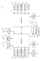
図2は、電子機器1のハードウェア構成を示すブロック図である。
図2に示すように、電子機器1は、第1のCPU(Central Processing Unit)11と、第1のROM(Read Only Memory)12と、第1のRAM(Random Access Memory)13と、第1の記憶部14と、第1のRTC(Real Time Clock)部15と、ドライブ16と、第1の入力部17と、第1の表示部18と、タッチパネル19と、第2のCPU21と、第2のROM22と、第2のRAM23と、第2の記憶部24と、第2のRTC部25と、センサ部26と、第2の入力部27と、第2の表示部28と、ブルートゥース(登録商標)アンテナ31と、ブルートゥースモジュール32と、無線LAN(Local Area Network)アンテナ33と、無線LANモジュール34と、GPSアンテナ35と、GPS(Global Positioning System)モジュール36と、を備えている。
[Hardware configuration]
FIG. 2 is a block diagram illustrating a hardware configuration of the
As shown in FIG. 2, the
電子機器1は、第1のCPU11と、第2のCPU21の制御によって機能する。
具体的に、第1のCPU11は、オペレーティングシステム(OS:Operating System)と、OSの管理下で実行される各種プログラムとに基づいて各種演算処理を行い、演算処理の結果に基づいた各種の処理を実行することにより、電子機器1におけるスマートフォンに類する機能を実現する。例えば、第1のCPU11は、ブルートゥースモジュール32あるいは無線LANモジュール34を介して受信した電子メールの着信や気象情報に関するメッセージ等を第1の表示部18に表示させたりする。また、第1のCPU11は、上述した時刻情報表示処理を実現するための各種処理を実行する。
The
Specifically, the
また、第1のCPU11は、第1の入力部17を介して入力される音声を認識したり、その他、スマートフォンに類する機能として実装された各種機能に係る処理を行ったりする。また、第1のCPU11は、第1のRTC部15から入力された時刻信号を基準として、時刻を計算したり、時刻、曜日あるいは日付等を第1の表示部18に表示させたりする。この場合に、第1のCPU11は、時刻の計算において、GPSモジュール36から取得したGPSの測位情報に含まれる時刻情報に基づいた時刻の補正を行うようにしてもよい。なお、第1のCPU11は、例えば、Android(登録商標)等の汎用のOSに基づいて上述した各種の処理を実現する。
In addition, the
また、本実施形態では、主機能作動状態と、主機能停止状態とを設け、これらの状態を切り替えることを可能とする。第1のCPU11は、主機能作動状態において上述した各種処理を実行する。一方で、第1のCPU11の、主機能停止状態において、動作を停止し、上述した各種処理の実行を行わない。これにより、主機能作動状態では、第1のCPU11による処理を実行することができる。一方で、主機能停止状態では、第1のCPU11や、第1のCPU11に接続された各種のハードウェア(例えば、第1の表示部18や、無線LANモジュール34等の通信モジュール)を停止状態(あるいは一部の機能のみを残して、他の大部分の機能を停止した、いわゆるスリープ状態)とすることにより、電子機器1全体の消費電力を低減させることができる。
Further, in the present embodiment, a main function operation state and a main function stop state are provided, and these states can be switched. The
主機能作動状態と、主機能停止状態との切り替えは、例えば、ユーザの切り替え指示操作に基づいて行われる。他にも、例えば、ユーザからの操作を一定時間受け付けなかったような場合に、主機能作動状態から、主機能停止状態へと切り替えるようにしてもよい。 Switching between the main function operation state and the main function stop state is performed based on, for example, a user's switching instruction operation. Alternatively, for example, when an operation from the user is not received for a certain period of time, the main function operation state may be switched to the main function stop state.
第2のCPU21は、主機能作動状態及び主機能停止状態において、組み込みプログラム等の、特定のプログラムに基づいて各種演算処理を行い、演算処理の結果に基づいた処理を実行することにより、第2の表示部28に対する表示の指示を行ったり、各種センサの検出結果を取得したり、その他、腕時計の機能として実装された各種機能に係る処理を行ったりする。また、第2のCPU21は、上述した時刻情報表示処理を実現するための各種処理を実行する。
In the main function operating state and the main function stopped state, the
また、第2のCPU21は、第2のRTC部25から入力された時刻信号を基準として、時刻を計算したり、時刻、曜日あるいは日付等を第2の表示部28に表示させたりする。また、第2のCPU21は、この計算した時刻、曜日あるいは日付等を第1のCPU11に通知したりする。この場合に、第2のCPU21は、時刻の計算において、第1のCPU11を介してGPSモジュール36から取得したGPSの測位情報に含まれる時刻情報に基づいた時刻の補正を行うようにしてもよい。
In addition, the
第2のCPU21が実行する特定のプログラムの処理(例えば、上記時刻の計算等)は、第1のCPU11が実行するOSの処理に比べて単純な動作であることから処理負荷が小さく、低消費電力で実行可能である。そのため、第2のCPU21に要求されるハードウェアのスペックは、第1のCPU11に比べて低いもので足りる。
そのため、例えば、腕時計としての機能のみが要求される際は、主機能作動状態とすることにより、上述したように、電子機器1全体の消費電力を低減させることができる。この電力の低減に伴い、電子機器1を電子機器1内に内蔵するバッテリ(図示を省略する。)にて長時間稼働させられるため、結果として、電子機器1の稼働時間を拡張することができる。
The processing of a specific program executed by the second CPU 21 (for example, the calculation of the above time) is a simple operation as compared with the processing of the OS executed by the
Therefore, for example, when only the function as a wristwatch is required, the power consumption of the entire
第1のROM12は、第1のCPU11からデータの読み出しが可能であり、第1のCPU11が実行する種々のプログラムや初期設定データを格納する。例えば、第1のROM12は、第1のCPU11が実行するOSのプログラムやOSの管理下で実行される各種プログラムと、時刻情報表示処理を行うための機能を実現するためのプログラムとを格納する。
The
第1のRAM13は、第1のCPU11からデータの読み出し及び書き込みが可能であり、第1のCPU11に作業用のメモリ空間を提供し、作業用の一時データを記憶する。例えば、第1のRAM13は、第1のCPU11がOS等を実行する際のシステム領域やワークエリアを提供したりする。
The
第1の記憶部14は、第1のCPU11からデータの読み出し及び書き込みが可能な不揮発性のメモリであり、例えば、フラッシュメモリやEEPROM(Electrically Erasable and Programmable Read Only Memory)である。第1の記憶部14には、第1のCPU11にて制御にて実現されるスマートフォンに類する各種機能において生成された各種データ(各種設定内容のデータ等)が記憶される。
The
第1のRTC部15は、時刻を計測し、計測した時刻を示す時刻信号を第1のCPU11に対して出力する。
The
ドライブ16には、磁気ディスク、光ディスク、光磁気ディスク、あるいは半導体メモリ等よりなる、リムーバブルメディア81が適宜装着される。リムーバブルメディア81は、第1のCPU11からデータの読み出し及び書き込みが可能であり、各種センサによって検出されたデータ等の各種データを記憶することができる。
A
第1の入力部17は、各種ボタンで構成され、ユーザの指示操作に応じて各種情報を入力する。また、第1の入力部17は、音声を電気信号に変換するマイクを更に備え、入力された音声(操作のための音声コマンド等)を示す信号を第1のCPU11に出力する。
第1の表示部18は、有機ELディスプレイ(OLED:Organic Electro−Luminescence)によって構成され、第1のCPU11の制御に従って、各種情報を表示画面に表示する。
The
The
タッチパネル19は、第2の表示部28の表示画面上に設けられた静電容量方式又は抵抗膜式等のタッチパネルである。タッチパネル19は、操作面に対するユーザのタッチ操作位置と操作内容とを検出して当該操作に応じた信号を発生させて、入力信号として第1のCPU11に出力する。
The
ブルートゥースアンテナ31は、ブルートゥースの規格に基づく電磁波を送受信するアンテナであり、例えばモノポールアンテナ等によって構成される。ブルートゥースアンテナ31は、ブルートゥースモジュール32から入力された無線通信の電気信号を電磁波として送信したり、受信した電磁波を電気信号に変換してブルートゥースモジュール32に出力したりする。
ブルートゥースモジュール32は、第1のCPU11の指示に従って、ブルートゥースアンテナ31を介して他の装置に信号を送信する。また、ブルートゥースモジュール32は、他の装置から送信された信号を受信し、受信した信号が示す情報を第1のCPU11に出力する。
The
The
無線LANアンテナ33は、無線LANモジュール34によって利用される無線通信に対応した周波数の電波を受信可能なアンテナであり、例えばループアンテナやロッドアンテナによって構成される。無線LANアンテナ33は、無線LANモジュール34から入力された無線通信の電気信号を電磁波として送信したり、受信した電磁波を電気信号に変換して無線LANモジュール34に出力したりする。
無線LANモジュール34は、第1のCPU11の指示に従って、無線LANアンテナ33を介して他の装置に信号を送信する。また、無線LANモジュール34は、他の装置から送信された信号を受信し、受信した信号が示す情報を第1のCPU11に出力する。
The
The
GPSアンテナ35は、GPSにおける衛星から発信される電波を受信して電気信号に変換し、変換した電気信号をGPSモジュール36に出力する。
GPSモジュール36は、GPSアンテナ35から入力された電気信号に基づいて、GPSによって示される電子機器1の現在位置(例えば、緯度、経度、及び高度により特定される現在位置)及びGPSによって示される現在時刻を検出する。以下では、このGPSによって示される、電子機器1の現在位置と現在時刻とを含んだ情報を「GPSの測位情報」と称する。また、GPSモジュール36は、検出したGPSの測位情報を第1のCPU11に出力する。
The
The
第2のROM22は、第2のCPU21からデータの読み出しが可能であり、第2のCPU21が実行する特定のプログラムや初期設定データを格納する。例えば、第2のROM22は、腕時計の機能を実現する組み込み用プログラムと、時刻情報表示処理を行うための機能を実現するためのプログラムとを格納する。
The
第2のRAM23は、第2のCPU21からデータの読み出し及び書き込みが可能であり、第2のCPU21に作業用のメモリ空間を提供し、作業用の一時データを記憶する。例えば、第2のRAM23は、第2のCPU21が組み込みプログラム等を実行する際の記憶領域を提供したりする。
The
第2の記憶部24は、第2のCPU21からデータの読み出し及び書き込みが可能な不揮発性のメモリであり、例えば、フラッシュメモリやEEPROMである。第2の記憶部24には、腕時計の機能等において生成された各種データ(各種設定内容のデータ等)が記憶される。
The
第2のRTC部25は、時刻を計測し、計測した時刻を示す時刻信号を第2のCPU21に対して出力する。
The
センサ部26は、種々の情報を測定する複数のセンサの集合である。センサ部26は、例えば、脈拍センサ、地磁気センサ、加速度センサ、ジャイロセンサ、及び照度センサを含む。
脈拍センサは、電子機器1の裏面側(ユーザの腕に面する側)に設置され、電子機器1が装着されたユーザの脈拍を検出し、検出した脈拍を示す情報を第2のCPU21に出力する。
地磁気センサは、地磁気の方向を検出し、検出した地磁気の方向を示す情報を第2のCPU21に出力する。
The
The pulse sensor is installed on the back side of the electronic device 1 (the side facing the user's arm), detects the pulse of the user wearing the
The geomagnetic sensor detects the direction of the geomagnetism, and outputs information indicating the detected direction of the geomagnetism to the
加速度センサは、電子機器1における3軸方向の加速度を検出し、検出した加速度を示す情報を第2のCPU21に出力する。
ジャイロセンサは、電子機器1における3軸方向の角速度を検出し、検出した角速度を示す情報を第2のCPU21に出力する。
照度センサは、例えば、第1の表示部18の裏面側の所定箇所や、電子機器1のベゼル部分の所定箇所等に設置され、電子機器1の表示領域における明るさ(照度)を検出し、検出した明るさを示す情報を第2のCPU21に出力する。
The acceleration sensor detects acceleration in the three axial directions of the
The gyro sensor detects angular velocities of the
The illuminance sensor is installed at, for example, a predetermined location on the back side of the
第2のCPU21は、これら各種センサによって検出された情報を、必要に応じて第1のCPU11に対して出力する。第1のCPU11は、これら各種センサによって検出された情報を、例えばスマートフォンに類する機能により利用する。例えば、第1のCPU11は、照度センサが検出した明るさに基づいて、第1の表示部18の表示画面の輝度を調整する。
The
第2の入力部27は、各種ボタンで構成され、ユーザの指示操作に応じて各種情報を入力する。
The
第2の表示部28は、部分的に又は全体的に光を透過可能なPN(Polymer Network)液晶ディスプレイから構成され、第2のCPU21の制御に従って、各種情報を表示画面に表示(ここではセグメント表示)する。
The
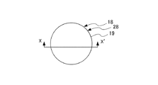
第2の表示部28と第1の表示部18の位置関係について、図3A及び図3Bを参照して説明をする。
図3Aは、電子機器1の表示領域における照度センサ29の設置形態を示す模式図である。また、図3Bは、図3AにおけるX−X’断面を示す模式図である。
The positional relationship between the
FIG. 3A is a schematic diagram illustrating an installation form of the illuminance sensor 29 in a display area of the
図3Aに示すように、第1の表示部18の表示領域と、第2の表示部28の表示領域は、重畳して配置される。
また、図3Bに示すように、電子機器1の表示領域は、表面側からカバーガラスCG、タッチパネル19、第2の表示部28、第1の表示部18、黒色シートBS、メイン基板MBの順に積層された断面構造を有している。これらのうち、黒色シートBSは、第2の表示部28及び第1の表示部18を透過して視認した場合の発色を調整する部材であり、本実施形態では、黒色が視認される構成となっている。また、メイン基板MBには、図2を参照して説明した各ハードウェアが配置されると共に、各ハードウェア間を接続する信号線が配設される。
As shown in FIG. 3A, the display area of the
Further, as shown in FIG. 3B, the display area of the
本実施形態において、第2の表示部28であるPN液晶ディスプレイは、図3Bに示すように、上述した第1の表示部18である有機ELディスプレイの表示画面上に積層されている。このPN液晶ディスプレイは、電位が掛けられていない部位では液晶分子が不規則に並び、光を反射するようになっている。つまり、この電位が掛けられていない部位において、PN液晶ディスプレイによる表示がなされることとなる。
In the present embodiment, the PN liquid crystal display as the
一方、電位が掛けられた部位では、液晶分子が表示画面に対して垂直に整列するので、光を透過可能となっている。つまり、この電位が掛けられた部位では、上述の有機ELディスプレイからの光を透過可能となるので、当該PN液晶ディスプレイを介して当該有機ELディスプレイによる表示を視認することができる。すなわち、電子機器1の表示領域では、第1の表示部18による表示に第2の表示部28による表示を重ね合わせた状態で表示することができるようになっている。
On the other hand, at the portion where the potential is applied, the liquid crystal molecules are aligned vertically to the display screen, so that light can be transmitted. That is, since the light from the above-described organic EL display can be transmitted at the portion where the potential is applied, the display by the organic EL display can be visually recognized through the PN liquid crystal display. That is, in the display area of the
なお、図3Bに示すように、第1の表示部18及び第2の表示部28の表示方向は、各表示部からカバーガラスCGに向かう方向である。これは、図3Aにおける紙面の裏から表に向かう方向に相当する。
In addition, as shown in FIG. 3B, the display direction of the
[機能的構成]
次に、電子機器1の機能的構成について説明する。
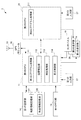
図4は、図1の電子機器1の機能的構成のうち、時刻情報表示処理を実行するための機能的構成を示す機能ブロック図である。
時刻情報表示処理とは、上述したように、時刻の情報と、位置情報とを地図上で対応付けて表示する一連の処理である。
[Functional configuration]
Next, a functional configuration of the
FIG. 4 is a functional block diagram showing a functional configuration for executing the time information display process among the functional configurations of the
As described above, the time information display process is a series of processes for displaying time information and position information in association with each other on a map.
時刻情報表示処理が実行される場合、図4に示すように、第1のCPU11において、第1のプログラム処理部111と、位置特定部112と、時刻取得部113と、表示制御部114と、が機能する。また、時刻情報表示処理が実行される場合、図4に示すように、第2のCPU21において、第2のプログラム処理部211が機能する。
また、第1の記憶部14の一領域には、地図情報記憶部141と、時差情報記憶部142と、が設定される。
以下で特に言及しない場合も含め、これら機能ブロック間では、時刻情報表示処理を実現するために必要なデータを、適切なタイミングで適宜送受信する。
When the time information display process is executed, as shown in FIG. 4, in the
In one area of the
The data necessary for realizing the time information display process is appropriately transmitted and received between these functional blocks at an appropriate timing, even if not particularly mentioned below.
地図情報記憶部141は、地図情報を記憶する。表示制御部114が記憶する地図情報には、例えば、世界地図を表示するための画像情報と、世界地図に対応する緯度及び経度の情報と、世界各国の国境や都市の情報が含まれる。なお、詳細は後述するが、本実施形態では、地図を三次元的な地球儀として回転可能に表示するので、世界地図を表示するための画像情報には、三次元的な表示を行うためのポリゴンデータやテクスチャデータが含まれる。
The map
時差情報記憶部142は、時差情報を記憶する。時差情報記憶部142が記憶する時差情報は、世界各国間の時差や、国内で更に時差がある国に関しては、その国内の領域毎の時差が含まれる。時差は、例えば、それぞれの国等における相対的な時差として管理されてもよいし、グリニッジ標準時を基準とした時差として管理されてもよい。
The time difference
第1のプログラム処理部111は、第1のプログラムに基づいた各種演算処理を行い、演算処理の結果に基づいて各種ハードウェアを制御することにより、スマートフォンに類する機能を実現する。第1のプログラムは、上述した汎用のOSや、スマートフォンに類する機能を実現するためのアプリケーションソフトウェアである。
The first
位置特定部112は、現在位置と、他の位置それぞれを特定する。
位置特定部112は、例えば、GPSモジュール36から出力されるGPSの測位情報に含まれる緯度及び経度の情報と、地図情報記憶部141が記憶する地図情報とに基づいて現在位置を特定する。例えば、位置特定部112は、現在位置の緯度及び経度を特定し、現在位置が、何れの国の何れの都市に属する位置であるかを特定する。他にも、例えば、GPSによる測位が適切に実行できない場合等に、第1の入力部17やタッチパネル19を介したユーザからの操作により、現在位置が特定されてもよい。
The
The
また、位置特定部112は、第1の入力部17やタッチパネル19を介したユーザからの操作に基づいて、他の位置を特定する。例えば、位置特定部112は、ユーザ操作により選択された都市名と、地図情報記憶部141が記憶する地図情報とに基づいて他の位置を特定する。
位置特定部112は、特定した現在位置と、他の位置を、後述の時刻取得部113や表示制御部114に対して出力する。
Further, the
The
時刻取得部113は、位置特定部112が特定した現在位置の時刻と、位置特定部112が特定した他の位置の時刻それぞれを取得する。
時刻取得部113は、例えば、第1のRTC15が出力する時刻信号や、GPSモジュール36から出力されるGPSの測位情報に含まれる時刻情報に基づいて、現在位置の時刻を取得する。
The
The
また、時刻取得部113は、例えば、時差情報記憶部142が記憶する時差情報に基づいて、位置特定部112が特定した現在位置と、位置特定部112が特定した他の位置の時差を特定する。そして、時刻取得部113は、取得している現在位置の時刻と、特定した時差とに基づいた算出により、他の位置の時刻を取得する。
時刻取得部113は、取得した現在位置の時刻と、他の位置の時刻を、後述の表示制御部114に対して、取得の都度、逐次出力する。
Further, the
The
表示制御部114は、位置特定部112が特定した現在位置と他の位置と、時刻取得部113が取得した現在位置の時刻と他の位置の時刻とに基づいて、各情報の表示位置を決定する。また、表示制御部114は、決定した各情報の表示位置に基づいて、表示用の画像を生成し、生成した画像を第1の表示部18に表示させる。
例えば、表示制御部114は、時刻取得部113が取得した現在位置の時刻を、現在位置の地図上の位置と対応付けて地図上に配置すると共に、時刻取得部113が取得した他の位置の時刻を、他の位置の地図上の位置と対応付けて現在位置の時刻を配置した地図と同一の地図上に配置する。そして、表示制御部114は、このようにして現在位置の時刻及び他の位置の時刻を配置した地図を表示部18に表示する。
表示制御部114による各情報の表示位置の決定方法や、これにより生成された画像の表示例については、後述の[表示位置の決定と表示例]の欄で詳細に説明する。
なお、このような世界各地の時刻を表示する機能(又はこのような世界各地の時刻そのもの)は「ワールドタイム」等の名称で呼ばれることがある。
The
For example, the
A method of determining the display position of each information by the
Note that such a function of displaying times around the world (or such times around the world itself) may be referred to by a name such as “world time”.
第2のプログラム処理部211は、第1のプログラムとは異なるプログラムに基づいた各種演算処理を行い、演算処理の結果に基づいて各種ハードウェアを制御することにより、腕時計の機能等を実現する。第2のプログラムは、上述した組み込みプログラムである。第2のプログラム処理部211は、電子機器1の電源投入に伴い起動し、動作状態に関わらず動作を継続する。一方で、上述したように、主機能作動状態にある場合に、第1のCPU11は動作し、上述した各機能ブロックを機能させる。また、主機能停止状態にある場合に、第1のCPU11は動作を停止し、上述した各機能ブロックを機能させることにより、電子機器1全体の消費電力を低減させることができる。
The second
[表示位置の決定と表示例]
次に、図5及び図6を参照して、表示制御部114による、表示位置の決定方法と、これにより生成された画像の表示例について説明する。ここで、図5及び図6は、以下で説明する表示位置の決定方法に基づいて表示される表示例を示す図である。
なお、以下説明する内容は、一例に過ぎず、表示制御部114による、表示位置の決定方法や、表示態様については、以下説明する例に特に限定されない。
[Determination of display position and display example]
Next, a method of determining a display position by the
Note that the content described below is merely an example, and the method of determining the display position and the display mode by the
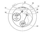
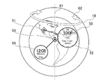
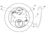
図5には、第1の表示部18と、この第1の表示部18におけるユーザが視認可能な表示領域である表示領域50を図示する。表示領域50には、地図として少なくとも半球分(すなわち、経度180度分)の表示領域が含まれる地球儀が表示される。地球儀の表示方向は任意でよいが、ここでは一例として、表示領域50を参照するユーザにとって、赤道に正対した方向で地球儀が表示される。すなわち、地球の自転軸がユーザの視線に対し垂直になる方向で地球儀が表示される。この地球儀の画像は、表示制御部114が、地図情報記憶部141に記憶されている地図情報に基づいて生成する。
FIG. 5 illustrates the
また、地図上には、地図上の現在位置51と現在位置の時刻52が対応付けて表示される。対応付けは、例えば、図示するように地図上の現在位置51と現在位置の時刻52を結ぶ線(以下、「結合線」と称する。)により、他の位置に関する情報等とは識別可能に表示される。同様に、地図上には、地図上の他の位置53と他の位置の時刻54が対応付けて表示される。対応付けは、例えば、現在位置と同様に、結合線により表示される。なお、図中では、結合線として、直線を想定しているが、結合線は、その一部又は全部が曲線であってもよく、あるいは破線等であってもよい。
Further, the
図中では、地図上の現在位置51としてサンフランシスコが表示され、地図上の他の位置53としてメキシコシティが表示されている。また、これら双方を表示可能な縮尺で、これら双方を含んだ領域の地図が表示されている。ここで、現在位置と他の位置が比較的近い場合には地図を拡大表示したり、現在位置と他の位置が比較的遠い場合には地図を縮小表示したりすることにより、視認性を向上させることができる。
In the figure, San Francisco is displayed as the
また、地図上の現在位置51と地図上の他の位置53の何れが現在位置で、何れが他の位置であるかをユーザに認識させるように表示を行うとよい。例えば、現在位置の時刻52を装飾のある比較的大きなダイヤルの時計として表示し、地図上の現在位置51と対応付けることにより、地図上の現在位置51が現在位置であることをユーザに認識させることができる。一方で、他の位置の時刻54を簡素な比較的小さなダイヤルの時計として表示し、地図上の他の位置53と対応付けることにより、地図上の他の位置53が他の位置であることをユーザに認識させることができる。
Further, the display may be performed so that the user can recognize which of the
更に、図中には、地図回転軸61と、矢印62を図示する。地図回転軸61は、地球儀として表示されている地図が回転する際の回転軸である。ここでは一例として、地図回転軸61は、地球の自転軸と同じ軸方向に設定される。また、矢印62は、地球儀として表示されている地図が回転することを示す概念的な矢印である。これら地図回転軸61及び矢印62は、実際に表示領域50に表示される情報ではなく、説明の便宜のために図示している情報である。
Further, in the drawing, a
表示制御部114による、これら各情報の表示位置の決定方法の一例について説明する。表示制御部114は、基本的な配置として、地図上の現在位置の表示位置を、現在位置に対応する子午線が、表示領域50の正中となる位置(本例では、地図回転軸61と重なる位置に相当)に決定する。このように地図上の現在位置の表示位置を決定すると、表示制御部114は、現在位置の緯度及び経度と、他の位置の緯度及び経度の相対関係に基づいて、地図上の現在位置の表示位置を決定する。
図5の例では、これらの決定に基づいて、地図上の現在位置51が表示領域50の正中となる位置に表示される。また、メキシコシティは、サンフランシスコよりも東側に位置するので、地図上の他の位置53が現在位置の時刻52の右側に表示される。
An example of a method of determining the display positions of these pieces of information by the
In the example of FIG. 5, based on these determinations, the
次に、表示制御部114は、この決定に基づいて地図上の現在位置を正中に表示した場合に、他の位置が正中より東の場合は、地図上の現在位置の時刻の位置の表示位置を正中よりも左側に決定する。一方で、表示制御部114は、他の位置が正中より西の場合は、地図上の現在位置の時刻の位置の表示位置を正中よりも右側に決定する。これにより、比較的大きなダイヤルで表示される現在位置の時刻と、地図上の他の位置とが、相互に干渉しない位置(例えば、各表示が重畳しない位置)に表示される。
Next, based on this determination, the
そして、これらの決定に基づいて、地図上の現在位置、地図上の他の位置、及び現在位置の時刻の表示位置が決定した後に、表示制御部114は、これらと干渉しない位置に、他の位置の時刻の表示位置を決定する。
図5の例では、これらの決定に基づいて、現在位置の時刻52が正中よりも左側に表示される。また、他の位置の時刻54が、他の情報と干渉しない位置に表示される。
Then, based on these determinations, after the current position on the map, another position on the map, and the display position of the time of the current position are determined, the
In the example of FIG. 5, the
すなわち、表示制御部114は、現在位置と他の位置の、緯度及び経度の相対関係に基づいて、各情報が干渉しないように、各情報の表示位置を決定することができる。また、表示制御部114は、各情報が干渉しない範囲において、各時刻表示の大きさや表示位置を決定することができる。
また、表示制御部114は、同様にして、他の位置が正中に表示されるようにして、各情報の表示位置を決定してもよい。この場合、上述した表示位置の決定方法の説明における現在位置を他の位置と読み替え、他の位置を現在位置と読み替えて、同様の方法により表示位置を決定することができる。すると、図6に示すように各情報の表示位置が決定される。
That is, the
Similarly, the
表示制御部114は、ユーザの操作に応じて、地図上の現在位置が正中となる表示(すなわち、図5に示すような表示)と、地図上の他の位置が正中となる表示(すなわち、図6に示すような表示)と、を切り替えて表示してもよい。例えば、現在位置の時刻を示すダイヤルをユーザがタップ操作等した場合に、地図上の現在位置が正中となる表示とし、他の位置の時刻を示すダイヤルをユーザがタップ操作等した場合に、地図上の他の位置が正中となる表示とするように切り替えて表示してもよい。また、例えば、まず何れか一方を表示させて、所定時間が経過後に他方に表示を切り替えるようにしてもよい。また、この場合に、更に、地図上の現在位置と、地図上の他の位置との中央が正中となる表示に切り替えるようにしてもよい。
更に、表示位置の切り替えと共に時刻の表示態様も切り替えるようにしてもよい。例えば、正中に他の位置の時刻54を表示する場合には、他の位置の時刻54を装飾のある比較的大きなダイヤルの時計として表示し、その一方で、現在位置の時刻52を簡素な比較的小さなダイヤルの時計として表示するようにしてもよい。
The
Furthermore, the display mode of the time may be switched together with the switching of the display position. For example, when displaying the
また、表示制御部114は、この切り替え時に、各情報を瞬時に切り替えるのではなく、移動の経過をアニメーションにより表示するとよい。すなわち、地図回転軸61を回転軸として矢印62に示すように地球儀として表示している地図を回転させると共に、各情報の移動の経過をアニメーションにより表示するとよい。このようにアニメーション表示をすることにより、ユーザに。現在位置と他の位置の地図上の相対的な位置関係を直感的に把握させることができる。また、現在位置や他の位置を参照しやすいように地図を移動させ、視認性を向上させることができる。更に、アニメーションを鑑賞することができるので、ユーザに、表示に対する興味を抱かせることができる。
Further, at the time of this switching, the
[動作]
図7は、図4の機能的構成を有する図1の電子機器1が実行する時刻情報表示処理の流れを説明するフローチャートである。
時刻情報表示処理は、例えば、電子機器1への電源投入と共に、あるいはユーザによる時刻情報表示処理の実行指示を示す操作と共に開始される。
[motion]
FIG. 7 is a flowchart illustrating the flow of the time information display process executed by the
The time information display process is started, for example, when the power to the
ステップS11において、位置特定部112は、現在位置を特定する。位置特定部112は、特定した現在位置を、時刻取得部113や表示制御部114に対して出力する。
ステップS12において、位置特定部112は、他の位置を特定する。位置特定部112は、特定した他の位置を、時刻取得部113や表示制御部114に対して出力する。
In step S11, the
In step S12, the
ステップS13において、時刻取得部113は、ステップS11において特定された現在位置の時刻の取得を開始する。時刻取得部113は、以後現在位置の時刻の取得を継続し、取得した現在位置の時刻を表示制御部114に対して、取得の都度、逐次出力する。
ステップS14において、時刻取得部113は、ステップS12において特定された他の位置の時刻の取得を開始する。時刻取得部113は、以後現在位置の時刻の取得を継続し、取得した他の位置の時刻を表示制御部114に対して、取得の都度、逐次出力する。
In step S13, the
In step S14, the
ステップS15において、表示制御部114は、[表示位置の決定と表示例]の欄で上述したような方法で、各情報の表示位置を決定する。
In step S15, the
ステップS16において、表示制御部114は、ステップS15において決定した表示位置に基づいて、表示用の画像を生成し、第1の表示部18に生成した画像の表示を開始させる。
In step S16, the
ステップS17において、表示制御部114は、表示を変更するか否かを判定する。例えば、表示制御部114は、[表示位置の決定と表示例]の欄で上述したように、他の位置を正中位置に表示をし、所定時間が経過した場合に、表示を変更する。あるいは、表示制御部114は、ユーザから、地図上の現在位置や他の位置のタップ操作等があった場合に、表示を変更する。
表示を変更する場合は、ステップS17においてYesと判定され、処理はステップS15に戻る。そして、表示制御部114は、表示を変更すると判定した理由(例えば、上述の時間経過やユーザからの操作)に応じて、新たに表示位置を決定し、ステップS16以後の処理を繰り返す。一方で、表示を変更しない場合は、ステップS17においてNoと判定され、処理はステップS18に進む。
In step S17, the
If the display is to be changed, Yes is determined in step S17, and the process returns to step S15. Then, the
ステップS18において、表示制御部114は、時刻情報表示処理を終了する条件を満たしたか否かを判定する。時刻情報表示処理を終了する条件は、例えば、ユーザから終了指示を示す操作を受け付けたことや、ユーザから他のアプリケーションソフトウェアの起動指示を示す操作を受け付けたことや、ユーザの移動に伴い現在位置が変更となったことや、ユーザから他の位置の再選択指示を示す操作を受け付けたことである。
In step S18, the
時刻情報表示処理を終了する条件が満たされない場合は、ステップS18においてNoと判定され、処理はステップS17に戻る。そして、再度ステップS17の判定が行われる。一方で、時刻情報表示処理を終了する条件が満たされた場合は、ステップS18においてYesと判定され、時刻情報表示処理は終了する。 If the condition for terminating the time information display process is not satisfied, No is determined in step S18, and the process returns to step S17. Then, the determination in step S17 is performed again. On the other hand, if the condition for ending the time information display process is satisfied, it is determined as Yes in step S18, and the time information display process ends.
以上説明したようにして、時刻情報表示処理は実現される。そして、この時刻情報表示処理により、例えば、図5や図6を参照して上述した表示例のような表示が行われる。
この表示を参照したユーザは、各位置について、地図上の位置と時刻、及びそれらの対応関係を直感的に把握することができる。
すなわち、本実施形態である電子機器1によれば、複数の時刻に関する情報を、より分かりやすく提供することが可能となる。
As described above, the time information display process is realized. Then, by the time information display process, for example, a display like the display example described above with reference to FIGS. 5 and 6 is performed.
The user who refers to this display can intuitively grasp, for each position, the position on the map, the time, and the correspondence between them.
That is, according to the
[変形例]
次に、上述した実施形態を変形した、いくつかの変形例について説明する。ただし、以下に説明する変形例は、あくまで例示に過ぎず、本実施形態を適用可能な変形例を限定するものではない。また、以下に説明する変形例同士を組み合わせることも可能である。
[Modification]
Next, some modified examples obtained by modifying the above-described embodiment will be described. However, the modified examples described below are merely examples, and do not limit the modified examples to which the present embodiment can be applied. Further, it is also possible to combine the modifications described below.
[変形例1]
上述した実施形態では、[表示位置の決定と表示例]の欄で説明した方法にて、各情報の表示位置を決定していた。これに限らず、他の方法で、各情報の表示位置を決定してもよい。
[Modification 1]
In the above-described embodiment, the display position of each piece of information is determined by the method described in the section of “Determination of Display Position and Display Example”. The present invention is not limited to this, and the display position of each information may be determined by another method.
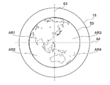
他の決定方法の一例について図8及び図9を参照して説明する。ここで、図8は、本変形例における領域の区分けについて説明する図である。また、図9は、領域の区分けに基づいて各情報の表示位置を決定するためのテーブルを示す図である。
本決定方法において、表示制御部114は、まず、地球儀として表示する地図を複数の領域に区分けする。ここでは、図8に示すように、区分線63及び区分線64により、地図を第1領域AR1、第2領域AR2、第3領域AR3及び第4領域AR4の4つの領域に区分けする。なお、これら区分線63及び区分線64は、実際に表示領域50に表示される情報ではなく、説明の便宜のために図示している情報である。
そして、表示制御部114は、地図上の現在位置の表示位置を、ランダムにあるいは予め定めた所定の法則に基づいて、何れかの領域に決定する。また、表示制御部114は、現在位置の緯度及び経度と、他の位置の緯度及び経度の相対関係に基づいて、地図上の他の位置の表示位置を決定する。
An example of another determination method will be described with reference to FIGS. Here, FIG. 8 is a diagram illustrating the division of the area in the present modification. FIG. 9 is a diagram showing a table for determining the display position of each information based on the division of the area.
In the present determination method, the
Then, the
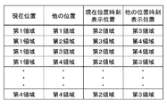
このようにして、地図上の現在位置の表示位置と、地図上の他の位置の表示位置が決定した場合、次に、表示制御部114は、図9に示すテーブルを参照する。このテーブルには、現在位置と他の位置それぞれの表示位置の組み合わせと、対応する時刻の表示位置であって、それぞれが干渉しないように設定された時刻の表示位置が格納されている。
表示制御部114は、このテーブルを参照して、今回決定した現在位置と他の位置それぞれの表示位置の組み合わせに対応する表示位置を特定する。例えば、表示制御部114は、地図上の現在位置の表示位置が第1領域AR1であって、地図上の他の位置の表示位置が第2領域AR2である場合には、テーブルの二行目を参照し、そこで特定されているように、現在位置の時刻の表示位置を第3領域AR3と決定し、他の位置の時刻の表示位置を第4領域AR4と決定する。
When the display position of the current position on the map and the display position of another position on the map are determined in this way, next, the
The
このようにして、表示制御部114は、テーブルを利用して各情報が干渉しないように、各情報の表示位置を決定することができる。このようなテーブルを、例えば、複数用意しておき、何れかのテーブルを、ランダムにあるいは予め定めた所定の法則に基づいて、選択してもよい。これにより、各情報が干渉しないとうい条件を満たしつつ、バリエーションに富んだ表示を行うことが可能となる。
In this way, the
上述した例は、地図上の現在位置の表示位置と、地図上の他の位置の表示位置に基づいて、時刻の表示位置を決定する方法である。他の方法として、現在位置の時刻の表示位置と、他の位置の時刻の表示位置とを、互いに対応付けて決定してもよい。
この場合、例えば、表示制御部114は、現在位置の時刻の表示位置と、他の位置の時刻の表示位置との、何れの位置を先に決定するのかについての決定順序を、ランダムにあるいは予め定めた所定の法則に基づいて、決定する。そして、表示制御部114は、決定順序が先に決定された時刻の表示位置を、ランダムにあるいは予め定めた所定の法則に基づいて、決定する。また、表示制御部114は、決定順序が次に決定された時刻の表示位置は、先に決定された時刻の表示位置以外の場所から、ランダムにあるいは予め定めた所定の法則に基づいて、決定する。例えば、先に決定された時刻の表示位置が地図の左側と決定された場合に、決定順序が次に決定された時刻の表示位置は右側と決定する。このようにして、現在位置の時刻の表示位置と、他の位置の時刻の表示位置とを、互いに対応付けて決定してもよい。
The example described above is a method of determining the display position of the time based on the display position of the current position on the map and the display positions of other positions on the map. As another method, the display position of the time at the current position and the display position of the time at another position may be determined in association with each other.
In this case, for example, the
また、他にも例えば、ユーザの意図を反映して各時刻の表示位置を決定してもよい。例えば、表示制御部114は、ユーザによる選択操作に基づいて、各時刻の表示位置を決定してもよい。選択操作は、例えば、表示可能な位置を選択肢としてユーザに提示し、ユーザがこの選択肢から選択する方法であってもよい。あるいは、ユーザが時刻表示に対応するダイヤルをスワイプ操作等で移動させることにより、表示位置を選択してもよい。この場合にも、移動の経過をアニメーションにより表示するとよい。また、移動の経過において、移動対象としている時刻表示が、他の時刻表示と干渉する場合には、他の時刻表示の表示位置を変更したり、他の時刻表示の大きさを小さくしたりすることにより、干渉が発生しないようにしてもよい。
Further, for example, the display position at each time may be determined by reflecting the intention of the user. For example, the
[変形例2]
上述の実施形態では、図5及び図6を参照して上述したように、地図回転軸61は、地球の自転軸と同じ軸方向に設定されていた。そして、地図回転軸61を回転軸として地球儀として表示された地図を回転していた。これに限らず他の軸方向を回転軸として地球儀として表示された地図を回転してもよい。
本変形例では、現在位置と他の位置の緯度及び経度の相対関係に基づいて、回転軸を決定する。例えば、現在位置と他の位置が何れも北半球である場合には、回転軸を自転軸と直交する軸方向として、地図を回転させる。
[Modification 2]
In the above embodiment, as described above with reference to FIGS. 5 and 6, the
In this modification, the rotation axis is determined based on the relative relationship between the current position and the latitude and longitude of the other positions. For example, when both the current position and the other positions are in the northern hemisphere, the map is rotated with the rotation axis set as the axis direction orthogonal to the rotation axis.
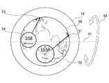
具体的な表示例を図10及び図11を参照して説明する。ここで、図10は、本変形例における表示位置の決定方法について説明するための表示例を示す図である。図11は、本変形例における表示位置の決定方法に基づいて表示される表示例を示す図である。本例では、現在位置が東京であり、他の位置がミュンヘンである場合を想定する。ここで、東京及びミュンヘンは、共に北半球の北極点に近い位置にある。そのため、図5や図6の例のように、ユーザにとって、赤道に正対した方向で地球儀を表示すると、図10に示すような表示となり、地図上の現在位置51及び地図上の他の位置53の周囲の地図が十分に把握できない表示となる。
そこで、表示制御部114は、このように現在位置と他の位置が共に北極点に近い位置にある場合には、図示するように地図回転軸61を自転軸と直交する軸方向として、地図を回転させる。これにより、図11に示すように、北半球が大きくクローズアップされ、図10に示す表示と比較して、地図上の現在位置51及び地図上の他の位置53の周囲の地図が十分に把握できる表示となる。
A specific display example will be described with reference to FIGS. Here, FIG. 10 is a diagram illustrating a display example for describing a method of determining a display position in the present modified example. FIG. 11 is a diagram illustrating a display example displayed based on the display position determining method in the present modification. In this example, it is assumed that the current position is Tokyo and another position is Munich. Here, both Tokyo and Munich are located near the North Pole in the Northern Hemisphere. Therefore, when the user displays the globe in a direction directly facing the equator as in the examples of FIGS. 5 and 6, the display becomes as shown in FIG. 10, and the
Therefore, when the current position and the other position are both located near the North Pole, the
なお、表示制御部114は、現在位置と他の位置が共に南極点に近い位置にある場合にも、同様に地図回転軸61を自転軸と直交する軸方向として、南半球を大きくクローズアップした表示とするとよい。また、表示制御部114は、現在位置と他の位置の緯度及び経度の相対関係に基づいて、自転軸の軸方向や、自転軸と直交する軸方向以外の、他の軸方向を回転軸として回転してもよい。
また、現在位置と他の位置との地図上における座標に基づいて、地図回転軸61を自転軸の軸方向として回転させるのか、地図回転軸61を自転軸と直交する軸方向として回転させるのか、あるいは、地図回転軸61を自転軸の軸方向や自転軸と直交する軸方向以外の他の軸方向として回転させるのか、を選択し、好適な表示形態(例えば、図10のような表示形態ではなく、図5、6又は図11のような表示形態)となるように、選択された回転軸でもって地図を回転させるようにしてもよい。更に、現在位置と他の位置との地図上における座標に基づいて、複数の軸方向に対応した複数の地図回転軸61を選択し、好適な表示形態(例えば、図10のような表示形態ではなく、図5、6又は図11のような表示形態)となるように、これら複数の地図回転軸61それぞれでもって地図を回転させるようにしてもよい。
Note that the
Further, based on the coordinates of the current position and other positions on the map, whether to rotate the
[変形例3]
上述した実施形態では、表示位置の決定方法に基づいて、現在位置及び他の位置と、これら各位置に対応する時刻とを地図上に表示していた。これに限らず、更に他の情報を地図上に表示してもよい。図12は、表示位置の決定方法に基づいて表示される情報に、他の情報を更に表示した場合の一例を示す図である。
この図12に夜間帯表示55として示すように、夜間帯の領域を示す情報を表示してもよい。この場合、夜間帯表示55を、例えば、透過性のある黒色で示してもよい。更に、夜間帯表示55を、日中帯の領域に近づくにつれて色の表示が段階的に変化するようにグラデーション表示としてもよい。更に、夜間衛星写真が取得できる場合には、夜間帯表示55を夜間衛星写真に基づいて生成してもよい。これにより、例えば、夜間における各都市部の光量等を表現することができる。
[Modification 3]
In the above-described embodiment, the current position and other positions and the time corresponding to each of the positions are displayed on the map based on the method of determining the display position. The present invention is not limited to this, and other information may be displayed on a map. FIG. 12 is a diagram illustrating an example of a case where other information is further displayed on the information displayed based on the display position determination method.
As shown in FIG. 12 as a
[変形例4]
上述した実施形態では、現在位置や他の位置と、それぞれの位置に対応する時刻との対応付けを、結合線の表示により行っていた。これに限らず、他の表示により、対応付けを行ってもよい。例えば、現在位置や他の位置と、それぞれの位置に対応する時刻とを、それぞれ重畳表示することにより、対応付けを行ってもよい。また、これ以外にも、例えば、現在位置や他の位置と、それぞれの位置に対応する時刻とを、それぞれ同じ色や、同じ表示態様(例えば、現在位置及び現在位置の時刻と、他の位置及び他の位置の時刻の、一方についてのみ点滅させる。)で表示することにより、対応付けを行ってもよい。
[Modification 4]
In the above-described embodiment, the association between the current position or another position and the time corresponding to each position is performed by displaying the connection line. However, the present invention is not limited to this, and the association may be performed by another display. For example, the current position or another position and the time corresponding to each position may be associated with each other by superimposing them. In addition to this, for example, the current position and other positions and the time corresponding to each position are displayed in the same color and in the same display mode (for example, the current position and the time of the current position and the other positions). And only one of the time at the other position and the time at the other position are blinked.).
[変形例5]
上述した実施形態では、現在位置と、1つの他の位置とを表示の対象として、それぞれの位置に対応する時刻と対応付けて表示していた。これに限らず、他の方法で表示を行うようにしてもよい。例えば、ユーザに2つ以上の都市名を選択させる等の操作を行わせることにより、2つ以上の他の位置を特定し、この特定した2つ以上の他の位置を表示の対象としてもよい。すなわち、現在位置と、2つ以上の他の位置とを表示の対象として、それぞれの位置に対応する時刻と対応付けて表示してもよい。また、この場合に、そもそも現在位置を表示の対象とせずに、2つ以上の他の位置を表示の対象として、それぞれの位置に対応する時刻と対応付けて表示してもよい。
[Modification 5]
In the above-described embodiment, the current position and one other position are displayed and displayed in association with the times corresponding to the respective positions. The display is not limited to this, and may be performed by another method. For example, by causing the user to perform an operation such as selecting two or more city names, two or more other positions may be specified, and the specified two or more other positions may be displayed. . That is, the current position and two or more other positions may be displayed and associated with the time corresponding to each position. Further, in this case, two or more other positions may be displayed in association with the time corresponding to each position without displaying the current position in the first place.
また、このようにして3つ以上の位置を表示の対象とした場合に、各位置の緯度及び経度の関係性によっては、地球儀として表示している地図に同時に2つの位置に関する情報しか表示できない場合がある。例えば、3つの位置の経度がそれぞれ120度前後離れている場合には、半球分(すなわち、経度180度分)の表示領域が含まれる地球儀として表示している地図に同時に2つの位置に関する情報しか表示できない。このような場合は、ユーザの操作や、時間経過等を条件に、地図を回転させることによって、表示対象とする位置を切り替えるようにするとよい。また、この場合にも、各情報を瞬時に切り替えるのではなく、移動の経過をアニメーションにより表示するとよい。 Further, when three or more positions are to be displayed as described above, depending on the relationship between the latitude and longitude of each position, only information on two positions can be simultaneously displayed on the map displayed as a globe. There is. For example, if the longitudes of the three positions are separated by about 120 degrees, information on the two positions is only displayed on a map displayed as a globe including a display area of a hemisphere (that is, 180 degrees of longitude) at the same time. Cannot display. In such a case, the position to be displayed may be switched by rotating the map on the condition of a user operation, the passage of time, or the like. Also in this case, the progress of the movement may be displayed by animation instead of instantaneously switching each piece of information.
[構成例]
以上のように構成される電子機器1は、位置特定部112と、時刻取得部113と、表示制御部114と、を有する。
位置特定部112は、現在位置を特定する。また、位置特定部112は、現在位置とは異なる他の位置を特定する。
時刻取得部113は、現在位置の時刻を取得する。また、時刻取得部113は、他の位置の時刻を取得する。
表示制御部114は、時刻取得部113が取得した現在位置の時刻を、現在位置の地図上の位置と対応付けて第1位置の時刻を配置した地図と同一の地図上に配置すると共に、時刻取得部113が取得した他の位置の時刻を、他の位置の地図上の位置と対応付けて地図上に配置する。また、表示制御部114は、第1位置の時刻及び第2位置の時刻を配置した地図を表示する。
この電子機器1による表示を参照したユーザは、各位置について、地図上の位置と時刻、及びそれらの対応関係を直感的に把握することができる。
すなわち、本実施形態である電子機器1によれば、複数の時刻に関する情報を、より分かりやすく提供することが可能となる。
[Configuration example]
The
The
The
The
The user who has referred to the display by the
That is, according to the
表示制御部114は、現在位置の時刻の地図上の表示位置と、他の位置の時刻の地図上の表示位置とを、互いに対応付けて決定する。
これにより、それぞれの時刻の表示位置を対応付けに基づいて、時刻の適切な表示位置を決定することができる。
The
This makes it possible to determine an appropriate display position of the time based on the association of the display position of each time.
表示制御部114は、現在位置の時刻の地図上の表示位置と、他の位置の時刻の地図上の表示位置とを、現在位置の地図上の位置及び他の位置の地図上の位置に基づいて決定する。
これにより、それぞれの地図上の位置に基づいて、時刻の適切な表示位置を決定することができる。
The
This makes it possible to determine an appropriate time display position based on the position on each map.
表示制御部114は、現在位置の時刻の表示位置及び他の位置の時刻の表示位置を決定した場合に、現在位置の時刻及び他の位置の時刻の、決定した表示位置までの移動の経過を表示する。
これにより、時刻の移動の経過を、例えばアニメーション等でユーザに参照させることができるので、地図上の相対的な位置関係を直感的に把握させることができる。また、ユーザに、時刻表示に対する興味を抱かせることができる。
When the
This allows the user to refer to the progress of the time movement by, for example, animation or the like, so that the relative positional relationship on the map can be intuitively grasped. Further, it is possible to make the user interested in the time display.
表示制御部114は、地図を移動させると共に、地図の移動の経過を表示する。
これにより、現在位置や他の位置を参照しやすいように地図を移動させ、視認性を向上させることができる。また、ユーザに、地図表示に対する興味を抱かせることができる。
The
Thereby, the map can be moved so that the current position and other positions can be easily referred to, and the visibility can be improved. In addition, it is possible to make the user interested in the map display.
表示制御部114は、地図上の現在位置の時刻の表示位置と、地図上の他の位置における時刻の表示位置とが干渉しないように表示を制御する。
これにより、例えば、各時刻表示が一部あるいは全部重畳したりして、参照できなくなることを防止することができる。
The
Thereby, for example, it is possible to prevent the time display from being partially or entirely superimposed and being unable to be referred to.
表示制御部114は、地図上の現在位置の時刻の表示位置と、地図上の他の位置における時刻の表示位置とが干渉しないように、時刻の表示の大きさ及び表示位置の何れか又は双方を制御する。
これにより、時刻の表示の大きさや表示位置を制御することで、各時刻表示が一部あるいは全部重畳したりして、参照できなくなることを防止することができる。
The
Thus, by controlling the size and the display position of the time display, it is possible to prevent the time display from being partially or entirely superimposed and being unable to be referred to.
表示制御部114は、現在位置の時刻と現在位置の地図上の位置との対応関係と、他の位置の時刻と他の位置の地図上の位置との対応関係とを示す表示として、対応関係のある位置と時刻を繋ぐ情報の表示、又は、対応関係のある位置と時刻の重畳表示を行う。
これにより、ユーザに地図上の位置と時刻との対応関係を明示することができる。
The
This allows the user to clearly indicate the correspondence between the position on the map and the time.
表示制御部114は、地図として、少なくとも半球分の表示領域が含まれる地球儀を表示する。
これにより、現在位置と、他の位置の距離が離れていても(例えば、経度が180度離れていても)、現在位置と、他の位置の双方を表示することができる。
The
Thereby, even if the distance between the current position and another position is large (for example, the longitude is 180 degrees apart), both the current position and the other position can be displayed.
表示制御部114は、地図として、現在の時間帯が第1の時間帯である領域と、現在の時間帯が第2の時間帯である領域とを識別可能な地図を表示する。
これにより、ユーザは、地図上の何れの領域が何れの時間帯であるかを直感的に把握することができる。
The
Thereby, the user can intuitively grasp which area on the map corresponds to which time zone.
表示制御部114は、現在位置と他の位置との離間距離に応じて、地図表示の縮尺を変化させると共に、縮尺の変化に連動して、地図上の現在位置の時刻の表示位置と、地図上の他の位置における時刻の表示位置とを変化させる。
これにより、現在位置と他の位置が比較的近い場合には地図を拡大表示したり、現在位置と他の位置が比較的遠い場合には地図を縮小表示したりすることにより、視認性を向上させることができる。
The
This improves visibility by enlarging the map when the current position and other positions are relatively close, and by reducing the map when the current position and other positions are relatively distant. Can be done.
表示制御部114は、ユーザの操作に応じて地図上の現在位置の時刻の表示位置と、地図上の他の位置における時刻の表示位置との何れか一方を変化させる共に、他方の時刻の表示の大きさ及び表示位置の何れか又は双方を変化させる。
これにより、ユーザが所望した位置の時刻表示を大きくする一方で、他の時刻表示を小さくすることができる。すなわち、ユーザの意図を反映することができる。
The
Thereby, while the time display at the position desired by the user is increased, the other time displays can be reduced. That is, the intention of the user can be reflected.
表示制御部114は、地図に配置された現在位置の時刻及びそれに対応する現在位置と、他の位置の時刻及びそれに対応する他の位置とを同時に表示するように地図を表示する。
これにより、ユーザは、地図上における各位置と、各位置それぞれに対応する時刻という時刻に関する複数の情報を同時に視認することができる。そのため、ユーザは、これらの情報を相対的に比較することができる。
The
Thus, the user can simultaneously visually recognize a plurality of pieces of information on each position on the map and time corresponding to each position. Therefore, the user can relatively compare these pieces of information.
表示手段は、地図に配置された現在位置の時刻及びそれに対応する現在位置と、他の位置の時刻及びそれに対応する他の位置とを切り替え表示するように地図を表示する。
これにより、ユーザは、地図上における何れかの位置と、この何れかの位置に対応する時刻を同時に視認することができる。そのため、ユーザは、位置と時刻との対応関係を正確に把握することができる。
The display means displays the map so as to switch and display the time of the current position arranged on the map and the current position corresponding to the current position, and the time of another position and another corresponding position.
Thus, the user can simultaneously visually recognize any position on the map and the time corresponding to any of the positions. Therefore, the user can accurately grasp the correspondence between the position and the time.
[本発明の変形、改良等] [Modifications and improvements of the present invention]
以上、本発明の実施形態及びその変形例について説明したが、この実施形態及びその変形例は、例示に過ぎず、本発明の技術的範囲を限定するものではない。本発明はその他の様々な実施形態及びその変形例を取ることが可能であり、さらに、本発明の要旨を逸脱しない範囲で、変形、改良、省略、及び置換等種々の変更を行うことができる。この実施形態及びその変形例や、その変形は、本明細書等に記載された発明の範囲や要旨に含まれると共に、特許請求の範囲に記載された発明とその均等の範囲に含まれる。 The embodiment of the present invention and the modification thereof have been described above. However, the embodiment and the modification thereof are merely examples, and do not limit the technical scope of the present invention. The present invention can take various other embodiments and modified examples thereof, and can make various changes such as modifications, improvements, omissions, and substitutions without departing from the gist of the present invention. . This embodiment, its modifications, and its modifications are included in the scope and spirit of the invention described in this specification and the like, and are also included in the invention described in the claims and the equivalents thereof.
また、上述の実施形態及びその変形例では、本発明が適用される電子機器1は、腕時計型の装置(スマートウォッチ等)を例として説明したが、特にこれに限定されない。
例えば、本発明は、電子機器一般に適用することができる。具体的には、例えば、本発明は、据え置き型のパーソナルコンピュータ、ノート型のパーソナルコンピュータ、スマートフォン、携帯電話機、ポータブルゲーム機、デジタルカメラ、ビデオカメラ、携帯型ナビゲーション装置等に適用可能である。
Further, in the above-described embodiment and its modified example, the
For example, the present invention can be applied to electronic devices in general. Specifically, for example, the present invention is applicable to a stationary personal computer, a notebook personal computer, a smartphone, a mobile phone, a portable game machine, a digital camera, a video camera, a portable navigation device, and the like.
上述した一連の処理は、ハードウェアにより実行させることもできるし、ソフトウェアにより実行させることもできる。
換言すると、図4の機能的構成は例示に過ぎず、特に限定されない。即ち、上述した一連の処理を全体として実行できる機能が電子機器1に備えられていれば足り、この機能を実現するためにどのような機能ブロックを用いるのかは特に図4の例に限定されない。
また、1つの機能ブロックは、ハードウェア単体で構成してもよいし、ソフトウェア単体で構成してもよいし、それらの組み合わせで構成してもよい。
本実施形態及びその変形例における機能的構成は、演算処理を実行するプロセッサによって実現され、本実施形態及びその変形例に用いることが可能なプロセッサには、シングルプロセッサ、マルチプロセッサ及びマルチコアプロセッサ等の各種処理装置単体によって構成されるもの他、これら各種処理装置と、ASIC(Application Specific Integrated Circuit)やFPGA(Field‐Programmable Gate Array)等の処理回路とが組み合わせられたものを含む。
The series of processes described above can be executed by hardware or can be executed by software.
In other words, the functional configuration of FIG. 4 is merely an example and is not particularly limited. That is, it is sufficient that the
In addition, one functional block may be configured by hardware alone, may be configured by software alone, or may be configured by a combination thereof.
The functional configuration according to the present embodiment and its modifications are realized by a processor that executes arithmetic processing, and processors that can be used in the present embodiment and its modifications include single processors, multiprocessors, and multicore processors. In addition to those constituted by various types of processing units alone, those including a combination of these various types of processing units and processing circuits such as an ASIC (Application Specific Integrated Circuit) and an FPGA (Field-Programmable Gate Array) are included.
一連の処理をソフトウェアにより実行させる場合には、そのソフトウェアを構成するプログラムが、コンピュータ等にネットワークや記録媒体からインストールされる。
コンピュータは、専用のハードウェアに組み込まれているコンピュータであってもよい。また、コンピュータは、各種のプログラムをインストールすることで、各種の機能を実行することが可能なコンピュータ、例えば汎用のパーソナルコンピュータであってもよい。
When a series of processing is executed by software, a program constituting the software is installed in a computer or the like from a network or a recording medium.
The computer may be a computer embedded in dedicated hardware. Further, the computer may be a computer that can execute various functions by installing various programs, for example, a general-purpose personal computer.
このようなプログラムを含む記録媒体は、ユーザにプログラムを提供するために装置本体とは別に配布される図2のリムーバブルメディア81により構成されるだけでなく、装置本体に予め組み込まれた状態でユーザに提供される記録媒体等で構成される。リムーバブルメディア81は、例えば、磁気ディスク(フロッピディスクを含む)、光ディスク、又は光磁気ディスク等により構成される。光ディスクは、例えば、CD−ROM(Compact Disk−Read Only Memory),DVD(Digital Versatile Disk),Blu−ray(登録商標) Disc(ブルーレイディスク)等により構成される。光磁気ディスクは、MD(Mini−Disk)等により構成される。また、装置本体に予め組み込まれた状態でユーザに提供される記録媒体は、例えば、プログラムが記録されている図2の第1のROM12及び第2のROM22や、図2の第1の記憶部14や第2の記憶部24に含まれる半導体メモリ等で構成される。
The recording medium including such a program is constituted not only by the
なお、本明細書において、記録媒体に記録されるプログラムを記述するステップは、その順序に沿って時系列的に行われる処理はもちろん、必ずしも時系列的に処理されなくとも、並列的あるいは個別に実行される処理をも含むものである。 In this specification, the steps of describing a program recorded on a recording medium may be performed in chronological order according to the order, or in parallel or individually, even if not necessarily performed in chronological order. This also includes the processing to be executed.
[付記]
以下に、本願の出願当初の特許請求の範囲に記載された発明を付記する。
[付記1]
第1位置を特定する第1位置特定手段と、
前記第1位置とは異なる第2位置を特定する第2位置特定手段と、
前記第1位置の時刻を取得する第1時刻取得手段と、
前記第2位置の時刻を取得する第2時刻取得手段と、
前記第1時刻取得手段が取得した第1位置の時刻を、前記第1位置の地図上の位置と対応付けて前記地図上に配置すると共に、前記第2時刻取得手段が取得した第2位置の時刻を、前記第2位置の前記地図上の位置と対応付けて前記第1位置の時刻を配置した地図と同一の地図上に配置する配置手段と、
前記配置手段が第1位置の時刻及び第2位置の時刻を配置した地図を表示する表示手段と、
を有することを特徴とする電子機器。
[付記2]
前記表示手段は、前記第1位置の時刻の前記地図上の表示位置と、前記第2位置の時刻の前記地図上の表示位置とを、互いに対応付けて決定することを特徴とする付記1に記載の電子機器。
[付記3]
前記表示手段は、前記第1位置の時刻の前記地図上の表示位置と、前記第2位置の時刻の前記地図上の表示位置とを、前記第1位置の地図上の位置及び前記第2位置の地図上の位置に基づいて決定することを特徴とする付記1又は2に記載の電子機器。
[付記4]
前記表示手段は、前記第1位置の時刻の表示位置及び前記第2位置の時刻の表示位置を決定した場合に、前記第1位置の時刻及び前記第2位置の時刻の、決定した表示位置までの移動の経過を表示することを特徴とする付記1乃至3の何れか1に記載の電子機器。
[付記5]
前記表示手段は、前記地図を移動させると共に、前記地図の移動の経過を表示する付記1乃至4の何れか1に記載の電子機器。
[付記6]
前記表示手段は、前記地図上の前記第1位置の時刻の表示位置と、前記地図上の前記第2位置における時刻の表示位置とが干渉しないように表示を制御することを特徴とする付記1乃至5の何れか1に記載の電子機器。
[付記7]
前記表示手段は、前記地図上の前記第1位置の時刻の表示位置と、前記地図上の前記第2位置における時刻の表示位置とが干渉しないように、時刻の表示の大きさ及び表示位置の何れか又は双方を制御することを特徴とする付記6に記載の電子機器。
[付記8]
前記表示手段は、前記第1位置の時刻と前記第1位置の地図上の位置との対応関係と、前記第2位置の時刻と前記第2位置の地図上の位置との対応関係とを示す表示として、対応関係のある位置と時刻を繋ぐ情報の表示、又は、対応関係のある位置と時刻の重畳表示を行うことを特徴とする付記1乃至7の何れか1に記載の電子機器。
[付記9]
前記表示手段は、前記地図として、少なくとも半球分の表示領域が含まれる地球儀を表示することを特徴とする付記1乃至8の何れか1に記載の電子機器。
[付記10]
前記表示手段は、前記地図として、現在の時間帯が第1の時間帯である領域と、現在の時間帯が第2の時間帯である領域とを識別可能な地図を表示することを特徴とする付記1乃至9の何れか1に記載の電子機器。
[付記11]
前記表示手段は、前記第1位置と前記第2位置との離間距離に応じて、地図表示の縮尺を変化させると共に、前記縮尺の変化に連動して、前記地図上の前記第1位置の時刻の表示位置と、前記地図上の前記第2位置における時刻の表示位置とを変化させることを特徴とする付記1乃至10の何れか1に記載の電子機器。
[付記12]
前記表示手段は、ユーザの操作に応じて前記地図上の前記第1位置の時刻の表示位置と、前記地図上の前記第2位置における時刻の表示位置との何れか一方を変化させる共に、他方の時刻の表示の大きさ及び表示位置の何れか又は双方を変化させることを特徴とする付記1乃至11の何れか1に記載の電子機器。
[付記13]
前記表示手段は、前記配置手段により前記地図に配置された前記第1位置の時刻及びそれに対応する第1位置と、前記第2位置の時刻及びそれに対応する第2位置とを同時に表示するように前記地図を表示することを特徴とする付記1乃至12の何れか1に記載の電子機器。
[付記14]
前記表示手段は、前記配置手段により前記地図に配置された前記第1位置の時刻及びそれに対応する第1位置と、前記第2位置の時刻及びそれに対応する第2位置とを切り替え表示するように前記地図を表示することを特徴とする付記1乃至12の何れか1に記載の電子機器。
[付記15]
第1位置を特定する第1位置特定ステップと、
前記第1位置とは異なる第2位置を特定する第2位置特定ステップと、
前記第1位置の時刻を取得する第1時刻取得ステップと、
前記第2位置の時刻を取得する第2時刻取得ステップと、
前記第1時刻取得ステップが取得した第1位置の時刻を、前記第1位置の地図上の位置と対応付けて前記地図上に配置すると共に、前記第2時刻取得ステップが取得した第2位置の時刻を、前記第2位置の前記地図上の位置と対応付けて前記第1位置の時刻を配置した地図と同一の地図上に配置する配置ステップと、
前記配置ステップにて第1位置の時刻及び第2位置の時刻を配置した地図を表示する表示ステップと、
を有することを特徴とする情報処理方法。
[付記16]
第1位置を特定する第1位置特定機能と、
前記第1位置とは異なる第2位置を特定する第2位置特定機能と、
前記第1位置の時刻を取得する第1時刻取得機能と、
前記第2位置の時刻を取得する第2時刻取得機能と、
前記第1時刻取得機能が取得した第1位置の時刻を、前記第1位置の地図上の位置と対応付けて前記地図上に配置すると共に、前記第2時刻取得機能が取得した第2位置の時刻を、前記第2位置の前記地図上の位置と対応付けて前記第1位置の時刻を配置した地図と同一の地図上に配置する配置機能と、
前記配置機能が第1位置の時刻及び第2位置の時刻を配置した地図を表示する表示機能と、
をコンピュータに実現させることを特徴とする情報処理プログラム。
[Appendix]
Hereinafter, the inventions described in the claims at the time of filing the application of the present application are additionally described.
[Appendix 1]
First position specifying means for specifying a first position;
Second position specifying means for specifying a second position different from the first position;
First time acquisition means for acquiring the time of the first position;
Second time acquisition means for acquiring the time at the second position;
The time of the first position obtained by the first time obtaining means is arranged on the map in association with the position of the first position on the map, and the time of the second position obtained by the second time obtaining means is obtained. Arranging means for arranging time on the same map as the map on which the time of the first position is arranged in association with the position of the second position on the map;
Display means for displaying a map in which the arrangement means arranges the time of the first position and the time of the second position;
An electronic device comprising:
[Appendix 2]
The display device according to
[Appendix 3]
The display means displays the display position on the map at the time of the first position and the display position on the map at the time of the second position, and displays the position on the map of the first position and the second position. 3. The electronic device according to
[Appendix 4]
The display means, when determining the display position of the time of the first position and the display position of the time of the second position, until the determined display position of the time of the first position and the time of the second position. The electronic device according to any one of
[Appendix 5]
5. The electronic device according to
[Appendix 6]
The display means controls the display so that the display position of the time at the first position on the map does not interfere with the display position of the time at the second position on the map. The electronic device according to any one of
[Appendix 7]
The display means is configured to adjust the display size and display position of the time so that the display position of the time at the first position on the map does not interfere with the display position of the time at the second position on the map. 7. The electronic device according to claim 6, wherein one or both of the electronic devices are controlled.
[Appendix 8]
The display means indicates the correspondence between the time of the first position and the position of the first position on the map, and the correspondence between the time of the second position and the position of the second position on the map. 8. The electronic device according to any one of
[Appendix 9]
9. The electronic device according to
[Appendix 10]
The display means displays, as the map, a map capable of discriminating an area where a current time zone is a first time zone and an area where a current time zone is a second time zone. 10. The electronic device according to any one of
[Appendix 11]
The display means changes the scale of the map display according to the distance between the first position and the second position, and interlocks with the change in the scale to change the time of the first position on the map. The electronic device according to any one of
[Supplementary Note 12]
The display means changes one of a time display position at the first position on the map and a time display position at the second position on the map in response to a user operation, and 12. The electronic device according to any one of
[Appendix 13]
The display means simultaneously displays the time of the first position and the first position corresponding thereto, and the time of the second position and the second position corresponding thereto, which are arranged on the map by the arrangement means. The electronic device according to any one of
[Appendix 14]
The display means switches and displays the time of the first position and the first position corresponding thereto arranged on the map by the arrangement means, and the time of the second position and the second position corresponding thereto. The electronic device according to any one of
[Appendix 15]
A first position specifying step of specifying a first position;
A second position specifying step of specifying a second position different from the first position;
A first time obtaining step of obtaining a time of the first position;
A second time obtaining step of obtaining the time of the second position;
The time of the first position obtained by the first time obtaining step is arranged on the map in association with the position of the first position on the map, and the time of the second position obtained by the second time obtaining step is obtained. Arranging a time on the same map as the map on which the time of the first position is arranged in association with the position of the second position on the map;
A display step of displaying a map in which the time of the first position and the time of the second position are arranged in the arrangement step;
An information processing method comprising:
[Appendix 16]
A first position specifying function for specifying a first position;
A second position specifying function for specifying a second position different from the first position;
A first time acquisition function for acquiring the time of the first position;
A second time acquisition function for acquiring the time of the second position;
The time of the first position acquired by the first time acquisition function is arranged on the map in association with the position of the first position on the map, and the time of the second position acquired by the second time acquisition function is acquired. An arrangement function of arranging a time on the same map as the map on which the time of the first position is arranged in association with the position of the second position on the map;
A display function for displaying a map in which the arrangement function arranges the time of the first position and the time of the second position;
An information processing program for causing a computer to realize the following.
1・・・電子機器,11・・・第1のCPU,12・・・第1のROM,13・・・第1のRAM,14・・・第1の記憶部,15・・・第1のRTC部,16・・・ドライブ,17・・・第1の入力部,18・・・第1の表示部,19・・・タッチパネル,21・・・第2のCPU,22・・・第2のROM,23・・第2のRAM,24・・・第2の記憶部,25・・・第2のRTC部,26・・・センサ部,27・・・第2の入力部,28・・・第2の表示部,31・・・ブルートゥース用アンテナ,32・・・ブルートゥースモジュール,33・・・無線LANアンテナ,34・・・無線LANモジュール,35・・・GPSアンテナ,36・・・GPSモジュール,81・・・リムーバブルメディア,111・・・第1のプログラム処理部,112・・・位置特定部,113・・・時刻取得部,114・・・表示制御部,141・・・地図情報記憶部,142・・・時差情報記憶部,211・・・第2のプログラム処理部,CG・・・カバーガラス,BS・・・黒色シート,MB・・・メイン基板
DESCRIPTION OF
Claims (16)
前記第1位置とは異なる第2位置を特定する第2位置特定手段と、
前記第1位置の時刻を取得する第1時刻取得手段と、
前記第2位置の時刻を取得する第2時刻取得手段と、
前記第1時刻取得手段が取得した第1位置の時刻を、前記第1位置の地図上の位置と対応付けて前記地図上に配置すると共に、前記第2時刻取得手段が取得した第2位置の時刻を、前記第2位置の前記地図上の位置と対応付けて前記第1位置の時刻を配置した地図と同一の地図上に配置する配置手段と、
前記配置手段が第1位置の時刻及び第2位置の時刻を配置した地図を表示する表示手段と、
を有することを特徴とする電子機器。 First position specifying means for specifying a first position;
Second position specifying means for specifying a second position different from the first position;
First time acquisition means for acquiring the time of the first position;
Second time acquisition means for acquiring the time at the second position;
The time of the first position obtained by the first time obtaining means is arranged on the map in association with the position of the first position on the map, and the time of the second position obtained by the second time obtaining means is obtained. Arranging means for arranging time on the same map as the map on which the time of the first position is arranged in association with the position of the second position on the map;
Display means for displaying a map in which the arrangement means arranges the time of the first position and the time of the second position;
An electronic device comprising:
前記第1位置とは異なる第2位置を特定する第2位置特定ステップと、
前記第1位置の時刻を取得する第1時刻取得ステップと、
前記第2位置の時刻を取得する第2時刻取得ステップと、
前記第1時刻取得ステップが取得した第1位置の時刻を、前記第1位置の地図上の位置と対応付けて前記地図上に配置すると共に、前記第2時刻取得ステップが取得した第2位置の時刻を、前記第2位置の前記地図上の位置と対応付けて前記第1位置の時刻を配置した地図と同一の地図上に配置する配置ステップと、
前記配置ステップにて第1位置の時刻及び第2位置の時刻を配置した地図を表示する表示ステップと、
を有することを特徴とする情報処理方法。 A first position specifying step of specifying a first position;
A second position specifying step of specifying a second position different from the first position;
A first time obtaining step of obtaining a time of the first position;
A second time obtaining step of obtaining the time of the second position;
The time of the first position obtained by the first time obtaining step is arranged on the map in association with the position of the first position on the map, and the time of the second position obtained by the second time obtaining step is obtained. Arranging a time on the same map as the map on which the time of the first position is arranged in association with the position of the second position on the map;
A display step of displaying a map in which the time of the first position and the time of the second position are arranged in the arrangement step;
An information processing method comprising:
前記第1位置とは異なる第2位置を特定する第2位置特定機能と、
前記第1位置の時刻を取得する第1時刻取得機能と、
前記第2位置の時刻を取得する第2時刻取得機能と、
前記第1時刻取得機能が取得した第1位置の時刻を、前記第1位置の地図上の位置と対応付けて前記地図上に配置すると共に、前記第2時刻取得機能が取得した第2位置の時刻を、前記第2位置の前記地図上の位置と対応付けて前記第1位置の時刻を配置した地図と同一の地図上に配置する配置機能と、
前記配置機能が第1位置の時刻及び第2位置の時刻を配置した地図を表示する表示機能と、
をコンピュータに実現させることを特徴とする情報処理プログラム。 A first position specifying function for specifying a first position;
A second position specifying function for specifying a second position different from the first position;
A first time acquisition function for acquiring the time of the first position;
A second time acquisition function for acquiring the time of the second position;
The time of the first position acquired by the first time acquisition function is arranged on the map in association with the position of the first position on the map, and the time of the second position acquired by the second time acquisition function is acquired. An arrangement function of arranging a time on the same map as the map on which the time of the first position is arranged in association with the position of the second position on the map;
A display function for displaying a map in which the arrangement function arranges the time of the first position and the time of the second position;
An information processing program for causing a computer to realize the following.
Priority Applications (2)
| Application Number | Priority Date | Filing Date | Title |
|---|---|---|---|
| JP2018188969A JP2020056745A (en) | 2018-10-04 | 2018-10-04 | Electronic apparatus, method for processing information, and information processing program |
| JP2023059684A JP7452733B2 (en) | 2018-10-04 | 2023-04-03 | Electronic equipment, information processing methods, and information processing programs |
Applications Claiming Priority (1)
| Application Number | Priority Date | Filing Date | Title |
|---|---|---|---|
| JP2018188969A JP2020056745A (en) | 2018-10-04 | 2018-10-04 | Electronic apparatus, method for processing information, and information processing program |
Related Child Applications (1)
| Application Number | Title | Priority Date | Filing Date |
|---|---|---|---|
| JP2023059684A Division JP7452733B2 (en) | 2018-10-04 | 2023-04-03 | Electronic equipment, information processing methods, and information processing programs |
Publications (2)
| Publication Number | Publication Date |
|---|---|
| JP2020056745A true JP2020056745A (en) | 2020-04-09 |
| JP2020056745A5 JP2020056745A5 (en) | 2021-10-21 |
Family
ID=70107115
Family Applications (2)
| Application Number | Title | Priority Date | Filing Date |
|---|---|---|---|
| JP2018188969A Pending JP2020056745A (en) | 2018-10-04 | 2018-10-04 | Electronic apparatus, method for processing information, and information processing program |
| JP2023059684A Active JP7452733B2 (en) | 2018-10-04 | 2023-04-03 | Electronic equipment, information processing methods, and information processing programs |
Family Applications After (1)
| Application Number | Title | Priority Date | Filing Date |
|---|---|---|---|
| JP2023059684A Active JP7452733B2 (en) | 2018-10-04 | 2023-04-03 | Electronic equipment, information processing methods, and information processing programs |
Country Status (1)
| Country | Link |
|---|---|
| JP (2) | JP2020056745A (en) |
Cited By (8)
| Publication number | Priority date | Publication date | Assignee | Title |
|---|---|---|---|---|
| WO2021193839A1 (en) | 2020-03-26 | 2021-09-30 | 住友重機械工業株式会社 | Information communication system for construction machines, display device for construction machines, and machine learning device |
| US11775141B2 (en) | 2017-05-12 | 2023-10-03 | Apple Inc. | Context-specific user interfaces |
| US11822778B2 (en) | 2020-05-11 | 2023-11-21 | Apple Inc. | User interfaces related to time |
| US11842032B2 (en) | 2020-05-11 | 2023-12-12 | Apple Inc. | User interfaces for managing user interface sharing |
| US11908343B2 (en) | 2015-08-20 | 2024-02-20 | Apple Inc. | Exercised-based watch face and complications |
| US11921992B2 (en) | 2021-05-14 | 2024-03-05 | Apple Inc. | User interfaces related to time |
| US11922004B2 (en) | 2014-08-15 | 2024-03-05 | Apple Inc. | Weather user interface |
| US11960701B2 (en) | 2020-04-29 | 2024-04-16 | Apple Inc. | Using an illustration to show the passing of time |
Citations (6)
| Publication number | Priority date | Publication date | Assignee | Title |
|---|---|---|---|---|
| JPS6463889A (en) * | 1987-09-03 | 1989-03-09 | Sharp Kk | World time-piece |
| JP2003121568A (en) * | 2001-10-09 | 2003-04-23 | Sony Corp | Apparatus, method, and program for displaying time information |
| JP2005227340A (en) * | 2004-02-10 | 2005-08-25 | Seiko Epson Corp | Annotation name display apparatus, annotation name display method, annotation name display program, and computer readable recoding medium with the annotation name display program recorded thereon |
| WO2011148418A1 (en) * | 2010-05-26 | 2011-12-01 | 三菱電機株式会社 | Object relocation device, method and program for relocating map object |
| JP2017111083A (en) * | 2015-12-18 | 2017-06-22 | カシオ計算機株式会社 | Time display device, time display method and program |
| JP2018109603A (en) * | 2016-12-28 | 2018-07-12 | カシオ計算機株式会社 | Watch, display control method, and program |
Family Cites Families (1)
| Publication number | Priority date | Publication date | Assignee | Title |
|---|---|---|---|---|
| JP6463889B2 (en) | 2014-01-15 | 2019-02-06 | 株式会社アルシステム | Floor heating heater |
-
2018
- 2018-10-04 JP JP2018188969A patent/JP2020056745A/en active Pending
-
2023
- 2023-04-03 JP JP2023059684A patent/JP7452733B2/en active Active
Patent Citations (6)
| Publication number | Priority date | Publication date | Assignee | Title |
|---|---|---|---|---|
| JPS6463889A (en) * | 1987-09-03 | 1989-03-09 | Sharp Kk | World time-piece |
| JP2003121568A (en) * | 2001-10-09 | 2003-04-23 | Sony Corp | Apparatus, method, and program for displaying time information |
| JP2005227340A (en) * | 2004-02-10 | 2005-08-25 | Seiko Epson Corp | Annotation name display apparatus, annotation name display method, annotation name display program, and computer readable recoding medium with the annotation name display program recorded thereon |
| WO2011148418A1 (en) * | 2010-05-26 | 2011-12-01 | 三菱電機株式会社 | Object relocation device, method and program for relocating map object |
| JP2017111083A (en) * | 2015-12-18 | 2017-06-22 | カシオ計算機株式会社 | Time display device, time display method and program |
| JP2018109603A (en) * | 2016-12-28 | 2018-07-12 | カシオ計算機株式会社 | Watch, display control method, and program |
Cited By (8)
| Publication number | Priority date | Publication date | Assignee | Title |
|---|---|---|---|---|
| US11922004B2 (en) | 2014-08-15 | 2024-03-05 | Apple Inc. | Weather user interface |
| US11908343B2 (en) | 2015-08-20 | 2024-02-20 | Apple Inc. | Exercised-based watch face and complications |
| US11775141B2 (en) | 2017-05-12 | 2023-10-03 | Apple Inc. | Context-specific user interfaces |
| WO2021193839A1 (en) | 2020-03-26 | 2021-09-30 | 住友重機械工業株式会社 | Information communication system for construction machines, display device for construction machines, and machine learning device |
| US11960701B2 (en) | 2020-04-29 | 2024-04-16 | Apple Inc. | Using an illustration to show the passing of time |
| US11822778B2 (en) | 2020-05-11 | 2023-11-21 | Apple Inc. | User interfaces related to time |
| US11842032B2 (en) | 2020-05-11 | 2023-12-12 | Apple Inc. | User interfaces for managing user interface sharing |
| US11921992B2 (en) | 2021-05-14 | 2024-03-05 | Apple Inc. | User interfaces related to time |
Also Published As
| Publication number | Publication date |
|---|---|
| JP7452733B2 (en) | 2024-03-19 |
| JP2023073484A (en) | 2023-05-25 |
Similar Documents
| Publication | Publication Date | Title |
|---|---|---|
| JP7452733B2 (en) | Electronic equipment, information processing methods, and information processing programs | |
| US11144014B2 (en) | User interface visualizations in a hybrid smart watch | |
| US8994851B2 (en) | Displaying image data and geographic element data | |
| US9329052B2 (en) | Displaying image data and geographic element data | |
| US10460696B2 (en) | Electronic device for reporting information, display method therefor, and recording medium | |
| JP7010355B2 (en) | Electronic clock | |
| CN108628145A (en) | General moon phase display device | |
| JP2023024596A (en) | Display device, screen burn suppression method and screen burn suppression program | |
| JP7192260B2 (en) | Electronic device, information processing method and information processing program | |
| US9949081B2 (en) | Advance notification system, advance notification method, and mobile communication device | |
| JP2024001164A (en) | Display device, and display method | |
| JP7210934B2 (en) | Information processing device, information processing method and information processing program | |
| CN109407924A (en) | Interface display method, device, terminal and storage medium | |
| JP2022179660A (en) | Electronic device | |
| US11119445B2 (en) | Astronomical horological device | |
| JP5312755B2 (en) | Map display device, portable terminal, and computer program | |
| JP6507118B2 (en) | Mobile terminal | |
| JP7067195B2 (en) | Electronic devices, illuminance detection methods, and illuminance detection programs | |
| KR20230172320A (en) | Devices and applications that display world time | |
| JP2019046370A (en) | Electronic apparatus |
Legal Events
| Date | Code | Title | Description |
|---|---|---|---|
| A521 | Request for written amendment filed |
Free format text: JAPANESE INTERMEDIATE CODE: A523 Effective date: 20210913 |
|
| A621 | Written request for application examination |
Free format text: JAPANESE INTERMEDIATE CODE: A621 Effective date: 20210913 |
|
| A977 | Report on retrieval |
Free format text: JAPANESE INTERMEDIATE CODE: A971007 Effective date: 20220621 |
|
| A131 | Notification of reasons for refusal |
Free format text: JAPANESE INTERMEDIATE CODE: A131 Effective date: 20220802 |
|
| A521 | Request for written amendment filed |
Free format text: JAPANESE INTERMEDIATE CODE: A523 Effective date: 20220922 |
|
| A02 | Decision of refusal |
Free format text: JAPANESE INTERMEDIATE CODE: A02 Effective date: 20230110 |