JP2020052932A - Driving data display method, program and system - Google Patents

Driving data display method, program and system Download PDF

Info

Publication number
JP2020052932A
JP2020052932A JP2018184199A JP2018184199A JP2020052932A JP 2020052932 A JP2020052932 A JP 2020052932A JP 2018184199 A JP2018184199 A JP 2018184199A JP 2018184199 A JP2018184199 A JP 2018184199A JP 2020052932 A JP2020052932 A JP 2020052932A
Authority
JP
Japan
Prior art keywords
force
vehicle
image
tire
displayed
Prior art date
Legal status (The legal status is an assumption and is not a legal conclusion. Google has not performed a legal analysis and makes no representation as to the accuracy of the status listed.)
Granted
Application number
JP2018184199A
Other languages
Japanese (ja)
Other versions
JP7245019B2 (en
Inventor
寿慧 徳永
Toshie Tokunaga
寿慧 徳永
Current Assignee (The listed assignees may be inaccurate. Google has not performed a legal analysis and makes no representation or warranty as to the accuracy of the list.)
Kawasaki Heavy Industries Ltd
Original Assignee
Kawasaki Heavy Industries Ltd
Priority date (The priority date is an assumption and is not a legal conclusion. Google has not performed a legal analysis and makes no representation as to the accuracy of the date listed.)
Filing date
Publication date
Application filed by Kawasaki Heavy Industries Ltd filed Critical Kawasaki Heavy Industries Ltd
Priority to JP2018184199A priority Critical patent/JP7245019B2/en
Publication of JP2020052932A publication Critical patent/JP2020052932A/en
Application granted granted Critical
Publication of JP7245019B2 publication Critical patent/JP7245019B2/en
Active legal-status Critical Current
Anticipated expiration legal-status Critical

Links

Images

Landscapes

  • Traffic Control Systems (AREA)

Abstract

【課題】運転者に車両の走行状態を走行後に分かり易く伝えることができるようにする。
【解決手段】走行データ表示方法は、車両を示す車両画像を表示すると共に、前記車両に設けられる検出装置で検出された走行データに基づいて求められる走行中に前記車両に作用した力を示す力画像を前記車両画像と一緒に表示する。
【選択図】図4
An object of the present invention is to inform a driver of a running state of a vehicle after running.
A traveling data display method displays a vehicle image indicating a vehicle and a force indicating a force applied to the vehicle during traveling determined based on traveling data detected by a detection device provided in the vehicle. An image is displayed together with the vehicle image.
[Selection diagram] FIG.

Description

本発明は、車両の走行データを表示する方法、プログラム及びシステムに関する。   The present invention relates to a method, a program, and a system for displaying traveling data of a vehicle.

自動二輪車の走行中の速度、ブレーキ量及びバンク角を収集し、走行後に走行データの時間変化をグラフ表示させる技術が存在する(例えば、特許文献1参照)。   2. Description of the Related Art There is a technology that collects a speed, a brake amount, and a bank angle during traveling of a motorcycle and displays a time change of traveling data in a graph after traveling (for example, see Patent Document 1).

特開2003−337028号公報JP 2003-337028 A

走行中に収集した走行データが示す走行状態を走行後に表示するにあたっては、運転者へ分かり易い方法で表示することが望まれる。   When displaying the running state indicated by the running data collected during running after running, it is desirable to display the running state in a manner that is easy for the driver to understand.

そこで本発明は、運転者に車両の走行状態を走行後に分かり易く伝えることができるようにすることを目的する。   Therefore, an object of the present invention is to make it possible to inform a driver of a traveling state of a vehicle after traveling, in an easily understandable manner.

本発明の一態様に係る走行データ表示方法は、車両を示す車両画像を表示すると共に、前記車両に設けられる検出装置で検出された走行データに基づいて求められる走行中に前記車両に作用した力を示す力画像を前記車両画像と一緒に表示する。   A driving data display method according to one aspect of the present invention displays a vehicle image indicating a vehicle, and a force applied to the vehicle during driving determined based on driving data detected by a detection device provided in the vehicle. Is displayed together with the vehicle image.

前記方法によれば、走行中に実際に車両に作用した力を力画像として可視化し、それを車両画像と共に表示することで、運転者による走行状態の認識を容易にすることができる。   According to the method, the force actually applied to the vehicle during traveling is visualized as a force image, and is displayed together with the vehicle image, so that the driver can easily recognize the traveling state.

前記力画像は、前記力の大きさを可視化する表示を有するようにしてもよい。   The force image may include a display for visualizing the magnitude of the force.

前記方法によれば、運転者が車両に作用した力の情報を的確に認識することができる。   According to the method, the driver can accurately recognize the information on the force applied to the vehicle.

前記力画像は、前記車両の車輪に路面から作用する力の情報を含むようにしてもよい。   The force image may include information on a force acting on a wheel of the vehicle from a road surface.

前記方法によれば、走行中の車輪が空転するまでの余裕度を認識しやすくすることができる。   According to the above-described method, it is possible to easily recognize the margin before the running wheels idle.

前記力画像は、前記車両の前輪タイヤに作用する前輪タイヤ力を示す前輪タイヤ力画像と、前記車両の後輪タイヤに作用する後輪タイヤ力を示す後輪タイヤ力画像とを含むようにしてもよい。   The force image may include a front wheel tire force image indicating a front wheel tire force acting on a front wheel tire of the vehicle and a rear wheel tire force image indicating a rear wheel tire force acting on a rear wheel tire of the vehicle. .

前記方法によれば、前輪の力情報と後輪の力情報とが別々に表示されることで、それぞれの力を容易に把握することができる。   According to the method, the force information of the front wheel and the force information of the rear wheel are separately displayed, so that each force can be easily grasped.

前記力画像を走行状態の変化に応じて表示変化させるようにしてもよい。   The display of the force image may be changed according to a change in the running state.

前記方法によれば、力の時間変化を視覚的に把握でき、過渡的な状況変化を容易に認識することができる。   According to the method, a temporal change in force can be visually grasped, and a transient situation change can be easily recognized.

前記車両は、車体を車幅方向に傾斜させて旋回するリーン車両であって、前記車両画像は、前記車両の旋回時における前記車体のリーン姿勢を反映させて表示されるようにしてもよい。   The vehicle may be a lean vehicle that turns while leaning the vehicle body in the vehicle width direction, and the vehicle image may be displayed reflecting the lean posture of the vehicle body when the vehicle turns.

前記方法によれば、車両のリーン姿勢に応じた力の変化を容易に認識することができる。   According to the method, it is possible to easily recognize a change in force according to the lean posture of the vehicle.

前記検出装置の検出結果とは別に生成されて前記車両に作用した前記力と比較するための力の参照値を示す参照力画像を前記力画像と共に更に表示するようにしてもよい。   A reference force image generated separately from the detection result of the detection device and indicating a reference value of a force to be compared with the force applied to the vehicle may be further displayed together with the force image.

前記方法によれば、運転者は、自己の走行データに対応する力画像とモデルデータに対応する参照力画像とを比較して見ることで、自己の運転スキルとモデルとなる運転スキルとの違いを容易に認識することができる。   According to the method, the driver compares the driving force image corresponding to the driving data of the driver with the reference power image corresponding to the model data to see the difference between the driving skill of the driver and the driving skill of the model. Can be easily recognized.

前記車両に作用した前記力の実際値を補正して得られる補正値に基づいて前記力画像を生成するようにしてもよい。   The force image may be generated based on a correction value obtained by correcting an actual value of the force acting on the vehicle.

前記方法によれば、補正によって力画像が示す情報を強調又は省略することで、運転者が走行中に車両に作用した力の傾向を容易に認識することができる。   According to the method, by emphasizing or omitting the information indicated by the force image by the correction, it is possible to easily recognize the tendency of the force applied to the vehicle while the driver is traveling.

本発明の一態様に係る走行データ表示プログラムは、車両を示す車両画像を表示装置に表示させると共に、前記車両に作用した力を示す力画像を前記車両画像と一緒に前記表示装置に表示させる。   A traveling data display program according to one embodiment of the present invention causes a display device to display a vehicle image indicating a vehicle, and causes the display device to display a force image indicating a force applied to the vehicle together with the vehicle image.

前記構成によれば、走行中に実際に車両に作用した力を力画像として可視化し、それを車両画像と共に表示することで、運転者による走行状態の認識を容易にすることができる。   According to the configuration, the force actually applied to the vehicle during traveling is visualized as a force image, and is displayed together with the vehicle image, so that the driver can easily recognize the traveling state.

本発明の一態様に係る走行データ表示システムは、車両に作用する力に関連する力関連値を検出する検出装置と、前記検出装置の検出結果に基づいて前記力を演算する演算装置と、前記車両のリーン姿勢を検出するリーン姿勢検出装置と、走行中の予め定める間隔ごとに前記力及び前記リーン姿勢をそれぞれ記憶する記憶装置と、前記記憶装置から記憶情報を読み出し、前記車両を示す車両画像を表示装置に表示させると共に、前記車両に作用した前記力を示す力画像を前記車両画像と一緒に前記表示装置に表示させる制御装置と、を備える。   A traveling data display system according to one aspect of the present invention includes a detecting device that detects a force-related value related to a force acting on a vehicle, an arithmetic device that calculates the force based on a detection result of the detecting device, A lean posture detecting device that detects a lean posture of the vehicle, a storage device that stores the force and the lean posture at predetermined intervals during traveling, and a storage image that reads stored information from the storage device and shows the vehicle. And a control device for displaying a force image indicating the force acting on the vehicle together with the vehicle image on the display device.

前記構成によれば、走行中に実際に車両に作用した力を力画像として可視化し、それを車両画像と共に表示することで、運転者による走行状態の認識を容易にすることができる。   According to the configuration, the force actually applied to the vehicle during traveling is visualized as a force image, and is displayed together with the vehicle image, so that the driver can easily recognize the traveling state.

本発明によれば、運転者に車両の走行状態を走行後に分かり易く伝えることができる。   ADVANTAGE OF THE INVENTION According to this invention, a driving | running state of a vehicle can be easily communicated to a driver after driving | running | working.

第1実施形態に係る走行データ表示システムの全体図である。1 is an overall view of a traveling data display system according to a first embodiment. 図1に示す走行データ表示システムのブロック図である。FIG. 2 is a block diagram of the traveling data display system shown in FIG. 1. 後輪の摩擦円を示す平面図である。It is a top view which shows the friction circle of a rear wheel. 図2に示す携帯情報端末の表示画面の第1例を示す図面である。FIG. 3 is a diagram showing a first example of a display screen of the portable information terminal shown in FIG. 2. 図2に示す携帯情報端末の表示画面の第2例を示す図面である。3 is a drawing showing a second example of the display screen of the portable information terminal shown in FIG. 2. 図2に示す携帯情報端末の表示画面の第3例を示す図面である。FIG. 6 is a drawing showing a third example of the display screen of the portable information terminal shown in FIG. 2. 図2に示す携帯情報端末の表示画面の第4例を示す図面である。It is a drawing which shows the 4th example of the display screen of the portable information terminal shown in FIG.

以下、図面を参照して実施形態を説明する。   Hereinafter, embodiments will be described with reference to the drawings.

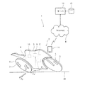
図1は、実施形態に係る走行データ表示システム1の全体図である。図1に示すように、走行データ表示システム1は、自動二輪車2の走行中に得られた走行データに基づいて走行中の自動二輪車2に作用した力を求め、当該力を走行後に携帯情報端末11(例えば、スマートフォン)に画像で表示させ、運転者が自己の運転スキルを評価できるようにするものである。なお、走行データ表示システム1の適用対象は、車体を左右方向に傾斜(リーン)させて旋回するリーン車両である。リーン車両は、運転者と車両とを合わせた移動体全体が遠心力と釣り合う傾斜角で走行することで、車体傾斜状態(リーン姿勢状態)を維持して旋回走行する。自動二輪車2は、そのリーン車両の好適例である。   FIG. 1 is an overall view of a traveling data display system 1 according to the embodiment. As shown in FIG. 1, a traveling data display system 1 obtains a force applied to a traveling motorcycle 2 based on traveling data obtained while the motorcycle 2 is traveling, and calculates the force applied to the portable information terminal after traveling. 11 (for example, a smartphone) as an image so that the driver can evaluate his or her own driving skills. The running data display system 1 is applied to a lean vehicle that turns while leaning the vehicle body in the left-right direction. The lean vehicle turns while maintaining the vehicle body leaning state (lean posture state) by running the entire moving body including the driver and the vehicle at an inclination angle balanced with the centrifugal force. The motorcycle 2 is a preferred example of the lean vehicle.

自動二輪車2は、従動輪である前輪3と、駆動輪である後輪4とを備える。自動二輪車2は、前輪接地点と後輪接地点とを通過する前後軸AX周りに左右方向に車体5を傾斜させた状態(リーン姿勢状態)で旋回走行する。車体5が直立した状態を基準とした前後軸AX周りの車体5の傾斜角をリーン角θという(直立状態のリーン角θはゼロ)。   The motorcycle 2 includes a front wheel 3 that is a driven wheel and a rear wheel 4 that is a driving wheel. The motorcycle 2 turns while the vehicle body 5 is tilted left and right around a front-rear axis AX that passes through a front wheel contact point and a rear wheel contact point (lean posture state). The lean angle of the vehicle body 5 around the longitudinal axis AX with respect to the state in which the vehicle body 5 is upright is referred to as lean angle θ (the lean angle θ in the upright state is zero).

自動二輪車2は、走行用の駆動力を発生する原動機を備える。本実施形態では、原動機としてエンジンE(内燃機関)が採用されるが、エンジンに代えて電動モータを採用してもよいし、エンジン及び電動モータの両方を採用してもよい。エンジンEの駆動力は、動力伝達機構を介して後輪4に付与される。   The motorcycle 2 includes a motor that generates driving force for traveling. In the present embodiment, the engine E (internal combustion engine) is used as the prime mover, but an electric motor may be used instead of the engine, or both the engine and the electric motor may be used. The driving force of the engine E is applied to the rear wheels 4 via a power transmission mechanism.

自動二輪車2は、前輪3及び後輪4を制動する油圧式のブレーキ装置を備える。当該ブレーキ装置は、前輪3を制動する前ブレーキユニット6と、後輪4を制動する後ブレーキユニット7と、前ブレーキユニット6及び後ブレーキユニット7を制御するブレーキ制御ユニット8とを有する。前ブレーキユニット6及び後ブレーキユニット7は、互いに独立して動作し、それぞれブレーキ圧に比例した制動力を前輪3及び後輪4に付与する。   The motorcycle 2 includes a hydraulic brake device that brakes the front wheel 3 and the rear wheel 4. The brake device includes a front brake unit 6 that brakes the front wheel 3, a rear brake unit 7 that brakes the rear wheel 4, and a brake control unit 8 that controls the front brake unit 6 and the rear brake unit 7. The front brake unit 6 and the rear brake unit 7 operate independently of each other, and apply a braking force proportional to the brake pressure to the front wheel 3 and the rear wheel 4, respectively.

自動二輪車2は、車両制御装置9(ECU)を備える。車両制御装置9は、駆動源(例えば、エンジンE)の駆動力を制御するものでよいし、車輪の制動動作を制御(ABS制御)するものでもよいし、車体挙動(サスペンションやステアリング)を制御するものでもよい。車両制御装置9には、車両を制御するために各種センサから検出情報が与えられる。例えば、スロットル開度、車速、エンジン回転数、ブレーキ圧等の検出情報が、車両制御装置9に入力される。   The motorcycle 2 includes a vehicle control device 9 (ECU). The vehicle control device 9 may control the driving force of a driving source (for example, the engine E), may control the braking operation of the wheels (ABS control), or may control the vehicle body behavior (suspension or steering). You may do it. The vehicle control device 9 is provided with detection information from various sensors to control the vehicle. For example, detection information such as a throttle opening, a vehicle speed, an engine speed, and a brake pressure is input to the vehicle control device 9.

路面から前輪3又は後輪4のタイヤに作用する力には、そのタイヤに縦方向(前後方向)に作用する「縦タイヤ力Fx」と、そのタイヤに横方向(左右方向)に作用する「横タイヤ力Fy」と、タイヤに鉛直上向きに作用する「垂直抗力FV」とが含まれる。即ち、駆動輪(後輪4)の縦タイヤ力Fxは、加速時には前方向に向いて減速時には後方向に向く力であり、従動輪(前輪3)の縦タイヤ力Fxは、減速時に後方向に向く力である。 The force acting from a road surface to a tire of the front wheel 3 or rear wheels 4, "vertical tire force F x" acting in the vertical direction (longitudinal direction) on the tire, which acts in the transverse direction (horizontal direction) in the tire The "lateral tire force F y " and the "vertical drag F V " acting vertically upward on the tire are included. That is, the vertical tire force F x of the driving wheels (rear wheels 4), at the time of acceleration is the force directed to the rear direction at the time of deceleration facing forward, vertical tire force F x of the driven wheels (front wheels 3), at the time of deceleration It is a force that turns backward.

後輪4に縦力Fxを発生させる主要因には、エンジンEから後輪4に伝達される駆動力と、後ブレーキユニット7から後輪4に付与される制動力とが挙げられ、前輪3に縦力Fxを発生させる主要因には、前ブレーキユニット6から前輪3に付与される制動力が挙げられる。横タイヤ力Fyは、旋回走行中に発生する。前輪3及び後輪4に横タイヤ力Fyを発生させる主要因には、走行速度及び旋回半径に基づく遠心力の反力が挙げられる。 The main factor causing the Tateryoku F x to the rear wheel 4, a driving force is transmitted to the rear wheel 4 from the engine E, a braking force can be mentioned which is applied to the rear wheel 4 from the rear brake unit 7, the front wheels the main factor that generates Tateryoku F x 3, the braking force can be cited before being applied from the brake unit 6 to the front wheel 3. The lateral tire force Fy is generated during turning. The main factor to generate a lateral tire force F y to the front wheel 3 and rear wheel 4, the reaction force of the centrifugal force based on the traveling speed and the turning radius and the like.

自動二輪車2には、走行状態を検出する後述する各種のセンサが搭載されており、その各センサの検出信号を受信する走行データ管理装置10が搭載されている。自動二輪車2の運転者は、携帯情報端末11(例えば、スマートフォン)を所持するか、あるいは、自動二輪車2の所定の位置に携帯情報端末11を取り付ける。携帯情報端末11は、走行データ管理装置10と通信すると共に、通信ネットワークN(例えば、インターネット)を介して外部のサーバ12及びデータベース13と通信する。   The motorcycle 2 is equipped with various sensors, which will be described later, for detecting a traveling state, and is equipped with a traveling data management device 10 for receiving detection signals from the sensors. The driver of the motorcycle 2 carries the portable information terminal 11 (for example, a smartphone) or attaches the portable information terminal 11 to a predetermined position of the motorcycle 2. The portable information terminal 11 communicates with the traveling data management device 10 and also communicates with the external server 12 and the database 13 via the communication network N (for example, the Internet).

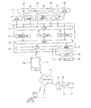
図2は、図1に示す走行データ表示システム1のブロック図である。図2に示すように、走行データ管理装置10の入力側には、GPS受信機21、IMU22、エンジン回転数センサ23、車速センサ24、駆動輪速度センサ25、ブレーキ圧センサ26、リーン角センサ27(リーン姿勢検出装置)及び入力操作器28が接続されている。GPS受信機21は、GPS衛星から自車位置情報を受信する。なお、このGPS受信機21に代えて携帯情報端末11の位置検出機能を用いてもよい。また、GPS受信器21に代えて、速度センサ及び方向センサから移動距離及び方向を累積演算して現在位置座標を取得してもよい。また、走行位置を取得可能であれば、既存の他の検出装置を用いてもよい。   FIG. 2 is a block diagram of the traveling data display system 1 shown in FIG. 2, a GPS receiver 21, an IMU 22, an engine speed sensor 23, a vehicle speed sensor 24, a driving wheel speed sensor 25, a brake pressure sensor 26, a lean angle sensor 27 are provided on the input side of the traveling data management device 10. (Lean posture detecting device) and an input operation device 28 are connected. The GPS receiver 21 receives vehicle position information from a GPS satellite. Note that the position detection function of the portable information terminal 11 may be used instead of the GPS receiver 21. Further, instead of the GPS receiver 21, the moving distance and the direction may be cumulatively calculated from the speed sensor and the direction sensor to obtain the current position coordinates. Further, another existing detection device may be used as long as the traveling position can be acquired.

IMU22は、3軸のジャイロと3方向の加速度計によって、3次元の角速度及び加速度をそれぞれ検出する慣性計測装置であり、互いに直交する3軸方向の加速度と当該3軸回りの角速度とを検出することができる。なお、IMUの代わりに、一般的な加速度センサが用いられてもよい。例えば、携帯情報端末11に加速度センサが搭載されている場合、IMU22の代わりに携帯情報端末11の加速度センサが用いられてもよい。   The IMU 22 is an inertial measurement device that detects a three-dimensional angular velocity and an acceleration by a three-axis gyro and a three-directional accelerometer, respectively, and detects an acceleration in a three-axis direction orthogonal to each other and an angular velocity around the three axes. be able to. Note that a general acceleration sensor may be used instead of the IMU. For example, when an acceleration sensor is mounted on the portable information terminal 11, the acceleration sensor of the portable information terminal 11 may be used instead of the IMU 22.

エンジン回転数センサ23は、エンジンEのクランク軸の回転数を検出する。車速センサ24は、例えば、従動輪である前輪3の回転数を検出することにより自動二輪車2の走行速度を検出する。駆動輪速度センサ25は、駆動輪である後輪4の回転数を検出する。ブレーキ圧センサ26は、前ブレーキユニット6及び後ブレーキユニット7に発生するブレーキ圧力(例えば、ブレーキ油圧)をそれぞれ検出する。リーン角センサ27は、車体5が直立状態から左右方向へ傾斜した角度(リーン角)を検出する。入力操作器28は、運転者が入力操作を行うタッチパネルやボタン等である。   The engine speed sensor 23 detects the speed of the crankshaft of the engine E. The vehicle speed sensor 24 detects the traveling speed of the motorcycle 2 by detecting, for example, the rotation speed of the front wheel 3 that is a driven wheel. The drive wheel speed sensor 25 detects the rotation speed of the rear wheel 4 that is a drive wheel. The brake pressure sensor 26 detects a brake pressure (for example, a brake oil pressure) generated in the front brake unit 6 and the rear brake unit 7. The lean angle sensor 27 detects an angle (lean angle) at which the vehicle body 5 is inclined in the left-right direction from the upright state. The input operation device 28 is a touch panel, a button, or the like on which a driver performs an input operation.

走行データ管理装置10は、ハードウェア面において、プロセッサ、揮発性メモリ、不揮発性メモリ及びI/Oインターフェース等を有する。走行データ管理装置10は、機能面において、入力部31、走行位置履歴取得部32、タイヤ力演算部33(演算装置)、遠心力演算部34(演算装置)、制御部36(制御装置)、記憶部37(記憶装置)及び出力部38を備える。記憶部37は、揮発性メモリ及び不揮発性メモリにより実現される。入力部31及び出力部38は、I/Oインターフェースにより実現される。走行位置履歴取得部32、タイヤ力演算部33及び遠心力演算部34は、不揮発性メモリに保存された走行情報処理プログラムに基づいてプロセッサが揮発性メモリを用いて演算処理することで実現される。制御部36は、不揮発性メモリに保存された走行データ処理プログラムに基づいてプロセッサが揮発性メモリを用いて演算処理することで実現される。   The traveling data management device 10 includes a processor, a volatile memory, a nonvolatile memory, an I / O interface, and the like in terms of hardware. In terms of functions, the traveling data management device 10 includes an input unit 31, a traveling position history acquiring unit 32, a tire force computing unit 33 (computing device), a centrifugal force computing unit 34 (computing device), a control unit 36 (control device), A storage unit 37 (storage device) and an output unit 38 are provided. The storage unit 37 is realized by a volatile memory and a nonvolatile memory. The input unit 31 and the output unit 38 are realized by an I / O interface. The traveling position history acquiring unit 32, the tire force computing unit 33, and the centrifugal force computing unit 34 are realized by the processor performing the arithmetic processing using the volatile memory based on the traveling information processing program stored in the nonvolatile memory. . The control unit 36 is realized by the processor performing an arithmetic process using a volatile memory based on a traveling data processing program stored in a nonvolatile memory.

位置履歴取得部32は、GPS受信機21で検出される自動二輪車2の位置情報から自動二輪車2の走行位置の履歴を求める。なお、走行位置履歴は、自動二輪車2の走行軌跡でもよいし、自動二輪車2の走行した位置座標でもよい。タイヤ力演算部33は、後述するように前輪3及び後輪4の各々にかかる横タイヤ力Fyを求める。遠心力演算部34は、後述するように旋回走行時に車体5にかかる遠心力を求める。制御部36は、位置履歴取得部32、タイヤ力演算部33、及び遠心力演算部34で得られた走行データを記憶部37に書込みすると共に、当該走行データを記憶部37から読み出して出力部38を介して携帯情報端末11又は表示器39に表示させる。なお、制御部36は、出力部38を介して走行データを外部メモリ40にも記憶させることが可能である。 The position history obtaining unit 32 obtains a history of the running position of the motorcycle 2 from the position information of the motorcycle 2 detected by the GPS receiver 21. The traveling position history may be a traveling locus of the motorcycle 2 or the coordinates of a position at which the motorcycle 2 has traveled. Tire force calculating unit 33 obtains the lateral tire force F y according to each of the front wheel 3 and rear wheel 4, as described later. The centrifugal force calculation unit 34 calculates the centrifugal force applied to the vehicle body 5 during turning as described later. The control unit 36 writes the traveling data obtained by the position history acquiring unit 32, the tire force computing unit 33, and the centrifugal force computing unit 34 into the storage unit 37, reads the traveling data from the storage unit 37, and outputs the traveling data. The information is displayed on the portable information terminal 11 or the display 39 via the display 38. Note that the control unit 36 can also store the traveling data in the external memory 40 via the output unit 38.

出力部38は、自動二輪車2の運転者が所有する携帯情報端末11に近距離無線通信(例えば、Bluetooth(登録商標))によりデータを送信する。携帯情報端末11は、走行データを表示するためのアプリケーションプログラムを有し、そのプログラムに従ってネットワークNを介して遠隔地のサーバ12及びデータベース13との間でデータを送受信可能である。サーバ12は、自動二輪車2と同様に他のユーザの自動二輪車の携帯情報端末と通信し、データベース13には多数のユーザの走行データが蓄積される。   The output unit 38 transmits data to the portable information terminal 11 owned by the driver of the motorcycle 2 by short-range wireless communication (for example, Bluetooth (registered trademark)). The portable information terminal 11 has an application program for displaying travel data, and can transmit and receive data to and from the remote server 12 and the database 13 via the network N according to the program. The server 12 communicates with the portable information terminals of the motorcycles of other users as in the case of the motorcycle 2, and the database 13 stores travel data of many users.

携帯情報端末11は、ハードウェア面において、演算部(CPU)と、入力インターフェース(アンテナ、ボタン等)と、記憶部(ROM/RAM)と、出力インターフェース(表示画面50)とを有する。携帯情報端末11は、例えばスマートフォンであり得る。携帯情報端末11は、自動二輪車2に搭載された走行データ管理装置10から受信した情報に基づき、その表示画面50に後述する力画像及び車両画像を同時に表示する。   The portable information terminal 11 has, in terms of hardware, an arithmetic unit (CPU), an input interface (antenna, buttons, and the like), a storage unit (ROM / RAM), and an output interface (display screen 50). The portable information terminal 11 can be, for example, a smartphone. The portable information terminal 11 displays a later-described force image and a vehicle image on its display screen 50 based on information received from the traveling data management device 10 mounted on the motorcycle 2.

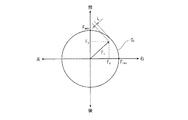
図3は、後輪4の摩擦円を示す平面図である。図3に示すように、後輪4の摩擦円Cfは、路面に対する後輪4のタイヤのグリップ限界を示す円である。即ち、摩擦円Cfは、鉛直方向に垂直な水平面上において後輪接地点を中心とし、最大摩擦力(路面と後輪との間の摩擦係数μと後輪タイヤの垂直抗力Fvとの積μ・Fv)の大きさを半径とする円である。後輪4と路面との間に生じるタイヤ力は、後輪4の進行方向成分である縦タイヤ力Fxと、当該進行方向に直交する横方向成分である横タイヤ力Fyとを有する。 FIG. 3 is a plan view showing a friction circle of the rear wheel 4. As shown in FIG. 3, the friction circle C f of the rear wheel 4 is a circle showing the grip limit of the tires of the rear wheels 4 with respect to the road surface. That is, the friction circle C f is defined by a maximum frictional force (the coefficient of friction μ between the road surface and the rear wheel and the vertical drag F v of the rear wheel tire) centered on the rear wheel contact point on a horizontal plane perpendicular to the vertical direction. It is a circle whose radius is the size of the product μ · F v ). Tire force generated between the rear wheels 4 and the road surface has a longitudinal tire force F x is a traveling direction component of the rear wheel 4, and a lateral tire force F y is a lateral component perpendicular to the direction of travel.

縦タイヤ力Fxと横タイヤ力Fyとの合力Ftの起点は摩擦円Cfの中心にあり、合力Ftの終点が摩擦円Cfの内側に収まっているときには、合力Ftが摩擦力と釣り合い得るので、後輪4のスリップが防がれる。合力Ftが摩擦円Cfを超えるときには、合力Ftが最大摩擦力よりも大きいので、後輪4が最大摩擦力に抗してスリップする。即ち、合力Ftの終点が摩擦円Cfの内側にあるときにおける合力Ftの終点と摩擦円Cfとの間の距離Lに相関する値が、後輪4の路面に対する滑りが発生するまでの余裕度FSとして設定される。余裕度FSは、例えば、試験結果等に基づいて、合力Ftの終点と摩擦円Cfとの距離Lを段階的に表した値に設定されてもよい。例えば、距離Lごとに5段階のレベルが予め設定されてもよい。また、摩擦円Cfの半径をFmaxとした場合には、余裕度FSは、L/Fmaxとしてもよい。 Origin of the resultant force F t of the vertical tire force F x and the lateral tire force F y is in central friction circle C f, when the end point of the resultant force F t is within the interior of the friction circle C f is the resultant force F t is Since it can be balanced with the frictional force, the rear wheel 4 is prevented from slipping. When the resultant force F t is greater than the friction circle C f is the resultant force F t is is larger than the maximum friction force, the rear wheel 4 from slipping against the maximum friction force. That is, the value of the end point of the resultant force F t is correlated to the distance L between the end points and friction circle C f of the resultant force F t in the time inside the friction circle C f is slipping relative to the road surface of the rear wheel 4 is generated Is set as the margin FS up to. Margin FS is, for example, test results, etc. Based on the distance L between the end points and friction circle C f of the resultant force F t may be set in stages to a value expressed. For example, five levels may be set in advance for each distance L. Moreover, the radius of the friction circle C f in the case of the F max, the margin FS, may be L / F max.

本実施形態では、タイヤ力演算部33は、自動二輪車2に作用する力としての後輪4の横タイヤ力Fy及び縦タイヤ力Fxを算出する。横タイヤ力Fyは、旋回走行中に主に走行速度及び旋回半径に基づく遠心力の反力として発生し、車体バンク角β(=90°−θ)の時間変化に関連する値(例えば、バンク角速度やバンク角加速度)に応じて発生する成分を含む。そのため、横タイヤ力Fyは、IMU22で検出される横加速度とバンク角とを入力とした関数として求めることができる。例えば、横タイヤ力Fyは、横加速度及びバンク角の各々が増加するにつれて増加する関数により算出できる。横タイヤ力Fyの向きは、横加速度の向きと同じである。 In the present embodiment, the tire force calculation unit 33 calculates the lateral tire force F y, and the vertical tire force F x rear wheels 4 as the force acting on the motorcycle 2. The lateral tire force Fy is generated as a reaction force of the centrifugal force mainly based on the traveling speed and the turning radius during cornering, and is a value related to the time change of the vehicle body bank angle β (= 90 ° −θ) (for example, (A bank angular velocity and a bank angular acceleration). Therefore, lateral tire force F y can be determined as a function as input the lateral acceleration and the bank angle detected by IMU22. For example, lateral tire force F y can be calculated by a function which increases as each of the lateral acceleration and the bank angle increases. Orientation of the lateral tire force F y is the same as the lateral acceleration of the orientation.

縦タイヤ力Fxは、車輪に付与された駆動力及び制動力の反力として発生する。そのため、縦タイヤ力Fxは、エンジン回転数とブレーキ圧とを入力とした関数として求めることができる。例えば、縦タイヤ力Fxは、後方に向けた力を正値として前方に向けた力を負値とした場合には、エンジン回転数が増加するにつれて増加し且つブレーキ圧が増加するにつれて減少する関数により算出できる。 The vertical tire force Fx is generated as a reaction force between the driving force and the braking force applied to the wheels. Therefore, the vertical tire force F x can be determined as a function that inputs the engine speed and the brake pressure. For example, the vertical tire force F x is, when a force directed to the forward force toward the rear as a positive value and a negative value decreases as increase and braking pressure as the engine speed increases to increase It can be calculated by a function.

なお、前記した縦タイヤ力Fx及び横タイヤ力Fyの求め方は一例である。タイヤ力演算部33は、遠心力等の力の釣り合いによる運動方程式から求められる他の既知の計算式を用いてタイヤ力を演算してもよい(WO2018/073912)。またタイヤ力演算部33は、具体的にタイヤに作用する力をセンサによって検出した情報に基づいて取得してもよい。例えば、タイヤ力について、特開2017-161395号公報に開示されたように、ホイールに取り付けられてタイヤに作用する力を検出するひずみゲージに基づいて、取得してもよい。 Incidentally, how to obtain the vertical tire force F x and the lateral tire force F y described above is an example. The tire force calculation unit 33 may calculate the tire force using another known calculation formula obtained from the equation of motion based on the balance of the force such as the centrifugal force (WO2018 / 073912). Further, the tire force calculation unit 33 may specifically acquire the force acting on the tire based on information detected by a sensor. For example, the tire force may be obtained based on a strain gauge attached to a wheel and detecting a force acting on the tire, as disclosed in Japanese Patent Application Laid-Open No. 2017-161395.

遠心力演算部34は、自動二輪車2に作用する力としての遠心力FcをIMU22及びリーン角センサ27の検出信号から求める。具体的には、車体5がリーン状態にあるときはIMU22の検出方向も車体5と一体に水平面に対して傾斜するため、Fc=m・αの数式4で遠心力Fcを算出する。mは、車体5の質量である。このように、横加速度は、遠心力Fcに関連する力関連値であり、IMU22は、力関連値検出装置である。なお、遠心力は、走行軌跡(カーブ軌跡)の曲率及び車速データから算出されてもよい。又は、遠心力は、IMU22で検出されたヨー方向の加速レート及びロール方向の加速レートに基づいて算出されてもよい。 Centrifugal force operating section 34 calculates the centrifugal force F c of the forces acting on the motorcycle 2 from IMU22 and the detection signal of the lean angle sensor 27. Specifically, the vehicle body 5 when in the lean state to inclined relative to a horizontal plane integrally with the detection direction the vehicle body 5 of IMU22, calculates a centrifugal force F c in Equation 4 F c = m · α. m is the mass of the vehicle body 5. Thus, the lateral acceleration is the force related value related to the centrifugal force F c, IMU22 is a force-related value detection device. The centrifugal force may be calculated from the curvature of the traveling locus (curve locus) and vehicle speed data. Alternatively, the centrifugal force may be calculated based on the acceleration rate in the yaw direction and the acceleration rate in the roll direction detected by the IMU 22.

遠心力Fcの演算方法は一例であって、他の演算式で遠心力を求めてもよい。例えば、特開2017−65561号公報に開示されたように車両及び運転者を含む移動体全体の車幅方向の傾斜角(移動体リーン角)に釣り合う力を遠心力として求めてもよい。 Calculation method of the centrifugal force F c is an example, it may be obtained centrifugal force in other expression. For example, as disclosed in Japanese Unexamined Patent Application Publication No. 2017-65561, a centrifugal force may be obtained as a force that balances an inclination angle (moving body lean angle) of the entire moving body including the vehicle and the driver in the vehicle width direction.

走行データ管理装置10の制御部36は、タイヤ力演算部33で求められたタイヤ力Ft(Fy,Fx)及び/又は遠心力演算部34で求められた遠心力Fcを、位置履歴取得部32で取得された走行位置履歴に関連付けて所定の間隔(例えば、一定距離ごと又は一定時間ごと)ごとに記憶部37に記憶させる。また、制御部36は、車体5のリーン姿勢に関する情報も走行位置履歴に関連付けて前記所定の間隔ごとに記憶部37に記憶させる。例えば、制御部36は、車体5が所定のリーン角以上のリーン姿勢になったことを示す情報又はリーン角自体を走行位置履歴に関連付けて記憶部37に記憶させる。即ち、横タイヤ力Fy及び/又は遠心力Fcは、走行位置履歴の情報を介してリーン姿勢に関する情報に関連付けられる。また、制御部36は、前記した余裕度FSも走行位置の情報に関連付けて記憶部37に記憶させる。 The control unit 36 of the traveling data management device 10 calculates the position of the tire force F t (F y , F x ) determined by the tire force calculation unit 33 and / or the centrifugal force F c determined by the centrifugal force calculation unit 34. The storage unit 37 stores the travel position history acquired by the history acquisition unit 32 at predetermined intervals (for example, every fixed distance or every certain time) in association with the travel position history. Further, the control unit 36 causes the storage unit 37 to store information on the lean posture of the vehicle body 5 in association with the travel position history at each of the predetermined intervals. For example, the control unit 36 causes the storage unit 37 to store information indicating that the vehicle body 5 has a lean posture equal to or greater than a predetermined lean angle or the lean angle itself in association with the travel position history. That is, the lateral tire force Fy and / or the centrifugal force Fc are associated with the information on the lean posture through the information on the traveling position history. The control unit 36 also causes the storage unit 37 to store the above-mentioned margin FS in association with the information on the traveling position.

制御部36は、記憶部37に記憶された情報を出力部38から出力させ、携帯情報端末11及びネットワークNを介してサーバ12に送信してデータベース13に蓄積させる。走行データ管理装置10から携帯情報端末11を介してサーバ12に送信されるデータには、送信元の自動二輪車2及び運転者の各識別情報が付加されている。自動二輪車2の識別情報は、走行データ管理装置10に予め記憶されている。運転者の識別情報は、例えば、携帯情報端末11に登録されている。   The control unit 36 outputs the information stored in the storage unit 37 from the output unit 38, transmits the information to the server 12 via the portable information terminal 11 and the network N, and stores the information in the database 13. The data transmitted from the traveling data management device 10 to the server 12 via the portable information terminal 11 is added with identification information of the motorcycle 2 and the driver of the transmission source. The identification information of the motorcycle 2 is stored in the travel data management device 10 in advance. The identification information of the driver is registered in the portable information terminal 11, for example.

サーバ12には、各自動二輪車又はそれら運転者の識別情報を取得する識別情報取得部14が設けられ、サーバ12にインストールされたプログラムは、種々の走行分析を行い、出力制御部15により当該識別情報ごとにタイヤ力Ft(Fy,Fx)及び遠心力Fcを含む各種走行情報や分析結果等を走行位置に関連付けた状態で携帯情報端末11に表示させることが可能である。また携帯情報端末11に走行データに関する情報を走行後に表示させる情報は、走行データ管理装置10の出力部38から送られてもよいし、サーバ12の出力制御部15から送られてもよい。 The server 12 is provided with an identification information acquisition unit 14 for acquiring identification information of each motorcycle or their driver. A program installed in the server 12 performs various running analyzes, and the output control unit 15 performs the identification. it is possible to display on the mobile information terminal 11 in a state where the associated tire force F t (F y, F x ) a and centrifugal force F c various travel information and analysis results and the like to the traveling position every information. The information for causing the portable information terminal 11 to display the information on the travel data after traveling may be sent from the output unit 38 of the travel data management device 10 or may be sent from the output control unit 15 of the server 12.

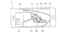
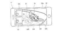
図4は、図2に示す携帯情報端末11の表示画面50の第1例を示す図面である。携帯情報端末11は、走行データを表示するための表示装置として機能する。携帯情報端末11は、走行データを表示するためのアプリケーションプログラムとして走行データ表示プログラムを有する。当該走行データ表示プログラムは、ユーザ(運転者)の入力に応じて、走行データ管理装置10又はサーバ12から受信した情報を処理して携帯情報端末11の表示画面50に所望の表示を行わせる。ユーザが携帯情報端末11を操作して過去の走行データのタイヤ力の表示を要求すると、表示画面50は図4に示すような表示が行われる。   FIG. 4 is a drawing showing a first example of the display screen 50 of the portable information terminal 11 shown in FIG. The portable information terminal 11 functions as a display device for displaying travel data. The portable information terminal 11 has a traveling data display program as an application program for displaying traveling data. The traveling data display program processes information received from the traveling data management device 10 or the server 12 according to an input of a user (driver) and causes a desired display to be performed on the display screen 50 of the portable information terminal 11. When the user operates the portable information terminal 11 to request the display of the tire power of the past traveling data, the display screen 50 displays as shown in FIG.

本実施形態の表示画面50は、複数のセグメント50a,50bに分割されている。但し、表示画面50は複数のセグメントに分割されずに単一の画面としてもよい。表示画面50の1つのセグメントである動画領域50aには、自動二輪車2を示す車両画像51と、受信した走行データに基づいてタイヤ力を示す力画像52A,52Bとが一緒に重ねて表示されている。   The display screen 50 of the present embodiment is divided into a plurality of segments 50a and 50b. However, the display screen 50 may be a single screen without being divided into a plurality of segments. In a moving image area 50a, which is one segment of the display screen 50, a vehicle image 51 indicating the motorcycle 2 and force images 52A and 52B indicating tire force based on the received traveling data are displayed together and superimposed. I have.

車両画像51は、対象とする車両、例えば自動二輪車2の画像を含む。本実施形態では、車両画像51は、車両を前方かつ左右方向一方側から見た画像として表示される。即ち、車両の前方面及び一方の側方面を示す斜視図として表示される。車両画像51は、自動二輪車2の旋回時における車体5のリーン姿勢を反映させて表示される。即ち、車両画像51上において、自動二輪車2が直進走行しているときには車体5が直立状態で表示され、自動二輪車2が旋回走行しているときには車体5がリーン姿勢で表示される。   The vehicle image 51 includes an image of a target vehicle, for example, the motorcycle 2. In the present embodiment, the vehicle image 51 is displayed as an image of the vehicle viewed from the front and one side in the left-right direction. That is, it is displayed as a perspective view showing the front surface and one side surface of the vehicle. The vehicle image 51 is displayed reflecting the lean posture of the vehicle body 5 when the motorcycle 2 turns. That is, on the vehicle image 51, when the motorcycle 2 is traveling straight, the vehicle body 5 is displayed in an upright state, and when the motorcycle 2 is turning, the vehicle body 5 is displayed in a lean posture.

例えば、リーン角θに応じて複数用意される右リーン状態の車両をそれぞれ示す複数種類の車体画像と、リーン角θに応じて複数用意される左リーン状態の車両をそれぞれ示す複数種類の車体画像とが携帯情報端末11に記憶されている。携帯情報端末11は、走行データ管理装置10から受信したリーン角θの情報に基づいて、適切な車体画像51aを選択して表示する。   For example, a plurality of types of vehicle images each showing a plurality of right lean vehicles prepared according to the lean angle θ, and a plurality of types of vehicle images each showing a plurality of left lean vehicles prepared according to the lean angle θ Are stored in the portable information terminal 11. The portable information terminal 11 selects and displays an appropriate vehicle body image 51a based on the information on the lean angle θ received from the traveling data management device 10.

また本実施形態では、車両画像51は、自動二輪車2の背景の画像を含んでいる。背景の画像として、路面画像51bと路面外画像51cとが表示される。路面画像51bとして、直進路/曲線路に関する情報や走行路の曲率半径に応じて複数用意される路面画像とが携帯情報端末11に記憶されている。携帯情報端末11は、受信した位置情報や走行軌跡情報に基づいて適切な路面画像51bを選択して表示する。路面外画像51cとしては、予め定める初期画面が携帯情報端末11に記憶されている。例えば、路面外画像51cとして、走行時間帯(日中、夜間、早朝、夕方等)ごとに異なる画像が記憶されてもよいし、天候情報(雨天、曇天、晴天等)、走行路情報(高速道路、市街地、サーキット、ドライブウェイ等)などに応じて画像が記憶されてもよい。このような情報は、GPSや通信ネットワークNを介して得られるサーバ12の情報に基づいて入手することができる。   In the present embodiment, the vehicle image 51 includes an image of the background of the motorcycle 2. As a background image, a road surface image 51b and an off-road image 51c are displayed. As the road surface image 51b, information on a straight road / curved road and a plurality of road surface images prepared according to the radius of curvature of the traveling road are stored in the portable information terminal 11. The portable information terminal 11 selects and displays an appropriate road surface image 51b based on the received position information and traveling locus information. As the out-of-road image 51c, a predetermined initial screen is stored in the portable information terminal 11. For example, as the off-road image 51c, a different image may be stored for each traveling time zone (day, night, early morning, evening, etc.), weather information (rainy weather, cloudy weather, fine weather, etc.), traveling road information (high speed) Images may be stored according to roads, city areas, circuits, driveways, and the like. Such information can be obtained based on information of the server 12 obtained via the GPS or the communication network N.

携帯情報端末11は、路面外画像51c、路面画像51b、車体画像51aの順(即ち、車両画像が最表面となる順で)で合成し、その合成画像を車両画像51として動画領域50aに表示する。具体的には、自動二輪車画像が一番前面に見えるように車両画像51を生成する。これによって前方で且つ左右方向一方の斜め位置から車両を撮影した画像を模した画像を生成することができる。   The portable information terminal 11 synthesizes in the order of the off-road image 51c, the road image 51b, and the vehicle body image 51a (that is, in the order in which the vehicle image is the outermost surface), and displays the synthesized image as the vehicle image 51 in the moving image area 50a. I do. Specifically, the vehicle image 51 is generated so that the motorcycle image can be seen in the foreground. As a result, it is possible to generate an image imitating an image obtained by photographing the vehicle from the front and one oblique position in the left-right direction.

力画像52Aは、自動二輪車2の後輪4のタイヤに作用する後輪タイヤ力を示す前輪タイヤ力画像である。力画像52Bは、自動二輪車2の前輪3のタイヤに作用する前輪タイヤ力を示す前輪タイヤ力画像である。なお、力画像52が表示する力は、自動二輪車2の走行データに基づいて求められる走行中に自動二輪車2に作用した力であればタイヤ力に限られず、例えば自動二輪車2に作用する遠心力Fcでもよい。 The force image 52A is a front wheel tire force image indicating the rear wheel tire force acting on the tire of the rear wheel 4 of the motorcycle 2. The force image 52B is a front wheel tire force image showing the front wheel tire force acting on the tire of the front wheel 3 of the motorcycle 2. The force displayed by the force image 52 is not limited to the tire force as long as it is a force acting on the motorcycle 2 during traveling determined based on the traveling data of the motorcycle 2, and for example, a centrifugal force acting on the motorcycle 2 It may be F c.

力画像52A,52Bは、車両に作用した力を可視化して表したものである。力画像52A,52Bは、数値や文字とは異なる非文字情報であることが好ましい。具体的には、力画像52A,52Bは、色、形状、大きさ、向きなどの画像として認識される情報の視覚的変化によって表される。これにより、数値や文字で力を表す場合に比べ、走行状態を直感的に認識しやすくすることができる。   The force images 52A and 52B visualize and represent the force acting on the vehicle. The force images 52A and 52B are preferably non-character information different from numerical values and characters. Specifically, the force images 52A and 52B are represented by visual changes in information recognized as images such as color, shape, size, and orientation. This makes it easier to intuitively recognize the running state as compared to the case where the force is represented by numerical values or characters.

具体的には、各タイヤ力画像52A,52Bは、対応する車輪と路面との間の接点を中心とした楕円としてそれぞれ描かれ、タイヤ力の大きさを楕円形の大きさ(面積)により表現している。本実施形態では、各タイヤ力画像52A,52Bは、縦タイヤ力Fxを自動二輪車2の前後方向の軸とし、横タイヤ力Fyを自動二輪車2の左右方向の軸とした楕円形状である。したがって、その楕円形状、すなわち長軸及び短軸の長さによって、タイヤ力の向き(縦タイヤ力と横タイヤ力のベクトル和)として表される。例えば、力画像52A,52Bは、横タイヤ力Fyと縦タイヤ力Fxとが互いに等しいときは真円となることで、タイヤ力の向きについて認識することができる。後輪タイヤ力画像52Aと前輪タイヤ力画像52Bとは、互いに重ねて表示可能である。後輪タイヤ力画像52Aと前輪タイヤ力画像52Bとは、互いに区別して視認可能な態様(例えば、異なる色)で表示される。 Specifically, each of the tire force images 52A and 52B is drawn as an ellipse centered on the contact point between the corresponding wheel and the road surface, and the magnitude of the tire force is represented by the size (area) of the ellipse. doing. In this embodiment, each tire force images 52A, 52B is a longitudinal tire force F x and longitudinal axis of the motorcycle 2, is an elliptical shape with a horizontal direction of the axis of the motorcycle 2 lateral tire force F y . Therefore, the direction of the tire force (the vector sum of the vertical tire force and the lateral tire force) is represented by the elliptical shape, that is, the length of the major axis and the minor axis. For example, the force picture 52A, 52B, when the lateral tire force F y and vertical tire force F x are equal to each other by a perfect circle, it is possible to recognize the orientation of the tire force. The rear wheel tire force image 52A and the front wheel tire force image 52B can be displayed so as to overlap each other. The rear tire force image 52A and the front wheel force image 52B are displayed in a distinguishable and visible manner (for example, in different colors).

携帯情報端末11は、走行位置変化、走行時間変化などの走行状態の変化に伴って車両画像51および各タイヤ力画像52A,52Bが変化するよう動画表示、いわゆるアニメーション表示するように表示画面50を制御する。すなわち走行状態の変化ごとに、走行状態に応じて記憶される画像が順次選択されて表示される。言い換えると、各タイヤ力画像52A,52Bは、車両画像51の変化に伴って動的に変化するように表示される。即ち、車両画像51が表示する自動二輪車2の走行位置の変化に伴って(車両画像51が表示する自動二輪車2の進行に伴って)、当該走行位置に関連付けられたタイヤ力が各タイヤ力画像52A,52Bに表示される。   The portable information terminal 11 displays the display screen 50 so that the vehicle image 51 and the tire force images 52A and 52B change as the running state changes such as the running position change and the running time change. Control. That is, each time the running state changes, the images stored according to the running state are sequentially selected and displayed. In other words, each of the tire force images 52A and 52B is displayed so as to dynamically change with a change in the vehicle image 51. That is, with the change in the traveling position of the motorcycle 2 displayed by the vehicle image 51 (with the progress of the motorcycle 2 displayed by the vehicle image 51), the tire force associated with the traveling position is changed to each tire force image. It is displayed on 52A and 52B.

表示画面50の別のセグメントであるグラフ領域50bには、走行データに関する詳細データ画像53が表示される。例えば、図4の例では、前輪3及び後輪4のタイヤ力の大きさがグラフ表示されている。図4の例では、当該グラフには、横タイヤ力Fyと縦タイヤ力Fxとの合力Ftの大きさが表示されているが、横タイヤ力Fy及び縦タイヤ力Fxの夫々の大きさが個別に表示されてもよい。 In the graph area 50b, which is another segment of the display screen 50, a detailed data image 53 relating to the traveling data is displayed. For example, in the example of FIG. 4, the magnitude of the tire force of the front wheel 3 and the rear wheel 4 is displayed in a graph. In the example of FIG. 4, in the graph, although the magnitude of the resultant force F t of the lateral tire force F y and vertical tire force F x is displayed, the lateral tire force F y, and the vertical tire force F x, respectively May be displayed individually.

また、グラフ領域50bは、色が変化するように表示されてもよい。具体的には、グラフ領域50bのグラフは、力が小さい場合には、青色であり、力が大きくなるにつれて、緑色、黄色、橙色、赤色と色が順番にグラデーション変化してもよい。好ましくは、グラフ領域50bの色とグラフの長さとで力の大きさが表現されることが好ましい。また、力の大きさを表すグラフ領域50bのグラフの色に合わせて、動画領域50aに示される楕円の色が着色されてもよい。この場合、たとえば前輪のタイヤ力として、グラフ領域50bの前輪タイヤ力の大きさを表すグラフが黄色で表される場合、動画領域50aに示される前輪タイヤ力の領域を表す色が同色、すなわち黄色で表される。同様に、後輪のタイヤ力として、グラフ領域50bの後輪タイヤ力の大きさを表すグラフが赤色で表される場合、動画領域50aに示される後輪タイヤ力の領域を表す色が同色、すなわち赤色で表される。言い換えると、動画領域50aのタイヤ力は、力が小さい場合には、青色であり、力が大きくなるにつれて面積が広がるとともに、緑色、黄色、橙色、赤色と色が順番にグラデーション変化することになる。   Further, the graph area 50b may be displayed such that the color changes. Specifically, the graph in the graph region 50b is blue when the force is small, and the gradation may change in the order of green, yellow, orange, and red as the force increases. Preferably, the magnitude of the force is expressed by the color of the graph area 50b and the length of the graph. Further, the color of the ellipse shown in the moving image region 50a may be colored according to the color of the graph in the graph region 50b representing the magnitude of the force. In this case, for example, when the graph representing the magnitude of the front wheel tire force in the graph region 50b is represented by yellow as the front wheel tire force, the color representing the region of the front wheel tire force shown in the moving image region 50a is the same color, that is, yellow. It is represented by Similarly, when the graph representing the magnitude of the rear wheel tire force in the graph area 50b is represented in red as the rear wheel tire force, the color representing the area of the rear wheel tire force shown in the moving image area 50a is the same color, That is, it is represented in red. In other words, when the force is small, the tire force of the moving image area 50a is blue, and the area increases as the force increases, and the color changes gradually in the order of green, yellow, orange, and red. .

以上に説明した形態によれば、走行中に実際に車両に作用した力を力画像52A,52Bとして可視化し、それを車両画像51と共に表示することで、運転者による走行状態の認識を容易にすることができる。また、力画像52A,52Bは、力の大きさを可視化する表示であるので、運転者が車両に作用した力の情報を的確に認識することができる。また、力画像52A,52Bは、車両の車輪に路面から作用する力の情報を含むので、走行中の車輪が空転するまでの余裕度FSを認識しやすくすることができる。また、前輪の力情報と後輪の力情報とが別々に表示されることで、それぞれの力を容易に把握することができる。また、力画像52A,52Bは、走行状態の変化に応じて表示状態が変化するので、力の時間変化を視覚的に把握でき、過渡的な状況変化を容易に認識することができる。また、車両画像51は、旋回走行時に車両をリーン姿勢で表示するので、車両のリーン姿勢に応じた力の変化を容易に認識することができる。   According to the embodiment described above, the force actually applied to the vehicle during traveling is visualized as the force images 52A and 52B, and is displayed together with the vehicle image 51, so that the driver can easily recognize the traveling state. can do. Further, since the force images 52A and 52B are displays for visualizing the magnitude of the force, the driver can accurately recognize information on the force applied to the vehicle. In addition, since the force images 52A and 52B include information on the force acting on the wheels of the vehicle from the road surface, it is possible to easily recognize the margin FS before the running wheels idle. Further, since the front wheel force information and the rear wheel force information are separately displayed, each force can be easily grasped. In addition, since the display state of the force images 52A and 52B changes according to the change of the running state, the time change of the force can be visually grasped, and the transient situation change can be easily recognized. In addition, since the vehicle image 51 displays the vehicle in a lean posture during turning, the change in force according to the lean posture of the vehicle can be easily recognized.

タイヤ力が摩擦限界内に維持されることで、スリップが防がれた走行が可能であるため、運転者は、タイヤ力を視覚で確認することで、タイヤ力を大きくしてもスリップまで余裕があるかどうかを判断することができ、運転の復習に極めて有効となる。例えば、サーキットなどでは、タイヤ力を大きくする余裕があるようであれば、次回の走行についてさらに加減速を高めることができ、走行タイムの短縮化を図り易い。   By keeping the tire force within the friction limit, it is possible to run with slip prevented, so the driver can visually check the tire force so that even if the tire force is increased, the driver has enough time to slip. It is possible to judge whether there is, and it is extremely effective for driving review. For example, in a circuit or the like, if there is room to increase the tire force, acceleration / deceleration can be further increased for the next run, and the running time can be easily reduced.

縦タイヤ力と横タイヤ力との両方を認識可能とすることで、どちらのほうがスリップに対する影響が大きいかを認識することができ、スリップを抑える走行操作を認識しやすくできる。たとえば横タイヤ力のほうがスリップに与える余裕度に影響がある場合には、横タイヤ力を下げることで、スリップに対する余裕度を得ることができる。また逆に摩擦限界に近い状況までタイヤ力を利用しようとした場合には、縦タイヤ力および横タイヤ力をどの程度高めることができるかを認識しやすくすることができる。   By making it possible to recognize both the vertical tire force and the lateral tire force, it is possible to recognize which one has a greater effect on the slip, and it is easier to recognize the traveling operation for suppressing the slip. For example, when the lateral tire force affects the margin given to the slip, the lateral tire force can be reduced to obtain the margin for the slip. Conversely, when the tire force is to be used up to a situation near the friction limit, it is possible to easily recognize how much the vertical tire force and the lateral tire force can be increased.

また、走行後に携帯情報端末11を用いて走行データを確認することができるので、走行状態を認識しやすい。また、通常は目で見えない力を画像表示することで、力のかかり方を意識して次回の運転にフィードバックし易い。また、画像表示で力を表すことで、直感的に認識しやすい。携帯情報端末11によって情報が保存・表示されることで、車両から離れた位置でも走行データを表示でき、走行状態の把握が簡便になると共に、通信ネットワークNを介して他の運転者とのコミュニケーションも図れることができる。また、自身の走行データを外部記憶装置に記憶させたり、携帯情報端末11から通信ネットワークNを介して他者に転送して他者からアドバイスを受けることができる。   In addition, since traveling data can be confirmed using the portable information terminal 11 after traveling, it is easy to recognize the traveling state. In addition, by displaying an image of a force that is normally invisible to the eyes, it is easy to give feedback to the next driving with awareness of how the force is applied. In addition, by expressing the force in the image display, it is easy to recognize intuitively. By storing and displaying the information by the portable information terminal 11, the traveling data can be displayed even at a position distant from the vehicle, the traveling state can be easily grasped, and communication with other drivers via the communication network N can be performed. Can also be planned. Further, the user can store his / her own travel data in an external storage device or transfer the travel data from the portable information terminal 11 to another person via the communication network N to receive advice from the other person.

また、力画像及び車両画像がアニメーション表示されることで、時間的に前後の走行状態も含めて運転を把握することができ、力のかかるタイミングや力をかけるタイミングを認識しやすい。また、記憶されているデータを表示するため、反復確認が可能であり、タイヤ力の変化を十分に認識しやすくなる。また、表示画面50には、旋回走行中の車両をリーン姿勢で表示するため、タイヤ力、特に横タイヤ力を一緒に合わせて表示させることで、タイヤ力に対するリーン姿勢変化の影響を運転者が把握しやすい。   In addition, since the force image and the vehicle image are displayed as animations, it is possible to grasp the driving including the running state before and after the time, and it is easy to recognize the timing of applying the force and the timing of applying the force. In addition, since the stored data is displayed, repetition confirmation is possible, and it becomes easy to sufficiently recognize a change in tire force. In addition, since the display screen 50 displays the vehicle that is turning and turning in a lean posture, the tire force, particularly the lateral tire force, is displayed together, so that the driver can see the influence of the lean posture change on the tire force. Easy to grasp.

また、本実施形態では、縦タイヤ力および横タイヤ力の大きさを、楕円表示の長軸及び短軸として表現するので、縦タイヤ力と横タイヤ力とのそれぞれを把握することができる。また、上述のように大きさ(形状)及び色(色調)の両方で力の大きさが表現されるので、どちらか一方で表現される場合に比べて、さらに視覚的に認識しやすくすることができる。また、力画像で表現される色は、タイヤ力が増加して摩擦限界に近づくにつれて、光のスペクトルにおいて危険色として認識されやすい赤色側に近づく。これによってスリップ限界に近づいていることを運転者に直感的に認識させやすくすることができる。また、車両を斜めから見た車両画像51を表示することで、車両の正面視または背面視による画像に比べて、前輪と後輪の路面との接地点をずらして表示することができる。これによって前輪及び後輪それぞれのタイヤ力を1つの画面に表示しやすくすることができる。   In the present embodiment, the magnitudes of the vertical tire force and the lateral tire force are expressed as the major axis and the minor axis of the elliptical display, so that the vertical tire force and the lateral tire force can be grasped. In addition, since the magnitude of the force is expressed by both the size (shape) and the color (color tone) as described above, it is easier to visually recognize the force than when it is expressed by either one. Can be. Further, the color represented by the force image approaches the red side, which is easily recognized as a dangerous color in the light spectrum, as the tire force increases and approaches the friction limit. This makes it easier for the driver to intuitively recognize that the vehicle is approaching the slip limit. In addition, by displaying the vehicle image 51 when the vehicle is viewed obliquely, it is possible to shift and display the contact points between the front wheels and the rear wheels on the road surface as compared to the images when the vehicle is viewed from the front or the rear. Thereby, it is possible to easily display the tire forces of the front wheels and the rear wheels on one screen.

また、自動二輪車の識別情報ごとに、自動二輪車の重量、前後長さ、重心位置などのタイヤ力の演算に必要な情報がサーバ12に記憶される。サーバ12に記憶された識別情報に応じて、走行データ管理装置10又は携帯情報端末11が演算に必要な情報を取得してタイヤ力を推定することで、より精度よくタイヤ力を求めることができる。また自動二輪車の識別情報ごとに、車両の外観情報がサーバ12に記憶される。サーバ12に記憶された識別情報に応じて、走行データ管理装置10又は携帯情報端末11が車両の外観情報を取得することで、実際の自動二輪車に合った外観画像を車体画像51aとして表示することができる。   In addition, information necessary for calculating the tire force, such as the weight, front and rear length, and position of the center of gravity of the motorcycle, is stored in the server 12 for each motorcycle identification information. According to the identification information stored in the server 12, the traveling data management device 10 or the portable information terminal 11 obtains information necessary for the calculation and estimates the tire force, so that the tire force can be obtained more accurately. . The appearance information of the vehicle is stored in the server 12 for each motorcycle identification information. When the traveling data management device 10 or the portable information terminal 11 acquires the appearance information of the vehicle according to the identification information stored in the server 12, the appearance image suitable for the actual motorcycle is displayed as the body image 51a. Can be.

携帯情報端末11には、運転者の識別情報とともに、運転者の体重、身長などのタイヤ力の演算に必要な情報を記憶されてもよい。識別情報とともにこれらの情報が用いられることで、更に精度よくタイヤ力を推定することができる。また運転者の好みの車両のカラーリングなどが予め選択される場合には、運転者の好みに応じた車両画像を表示させることができ、利便性をさらに高めることができる。また、携帯情報端末11には、運転者の識別情報とともに、運転暦、経験年数、運転スタイルなどの運転アドバイスのために必要な情報が記憶されてもよい。識別情報とともにこれらの情報が用いられることで、運転スタイルに応じたアドバイスを表示させることができる。   The portable information terminal 11 may store information necessary for calculating the tire force such as the driver's weight and height together with the identification information of the driver. By using these information together with the identification information, it is possible to more accurately estimate the tire force. In addition, when the coloring of the vehicle that the driver likes is selected in advance, a vehicle image according to the driver's preference can be displayed, and the convenience can be further improved. Further, the portable information terminal 11 may store information necessary for driving advice such as a driving calendar, years of experience, and a driving style, together with the identification information of the driver. By using these pieces of information together with the identification information, it is possible to display advice according to the driving style.

タイヤ力画像52A,52Bは、横タイヤ力Fy及び縦タイヤ力Fxの実際値を補正して得られる補正値を用いて生成されてもよい。例えば、横タイヤ力Fyの実際値と縦タイヤ力Fxの実際値との増減比率を異ならせて補正してタイヤ力画像52A,52Bを表示することで、横タイヤ力Fyの大きさと縦タイヤ力Fxの大きさとの違いが強調され、タイヤ力の傾向の認識が容易になる。その際、詳細表示画像53に表示されるタイヤ力は、補正前の実際値に基づいて表示されるとよい。 Tire force image 52A, 52B may be generated using a correction value obtained by correcting the actual value of the lateral tire force F y, and the vertical tire force F x. For example, a by displaying lateral tire force F y of the actual value and the vertical tire force F x of the actual value and the percentage change of the different allowed by correcting the tire force image 52A, the 52B, the lateral tire force F y size the difference between the size of the vertical tire force F x is emphasized, it is easy to recognize trends in the tire force. At this time, the tire force displayed on the detailed display image 53 may be displayed based on the actual value before correction.

これにより、走行に影響の大きい方向のタイヤ力を強調することができ、タイヤ力の傾向の認識の容易化を図りやすくすることができる。また、前輪と後輪とで、実際値との増減比率を異ならせてもよい。また、タイヤ力の表示のうちタイヤ力が大きい方向の領域とそれ以外の領域とで、実際値に対する補正値の増減比率を異ならせて表示してもよい。タイヤ力の表示のうちタイヤ力が大きい方向の領域は、それ以外の領域に比べて大きく表示されるようにすることで、走行操作に大きく影響する大きいタイヤ力領域での変化を把握しやすくすることができる。また、車両画像51の車体のリーン姿勢についても、実際のリーン角よりも大きく又は小さく補正したリーン角にて強調して表示してもよい。   This makes it possible to emphasize the tire force in a direction that has a large influence on traveling, and to facilitate the recognition of the tendency of the tire force. Further, the front wheel and the rear wheel may have different increase / decrease ratios from the actual values. In addition, in the display of the tire force, an increase / decrease ratio of the correction value with respect to the actual value may be displayed differently in an area in the direction in which the tire force is larger and in other areas. In the tire force display, the region in the direction where the tire force is large is displayed larger than the other regions, so that it is easy to grasp the change in the large tire force region that greatly affects the driving operation. be able to. Further, the lean posture of the vehicle body in the vehicle image 51 may also be displayed with the lean angle corrected to be larger or smaller than the actual lean angle.

図5は、図2に示す携帯情報端末11の表示画面50の第2例を示す図面である。図5に示すように、表示画面50の1つの動画領域セグメント50aには、車両画像51と、タイヤ力画像52A,52Bとが一緒に重ねて表示されると共に、参照車両画像61及び参照タイヤ力画像62A,62B(参照力画像)も一緒に表示される。参照車両画像61は、参照用の運転者の自動二輪車の画像である。参照タイヤ力画像62A,62Bは、参照用の運転者のタイヤ力(参照値)をタイヤ力画像52A,52Bと同じ形式で表示した画像である。本実施形態では、参照車両画像61は、車両画像51の路面画像51b及び路面外画像51cに重ねて車両のみを表示する車体画像である。   FIG. 5 is a drawing showing a second example of the display screen 50 of the portable information terminal 11 shown in FIG. As shown in FIG. 5, the vehicle image 51 and the tire force images 52A and 52B are displayed together on one moving image area segment 50a of the display screen 50, and the reference vehicle image 61 and the reference tire force are displayed. The images 62A and 62B (reference power images) are also displayed together. The reference vehicle image 61 is an image of the motorcycle of the reference driver. The reference tire force images 62A and 62B are images in which the tire force (reference value) of the reference driver is displayed in the same format as the tire force images 52A and 52B. In the present embodiment, the reference vehicle image 61 is a body image in which only the vehicle is displayed so as to be superimposed on the road surface image 51b and the off-road image 51c of the vehicle image 51.

参照用の運転者のタイヤ力は、例えば、上級運転者のタイヤ力の模範データでもよいし、自己のベスト走行時のデータでもよい。参照タイヤ力画像62A,62Bが示すタイヤ力(参照値)は、タイヤ力画像52A,52Bを構成する走行データが取得される前に生成されたものである。参照車両画像61は、車両画像51に対して識別可能に異なった色調または形状に設定されてもよい。参照タイヤ力画像62A,62Bは、タイヤ力画像52A,52Bに対して識別可能に異なった色調または形状に設定されてもよい。これにより、運転者は、自己の走行データに対応するタイヤ力画像52A,52Bとモデルデータに対応する参照タイヤ力画像62A,62Bとを比較して見ることで、自己の運転スキルとモデルとなる運転スキルとの違いを容易に認識できる。   The tire power of the driver for reference may be, for example, model data of the tire power of a senior driver, or data of his / her best running. The tire forces (reference values) indicated by the reference tire force images 62A and 62B are generated before the traveling data forming the tire force images 52A and 52B is acquired. The reference vehicle image 61 may be set to a different color tone or shape to be distinguishable from the vehicle image 51. The reference tire force images 62A and 62B may be set to have different colors or shapes so as to be distinguishable from the tire force images 52A and 52B. Thereby, the driver becomes his / her own driving skill and model by comparing and seeing the tire force images 52A and 52B corresponding to his / her own traveling data and the reference tire force images 62A and 62B corresponding to the model data. You can easily recognize the difference from driving skills.

また、表示画面50のグラフ領域50bにも、走行データに関する詳細データ画像63として、タイヤ力画像52A,52Bに対応するタイヤ力のグラフと、参照タイヤ力画像62A,62Bに対応するタイヤ力のグラフとが比較可能に表示されるので、グラフによっても自己の運転スキルとモデル運転スキルとの違いを容易に認識できる。   Also, in the graph area 50b of the display screen 50, a graph of the tire force corresponding to the tire force images 52A and 52B and a graph of the tire force corresponding to the reference tire force images 62A and 62B as detailed data images 63 relating to the traveling data. Are displayed in a comparable manner, so that the difference between the driver's own driving skill and the model driving skill can be easily recognized by the graph.

なお、複数の参照車両画像が表示されてもよい。例えば、自身のベストデータに基づく画像と、上級者のデータに基づく画像の両方が、参照車両画像として表示されてもよい。また、自身の走行データをモデルデータとして表示するために、外部記憶装置に記憶してもよいし、通信ネットワークNを介してサーバ12に転送可能としてもよい。   Note that a plurality of reference vehicle images may be displayed. For example, both an image based on own best data and an image based on advanced data may be displayed as reference vehicle images. Further, in order to display the own traveling data as model data, the traveling data may be stored in an external storage device, or may be transferable to the server 12 via the communication network N.

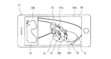
図6は、図2に示す携帯情報端末11の表示画面50の第3例を示す図面である。図6では、タイヤ力画像72A,72Bは、縦タイヤ力及び横タイヤ力の合力(ベクトル和)を車輪の路面接地点を起点としてベクトル表示、具体的には矢印75で表示している。即ち、矢印75の長さがタイヤ力の大きさを示し、矢印75の向きがタイヤ力としてタイヤに作用する力の向きを表す。なお、車輪に作用する垂直抗力をタイヤに作用する力として矢印で表示してもよい。   FIG. 6 is a drawing showing a third example of the display screen 50 of the portable information terminal 11 shown in FIG. In FIG. 6, the tire force images 72 </ b> A and 72 </ b> B show the resultant force (vector sum) of the vertical tire force and the lateral tire force in vector display starting from the road contact point of the wheel, specifically, an arrow 75. That is, the length of the arrow 75 indicates the magnitude of the tire force, and the direction of the arrow 75 indicates the direction of the force acting on the tire as the tire force. The normal force acting on the wheel may be indicated by an arrow as the force acting on the tire.

タイヤ力画像72A,72Bには、垂直抗力と摩擦係数との積である最大摩擦力が表示される。図6の例では、タイヤ力画像72A,72Bにおいて、摩擦円Cfが表示されることで最大摩擦力として摩擦限界が表示される。摩擦円Cfは、接地点を中心として最大摩擦力の大きさを半径とする円または楕円によって表わされる。このように、各タイヤ力画像72A,72Bは、タイヤ力の作用する向き及びタイヤ力の大きさを可視化する表示であれば図4に示した円形表示に限られず、図6に示す矢印表示としてもよい。その場合、矢印75の向きでタイヤ力の作用する向きを表現し、矢印75の大きさでタイヤ力の大きさを表現すればよい。また、タイヤ力の作用する向きが理解できればよい。例えば、タイヤ力の向きに起因して矢印75が車体画像51aに隠れてしまう場合には、タイヤ力が反作用として路面に与える力を矢印として表示してもよいし、矢印75の表示位置を車輪の路面接地点からずらして表示してもよい。 On the tire force images 72A and 72B, the maximum friction force, which is the product of the normal force and the friction coefficient, is displayed. In the example of FIG. 6, the tire force image 72A, the 72B, the friction circle C f is the friction force limit is displayed as a maximum friction force by being displayed. The friction circle C f is represented by a circle or an ellipse having the radius of the magnitude of the maximum friction force around the contact point. As described above, the tire force images 72A and 72B are not limited to the circular display shown in FIG. 4 as long as the direction in which the tire force acts and the size of the tire force are visualized. Is also good. In this case, the direction in which the tire force acts is represented by the direction of the arrow 75, and the magnitude of the tire force may be represented by the size of the arrow 75. Also, it is only necessary to understand the direction in which the tire force acts. For example, when the arrow 75 is hidden in the vehicle body image 51a due to the direction of the tire force, the force exerted on the road surface by the tire force as a reaction may be displayed as an arrow, or the display position of the arrow 75 may be changed to the wheel position. May be displayed shifted from the ground contact point of the road.

タイヤ力画像72A,72Bは、運転者の理解容易のために前述した余裕度FS(図3参照)に合わせて表示形態を変えてもよい。具体的には、タイヤ力画像72A,72Bは、タイヤ力を表す矢印75、摩擦円Cfの輪郭又はその内部領域、及び、矢印75と摩擦円Cfとの間の領域の少なくとも1つの色を変化させることで余裕度FSを表す。例えば、余裕度FSが大きい場合には、当該色を青色で表示し、余裕度FSが小さくなるにつれて、当該色を緑色、黄色、橙色、赤色と順番にグラデーション変化させてもよい。 The display forms of the tire force images 72A and 72B may be changed in accordance with the above-mentioned margin FS (see FIG. 3) for easy understanding of the driver. Specifically, the tire force image 72A, 72B is an arrow 75 representing the tire force, the contour or internal region thereof of the friction circle C f, and at least one color of the area between the arrows 75 and friction circle C f Is changed to represent the margin FS. For example, when the margin FS is large, the color may be displayed in blue, and as the margin FS decreases, the color may be changed in gradation in the order of green, yellow, orange, and red.

このように走行状態に応じて変化する垂直抗力を反映して摩擦円Cf、余裕度FS及びタイヤ力を合わせてタイヤ力画像72A,72Bに表示することで、スリップ可能性についてより把握しやすくなる。また、前輪及び後輪の回転数に基づいてスリップ率を判定できる場合には、タイヤ力画像72A,72Bと併せて、スリップ発生の有無又はスリップ状態レベルを表示してもよい。これにより、車輪のグリップ状態の理解を促進することができる。また、タイヤ力画像72A,72Bと併せて、走行速度及び/又は加速度を表示してもよい。これによって、走行速度や加速度の違いによる摩擦円Cfやタイヤ力の違いを理解しやすくできる。なお、スリップ率、走行速度、加速度などの情報についても、非文字の画像情報として、色、形、向きなどで表すことが好ましい。 By displaying the friction circle C f , the allowance FS, and the tire force in the tire force images 72A and 72B together with reflecting the normal force that changes according to the running state in this manner, it is easier to grasp the possibility of slip. Become. If the slip ratio can be determined based on the rotational speeds of the front wheels and the rear wheels, the presence or absence of slip or the slip state level may be displayed together with the tire force images 72A and 72B. Thereby, the understanding of the grip state of the wheel can be promoted. Further, the traveling speed and / or the acceleration may be displayed together with the tire force images 72A and 72B. This makes it easy to understand the difference in the friction circle Cf and the difference in the tire force due to the difference in the traveling speed and the acceleration. In addition, it is preferable that information such as a slip rate, a traveling speed, and an acceleration is represented by color, shape, direction, and the like as non-character image information.

また、図6に示すように、表示画面50には、走行経路とともに走行位置を示す経路情報73を表示する経路情報領域50bを動画領域50aと併せて表示してもよい。例えば、走行経路73は、車両を上空から見た場合の比較的広い範囲の経路が示される。少なくとも走行経路における曲率半径が把握可能な走行経路が表示される。経路情報73には、動画領域50aで表示される車両の走行位置を走行経路上に表示する。即ち、経路情報領域50bにおける走行位置と、動画領域50aにおける車両画像51及びタイヤ力画像72A,72Bとは、互いに同期して関連表示される。経路情報73は、ナビゲーション情報やGPS情報に基づいて生成される。このような構成により、表示画面50を見た運転者は、曲率半径が分かる走行経路情報73を認識した上で、動画表示される車両画像51およびタイヤ力72A,72Bを把握することができ、走行状態を良好に把握することができる。   Further, as shown in FIG. 6, a route information area 50b for displaying route information 73 indicating a travel position together with a travel route may be displayed on the display screen 50 together with the moving image area 50a. For example, the travel route 73 is a route in a relatively wide range when the vehicle is viewed from above. At least a traveling route on which the radius of curvature of the traveling route can be grasped is displayed. In the route information 73, the traveling position of the vehicle displayed in the moving image area 50a is displayed on the traveling route. That is, the traveling position in the route information area 50b and the vehicle image 51 and the tire force images 72A and 72B in the moving image area 50a are displayed in association with each other in synchronization with each other. The route information 73 is generated based on navigation information and GPS information. With such a configuration, the driver who sees the display screen 50 can recognize the vehicle image 51 and the tire forces 72A and 72B that are displayed as a moving image after recognizing the travel route information 73 where the radius of curvature is known. The running state can be grasped well.

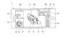
図7は、図2に示す携帯情報端末11の表示画面50の第4例を示す図面である。図7では、携帯情報端末11の表示画面50には、3つのセグメント50a〜cが表示される。第1セグメント50aは、動画領域であり、車両画像51とともにタイヤ力画像75が表示される。この例では、タイヤ力画像75は、車輪の接地点を起点としてベクトル表示、具体的には矢印で表示される。即ち、当該矢印の長さがタイヤ力の大きさを示し、当該矢印の向きがタイヤ力としてタイヤに作用する力の向きを表す。   FIG. 7 is a drawing showing a fourth example of the display screen 50 of the portable information terminal 11 shown in FIG. In FIG. 7, the display screen 50 of the portable information terminal 11 displays three segments 50a to 50c. The first segment 50a is a moving image area, and a tire force image 75 is displayed together with the vehicle image 51. In this example, the tire force image 75 is displayed as a vector starting from the ground contact point of the wheel, specifically, displayed as an arrow. That is, the length of the arrow indicates the magnitude of the tire force, and the direction of the arrow indicates the direction of the force acting on the tire as the tire force.

また、車輪の周囲には、車輪から路面に作用する鉛直荷重(或いは路面から車輪に作用する垂直抗力)の大きさを示す円82(例えば、楕円)で表示される。円82の大きさは、当該鉛直荷重の大きさに合わせて変化する。鉛直荷重は、上下方向の荷重であり、車体重量、加減速、ピッチ姿勢変化に基づいて設定される。例えば、加速走行状態では、駆動輪(後輪)には、車体重量による垂直荷重に、駆動輪から路面に与える垂直荷重成分が加えられた値が鉛直荷重として作用する。鉛直荷重の増加に伴って円82の半径が大きくなる。本実施形態では、鉛直荷重の増加に比例して円82の半径が大きくなる。他の例としては、荷重増加に比例して、円面積が大きくなるようにしてもよい。更に他の例として、荷重増加に比例して円の大きさ変化に加えて、その表示色も変化させてもよい。   A circle 82 (for example, an ellipse) indicating the magnitude of a vertical load acting on the road surface from the wheel (or a vertical drag acting on the wheel from the road surface) is displayed around the wheel. The size of the circle 82 changes according to the magnitude of the vertical load. The vertical load is a load in the vertical direction, and is set based on the vehicle body weight, acceleration / deceleration, and change in pitch attitude. For example, in an accelerated running state, a value obtained by adding a vertical load component applied to the road surface from the drive wheels to a vertical load due to the vehicle weight acts on the drive wheels (rear wheels) as a vertical load. The radius of the circle 82 increases as the vertical load increases. In the present embodiment, the radius of the circle 82 increases in proportion to the increase in the vertical load. As another example, the circular area may be increased in proportion to the load increase. As still another example, the display color may be changed in addition to the change in the size of the circle in proportion to the load increase.

前輪に生じる鉛直荷重を表す円82と、後輪にかかる鉛直荷重を表す楕円82とで、表示対応(例えば、表示色)を異ならせてもよい。これによって、前後輪にそれぞれ生じる鉛直荷重を容易に区別することができる。また本実施形態では、円82は鉛直荷重を表わしているが、想定される摩擦係数を鉛直荷重に乗算した摩擦限界値を表す円82を各車輪下に表示してもよい。   The display correspondence (for example, display color) may be different between a circle 82 representing a vertical load applied to the front wheel and an ellipse 82 representing a vertical load applied to the rear wheel. Thus, the vertical loads generated on the front and rear wheels can be easily distinguished. Further, in the present embodiment, the circle 82 represents the vertical load, but the circle 82 representing the friction limit value obtained by multiplying the assumed friction coefficient by the vertical load may be displayed below each wheel.

他の例として、車輪下の円82の表示色をグリップ限界の変化に応じて異ならせる場合には、タイヤ力画像75の表示色とタイヤ力の値との間の対応関係と、グリップ限界の円82の表示色とグリップ限界の値との間の対応関係とを一致させるとよい。そうすれば、タイヤ力画像75の表示色の色相がグリップ限界の円82の表示色の色相に近づけば、余裕度FSが少ないと把握できる一方、タイヤ力画像75の表示色の色相がグリップ限界の円82の表示色の色相から遠くなれば、余裕度FSが大きいと把握できる。例えば、タイヤ力画像75の表示色が青色で、グリップ限界の円82が黄色となる場合に比べて、タイヤ力画像75の表示色が青色で、グリップ限界の円82が赤色となる場合は、余裕度FSが大きいと判断できる。   As another example, when the display color of the circle 82 under the wheel is changed according to the change in the grip limit, the correspondence between the display color of the tire force image 75 and the value of the tire force and the grip limit The correspondence between the display color of the circle 82 and the value of the grip limit may be matched. Then, if the hue of the display color of the tire force image 75 approaches the hue of the display color of the circle 82 of the grip limit, it can be understood that the margin FS is small, while the hue of the display color of the tire force image 75 is the grip limit. If the distance from the hue of the display color of the circle 82 becomes far, it can be understood that the margin FS is large. For example, if the display color of the tire force image 75 is blue and the circle 82 of the grip limit is red, compared to the case where the display color of the tire force image 75 is blue and the circle 82 of the grip limit is yellow, It can be determined that the margin FS is large.

第2セグメント50bは、詳細データ領域であり、前輪及び後輪のタイヤ力の大きさを表す棒グラフ84が表示される。棒グラフ84の大きさがタイヤ力の大きさに対応している。なお、棒グラフ84の色は、タイヤ力の大きさに応じたグラデーションで表示されてもよい。第2セグメント50bには、走行速度85も表示される。   The second segment 50b is a detailed data area, and a bar graph 84 representing the magnitude of the tire force of the front wheel and the rear wheel is displayed. The size of the bar graph 84 corresponds to the magnitude of the tire force. Note that the color of the bar graph 84 may be displayed in a gradation corresponding to the magnitude of the tire force. The traveling speed 85 is also displayed in the second segment 50b.

また、第2セグメント50bには、運転者の操作情報も表示される。例えば、当該操作情報として加減速のための操作の情報が表示される。具体的には、当該操作情報として、アクセル操作量86及びブレーキ操作量87が表示される。図7の例では、走行速度85を表示する円の外周に沿ってアクセル操作量86及びブレーキ操作量87を長さで表現する表示領域が設けられる。それらの円弧の長さが長くなるほど、操作量が大きいことを意味する。例えば、左側にアクセル操作量が表示され、右側にブレーキ操作量が表示される。ブレーキ操作量87の表示は、前後ブレーキ操作量のいずれかであってもよいし、前後ブレーキ操作量を総合した量であってもよい。なお、前記操作情報は、クラッチ操作量、変速操作量、運転者姿勢変化などを含んでもよい。   In addition, driver operation information is also displayed in the second segment 50b. For example, operation information for acceleration / deceleration is displayed as the operation information. Specifically, an accelerator operation amount 86 and a brake operation amount 87 are displayed as the operation information. In the example of FIG. 7, a display area that represents the accelerator operation amount 86 and the brake operation amount 87 by length is provided along the outer circumference of the circle that displays the traveling speed 85. The longer the length of these arcs, the greater the amount of operation. For example, the accelerator operation amount is displayed on the left side, and the brake operation amount is displayed on the right side. The display of the brake operation amount 87 may be any of the front and rear brake operation amounts, or may be a total amount of the front and rear brake operation amounts. The operation information may include a clutch operation amount, a shift operation amount, a change in the driver's posture, and the like.

第3セグメント50cは、表示態様選択領域であり、第1セグメント50aの表示態様を選択するための入力エリア91〜93が表示される。第1入力エリア91には、車両画像51の視点(即ち、表示される車両の向き)を選ぶための選択肢が設けられている。当該選択肢は、例えば、正面視、斜視、正面視及び斜視の二画面等としているが、その他の視点も追加してもよい。第2入力エリア92には、縦タイヤ力、横タイヤ力及び垂直抗力の各々の表示の有無を選ぶための選択肢が設けられている。本実施形態では、縦タイヤ力及び横タイヤ力の両方を選択すると、タイヤ力画像75の矢印が、縦タイヤ力及び横タイヤ力の合力となる。縦タイヤ力及び横タイヤ力の片方を選択すると、タイヤ力画像75の矢印が当該片方の力となる。第3入力エリア93には、第1セグメント50aの動画再生速度の選択肢が設けられている。例えば、当該選択肢は、実速度再生、スロー再生及び早送り再生の複数段階の選択肢を有する。なお、第1セグメント50aには、現表示時点が全体計測時間(全動画時間)のうちどの時間帯であるかを示す動画再生位置表示バーが設けられてもよい。   The third segment 50c is a display mode selection area, and displays input areas 91 to 93 for selecting the display mode of the first segment 50a. In the first input area 91, options for selecting the viewpoint of the vehicle image 51 (that is, the direction of the displayed vehicle) are provided. The options are, for example, two screens of front view, perspective, front view, and perspective, but other viewpoints may be added. In the second input area 92, options for selecting whether or not to display each of the vertical tire force, the lateral tire force, and the vertical drag are provided. In the present embodiment, when both the vertical tire force and the lateral tire force are selected, the arrow of the tire force image 75 becomes the resultant force of the vertical tire force and the lateral tire force. When one of the vertical tire force and the lateral tire force is selected, the arrow of the tire force image 75 indicates the one of the forces. In the third input area 93, options for the moving image playback speed of the first segment 50a are provided. For example, the options include a multi-stage option of real speed playback, slow playback, and fast forward playback. Note that the first segment 50a may be provided with a moving image playback position display bar that indicates which time zone the current display time point is in the total measured time (all moving image time).

なお、図4乃至7に示す表示方法は一例であり、他の表示方法が用いられる場合も本発明に含まれる。また図4乃至7に記載した構成を互いに組み合わせたり、一部を省略した場合も本発明に含まれる。例えば、車両画像51に重ねて表示するタイヤ力画像52A,52Bは、前輪3及び後輪4の両方について個別に表示しなくてもよく、片方だけ(例えば、後輪タイヤ力画像52Aのみ)を表示してもよいし、両者を統合(例えば、平均化)したタイヤ力を求めて表示してもよい。背景画像51c等は省略されてもよい。   Note that the display methods shown in FIGS. 4 to 7 are examples, and the case where another display method is used is also included in the present invention. In addition, the present invention includes a case where the configurations illustrated in FIGS. 4 to 7 are combined with each other or a part of the configurations is omitted. For example, the tire force images 52A and 52B displayed on the vehicle image 51 do not have to be individually displayed for both the front wheel 3 and the rear wheel 4, and only one of them (for example, only the rear wheel force image 52A) is displayed. The information may be displayed, or the tire force obtained by integrating (for example, averaging) the both may be obtained and displayed. The background image 51c and the like may be omitted.

前記実施形態では、車両の前方斜めからの画像を表示したが、車両の正面視または背面視による車両画像を表示させてもよい。車両の正面視または背面視による画像を用いることで、車両のリーン状態を分かりやすく表示することができる。また車両の上面視による画像を用いることで、前後輪それぞれのタイヤ力を1つの画面に表示しやすくすることができる。また車両を複数の視点から見た画像を選択可能に表示してもよい。これによって、運転者の好む視点や認識しやすい視点で、車両の傾斜とタイヤ力を表示させることができ、理解度や利便性を向上させることができる。   In the above embodiment, the image is displayed obliquely from the front of the vehicle. However, a vehicle image may be displayed when the vehicle is viewed from the front or rear. By using the image of the vehicle viewed from the front or the rear, the lean state of the vehicle can be displayed in an easily understandable manner. Further, by using the image of the vehicle viewed from above, it is possible to easily display the tire forces of the front and rear wheels on one screen. Further, images of the vehicle viewed from a plurality of viewpoints may be displayed so as to be selectable. As a result, the inclination of the vehicle and the tire force can be displayed from a viewpoint preferred by the driver or a viewpoint that is easy to recognize, so that understanding and convenience can be improved.

また前記実施形態では、車両に作用する力としてタイヤ力を用いたがタイヤ力以外に車両に作用する力を表示させてもよい。たとえば遠心力、操舵軸にかかる力、運転者による体重移動力などを表示してもよい。また前記した実施形態では、縦タイヤ力および横タイヤ力の合力を表示したが、縦タイヤ力、横タイヤ力および垂直抗力の少なくとも1つを表示してもよい。好ましくは、タイヤ力に相当する力(遠心力を含む)と、垂直抗力に相当する力(摩擦円、余裕度を含む)との両方が表示されると好ましい。   Further, in the above embodiment, the tire force is used as the force acting on the vehicle, but a force acting on the vehicle other than the tire force may be displayed. For example, a centrifugal force, a force applied to a steering shaft, a weight moving force by a driver, and the like may be displayed. In the above-described embodiment, the resultant force of the vertical tire force and the lateral tire force is displayed. However, at least one of the vertical tire force, the lateral tire force, and the vertical drag may be displayed. Preferably, both a force (including a centrifugal force) corresponding to the tire force and a force (including the friction circle and the allowance) corresponding to the normal force are preferably displayed.

また、本実施形態では、携帯情報端末11に画像を表示する構成としたが、画像を表示する表示装置は、携帯情報端末に限らない。たとえば外部のサーバ12に情報を記憶することで、サーバ12に接続される種々の表示装置で画像を表示してもよい。たとえば卓上のコンピュータやノートパソコンに画像を表示させてもよい。また自動二輪車に設けられるメータ装置などの表示装置に画像を表示させてもよい。メータ装置に画像を表示させることで、自動二輪車に搭載された通信システム内で情報のやり取りを行うことができ、システム構成を簡単化することができる。   In the present embodiment, an image is displayed on the portable information terminal 11, but the display device for displaying the image is not limited to the portable information terminal. For example, by storing information in an external server 12, an image may be displayed on various display devices connected to the server 12. For example, the image may be displayed on a desktop computer or a laptop computer. Further, the image may be displayed on a display device such as a meter device provided in the motorcycle. By displaying an image on the meter device, information can be exchanged in a communication system mounted on the motorcycle, and the system configuration can be simplified.

また、本実施形態では、車両に設けられるタイヤ力演算部33がタイヤ力を演算し、演算したタイヤ力を表示する装置である情報携帯端末11に送信する構成としたがこれに限らない。具体的には、タイヤ力を演算するための情報を、携帯情報端末11または外部サーバ12に送信することで、車両に設けられる演算部以外でタイヤ力を演算してもよい。これによって走行中の車両の演算部における演算負荷を抑えることができる。また走行中には、タイヤ力を演算するために必要な情報を順次記憶し、走行終了後に記憶した情報を携帯情報端末11または外部サーバ12に送信するようにしてもよい。これによっても走行中の演算負荷を抑えることができる。また、運転者の携帯する情報携帯端末11に画像表示のための情報を送信し、情報携帯端末11に記憶させることで、通信ネットワークNへの接続が不安定なエリアでも安定して走行情報を取得することができる。また、自動二輪車以外のリーン型車両についても同様に本発明を適用することができる。   In the present embodiment, the tire force calculation unit 33 provided in the vehicle calculates the tire force and transmits the calculated tire force to the information portable terminal 11 which is a device for displaying the calculated tire force. However, the present invention is not limited to this. Specifically, by transmitting information for calculating the tire force to the portable information terminal 11 or the external server 12, the tire force may be calculated by a unit other than the calculation unit provided in the vehicle. As a result, the calculation load on the calculation unit of the running vehicle can be reduced. During traveling, information necessary for calculating the tire force may be sequentially stored, and the stored information may be transmitted to the portable information terminal 11 or the external server 12 after traveling. This can also reduce the calculation load during traveling. In addition, by transmitting information for image display to the information portable terminal 11 carried by the driver and storing the information in the information portable terminal 11, stable driving information can be obtained even in an area where connection to the communication network N is unstable. Can be obtained. Further, the present invention can be similarly applied to a lean type vehicle other than the motorcycle.

1 走行データ表示システム
2 自動二輪車(車両)
3 前輪
4 後輪
5 車体
10 走行データ管理装置
11 携帯情報端末
22 IMU(力関連値検出装置)
23 エンジン回転数センサ(力関連値検出装置)
24 車速センサ(力関連値検出装置)
25 駆動輪速度センサ(力関連値検出装置)
26 ブレーキ圧センサ(力関連値検出装置)
27 リーン角センサ(力関連値検出装置)
33 タイヤ力演算部(演算装置)
34 遠心力演算部(演算装置)
36 制御部(制御装置)
50 表示画面
51 車両画像
52A,52B タイヤ力画像(力画像)
62A,62B 参照タイヤ力画像(参照力画像)
1 Driving data display system 2 Motorcycle (vehicle)
Reference Signs List 3 front wheel 4 rear wheel 5 body 10 running data management device 11 portable information terminal 22 IMU (force-related value detection device)
23 Engine speed sensor (force-related value detection device)
24 Vehicle speed sensor (force-related value detection device)
25 Drive wheel speed sensor (force-related value detection device)
26 Brake pressure sensor (force-related value detection device)
27 Lean angle sensor (force-related value detection device)
33 Tire force calculation unit (calculation device)
34 Centrifugal force calculation unit (calculation device)
36 control unit (control device)
50 display screen 51 vehicle image 52A, 52B tire force image (force image)
62A, 62B Reference tire force image (reference force image)

Claims (10)

車両を示す車両画像を表示すると共に、前記車両に設けられる検出装置で検出された走行データに基づいて求められる走行中に前記車両に作用した力を示す力画像を前記車両画像と一緒に表示する、走行データ表示方法。   A vehicle image indicating the vehicle is displayed, and a force image indicating a force applied to the vehicle during traveling determined based on traveling data detected by a detection device provided in the vehicle is displayed together with the vehicle image. , Driving data display method. 前記力画像は、前記力の作用する向き及び前記力の大きさを可視化する表示を有する、請求項1に記載の走行データ表示方法。   The travel data display method according to claim 1, wherein the force image has a display for visualizing a direction in which the force acts and a magnitude of the force. 前記力画像は、前記車両の車輪に路面から作用する力の情報を含む、請求項1又は2に記載の走行データ表示方法。   The driving data display method according to claim 1, wherein the force image includes information on a force acting on a wheel of the vehicle from a road surface. 前記力画像は、前記車両の前輪タイヤに作用する前輪タイヤ力を示す前輪タイヤ力画像と、前記車両の後輪タイヤに作用する後輪タイヤ力を示す後輪タイヤ力画像とを含む、請求項3に記載の走行データ表示方法。   The force image includes a front wheel force image indicating a front wheel force acting on a front wheel tire of the vehicle, and a rear wheel force image indicating a rear wheel force acting on a rear wheel tire of the vehicle. 3. The driving data display method according to 3. 前記力画像を走行状態の時間変化に応じて表示変化させる、請求項1乃至4のいずれか1項に記載の走行データ表示方法。   The running data display method according to any one of claims 1 to 4, wherein the display of the force image is changed according to a time change of a running state. 前記車両は、車体を左右方向に傾斜させて旋回するリーン車両であって、
前記車両画像は、前記車両の旋回時における前記車体のリーン姿勢を反映させて表示される、請求項1乃至5のいずれか1項に記載の走行データ表示方法。
The vehicle is a lean vehicle that turns while leaning the vehicle body in the left-right direction,
The travel data display method according to claim 1, wherein the vehicle image is displayed by reflecting a lean posture of the vehicle body when the vehicle turns.
前記検出装置の検出結果とは別に生成されて前記車両に作用した前記力と比較するための力の参照値を示す参照力画像を前記力画像と共に更に表示する、請求項1乃至6のいずれか1項に記載の走行データ表示方法。   The reference force image, which is generated separately from a detection result of the detection device and indicates a reference value of a force to be compared with the force applied to the vehicle, is further displayed together with the force image. The driving data display method according to claim 1. 前記車両に作用した前記力の実際値を補正して得られる補正値に基づいて前記力画像を生成する、請求項1乃至7のいずれか1項に記載の走行データ表示方法。   The driving data display method according to any one of claims 1 to 7, wherein the force image is generated based on a correction value obtained by correcting an actual value of the force acting on the vehicle. 車両を示す車両画像を表示装置に表示させると共に、前記車両に作用した力を示す力画像を前記車両画像と一緒に前記表示装置に表示させる、走行データ表示プログラム。   A traveling data display program that causes a display device to display a vehicle image indicating a vehicle, and causes the display device to display a force image indicating a force applied to the vehicle together with the vehicle image. 車両に作用する力に関連する力関連値を検出する力関連値検出装置と、
前記検出装置の検出結果に基づいて前記力を演算する演算装置と、
前記車両のリーン姿勢を検出するリーン姿勢検出装置と、
走行中の予め定める間隔ごとに前記力及び前記リーン姿勢をそれぞれ記憶する記憶装置と、
前記記憶装置から記憶情報を読み出し、前記車両を示す車両画像を表示装置に表示させると共に、前記車両に作用した前記力を示す力画像を前記車両画像と一緒に前記表示装置に表示させる制御装置と、を備える、走行データ表示システム。
A force-related value detection device that detects a force-related value related to a force acting on the vehicle,
A calculating device that calculates the force based on a detection result of the detecting device,
A lean attitude detection device that detects a lean attitude of the vehicle,
A storage device that stores the force and the lean posture at predetermined intervals during traveling,
A control device that reads stored information from the storage device, causes a display device to display a vehicle image indicating the vehicle, and displays a force image indicating the force applied to the vehicle on the display device together with the vehicle image. A driving data display system comprising:
JP2018184199A 2018-09-28 2018-09-28 Running data display method, program and system Active JP7245019B2 (en)

Priority Applications (1)

Application Number Priority Date Filing Date Title
JP2018184199A JP7245019B2 (en) 2018-09-28 2018-09-28 Running data display method, program and system

Applications Claiming Priority (1)

Application Number Priority Date Filing Date Title
JP2018184199A JP7245019B2 (en) 2018-09-28 2018-09-28 Running data display method, program and system

Publications (2)

Publication Number Publication Date
JP2020052932A true JP2020052932A (en) 2020-04-02
JP7245019B2 JP7245019B2 (en) 2023-03-23

Family

ID=69997408

Family Applications (1)

Application Number Title Priority Date Filing Date
JP2018184199A Active JP7245019B2 (en) 2018-09-28 2018-09-28 Running data display method, program and system

Country Status (1)

Country Link
JP (1) JP7245019B2 (en)

Cited By (5)

* Cited by examiner, † Cited by third party
Publication number Priority date Publication date Assignee Title
WO2021193453A1 (en) 2020-03-24 2021-09-30 横河電機株式会社 Methane generating device
JP2021168056A (en) * 2020-04-13 2021-10-21 川崎重工業株式会社 Vehicle-related output programs, systems and methods
JP6980138B1 (en) * 2020-07-20 2021-12-15 三菱電機株式会社 Display control device and display control method
JP2022157538A (en) * 2021-03-31 2022-10-14 本田技研工業株式会社 Driving evaluation device, driving evaluation method, program, and medium
JP2022157611A (en) * 2021-03-31 2022-10-14 本田技研工業株式会社 Driving evaluation device, driving evaluation method, program, and medium

Citations (8)

* Cited by examiner, † Cited by third party
Publication number Priority date Publication date Assignee Title
JP2002048581A (en) * 2000-08-01 2002-02-15 Alpine Electronics Inc Navigation device
JP2009023655A (en) * 2003-10-20 2009-02-05 Yamaha Motor Co Ltd Driving information display method and driving information display system for motorcycles
JP2011166371A (en) * 2010-02-08 2011-08-25 Victor Co Of Japan Ltd Imaging apparatus and imaging method
JP2012133023A (en) * 2010-12-20 2012-07-12 Dig Spice Co Ltd Vehicle travel reproduction evaluation device
WO2013099246A1 (en) * 2011-12-26 2013-07-04 ヤマハ発動機株式会社 Driving skill information presentation device
JP2015085905A (en) * 2013-11-01 2015-05-07 ヤマハ発動機株式会社 Saddle-type vehicle and wheel force acquisition device
US20150172517A1 (en) * 2013-12-16 2015-06-18 Innova Electronics, Inc. Flexible camera device
JP2016219864A (en) * 2015-05-14 2016-12-22 日立建機株式会社 Work vehicle ambient monitoring device

Patent Citations (8)

* Cited by examiner, † Cited by third party
Publication number Priority date Publication date Assignee Title
JP2002048581A (en) * 2000-08-01 2002-02-15 Alpine Electronics Inc Navigation device
JP2009023655A (en) * 2003-10-20 2009-02-05 Yamaha Motor Co Ltd Driving information display method and driving information display system for motorcycles
JP2011166371A (en) * 2010-02-08 2011-08-25 Victor Co Of Japan Ltd Imaging apparatus and imaging method
JP2012133023A (en) * 2010-12-20 2012-07-12 Dig Spice Co Ltd Vehicle travel reproduction evaluation device
WO2013099246A1 (en) * 2011-12-26 2013-07-04 ヤマハ発動機株式会社 Driving skill information presentation device
JP2015085905A (en) * 2013-11-01 2015-05-07 ヤマハ発動機株式会社 Saddle-type vehicle and wheel force acquisition device
US20150172517A1 (en) * 2013-12-16 2015-06-18 Innova Electronics, Inc. Flexible camera device
JP2016219864A (en) * 2015-05-14 2016-12-22 日立建機株式会社 Work vehicle ambient monitoring device

Cited By (12)

* Cited by examiner, † Cited by third party
Publication number Priority date Publication date Assignee Title
WO2021193453A1 (en) 2020-03-24 2021-09-30 横河電機株式会社 Methane generating device
JP2021168056A (en) * 2020-04-13 2021-10-21 川崎重工業株式会社 Vehicle-related output programs, systems and methods
JP7422599B2 (en) 2020-04-13 2024-01-26 カワサキモータース株式会社 Vehicle related output programs, systems and methods
JP6980138B1 (en) * 2020-07-20 2021-12-15 三菱電機株式会社 Display control device and display control method
US12187126B2 (en) 2020-07-20 2025-01-07 Mitsubishi Electric Corporation Display control device and display control method
JP2022157538A (en) * 2021-03-31 2022-10-14 本田技研工業株式会社 Driving evaluation device, driving evaluation method, program, and medium
JP2022157611A (en) * 2021-03-31 2022-10-14 本田技研工業株式会社 Driving evaluation device, driving evaluation method, program, and medium
CN115214689A (en) * 2021-03-31 2022-10-21 本田技研工业株式会社 Driving evaluation device, driving evaluation method, program, and medium
JP7291742B2 (en) 2021-03-31 2023-06-15 本田技研工業株式会社 Driving evaluation device, driving evaluation method, program, and medium
JP7291743B2 (en) 2021-03-31 2023-06-15 本田技研工業株式会社 Driving evaluation device, driving evaluation method, program, and medium
US11928901B2 (en) 2021-03-31 2024-03-12 Honda Motor Co., Ltd Driving evaluation device and driving evaluation method
CN115214689B (en) * 2021-03-31 2026-03-10 本田技研工业株式会社 Driving evaluation device, driving evaluation method, program, and medium

Also Published As

Publication number Publication date
JP7245019B2 (en) 2023-03-23

Similar Documents

Publication Publication Date Title
JP7015161B2 (en) Driving information storage method, driving information processing program and driving information storage device for lean vehicles
JP7245019B2 (en) Running data display method, program and system
CN110414831B (en) Risk assessment method and device for human-vehicle-road coupling based on driver&#39;s cognitive perspective
US20190210591A1 (en) System and Method to Enhance the Driving Performance of a Leanable Vehicle
EP2930047B1 (en) Vehicle and wheel force acquisition device
CN114906124A (en) Method and system for determining and dynamically updating routes and driving styles for passenger comfort
US20160084661A1 (en) Performance driving system and method
EP3879332A1 (en) Method for the performance-enhancing driver assistance of a road vehicle with an augmented reality interface
JPH0581449B2 (en)
US7630796B2 (en) Body action information system
JP2016134173A (en) Motorcycle driver information system
US20050049774A1 (en) Road surface frictional coefficient estimating apparatus
US20250342733A1 (en) Driving assistance apparatus, recording medium having driving assistance program recorded thereon, and driving assistance method
WO2021079494A1 (en) Leaning vehicle travel state data output device and leaning vehicle maneuvering skill determination device
JPWO2019004312A1 (en) Driving evaluation method and pseudo emotion generation method
CN114646322A (en) System and method for updating a navigation map
JP2018179543A (en) Estimation apparatus and estimation method
US11904878B2 (en) System and method for off-road driving assistance for a vehicle
US11669936B2 (en) Vehicle-related output program, system, and method
CN113423636A (en) System for improving performance of cyclists on bicycles
EP3945286B1 (en) Travel route generation system, travel route generation program, and travel route generation method
JP7403369B2 (en) Information provision device, information provision method, and program
JP6853878B2 (en) Vehicle pseudo-emotion generation system and conversation information output method
JP2006349003A (en) Vehicle control apparatus and vehicle control method
CN115431972A (en) System and method for controlling driving speed of a vehicle

Legal Events

Date Code Title Description
A621 Written request for application examination

Free format text: JAPANESE INTERMEDIATE CODE: A621

Effective date: 20210420

A711 Notification of change in applicant

Free format text: JAPANESE INTERMEDIATE CODE: A712

Effective date: 20211029

A977 Report on retrieval

Free format text: JAPANESE INTERMEDIATE CODE: A971007

Effective date: 20220329

A131 Notification of reasons for refusal

Free format text: JAPANESE INTERMEDIATE CODE: A131

Effective date: 20220405

A521 Request for written amendment filed

Free format text: JAPANESE INTERMEDIATE CODE: A523

Effective date: 20220427

A02 Decision of refusal

Free format text: JAPANESE INTERMEDIATE CODE: A02

Effective date: 20220920

A521 Request for written amendment filed

Free format text: JAPANESE INTERMEDIATE CODE: A523

Effective date: 20221216

C60 Trial request (containing other claim documents, opposition documents)

Free format text: JAPANESE INTERMEDIATE CODE: C60

Effective date: 20221216

A911 Transfer to examiner for re-examination before appeal (zenchi)

Free format text: JAPANESE INTERMEDIATE CODE: A911

Effective date: 20221226

C21 Notice of transfer of a case for reconsideration by examiners before appeal proceedings

Free format text: JAPANESE INTERMEDIATE CODE: C21

Effective date: 20221227

TRDD Decision of grant or rejection written
A01 Written decision to grant a patent or to grant a registration (utility model)

Free format text: JAPANESE INTERMEDIATE CODE: A01

Effective date: 20230214

A61 First payment of annual fees (during grant procedure)

Free format text: JAPANESE INTERMEDIATE CODE: A61

Effective date: 20230310

R150 Certificate of patent or registration of utility model

Ref document number: 7245019

Country of ref document: JP

Free format text: JAPANESE INTERMEDIATE CODE: R150

R250 Receipt of annual fees

Free format text: JAPANESE INTERMEDIATE CODE: R250