JP2020051663A - Gas stove - Google Patents
Gas stove Download PDFInfo
- Publication number
- JP2020051663A JP2020051663A JP2018179958A JP2018179958A JP2020051663A JP 2020051663 A JP2020051663 A JP 2020051663A JP 2018179958 A JP2018179958 A JP 2018179958A JP 2018179958 A JP2018179958 A JP 2018179958A JP 2020051663 A JP2020051663 A JP 2020051663A
- Authority
- JP
- Japan
- Prior art keywords
- light source
- unit
- gas stove
- panel
- panel portion
- Prior art date
- Legal status (The legal status is an assumption and is not a legal conclusion. Google has not performed a legal analysis and makes no representation as to the accuracy of the status listed.)
- Granted
Links
- 238000005286 illumination Methods 0.000 claims abstract description 22
- 238000001514 detection method Methods 0.000 claims description 34
- 230000005540 biological transmission Effects 0.000 claims description 17
- 230000008859 change Effects 0.000 abstract description 2
- 238000010411 cooking Methods 0.000 description 5
- 238000010438 heat treatment Methods 0.000 description 5
- 230000006870 function Effects 0.000 description 4
- 238000006073 displacement reaction Methods 0.000 description 3
- 230000001771 impaired effect Effects 0.000 description 3
- 239000011347 resin Substances 0.000 description 3
- 229920005989 resin Polymers 0.000 description 3
- 238000010586 diagram Methods 0.000 description 2
- 230000000694 effects Effects 0.000 description 2
- 238000009434 installation Methods 0.000 description 2
- 230000009471 action Effects 0.000 description 1
- 230000008901 benefit Effects 0.000 description 1
- 230000010354 integration Effects 0.000 description 1
- 239000000463 material Substances 0.000 description 1
- 239000002184 metal Substances 0.000 description 1
- 239000007769 metal material Substances 0.000 description 1
- 230000002093 peripheral effect Effects 0.000 description 1
- 230000004044 response Effects 0.000 description 1
- XLYOFNOQVPJJNP-UHFFFAOYSA-N water Substances O XLYOFNOQVPJJNP-UHFFFAOYSA-N 0.000 description 1
Images
Classifications
-
- Y—GENERAL TAGGING OF NEW TECHNOLOGICAL DEVELOPMENTS; GENERAL TAGGING OF CROSS-SECTIONAL TECHNOLOGIES SPANNING OVER SEVERAL SECTIONS OF THE IPC; TECHNICAL SUBJECTS COVERED BY FORMER USPC CROSS-REFERENCE ART COLLECTIONS [XRACs] AND DIGESTS
- Y02—TECHNOLOGIES OR APPLICATIONS FOR MITIGATION OR ADAPTATION AGAINST CLIMATE CHANGE
- Y02B—CLIMATE CHANGE MITIGATION TECHNOLOGIES RELATED TO BUILDINGS, e.g. HOUSING, HOUSE APPLIANCES OR RELATED END-USER APPLICATIONS
- Y02B40/00—Technologies aiming at improving the efficiency of home appliances, e.g. induction cooking or efficient technologies for refrigerators, freezers or dish washers
Landscapes
- Baking, Grill, Roasting (AREA)
Abstract
Description
本発明は、ガスコンロに関するものである。 The present invention relates to a gas stove.
特許文献1のガスコンロは、コンロ本体の前側面におけるグリルの右側の下方箇所にコンロバーナ用設定操作部が開閉自在に設けられている。コンロバーナ用設定操作部の上面部には、標準火力バーナ、小火力バーナ及び大火力バーナの夫々に対する設定を行うコンロ用操作パネルが設けられている。コンロ用操作パネルが有する左コンロ操作部は、高温炒めスイッチ、湯沸しスイッチ、温度キープスイッチ、タイマースイッチ、取消スイッチ等を備えている。
In the gas stove disclosed in
特許文献1のようなガスコンロは、ユーザがコンロ用操作パネルを目視で確認しつつ、適切な操作(所定のボタンの押下)を行うことで、機器に所望の動作を行わせる。しかしながら、ガスコンロの設置場所や使用状況によっては、十分な光が得られず操作パネル付近が暗くなってしまい、操作を行い難くなるという問題が生じてしまう。
In the gas stove disclosed in
このような問題に対して、例えば、操作パネル付近を照らすような専用の照明器具を、ガスコンロの設置場所付近に設けるという対策が考えられる。しかしながら、このようにガスコンロの周辺に専用の照明器具を別途設けると、ガスコンロの周辺が煩雑になってしまい、ガスコンロを用いた調理の妨げになる虞がある。 In order to solve such a problem, for example, a countermeasure to provide a dedicated lighting device for illuminating the vicinity of the operation panel near the installation location of the gas stove is considered. However, if a dedicated lighting fixture is separately provided around the gas stove in this way, the periphery of the gas stove becomes complicated, which may hinder cooking using the gas stove.
本発明は、上述した課題の少なくとも1つを解決するためになされたものであり、突出状態及び収納状態に変化し得る操作パネル部を備えたガスコンロにおいて、操作パネル部の操作面が露出した状態にあるときに操作面を明るく照らすことができる構成を、より簡易に実現することを目的とするものである。 SUMMARY An advantage of some aspects of the invention is to provide a gas stove having an operation panel portion that can change to a protruding state and a stored state, with an operation surface of the operation panel portion being exposed. It is an object of the present invention to more easily realize a configuration in which the operation surface can be brightly illuminated when the operation is performed.
本発明の一つであるガスコンロは、ガスバーナと、前記ガスバーナを収容する筐体部と、を備えたガスコンロであって、前記筐体部に固定され、前記ガスコンロの前面部の一部をなす上パネル部と、前記上パネル部の下側に設けられ、所定の第1位置と、前記第1位置のときよりも少なくとも一部が前方側に位置する第2位置と、の間で変位する下パネル部と、所定の操作面を有するとともに前記下パネル部と一体的に変位する構成をなし、前記下パネル部が前記第2位置にあるときに少なくとも一部が前記上パネル部よりも前側に突出し且つ前記操作面が上側を向くように配置される突出位置となり、前記下パネル部が前記第1位置のときに前記突出位置のときよりも後方側に退避した収納位置となる操作パネル部と、前記上パネル部の前面よりも後方側に設けられる光源と、を備え、前記操作パネル部が前記突出位置にある状態で前記光源から照明光が照射されたときに、前記光源からの照明光の少なくとも一部が前記操作面に照射される。 A gas stove according to one aspect of the present invention is a gas stove including a gas burner and a housing that houses the gas burner, the gas stove being fixed to the housing and forming a part of a front surface of the gas stove. A lower portion that is provided below the upper panel portion and that is displaced between a predetermined first position and a second position at least a part of which is located on the front side at the time of the first position. A panel portion, having a predetermined operation surface and configured to be integrally displaced with the lower panel portion, at least a part of the lower panel portion is located closer to the front side than the upper panel portion when the lower panel portion is at the second position. An operation panel portion that projects and is located at a projecting position where the operation surface is oriented upward, and is a storage position where the lower panel portion is in the first position and retracted rearward from the projecting position when in the first position. In front of the upper panel A light source provided on the rear side of the operation panel, and when illumination light is emitted from the light source in a state where the operation panel portion is at the protruding position, at least a part of the illumination light from the light source performs the operation. Irradiated on the surface.
本発明の一つである上記ガスコンロは、上パネル部の前面よりも後方側に光源が設けられ、操作パネル部が突出位置にある状態で光源から照明光が照射されたときに、光源からの照明光の少なくとも一部が操作面に照射される構成となっている。この構成により、ガスコンロ外に特別な専用照明を設けなくても、上パネル部の後方側に組み込まれた光源からの光を利用して操作面を明るく照らし得る。よって、突出状態及び収納状態に変化し得る操作パネル部を備えたガスコンロにおいて、操作面が露出した状態にあるときに操作面を明るく照らすことができる構成を、ガスコンロ外の特別な専用装置を用いずにより簡易に実現することができる。 The gas stove, which is one aspect of the present invention, is provided with a light source behind the front surface of the upper panel portion, and when illumination light is emitted from the light source in a state where the operation panel portion is in the protruding position, the light from the light source is At least a part of the illumination light is applied to the operation surface. With this configuration, it is possible to illuminate the operation surface brightly using light from a light source incorporated on the rear side of the upper panel unit without providing a special dedicated illumination outside the gas stove. Therefore, in a gas stove provided with an operation panel portion that can be changed to a protruding state and a stowed state, a configuration that can illuminate the operation surface brightly when the operation surface is in an exposed state uses a special dedicated device outside the gas stove. Can be realized more simply.
本発明の好ましい形態を以下に例示する。但し、本発明は以下の例に限定されない。
本発明の一つであるガスコンロは、光源の前側且つ下側に配置されるとともに光源から照射される照明光を前方側に透過させる透過部を備えていてもよい。そして、透過部は、上パネル部における下端側の一部として、又は上パネル部と下パネル部との間に配置された構成で設けられていてもよい。このようにすれば、上パネル部における下端側の一部又は上パネル部と下パネル部との間のスペースを利用して透過部を配置し、光源から操作面へと光を導出するための経路を確実に確保することができる。
この場合、透過部の前面と上パネル部の前面とが面一状に配置されていてもよい。このようにすれば、透過部と上パネル部との一体性を高めることができ、透過部を設けることによって美観が損なわれることを防ぐことができる。
Preferred embodiments of the present invention are exemplified below. However, the present invention is not limited to the following example.
The gas stove according to one aspect of the present invention may be provided with a transmission unit that is disposed in front of and below the light source and that transmits illumination light emitted from the light source to the front side. The transmission section may be provided as a part of the lower panel side of the upper panel section or in a configuration disposed between the upper panel section and the lower panel section. With this configuration, the transmission unit is disposed by utilizing a part of the lower panel side of the upper panel unit or a space between the upper panel unit and the lower panel unit, and is used to guide light from the light source to the operation surface. A route can be ensured.
In this case, the front surface of the transmission unit and the front surface of the upper panel unit may be arranged flush. With this configuration, the integrity of the transmission portion and the upper panel portion can be enhanced, and the provision of the transmission portion can prevent the appearance from being impaired.
本発明の一つであるガスコンロは、操作パネル部が収納位置又は突出位置のいずれの位置であるかを検知する検知部と、検知部の検知結果に基づき、操作パネル部が収納位置にある場合に光源を非照射状態とし、操作パネル部が突出位置にある場合に光源を照射状態にする制御を行う制御部と、を備えていてもよい。このようにすれば、ユーザは「操作パネル部を突出位置に変位させる」という簡単な操作を行うだけで光源を照射状態に切り替えることができ、操作パネル部を突出位置に変位させる操作とは別で複雑な専用操作を行わずとも操作面に照明光を照射することが可能となる。 A gas stove according to one embodiment of the present invention includes a detection unit that detects whether the operation panel unit is in a storage position or a projecting position, and a case in which the operation panel unit is in the storage position based on a detection result of the detection unit. And a control unit that controls the light source to be in the irradiation state when the operation panel unit is at the protruding position. With this configuration, the user can switch the light source to the irradiation state only by performing a simple operation of “displacing the operation panel unit to the protruding position”, which is different from the operation of displacing the operation panel unit to the protruding position. Thus, it is possible to irradiate the operation surface with illumination light without performing a complicated dedicated operation.
<実施例1>
以下、実施例1について、図面を参照して説明する。
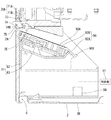
1.ガスコンロ1の概要
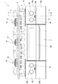
まず、ガスコンロ1について説明する。図1のように、ガスコンロ1は、調理鍋等の調理器具を加熱可能なビルトインコンロとして構成されている。ガスコンロ1は、コンロ本体部1Aによって外殻(ケース体)が構成されており、このコンロ本体部1Aの内部にガスバーナなどの各種部品が収容された構成をなす。コンロ本体部1Aは、箱状の筐体部2と、筐体部2の上端部に固定される天板3と、筐体部2の前面部2Aに固定される上パネル部70A,70Bおよび下パネル部80A,80Bとを備えている。以下の説明では、ガスコンロ1において、天板3の板厚方向を上下方向とし、上パネル部70A,70Bの板厚方向を前後方向とし、上下方向および前後方向に直交する方向を左右方向として説明する。図1では、左右方向がガスコンロ1の左右方向であり、上下方向がガスコンロ1の上下方向である。また、図4〜7では、左右方向がガスコンロ1の前後方向であり、上下方向がガスコンロ1の上下方向である。
<Example 1>
Hereinafter, a first embodiment will be described with reference to the drawings.
1. Outline of
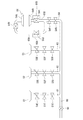
ガスコンロ1は、コンロ本体部1Aの上面を構成する天板3(トッププレート)から露出するように、右コンロ部4A、左コンロ部4B、後コンロ部4Cがそれぞれ設けられている。天板3の下方においてコンロ本体部1Aの内部中央付近にはグリル5が設けられ、グリル扉5Bによって開閉可能とされている。右コンロ部4A、左コンロ部4B、後コンロ部4C、グリル5には、図2で示すガスバーナ51,52,53,54が設けられ、ガスバーナ51,52,53,54には、分岐供給路61,62,63,64がそれぞれ接続され、これら分岐供給路61,62,63,64は、共通供給路60から分岐する。共通供給路60には、共通供給路60を開閉する元電磁弁N1が設けられ、各分岐供給路61,62,63には、各分岐供給路61,62,63を開閉可能な電磁弁(安全弁)51G,52G,53G、閉止弁51F,52F,53F、火力調整弁51E,52E,53Eがそれぞれ設けられている。安全弁51G、閉止弁51F、火力調整弁51Eは、ステッピングモータM1によって駆動され、安全弁52G、閉止弁52F、火力調整弁52Eは、ステッピングモータM2によって駆動され、安全弁53G、閉止弁53F、火力調整弁53Eは、ステッピングモータM3によって駆動される。グリル5のガスバーナ54(グリルバーナ)は、グリル5内において上側に配置される上バーナ54Aと、下側に配置される下バーナ54Bとを備え、共通供給路60から分岐してガスバーナ54にガスを導く分岐供給路64からは、上バーナ54Aにガスを導く第1供給路65Aと、下バーナ54Bにガスを導く第2供給路65Bとが分岐し、電磁弁54G、閉止弁54F、電磁弁54H,54J,54Kによってガス供給が制御される。
The
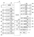
右コンロ部4A、左コンロ部4B、後コンロ部4C、グリル5のそれぞれに対応して、それぞれの点火、消火、火力調整を行うための4つの回転操作部6A,6B,6C,6Dと、各回転操作部に対応するスイッチ30A,30B,30C,30Dと、各スイッチに対応する点火信号入力回路40A,40B,40C,40Dと、各回転操作部に対応する変位検出部32A,32B,32C,32Dと、各変位検出部に対応する火力信号入力回路42A,42B,42C,42Dとがそれぞれ設けられている。更に、各ガスバーナ51,52,53,54のそれぞれに隣接してイグナイタ26A,26B,26C,26D(図3参照)が設けられ、各イグナイタに対応してイグナイタ回路46A,46B,46C,46Dがそれぞれ設けられている。制御回路10は、例えばマイクロコンピュータとして構成され、CPU10A、ROM10B、RAM10Cなどを備える。制御回路10は、上述した各電磁弁、イグナイタ26A,26B,26C,26D、モータM1,M2,M3,M4、不揮発性メモリ16などを制御し得る。操作部18は、操作ボタンやタッチパネルなどの公知の入力インタフェースによって構成される。電源回路48は電池ボックスに収容された電池49(例えば2つの乾電池)からの電力供給を受け、所定の電源電圧を生成する。
Four
2.特徴構成
次に、特徴構成について説明する。
ガスコンロ1は筐体部2を備えており、この筐体部2は、上方側が開放した箱状に構成されている。筐体部2は、ガスコンロ1の外壁をなす外壁部と、この外壁部に固定された板部やフレーム部などによって構成されている。筐体部2は、左右に一対の側壁部(図示略)を備えるとともに、これら側壁部の後端部に連結される形で後壁部(図示略)が設けられている。また、筐体部2の前面部2Aは金属部材や樹脂部材によってフレーム状又は壁状に構成されており、これら前面部、側壁部、後壁部によって筐体部2の内部空間の前後左右を囲む構成をなし、これら前面部、側壁部、後壁部の下部には底壁部2Bが連結されている。
2. Feature Configuration Next, the feature configuration will be described.
The
次に、各パネル部70A,70B,80A,80Bについて説明する。ここでは、上パネル部70Aおよび下パネル部80Aについて説明し、上パネル部70Bおよび下パネル部80Bは、それぞれ上パネル部70Aおよび下パネル部80Aと同様の構成であるため、説明を省略する。
Next, the
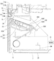
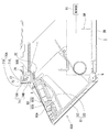
上パネル部70Aは、筐体部2に固定され、ガスコンロ1の前面部の一部をなすパネル体である。図4、図5に示すように、上パネル部70Aは、筐体部2の前面部2Aの上端側に取り付けられている。上パネル部70Aは、図1に示すように、回転操作部6A,6Dを板厚方向に貫通させるための2つの孔部を有しており、これらの孔部を介して回転操作部6A,6Dを前方に露出させている。上パネル部70Aの下端部の中央側部分は、透過部74によって構成されている。図4のように、上パネル部70Aは、樹脂材料などによって構成されるパネル本体71Aと金属材料などによって構成される装飾板71Bとを備える。図4のように、上パネル部70Aの下端部付近には、装飾板71Bとパネル本体71Aとによって内縁部が構成される孔部75が形成され、この孔部75に嵌め込まれる形で透過部74の一部(下板部74B)が配置されている。
The
下パネル部80Aは、図4、図5に示すように、上パネル部70Aの下側に設けられたパネル体であり、所定の第1位置(図4、図5)と、第1位置のときよりも少なくとも一部が前方側に位置する第2位置(図6、図7)と、の間で変位し得る。下パネル部80Aは、パネル本体と装飾板とによって板状に構成されている。下パネル部80Aは、後述するフレーム81に固定されており、フレーム81と共に一体的に変位し得る。
The
フレーム81は、下パネル部80Aを支持する支持壁部82と支持壁部82から延びるとともに操作パネル部90を支持する延設部83とを備える。支持壁部82の上端部及び延設部83の端部付近に操作パネル部90が固定されている。支持壁部82は、下パネル部が第1位置にあるときに下パネル部の後方側に立ち上がる状態で配置される板状の壁部であり、下パネル部が第2位置にあるときには前側に傾倒する構成をなす。下パネル部80Aは、後面が支持壁部82の前面に密着した状態で支持壁部82の前側に固定されている。
The
操作パネル部90は、使用者が各種操作を行うためのパネル体であり、所定の操作面90Aを有するパネル体である。操作パネル部90は、下パネル部80A及びフレーム81と一体に構成され、下パネル部80A及びフレーム81と一体的に変位(回転)する構成をなす。操作パネル部90は、バーナを用いた調理機能やタイマ調理機能などを実行するための操作などに使用されるパネルであり、操作面90Aに図3で示す操作部18(複数の押圧ボタンなど)が設けられ、ユーザが操作部18を操作することによって、各種機能の設定を行い得るようになっている。操作パネル部90は、パネル本体92Aと装飾カバー92Bとを備え、フレーム81に取り付けられている。パネル本体92Aには、操作部18を構成する要素(複数の押圧ボタンなど)が組み込まれており、複数の押圧ボタンは、装飾カバー92Bの裏面に接触した状態又は装飾カバー92Bの外側に露出した状態で配置されている。本構成では、装飾カバー92Bの表面や押圧ボタンの表面によって操作パネル部90の表面(操作面90A)が構成されている。
The
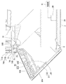
このように下パネル部80Aと操作パネル部90とフレームとが一体的に連結された構成で操作ユニットが構成されており、この操作ユニットは、下パネル部80Aの下端部付近に定められた回転軸Gを中心に回転自在に設けられている。操作ユニットが回転軸Gを中心に回転することで、下パネル部80Aは、図4、図5に示す起立した状態となる第1位置と、図6、図7に示す傾倒した状態となる第2位置と、の間で変位する。下パネル部80Aは、図6、図7に示すように、第2位置では、第1位置に位置するときよりも上端部側が前方側に位置している。なお、下パネル部80Aは、図示は省略するが、第1位置にあるときに、筐体部2の前面部2Aに係脱可能になっており、筐体部2の前面部2Aに係止することによって第1位置で位置が固定される。操作パネル部90は、操作パネル部90の前端部は、支持壁部82の上端部に隣接している。操作パネル部90の後端部は、後上方に向かうように突出する第2突部90Bが形成されている。
As described above, the operation unit is configured by integrally connecting the
操作パネル部90は、図6、図7に示すように、下パネル部80Aが第2位置にあるときに少なくとも一部(具体的には、第2突部90Bとその近傍を除いたほぼ全体)が上パネル部よりも前側に突出し且つ操作面90Aが上側を向くように配置される突出位置となり、図4、図5に示すように、下パネル部80Aが第1位置のときに突出位置のときよりも後方側に退避した収納位置となる。操作パネル部90が突出位置にあるときには、操作面90Aが上側を向き、前方に向かうにつれて低位置となるように傾斜する。また、操作パネル部90の第2突部90Bが、筐体部2の第1突部2Eに後方から当接することで、操作パネル部90の突出位置より前方への変位が規制される。これにより、下パネル部80Aは、第2位置よりも前方に回転することが規制される。
As shown in FIGS. 6 and 7, the
光源72は、例えばLEDであり、図4、図5に示すように、上パネル部70Aの前面(装飾板71Bの前面)よりも後方側に設けられている。回路基板73は、光源72が実装される基板であり、光源72を前方側の所定方向に向けるように所定の姿勢で固定されている。これにより、光源72は、上パネル部70Aの後方側に設けられている。また、回路基板73は、前方に向かうにつれて高位置となるように傾斜し、光源72が実装される基板面が前側且つ下側を向くように斜め下向きで配置される。光源72は、左右方向におけるサイズが孔部75よりも小さい。光源72は、孔部75における左右方向の中央部分の後方に位置している。光源72は、前側且つ下側に向かって照明光を照射するように配置されている。具体的には、光源72は、孔部75を後上方から前下方に向かって貫通するように、照明光(図6の矢印L参照)を照射する配置になっている。
The
透過部74は、光源72からの照射光を透過させる部材であり、例えば光透過性の樹脂によって、板状に形成されている。透過部74は、図4、図5に示すように、上パネル部70Aの下端側の一部に設けられている。具体的には、透過部74は、平板状の上板部74Aと、平板状の下板部74Bと、によって構成され、側面視で略クランク状になっている。上板部74Aは、図4に示すように、上パネル部70Aの後面に接している。下板部74Bは、孔部75内に位置している。また、透過部74は、前面(下板部74Bの前面)が上パネル部70Aの前面に対して面一状に配置されている。これにより、透過部74は、上パネル部70Aとの一体性を得ることができ、上パネル部70Aの下端側に設けられることによって美観が損なわれることを防ぐことができる。
The
検知スイッチSWは、検知部の一例に相当し、操作パネル部90の位置を検知する機能を有する。検知スイッチSWは、スイッチやセンサによって構成されており、例えば、操作パネル部90が収納位置にあるときには、制御部91に接続された所定の信号線に第1信号(非検知信号)が入力されるようになっている。検知スイッチSWは、図4、図5に示すように、例えば筐体部2内に配置されている。制御部91は、例えば公知のマイクロコンピュータとして構成されている。制御部91は、制御回路10によって構成されていてもよく、制御回路10とは別の制御回路として構成されていてもよい。具体的には、上記信号線に閾値電圧以下の電圧(例えば、0V)が印加される。一方、操作パネル部90が突出位置にあるときには、制御部91に接続された上記信号線に第2信号(検知信号)が入力されるようになっている。具体的には、上記信号線に閾値電圧を超える電圧(例えば、5V)が印加される。
The detection switch SW corresponds to an example of a detection unit, and has a function of detecting the position of the
なお、検知スイッチSW及び周辺回路は、このような切り替えを行い得る構成であれば特に限定されず、様々な部品や回路構成を採用することができる。例えば、検知スイッチSWがボタン式スイッチで構成されている場合、操作パネル部90が収納位置にあるときに操作パネル部90によって検知スイッチSWが押され、このとき、検知スイッチSWは、上記信号線と所定のグランド線とを接続するようにオン動作することで、信号線に第1信号(例えば、0Vの非検知信号)が印加される。なお、図示は省略するが、操作パネル部90、または操作パネル部90と連動する部材によって検知スイッチSWが押される構成となっている。一方、操作パネル部90が突出位置にあるときには操作パネル部90によって検知スイッチSWが押されず、このときには、検知スイッチSWは、上記信号線をグランド線と電気的に絶縁するようにオフ動作することで、信号線に第2信号(例えば、0Vよりも大きい検知信号)が印加される。この場合、例えば、所定の定電圧電源ラインから抵抗を介して信号線に第2信号(例えば5Vの検知信号)が印加されるようになっていればよい。制御部91は、検知スイッチSWの動作によって第1信号が入力されている場合、即ち、操作パネル部90が収納位置にある場合に光源72をオフ状態(非照射状態)とし、操作パネル部90が突出位置にある場合に光源72をオン状態(照射状態)とする。
Note that the detection switch SW and the peripheral circuit are not particularly limited as long as they can perform such switching, and various components and circuit configurations can be adopted. For example, when the detection switch SW is configured by a button-type switch, the detection switch SW is pressed by the
次に、操作パネル部90の操作について説明する。
図4、図5に示すように、下パネル部80Aが第1位置にある状態では、操作パネル部90が収納位置にあり、操作パネル部90によって検知スイッチSWが押されてオン動作し、光源72がオフ状態(非照射状態)となっている。そして、下パネル部80Aが第1位置にある状態で操作パネル部90を操作する際、例えば、下パネル部80Aの上端部を前方に引き出すことで、下パネル部80Aを第1位置から第2位置に回転させる。すると、下パネル部80Aは、起立した状態から、回転軸Gを中心に回転し、図6、図7に示す傾倒した状態となる。このとき、操作パネル部90は、下パネル部80Aと一体的に回転し、図4、図5に示す収納位置から図6、図7に示す突出位置に変位する。これにより、操作面90Aは、前側且つ上側を向く配置となる。なお、操作パネル部90の第2突部90Bが、筐体部2の第1突部2Eに後方から当接することで、操作パネル部90の突出位置より前方への変位が規制されている。
Next, the operation of the
As shown in FIGS. 4 and 5, when the
そして、操作パネル部90が突出位置に変位すると、操作パネル部90が検知スイッチSWから離れることで検知スイッチSWがオフ動作し、光源72がオン状態(照射状態)となる。これにより、光源72は、図6、図7に示す矢印Lのように、照明光を後上方から操作面90Aに照射する。具体的には、光源72は、操作面90Aの傾斜よりも上下方向の傾斜角度が大きい照射角度(操作面90Aと矢印Lが交差する角度)で、上方から照明光を照射する。そのため、操作面90A上の広い領域が、照明光によって照らされることになる。
When the
また、下パネル部80Aを第1位置から第2位置に回転することに応じて、検知スイッチSWが押圧されなくなり、光源72がオフ状態(非照明状態)からオン状態(照明状態)に自動的に切り替わる。そのため、操作パネル部90をより簡単に明るい状態にすることができ、暗い状態で操作せざるを得ない状況に起因する操作ボタンの押し間違えや、操作ボタンの確認に手間取ることに起因する迅速性の低下や操作負担の増大を抑制することができる。
In addition, in response to rotating the
操作パネル部90の操作が終了した後は、下パネル部80Aを、回転軸Gを中心に第2位置から第1位置に回転させ、筐体部2の前面部2Aに係止させることで、操作パネル部90を突出位置から収納位置に変位させる。これにより、操作パネル部90が検知スイッチSWを押圧して、検知スイッチSWがオン動作し、光源72がオフ状態(非照射状態)となる。
After the operation of the
ここで、本構成の効果を例示する。
ガスコンロ1は、操作パネル部90が突出位置にある状態で光源72から照明光が照射されたときに、光源72からの照明光の少なくとも一部が操作面90Aに照射される構成となっている。このような構成であるため、ガスコンロ外に特別な専用照明を設けなくても、上パネル部70Aの後方側に組み込まれた光源72からの光を利用して操作面90Aを明るく照らすことができる。よって、突出状態及び収納状態に変化し得る操作パネル部90を備えたガスコンロ1において、操作面90Aが露出した状態にあるときに操作面90Aを明るく照らすことができる構成を、ガスコンロ外の特別な専用装置を用いずにより簡易に実現することができる。特に、操作面90Aが露出した状態のときこの操作面90Aを明瞭な状態で確認し易くなるため、暗い状態で操作することに起因する操作部18の押し間違え等を防ぎやすくなる。
また、上パネル部70Aにおける下端側の一部として透過部74が設けられ、上パネル部70Aにおける下端側の一部を利用して光源72から操作面90Aへと光を導出するための経路を確実に確保することができる。なお、透過部74を上パネル部70Aの一部として設けるのではなく、上パネル部70Aと別体として構成し、上パネル部70Aと下パネル部80Aとの間に配置してもよい。このようにしても同様の効果が得られる。
また、透過部74の前面と上パネル部70Aの前面とが面一状に配置されているため、透過部74と上パネル部70Aとの一体性を高めることができ、透過部74を設けることによって美観が損なわれることを防ぐことができる。
更に、ユーザが「操作パネル部90を突出位置に変位させる」という簡単な操作を行うだけで光源72を照射状態に切り替えることができる構成であり、操作パネル部90を突出位置に変位させる操作とは別で複雑な専用操作を行わずとも操作面90Aに照明光を照射することが可能となる。
Here, the effect of this configuration will be exemplified.
The
Further, a
In addition, since the front surface of the
Further, the
<他の実施例>
本発明は上記記述及び図面によって説明した実施例に限定されるものではなく、例えば次のような例も本発明の技術的範囲に含まれる。
実施例1では、下パネル部80Aを第2位置から第1位置に回転させて、操作パネル部90を収納位置に収納することで、光源72からの照明光の照射が停止する構成を例示したが、操作パネル部90の収納前に光源72からの照射を停止する制御を行ってもよい。
実施例1では、下パネル部80Aが回転軸Gを中心に回転する構成を例示したが、下パネル部80Aは、上パネル部70Aの下方に位置する第1位置と、第1位置よりも前方にスライド移動した第2位置と、の間で変位する構成であってもよい。
実施例1では、検知スイッチSWとして、操作パネル部90による押圧作用をセンサで検知する構成を示したが、操作パネル部90が収納位置にあるか突出位置にあるかを検知し得る部品であればよく、例えば、公知の光電センサや近接センサなどによって構成してもよい。
実施例1では、光源72は、左右方向のサイズが孔部75よりも小さい構成であったが、孔部75と同程度であってもよい。
実施例1では、ガスコンロの例としてビルトインコンロを例示したが、テーブルコンロであってもよい。また、ガスバーナの数は4つよりも多くても少なくてもよい。
<Other embodiments>
The present invention is not limited to the embodiments described above with reference to the drawings and drawings. For example, the following examples are also included in the technical scope of the present invention.
In the first embodiment, the configuration in which the irradiation of the illumination light from the
In the first embodiment, the configuration in which the
In the first embodiment, as the detection switch SW, a configuration is described in which the pressing action of the
In the first embodiment, the
In the first embodiment, a built-in stove is illustrated as an example of the gas stove, but a table stove may be used. Also, the number of gas burners may be more or less than four.
1…ガスコンロ、2…筐体部、2A…前面部、51〜54…ガスバーナ、70A…上パネル部、72…光源、74…透過部、80A…下パネル部、90…操作パネル部、90A…操作面、91…制御部、SW…検知スイッチ(検知部)
DESCRIPTION OF
Claims (4)
前記ガスバーナを収容する筐体部と、
を備えたガスコンロであって、
前記筐体部に固定され、前記ガスコンロの前面部の一部をなす上パネル部と、
前記上パネル部の下側に設けられ、所定の第1位置と、前記第1位置のときよりも少なくとも一部が前方側に位置する第2位置と、の間で変位する下パネル部と、
所定の操作面を有するとともに前記下パネル部と一体的に変位する構成をなし、前記下パネル部が前記第2位置にあるときに少なくとも一部が前記上パネル部よりも前側に突出し且つ前記操作面が上側を向くように配置される突出位置となり、前記下パネル部が前記第1位置のときに前記突出位置のときよりも後方側に退避した収納位置となる操作パネル部と、
前記上パネル部の前面よりも後方側に設けられる光源と、
を備え、
前記操作パネル部が前記突出位置にある状態で前記光源から照明光が照射されたときに、前記光源からの照明光の少なくとも一部が前記操作面に照射される
ガスコンロ。 Gas burners,
A housing part for housing the gas burner;
A gas stove with
An upper panel portion fixed to the housing portion and forming a part of a front portion of the gas stove;
A lower panel portion that is provided below the upper panel portion and that is displaced between a predetermined first position and a second position at least a part of which is located on the front side at the time of the first position;
The lower panel portion has a predetermined operation surface and is integrally displaced with the lower panel portion. When the lower panel portion is at the second position, at least a part of the lower panel portion projects forward from the upper panel portion and the operation is performed. An operation panel unit which is a projecting position where the surface is oriented upward, and which is a storage position where the lower panel unit is in the first position and is retracted more rearward than when the lower panel unit is in the projecting position;
A light source provided behind the front surface of the upper panel portion,
With
A gas stove, wherein at least a part of the illumination light from the light source is applied to the operation surface when the operation panel unit is at the projecting position and the illumination light is applied from the light source.
前記透過部は、前記上パネル部における下端側の一部として、又は前記上パネル部と前記下パネル部との間に配置された構成で設けられている請求項1に記載のガスコンロ。 A transmission unit disposed on the front side and the lower side of the light source and transmitting illumination light emitted from the light source to the front side,
The gas stove according to claim 1, wherein the transmission portion is provided as a part of a lower end side of the upper panel portion or in a configuration disposed between the upper panel portion and the lower panel portion.
前記検知部の検知結果に基づき、前記操作パネル部が前記収納位置にある場合に前記光源を非照射状態とし、前記操作パネル部が前記突出位置にある場合に前記光源を照射状態にする制御を行う制御部と、
を備える請求項1から請求項3のいずれか一項に記載のガスコンロ。 A detection unit that detects whether the operation panel unit is at the storage position or the protrusion position;
Based on the detection result of the detection unit, when the operation panel unit is at the storage position, the light source is set to a non-irradiation state, and when the operation panel unit is at the protruding position, control is performed to set the light source to an irradiation state. A control unit to perform;
The gas stove according to any one of claims 1 to 3, further comprising:
Priority Applications (1)
| Application Number | Priority Date | Filing Date | Title |
|---|---|---|---|
| JP2018179958A JP7194978B2 (en) | 2018-09-26 | 2018-09-26 | Gas stove |
Applications Claiming Priority (1)
| Application Number | Priority Date | Filing Date | Title |
|---|---|---|---|
| JP2018179958A JP7194978B2 (en) | 2018-09-26 | 2018-09-26 | Gas stove |
Publications (2)
| Publication Number | Publication Date |
|---|---|
| JP2020051663A true JP2020051663A (en) | 2020-04-02 |
| JP7194978B2 JP7194978B2 (en) | 2022-12-23 |
Family
ID=69996692
Family Applications (1)
| Application Number | Title | Priority Date | Filing Date |
|---|---|---|---|
| JP2018179958A Active JP7194978B2 (en) | 2018-09-26 | 2018-09-26 | Gas stove |
Country Status (1)
| Country | Link |
|---|---|
| JP (1) | JP7194978B2 (en) |
Cited By (1)
| Publication number | Priority date | Publication date | Assignee | Title |
|---|---|---|---|---|
| JP7560113B2 (en) | 2021-02-04 | 2024-10-02 | 株式会社パロマ | Stove |
Citations (3)
| Publication number | Priority date | Publication date | Assignee | Title |
|---|---|---|---|---|
| JPH0439898U (en) * | 1990-07-24 | 1992-04-03 | ||
| JP2018105539A (en) * | 2016-12-26 | 2018-07-05 | 株式会社パロマ | Luminaire for gas stove, and gas cooking system |
| JP2018106897A (en) * | 2016-12-26 | 2018-07-05 | 株式会社パロマ | Luminaire for gas cooking stove and gas cooking system |
-
2018
- 2018-09-26 JP JP2018179958A patent/JP7194978B2/en active Active
Patent Citations (3)
| Publication number | Priority date | Publication date | Assignee | Title |
|---|---|---|---|---|
| JPH0439898U (en) * | 1990-07-24 | 1992-04-03 | ||
| JP2018105539A (en) * | 2016-12-26 | 2018-07-05 | 株式会社パロマ | Luminaire for gas stove, and gas cooking system |
| JP2018106897A (en) * | 2016-12-26 | 2018-07-05 | 株式会社パロマ | Luminaire for gas cooking stove and gas cooking system |
Cited By (1)
| Publication number | Priority date | Publication date | Assignee | Title |
|---|---|---|---|---|
| JP7560113B2 (en) | 2021-02-04 | 2024-10-02 | 株式会社パロマ | Stove |
Also Published As
| Publication number | Publication date |
|---|---|
| JP7194978B2 (en) | 2022-12-23 |
Similar Documents
| Publication | Publication Date | Title |
|---|---|---|
| JP4786992B2 (en) | Built-in equipment for kitchen furniture and kitchen furniture having the same | |
| US20110271896A1 (en) | User interface for a controller | |
| JP2020051663A (en) | Gas stove | |
| JP5966152B2 (en) | Heating toilet seat device | |
| JP6010074B2 (en) | Point fire extinguishing operation button on gas stove | |
| JP2018105539A (en) | Luminaire for gas stove, and gas cooking system | |
| JP5513204B2 (en) | Stove | |
| JP6138888B2 (en) | Cooker | |
| JP6893019B2 (en) | Lighting equipment and gas cooking system for gas stoves | |
| JP7214473B2 (en) | Operating device in heating cooker | |
| JP2013044509A (en) | Heating cooker | |
| JP6165557B2 (en) | Gas cooker | |
| JP2018105542A (en) | Illumination device and gas cooking system for gas stove | |
| JP6039295B2 (en) | Cooker | |
| JP2018105543A (en) | Luminaire for gas stove, and gas cooking system | |
| JP2010067497A (en) | Knob dialing device | |
| JP2015071931A (en) | Western style toilet bowl device | |
| JP5866681B2 (en) | Cooker | |
| JP4807737B2 (en) | Gas appliance display device | |
| JP2018105540A (en) | Lighting device for built-in stove and gas cooking system | |
| JP2018105541A (en) | Luminaire for gas cooking stove and gas cooking system | |
| JP5204570B2 (en) | Cooker | |
| JP2005069561A (en) | Switch device of heating cooker | |
| JP2002294797A (en) | Sanitary washing equipment | |
| JP6858687B2 (en) | Built-in cooker |
Legal Events
| Date | Code | Title | Description |
|---|---|---|---|
| A621 | Written request for application examination |
Free format text: JAPANESE INTERMEDIATE CODE: A621 Effective date: 20210901 |
|
| A977 | Report on retrieval |
Free format text: JAPANESE INTERMEDIATE CODE: A971007 Effective date: 20220615 |
|
| A131 | Notification of reasons for refusal |
Free format text: JAPANESE INTERMEDIATE CODE: A131 Effective date: 20220621 |
|
| A521 | Request for written amendment filed |
Free format text: JAPANESE INTERMEDIATE CODE: A523 Effective date: 20220804 |
|
| TRDD | Decision of grant or rejection written | ||
| A01 | Written decision to grant a patent or to grant a registration (utility model) |
Free format text: JAPANESE INTERMEDIATE CODE: A01 Effective date: 20221129 |
|
| A61 | First payment of annual fees (during grant procedure) |
Free format text: JAPANESE INTERMEDIATE CODE: A61 Effective date: 20221206 |
|
| R150 | Certificate of patent or registration of utility model |
Ref document number: 7194978 Country of ref document: JP Free format text: JAPANESE INTERMEDIATE CODE: R150 |