JP2020043964A - Alarming device for safety belt - Google Patents
Alarming device for safety belt Download PDFInfo
- Publication number
- JP2020043964A JP2020043964A JP2018173456A JP2018173456A JP2020043964A JP 2020043964 A JP2020043964 A JP 2020043964A JP 2018173456 A JP2018173456 A JP 2018173456A JP 2018173456 A JP2018173456 A JP 2018173456A JP 2020043964 A JP2020043964 A JP 2020043964A
- Authority
- JP
- Japan
- Prior art keywords
- hook
- safety belt
- case
- alarm device
- hooked
- Prior art date
- Legal status (The legal status is an assumption and is not a legal conclusion. Google has not performed a legal analysis and makes no representation as to the accuracy of the status listed.)
- Pending
Links
Images


Abstract
Description
本発明は、高所作業の作業員が装着する安全帯に関し、その使用状態を発報する発報装置に関する。 BACKGROUND OF THE INVENTION 1. Field of the Invention The present invention relates to a safety belt worn by a worker working at a high place, and to a warning device for reporting a use state of the safety belt.
工事現場等の高所での作業の際には、作業者には、墜落防止のための安全帯の着用が義務づけられている。安全帯は、作業者の体に装着される人体ベルトと、人体ベルトに一端が連結したロープと、ロープの他端に設けられたフックとを備える。なお、人体ベルトは、作業者の肩・腰部・腿等複数箇所において支持する構造のフルハーネス型と、作業者の腰部に着用する帯状の胴ベルト型とに大別される。また、人体ベルトとロープとの連結部に、さらに墜落制止時の衝撃を吸収するショックアブソーバを備えるものや、ロック機構付きのロープ巻き取り器を備えるものも知られている。作業者は、高所作業に先立ち、親綱や足場の手すりや建築物などの取り付け設備にフックを引っ掛け、その後に高所作業を行う。安全帯は、墜落制止用器具とも呼ばれる。 When working at high places such as construction sites, workers are obliged to wear safety belts to prevent falls. The safety belt includes a human belt worn on the worker's body, a rope having one end connected to the human belt, and a hook provided at the other end of the rope. The human belt is roughly classified into a full harness type having a structure to support at a plurality of locations such as a shoulder, a waist, and a thigh of an operator, and a belt-shaped torso belt type worn on an operator's waist. In addition, there are also known ones provided with a shock absorber for absorbing a shock at the time of a crash stop at a connecting portion between a human body belt and a rope, and those provided with a rope winder having a lock mechanism. Prior to the work at height, the worker hooks a hook on a mounting device such as a main rope, a handrail of a scaffold or a building, and then performs work at height. The safety belt is also called a crash stop device.
墜落事故を防止するためには、作業員が安全帯を正しく且つ確実に使用することが必須である。そこで、作業者に対して安全帯の装着を促すとともに使用状況を管理するためのシステムが提案されている(特許文献1参照)。特許文献1に記載のものでは、感圧センサや開閉センサなどのセンサ類及びセンサ信号を無線で送信する送信回路をフックに設けるとともに、人体ベルトにコントロールボックスを設けている。コントロールボックスは、センサ信号受信部と、スピーカと、LEDと、制御装置とを備えている。コントロールボックスの制御装置は、フックから受信したセンサ信号に基づき、スピーカやLEDを用いた各種報知制御を行うとともに、無線通信によりパーソナルコンピュータに安全帯の使用状態を送信する。パーソナルコンピュータは、安全帯から受信した使用状態を管理するとともに、必要に応じて報知制御を行う。 In order to prevent a crash, it is essential that workers use the safety belt correctly and reliably. Therefore, a system has been proposed for prompting a worker to wear a safety belt and managing a use state (see Patent Document 1). In the device described in Patent Literature 1, sensors such as a pressure sensor and an open / close sensor and a transmission circuit for wirelessly transmitting a sensor signal are provided on a hook, and a control box is provided on a human belt. The control box includes a sensor signal receiving unit, a speaker, an LED, and a control device. The control device of the control box performs various types of notification control using a speaker and an LED based on the sensor signal received from the hook, and transmits the use state of the safety belt to the personal computer by wireless communication. The personal computer manages the use state received from the safety belt and performs notification control as needed.
しかし、特許文献1に記載の安全帯は、センサ類を取り付けた専用フックを用いているため、換言すれば既存の安全帯を用いることができないため、コストが高いという問題がある。また、特許文献1に記載の安全帯は、フックとコントロールボックスの双方にバッテリが必要となるため、煩雑なバッテリ管理や交換作業が必要になるという問題がある。また、使用時においてもフックとコントロールボックスの双方で電源を入れる操作を行う必要があるため、利便性に欠けるという問題がある。さらに、フックからコントロールボックスへのセンサ信号の伝達を無線通信で行っているので、作業環境によっては通信障害により適切な動作が阻害されるおそれがあるとともに、消費電力やコストが高くなるという問題がある。 However, the safety belt described in Patent Literature 1 uses a dedicated hook to which sensors and the like are attached, and in other words, cannot use an existing safety belt, and thus has a problem of high cost. Further, the safety belt described in Patent Literature 1 requires batteries for both the hook and the control box, so that there is a problem that complicated battery management and replacement work are required. In addition, there is a problem that convenience is lacking because it is necessary to perform an operation of turning on the power using both the hook and the control box during use. Furthermore, since the sensor signal is transmitted from the hook to the control box by wireless communication, depending on the work environment, proper operation may be hindered due to communication failure, and power consumption and cost may increase. is there.
本発明は上記事情に鑑みてなされたものであり、その目的とするところは、既存の安全帯に改造等を加えることなく安全帯の使用状態を発報することができ且つ廉価な発報装置を提供することにある。 The present invention has been made in view of the above circumstances, and an object of the present invention is to provide an inexpensive alarm device capable of issuing an alert on the use state of a safety belt without modifying the existing safety belt. Is to provide.
上記目的を達成するために、本願発明は、鉤状部材を有するフックを含む安全帯に取り付けて使用される安全帯用発報装置であって、前記鉤状部材の一部をその内面が露出した状態で外側縁部から覆うように形成された着脱自在のケースと、前記ケースに設けられた、前記フックが第1被掛止物に掛けられたことを検知する検知手段と、報知動作を行う報知手段と、前記検知手段の検知信号に基づき第1被掛止物に掛けられたことを報知するよう前記報知手段を制御する報知制御手段と、を備えたことを特徴とする。 In order to achieve the above object, the present invention is a safety belt alarm device used by being attached to a safety belt including a hook having a hook-shaped member, wherein a part of the hook-shaped member is exposed at its inner surface. A detachable case formed so as to cover from the outer edge in a state in which the hook is hooked on the first hooked object, provided on the case, and a notification operation. And a notification control unit that controls the notification unit to notify that the first object has been hung based on the detection signal of the detection unit.
本発明によれば、安全帯用発報装置のケースが、安全帯のフックの鉤状部材の一部をその内面が露出した状態で外側縁部から覆うように形成されているので、専用のフックを用意することなく、既存のフックに取り付けるだけで使用することができる。また、検知手段と報知手段と報知制御手段とが1つのケースに設けられており、他の装置等を必要としない簡便な構成なので、製造コストを抑えることができるとともに、使用時の利便性も高いものとなる。 According to the present invention, since the case of the alarm device for the safety belt is formed so as to cover a part of the hook-like member of the hook of the safety belt from the outer edge with its inner surface exposed, It can be used simply by attaching it to an existing hook without preparing a hook. In addition, since the detection means, the notification means, and the notification control means are provided in one case and have a simple configuration that does not require other devices, the manufacturing cost can be reduced, and the convenience at the time of use is improved. It will be expensive.
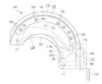
本発明の一実施の形態に係る安全帯用発報装置について図面を参照して説明する。図1は安全帯用発報装置の正面図、図2は安全帯用発報装置の上面図、図3は安全帯用発報装置の左側面図、図4は安全帯用発報装置をフックに装着した様子を示す正面図、図5は安全帯用発報装置をフックに装着した状態で図2のA線の位置で切断した断面図、図6は図4のB線で切断した断面図、図7は安全帯用発報装置の装着先であるフックの正面図である。 A safety belt alarm device according to one embodiment of the present invention will be described with reference to the drawings. FIG. 1 is a front view of the alarm device for safety belt, FIG. 2 is a top view of the alarm device for safety belt, FIG. 3 is a left side view of the alarm device for safety belt, and FIG. FIG. 5 is a front view showing a state of being attached to the hook, FIG. 5 is a cross-sectional view taken along a line A in FIG. 2 in a state where the safety belt alarm device is attached to the hook, and FIG. 6 is a sectional view taken along a line B in FIG. FIG. 7 is a cross-sectional view, and FIG. 7 is a front view of a hook to which the safety band alarm device is mounted.
まず、図7を参照して、安全帯用発報装置の装着先であるフックの構成について説明する。フック200は、図7に示すように、鉤状部材210と、鉤状部材210の開口に対して開閉動作をする外れ止め部材220と、外れ止め部材220の開閉動作を制限するロック部材230とを備えている。
First, with reference to FIG. 7, the configuration of a hook to which the safety belt alarm device is mounted will be described. As shown in FIG. 7, the
鉤状部材210は、親綱や足場の手すりなど被掛止物を開口の内側に引っ掛けるよう板状部材を湾曲させた形状を有している。鉤状部材210の一端側は、安全帯のロープ(図示省略)と連結するための連結孔211が形成されている。
The hook-
外れ止め部材220は、その一端側をリベット221により、鉤状部材210の開口の内側において回動自在に付設されている。外れ止め部材220の他端側は、鉤状部材210の先端部の内側に係止するよう形成されている。外れ止め部材220は、バネ222により鉤状部材210の開口を閉鎖する方向に付勢されている。
One end of the retaining
ロック部材230は、その一端側をリベット231により、鉤状部材210の外側において回動自在に付設されている。ロック部材230は、バネ232により鉤状部材210の外側に向けて付勢されている。ロック部材230には、スライド溝233が形成されている。このスライド溝233には、前記外れ止め部材220の一部と重なっており、外れ止め部材220に設けられたリベット223が挿通している。スライド溝233は、外れ止め部材220が鉤状部材210の開口を閉鎖した状態にあるとき、ロック部材230の回動にしたがって外れ止め部材220のリベット223がスライド溝233内を移動するよう形成されている。さらに、スライド溝233は、ロック部材230を鉤状部材210方向に回動させた状態にあるとき、外れ止め部材220の回動にしたがってリベット223がスライド溝233内を移動するよう形成されている。
One end of the
次に、本実施の形態に係る安全帯用発報装置の構成について説明する。図1〜図6に示すように、安全帯用発報装置100は、ケース110と、フック200が被掛止物10に掛けられたことを検知する検知手段を構成するレバー120及びスイッチ130と、報知動作を行う報知手段であるスピーカ140及び複数のLED150と、前記検知手段の検知信号に基づき被掛止物10に掛けられたことを報知するよう前記報知手段を制御する報知制御手段である制御回路160と、を備えている。
Next, the configuration of the safety zone alarm device according to the present embodiment will be described. As shown in FIGS. 1 to 6, the
ケース110は、フック200の鉤状部材210の一部、具体的には湾曲部を、その内面が露出した状態で外側縁部から覆うように、断面略U字状に形成されている。フック200を被掛止物10に掛けた際に当該被掛止物10がケース110に衝突しない又は衝突による衝撃が小さくなるように、鉤状部材210の湾曲部を覆う箇所のケース110内縁は、鉤状部材210の湾曲部の内縁と一致またはやや外側に位置している。換言すれば、ケース110の内縁の稜線は、フック200の鉤状部材210の一部、具体的には湾曲部の内側縁部の稜線と一致する又はやや内側に位置した状態となっている。ケース110は、鉤状部材210をその厚み方向に挟んだ状態で両側から押圧する押圧部材(本実施の形態では複数のネジ111)により、前記鉤状部材210に着脱自在に固定可能となっている。
The
ケース110には、鉤状部材210の連結孔211側の端部に、スピーカ140・スイッチ130・制御回路160を収納する箱部112が形成されている。さらに、箱部112には、安全帯の人体ベルト又は作業服のベルトなど、墜落防止のために用いるものとは異なる被掛止物に引っ掛けるための引っ掛け片113が外側に向けて形成されている。
In the
ケース110の湾曲部の内側であって左右一方の底面には、レバー120を収容するための溝114が形成されている。レバー120は、前記溝114内においてリベット115によって回動自在に設けられている。レバー120は、レバー120の端部に設けられたバネ116により鉤状部材210の湾曲部の内側方向に付勢されている。レバー120の可動域は、レバー120の端部と当接する係止片117a,117bにより規制されている。ここで、レバー120は、通常時は、フック200が被掛止物10に掛けられた際に当該被掛止物10に当接して回動するよう、フック200の鉤状部材210の湾曲部の内側縁部の稜線よりもやや内側に位置している。
A
スイッチ130は、レバー120が被掛止物10と当接して回動したことを検知するセンサである。スイッチ130は、レバー120が回動した際に、レバー120の端部がスイッチ130のアクチュエータを操作するように配置されている。
The
ケース110の上面及び両側面には、鉤状部材210の湾曲にそって形成された凹部118及び119が形成されている。各凹部118及び119の底面には、発光素子であるLED150が互いに間隔をおいて複数設けられている。凹部118及び119の深さは、LED150の頭部がケース110の外面から露出する深さに形成されている。これにより、LED150の視認性を確保するとともに、LED150が障害物にあたって壊れることから保護している。
スピーカ140は、例えば、圧電スピーカからなる。ケース110の箱部112にはスピーカ140から発せられる音を外部に放出するための音響孔(図示省略)が設けられている。
The
図8に安全帯用発報装置の回路図を示す。図8に示すように、制御回路160にはスイッチ130とスピーカ140とLED150が接続されている。制御回路160は、図示省略のバッテリ及び電源スイッチを備えており、電源スイッチをオンにしてバッテリからの電力供給により動作する。制御回路160は、スイッチ130用の入力回路、スピーカ140の駆動回路、LED150用の駆動回路を含む。
FIG. 8 shows a circuit diagram of the alarm device for the safety belt. As shown in FIG. 8, a
制御回路160は、スイッチ130によりレバー120の回動を検知すると、スピーカ140及びLED150を用いてフック200が被掛止物10に掛けられた旨を報知するよう所定の報知制御を行う。具体的には、例えば「安全です」なる音声データを所定の記憶部に予め記憶しておき、当該音声データを所定回数(例えば2回)スピーカ140から出力するよう制御する。また例えば、全てのLED150を所定時間(例えば3秒間)、所定の間隔で点滅させる制御を行う。なお、音による報知(聴覚に訴える報知)と光による報知(視覚に訴える報知)は何れか一方だけ実施してもよいし、本実施の形態のように両方を実施するようにしてもよい。
When the
このような安全帯用発報装置100は、図4に示すように、フック200の鉤状部材210の湾曲部に外側から被せ、ネジ111により固定することによりフック200に装着される。作業者は、高所での作業前や移動時など安全帯の使用前に、安全帯用発報装置100の電源がオンにし、安全帯用発報装置100の引っ掛け片113を、安全帯の人体ベルト又は作業服のベルトなど、墜落防止のために用いるものとは異なる被掛止物に引っ掛けておく。ここで、安全帯の使用前では、安全帯用発報装置100は作動しないので、誤った報知を防止することができる。
As shown in FIG. 4, such a safety
そして、作業員が安全帯を使用すべく親綱や足場の手すりなどにフック200を引っ掛けると、安全帯用発報装置100のレバー120が回動して、スピーカ140及びLED150が報知動作を行う。これにより、作業員に対して、安全帯のフック200が確実に使用されていることを認識させることができる。
Then, when the worker hooks the
このように、本実施の形態に係る安全帯用発報装置100によれば、ケース110が、安全帯のフック200の鉤状部材210の一部をその内側縁部が露出した状態で外側縁部から覆うように形成されているので、専用のフックを用意することなく、既存のフックに取り付けるだけで使用することができる。また、検知手段と報知手段と報知制御手段とが1つのケース110に設けられており、他の装置等を必要としない簡便な構成なので、製造コストを抑えることができるとともに、使用時の利便性も高いものとなる。
As described above, according to the
また、本実施の形態に係る安全帯用発報装置100によれば、ケース110は、鉤状部材210をその厚み方向に挟んだ状態で両側から押圧する押圧部材であるネジ111により、鉤状部材210に固定可能となっているので、安全帯用発報装置100のフック200に対する着脱を確実且つ容易に行うことができる。
In addition, according to the
また、本実施の形態に係る安全帯用発報装置100によれば、ケース110には、安全帯の人体ベルト又は作業服のベルトなどの、他の被掛止物に引っ掛けるための引っ掛け片113が形成されているので、安全帯の使用時以外に報知動作が行われることを防止できる。
In addition, according to the
また、本実施の形態に係る安全帯用発報装置100によれば、LED150はケース110に形成された凹部118及び119の底面に、LED150の頭部がケース110の外面から露出するように配置されているので、LED150の視認性を確保できるととものに、LED150が障害物にあたって壊れることから保護することができる。
Further, according to safety
以上、本発明の一実施の形態について詳述したが、本発明はこれに限定されるものではない。例えば、上記実施の形態ではケース110に引っ掛け片113を形成したが、当該引っ掛け片113は省略してもよい。
As mentioned above, although one Embodiment of this invention was described in detail, this invention is not limited to this. For example, in the above embodiment, the
また、上記実施の形態では、フック200が被掛止物10に掛けられたことを検知する手段としてレバー120及びスイッチ130を用いたが、光センサによりレバー120の回動を検出したり、感圧センサを用いたりするなど、他のセンサを用いてもよい。
Further, in the above-described embodiment, the
また、上記実施の形態では、光による報知手段として、複数のLED150をケース110の上面及び側面に設けたが、LED150の数や設置場所は不問である。また発光素子としてLED以外のものを用いてもよい。
Further, in the above-described embodiment, the plurality of
また、上記実施の形態では、ケース110を鉤状部材210に着脱自在に固定する手段として鉤状部材210を挟み込むように押圧するネジ111を用いたが、ケース110に引っ掛け片を形成して鉤状部材210を支持するなど、他の構造によりケース110と鉤状部材210に着脱自在に固定するようにしてもよい。
Further, in the above-described embodiment, the
10…被掛止物
100…安全帯用発報装置
110…ケース
118,119…凹部
120…レバー
130…スイッチ
140…スピーカ
150…LED
160…制御回路
200…フック
210…鉤状部材
220…外れ止め部材
230…ロック部材
DESCRIPTION OF
160: control circuit 200: hook 210: hook-like member 220: retaining member 230: locking member
Claims (7)
前記鉤状部材の一部をその内側縁部が露出した状態で外側縁部から覆うように形成された着脱自在のケースと、
前記ケースに設けられた、
前記フックが第1被掛止物に掛けられたことを検知する検知手段と、
報知動作を行う報知手段と、
前記検知手段の検知信号に基づき第1被掛止物に掛けられたことを報知するよう前記報知手段を制御する報知制御手段と、を備えた
ことを特徴とする安全帯用発報装置。 A safety belt alarm device used by being attached to a safety belt including a hook having a hook-like member,
A detachable case formed to cover a part of the hook-shaped member from the outer edge with the inner edge exposed,
Provided in the case,
Detecting means for detecting that the hook is hooked on the first hooked object;
An informing means for performing an informing operation;
And a notification control means for controlling the notification means so as to notify that the first hanging object has been hung on the basis of the detection signal of the detection means.
ことを特徴とする請求項1記載の安全帯用発報装置。 The safety case according to claim 1, wherein the case is fixable to the hook-shaped member by a pressing member that presses the hook-shaped member from both sides while sandwiching the hook-shaped member in a thickness direction thereof. Information device.
ことを特徴とする請求項1又は2記載の安全帯用発報装置。 The safety case according to claim 1 or 2, wherein the case is formed with a hook for hooking on a second object to be hung such as a human belt of a safety belt or a belt of work clothes. Information device.
ことを特徴とする請求項1乃至3何れか1項記載の安全帯用発報装置。 The detecting means includes a lever that rotates when the hook is hooked on the first hooked object and contacts the first hooked object, and a sensor that detects the rotation of the lever. The alarm device for a safety belt according to any one of claims 1 to 3, characterized in that:
前記報知制御手段は音声を前記音響装置から出力する
ことを特徴とする請求項1乃至4何れか1項記載の安全帯用発報装置。 The notification means includes an audio device,
The alarm device for a safety belt according to any one of claims 1 to 4, wherein the notification control unit outputs a sound from the audio device.
ことを特徴とする請求項1乃至5何れか1項記載の安全帯用発報装置。 The alarm device for a safety belt according to any one of claims 1 to 5, wherein the notifying unit includes a light emitting element provided to be exposed on an outer surface of the case.
ことを特徴とする請求項6記載の安全帯用発報装置。
A recess is formed in the outer surface of the case, and the light emitting element is arranged on the bottom surface of the recess with its head exposed from the outer surface of the case. Alarm device.
Priority Applications (2)
| Application Number | Priority Date | Filing Date | Title |
|---|---|---|---|
| JP2018173456A JP2020043964A (en) | 2018-09-18 | 2018-09-18 | Alarming device for safety belt |
| JP2021124295A JP7122780B2 (en) | 2018-09-18 | 2021-07-29 | Alarm device for safety belt |
Applications Claiming Priority (1)
| Application Number | Priority Date | Filing Date | Title |
|---|---|---|---|
| JP2018173456A JP2020043964A (en) | 2018-09-18 | 2018-09-18 | Alarming device for safety belt |
Related Child Applications (1)
| Application Number | Title | Priority Date | Filing Date |
|---|---|---|---|
| JP2021124295A Division JP7122780B2 (en) | 2018-09-18 | 2021-07-29 | Alarm device for safety belt |
Publications (1)
| Publication Number | Publication Date |
|---|---|
| JP2020043964A true JP2020043964A (en) | 2020-03-26 |
Family
ID=69899204
Family Applications (2)
| Application Number | Title | Priority Date | Filing Date |
|---|---|---|---|
| JP2018173456A Pending JP2020043964A (en) | 2018-09-18 | 2018-09-18 | Alarming device for safety belt |
| JP2021124295A Active JP7122780B2 (en) | 2018-09-18 | 2021-07-29 | Alarm device for safety belt |
Family Applications After (1)
| Application Number | Title | Priority Date | Filing Date |
|---|---|---|---|
| JP2021124295A Active JP7122780B2 (en) | 2018-09-18 | 2021-07-29 | Alarm device for safety belt |
Country Status (1)
| Country | Link |
|---|---|
| JP (2) | JP2020043964A (en) |
Cited By (2)
| Publication number | Priority date | Publication date | Assignee | Title |
|---|---|---|---|---|
| JP2020192077A (en) * | 2019-05-28 | 2020-12-03 | サンコー株式会社 | Locked state detection device of hook of safety belt |
| KR20210117887A (en) * | 2020-03-19 | 2021-09-29 | 주식회사 아이오티융복합연구소 | Device for detecting the fastening of safety hooks |
Families Citing this family (2)
| Publication number | Priority date | Publication date | Assignee | Title |
|---|---|---|---|---|
| KR102431043B1 (en) * | 2022-07-12 | 2022-08-10 | (주)일신이앤씨 | Work vest with fall prevention safety device for safety diagnosis of facilities |
| JP7271027B1 (en) | 2022-07-14 | 2023-05-11 | 株式会社つくし工房 | Lanyards and light emitting devices for lanyards |
Family Cites Families (4)
| Publication number | Priority date | Publication date | Assignee | Title |
|---|---|---|---|---|
| JP5079637B2 (en) * | 2008-08-22 | 2012-11-21 | 藤井電工株式会社 | Safety belt |
| JP5307654B2 (en) * | 2009-07-08 | 2013-10-02 | 東日本旅客鉄道株式会社 | Safety belt check device |
| JP5116815B2 (en) | 2009-10-20 | 2013-01-09 | 藤井電工株式会社 | Safety belt and its usage confirmation system |
| JP6315188B2 (en) | 2014-04-21 | 2018-04-25 | 株式会社システック | Hooking detection device with postponing alarm postponing means |
-
2018
- 2018-09-18 JP JP2018173456A patent/JP2020043964A/en active Pending
-
2021
- 2021-07-29 JP JP2021124295A patent/JP7122780B2/en active Active
Cited By (4)
| Publication number | Priority date | Publication date | Assignee | Title |
|---|---|---|---|---|
| JP2020192077A (en) * | 2019-05-28 | 2020-12-03 | サンコー株式会社 | Locked state detection device of hook of safety belt |
| JP7261470B2 (en) | 2019-05-28 | 2023-04-20 | サンコー株式会社 | Safety belt hook locking state detector |
| KR20210117887A (en) * | 2020-03-19 | 2021-09-29 | 주식회사 아이오티융복합연구소 | Device for detecting the fastening of safety hooks |
| KR102552630B1 (en) * | 2020-03-19 | 2023-07-13 | 주식회사 아이오유 | Device for detecting the fastening of safety hooks |
Also Published As
| Publication number | Publication date |
|---|---|
| JP7122780B2 (en) | 2022-08-22 |
| JP2021168983A (en) | 2021-10-28 |
Similar Documents
| Publication | Publication Date | Title |
|---|---|---|
| JP2020043964A (en) | Alarming device for safety belt | |
| US9359171B1 (en) | Safety system for a lift installation and safety helmet as individual component of such a safety system | |
| US10231518B2 (en) | Control docking station for one or two stage locking mechanism | |
| US20150130604A1 (en) | System and Method For Notifying The Presence of an Unattended Child | |
| US9779612B2 (en) | Wireless item loss prevention system | |
| KR20120083946A (en) | Supervisory apparatus of wearing the safety helmet in the construction field | |
| JP5382453B2 (en) | Contact accident prevention system between construction machines and workers | |
| EP3314589B1 (en) | An alert system and method | |
| KR102448783B1 (en) | Smart safety helmet and safety helmet wearing managing apparatus of using thereof | |
| US9390609B2 (en) | Monitoring apparatus | |
| KR20100050002A (en) | Fireman helmet and method for controlling there of | |
| JP2009167587A (en) | Helmet with alarm function | |
| US20200008757A1 (en) | EARS: Emergency Alert Response System Monitoring Device | |
| KR20210101767A (en) | Safety loop device | |
| KR20210022264A (en) | Safety Belt Unit For High Place Work | |
| KR102205608B1 (en) | Smart wearable system to protect workers' safety | |
| KR102025379B1 (en) | Wearable apparatus for safety supervisory of construction field workers | |
| KR100975289B1 (en) | alarm system for train access using bone conduction speaker and method thereof | |
| KR20190092730A (en) | Harness for safety | |
| KR102618229B1 (en) | Wearer monitoring module for hard hat and safety monitoring system using the same | |
| US8717161B1 (en) | Lockout for hydrogen sulfide monitoring system | |
| US11042129B2 (en) | Redundant wireless safety system for manufacturing environment | |
| GB2573835A (en) | Communicator | |
| JP7261470B2 (en) | Safety belt hook locking state detector | |
| KR102651763B1 (en) | Smart safety management system for wearing safety helmet |
Legal Events
| Date | Code | Title | Description |
|---|---|---|---|
| A521 | Written amendment |
Free format text: JAPANESE INTERMEDIATE CODE: A523 Effective date: 20180926 |
|
| A521 | Written amendment |
Free format text: JAPANESE INTERMEDIATE CODE: A821 Effective date: 20180926 |