JP2020036734A - Biological information management system, management device, and display method - Google Patents
Biological information management system, management device, and display method Download PDFInfo
- Publication number
- JP2020036734A JP2020036734A JP2018165101A JP2018165101A JP2020036734A JP 2020036734 A JP2020036734 A JP 2020036734A JP 2018165101 A JP2018165101 A JP 2018165101A JP 2018165101 A JP2018165101 A JP 2018165101A JP 2020036734 A JP2020036734 A JP 2020036734A
- Authority
- JP
- Japan
- Prior art keywords
- terminal device
- information
- alarm
- alarm information
- biological information
- Prior art date
- Legal status (The legal status is an assumption and is not a legal conclusion. Google has not performed a legal analysis and makes no representation as to the accuracy of the status listed.)
- Granted
Links
Images


Landscapes
- Measuring And Recording Apparatus For Diagnosis (AREA)
Abstract
【課題】端末装置のユーザーがアラーム情報を確認したか否かを管理者が容易かつ的確に知ることができるシステムを提供すること。【解決手段】生体情報管理システム100は、セントラルモニター10など生体情報モニターから送信されたアラーム情報を受信して表示可能な端末装置130と、生体情報モニターから送信されたアラーム情報を記憶する記憶部111、端末装置から送信された応答信号を受信する受信部(通信部112)、及び、記憶部111に記憶されたアラーム情報と応答信号との関係に基づいて端末装置130によるアラーム情報の確認履歴を作成する確認履歴作成部113を有する上位サーバー110と、を備える。【選択図】図1A system is provided in which an administrator can easily and accurately know whether or not a user of a terminal device has confirmed alarm information. A biological information management system (100) includes a terminal device (130) capable of receiving and displaying alarm information transmitted from a biological information monitor such as a central monitor (10), and a storage unit that stores alarm information transmitted from the biological information monitor. 111, a receiving unit (communication unit 112) that receives a response signal transmitted from the terminal device, and a confirmation history of alarm information by the terminal device 130 based on the relationship between the alarm information and the response signal stored in the storage unit 111 and a host server 110 having a confirmation history creation unit 113 that creates a [Selection drawing] Fig. 1
Description
本発明は、生体情報管理システム、及び、それに用いられる管理装置、表示方法に関する。 The present invention relates to a biological information management system, a management device used for the system, and a display method.
生体情報モニターは、生体情報(例えば、心電図、血圧及び酸素飽和度など)の計測値及び波形を、表示部に一括表示することができる。生体情報モニターの例としては、病室などのベッドサイドに設置して使用されるベッドサイドモニター及びナースステーション(スタッフステーションとも呼ばれている)などに設置して使用されるセントラルモニターなどがある。生体情報モニターにより表示された計測値及び波形を見ることで、医療従事者(医師及び看護師など)は、患者の容体を把握することができる。 The biological information monitor can collectively display measured values and waveforms of biological information (for example, electrocardiogram, blood pressure, oxygen saturation, and the like) on the display unit. Examples of the biological information monitor include a bedside monitor installed and used at the bedside of a hospital room and the like and a central monitor installed and used at a nurse station (also called a staff station). By looking at the measured values and waveforms displayed by the biological information monitor, medical staff (such as doctors and nurses) can grasp the condition of the patient.
また、生体情報モニターは一般的に、アラーム機能を備えている。アラーム機能とは、患者の生体情報を閾値と比較することで生体情報の異常を検知し、異常を検知したときに表示や音によってアラーム出力を行う機能である。このアラーム機能により、医療従事者は、患者の異常時に適切な措置を迅速にとることができる。このようなアラーム機能を備えた生体情報モニターは、例えば特許文献1に記載されている。 The biological information monitor generally has an alarm function. The alarm function is a function of detecting an abnormality of the biological information by comparing the biological information of the patient with a threshold, and outputting an alarm by display or sound when the abnormality is detected. With this alarm function, the medical staff can quickly take appropriate measures when the patient is abnormal. A biological information monitor having such an alarm function is described in Patent Document 1, for example.
生体情報モニターのアラームは、例えばナースコールシステムに送信される。ナースコールシステムでは、生体情報モニターからアラームを受信すると、看護師が携帯する携帯電話などにアラームが発生した患者IDや生体パラメータ名(HRアラーム、VFアラーム、SpO2アラームなど)を送信する。これにより、看護師は、アラームが発生した患者の下に急行することができる。 The alarm of the biological information monitor is transmitted to, for example, a nurse call system. In the nurse call system, to send and receive alarms from the biological information monitor, mobile phone patient ID or biological parameter name alarm occurs, such as nurses to carry a (HR alarm, VF alarm, SpO 2 alarm, etc.). This allows the nurse to rush under the alarmed patient.
また、従来の生体情報管理システムとして、生体情報モニターが上位サーバーに接続され、さらにこの上位サーバーに電子カルテシステムが接続された、いわゆる統合型の生体情報管理システムが実現されている。この生体情報管理システムでは、上位サーバーに、各患者の生体情報やアラーム履歴が各患者の患者情報に紐付けられて記録される。この結果、例えば電子カルテシステムのユーザーは上位サーバーにアクセスすることで、各患者の生体情報やアラーム履歴を見ることができるようになっている。 As a conventional biological information management system, a so-called integrated biological information management system in which a biological information monitor is connected to an upper server and an electronic medical record system is connected to the upper server has been realized. In this biological information management system, the biological information and alarm history of each patient are recorded in the host server in association with the patient information of each patient. As a result, for example, a user of the electronic medical record system can view the biological information and the alarm history of each patient by accessing the host server.
ところで、従来のナースコールシステムでは、看護師がアラーム情報を見たか否かを後日確認するために、看護師の携帯電話からの応答信号をログ情報として記録して残すようになされたものがある。看護師がアラーム情報を見たか否かの確認は、病院の管理者などにとって重要である。 By the way, in a conventional nurse call system, a response signal from a mobile phone of a nurse is recorded and left as log information in order to confirm at a later date whether or not the nurse has seen the alarm information. . It is important for a hospital manager or the like to confirm whether a nurse has viewed alarm information.
しかしながら、従来のシステムでは、応答信号がログ情報として記録されているだけであり、このログ情報から、どのアラーム情報を見たかを把握するには非常に煩雑な手間がかかった。 However, in the conventional system, only the response signal is recorded as log information, and it is very troublesome to grasp which alarm information is viewed from the log information.
本発明は、以上の点を考慮してなされたものであり、端末装置のユーザーがアラーム情報を確認したか否かを管理者が容易かつ的確に知ることができるようになる生体情報管理システム、管理装置及び表示方法を提供する。 The present invention has been made in view of the above points, a biological information management system that allows an administrator to easily and accurately know whether or not the user of the terminal device has confirmed the alarm information, A management device and a display method are provided.
本発明の生体情報管理システムの一つの態様は、
生体情報モニターから送信されたアラーム情報を受信して表示可能な端末装置と、
前記生体情報モニターから送信された前記アラーム情報を記録する記録部と、前記端末装置から送信された応答信号を受信する受信部と、前記記録部に記録されたアラーム情報と前記応答信号との関係に基づいて前記端末装置による前記アラーム情報の確認履歴を作成する確認履歴作成部とを有する管理装置と、
を具備する。
One embodiment of the biological information management system of the present invention,
A terminal device capable of receiving and displaying the alarm information transmitted from the biological information monitor,
A recording unit that records the alarm information transmitted from the biological information monitor, a receiving unit that receives a response signal transmitted from the terminal device, and a relationship between the alarm information recorded in the recording unit and the response signal A management device having a confirmation history creating unit that creates a confirmation history of the alarm information by the terminal device based on
Is provided.
本発明の管理装置の一つの態様は、
生体情報モニターのアラーム情報を端末装置に送信するシステムにおける管理装置であって、
前記生体情報モニターから送信された前記アラーム情報を記録する記録部と、
前記端末装置から送信された応答信号を受信する受信部と、
前記記録部に記録されたアラーム情報と前記応答信号との関係に基づいて、前記端末装置による前記アラーム情報の確認履歴を作成する確認履歴作成部と、
を具備する。
One aspect of the management device of the present invention is:
A management device in a system that transmits alarm information of a biological information monitor to a terminal device,
A recording unit that records the alarm information transmitted from the biological information monitor,
A receiving unit that receives a response signal transmitted from the terminal device,
A confirmation history creating unit that creates a confirmation history of the alarm information by the terminal device based on a relationship between the alarm information and the response signal recorded in the recording unit;
Is provided.
本発明の表示方法の一つの態様は、
生体情報モニターのアラーム情報を端末装置に送信するシステムにおける表示方法であって、
前記生体情報モニターから送信された前記アラーム情報を記憶する記憶ステップと、
前記端末装置から送信された応答信号を受信する受信ステップと、
前記記憶ステップで記憶したアラーム情報と前記応答信号との関係に基づいて、前記端末装置による前記アラーム情報の確認履歴を作成する確認履歴作成ステップと、
前記確認履歴を表示する表示ステップと、
を含む。
One embodiment of the display method of the present invention is:
A display method in a system for transmitting alarm information of a biological information monitor to a terminal device,
A storage step of storing the alarm information transmitted from the biological information monitor,
A receiving step of receiving a response signal transmitted from the terminal device,
A confirmation history creation step of creating a confirmation history of the alarm information by the terminal device based on a relationship between the alarm information and the response signal stored in the storage step;
A display step of displaying the confirmation history;
including.
本発明によれば、記録されたアラーム情報と端末装置からの応答信号との関係に基づいて、端末装置によるアラーム情報の確認履歴が作成されるので、端末装置のユーザーがアラーム情報を見たか否かを管理者が容易かつ的確に知ることができるようになる。 According to the present invention, since the confirmation history of the alarm information by the terminal device is created based on the relationship between the recorded alarm information and the response signal from the terminal device, it is determined whether the user of the terminal device has viewed the alarm information. Can be easily and accurately known to the administrator.
以下、本発明の実施の形態を、図面を参照して説明する。 Hereinafter, embodiments of the present invention will be described with reference to the drawings.
<1>全体構成
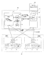
図1は、本発明の実施の形態に係る医用システムの全体構成を示す概略的ブロック図である。図1の医用システムは、生体情報モニタリングシステム20及び生体情報管理システム100を有する。
<1> Overall Configuration FIG. 1 is a schematic block diagram showing the overall configuration of a medical system according to an embodiment of the present invention. The medical system in FIG. 1 includes a biological
図1の医用システムは、各病棟に設けられた生体情報モニターが生体情報管理システム100の上位サーバー110によって統合されたいわゆる統合型システムである。
The medical system in FIG. 1 is a so-called integrated system in which biological information monitors provided in each ward are integrated by a
各病棟A、Bには、セントラルモニター10、ベッドサイドモニター(BSモニター)11、テレメーター送信機12が設けられており、ベッドサイドモニター11及びテレメーター送信機12で取得された患者の生体情報がセントラルモニター10に集約される。これらセントラルモニター10、ベッドサイドモニター11及びテレメーター送信機12は、全て生体情報モニターと呼ぶことができる。
Each ward A, B is provided with a
各病棟A、Bのセントラルモニター10に集約された生体情報及びアラーム情報は、上位サーバー110の記憶部111に記憶される。具体的には、上位サーバー110の記憶部111には、患者ID(患者識別情報)に紐付けられて、各患者の生体情報及びアラーム情報が記憶される。生体情報には、心電図などの波形や、計測値が含まれる。アラーム情報には、アラームが発生した、患者ID、生体パラメータ名(アラーム名と呼ぶこともある)及び時刻などが含まれる。
The biological information and the alarm information collected on the
図1の医用システムは、ナースコールシステムや電子カルテシステムなどの他システム120を有する。他システム120はセントラルモニター10及び上位サーバー110と有線で接続されている。なおこれらは無線で接続されていてもよい。
The medical system of FIG. 1 has another
セントラルモニター10は、アラームが発生すると、アラーム発生情報を他システム120に送信する。このアラーム発生情報には、患者ID、アラーム名(つまりアラームが発生した生体情報パラメータ名)、アラーム発生時刻などが含まれる。なお、「アラーム発生情報」は「アラーム情報」に含まれる。本明細書では、アラーム発生情報を含めてアラーム情報と呼ぶことがある。
When an alarm occurs, the
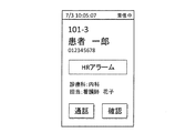
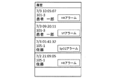
他システム120は、セントラルモニター10からアラーム発生情報を受信すると、アラームの内容を表示又は記録する。具体的には、他システム120がナースコールシステムの場合には、看護師の携帯電話などに、図2に示したような画像が表示される。また、他システムが電子カルテシステムの場合には、電子カルテシステムのサーバーなどに図3に示したようなアラーム着信履歴が記憶され、これを表示可能である。
Upon receiving the alarm occurrence information from the
図2に示したように、ナースコールシステムの携帯電話には、着信日時「7/3 10:05:07」、部屋番号「101-3」、患者氏名「患者一郎」、患者ID「012345678」、アラーム名「HRアラーム」、その他の情報「診療科:内科 担当:看護師花子」、通話ボタン「通話」、確認ボタン「確認」などが表示される。 As shown in FIG. 2, the mobile phone of the nurse call system has an incoming date and time “7/3 10:05:07”, a room number “101-3”, a patient name “patient Ichiro”, and a patient ID “012345678”. , An alarm name "HR alarm", and other information "medical department: internal medicine charge: nurse Hanako", a call button "call", a confirmation button "confirm", and the like are displayed.
図3に示したように、電子カルテシステムの端末の表示部には、着信日時「7/3 10:05:07」、部屋番号「101-3」、患者氏名「患者一郎」、アラーム名「HRアラーム」などが表示される。勿論、図3に示したようなアラーム着信履歴は、ナースコールシステムにおいて表示されてもよい。 As shown in FIG. 3, the display unit of the terminal of the electronic medical record system displays the date and time of the incoming call “7/3 10:05:07”, the room number “101-3”, the patient name “patient Ichiro”, and the alarm name “ "HR alarm" is displayed. Of course, the alarm reception history as shown in FIG. 3 may be displayed in the nurse call system.
加えて、生体情報管理システム100は、端末装置130を有する。本実施の形態の端末装置130は、スマートフォンなどの無線端末装置である。端末装置130は、パソコンなどであってもよい。本実施の形態では、主に端末装置130が無線端末装置である場合について説明する。端末装置130は、表示部131及び通信部132を有する。勿論、端末装置130は、図示しない操作入力部や制御部などの他の構成要素も有する。通信部132は、上位サーバー110と無線通信が可能である。
In addition, the biological
他システム120は、セントラルモニター10からアラーム発生情報を受信すると、このアラーム発生情報を上位サーバー110に送信する。より具体的には、他システム120は、アラーム発生情報と、端末装置130の識別情報であるユーザー情報とを、上位サーバー110に送る。
Upon receiving the alarm occurrence information from the
上位サーバー110の通信部112は、アラーム発生情報及び端末装置130の識別情報を受信すると、記憶部111に記憶された情報の中から、アラーム発生情報に対応する生体情報を読み出して、この生体情報をアラーム情報とともに、ユーザー情報に対応する端末装置130に無線送信する。
Upon receiving the alarm occurrence information and the identification information of the
端末装置130は、通信部132によってアラーム情報及び生体情報を無線受信すると、このアラーム情報及び生体情報を表示部131に表示する。
When the
なお、他システム120に送信されるアラーム発生情報と、記憶部111に記憶されるアラーム情報は、同じものであってもよく、記憶部111に記憶されるアラーム情報はアラーム発生情報よりも詳しい情報であってもよい。実際上、他システム120に送信されるアラーム発生情報はセントラルモニター10から他システム120への通知が必要であると判断されたアラーム情報であるが、記憶部111に記憶されるアラーム情報は他システム120への通知が必要であると判断されたアラーム情報に加えて他システム120への通知が不要であると判断されたアラーム情報も含んでいる。
Note that the alarm occurrence information transmitted to the
つまり、記憶部111には、実際に他システム120や端末装置130に送信されたアラーム情報と、他システム120や端末装置130には送信されなかったアラーム情報との両方が識別可能に記憶されている。
That is, in the
本実施の形態の上位サーバー110は、セントラルモニター10などの生体情報モニターから端末装置130にアラーム情報を送信するシステムにおける管理装置としての機能も有する。上位サーバー110は、生体情報モニターから送信されたアラーム情報及び生体情報を記憶する記憶部111と、端末装置130から送信された応答信号を受信する受信部としての通信部112と、記憶部111に記憶されたアラーム情報及び生体情報と応答信号との関係に基づいて、端末装置130によるアラーム情報の確認履歴を作成する確認履歴作成部113と、を有する。確認履歴作成部113で作成された確認履歴は、表示部114に表示することができる。なお、確認履歴作成部113で作成された確認履歴は、生体情報管理システム100内の他の端末や、外部の端末で表示又は印刷されるようにしてもよい。
The
具体的に説明すると、端末装置130は、端末装置130のユーザーがアラーム情報や生体情報を確認したことを示す応答信号を上位サーバー110に送信する。この応答信号は、例えばユーザーが図2の「確認」のボタンをタッチ操作した際に端末装置130から送信される。ただし、応答信号が送信されるトリガーはこれに限らず、例えばユーザーがアラーム情報や生体情報の画面を選択して表示させたタイミングで送信されてもよい。
Specifically, the
上位サーバー110は、この応答信号を受信すると、これを確認履歴作成部113に送る。確認履歴作成部113は、記憶部111に記憶されているアラーム情報及び生体情報と、応答信号が送信された端末装置130のユーザー情報と、に基づいて、ユーザーがアラーム情報や生体情報を確認したか否かを示す確認履歴を作成する。
Upon receiving the response signal, the
ここで、上位サーバー110は、他システム120から入力されたユーザー情報(端末識別情報)を記憶部111に記憶するようになっており、これにより、上位サーバー110の記憶部111はどの端末にどのアラーム情報及び生体情報が送信されたかを示す情報が記憶されている。つまり、上位サーバー110は、端末装置130へのアラーム送信履歴を記憶している。確認履歴作成部113は、このアラーム送信履歴と応答信号とから、どの端末装置でどのアラーム情報や生体情報が確認されたかを示す確認履歴を作成する。
Here, the
<2>端末装置における表示
図4、図5及び図6は、端末装置130が表示するアラーム情報及び生体情報の表示例を示す。
<2> Display on Terminal Device FIGS. 4, 5, and 6 show display examples of alarm information and biological information displayed by the
図4及び図5の表示例は、アラーム表示モード(図4)と最新表示モード(図5)とを切り替えることができる表示例である。この表示例では、画面に「アラーム」及び「最新」のボタンが表示され、ユーザーが「アラーム」のボタンをタッチ操作すると図4の画像が表示され、ユーザーが「最新」のボタンをタッチ操作すると図5の画像が表示される。 The display examples of FIGS. 4 and 5 are display examples that can switch between the alarm display mode (FIG. 4) and the latest display mode (FIG. 5). In this display example, the “alarm” and “latest” buttons are displayed on the screen, and when the user touches the “alarm” button, the image of FIG. 4 is displayed. When the user touches the “latest” button, The image of FIG. 5 is displayed.
図4及び図5の画像において、画面の上部には患者の部屋番号「101-3」、患者氏名「患者一郎」、アラーム名「HR」、アラーム通知からの経過時間「16秒前」(図4)、「1分20秒前」(図5)が表示される。これらの表示情報は、図2及び図3の表示例からも明らかなように、従来のナースコールシステムの携帯電話や電子カルテシステムの画面にも表示されていたものである。
In the images of FIGS. 4 and 5, the patient's room number “101-3”, the patient name “Patient Ichiro”, the alarm name “HR”, and the elapsed time from the alarm notification “16 seconds before” (FIG. 4) "1
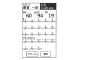
本実施の形態の端末装置130においては、この従来の表示に加えて、生体情報も表示される。具体的には、図4のアラーム表示モードでは、アラーム発生時の計測値「HR30 SpO283 RR15」、心電図(図の例の場合、II誘導)、アラーム通知時点を示すマーク「◆HR」、アラーム発生日時「7/3 10:05:30」、アラーム発生期間を示す背景色(図4における心電図の塗りつぶし部分)などが表示される。因みに、アラーム表示モードにおいては、心電図として、アラーム発生時点の前後の心電図が表示される。また、計測値として、アラーム発生時点の計測値が表示される。
In the
さらに、アラーム発生時刻から現時点までの経過時間が表示される(図の例の場合、「HR 16秒前」)。ここで、表示される生体情報波形は、アラーム期間を含むものなので、場合によっては現時点から数時間前の波形であることもある。このような場合に、アラーム発生時刻から現時点までの経過時間が表示されていれば、ユーザーは表示されている生体情報波形が現時点からどの程度前のものかを即座に判断できる。なお、表示する経過時間は、アラーム発生時刻から現時点までの経過時間である必要はなく、アラームが通知されてから現時点までの経過時間であってもよい。要は、端末装置130が、アラーム情報に対応する生体情報が現時点からどれくらい前のものであるかを示す経過時間を表示すればよい。
Further, the elapsed time from the alarm occurrence time to the present time is displayed ("16 seconds before HR" in the example of the figure). Here, since the displayed biological information waveform includes an alarm period, it may be a waveform several hours before the present time in some cases. In such a case, if the elapsed time from the alarm occurrence time to the current time is displayed, the user can immediately determine how far the displayed biological information waveform is before the current time. The elapsed time to be displayed does not need to be the elapsed time from the alarm occurrence time to the current time, and may be the elapsed time from the notification of the alarm to the current time. In short, the
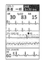
また、図5の最新表示モードでは、現時点の計測値「HR60 SpO294 RR19」、現時点までの心電図(図の例の場合、II誘導)、現在の日時(つまり最も新しく生体情報を計測した日時)「7/3 10:06:55」などが表示される。因みに、最新表示モード(図5)の心電図は、現時点に近い波形ほど下段側に表示される。また、最新表示モードでは、現時点からどれくらい前にアラームが発生したかが表示される(図の例の場合、「HR 1分20秒前」)。
Further, in the refresh mode shown in FIG. 5, the measured value of the current "HR60 SpO 2 94 RR19", electrocardiogram to date (in the example of FIG, II induction) was measured current date and time (i.e. most recently biological information Date ) "7/3 10:06:55" is displayed. Incidentally, the ECG in the latest display mode (FIG. 5) is displayed on the lower side as the waveform is closer to the present time. Also, in the latest display mode, how long before the alarm occurred from the present time is displayed (in the example of the figure, "HR 1
なお、図6に示したように、端末装置130が、図4のアラーム表示モードの画像と一緒に最新の心電図を表示するようにしてもよい。このようにすれば、アラームが発生したときの生体情報(心電図)と現時点の生体情報(心電図)とを同一画面上で比べることができるようになるので、ユーザーは患者の回復状態などを把握できるようになる。
As shown in FIG. 6, the
<3>アラームの確認履歴
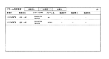
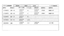
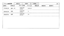
図7−図10は、確認履歴作成部113によって作成され、表示部114に表示されるアラーム確認履歴の例を示す図である。
<3> Alarm Confirmation History FIGS. 7 to 10 are diagrams illustrating examples of the alarm confirmation history created by the confirmation
図から分かるように、アラーム確認履歴には、患者ID、患者氏名、アラーム日時、アラーム名、確認日時、確認者ID、確認者名などが含まれる。 As can be seen from the figure, the alarm confirmation history includes a patient ID, a patient name, an alarm date and time, an alarm name, a confirmation date and time, a confirmer ID, a confirmer name, and the like.
ここで、アラーム日時とは、アラーム情報の発生日時を意味する。アラーム情報の発生日時とは、生体情報モニターによってアラームが形成された日時でもよいし上位サーバー110がアラーム情報を受信した日時でもよい。確認日時とは、上位サーバー110が端末装置130から応答信号を受信した日時である。換言すれば、確認履歴には、どの端末装置によってどのアラーム情報が確認されたかを示す情報が含まれている。アラーム日時と確認日時とを比較すれば、各アラーム情報がユーザーによって確認されたか否かを容易に知ることができる。
Here, the alarm date and time means the date and time when the alarm information is generated. The date and time of occurrence of the alarm information may be the date and time when the alarm is formed by the biological information monitor or the date and time when the
アラーム確認履歴の表示は、図7−図10のいずれかに切換可能となっている。具体的には、ユーザーが「確認済み」、「未確認」、「非通知」のボタンを選択することで表示を切り換えることができる。 The display of the alarm confirmation history can be switched to any one of FIGS. Specifically, the display can be switched by the user selecting the “confirmed”, “unconfirmed”, or “not notified” button.
図7は、確認済みリスト表示モードを示す。このモードでは、端末装置130によって確認されたアラーム情報のリストが表示される。ユーザーは、この表示に基づき、どのアラーム情報がどの端末装置によっていつ確認されたかを把握できる。
FIG. 7 shows the confirmed list display mode. In this mode, a list of alarm information confirmed by the
図8は、未確認リスト表示モードを示す。このモードでは、端末装置130によって確認されていないアラーム情報のリストが表示される。ユーザーは、この表示に基づき、どのアラーム情報が確認されていないかを把握できる。
FIG. 8 shows the unconfirmed list display mode. In this mode, a list of alarm information that has not been confirmed by the
図9は、確認済及び未確認リスト表示モードを示す。このモードでは、端末装置130によって確認されるべき全てのアラーム情報が表示される。ユーザーは、この表示に基づき、確認すべきアラームのうち、どれだけ確認されたかを把握できる。この場合、図のように、確認されていないアラームを着色するなどして、確認されていないアラームが目立つようにすると好ましい。
FIG. 9 shows the confirmed and unconfirmed list display modes. In this mode, all alarm information to be confirmed by the
図10は、非通知リスト表示モードを示す。このモードでは、生体情報モニターでは形成されたが、端末装置130には送信されなかったアラーム情報のリストが表示される。なお、勿論、生体情報モニターでは形成された全ての生体情報のリストを表示してもよい。
FIG. 10 shows the non-notification list display mode. In this mode, a list of alarm information formed on the biological information monitor but not transmitted to the
なお、図7−図10の例は、どの端末装置によってどのアラーム情報が確認されたかの確認履歴であるが、確認履歴作成部113は、これに加えて、どの端末装置によってどの生体情報が確認されたかを示す情報が含まれる確認履歴を作成してもよい。この確認履歴は、端末装置130から生体情報を確認したことを示す応答信号を受信することで作成できる。
Note that the example in FIGS. 7 to 10 is a confirmation history of which terminal device has confirmed which alarm information, and the confirmation
なお、図7−図10の例では、確認履歴が表形式となっているが、確認履歴は単なるログ情報であってもよい。表形式で表示する場合には、検索絞り込みや、ソートといった機能を付随させると好適である。 In the examples of FIGS. 7 to 10, the confirmation history is in a table format, but the confirmation history may be simple log information. When displaying in a table format, it is preferable to add functions such as search narrowing and sorting.
<4>まとめ
以上説明したように、本実施の形態によれば、生体情報管理システム100は、セントラルモニター10などの生体情報モニターから送信されたアラーム情報を受信して表示可能な端末装置130と、生体情報モニターから送信されたアラーム情報を記憶する記憶部111、端末装置130から送信された応答信号を受信する受信部(通信部112)、及び、記憶部111に記憶されたアラーム情報と応答信号との関係に基づいて端末装置130によるアラーム情報の確認履歴を作成する確認履歴作成部113を有する管理装置(上位サーバー110)と、を備えることにより、端末装置130のユーザーがアラーム情報を見たか否かの確認を管理者が容易かつ的確に知ることができるようになる。
<4> Summary As described above, according to the present embodiment, the biological
<5>他の実施の形態
上述の実施の形態は、本発明を実施するにあたっての具体化の一例を示したものに過ぎず、これらによって本発明の技術的範囲が限定的に解釈されてはならないものである。すなわち、本発明はその要旨、またはその主要な特徴から逸脱することの無い範囲で、様々な形で実施することができる。
<5> Other Embodiments The above-described embodiments are merely examples of embodiments for carrying out the present invention, and the technical scope of the present invention should not be interpreted in a limited manner. It must not be. That is, the present invention can be implemented in various forms without departing from the gist or the main features thereof.
<4−1>
上述の実施の形態では、端末装置130が他システム(ナースコールシステムや電子カルテシステム)120の外にある場合を例に説明したが、図11に示したように、端末装置130が他システム120に属する端末装置であってもよい。
<4-1>
In the above embodiment, the case where the
具体的には、端末装置130はナースコールシステムにおいて看護師が携帯する従来の携帯電話に代えて用いることができる。この場合の表示例について説明する。セントラルモニター10からアラーム発生情報が送信されると、このアラーム発生情報は直接あるいはナースコールシステムの通信部(図示せず)を介して端末装置130の通信部132で受信される。この結果、端末装置130の表示部131には図2に示したような画像が表示される。
Specifically, the
端末装置130のユーザーが図2の「確認」のボタンをタッチ操作すると、表示部131には図4に示したような画像が表示される。具体的には、図2の「確認」のボタンがタッチ操作されると、端末装置130は、上位サーバー110にアラーム発生情報、ユーザー情報(つまり端末装置130のIDや端末装置130を使用しているユーザーのID)を送信し、上位サーバー110はこれらの情報に対応する生体情報を記憶部111から読み出して端末装置130に送信し、端末装置130はこの生体情報及びアラーム情報に基づく画像を表示する。また、「確認」のボタンがタッチ操作されると、端末装置130は、上位サーバー110に応答信号を送信する。なお、端末装置130は、アラーム発生情報を受信したときに、図2の画像を表示せずに、図4の画像を表示するようにしてもよい。従来は図2の「確認」のボタンは看護師がアラームを見たときに操作するボタンとして利用されているが、上記の例ではこれに加えて生体情報を確認するためのボタンとして用いられている。勿論、「確認」のボタン以外に生体情報を表示させるための別の操作ボタンを設けてもよい。
When the user of the
端末装置130の表示処理は、電子カルテシステムのパソコンなどの端末装置の表示処理として用いることができる。この場合の表示例について説明する。電子カルテシステムのサーバーには、図3に示したようなアラーム着信履歴が記憶され、電子カルテシステムの端末装置130はこれを表示可能である。端末装置130のユーザーが図3の「HRアラーム」のボタンを操作すると、その端末装置130には図4に示したような画像が表示される。具体的には、図3の「HRアラーム」のボタンが操作されると、端末装置130は、上位サーバー110にそのボタンに対応したアラーム発生情報と、ユーザー情報(つまり端末装置130のIDや端末装置130を使用しているユーザーのID)とを送信し、上位サーバー110はこれらの情報に対応する生体情報を記憶部111から読み出して端末装置130に送信し、端末装置130はこの生体情報及びアラーム情報に基づく画像を表示する。勿論、図3に示したようなアラーム着信履歴の表示、及びここで述べたようなそれに基づく生体情報の読み出しと表示は、電子カルテシステムに限らずナースコールシステムで行うようにしてもよい。
The display process of the
<4−2>
上述の実施の形態では、生体情報モニターによって取得された患者のアラーム情報及び生体情報を記憶する記憶装置として上位サーバー110を例に挙げたが、記憶装置は上位サーバー110に限らない。要は、記憶装置は、生体情報モニターによって取得された生体情報を記憶しておき、この生体情報の中から、アラーム情報に対応する生体情報を読み出して送信できる構成であればよい。記憶装置は、アラーム情報に紐付けて生体情報を記憶している。
<4-2>
In the above-described embodiment, the
<4−3>
上述の実施の形態では、セントラルモニター10がアラーム発生情報(アラーム情報)を送信する場合について述べたが、本発明はこれに限らず、ベッドサイドモニター11やテレメーター送信機12がアラーム発生情報(アラーム情報)を送信してもよい。
<4-3>
In the above embodiment, the case where the
<4−4>
上述の実施の形態では、端末装置130が表示する生体情報が心電図である場合について述べたが、生体情報として心電図以外の波形を表示してもよい。また、複数の異なる波形を同時に表示してもよい。この場合、例えば異なる波形を1行ごとに交互に表示すると好ましい。また、図4及び図5の表示において、波形部をスクロールすることで、表示する範囲を選択可能としてもよい。
<4-4>
In the above-described embodiment, a case has been described where the biological information displayed by the
<4−5>
上述の実施の形態では、生体情報モニターから送信されたアラーム情報を記憶する記憶部111、端末装置から送信された応答信号を受信する受信部(通信部112)、及び、記憶部111に記憶されたアラーム情報と応答信号との関係に基づいて端末装置130によるアラーム情報の確認履歴を作成する確認履歴作成部113を有する管理装置を、上位サーバー110によって具現化した場合について述べたが、本発明はこれに限らず、本発明による管理装置は例えば他システム120内に設けられていてもよい。
<4-5>
In the above-described embodiment, the
上述の実施の形態では、上位サーバー110の表示部114にアラーム情報の確認履歴を表示した場合について述べたが、当該確認履歴は上位サーバー110以外で表示するようにしてもよい。例えば確認履歴作成部113によって作成した確認履歴を他システム120の表示部(図示せず)で表示するようにしてもよい。
In the above-described embodiment, the case where the confirmation history of the alarm information is displayed on the
本発明は、生体情報モニターから送られたアラーム情報を表示する端末装置を有する生体情報管理システムに適用し得る。 The present invention can be applied to a biological information management system having a terminal device that displays alarm information sent from a biological information monitor.
10 セントラルモニター
11 ベッドサイドモニター(BSモニター)
12 テレメーター送信機
20 生体情報モニタリングシステム
100 生体情報管理システム
110 上位サーバー
111 記憶部
112、132 通信部
113 確認履歴作成部
114、131 表示部
120 他システム
130 端末装置
10 Central monitor 11 Bedside monitor (BS monitor)
Claims (14)
前記生体情報モニターから送信された前記アラーム情報を記憶する記憶部と、前記端末装置から送信された応答信号を受信する受信部と、前記記憶部に記憶されたアラーム情報と前記応答信号との関係に基づいて前記端末装置による前記アラーム情報の確認履歴を作成する確認履歴作成部とを有する管理装置と、
を具備する生体情報管理システム。 A terminal device capable of receiving and displaying the alarm information transmitted from the biological information monitor,
A storage unit that stores the alarm information transmitted from the biological information monitor, a receiving unit that receives a response signal transmitted from the terminal device, and a relationship between the alarm information stored in the storage unit and the response signal A management device having a confirmation history creating unit that creates a confirmation history of the alarm information by the terminal device based on
A biological information management system comprising:
請求項1に記載の生体情報管理システム。 The confirmation history includes information indicating which alarm information has been confirmed by which terminal device,
The biological information management system according to claim 1.
前記確認履歴作成部は、さらに、前記記憶部に記憶された生体情報と前記応答信号との関係に基づいて前記端末装置による前記生体情報の確認履歴を作成する、
請求項1又は2に記載の生体情報管理システム。 The storage unit further stores the biological information transmitted from the biological information monitor,
The confirmation history creation unit further creates a confirmation history of the biological information by the terminal device based on a relationship between the biological information and the response signal stored in the storage unit,
The biological information management system according to claim 1.
請求項3に記載の生体情報管理システム。 The confirmation history includes information indicating which biological information has been confirmed by which terminal device,
The biological information management system according to claim 3.
請求項1から4のいずれか一項に記載の生体情報管理システム。 The confirmation history includes a table indicating the correspondence between the date and time of occurrence of the alarm information and the date and time at which the alarm information was confirmed,
The biological information management system according to claim 1.
前記確認履歴作成部は、前記確認履歴として、前記端末装置に送信されたアラーム情報についての確認履歴を作成する、
請求項1又は2に記載の生体情報管理システム。 The alarm information stored in the storage unit includes alarm information transmitted to the terminal device and alarm information not transmitted to the terminal device,
The confirmation history creation unit, as the confirmation history, creates a confirmation history for the alarm information transmitted to the terminal device,
The biological information management system according to claim 1.
前記生体情報モニターから送信された前記アラーム情報を記憶する記憶部と、
前記端末装置から送信された応答信号を受信する受信部と、
前記記憶部に記憶されたアラーム情報と前記応答信号との関係に基づいて、前記端末装置による前記アラーム情報の確認履歴を作成する確認履歴作成部と、
を具備する管理装置。 A management device in a system that transmits alarm information of a biological information monitor to a terminal device,
A storage unit that stores the alarm information transmitted from the biological information monitor,
A receiving unit that receives a response signal transmitted from the terminal device,
A confirmation history creation unit that creates a confirmation history of the alarm information by the terminal device based on a relationship between the alarm information and the response signal stored in the storage unit;
A management device comprising:
前記確認履歴作成部は、さらに、前記記憶部に記憶された生体情報と前記応答信号との関係に基づいて前記端末装置による前記生体情報の確認履歴を作成する、
請求項7に記載の管理装置。 The storage unit further stores the biological information transmitted from the biological information monitor,
The confirmation history creation unit further creates a confirmation history of the biological information by the terminal device based on a relationship between the biological information and the response signal stored in the storage unit,
The management device according to claim 7.
前記確認履歴作成部は、前記確認履歴として、前記端末装置に送信されたアラーム情報についての確認履歴を作成する、
請求項7又は8に記載の管理装置。 The alarm information stored in the storage unit includes alarm information transmitted to the terminal device and alarm information not transmitted to the terminal device,
The confirmation history creation unit, as the confirmation history, creates a confirmation history for the alarm information transmitted to the terminal device,
The management device according to claim 7.
前記生体情報モニターから送信された前記アラーム情報を記憶する記憶ステップと、
前記端末装置から送信された応答信号を受信する受信ステップと、
前記記憶ステップで記憶したアラーム情報と前記応答信号との関係に基づいて、前記端末装置による前記アラーム情報の確認履歴を作成する確認履歴作成ステップと、
前記確認履歴を表示する表示ステップと、
を含む表示方法。 A display method in a system for transmitting alarm information of a biological information monitor to a terminal device,
A storage step of storing the alarm information transmitted from the biological information monitor,
A receiving step of receiving a response signal transmitted from the terminal device,
A confirmation history creation step of creating a confirmation history of the alarm information by the terminal device based on a relationship between the alarm information and the response signal stored in the storage step;
A display step of displaying the confirmation history;
Display method including.
どの端末装置によってどのアラーム情報が確認されたかを示す情報が含まれる、
請求項10に記載の表示方法。 In the displaying step,
Information indicating which alarm information has been acknowledged by which terminal device;
The display method according to claim 10.
前記端末装置によって確認されたアラーム情報のリストが表示される、
請求項10に記載の表示方法。 In the displaying step,
A list of alarm information confirmed by the terminal device is displayed.
The display method according to claim 10.
前記端末装置によって確認されていないアラーム情報のリストが表示される、
請求項10に記載の表示方法。 In the displaying step,
A list of alarm information not confirmed by the terminal device is displayed,
The display method according to claim 10.
前記端末装置によって確認されたアラーム情報のリストと、前記端末装置によって確認されていないアラーム情報のリストと、が表示される、
請求項10に記載の表示方法。 In the displaying step,
A list of alarm information confirmed by the terminal device and a list of alarm information not confirmed by the terminal device are displayed.
The display method according to claim 10.
Priority Applications (1)
| Application Number | Priority Date | Filing Date | Title |
|---|---|---|---|
| JP2018165101A JP7179540B2 (en) | 2018-09-04 | 2018-09-04 | Biological information management system, management device and display method |
Applications Claiming Priority (1)
| Application Number | Priority Date | Filing Date | Title |
|---|---|---|---|
| JP2018165101A JP7179540B2 (en) | 2018-09-04 | 2018-09-04 | Biological information management system, management device and display method |
Publications (2)
| Publication Number | Publication Date |
|---|---|
| JP2020036734A true JP2020036734A (en) | 2020-03-12 |
| JP7179540B2 JP7179540B2 (en) | 2022-11-29 |
Family
ID=69737019
Family Applications (1)
| Application Number | Title | Priority Date | Filing Date |
|---|---|---|---|
| JP2018165101A Active JP7179540B2 (en) | 2018-09-04 | 2018-09-04 | Biological information management system, management device and display method |
Country Status (1)
| Country | Link |
|---|---|
| JP (1) | JP7179540B2 (en) |
Citations (2)
| Publication number | Priority date | Publication date | Assignee | Title |
|---|---|---|---|---|
| JP2006180979A (en) * | 2004-12-27 | 2006-07-13 | Nippon Koden Corp | Multiple patient alarm information display method and apparatus |
| JP2017018379A (en) * | 2015-07-10 | 2017-01-26 | パラマウントベッド株式会社 | Patient status reporting device, reporting method and program in patient status reporting device |
-
2018
- 2018-09-04 JP JP2018165101A patent/JP7179540B2/en active Active
Patent Citations (2)
| Publication number | Priority date | Publication date | Assignee | Title |
|---|---|---|---|---|
| JP2006180979A (en) * | 2004-12-27 | 2006-07-13 | Nippon Koden Corp | Multiple patient alarm information display method and apparatus |
| JP2017018379A (en) * | 2015-07-10 | 2017-01-26 | パラマウントベッド株式会社 | Patient status reporting device, reporting method and program in patient status reporting device |
Also Published As
| Publication number | Publication date |
|---|---|
| JP7179540B2 (en) | 2022-11-29 |
Similar Documents
| Publication | Publication Date | Title |
|---|---|---|
| US8310336B2 (en) | Systems and methods for storing, analyzing, retrieving and displaying streaming medical data | |
| KR20220083771A (en) | Display layouts and interactive objects for patient monitoring | |
| US20160125151A1 (en) | Physiological Parameter Measuring Platform Device Supporting Multiple Workflows | |
| US20150119733A1 (en) | System and Method of Evaluating an Association Between a Wireless Sensor and a Monitored Patient | |
| EP3189774B1 (en) | Medical sensor as well as using method therefor and operating device thereof | |
| JP6243651B2 (en) | Critical call system and biological information monitor | |
| JP2023120424A (en) | Biological information management system and terminal device | |
| JP2005095469A (en) | Biological monitor information registration / display system | |
| JP2021119989A (en) | Display device | |
| JP2006180979A (en) | Multiple patient alarm information display method and apparatus | |
| US12303300B2 (en) | Terminal device, information providing system, and computer program | |
| US8976032B2 (en) | Systems, methods and computer-readable media for identifying an anonymous patient | |
| JP7179540B2 (en) | Biological information management system, management device and display method | |
| JP7339005B2 (en) | Biological information monitoring system | |
| KR20100095780A (en) | The patient management system for hospital | |
| JP6738715B2 (en) | Terminal device, information providing method, and computer program | |
| CN102525425B (en) | Physiological information identification device and physiological information identifying method | |
| JP2019013682A (en) | Bedside monitor | |
| JP2006072828A (en) | Medical information system | |
| KR20180067331A (en) | System for managing patient in emergency using wearable devices | |
| JP7106253B2 (en) | Bedside monitor and vital information monitoring system | |
| JP5560399B2 (en) | ECG information communication system operation monitoring system | |
| JP2016186771A (en) | Health management system | |
| JP6744200B2 (en) | Information providing system and information providing method | |
| CN111163429A (en) | Nurse bracelet connected system based on Lora communication |
Legal Events
| Date | Code | Title | Description |
|---|---|---|---|
| A521 | Request for written amendment filed |
Free format text: JAPANESE INTERMEDIATE CODE: A523 Effective date: 20180914 |
|
| RD02 | Notification of acceptance of power of attorney |
Free format text: JAPANESE INTERMEDIATE CODE: A7422 Effective date: 20190704 |
|
| RD04 | Notification of resignation of power of attorney |
Free format text: JAPANESE INTERMEDIATE CODE: A7424 Effective date: 20191107 |
|
| A621 | Written request for application examination |
Free format text: JAPANESE INTERMEDIATE CODE: A621 Effective date: 20210902 |
|
| A977 | Report on retrieval |
Free format text: JAPANESE INTERMEDIATE CODE: A971007 Effective date: 20220622 |
|
| A131 | Notification of reasons for refusal |
Free format text: JAPANESE INTERMEDIATE CODE: A131 Effective date: 20220726 |
|
| A521 | Request for written amendment filed |
Free format text: JAPANESE INTERMEDIATE CODE: A523 Effective date: 20220922 |
|
| TRDD | Decision of grant or rejection written | ||
| A01 | Written decision to grant a patent or to grant a registration (utility model) |
Free format text: JAPANESE INTERMEDIATE CODE: A01 Effective date: 20221018 |
|
| A61 | First payment of annual fees (during grant procedure) |
Free format text: JAPANESE INTERMEDIATE CODE: A61 Effective date: 20221116 |
|
| R150 | Certificate of patent or registration of utility model |
Ref document number: 7179540 Country of ref document: JP Free format text: JAPANESE INTERMEDIATE CODE: R150 |
|
| R250 | Receipt of annual fees |
Free format text: JAPANESE INTERMEDIATE CODE: R250 |