JP2020036419A - Emergency lighting fixture - Google Patents

Emergency lighting fixture Download PDF

Info

Publication number
JP2020036419A
JP2020036419A JP2018159635A JP2018159635A JP2020036419A JP 2020036419 A JP2020036419 A JP 2020036419A JP 2018159635 A JP2018159635 A JP 2018159635A JP 2018159635 A JP2018159635 A JP 2018159635A JP 2020036419 A JP2020036419 A JP 2020036419A
Authority
JP
Japan
Prior art keywords
circuit
power supply
emergency lighting
voltage
control unit
Prior art date
Legal status (The legal status is an assumption and is not a legal conclusion. Google has not performed a legal analysis and makes no representation as to the accuracy of the status listed.)
Pending
Application number
JP2018159635A
Other languages
Japanese (ja)
Inventor
明穂 相場
Akiho Aiba
明穂 相場
安雄 松本
Yasuo Matsumoto
安雄 松本
雄也 平本
Yuya Hiramoto
雄也 平本
Current Assignee (The listed assignees may be inaccurate. Google has not performed a legal analysis and makes no representation or warranty as to the accuracy of the list.)
Mitsubishi Electric Corp
Original Assignee
Mitsubishi Electric Corp
Priority date (The priority date is an assumption and is not a legal conclusion. Google has not performed a legal analysis and makes no representation as to the accuracy of the date listed.)
Filing date
Publication date
Application filed by Mitsubishi Electric Corp filed Critical Mitsubishi Electric Corp
Priority to JP2018159635A priority Critical patent/JP2020036419A/en
Publication of JP2020036419A publication Critical patent/JP2020036419A/en
Pending legal-status Critical Current

Links

Images

Abstract

To provide an emergency lighting fixture capable of reducing manufacturing costs.SOLUTION: The emergency lighting fixture includes: a light source; a battery; a regular power supply circuit supplied with power from an external power supply so as to charge the battery; an emergency lighting circuit for boosting an output voltage of the battery so as to light the light source; and a control unit for controlling the emergency lighting circuit. The output voltage of the battery is lower than an operating voltage of the control unit. The control unit is operated by being supplied with power from the regular power supply circuit or the emergency lighting circuit, and, when a power failure of the external power supply is detected, the emergency lighting circuit is operated.SELECTED DRAWING: Figure 1

Description

本発明は、非常用照明装置に関する。   The present invention relates to an emergency lighting device.

特許文献1には、乾電池を直流電源として用いて、制御ICの制御用電源に直流電源より高い電圧を供給するDC/DCコンバータが開示されている。このDC/DCコンバータでは、制御ICの制御用電源として、変圧回路により昇圧された出力を利用して、直流電源の電圧より高い電圧を供給できる定電圧回路が用いられている。   Patent Document 1 discloses a DC / DC converter that uses a dry battery as a DC power supply and supplies a higher voltage than the DC power supply to a control power supply of a control IC. In this DC / DC converter, a constant voltage circuit capable of supplying a voltage higher than the voltage of the DC power supply by using the output boosted by the transformer circuit is used as a control power supply for the control IC.

特開2003−111390号公報JP 2003-111390 A

例えば不特定多数の人が集まる場所での火災、地震等の災害または事故の際に生じる停電時には、その場にいる人々が安全に避難できるように、室内を照明する非常灯が用いられることがある。非常灯の光源としては、一般に蛍光ランプまたはLEDが採用される。   For example, in the event of a disaster or accident such as a fire or earthquake at a place where an unspecified number of people gather, emergency lights that illuminate the interior of the room may be used so that people at the place can safely evacuate. is there. As a light source of the emergency light, a fluorescent lamp or an LED is generally employed.

一般に、LEDを用いた照明装置は、従来のような蛍光ランプを用いた照明装置よりも変換効率が高い。このため、電池を小型化することで照明装置の小型化が図られる場合がある。このとき、電池のセル数が削減されることがある。   Generally, a lighting device using an LED has higher conversion efficiency than a lighting device using a conventional fluorescent lamp. Therefore, the size of the lighting device may be reduced by reducing the size of the battery. At this time, the number of cells of the battery may be reduced.

非常灯の制御用ICの電源電圧として、電池電圧よりも高い電圧を必要とする場合を考える。特許文献1では、制御用ICの電源を定電圧回路により昇圧された側から供給している。しかしながら、一般に非常灯では最低限の明るさが決められている。このため、非常用点灯回路は定電流型または定電力型であることが求められ、定電圧型では実現が難しい場合がある。従って、特許文献1を非常灯に適用すると、LEDを点灯させるための点灯回路とは別に、制御用ICの電源を生成するための定電圧回路が設けられることとなる。このため、非常灯のコストアップまたは大型化に繋がる恐れがある。   Consider a case where a voltage higher than the battery voltage is required as the power supply voltage of the emergency light control IC. In Patent Literature 1, power for a control IC is supplied from the side boosted by a constant voltage circuit. However, an emergency light generally has a minimum brightness. For this reason, the emergency lighting circuit is required to be a constant current type or a constant power type, and it may be difficult to realize the emergency lighting circuit with a constant voltage type. Therefore, when Patent Document 1 is applied to an emergency light, a constant voltage circuit for generating a power supply for the control IC is provided separately from a lighting circuit for lighting an LED. This may lead to an increase in the cost or size of the emergency light.

本発明は、上述の課題を解決するためになされたもので、製造コストを低減できる非常用照明装置を得ることを目的とする。   The present invention has been made in order to solve the above-mentioned problem, and an object of the present invention is to provide an emergency lighting device capable of reducing manufacturing costs.

本発明に係る非常用照明装置は、光源と、電池と、外部電源から電力を供給され、該電池を充電する常用電源回路と、該電池の出力電圧を昇圧し、該光源を点灯させる非常用点灯回路と、該非常用点灯回路を制御する制御部と、を備え、該電池の該出力電圧は、該制御部の動作電圧より低く、該制御部は、該常用電源回路または該非常用点灯回路から電力を供給され動作し、該外部電源の停電を検出すると該非常用点灯回路を動作させる。   An emergency lighting device according to the present invention includes a light source, a battery, a power supply circuit that is supplied with power from an external power supply and charges the battery, and an emergency light source that boosts an output voltage of the battery and turns on the light source. A lighting circuit, and a control unit for controlling the emergency lighting circuit, wherein the output voltage of the battery is lower than an operating voltage of the control unit, and the control unit is configured to control the emergency power supply circuit or the emergency lighting circuit. The emergency lighting circuit is operated by being supplied with power from the circuit and operating when the power failure of the external power supply is detected.

本発明に係る非常用照明装置では、制御部は常用電源回路または非常用点灯回路から電力を供給され動作する。常用時には常用電源回路が動作しているため、制御部は常用電源回路から電力を供給される。停電時には、制御部は非常用点灯回路を動作させる。これにより、制御部は非常用点灯回路から電力を供給される。このため、制御部の電源を生成するための昇圧回路を設けなくても良い。従って、製造コストを低減できる。   In the emergency lighting device according to the present invention, the control unit operates by being supplied with electric power from the normal power supply circuit or the emergency lighting circuit. The control unit is supplied with power from the normal power supply circuit because the normal power supply circuit is operating during normal use. At the time of power failure, the control unit operates the emergency lighting circuit. Thus, the control unit is supplied with power from the emergency lighting circuit. Therefore, it is not necessary to provide a booster circuit for generating a power supply for the control unit. Therefore, manufacturing costs can be reduced.

実施の形態1に係る非常用照明装置の回路ブロック図である。FIG. 2 is a circuit block diagram of the emergency lighting device according to the first embodiment. 実施の形態1に係る常用電源回路と非常用点灯回路の電圧波形を示す図である。FIG. 3 is a diagram illustrating voltage waveforms of a normal power supply circuit and an emergency lighting circuit according to the first embodiment. 実施の形態1に係る入力電圧検出回路の電圧波形を示す図である。FIG. 3 is a diagram illustrating a voltage waveform of the input voltage detection circuit according to the first embodiment.

本発明の実施の形態に係る非常用照明装置について図面を参照して説明する。同じ又は対応する構成要素には同じ符号を付し、説明の繰り返しを省略する場合がある。   An emergency lighting device according to an embodiment of the present invention will be described with reference to the drawings. The same or corresponding components are denoted by the same reference numerals, and description thereof may not be repeated.

実施の形態1.
図1は、実施の形態1に係る非常用照明装置100の回路ブロック図である。非常用照明装置100は、LED30と、ユニット10と、電池250を備える。LED30は、非常時に明るさを確保するための光源である。ユニット10は外部電源ACからの給電を受け、電池250を充電する。外部電源ACは交流電源である。電池250は非常時にLED30に給電を行う。
Embodiment 1 FIG.
FIG. 1 is a circuit block diagram of the emergency lighting device 100 according to the first embodiment. The emergency lighting device 100 includes the LED 30, the unit 10, and the battery 250. The LED 30 is a light source for ensuring brightness in an emergency. The unit 10 receives power from an external power supply AC and charges the battery 250. The external power supply AC is an AC power supply. The battery 250 supplies power to the LED 30 in an emergency.

ユニット10は、入力フィルタ回路1と、常用電源回路2と、非常用点灯回路3と、電源生成回路4と、制御回路5を備える。   The unit 10 includes an input filter circuit 1, a regular power supply circuit 2, an emergency lighting circuit 3, a power supply generation circuit 4, and a control circuit 5.

入力フィルタ回路1は、過電流を保護するためのヒューズ11と、交流用のコンデンサ12と、交流を直流に変換するためのダイオードブリッジ13を備えている。外部電源ACの高電位側には、ヒューズ11の一端が接続される。ヒューズ11の他端はコンデンサ12の正極とダイオードブリッジ13の入力の高電位側に接続される。コンデンサ12の負極は外部電源ACの低電位側とダイオードブリッジ13の入力の低電位側に接続される。ダイオードブリッジ13の出力は常用電源回路2に接続される。   The input filter circuit 1 includes a fuse 11 for protecting overcurrent, a capacitor 12 for AC, and a diode bridge 13 for converting AC to DC. One end of the fuse 11 is connected to the high potential side of the external power supply AC. The other end of the fuse 11 is connected to the positive electrode of the capacitor 12 and the high potential side of the input of the diode bridge 13. The negative electrode of the capacitor 12 is connected to the low potential side of the external power supply AC and the low potential side of the input of the diode bridge 13. The output of the diode bridge 13 is connected to the ordinary power supply circuit 2.

常用電源回路2は、絶縁形フライバック回路から構成される。常用電源回路2は、常用時に外部電源ACから電力を供給され、電池250を充電する。また、マイコン50は常用電源回路2を制御する。ここで常用時とは、外部電源ACが停電状態または疑似停電状態では無い通常の状態を示す。   The service power supply circuit 2 is configured by an insulated flyback circuit. The power supply circuit 2 is supplied with power from an external power supply AC during normal use, and charges the battery 250. Further, the microcomputer 50 controls the ordinary power supply circuit 2. Here, the normal time indicates a normal state in which the external power supply AC is not in the power failure state or the pseudo power failure state.

常用電源回路2において、ダイオードブリッジ13の出力と並列にコンデンサ201が接続される。ダイオードブリッジ13の出力の低電位側は接地用端子に接続される。コンデンサ201の正極には、コンデンサ202の正極、抵抗203の一端およびトランス220の一次側の一端が接続される。コンデンサ202の負極と抵抗203の他端にはダイオード204のカソードが接続される。コンデンサ202、抵抗203およびダイオード204は、スイッチングに伴う過渡的な高電圧を吸収するスナバ回路を形成する。   In the service power supply circuit 2, a capacitor 201 is connected in parallel with the output of the diode bridge 13. The low potential side of the output of the diode bridge 13 is connected to a ground terminal. The positive electrode of the capacitor 201 is connected to the positive electrode of the capacitor 202, one end of the resistor 203, and one end of the transformer 220 on the primary side. The cathode of a diode 204 is connected to the negative electrode of the capacitor 202 and the other end of the resistor 203. The capacitor 202, the resistor 203, and the diode 204 form a snubber circuit that absorbs a transient high voltage accompanying switching.

ダイオード204のアノードには、スイッチング素子205の第1端子とトランス220の一次側の他端が接続される。スイッチング素子205は、トランス220の一次巻き線と直列に接続される。スイッチング素子205の第2端子はコンデンサ201の負極に接続される。スイッチング素子205の制御端子は、制御IC200に接続されている。制御端子は、第1、第2端子間をスイッチングするための端子である。   The first terminal of the switching element 205 and the other end of the primary side of the transformer 220 are connected to the anode of the diode 204. Switching element 205 is connected in series with the primary winding of transformer 220. The second terminal of the switching element 205 is connected to the negative electrode of the capacitor 201. The control terminal of the switching element 205 is connected to the control IC 200. The control terminal is a terminal for switching between the first and second terminals.

スイッチング素子205は、例えばMOSFET(Metal−Oxide−Semiconductor Field−Effect Transistor)である。スイッチング素子205がMOSFETの場合、第1端子はドレイン端子、第2端子はソース端子、制御端子はゲート端子である。スイッチング素子205において、第1端子がトランス220、第2端子が接地用端子、第3端子が制御IC200に接続される。   The switching element 205 is, for example, a MOSFET (Metal-Oxide-Semiconductor Field-Effect Transistor). When the switching element 205 is a MOSFET, the first terminal is a drain terminal, the second terminal is a source terminal, and the control terminal is a gate terminal. In the switching element 205, the first terminal is connected to the transformer 220, the second terminal is connected to the ground terminal, and the third terminal is connected to the control IC 200.

制御IC200はPFC(Power Factor Correction)ドライバである。制御IC200はスイッチング素子205を駆動させる。トランス220の一次側の補助巻き線にはダイオード208のアノードが接続される。ダイオード208のカソードは、制御IC200の電源端子Vcc1に接続される。ダイオード208は、制御IC200の電源をトランス220の補助巻き線から供給する。   The control IC 200 is a PFC (Power Factor Correction) driver. The control IC 200 drives the switching element 205. The anode of the diode 208 is connected to the auxiliary winding on the primary side of the transformer 220. The cathode of diode 208 is connected to power supply terminal Vcc1 of control IC 200. The diode 208 supplies power for the control IC 200 from the auxiliary winding of the transformer 220.

制御IC200には抵抗206を介してフォトカプラ207が接続される。抵抗206、フォトカプラ207は、トランス220の二次側の情報を制御IC200に入力するために設けられる。   A photocoupler 207 is connected to the control IC 200 via a resistor 206. The resistor 206 and the photocoupler 207 are provided to input information on the secondary side of the transformer 220 to the control IC 200.

トランス220の二次側のフライバック巻き線の一端には、ダイオード209のアノードが接続される。ダイオード209は、トランス220の二次側に直列に接続され、出力側に安定した電圧を伝達するために設けられる。ダイオード209のカソードには、電解コンデンサ214の正極が接続される。電解コンデンサ214の負極は接地用端子に接続される。   The anode of the diode 209 is connected to one end of the flyback winding on the secondary side of the transformer 220. The diode 209 is connected in series to the secondary side of the transformer 220, and is provided for transmitting a stable voltage to the output side. The cathode of diode 209 is connected to the positive electrode of electrolytic capacitor 214. The negative electrode of the electrolytic capacitor 214 is connected to a ground terminal.

電解コンデンサ214の正極には抵抗217を介して電池250の一端が接続される。電池250の他端は電解コンデンサ214の負極に接続される。抵抗217は、電池250と直列に接続され、電池250の電流を制限するために設けられる。   One end of a battery 250 is connected to the positive electrode of the electrolytic capacitor 214 via a resistor 217. The other end of battery 250 is connected to the negative electrode of electrolytic capacitor 214. The resistor 217 is connected in series with the battery 250, and is provided to limit the current of the battery 250.

常用電源回路2は出力電圧検出回路を備える。出力電圧検出回路は、直列に接続された抵抗215と抵抗216から構成される。出力電圧検出回路は、電解コンデンサ214と並列に接続される。抵抗215と抵抗216の分圧値は、制御部であるマイコン50に入力される。これにより、マイコン50は常用電源回路2の出力電圧を検出する。   The service power supply circuit 2 includes an output voltage detection circuit. The output voltage detection circuit includes a resistor 215 and a resistor 216 connected in series. The output voltage detection circuit is connected in parallel with the electrolytic capacitor 214. The divided voltage values of the resistors 215 and 216 are input to the microcomputer 50 as a control unit. Thereby, the microcomputer 50 detects the output voltage of the service power supply circuit 2.

電池250と並列に抵抗218と抵抗219の直列回路が接続される。抵抗218、219で電池電圧を分圧した電圧は、マイコン50に入力される。マイコン50は、出力電圧検出回路で検出した常用電源回路2の出力電圧と、抵抗218、219で電池電圧を分圧した電圧との電圧差を算出する。マイコン50は、算出した電圧差と、抵抗217の抵抗値とを用いて演算を行い、スイッチング素子205をオンオフする信号の目標値を算出する。   A series circuit of resistors 218 and 219 is connected in parallel with the battery 250. The voltage obtained by dividing the battery voltage by the resistors 218 and 219 is input to the microcomputer 50. The microcomputer 50 calculates a voltage difference between the output voltage of the service power supply circuit 2 detected by the output voltage detection circuit and the voltage obtained by dividing the battery voltage by the resistors 218 and 219. The microcomputer 50 performs an operation using the calculated voltage difference and the resistance value of the resistor 217 to calculate a target value of a signal for turning on and off the switching element 205.

マイコン50は、算出した目標値に沿った矩形波を出力端子から出力する。マイコン50の出力端子には抵抗55、57を介してフォトカプラ58が接続される。また、抵抗57とフォトカプラ58が形成する直列回路の並列にコンデンサ56が接続される。マイコン50が出力する矩形波は、抵抗55とコンデンサ56で平均化される。この電圧は、抵抗57、フォトカプラ58を介してトランス220の一次側に設けられたフォトカプラ207に伝達される。   The microcomputer 50 outputs a rectangular wave according to the calculated target value from an output terminal. An output terminal of the microcomputer 50 is connected to a photocoupler 58 via resistors 55 and 57. Further, a capacitor 56 is connected in parallel with a series circuit formed by the resistor 57 and the photocoupler 58. The rectangular wave output from the microcomputer 50 is averaged by the resistor 55 and the capacitor 56. This voltage is transmitted to the photocoupler 207 provided on the primary side of the transformer 220 via the resistor 57 and the photocoupler 58.

これにより、マイコン50の出力信号は、フォトカプラ207、抵抗206、制御IC200を介してスイッチング素子205をオンオフする。以上から、絶縁形フライバック回路の定電流フィードバックが実現される。常用電源回路2は、二次側に接続される電池250を定電流で充電する。   Thus, the output signal of the microcomputer 50 turns the switching element 205 on and off via the photocoupler 207, the resistor 206, and the control IC 200. As described above, constant current feedback of the insulated flyback circuit is realized. The regular power supply circuit 2 charges the battery 250 connected to the secondary side with a constant current.

常用電源回路2は入力電圧検出回路240を備える。入力電圧検出回路240は、トランス220の二次側に直列に接続され、常用電源回路2への入力電圧を検出する。入力電圧検出回路240は、第1抵抗212と第2抵抗213から形成される直列回路を有する。また、入力電圧検出回路240は、トランス220の二次側のフォワード巻き線の一端に接続されたダイオード210を備える。   The service power supply circuit 2 includes an input voltage detection circuit 240. The input voltage detection circuit 240 is connected in series to the secondary side of the transformer 220 and detects an input voltage to the service power supply circuit 2. The input voltage detection circuit 240 has a series circuit formed by the first resistor 212 and the second resistor 213. The input voltage detection circuit 240 includes a diode 210 connected to one end of a forward winding on the secondary side of the transformer 220.

ダイオード210は、アノードがトランス220の二次側に接続され、カソードが第1抵抗212と第2抵抗213から形成される直列回路の一端に接続される。この直列回路の他端は、接地用端子に接続される。第1抵抗212と第2抵抗213から形成される直列回路と並列に、平滑用のコンデンサ211が接続される。第1抵抗212と第2抵抗213で分圧した電圧はマイコン50に入力される。これにより、マイコン50は、常用電源回路2への入力電圧を検出する。   The diode 210 has an anode connected to the secondary side of the transformer 220 and a cathode connected to one end of a series circuit formed by the first resistor 212 and the second resistor 213. The other end of the series circuit is connected to a ground terminal. A smoothing capacitor 211 is connected in parallel with a series circuit formed by the first resistor 212 and the second resistor 213. The voltage divided by the first resistor 212 and the second resistor 213 is input to the microcomputer 50. Thereby, the microcomputer 50 detects the input voltage to the service power supply circuit 2.

非常用点灯回路3は、昇圧型スイッチング回路で構成されている。非常用点灯回路3は、外部電源ACの停電時または疑似停電時等の非常時に、電池250の出力電圧を昇圧してLED30を点灯させる。   The emergency lighting circuit 3 is configured by a boost type switching circuit. The emergency lighting circuit 3 boosts the output voltage of the battery 250 and lights the LED 30 in an emergency such as a power failure of the external power supply AC or a pseudo power failure.

非常用点灯回路3の入力端にはコンデンサ31が並列に接続される。コンデンサ31の正極には、電池250の一端とコイル32の一端が接続される。コンデンサ31の負極は接地用端子に接続される。コイル32の他端は、ダイオード34のアノードに接続される。ダイオード34のカソードは、コンデンサ35の正極に接続される。コンデンサ35の負極は、コンデンサ31の負極に接続される。つまり、コンデンサ31と並列に、コイル32、ダイオード34、コンデンサ35の順で接続された直列回路が接続されている。   A capacitor 31 is connected in parallel to the input terminal of the emergency lighting circuit 3. One end of the battery 250 and one end of the coil 32 are connected to the positive electrode of the capacitor 31. The negative electrode of the capacitor 31 is connected to a ground terminal. The other end of the coil 32 is connected to the anode of the diode 34. The cathode of the diode 34 is connected to the positive electrode of the capacitor 35. The negative electrode of the capacitor 35 is connected to the negative electrode of the capacitor 31. That is, a series circuit connected in the order of the coil 32, the diode 34, and the capacitor 35 is connected in parallel with the capacitor 31.

コイル32とダイオード34の接続点と接地用端子との間には、スイッチング素子33が接続されている。スイッチング素子33の第1端子は、ダイオード34のアノードに接続される。スイッチング素子33の第2端子はコンデンサ31の負極に接続される。スイッチング素子33の制御端子は、マイコン50に接続される。スイッチング素子33は、例えばMOSFETである。   A switching element 33 is connected between a connection point between the coil 32 and the diode 34 and a ground terminal. The first terminal of the switching element 33 is connected to the anode of the diode 34. The second terminal of the switching element 33 is connected to the negative electrode of the capacitor 31. The control terminal of the switching element 33 is connected to the microcomputer 50. The switching element 33 is, for example, a MOSFET.

コンデンサ35の正極には、LED30のアノード側が接続される。LED30のカソード側にはセンス抵抗38の一端が接続される。センス抵抗38の他端はコンデンサ35の負極に接続される。図1では、LED30が一つ示されているが、非常用照明装置100が備えるLED30の数は1つ以上であれば良い。   The anode side of the LED 30 is connected to the positive electrode of the capacitor 35. One end of a sense resistor 38 is connected to the cathode side of the LED 30. The other end of the sense resistor 38 is connected to the negative electrode of the capacitor 35. Although one LED 30 is shown in FIG. 1, the number of LEDs 30 included in the emergency lighting device 100 may be one or more.

非常用点灯回路3は出力電圧検出回路を備える。出力電圧検出回路は、直列に接続された抵抗36と抵抗37から構成される。出力電圧検出回路は、コンデンサ35と並列に接続される。抵抗36と抵抗37の分圧値はマイコン50に入力される。これにより、マイコン50は非常用点灯回路3の出力電圧を検出する。   The emergency lighting circuit 3 includes an output voltage detection circuit. The output voltage detection circuit includes a resistor 36 and a resistor 37 connected in series. The output voltage detection circuit is connected in parallel with the capacitor 35. The divided voltage values of the resistors 36 and 37 are input to the microcomputer 50. Thereby, the microcomputer 50 detects the output voltage of the emergency lighting circuit 3.

センス抵抗38の一端は、マイコン50に接続される。センス抵抗38には、LED30を流れる電流に対応する電圧が印加される。マイコン50には、センス抵抗38に印加される電圧が入力される。マイコン50は、センス抵抗38により検出された電圧と予め定められた目標値との比較を行う。マイコン50は、センス抵抗38による検出電圧と目標値を一致させるように、スイッチング素子33の第3端子に信号を出力する。   One end of the sense resistor 38 is connected to the microcomputer 50. A voltage corresponding to the current flowing through the LED 30 is applied to the sense resistor 38. The voltage applied to the sense resistor 38 is input to the microcomputer 50. The microcomputer 50 compares the voltage detected by the sense resistor 38 with a predetermined target value. The microcomputer 50 outputs a signal to the third terminal of the switching element 33 so that the voltage detected by the sense resistor 38 matches the target value.

スイッチング素子33は、マイコン50からの出力信号に応じてスイッチングする。これにより、LED30に流れる電流を目標値と一致させることができる。従って、昇圧型スイッチング回路の定電流フィードバックが実現する。このように、マイコン50は非常用点灯回路3を制御する。また、非常用点灯回路3が定電力制御型の場合は、定電圧制御と定電流制御を同時に行う。   The switching element 33 switches according to an output signal from the microcomputer 50. Thereby, the current flowing through the LED 30 can be matched with the target value. Therefore, constant current feedback of the step-up switching circuit is realized. Thus, the microcomputer 50 controls the emergency lighting circuit 3. When the emergency lighting circuit 3 is of a constant power control type, constant voltage control and constant current control are performed simultaneously.

本実施の形態では、常用時は外部電源ACからの電力で電池250を充電し、外部電源ACの停電などの異常時には電池250からの電力でLED30を点灯させている。一般に、LED30を点灯させるための非常用点灯回路3は、継続して点灯する期間が決められている。このため、非常用点灯回路3として変換効率の良いスイッチング方式を採用している。また、昇圧型を採用することで、電池250のセル数が少ない場合にも、LED30を点灯させることができる。   In the present embodiment, the battery 250 is charged with the power from the external power supply AC during normal use, and the LED 30 is lit with the power from the battery 250 during an abnormality such as a power failure of the external power supply AC. In general, the emergency lighting circuit 3 for lighting the LED 30 has a fixed lighting period. For this reason, the emergency lighting circuit 3 employs a switching method with good conversion efficiency. Further, by adopting the step-up type, the LED 30 can be turned on even when the number of cells of the battery 250 is small.

次に、電源生成回路4について説明する。電源生成回路4は、マイコン50の電源を生成する。電源生成回路4において、第1ダイオード42のアノードはコンデンサ35の正極に接続される。コンデンサ35には非常用点灯回路3の出力電圧が印加される。また、第2ダイオード41のアノードは、電解コンデンサ214の正極に接続される。電解コンデンサ214には常用電源回路2の出力電圧が印加される。   Next, the power generation circuit 4 will be described. The power supply generation circuit 4 generates a power supply for the microcomputer 50. In the power generation circuit 4, the anode of the first diode 42 is connected to the positive electrode of the capacitor 35. The output voltage of the emergency lighting circuit 3 is applied to the capacitor 35. The anode of the second diode 41 is connected to the positive electrode of the electrolytic capacitor 214. The output voltage of the ordinary power supply circuit 2 is applied to the electrolytic capacitor 214.

第1ダイオード42のカソードと第2ダイオード41のカソードは、レギュレータ40に接続される。レギュレータ40は、第1ダイオード42のカソードとマイコン50との間に設けられる。レギュレータ40の出力はマイコン50の電源端子Vcc2に接続される。レギュレータ40は、第1ダイオード42と第2ダイオード41からの出力電圧を安定させる。   The cathode of the first diode 42 and the cathode of the second diode 41 are connected to the regulator 40. The regulator 40 is provided between the cathode of the first diode 42 and the microcomputer 50. The output of the regulator 40 is connected to the power supply terminal Vcc2 of the microcomputer 50. The regulator 40 stabilizes output voltages from the first diode 42 and the second diode 41.

本実施の形態では、マイコン50は常用電源回路2または非常用点灯回路3から電力を供給され動作する。常用時は、常用電源回路2が動作している。このため、電源生成回路4は第2ダイオード41を介してマイコン50の電源を生成する。非常時は非常用点灯回路3が動作する。このため、電源生成回路は第1ダイオード42からマイコン50の電源を生成する。   In the present embodiment, the microcomputer 50 operates by being supplied with power from the service power supply circuit 2 or the emergency lighting circuit 3. At the time of regular use, the regular power supply circuit 2 is operating. Therefore, the power supply generation circuit 4 generates the power supply of the microcomputer 50 via the second diode 41. In an emergency, the emergency lighting circuit 3 operates. For this reason, the power supply generation circuit generates the power supply of the microcomputer 50 from the first diode 42.

本実施の形態では、電池250の出力電圧は、マイコン50の動作電圧より低い。電池250は、常用電源回路2の出力電圧が抵抗217により分圧された電圧に充電される。これに対し、マイコン50には、第2ダイオード41とレギュレータ40を介して、電解コンデンサ214に印加される電圧である常用電源回路2の出力電圧が供給される。これにより、常用時のマイコン50の電源が確保される。   In the present embodiment, the output voltage of battery 250 is lower than the operating voltage of microcomputer 50. Battery 250 is charged to a voltage obtained by dividing the output voltage of service power supply circuit 2 by resistor 217. On the other hand, the microcomputer 50 is supplied with the output voltage of the service power supply circuit 2 which is the voltage applied to the electrolytic capacitor 214 via the second diode 41 and the regulator 40. Thereby, the power supply of the microcomputer 50 during normal use is secured.

また、マイコン50は、外部電源ACの停電を検出すると非常用点灯回路3を動作させる。非常用点灯回路3が動作すると、コンデンサ35には電池250の出力電圧が昇圧された電圧が印加される。コンデンサ35に印加される電圧は、非常用点灯回路3の出力電圧である。このとき、マイコン50には、第1ダイオード42とレギュレータ40を介して非常用点灯回路3の出力電圧が供給される。これにより、非常時のマイコン50の電源が確保される。   When detecting a power failure of the external power supply AC, the microcomputer 50 operates the emergency lighting circuit 3. When the emergency lighting circuit 3 operates, a voltage obtained by boosting the output voltage of the battery 250 is applied to the capacitor 35. The voltage applied to the capacitor 35 is the output voltage of the emergency lighting circuit 3. At this time, the output voltage of the emergency lighting circuit 3 is supplied to the microcomputer 50 via the first diode 42 and the regulator 40. Thereby, the power supply of the microcomputer 50 at the time of emergency is secured.

本実施の形態の電源生成回路4は、非常用点灯回路3からマイコン50に電力を供給する線路上に設けられた第1ダイオード42を備える。第1ダイオード42は、アノードが非常用点灯回路3側に接続され、カソードがマイコン50側に接続される。第1ダイオード42のカソードは、常用電源回路2からマイコン50に電力を供給する線路に接続される。さらに、電源生成回路4は、常用電源回路2からマイコン50に電力を供給する線路上に設けられた第2ダイオード41を備える。第2ダイオード41は、アノードが常用電源回路2側に接続され、カソードが第1ダイオード42のカソードに接続される。   The power generation circuit 4 of the present embodiment includes a first diode 42 provided on a line that supplies power from the emergency lighting circuit 3 to the microcomputer 50. The first diode 42 has an anode connected to the emergency lighting circuit 3 side and a cathode connected to the microcomputer 50 side. The cathode of the first diode 42 is connected to a line that supplies power from the service power supply circuit 2 to the microcomputer 50. Further, the power supply generation circuit 4 includes a second diode 41 provided on a line that supplies power from the service power supply circuit 2 to the microcomputer 50. The second diode 41 has an anode connected to the service power supply circuit 2 and a cathode connected to the cathode of the first diode 42.

このような構成によれば、マイコン50には、常用電源回路2の出力電圧と、非常用点灯回路3の出力電圧のうち高いほうが供給される。従って、常用時および非常時においてマイコン50の電源を安定して供給できる。また、本実施の形態では、マイコン50の電源生成回路4が2個のダイオードとレギュレータ40から形成される。このため、簡易な回路で電源生成回路4を形成できる。   According to such a configuration, the higher of the output voltage of the service power supply circuit 2 and the output voltage of the emergency lighting circuit 3 is supplied to the microcomputer 50. Therefore, the power of the microcomputer 50 can be stably supplied in normal use and in emergency. Further, in the present embodiment, the power generation circuit 4 of the microcomputer 50 is formed by two diodes and the regulator 40. Therefore, the power supply generation circuit 4 can be formed with a simple circuit.

このように本実施の形態では、電池250のセル数が削減されて電池250の出力電圧がマイコン50の動作電圧より低い場合にも、マイコン50の電源を生成するために定電圧型の昇圧型スイッチング回路を追加する必要がない。よって、コイルまたはスイッチング素子などの高価な部品を使用せずに、マイコン50の電源を生成でき、製造コストを低減できる。   As described above, in the present embodiment, even when the number of cells of the battery 250 is reduced and the output voltage of the battery 250 is lower than the operating voltage of the microcomputer 50, a constant-voltage booster There is no need to add a switching circuit. Therefore, a power supply for the microcomputer 50 can be generated without using expensive components such as coils or switching elements, and manufacturing costs can be reduced.

制御回路5は、疑似停電用のスイッチ51、52と、リモコン受信用の赤外線センサ54と、表示用LED53を備える。スイッチ51、52、赤外線センサ54および表示用LED53はマイコン50に接続される。スイッチ51、52、赤外線センサ54および表示用LED53からの信号は、それぞれマイコン50に入力される。これらの信号をマイコン50で処理することで、疑似停電状態を発生させることができる。従って、外部電源ACの停電時に非常用照明装置100が正常動作可能か否かを確認できる。   The control circuit 5 includes switches 51 and 52 for pseudo power failure, an infrared sensor 54 for remote control reception, and a display LED 53. The switches 51 and 52, the infrared sensor 54, and the display LED 53 are connected to the microcomputer 50. Signals from the switches 51 and 52, the infrared sensor 54, and the display LED 53 are input to the microcomputer 50, respectively. By processing these signals by the microcomputer 50, a pseudo power failure state can be generated. Therefore, it is possible to confirm whether or not the emergency lighting device 100 can operate normally when the external power supply AC fails.

次に、常用時から非常時に切り替わる際のマイコン50の動作について説明する。常用時は外部電源ACが入力されている。このため、電池250に充電する電流に応じた電圧が常用電源回路2から出力される。但し、常用電源回路2の出力電圧は変動しているため、この出力電圧をレギュレータ40で降圧して安定させてマイコン50の電源を生成する。   Next, the operation of the microcomputer 50 when switching from normal use to emergency will be described. In normal use, the external power supply AC is input. Therefore, a voltage corresponding to the current for charging battery 250 is output from service power supply circuit 2. However, since the output voltage of the ordinary power supply circuit 2 fluctuates, the output voltage is lowered by the regulator 40 and stabilized to generate the power supply of the microcomputer 50.

非常時は外部電源ACが低下する。マイコン50は、入力電圧検出回路240の検出電圧から停電を検出する。入力電圧検出回路240は、外部電源ACの電圧を検出してマイコン50に入力する。マイコン50のプログラム内には、予め定められた閾値が設けられている。マイコン50は、入力電圧検出回路240からの入力電圧が閾値よりも小さくなると外部電源ACが停電状態であると判別する。これにより、マイコン50は非常用点灯回路3の動作を開始する。マイコン50は記憶部に閾値を記憶していても良い。   In an emergency, the external power supply AC drops. The microcomputer 50 detects a power failure from the detection voltage of the input voltage detection circuit 240. The input voltage detection circuit 240 detects the voltage of the external power supply AC and inputs it to the microcomputer 50. A predetermined threshold is provided in the program of the microcomputer 50. When the input voltage from the input voltage detection circuit 240 becomes smaller than the threshold value, the microcomputer 50 determines that the external power supply AC is in a power failure state. Thereby, the microcomputer 50 starts the operation of the emergency lighting circuit 3. The microcomputer 50 may store the threshold value in the storage unit.

非常用点灯回路3の動作が開始すると、電池250の電圧が昇圧されてLED30を点灯する。このとき、非常用点灯回路3からはLED30の電流に応じた電圧が出力される。但し、非常用点灯回路3の出力電圧は変動しているため、レギュレータ40で降圧して安定させてマイコン50の電源を生成する。これにより、マイコン50の電源供給元が常用電源回路2の出力から、非常用点灯回路3の出力に切り替わる。   When the operation of the emergency lighting circuit 3 starts, the voltage of the battery 250 is boosted and the LED 30 is turned on. At this time, the emergency lighting circuit 3 outputs a voltage corresponding to the current of the LED 30. However, since the output voltage of the emergency lighting circuit 3 fluctuates, the voltage is lowered by the regulator 40 and stabilized to generate the power supply of the microcomputer 50. As a result, the power supply source of the microcomputer 50 is switched from the output of the regular power supply circuit 2 to the output of the emergency lighting circuit 3.

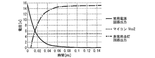
図2は、実施の形態1に係る常用電源回路2と非常用点灯回路3の電圧波形を示す図である。外部電源ACが低下すると、常用電源回路2の出力は同様に低下する。従って、本実施の形態では、常用電源回路2の出力電圧がマイコン50の電源電圧以下になる前に、非常用点灯回路3の動作を開始する。これにより、マイコン50の電源を安定して確保できる。   FIG. 2 is a diagram showing voltage waveforms of the ordinary power supply circuit 2 and the emergency lighting circuit 3 according to the first embodiment. When the external power supply AC decreases, the output of the service power supply circuit 2 also decreases. Therefore, in the present embodiment, the operation of the emergency lighting circuit 3 is started before the output voltage of the ordinary power supply circuit 2 becomes lower than the power supply voltage of the microcomputer 50. Thereby, the power supply of the microcomputer 50 can be secured stably.

図2に示される常用電源回路2の放電特性は、電解コンデンサ214と、電解コンデンサ214に接続された抵抗またはマイコン50などの消費電流によって決まる。また、図2に示される非常用点灯回路3の出力電圧特性は、マイコン50の起動方法によって決まる。ここでマイコン50の起動方法には、起動時におけるマイコン50の出力電圧、電流の時間変化の制御が含まれる。この制御には、例えばソフトスタート、フェードイン等のLED30が点灯してから緩やかに出力電圧、電流を増加させる制御がある。また、非常用点灯回路3の出力電圧特性は、スイッチング素子33を発振開始させてからコイル32が充放電する際の昇圧電圧に応じて決まる。   The discharge characteristics of the ordinary power supply circuit 2 shown in FIG. 2 are determined by the electrolytic capacitor 214 and the resistance connected to the electrolytic capacitor 214 or the current consumption of the microcomputer 50 or the like. The output voltage characteristic of the emergency lighting circuit 3 shown in FIG. Here, the starting method of the microcomputer 50 includes control of a time change of the output voltage and the current of the microcomputer 50 at the time of starting. For this control, for example, there is control for gradually increasing the output voltage and current after the LED 30 such as soft start and fade-in is turned on. The output voltage characteristic of the emergency lighting circuit 3 is determined according to the boosted voltage when the coil 32 is charged and discharged after the switching element 33 starts oscillating.

ここで、マイコン50の電源の切換えに要する時間は、マイコン50が非常時を判別する時間である。入力電圧検出回路240に入力される波形を第1抵抗212、第2抵抗213、コンデンサ211で平均化すれば、マイコン50で入力電圧を検出することが可能である。このとき、マイコン50が非常時を判別する時間は、第1抵抗212と、第2抵抗213と、コンデンサ211の時定数によって決定される。しかし、入力電圧検出回路240に入力される波形を第1抵抗212、第2抵抗213、コンデンサ211で平均化する場合、時定数が大きくなり、非常時と判定するまでの時間が長くなるおそれがある。   Here, the time required for switching the power supply of the microcomputer 50 is a time for the microcomputer 50 to determine an emergency. By averaging the waveform input to the input voltage detection circuit 240 with the first resistor 212, the second resistor 213, and the capacitor 211, the microcomputer 50 can detect the input voltage. At this time, the time when the microcomputer 50 determines an emergency is determined by the time constant of the first resistor 212, the second resistor 213, and the capacitor 211. However, when the waveform input to the input voltage detection circuit 240 is averaged by the first resistor 212, the second resistor 213, and the capacitor 211, the time constant becomes large, and the time required to determine an emergency may be long. is there.

ここで、ダイオード210のカソードには、外部電源ACからの交流電圧の全波整流波と、スイッチング素子205のスイッチングによる矩形波とが合成された電圧波形が発生する。矩形波の周波数はスイッチング周波数である。また、全波整流波は商用周波数のサイン波を全波整流した波形を有する。また、ダイオード210のカソードの電圧はトランス220の巻き数比で決まる。   Here, at the cathode of the diode 210, a voltage waveform is generated in which a full-wave rectified wave of an AC voltage from the external power supply AC and a rectangular wave generated by switching of the switching element 205 are combined. The frequency of the square wave is the switching frequency. The full-wave rectified wave has a waveform obtained by full-wave rectification of a sine wave of a commercial frequency. The voltage at the cathode of the diode 210 is determined by the turn ratio of the transformer 220.

本実施の形態の入力電圧検出回路240は、矩形波をフィルタし、全波整流波をフィルタしない。つまり、第1抵抗212と第2抵抗213は、矩形波をフィルタし、全波整流波をフィルタしない抵抗値を有する。また、コンデンサ211は、矩形波をフィルタし、全波整流波をフィルタしない静電容量を有する。このような第1抵抗212、第2抵抗213、コンデンサ211を選定することで、小さな時定数で外部電源ACの電圧を検出できる。   The input voltage detection circuit 240 of the present embodiment filters a rectangular wave and does not filter a full-wave rectified wave. That is, the first resistor 212 and the second resistor 213 have a resistance value that filters a rectangular wave and does not filter a full-wave rectified wave. The capacitor 211 has a capacitance that filters a rectangular wave and does not filter a full-wave rectified wave. By selecting the first resistor 212, the second resistor 213, and the capacitor 211, the voltage of the external power supply AC can be detected with a small time constant.

このような入力電圧検出回路240を用いて、第1抵抗212と第2抵抗213による分圧値から停電を検出する方法を説明する。入力電圧検出回路240からマイコン50への入力電圧Vは、式(1)を満たす。ここで、Nはトランス220の一次側の巻き数であり、Nはトランス220の二次側の巻き数である。Vacは外部電源ACの電圧であり、Vはダイオード210の順電圧である。Rは第1抵抗212の抵抗値であり、Rは第2抵抗213の抵抗値である。 A method for detecting a power failure based on a voltage divided by the first resistor 212 and the second resistor 213 using the input voltage detection circuit 240 will be described. Input voltage V a from the input voltage detecting circuit 240 to the microcomputer 50, satisfies the equation (1). Here, N 1 is the number of turns of the primary side of the transformer 220, N 2 is the number of turns of the secondary side of the transformer 220. Vac is the voltage of the external power supply AC, and Vf is the forward voltage of the diode 210. R 1 is the resistance of the first resistor 212, R 2 is the resistance of the second resistor 213.

Figure 2020036419
Figure 2020036419

マイコン50には、停電を判別するための入力電圧Vのピーク値の閾値を予め書き込んでおく。マイコン50は、マイコン50への入力電圧Vのピーク値が予め定められた閾値よりも小さくなると、外部電源ACが停電状態であると判別する。 The microcomputer 50, is written the threshold of the peak value of the input voltage V a for determining power outage in advance. Microcomputer 50, the peak value of the input voltage V a to the microcomputer 50 becomes smaller than a predetermined threshold value, determines that the external power source AC is in the power failure state.

図3は、実施の形態1に係る入力電圧検出回路240の電圧波形を示す図である。図3は、マイコン50に印加される入力電圧Vの電圧波形の1周期分を示す。図3では、例えばRを330kΩ、Rを27kΩ、Vを0.5V、トランス220の巻き数比N:Nを115:10としている。また、図3の実線は、外部電源ACの電圧Vacが40V、破線は外部電源ACの電圧Vacが80Vの場合の電圧波形である。 FIG. 3 is a diagram showing a voltage waveform of the input voltage detection circuit 240 according to the first embodiment. Figure 3 shows one period of the voltage waveform of the input voltage V a applied to the microcomputer 50. In Figure 3, for example, the R 1 330kΩ, the R 2 27kΩ, 0.5V to V f, turns ratio of the transformer 220 N 1: N 2 115: is 10. The solid line in FIG. 3, the voltage V ac is 40V, dashed external power supply AC voltage V ac external power source AC is a voltage waveform in the case of 80V.

図3に示されるように、外部電源ACの電圧Vacが40Vのときに非常時と判別したい場合は閾値を0.33Vとすれば良い。また、外部電源ACの電圧Vacが80Vのときに非常時と判定したい場合は閾値を0.70Vとすれば良い。このように停電を検出することで、入力電圧検出回路240によって矩形波をフィルタしなくても良い。従って、第1抵抗212、第2抵抗213の抵抗値を小さくでき、非常時と判定するまでの時間を短縮できる。 As shown in FIG. 3, when it is desired to determine an emergency when the voltage Vac of the external power supply AC is 40 V, the threshold may be set to 0.33 V. Further, when it is desired to determine that the emergency occurs when the voltage Vac of the external power supply AC is 80 V, the threshold may be set to 0.70 V. By detecting a power failure in this manner, the input voltage detection circuit 240 need not filter the rectangular wave. Therefore, the resistance values of the first resistor 212 and the second resistor 213 can be reduced, and the time required to determine an emergency can be reduced.

常用電源回路2、非常用点灯回路3、電源生成回路4の構成は図1に示されるものに限らない。常用電源回路2は、外部電源ACから電力を供給され、電池250を充電できれば良い。また、非常用点灯回路3は、電池250の出力電圧を昇圧し光源を点灯させれば良い。また、電源生成回路4において、第1ダイオード42と第2ダイオード41の一方のみが設けられても良い。   The configurations of the service power supply circuit 2, the emergency lighting circuit 3, and the power generation circuit 4 are not limited to those shown in FIG. The service power supply circuit 2 only needs to be supplied with power from an external power supply AC and charge the battery 250. In addition, the emergency lighting circuit 3 may boost the output voltage of the battery 250 and light the light source. In the power generation circuit 4, only one of the first diode 42 and the second diode 41 may be provided.

本実施の形態の非常用照明装置100は、専用型の非常灯である。つまり非常用照明装置100は、常用時は光源を点灯させず、非常時にLED30を点灯させる。これにより、常用時には充電回路である常用電源回路2により電池250を確実に充電できる。従って、非常時に確実にマイコン50の電源を確保し、LED30を点灯させることができる。なお、非常用照明装置100は、兼用型または併用型の非常灯であっても良い。この場合、非常用照明装置100は、常用時には一般の照明器具と同様に壁面などのスイッチ操作に応じて点灯または消灯し、非常時には専用型と同様にLED30を点灯させる。また、非常用照明装置100は誘導灯であっても良い。   The emergency lighting device 100 according to the present embodiment is a dedicated emergency light. That is, the emergency lighting device 100 does not turn on the light source during normal use, but turns on the LED 30 during an emergency. Thus, the battery 250 can be reliably charged by the regular power supply circuit 2 which is a charging circuit at the time of regular use. Therefore, the power supply of the microcomputer 50 can be ensured in an emergency, and the LED 30 can be turned on. The emergency lighting device 100 may be a dual-purpose or combined-type emergency light. In this case, the emergency lighting device 100 is turned on or off according to a switch operation on a wall or the like in a normal use in the same manner as a general lighting device, and turns on the LED 30 in an emergency similarly to a dedicated type. Further, the emergency lighting device 100 may be a guide light.

なお、本実施の形態で説明した技術的特徴は適宜に組み合わせて用いてもよい。   Note that the technical features described in the present embodiment may be appropriately combined and used.

1 入力フィルタ回路、11 ヒューズ、12 コンデンサ、13 ダイオードブリッジ、2 常用電源回路、10 ユニット、100 非常用照明装置、200 制御IC、201 コンデンサ、202 コンデンサ、203 抵抗、204 ダイオード、205 スイッチング素子、206 抵抗、207 フォトカプラ、208 ダイオード、209 ダイオード、210 ダイオード、211 コンデンサ、212 第1抵抗、213 第2抵抗、214 電解コンデンサ、215 抵抗、216 抵抗、217 抵抗、218 抵抗、219 抵抗、240 入力電圧検出回路、250 電池、3 非常用点灯回路、30 LED、31 コンデンサ、32 コイル、33 スイッチング素子、34 ダイオード、35 コンデンサ、36 抵抗、37 抵抗、38 センス抵抗、4 電源生成回路、40 レギュレータ、41 第2ダイオード、42 第1ダイオード、5 制御回路、50 マイコン、51 スイッチ、52 スイッチ、53 表示用LED、54 赤外線センサ、55 抵抗、56 コンデンサ、57 抵抗、58 フォトカプラ   Reference Signs List 1 input filter circuit, 11 fuse, 12 capacitor, 13 diode bridge, 2 regular power supply circuit, 10 units, 100 emergency lighting device, 200 control IC, 201 capacitor, 202 capacitor, 203 resistor, 204 diode, 205 switching element, 206 Resistor, 207 photocoupler, 208 diode, 209 diode, 210 diode, 211 capacitor, 212 first resistor, 213 second resistor, 214 electrolytic capacitor, 215 resistor, 216 resistor, 217 resistor, 218 resistor, 219 resistor, 240 input voltage Detection circuit, 250 battery, 3 emergency lighting circuit, 30 LED, 31 capacitor, 32 coil, 33 switching element, 34 diode, 35 capacitor, 36 resistor, 37 resistor , 38 sense resistor, 4 power generation circuit, 40 regulator, 41 second diode, 42 first diode, 5 control circuit, 50 microcomputer, 51 switch, 52 switch, 53 display LED, 54 infrared sensor, 55 resistor, 56 capacitor , 57 Resistance, 58 Photocoupler

Claims (10)

光源と、
電池と、
外部電源から電力を供給され、前記電池を充電する常用電源回路と、
前記電池の出力電圧を昇圧し、前記光源を点灯させる非常用点灯回路と、
前記非常用点灯回路を制御する制御部と、
を備え、
前記電池の前記出力電圧は、前記制御部の動作電圧より低く、
前記制御部は、前記常用電源回路または前記非常用点灯回路から電力を供給され動作し、前記外部電源の停電を検出すると前記非常用点灯回路を動作させることを特徴とする非常用照明装置。
Light source,
Batteries and
A power supply circuit that is supplied with power from an external power supply and charges the battery,
An emergency lighting circuit that boosts the output voltage of the battery and turns on the light source;
A control unit for controlling the emergency lighting circuit;
With
The output voltage of the battery is lower than the operation voltage of the control unit,
The emergency illuminating device, wherein the control unit is operated by being supplied with power from the normal power supply circuit or the emergency lighting circuit, and operates the emergency lighting circuit when a power failure of the external power supply is detected.
前記制御部には、前記常用電源回路の出力電圧と、前記非常用点灯回路の出力電圧のうち高いほうが供給されることを特徴とする請求項1に記載の非常用照明装置。   The emergency lighting device according to claim 1, wherein a higher one of an output voltage of the emergency power supply circuit and an output voltage of the emergency lighting circuit is supplied to the control unit. 前記電池は、前記常用電源回路の出力電圧が分圧された電圧に充電され、
前記制御部には、前記常用電源回路の前記出力電圧が供給されることを特徴とする請求項1または2に記載の非常用照明装置。
The battery is charged to a voltage obtained by dividing the output voltage of the service power supply circuit,
The emergency lighting device according to claim 1, wherein the control unit is supplied with the output voltage of the service power supply circuit.
前記非常用点灯回路から前記制御部に電力を供給する線路上に設けられ、アノードが前記非常用点灯回路側に接続され、カソードが前記制御部側に接続された第1ダイオードを備え、
前記第1ダイオードの前記カソードは、前記常用電源回路から前記制御部に電力を供給する線路に接続されることを特徴とする請求項1から3の何れか1項に記載の非常用照明装置。
A first diode is provided on a line that supplies power to the control unit from the emergency lighting circuit, an anode is connected to the emergency lighting circuit side, and a cathode is connected to the control unit side,
4. The emergency lighting device according to claim 1, wherein the cathode of the first diode is connected to a line that supplies power from the service power circuit to the control unit. 5.
前記常用電源回路から前記制御部に電力を供給する前記線路上に設けられ、アノードが前記常用電源回路側に接続され、カソードが前記第1ダイオードの前記カソードに接続された第2ダイオードを備えることを特徴とする請求項4に記載の非常用照明装置。   A second diode is provided on the line that supplies power from the service power circuit to the control unit, an anode is connected to the service power circuit side, and a cathode is connected to the cathode of the first diode. The emergency lighting device according to claim 4, wherein: 前記第1ダイオードの前記カソードと前記制御部との間に設けられたレギュレータを備えることを特徴とする請求項4または5に記載の非常用照明装置。   The emergency lighting device according to claim 4, further comprising a regulator provided between the cathode of the first diode and the control unit. 前記常用電源回路は、
スイッチング素子と、
トランスと、
前記トランスの二次側に直列に接続され、前記常用電源回路への入力電圧を検出する入力電圧検出回路と、
を備え、
前記制御部は、前記入力電圧検出回路の検出電圧から停電を検出することを特徴とする請求項1から6の何れか1項に記載の非常用照明装置。
The service power supply circuit,
A switching element;
With a transformer
An input voltage detection circuit that is connected in series to a secondary side of the transformer and detects an input voltage to the service power supply circuit;
With
The emergency lighting device according to claim 1, wherein the control unit detects a power failure based on a detection voltage of the input voltage detection circuit.
前記外部電源は交流電源であり、
前記入力電圧検出回路には、前記外部電源からの交流電圧の全波整流波と、前記スイッチング素子のスイッチングによる矩形波とが合成された電圧波形が入力され、
前記入力電圧検出回路は、前記矩形波をフィルタし、前記全波整流波をフィルタしないことを特徴とする請求項7に記載の非常用照明装置。
The external power supply is an AC power supply,
A voltage waveform obtained by combining a full-wave rectified wave of an AC voltage from the external power supply and a rectangular wave generated by switching of the switching element is input to the input voltage detection circuit,
The emergency lighting device according to claim 7, wherein the input voltage detection circuit filters the rectangular wave and does not filter the full-wave rectified wave.
前記入力電圧検出回路は、第1抵抗と第2抵抗から形成される直列回路を有し、
前記第1抵抗と前記第2抵抗は、前記矩形波をフィルタし、前記全波整流波をフィルタしない抵抗値を有し、
前記制御部は、前記第1抵抗と前記第2抵抗による分圧値から停電を検出することを特徴とする請求項8に記載の非常用照明装置。
The input voltage detection circuit has a series circuit formed by a first resistor and a second resistor,
The first resistor and the second resistor have a resistance value that filters the rectangular wave and does not filter the full-wave rectified wave,
The emergency lighting device according to claim 8, wherein the control unit detects a power failure based on a voltage divided by the first resistor and the second resistor.
前記入力電圧検出回路は、アノードが前記トランスの二次側に接続され、カソードが前記直列回路の一端に接続されたダイオードを備え、
前記トランスの一次側の巻き数Nと、前記トランスの二次側の巻き数Nと、前記外部電源の電圧Vacと、前記ダイオードの順電圧Vと、前記第1抵抗の抵抗値Rと、前記第2抵抗の抵抗値Rと、前記入力電圧検出回路から前記制御部への入力電圧Vと、は、
Figure 2020036419
を満たし、
前記制御部は、前記入力電圧Vのピーク値が予め定められた閾値よりも小さくなると前記外部電源が停電状態であると判別することを特徴とする請求項9に記載の非常用照明装置。
The input voltage detection circuit includes a diode having an anode connected to the secondary side of the transformer and a cathode connected to one end of the series circuit,
Wherein the number of turns N 1 of the primary side of the transformer, the winding number N 2 of the secondary side of the transformer, and the voltage V ac of the external power supply, and the forward voltage V f of the diodes, the first resistor resistance value and R 1, and the resistance value R 2 of the second resistor, and the input voltage V a from the input voltage detecting circuit to said control unit, the
Figure 2020036419
The filling,
Wherein the control unit, emergency lighting device according to claim 9, characterized in that to determine that the external power supply and the peak value is smaller than a predetermined threshold value of the input voltage V a is a power failure state.
JP2018159635A 2018-08-28 2018-08-28 Emergency lighting fixture Pending JP2020036419A (en)

Priority Applications (1)

Application Number Priority Date Filing Date Title
JP2018159635A JP2020036419A (en) 2018-08-28 2018-08-28 Emergency lighting fixture

Applications Claiming Priority (1)

Application Number Priority Date Filing Date Title
JP2018159635A JP2020036419A (en) 2018-08-28 2018-08-28 Emergency lighting fixture

Publications (1)

Publication Number Publication Date
JP2020036419A true JP2020036419A (en) 2020-03-05

Family

ID=69668857

Family Applications (1)

Application Number Title Priority Date Filing Date
JP2018159635A Pending JP2020036419A (en) 2018-08-28 2018-08-28 Emergency lighting fixture

Country Status (1)

Country Link
JP (1) JP2020036419A (en)

Cited By (3)

* Cited by examiner, † Cited by third party
Publication number Priority date Publication date Assignee Title
JP2021190412A (en) * 2020-05-26 2021-12-13 リーダーソン ライティング カンパニー リミテッドLeedarson Lighting Co., Ltd. Emergency lamp control circuit, emergency lamp control device, and lighting fixture
KR102469414B1 (en) * 2022-01-12 2022-11-22 루멘전광 주식회사 Driving circuit for emergency light
JP7476642B2 (en) 2020-04-21 2024-05-01 三菱電機株式会社 Emergency devices, lighting equipment

Citations (2)

* Cited by examiner, † Cited by third party
Publication number Priority date Publication date Assignee Title
JP2006060949A (en) * 2004-08-23 2006-03-02 Matsushita Electric Ind Co Ltd Power supply backup unit and electronic control device using the same
JP2011034977A (en) * 2010-10-20 2011-02-17 Toshiba Lighting & Technology Corp Led lighting device and lighting system

Patent Citations (2)

* Cited by examiner, † Cited by third party
Publication number Priority date Publication date Assignee Title
JP2006060949A (en) * 2004-08-23 2006-03-02 Matsushita Electric Ind Co Ltd Power supply backup unit and electronic control device using the same
JP2011034977A (en) * 2010-10-20 2011-02-17 Toshiba Lighting & Technology Corp Led lighting device and lighting system

Cited By (3)

* Cited by examiner, † Cited by third party
Publication number Priority date Publication date Assignee Title
JP7476642B2 (en) 2020-04-21 2024-05-01 三菱電機株式会社 Emergency devices, lighting equipment
JP2021190412A (en) * 2020-05-26 2021-12-13 リーダーソン ライティング カンパニー リミテッドLeedarson Lighting Co., Ltd. Emergency lamp control circuit, emergency lamp control device, and lighting fixture
KR102469414B1 (en) * 2022-01-12 2022-11-22 루멘전광 주식회사 Driving circuit for emergency light

Similar Documents

Publication Publication Date Title
JP5554108B2 (en) Overcurrent prevention type power supply device and lighting fixture using the same
WO2016125561A1 (en) Switching power supply device
US9723666B2 (en) Lighting device and lighting fixture using same
JP5512171B2 (en) Power supply for lighting
JP2010166695A (en) Charging circuit and lighting fixture
JP2020036419A (en) Emergency lighting fixture
JP6323149B2 (en) Power supply device for lighting with power failure compensation function and lighting device
JP2014171313A (en) Dc/dc converter
JP6169329B2 (en) Power supply device and lighting device
JP6553415B2 (en) Switching converter, lighting apparatus using the same
JP2015042030A (en) Led power supply and led illuminating device
JP6273100B2 (en) Lighting device
JP7288240B2 (en) Power supply and emergency lights
JP6562354B2 (en) Power supply device and lighting fixture
JP5079043B2 (en) Power supply device, discharge lamp lighting device including the power supply device, and lighting fixture including the discharge lamp lighting device
JP6173183B2 (en) Emergency lighting unit and emergency light fixture
JP7294007B2 (en) Power supply and emergency lighting
JP2016077060A (en) Charging circuit, and emergency lamp lighting device
JP2013246938A (en) Illuminating device, and illuminating fixture
JP7476642B2 (en) Emergency devices, lighting equipment
JP7327123B2 (en) Lighting device and lighting device
JP7211079B2 (en) emergency lighting system
JP2022107412A (en) Lighting unit and emergency lighting device
JP7027964B2 (en) Lighting equipment, lighting fixtures and lighting systems
JP2022061081A (en) Emergency lighting device

Legal Events

Date Code Title Description
A621 Written request for application examination

Free format text: JAPANESE INTERMEDIATE CODE: A621

Effective date: 20210720

A977 Report on retrieval

Free format text: JAPANESE INTERMEDIATE CODE: A971007

Effective date: 20220428

A131 Notification of reasons for refusal

Free format text: JAPANESE INTERMEDIATE CODE: A131

Effective date: 20220510

A521 Request for written amendment filed

Free format text: JAPANESE INTERMEDIATE CODE: A523

Effective date: 20220617

A02 Decision of refusal

Free format text: JAPANESE INTERMEDIATE CODE: A02

Effective date: 20221018

C60 Trial request (containing other claim documents, opposition documents)

Free format text: JAPANESE INTERMEDIATE CODE: C60

Effective date: 20221206