JP2020032260A - Methods and devices with leak detection - Google Patents
Methods and devices with leak detection Download PDFInfo
- Publication number
- JP2020032260A JP2020032260A JP2019213173A JP2019213173A JP2020032260A JP 2020032260 A JP2020032260 A JP 2020032260A JP 2019213173 A JP2019213173 A JP 2019213173A JP 2019213173 A JP2019213173 A JP 2019213173A JP 2020032260 A JP2020032260 A JP 2020032260A
- Authority
- JP
- Japan
- Prior art keywords
- leak
- flow
- threshold
- event
- measurement
- Prior art date
- Legal status (The legal status is an assumption and is not a legal conclusion. Google has not performed a legal analysis and makes no representation as to the accuracy of the status listed.)
- Granted
Links
Images


Classifications
-
- A—HUMAN NECESSITIES
- A61—MEDICAL OR VETERINARY SCIENCE; HYGIENE
- A61M—DEVICES FOR INTRODUCING MEDIA INTO, OR ONTO, THE BODY; DEVICES FOR TRANSDUCING BODY MEDIA OR FOR TAKING MEDIA FROM THE BODY; DEVICES FOR PRODUCING OR ENDING SLEEP OR STUPOR
- A61M16/00—Devices for influencing the respiratory system of patients by gas treatment, e.g. mouth-to-mouth respiration; Tracheal tubes
- A61M16/0003—Accessories therefor, e.g. sensors, vibrators, negative pressure
-
- A—HUMAN NECESSITIES
- A61—MEDICAL OR VETERINARY SCIENCE; HYGIENE
- A61M—DEVICES FOR INTRODUCING MEDIA INTO, OR ONTO, THE BODY; DEVICES FOR TRANSDUCING BODY MEDIA OR FOR TAKING MEDIA FROM THE BODY; DEVICES FOR PRODUCING OR ENDING SLEEP OR STUPOR
- A61M16/00—Devices for influencing the respiratory system of patients by gas treatment, e.g. mouth-to-mouth respiration; Tracheal tubes
- A61M16/0051—Devices for influencing the respiratory system of patients by gas treatment, e.g. mouth-to-mouth respiration; Tracheal tubes with alarm devices
-
- A—HUMAN NECESSITIES
- A61—MEDICAL OR VETERINARY SCIENCE; HYGIENE
- A61M—DEVICES FOR INTRODUCING MEDIA INTO, OR ONTO, THE BODY; DEVICES FOR TRANSDUCING BODY MEDIA OR FOR TAKING MEDIA FROM THE BODY; DEVICES FOR PRODUCING OR ENDING SLEEP OR STUPOR
- A61M16/00—Devices for influencing the respiratory system of patients by gas treatment, e.g. mouth-to-mouth respiration; Tracheal tubes
- A61M16/0057—Pumps therefor
- A61M16/0066—Blowers or centrifugal pumps
- A61M16/0069—Blowers or centrifugal pumps the speed thereof being controlled by respiratory parameters, e.g. by inhalation
-
- A—HUMAN NECESSITIES
- A61—MEDICAL OR VETERINARY SCIENCE; HYGIENE
- A61M—DEVICES FOR INTRODUCING MEDIA INTO, OR ONTO, THE BODY; DEVICES FOR TRANSDUCING BODY MEDIA OR FOR TAKING MEDIA FROM THE BODY; DEVICES FOR PRODUCING OR ENDING SLEEP OR STUPOR
- A61M16/00—Devices for influencing the respiratory system of patients by gas treatment, e.g. mouth-to-mouth respiration; Tracheal tubes
- A61M16/021—Devices for influencing the respiratory system of patients by gas treatment, e.g. mouth-to-mouth respiration; Tracheal tubes operated by electrical means
- A61M16/022—Control means therefor
- A61M16/024—Control means therefor including calculation means, e.g. using a processor
- A61M16/026—Control means therefor including calculation means, e.g. using a processor specially adapted for predicting, e.g. for determining an information representative of a flow limitation during a ventilation cycle by using a root square technique or a regression analysis
-
- G—PHYSICS
- G01—MEASURING; TESTING
- G01M—TESTING STATIC OR DYNAMIC BALANCE OF MACHINES OR STRUCTURES; TESTING OF STRUCTURES OR APPARATUS, NOT OTHERWISE PROVIDED FOR
- G01M3/00—Investigating fluid-tightness of structures
- G01M3/02—Investigating fluid-tightness of structures by using fluid or vacuum
- G01M3/04—Investigating fluid-tightness of structures by using fluid or vacuum by detecting the presence of fluid at the leakage point
-
- G—PHYSICS
- G01—MEASURING; TESTING
- G01M—TESTING STATIC OR DYNAMIC BALANCE OF MACHINES OR STRUCTURES; TESTING OF STRUCTURES OR APPARATUS, NOT OTHERWISE PROVIDED FOR
- G01M3/00—Investigating fluid-tightness of structures
- G01M3/02—Investigating fluid-tightness of structures by using fluid or vacuum
- G01M3/26—Investigating fluid-tightness of structures by using fluid or vacuum by measuring rate of loss or gain of fluid, e.g. by pressure-responsive devices, by flow detectors
- G01M3/28—Investigating fluid-tightness of structures by using fluid or vacuum by measuring rate of loss or gain of fluid, e.g. by pressure-responsive devices, by flow detectors for pipes, cables or tubes; for pipe joints or seals; for valves ; for welds
- G01M3/2807—Investigating fluid-tightness of structures by using fluid or vacuum by measuring rate of loss or gain of fluid, e.g. by pressure-responsive devices, by flow detectors for pipes, cables or tubes; for pipe joints or seals; for valves ; for welds for pipes
-
- A—HUMAN NECESSITIES
- A61—MEDICAL OR VETERINARY SCIENCE; HYGIENE
- A61M—DEVICES FOR INTRODUCING MEDIA INTO, OR ONTO, THE BODY; DEVICES FOR TRANSDUCING BODY MEDIA OR FOR TAKING MEDIA FROM THE BODY; DEVICES FOR PRODUCING OR ENDING SLEEP OR STUPOR
- A61M16/00—Devices for influencing the respiratory system of patients by gas treatment, e.g. mouth-to-mouth respiration; Tracheal tubes
- A61M16/0003—Accessories therefor, e.g. sensors, vibrators, negative pressure
- A61M2016/0015—Accessories therefor, e.g. sensors, vibrators, negative pressure inhalation detectors
- A61M2016/0018—Accessories therefor, e.g. sensors, vibrators, negative pressure inhalation detectors electrical
- A61M2016/0021—Accessories therefor, e.g. sensors, vibrators, negative pressure inhalation detectors electrical with a proportional output signal, e.g. from a thermistor
-
- A—HUMAN NECESSITIES
- A61—MEDICAL OR VETERINARY SCIENCE; HYGIENE
- A61M—DEVICES FOR INTRODUCING MEDIA INTO, OR ONTO, THE BODY; DEVICES FOR TRANSDUCING BODY MEDIA OR FOR TAKING MEDIA FROM THE BODY; DEVICES FOR PRODUCING OR ENDING SLEEP OR STUPOR
- A61M16/00—Devices for influencing the respiratory system of patients by gas treatment, e.g. mouth-to-mouth respiration; Tracheal tubes
- A61M16/0003—Accessories therefor, e.g. sensors, vibrators, negative pressure
- A61M2016/003—Accessories therefor, e.g. sensors, vibrators, negative pressure with a flowmeter
- A61M2016/0033—Accessories therefor, e.g. sensors, vibrators, negative pressure with a flowmeter electrical
- A61M2016/0039—Accessories therefor, e.g. sensors, vibrators, negative pressure with a flowmeter electrical in the inspiratory circuit
-
- A—HUMAN NECESSITIES
- A61—MEDICAL OR VETERINARY SCIENCE; HYGIENE
- A61M—DEVICES FOR INTRODUCING MEDIA INTO, OR ONTO, THE BODY; DEVICES FOR TRANSDUCING BODY MEDIA OR FOR TAKING MEDIA FROM THE BODY; DEVICES FOR PRODUCING OR ENDING SLEEP OR STUPOR
- A61M2205/00—General characteristics of the apparatus
- A61M2205/15—Detection of leaks
-
- A—HUMAN NECESSITIES
- A61—MEDICAL OR VETERINARY SCIENCE; HYGIENE
- A61M—DEVICES FOR INTRODUCING MEDIA INTO, OR ONTO, THE BODY; DEVICES FOR TRANSDUCING BODY MEDIA OR FOR TAKING MEDIA FROM THE BODY; DEVICES FOR PRODUCING OR ENDING SLEEP OR STUPOR
- A61M2205/00—General characteristics of the apparatus
- A61M2205/33—Controlling, regulating or measuring
- A61M2205/3327—Measuring
-
- A—HUMAN NECESSITIES
- A61—MEDICAL OR VETERINARY SCIENCE; HYGIENE
- A61M—DEVICES FOR INTRODUCING MEDIA INTO, OR ONTO, THE BODY; DEVICES FOR TRANSDUCING BODY MEDIA OR FOR TAKING MEDIA FROM THE BODY; DEVICES FOR PRODUCING OR ENDING SLEEP OR STUPOR
- A61M2205/00—General characteristics of the apparatus
- A61M2205/50—General characteristics of the apparatus with microprocessors or computers
- A61M2205/502—User interfaces, e.g. screens or keyboards
- A61M2205/505—Touch-screens; Virtual keyboard or keypads; Virtual buttons; Soft keys; Mouse touches
Abstract
Description
本技術は、呼吸治療装置と関連付けられた漏れの検出のための方法及び装置に関する。
より詳細には、本技法の幾つかの実施の形態は、持続的気道陽圧(continuous positive
airway pressure)治療に対応した呼吸治療装置における自動漏れ検出を含むことができ
る。
The present technology relates to a method and apparatus for detecting leaks associated with a respiratory treatment device.
More specifically, some embodiments of the present technique employ continuous positive airway pressure.
Automatic leak detection in a respiratory treatment device corresponding to (airway pressure) treatment may be included.
[関連出願の相互参照]
本願は、2010年7月30日に出願された米国仮特許出願第61/396,247号
の出願日の利益を主張するものであり、この仮特許出願の開示内容を引用することにより
、本明細書の一部を成すものとする。
[Cross-reference of related applications]
This application claims the benefit of the filing date of US Provisional Patent Application No. 61 / 396,247, filed July 30, 2010, which is hereby incorporated by reference. Shall form part of the specification.
閉塞型睡眠時無呼吸(OSA)を有する患者は、睡眠中、患者の覚醒によってのみ終わ
る再発性無呼吸又は減呼吸を経験する場合がある。OSAを有する患者の最良の治療形態
は、接続ホース及びマスクを介してブロワ(例えばコンプレッサ)によって加えられる一
定気道陽圧(CPAP:constant positive airway pressure)である。陽圧は、吸気中
、患者の気道が潰れるのを防ぎ、それにより、再発性無呼吸又は減呼吸及びそれらの続発
症を防ぐ。そのような呼吸治療装置は、患者の呼吸サイクル中、適切なときに1つ又は複
数の治療圧力で清潔で呼吸可能なガス(通常、酸素補給あり又はなしの空気)の供給を患
者に供給するように機能することができる。
Patients with obstructive sleep apnea (OSA) may experience recurrent apnea or hypopnea during sleep that is only terminated by the patient's awakening. The best form of treatment for patients with OSA is constant positive airway pressure (CPAP) applied by a blower (eg, a compressor) through a connecting hose and mask. Positive pressure prevents the patient's airway from collapsing during inspiration, thereby preventing recurrent apnea or hypopnea and their sequelae. Such respiratory treatment devices provide a supply of clean, breathable gas (typically air with or without oxygen supplementation) to the patient at one or more treatment pressures at appropriate times during the patient's breathing cycle. Can function as follows.
呼吸治療装置は通常、フロー生成器と、エアフィルタと、マスク又はカニューレと、フ
ロー生成器をマスクに接続する空気送達管と、様々なセンサと、マイクロプロセッサに基
づくコントローラとを備える。フロー生成器は、サーボ制御されるモータ及びインペラを
備えることができる。フロー生成器は、モータ速度制御への代替又は追加として、患者に
送達される圧力を変更する手段として、空気を大気中に排出可能な弁を備えることもでき
る。センサは、特に、圧力変換器、呼吸気流計、差圧変換器等のフローセンサ等を用いて
モータ速度、ガス体積流量、及び流出圧を測定する。この装置は、オプションで、空気送
達管の経路に加湿及び/又は加熱要素を備えることができる。コントローラは、一体化さ
れたデータ検索/転送機能及び表示機能とともに、又はこれら機能なしでデータ記憶容量
を含むことができる。
Respiratory treatment devices typically include a flow generator, an air filter, a mask or cannula, an air delivery tube connecting the flow generator to the mask, various sensors, and a microprocessor-based controller. The flow generator can include a servo-controlled motor and an impeller. The flow generator may, as an alternative or in addition to motor speed control, include a valve capable of venting air to the atmosphere as a means of changing the pressure delivered to the patient. The sensors measure the motor speed, gas volume flow, and outflow pressure using flow sensors, such as pressure transducers, respiratory anemometers, differential pressure transducers, among others. The device may optionally include a humidifying and / or heating element in the path of the air delivery tube. The controller may include data storage with or without integrated data retrieval / transfer and display functions.
そのようなデバイスを用いた呼吸治療中、被験者の呼吸気流を測定することが多くの場
合に有用である。これはフローセンサを用いて求めることができる。一方、マスクと患者
との間の漏れが一般的である。このため、フローセンサは、呼吸気流と漏れを通じたフロ
ーとの和を測定することができる。漏れを通じた瞬時フローが知られている場合、呼吸気
流は、漏れを通じたフローを呼吸気流計におけるフローから減算することによって計算す
ることができる。
During respiratory treatment with such a device, it is often useful to measure the respiratory airflow of the subject. This can be determined using a flow sensor. On the other hand, leaks between the mask and the patient are common. Thus, the flow sensor can measure the sum of the respiratory airflow and the flow through the leak. If the instantaneous flow through the leak is known, the respiratory airflow can be calculated by subtracting the flow through the leak from the flow in the pneumotachograph.
漏れを所与としてフローを補正する既知の方法は、(i)漏れが実質的に一定であるこ
と、及び(ii)十分長い時間にわたって、吸気及び呼気の呼吸気流が相殺されること、
を仮定することができる。これらの仮定が満たされる場合、十分長い期間にわたってフロ
ーセンサを通じた平均フローは漏れの大きさと等しくなり、このとき真の呼吸気流は説明
したように計算される。
Known methods of correcting flow given a leak include (i) that the leak is substantially constant, and (ii) that the inspiratory and expiratory respiratory airflows are offset for a sufficiently long period of time;
Can be assumed. If these assumptions are satisfied, the average flow through the flow sensor over a sufficiently long period will be equal to the magnitude of the leak, at which time the true respiratory airflow will be calculated as described.
漏れのコンダクタンスを計算することによって漏れを測定することが知られている。米
国特許第6,659,101号に記載されているように、コンダクタンスは、低域通過フ
ィルタリングされた呼吸気流測定値(measure)を、マスク圧力測定値の低域通過フィル
タリングされた平方根で除算することによって求めることができる。このとき、瞬時漏れ
は、コンダクタンスにマスク圧力の平方根を乗算することによって求めることができる。
It is known to measure leaks by calculating the conductance of the leak. As described in US Pat. No. 6,659,101, conductance divides the low-pass filtered respiratory airflow measure by the low-pass filtered square root of the mask pressure measurement. Can be obtained by: At this time, the instantaneous leak can be obtained by multiplying the conductance by the square root of the mask pressure.
Berthon-Jonesに対する米国特許第5,704,345号に記載されているように、弁
状の漏れの存在のインデックスを求めることも知られている。インデックスは、呼気の最
初の0.5秒の間のピークフローと、呼気の第2の0.5秒の間の平均フローとの比とし
て計算される。
It is also known to determine the index of the presence of a valve-like leak, as described in US Pat. No. 5,704,345 to Berthon-Jones. The index is calculated as the ratio of the peak flow during the first 0.5 seconds of expiration to the average flow during the second 0.5 seconds of expiration.
別の技術が、欧州特許出願公開第0714670号に開示されている。この技術は、圧
力に依拠した漏れ成分の計算を含む。この方法論は、呼気事象の開始及び次の呼気事象の
開始の発生を正確に知ることに頼る。換言すれば、漏れ計算は、既知の呼吸にわたる平均
として形成され、後続の呼吸に適用される。
Another technique is disclosed in EP-A-0714670. This technique involves calculating a leak component based on pressure. This methodology relies on knowing exactly the onset of an expiration event and the onset of the next expiration event. In other words, the leak calculation is formed as an average over a known breath and applied to subsequent breaths.
口漏れは、鼻CPAP治療等の呼吸治療処置に対し、依然として多くの問題を呈する場
合がある。そのような問題は以下を含む場合がある。すなわち、
1.患者の覚醒率及び/又は無呼吸及び減呼吸インデックス(「AHI」)が漏れに起
因して増大し、患者の睡眠構造に影響を及ぼす可能性がある。
2.鼻吸気フローが口から漏れた結果として、換気サポートが低減される場合がある。
これは二相性/VPAP治療を受けている患者にとって特に問題である。
3.一方向鼻気流が確立され、上気道の脱水、鼻づまり(congestion)及び炎症性伝達
物質の放出につながる場合がある。さらに、一方向鼻フローによって鼻気道の抵抗が増大
する場合があり、これにより、今度は口フローの傾向が増大し、結果として更に多くの口
漏れを生成する周期となる場合がある。
4.鼻の症状に起因して患者の順応性が低減する場合がある。
5.患者フロー推定値及びフロー生成器制御アルゴリズムにおいて誤りのある挙動が生
じる。なぜなら、結果として得られる測定フロー信号全体が、口フローを正しく計上して
いない場合があるためである。
6.子供の口呼吸は、その顎顔面の発育に影響を及ぼすことが示されている。特に、過
剰な口気流によって、歯並び不良(歯性不正咬合)、頭部前方姿勢、不規則な鎖骨成長、
及び耳感染症への感受性増加につながる可能性がある。
Mouth leaks can still present many problems for respiratory treatment procedures such as nasal CPAP treatment. Such issues may include: That is,
1. A patient's arousal rate and / or apnea and hypopnea index ("AHI") may increase due to leakage and affect the patient's sleep structure.
2. Ventilation support may be reduced as a result of nasal inspiratory flow leaking from the mouth.
This is particularly problematic for patients receiving biphasic / VPAP treatment.
3. One-way nasal airflow may be established, leading to dehydration of the upper respiratory tract, nasal congestion and release of inflammatory mediators. In addition, one-way nasal flow may increase nasal airway resistance, which in turn may increase the tendency of mouth flow, resulting in a cycle that produces more mouth leaks.
4. Nasal symptoms may reduce patient adaptability.
5. Erroneous behaviors occur in the patient flow estimates and the flow generator control algorithm. This is because the resulting entire measurement flow signal may not correctly account for the mouth flow.
6. Mouth breathing in children has been shown to affect its maxillofacial development. In particular, due to excessive mouth air flow, malalignment of teeth (dental malocclusion), anterior head posture, irregular clavicle growth,
And increased susceptibility to ear infections.
OSA等の上気道症状(upper respiratory condition)を検出するための装置及び/
又は治療するための装置等の呼吸治療装置において実施することができる、漏れを検出及
び/又は測定するための更なる方法を開発することが望ましい場合がある。
A device for detecting upper respiratory conditions such as OSA and / or
Or it may be desirable to develop additional methods for detecting and / or measuring leaks that can be implemented in a respiratory treatment device, such as a device for treating.
本技術の幾つかの実施の形態の第1の態様は、漏れを検出するための方法及び装置を提
供することである。
A first aspect of some embodiments of the present technology is to provide a method and apparatus for detecting leaks.
本技術の幾つかの実施の形態の別の態様は、患者の呼吸フロー信号を測定する装置にお
ける漏れを検出することである。
Another aspect of some embodiments of the present technology is to detect leaks in a device that measures a patient's respiratory flow signal.
本技術のまた更なる態様は、持続的気道陽圧デバイス等の呼吸治療装置における漏れの
検出を実施することである。
A still further aspect of the present technology is to perform leak detection in a respiratory treatment device, such as a continuous positive airway pressure device.
本技術の幾つかの実施の形態は、漏れ検出デバイス等によってプロセッサを制御して、
呼吸可能なガスの測定フロー等から漏れを検出する方法を含む。そのような方法において
、前記プロセッサは、呼吸可能なガスの測定フローから複数の特徴を求めることができる
。次に、前記プロセッサは、前記複数の特徴を解析して、該複数の特徴に基づいて漏れ事
象を確定することができる。また、前記プロセッサは、複数の異なるタイプの漏れから前
記漏れ事象を分類することができる。そのような幾つかの実施の形態では、前記複数の異
なるタイプの漏れは、連続口漏れと弁状口漏れとを含むことができる。
Some embodiments of the present technology control the processor, such as by a leak detection device,
It includes a method for detecting a leak from a measurement flow of breathable gas or the like. In such a method, the processor may determine a plurality of features from the measured flow of breathable gas. Next, the processor may analyze the plurality of features and determine a leak event based on the plurality of features. Also, the processor can classify the leak event from a plurality of different types of leaks. In some such embodiments, the plurality of different types of leaks can include continuous mouth leaks and valve mouth leaks.
幾つかのそのような実施の形態では、前記複数の特徴は、換気量の測定値及び/又は瞬
時漏れ測定値を含むことができる。さらに、前記解析は、前記換気量測定値及び前記瞬時
漏れ測定値の同時変化を求めることを含むことができる。前記同時変化は、前記瞬時漏れ
測定値の増加及び前記換気量の測定値の減少とすることができる。またさらに、前記解析
は、前記換気量測定値及び前記瞬時漏れ測定値の更なる同時変化を求めることを含むこと
ができる。そのような場合、前記更なる同時変化は、前記換気量の測定値の増加及び前記
瞬時漏れ測定値の減少とすることができる。さらに、幾つかの実施の形態では、前記解析
は前記漏れ事象の持続時間の計算を含むことができ、ここで、該持続時間は前記同時変化
とともに開始し、前記更なる同時変化とともに終了する。
In some such embodiments, the plurality of characteristics may include a measure of ventilation and / or a measure of instantaneous leak. Further, the analysis can include determining a simultaneous change in the ventilation measurement and the instantaneous leak measurement. The simultaneous change may be an increase in the instantaneous leak measurement and a decrease in the ventilation measurement. Still further, the analysis can include determining further simultaneous changes in the ventilation measurements and the instantaneous leak measurements. In such a case, the further simultaneous change may be an increase in the measurement of the ventilation and a decrease in the instantaneous leak measurement. Further, in some embodiments, the analysis can include calculating a duration of the leak event, where the duration starts with the concurrent change and ends with the further concurrent change.
そのような幾つかの場合、前記呼吸可能なガスの測定フローからの前記複数の特徴は、
呼吸における最大フローの或る割合未満に下降したフローの前記測定値と関連付けられた
第1の値と、前記呼吸における前記最大フローの前記割合を超えて上昇したフローの前記
測定値と関連付けられた第2の値とを含むことができる。そのような場合、前記解析は、
前記第1の値の発生と、前記第2の値の発生との間の時間を表す持続時間値を求めること
を含むことができる。前記解析は、前記持続時間値を閾値と比較することも含むことがで
きる。そのような場合、前記解析は、前記持続時間値が前記閾値未満に下降したときに前
記漏れ事象の開始を検出することができる。同様に、前記解析は、前記持続時間値が前記
閾値を満たすか又は超えたときに前記漏れ事象の終了を検出することができる。
In some such cases, the plurality of features from the measurement flow of breathable gas include:
A first value associated with the measure of flow falling below a certain percentage of the maximum flow in the breath and a measure associated with the measure of flow rising above the percentage of the maximum flow in the breath And a second value. In such a case, the analysis
The method may include determining a duration value representing a time between the occurrence of the first value and the occurrence of the second value. The analysis may also include comparing the duration value to a threshold. In such a case, the analysis may detect the onset of the leak event when the duration value falls below the threshold. Similarly, the analysis may detect the end of the leak event when the duration value meets or exceeds the threshold.
本技術の幾つかの実施の形態は、プロセッサを制御して漏れを検出する方法を含む。こ
れは呼吸可能なガスの測定フローから行うことができる。該プロセッサの該方法は、呼吸
可能なガスの測定フローから換気量測定値と漏れ測定値とを求めることを含むことができ
る。次に、前記プロセッサは、前記換気量測定値及び前記漏れ測定値を解析して、前記換
気量測定値及び前記漏れ測定値の同時変化を検出することができる。次に、前記プロセッ
サは、前記同時変化に基づいて漏れ事象を特定することができる。そのような幾つかの実
施の形態では、前記同時変化は、前記漏れ測定値の増加と、前記換気量測定値の減少とす
ることができる。代替的に、前記同時変化は、前記漏れ測定値の減少と、前記換気量測定
値の増加とすることができる。そのようなプロセッサにおいて、前記換気量測定値及び前
記漏れ測定値の前記解析によって、該換気量測定値及び該漏れ測定値の更なる同時変化を
検出することができる。オプションで、前記プロセッサは、前記持続時間が前記同時変化
とともに開始し、前記更なる同時変化とともに終了するように前記漏れ事象の持続時間を
求めることができる。
Some embodiments of the present technology include a method for controlling a processor to detect a leak. This can be done from the breathable gas measurement flow. The method of the processor may include determining a ventilation measurement and a leak measurement from the measurement flow of breathable gas. Next, the processor may analyze the ventilation measurements and the leak measurements to detect simultaneous changes in the ventilation measurements and the leak measurements. Next, the processor may identify a leak event based on the simultaneous change. In some such embodiments, the simultaneous changes can be an increase in the leak measurement and a decrease in the ventilation measurement. Alternatively, the simultaneous changes can be a decrease in the leak measurement and an increase in the ventilation measurement. In such a processor, the simultaneous analysis of the ventilation measurement and the leakage measurement may detect further simultaneous changes in the ventilation measurement and the leakage measurement. Optionally, the processor may determine a duration of the leak event such that the duration starts with the coincidence and ends with the further coincidence.
そのような幾つかの実施の形態では、前記同時変化は、前記漏れ測定値の増加及び前記
換気量測定値の減少とすることができ、前記更なる同時変化は、前記漏れ測定値の減少及
び前記換気量測定値の増加とすることができる。オプションで、前記換気量測定値は、二
分割されたフローの前記測定値の低域通過フィルタリングされた絶対値とすることができ
、前記漏れ測定値は、計算された漏れコンダクタンスの関数として求められた瞬時漏れと
することができる。
In some such embodiments, the simultaneous change may be an increase in the leak measurement and a decrease in the ventilation measurement, and the further simultaneous change may include a decrease in the leak measurement and This may be an increase in the ventilation measurement. Optionally, the ventilation measurement may be a low-pass filtered absolute value of the measurement of the bipartite flow, and the leak measurement is determined as a function of a calculated leak conductance. Instantaneous leakage.
幾つかのそのような実施の形態では、前記解析は、前記換気量測定値及び前記漏れ測定
値を表すデータを用いて共分散を求めることを含むことができる。前記解析は、前記漏れ
測定値を表すデータを用いて勾配を求めることも含むことができる。オプションで、前記
勾配と前記共分散との積は積分することができる。そのような場合、前記プロセッサは、
前記積分された積と閾値との比較に基づいて連続口漏れをスコアリングすることによって
前記漏れ事象を特定することができる。
In some such embodiments, the analysis may include determining a covariance using data representing the ventilation measurements and the leak measurements. The analysis can also include determining a slope using data representing the leak measurement. Optionally, the product of the gradient and the covariance can be integrated. In such a case, the processor comprises:
The leak event can be identified by scoring continuous mouth leaks based on a comparison of the integrated product and a threshold.
本技術のまた更なる実施の形態は、漏れ検出デバイスのプロセッサを制御して、呼吸可
能なガスの測定フロー等から漏れを検出する方法を含むことができる。前記プロセッサの
前記方法は、呼吸において閾値未満に下降したフローの前記測定値と関連付けられた第1
の発生と、前記呼吸において前記閾値を超えて上昇したフローの前記測定値と関連付けら
れた第2の発生とを求めることを含むことができる。次に、前記プロセッサは、前記第1
の発生及び前記第2の発生と関連付けられた持続時間を解析することができる。前記プロ
セッサは、この解析に基づいて漏れ事象を特定することもできる。
Still further embodiments of the present technology can include a method of controlling a processor of a leak detection device to detect a leak, such as from a measurement flow of breathable gas. The method of the processor may further include a first step associated with the measurement of the flow falling below a threshold in breathing.
And determining a second occurrence associated with the measurement of a flow that has risen above the threshold in the respiration. Next, the processor comprises the first
And the duration associated with the second occurrence can be analyzed. The processor may also identify leak events based on the analysis.
幾つかの実施の形態では、前記閾値は前記呼吸の最大フローすなわちピークフローの割
合とすることができる。さらに、前記解析は、前記持続時間を別の閾値と比較することを
含むことができる。オプションで、前記割合は、約17%、好ましくは17.5%等の率
等の、約5パーセント〜約30パーセントの範囲の率とすることができる。幾つかの場合
、持続時間は、前記第1の発生と前記第2の発生との間の時間を表すことができる。また
さらに、前記漏れ事象は、前記持続時間が前記別の閾値未満に下降したときに開始と特定
することができ、前記持続時間が前記別の閾値を満たすか又は超えたときに終了と特定す
ることができる。幾つかの場合、前記別の閾値は、約0.05秒〜約0.4秒の範囲の秒
数、又は約0.2秒、好ましくは0.18秒等を表す値とすることができる。
In some embodiments, the threshold may be a percentage of the maximum or peak flow of the breath. Further, the analysis can include comparing the duration to another threshold. Optionally, the percentage can be a percentage ranging from about 5 percent to about 30 percent, such as a rate such as about 17%, preferably 17.5%. In some cases, the duration may represent a time between the first occurrence and the second occurrence. Still further, the leak event may be identified as starting when the duration falls below the another threshold and identifying as ending when the duration meets or exceeds the another threshold. be able to. In some cases, the another threshold can be a value representing a number of seconds ranging from about 0.05 seconds to about 0.4 seconds, or about 0.2 seconds, preferably 0.18 seconds, and the like. .
これらの検出制御方法論のうちの1つ又は複数は、オプションで漏れ検出装置によって
実施することができる。この装置は、呼吸可能なガスの測定フローを表すデータにアクセ
スする少なくとも1つのプロセッサを有する検出コントローラを含むことができる。オプ
ションで、前記装置はフローセンサ及び/又はフロー生成器を更に含むことができる。こ
のとき、前記コントローラは、前記フローセンサを用いて呼吸可能なガスの測定フローを
求めるように構成することができる。さらに、前記コントローラは前記フロー生成器を制
御して、前記検出された漏れに基づく圧力治療計画に従って前記呼吸可能なガスを生成す
るように更に構成することができる。
One or more of these detection control methodologies can optionally be implemented by a leak detection device. The apparatus can include a detection controller having at least one processor that accesses data representing a measurement flow of breathable gas. Optionally, the device can further include a flow sensor and / or a flow generator. At this time, the controller can be configured to obtain a measurement flow of breathable gas using the flow sensor. Further, the controller can be further configured to control the flow generator to generate the breathable gas according to a pressure treatment plan based on the detected leak.
同様の漏れ検出装置が、本技術の一実施の形態を表すことができる。ここでもまた、そ
のような装置は、呼吸可能なガスの測定フローを表すデータにアクセスする少なくとも1
つのプロセッサを有するコントローラを備えることができる。該コントローラは、前記呼
吸可能なガスの測定フローから複数の特徴を求めるように構成することができる。次に、
前記複数の特徴を解析して、前記複数の特徴に基づいて漏れ事象を確定することができる
。次に漏れ事象を分類することができる。オプションで、前記漏れ事象は、前記複数の特
徴を時間閾値及び大きさ閾値と比較することに基づいて、連続口漏れ事象等の口漏れ事象
であると判断することができる。
A similar leak detection device can represent an embodiment of the present technology. Again, such a device provides at least one access to data representing a measurement flow of breathable gas.
A controller having one processor may be provided. The controller can be configured to determine a plurality of features from the breathable gas measurement flow. next,
The plurality of features can be analyzed to determine a leak event based on the plurality of features. The leak events can then be classified. Optionally, the leak event can be determined to be a mouth leak event, such as a continuous mouth leak event, based on comparing the plurality of features to a time threshold and a magnitude threshold.
幾つかの例では、前記コントローラは前記呼吸可能なガスの測定フローから第1の特徴
及び第2の特徴を求めるように構成することができる。前記コントローラは、前記第1の
特徴を解析して、所定の時間にわたって存在する前記第1の特徴の変化を検出するように
更に構成することができる。前記コントローラは、前記所定の時間期間にわたる前記変化
を検出する前記第1の特徴の前記解析に基づいて、前記第2の特徴を閾値と比較するよう
に更に構成することができる。またさらに、前記コントローラは、前記比較に基づいて、
前記漏れインジケータが連続口漏れを表すように漏れインジケータを設定するように更に
構成することができる。
In some examples, the controller can be configured to determine a first characteristic and a second characteristic from the breathable gas measurement flow. The controller may be further configured to analyze the first feature to detect a change in the first feature that has been present over a predetermined time. The controller may be further configured to compare the second feature to a threshold based on the analysis of the first feature detecting the change over the predetermined time period. Still further, the controller, based on the comparison,
The leak indicator may be further configured to set a leak indicator to indicate a continuous mouth leak.
本装置の幾つかの実施の形態では、第1の特徴は、変更済みの共分散信号を含みことが
でき、及び/又は前記第1の特徴の前記変化は負の変化とすることができる。オプション
で、前記第2の特徴は共分散和を含むことができる。幾つかの場合、前記漏れインジケー
タは、前記比較によって前記第2の特徴が前記閾値未満に下降していることが検出された
場合、連続口漏れを表すように設定することができる。オプションで、前記第1の特徴及
び前記第2の特徴は、換気量測定値及び瞬時漏れ測定値から導出することができる。前記
装置の更なる実施の形態は、フローセンサと、患者に対し大気圧よりも高い圧力で呼吸可
能なガスを生成するように構成されたフロー生成器とを備えることができる。幾つかのそ
のような事例では、前記コントローラは、前記フローセンサを用いて前記呼吸可能なガス
の測定フローを求め、前記フロー生成器を制御して、圧力治療計画に従って前記呼吸可能
なガスを生成するように更に構成することができる。オプションで、前記コントローラは
前記フロー生成器を制御して、前記漏れインジケータに基づく前記圧力治療計画に従って
前記呼吸可能なガスを生成するように構成することもできる。
In some embodiments of the apparatus, the first feature may include a modified covariance signal and / or the change in the first feature may be a negative change. Optionally, the second feature can include a covariance sum. In some cases, the leak indicator may be set to indicate a continuous mouth leak if the comparison detects that the second feature has dropped below the threshold. Optionally, the first feature and the second feature can be derived from ventilation measurements and instantaneous leak measurements. A further embodiment of the device may include a flow sensor and a flow generator configured to generate a breathable gas at a pressure above atmospheric pressure for the patient. In some such cases, the controller determines a measured flow of the breathable gas using the flow sensor and controls the flow generator to generate the breathable gas according to a pressure treatment plan. It can be further configured to: Optionally, the controller may be configured to control the flow generator to generate the breathable gas according to the pressure treatment plan based on the leak indicator.
本技術のまた更なる実施の形態は、呼吸可能なガスの測定フローを表すデータにアクセ
スする少なくとも1つのプロセッサを有するコントローラを備える漏れ検出装置を更に含
むことができる。前記コントローラは、前記呼吸可能なガスの測定フローから特徴を求め
、前記特徴を解析し、漏れインジケータが口漏れの検出を表すように該漏れインジケータ
を生成して弁状口漏れを排除するように構成することができる。
Still further embodiments of the present technology can further include a leak detection device that includes a controller having at least one processor that accesses data representing a measurement flow of breathable gas. The controller determines a feature from the measurement flow of the breathable gas, analyzes the feature, and generates the leak indicator to eliminate the valve-like mouth leak so that the leak indicator indicates detection of mouth leak. Can be configured.
幾つかのそのような事例では、前記特徴のうちの少なくとも1つが変更済みの共分散信
号を含むことができ、及び/又は前記特徴のうちの少なくとも1つが共分散和を含むこと
ができる。同様に、前記特徴のうちの少なくとも1つが、弁状口漏れのレベルを示す信号
を含むことができる。オプションで、前記特徴は換気量測定値及び瞬時漏れ測定値から導
出することができる。他の実施の形態と同様に、前記装置は、フローセンサと、患者に対
し大気圧よりも高い圧力で呼吸可能なガスを生成するように構成されたフロー生成器とを
備えることもできる。そのような事例では、前記コントローラは、前記フローセンサを用
いて前記呼吸可能なガスの測定フローを求め、前記フロー生成器を制御して、圧力治療計
画に従って前記呼吸可能なガスを生成するように更に構成することができる。オプション
で、前記コントローラは前記フロー生成器を制御して、前記漏れインジケータに基づく圧
力治療計画に従って前記呼吸可能なガスを生成するように更に構成することができる。
In some such cases, at least one of the features may include a modified covariance signal and / or at least one of the features may include a covariance sum. Similarly, at least one of the features can include a signal indicative of the level of valve-like mouth leakage. Optionally, the features can be derived from ventilation measurements and instantaneous leak measurements. As in other embodiments, the device may include a flow sensor and a flow generator configured to generate a breathable gas at a pressure greater than atmospheric pressure for the patient. In such a case, the controller determines a measured flow of the breathable gas using the flow sensor and controls the flow generator to generate the breathable gas according to a pressure treatment plan. Further configurations are possible. Optionally, the controller may be further configured to control the flow generator to generate the breathable gas according to a pressure treatment plan based on the leak indicator.
本技術の別の例示的な実施の形態は、漏れ検出及び漏れ制御のための呼吸治療装置を含
む。前記装置は、呼吸可能なガスに起因した圧力及びフローを測定するように構成された
センサを備えることができる。前記装置は、患者に対し大気圧よりも高い圧力で呼吸可能
なガスを生成するように構成されたフロー生成器を更に備えることができる。前記装置は
、前記センサ及び前記フロー生成器と結合されたコントローラも備えることができる。前
記コントローラは前記フロー生成器を制御して、圧力治療計画に従って前記呼吸可能なガ
スを生成するように構成することができる。前記コントローラは、前記測定フロー信号の
解析に基づいて漏れ事象を検出するように構成された漏れ検出モジュールを更に備えるこ
とができる。前記コントローラは、前記フロー生成器によって供給される治療圧力を、前
記漏れ検出モジュールの出力の関数として調整するように構成された圧力調整モジュール
であって、該調整は前記漏れ事象を低減する、圧力調整モジュールも備えることができる
。
Another exemplary embodiment of the present technology includes a respiratory therapy device for leak detection and control. The device can include a sensor configured to measure pressure and flow due to the breathable gas. The device may further comprise a flow generator configured to generate a breathable gas at a pressure above atmospheric pressure for the patient. The apparatus can also include a controller coupled to the sensor and the flow generator. The controller may be configured to control the flow generator to generate the breathable gas according to a pressure treatment plan. The controller may further include a leak detection module configured to detect a leak event based on an analysis of the measured flow signal. The controller is a pressure adjustment module configured to adjust a treatment pressure provided by the flow generator as a function of an output of the leak detection module, the adjustment reducing the leak event. An adjustment module can also be provided.
幾つかのそのような実施の形態では、前記漏れ検出モジュールは、連続口漏れを検出す
るように構成することができる。オプションで、前記圧力調整モジュールは、圧力を前記
漏れの関数として減少させるように構成することができる。前記圧力調整モジュールは、
圧力を前記漏れの関数として増加させるように構成することもできる。またさらに、前記
圧力調整モジュールは、患者フロー信号を解析して、圧力の増加及び圧力の減少の調整確
率を計算するように構成することもできる。そのような場合、前記圧力調整モジュールは
、前記調整確率と閾値との比較に基づいて圧力を調整するように構成することができる。
In some such embodiments, the leak detection module can be configured to detect continuous mouth leaks. Optionally, the pressure regulation module can be configured to reduce pressure as a function of the leak. The pressure adjustment module,
The pressure may be configured to increase as a function of the leak. Still further, the pressure adjustment module may be configured to analyze the patient flow signal to calculate an adjustment probability of a pressure increase and a pressure decrease. In such a case, the pressure adjustment module can be configured to adjust the pressure based on a comparison between the adjustment probability and a threshold.
本呼吸技術の追加の特性が、以下の詳細な考察、図面、及び特許請求の範囲の検討から
明らかになるであろう。
Additional features of the present respiratory technique will become apparent from a consideration of the following detailed considerations, drawings, and claims.
本技術は、限定ではなく例として添付図面の図に示され、図面中、同様の参照番号は同
様の要素を指す。
The technology is illustrated by way of example and not limitation in the figures of the accompanying drawings, wherein like reference numerals refer to like elements.
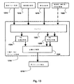
したがって、図1に示されるように、本技術の実施形態は、1つ又は複数のプロセッサ
を有して、本明細書において更に詳細に説明するアルゴリズム等の特定の漏れ検出方法論
を実施することができるコントローラ104を有する漏れ検出デバイス102又は装置を
含むことができる。したがって、デバイス又は装置は、集積チップ、メモリ、及び/又は
他の制御命令、データ、若しくは情報記憶媒体を含むことができる。例えば、そのような
検出方法論を包含したプログラム命令をデバイス又は装置のメモリ内の集積チップに符号
化して、特定用途向け集積チップ(ASIC)を形成することができる。そのような命令
は、追加又は代替として、適切なデータ記憶媒体を用いてソフトウェア又はファームウェ
アとしてロードすることができる。そのようなコントローラ又はプロセッサにより、デバ
イスを用いてフロー信号からのデータを処理することができる。
Thus, as shown in FIG. 1, embodiments of the present technology may have one or more processors to implement a particular leak detection methodology, such as the algorithms described in more detail herein. A
このため、プロセッサは、以前の睡眠セッションからの測定及び記録された呼吸フロー
データに基づいて、本明細書において、より詳細に論考される実施形態において説明され
るように、漏れを検出し、異なるタイプの漏れ間を識別若しくは区別し、及び/又は、漏
れ時間、持続時間、及び深刻度を求めること等によって、漏れの評価を制御することがで
きる。代替的に、検出は、呼吸フロー信号の測定と同時に、睡眠セッション中に実行する
ことができる。したがって、幾つかの実施形態では、デバイス又は装置自体を、オプショ
ンで、実施される方法論と併用される呼吸フロー信号を測定するフローセンサ106で実
施することができる。例えば、鼻カニューラ108若しくは鼻マスク若しくはフルフェー
スマスクへのフロー、又は鼻カニューラ108若しくは鼻マスク若しくはフルフェースマ
スクを通るフローは、呼吸気流計及び差圧変換器、又は1束の管若しくは導管を利用して
フロー信号を導出する装置のような同様の装置を用いて測定することができる。オプショ
ンで、フロー信号は、2005年11月2日に出願されたPCT/AU2005/001
688号に記載されるモータ電流センサ等の他のセンサから推測することができる。この
出願の開示全体は、相互参照によって引用することにより、本明細書の一部を成すものと
する。
Thus, the processor detects leaks based on measurements and recorded respiratory flow data from previous sleep sessions, as described in embodiments discussed in more detail herein, and detects Leak evaluation can be controlled, such as by identifying or distinguishing between types of leaks, and / or determining leak time, duration, and severity. Alternatively, the detection can be performed during a sleep session, simultaneously with the measurement of the respiratory flow signal. Thus, in some embodiments, the device or apparatus itself can be implemented with a
688 can be inferred from other sensors, such as a motor current sensor. The entire disclosure of this application is hereby incorporated by reference.
図1に更に詳細に示すように、漏れデバイス102は、漏れ検出デバイス102によっ
て記憶又は出力することができる漏れ報告において、図示される漏れ事象データ109等
の漏れ関連データを累積又は生成するように実施することができる。本明細書において、
より詳細に論考されるように、この出力は、デバイスのディスプレイ上に視覚的に出力す
ることもできるし、例えば無線で別の装置に電子的に転送することもできる。更なる例と
して、漏れ検出デバイスは、漏れ検出方法論に基づいて呼吸治療を提供するための制御方
法論とともに実施することができ、それによってデバイスは呼吸治療装置としての役割を
果たすことができる。例えば、図1に示すように、漏れ検出デバイス102はオプション
で、そのような制御に適したセンサ(例えば圧力センサ)を有するサーボ制御されたブロ
ワ等のフロー生成器110を有して実装することもできる。このため、CPAP治療と関
連付けられた治療圧力レベル等の呼吸治療計画又は圧力治療計画を、デバイスのコントロ
ーラによって送達することができる。オプションで、治療は、患者の各呼吸サイクルにわ
たって比較的一定に圧力を提供することもできるし、呼気中に、より低い圧力を提供し、
吸気中に、より高い圧力を提供するように調整することもできる。治療圧力レベルは、漏
れ補正された呼吸気流信号から求められたOSA事象(例えば無呼吸事象及び減呼吸事象
等)の検出に応じて自動的に調整することができる。オプションで、漏れ事象又は大量の
或る漏れ事象の検出を用いて、基準圧が逸脱しているか否かを判断することができる。こ
のため、これらの測定値を、基準圧への調整の基礎又はトリガとして用いることができる
。代替的に、重大な漏れ事象の検出は、OSA事象の自動検出又は治療圧力レベルの自動
変更の無効化を制御する役割を果たすことができる。他の圧力調整方式も実施することが
できる。また更に、重大な漏れ事象の検出は、コントローラが圧力治療の送達を無効にす
るか又は中断する条件としての役割を果たすことができる。
As shown in further detail in FIG. 1, the
As discussed in more detail, this output can be output visually on the display of the device, or can be electronically transferred, for example, wirelessly to another device. As a further example, a leak detection device can be implemented with a control methodology for providing respiratory therapy based on the leak detection methodology, whereby the device can act as a respiratory therapy device. For example, as shown in FIG. 1, the
It can also be adjusted to provide higher pressure during inspiration. The treatment pressure level can be automatically adjusted in response to detection of OSA events (eg, apnea events and hypopnea events, etc.) determined from the leak corrected respiratory airflow signals. Optionally, detection of a leak event or a large number of certain leak events can be used to determine if the baseline pressure has been deviated. Thus, these measurements can be used as a basis or trigger for adjustment to a reference pressure. Alternatively, the detection of a critical leak event can serve to control the automatic detection of OSA events or disabling automatic changes in treatment pressure levels. Other pressure regulation schemes can also be implemented. Still further, detection of a significant leak event can serve as a condition for the controller to disable or interrupt delivery of pressure therapy.
例えば、幾つかの実施形態では、連続口漏れ事象の検出等の漏れ事象の検出は、減呼吸
検出器の一部としての役割を果たすことができる。幾つかの自動化された減呼吸検出デバ
イスでは、口漏れは、誤検出減呼吸の意味で、減呼吸検出器の自動化された方法論によっ
て減呼吸事象として誤ってスコアリグされる場合がある。本明細書において記載する方法
により、減呼吸事象と同時の漏れ事象の検出を、検出された減呼吸のスコアリングを防ぐ
基準として用いることができる。例えば、呼吸において自動的に検出された減呼吸事象の
スコアリングは、その呼吸において検出された漏れ事象がないことの確認を条件とするこ
とができる。
For example, in some embodiments, detection of a leak event, such as detection of a continuous mouth leak event, can serve as part of a hypopnea detector. In some automated hypopnea detection devices, mouth leaks may be incorrectly scored as hypopnea events by the automated methodology of the hypopnea detector in the sense of falsely detected hypopnea. With the methods described herein, detection of a leak event concurrent with a hypopnea event can be used as a criterion to prevent scoring of the detected hypopnea. For example, scoring of automatically detected hypopnea events in a breath may be contingent on confirming that there are no leak events detected in the breath.
例示的な検出可能な漏れ事象に関して、鼻CPAP治療等の呼吸治療処置中に、複数の
異なる形で口漏れが生じる場合がある。これらの漏れ事象は、患者フローにおいて、又は
フローセンサからの患者フローを表すフロー信号において異なる形で表れる場合がある。
例えば、漏れは連続口漏れを示す場合がある。代替的に、漏れは弁状口漏れを示す場合が
ある。
For an exemplary detectable leak event, a mouth leak may occur in a number of different ways during a respiratory treatment procedure, such as nasal CPAP therapy. These leak events may appear differently in the patient flow or in the flow signal representing the patient flow from the flow sensor.
For example, a leak may indicate a continuous mouth leak. Alternatively, the leak may indicate a valve-like mouth leak.
連続口漏れ(「CML」)の間、患者の口は、少なくとも漏れが発生する各呼吸の実質
的にほとんど又は全体の間の意味で、連続して開いたままになっている。通常、この漏れ
によって、鼻で吸入された空気のうちの幾らかが、漏れが関与する各呼吸の持続時間にわ
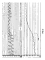
たって口から漏れ出すことになる。そのような事象は、図2のグラフにおいて示された信
号トレースにおいて表わされる。
During a continuous mouth leak ("CML"), the patient's mouth remains open, at least in the sense of substantially most or all of each breath in which the leak occurs. Normally, this leak will cause some of the nasal inhaled air to leak out of the mouth for the duration of each breath in which the leak is involved. Such an event is represented in the signal trace shown in the graph of FIG.
これに関して、図2は、信号トレースの上側のグラフと信号トレースの下側のグラフと
を含み、それらのグラフの双方が共通のタイムスケール上にある。上側の信号トレースは
フローの測定値を示している。下側のトレースは漏れ測定値であり、この事例では、相互
参照によりその開示の全体が本明細書の一部をなすものとする米国特許第6,659,1
01に記載されている瞬時漏れ等の瞬時漏れである。グラフは、フロー信号において表わ
されるような、漏れ測定値の変化(例えば増加)と換気量の変化(例えば低減)との間の
時間に基づく対応を示している。そのような同時変化の検出は、本技術の幾つかの実施形
態において、連続口漏れすなわちCMLの発生を示すものとみなすことができる。
In this regard, FIG. 2 includes a graph above the signal trace and a graph below the signal trace, both of which are on a common time scale. The upper signal trace shows the flow measurement. The lower trace is a leak measurement, in this case US Pat. No. 6,659,1 which is hereby incorporated by reference in its entirety.
No. 01 is an instantaneous leak such as an instantaneous leak. The graph shows a time-based correspondence between a change in leak measurement (eg, increase) and a change in ventilation (eg, decrease), as represented in the flow signal. Detection of such a simultaneous change may be considered as an indication of a continuous mouth leak or the occurrence of CML, in some embodiments of the present technology.
弁状口漏れ(「VML」)の間、鼻を通して吸入された空気は、呼吸周期の一部の間に
口を介して部分的に又は完全に吐き出される。通常、鼻からの吐き出しが正常に開始する
が、口が(弁のように)「パッと(pop)」開き、口からの吐き出しが可能になると、急
速に0まで下降する。これは、鼻フロー信号における鋭い負のピーク等の、フロー信号に
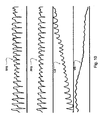
おける検出可能な変化として現れる可能性がある。そのような事象の例は、図3のグラフ
の信号トレースにおいて示されている。
During a valve-like mouth leak ("VML"), air inhaled through the nose is partially or completely exhaled through the mouth during a portion of the breathing cycle. Normally, exhalation from the nose starts normally, but falls rapidly to zero when the mouth opens (like a valve) "pop" and exhalation from the mouth becomes possible. This can manifest itself as a detectable change in the flow signal, such as a sharp negative peak in the nasal flow signal. An example of such an event is shown in the signal trace of the graph of FIG.
これに関して、図3は共通のタイムスケール上で信号トレースの上側のグラフと信号ト
レースの下側のグラフとを含む。上側の信号トレースは鼻フローの測定値を示している。
下側のトレースは瞬時漏れ測定値である。本技術の幾つかの実施形態では、フロー信号に
おけるそのような鋭い負のピークの検出は、弁状口漏れすなわちVMLの発生を示すもの
とみなすことができる。下側のトレースに示されるように、この検出可能な変化も瞬時漏
れ測定値の同時変化と対応することができる。
In this regard, FIG. 3 includes a graph above the signal trace and a graph below the signal trace on a common time scale. The upper signal trace shows a measurement of nasal flow.
The lower trace is the instantaneous leak measurement. In some embodiments of the present technology, the detection of such a sharp negative peak in the flow signal may be considered indicative of a valve-like mouth leak or the occurrence of VML. As shown in the lower trace, this detectable change can also correspond to a simultaneous change in instantaneous leak measurements.
このため、図1に更に示されるように、漏れ検出デバイス102は、CML事象及び/
又はVML事象並びにそのような事象に関する追加データ等の漏れ事象データ109を検
出し報告することができる。例えば、漏れ検出デバイス102は、1つ又は複数の睡眠セ
ッションの経過にわたってそのような検出された事象を区別し、それらの事象のカウント
を報告することができる。検出器は各漏れ事象の持続時間及び各事象が発生した時刻を求
めることができる。検出器は、そのような漏れが発生しなかったセッション時間を報告す
ることができる。検出器は、漏れ事象の分類(break down)を、漏れ事象全体に占めるパ
ーセンテージに基づいて更に報告することができる。検出器は、漏れ事象の持続時間の分
類を、睡眠セッション若しくは治療セッションの総持続時間又は漏れ時間の総持続時間に
占めるそれらの漏れ事象のパーセンテージに基づいて更に求めることができる。漏れ検出
デバイス102は、漏れの深刻度を要約する漏れインデックスも求めることができる。本
明細書において、より詳細に論考するように、このインデックスは、1つ又は複数の異な
るタイプの検出された漏れに関する情報を結合することができる。検出器は、そのような
深刻度インデックスに基づくことができる漏れ深刻度に関するメッセージ警告を更に実施
することができる。
To this end, as further shown in FIG. 1, the
Alternatively,
例えば、図4に示すように、幾つかの実施形態では、漏れ検出デバイス102は、プロ
セッサを制御して、呼吸可能なガスの測定フローから漏れを検出する方法を実施すること
ができる。440において、プロセッサの方法は、呼吸可能なガスの測定フローから複数
の特徴を求めることを含むことができる。例えば、幾つかの実施形態では、この方法は、
一回換気量等の換気量測定値を検出することができる。換気量測定値は、分時換気量(例
えば、0.5分から5分まで、好ましくは3分までの範囲の期間にわたって求められる測
定値)とすることができる。オプションで、そのような換気量測定値は、フロー信号から
時間期間(例えば0.5分、1分、3分、5分)にわたって取得したフローサンプルの絶
対値の和を二等分することによって求めることができる。そのような換気量測定量は、所
望の期間(例えば、0.5分、1分、3分、又は5分)にわたる患者フロー(患者フロー
が瞬時漏れ及びホース落下の補償を考慮することに起因する)の絶対値の半分の積分とし
て求めることもできる。またさらに、そのような換気量は、数分(例えば0.5分、1分
、3分、又は5分)、好ましくは3分の時定数で患者フローの絶対値の半分を低域通過フ
ィルタリングすることによって求めることができる。またさらに、測定値は、上記で言及
したような漏れ測定値又は瞬時漏れ測定値とすることができる。更なる例として、測定値
は、フロー信号のピークフロー値すなわち最大フロー値、又はフロー信号の他の検出可能
なアーチファクトとすることができる。442において、検出器は複数の特徴の解析を制
御して、それらの複数の特徴に基づいて漏れ事象を確定する。次に、検出器は、複数の異
なるタイプの漏れから漏れ事象の区分けを制御することができる。このようにして、検出
器は異なる漏れ持続時間又は漏れ量を単に検出するのではなく、異なるタイプの漏れを区
別することができる。例えば、幾つかの実施形態では、検出器はCML漏れ事象とVML
漏れ事象とを識別することができる。
For example, as shown in FIG. 4, in some embodiments, the
Ventilation measurements, such as tidal volume, can be detected. The ventilation measurement may be a minute ventilation (eg, a measurement determined over a period ranging from 0.5 minutes to 5 minutes, preferably 3 minutes). Optionally, such a ventilation measurement is obtained by bisecting the sum of the absolute values of the flow samples taken from the flow signal over a time period (eg, 0.5, 1, 3, 5 minutes). You can ask. Such ventilation measurements may be due to patient flow (e.g., patient flow taking into account momentary leaks and hose fall compensation) over a desired period of time (e.g., 0.5, 1, 3, or 5 minutes) ) Can be obtained as an integral of half of the absolute value of Still further, such ventilation may be a low-pass filtering of half the absolute value of the patient flow with a time constant of a few minutes (eg, 0.5, 1, 3, or 5 minutes), preferably 3 minutes. It can be obtained by doing. Still further, the measurements may be leak measurements or instantaneous leak measurements as mentioned above. As a further example, the measurement may be a peak or maximum flow value of the flow signal, or other detectable artifact of the flow signal. At 442, the detector controls the analysis of the plurality of features to determine a leak event based on the plurality of features. The detector can then control the separation of leak events from a plurality of different types of leaks. In this way, the detector can distinguish between different types of leaks, rather than simply detecting different leak durations or amounts. For example, in some embodiments, the detector may include a CML leak event and a VML
Leakage events can be distinguished.
A.例示的なCML漏れ事象検出の実施形態
CMLタイプの漏れ事象の検出のために実施することができる例示的な方法論を図5〜
図7を参照して検討することができる。例えば、図5に示すように、1つのそのような実
施形態では、540において、検出器のプロセッサは、呼吸可能なガスの測定フローから
換気量測定値及び漏れ測定値を求めることができる。次に、542において、プロセッサ
は換気量測定値及び漏れ測定値を解析して、換気量測定値及び漏れ測定値の同時変化を検
出することができる。次に、544において、プロセッサは同時変化に基づいて漏れ事象
を特定することができる。そのような同時変化は、例えば、漏れの増加に伴う換気量の減
少、又は漏れの減少に伴う換気量の増加とすることができる。
A. Exemplary CML Leakage Event Detection Embodiment Exemplary methodologies that can be implemented for CML type leak event detection are shown in FIGS.
This can be considered with reference to FIG. For example, as shown in FIG. 5, in one such embodiment, at 540, the processor of the detector may determine ventilation and leak measurements from the measured flow of breathable gas. Next, at 542, the processor can analyze the ventilation and leak measurements to detect a simultaneous change in the ventilation and leak measurements. Next, at 544, the processor can identify a leak event based on the concurrent change. Such a simultaneous change may be, for example, a decrease in ventilation with increasing leakage, or an increase in ventilation with decreasing leakage.
オプションで、そのようなプロセスは共分散を求めることに基づくことができる。その
ような一実施形態では、共分散は以下の漏れ検出器102の自動化された解析及び計算を
用いて求めることができる。そのような一実施形態の場合、入力データを処理することが
できる。この入力は、分時換気量測定値(例えば1分、3分、5分等)からサンプリング
された換気量値、漏れ測定値からサンプリングされた瞬時漏れ値、及びフィルタリングさ
れたフロー信号等のフロー信号からサンプリングされた患者フロー値を含むことができる
。オプションで、このデータはバッファリングすることができる。例えば、フロー値は呼
吸単位でバッファリングすることができる。このため、漏れ検出器への入力モジュールは
、現在の入力値(例えば換気量サンプル及び漏れサンプル、並びに現在の呼吸を表すフロ
ー値を有する入力ベクトル)を記憶することができる。そのような換気プロセス、漏れプ
ロセス、呼吸検出プロセス、及び共分散プロセスは、オプションで以下のように行うこと
ができる。
Optionally, such a process can be based on determining the covariance. In one such embodiment, the covariance may be determined using the following automated analysis and calculation of the
(1)換気量の求値
フロー値を処理して、分時換気量値(例えば3分時換気量(three minute ventilation
))を求めることができる。この分時換気量値は、オプションで、平滑化された換気量値
とすることもできる。例えば、フロー信号からのサンプルが得られ、そしてこのサンプル
が処理されて現在の平滑化された換気量値が求められる。本明細書において、より詳細に
論考するように、この値は患者フローベクトルにも適用される。換気量を求めるプロセス
は、以下のように行うことができる。
(a)患者フロー値Qpが得られる。
(b)次に、理想低域通過フィルタ等の低域通過フィルタを用いて、平滑化された換気
量を求める(正:be determined)ことができる。これは以下の式によって管理すること
ができる.

vnは瞬時分時換気量であり、例えば
aは換気量時定数(τ)(例えば30又は60)及びサンプリング時間(Δt)に従っ
て以下の式によって求めることができる。
は約30秒とすることができることが好ましい。
(1) Calculating the ventilation volume The flow value is processed and the minute ventilation value (for example, three minute ventilation (three minute ventilation)
)). The minute ventilation value may optionally be a smoothed ventilation value. For example, a sample from the flow signal is obtained and the sample is processed to determine a current smoothed ventilation value. This value also applies to the patient flow vector, as discussed in more detail herein. The process for determining ventilation can be performed as follows.
(A) the patient flow value Q p is obtained.
(B) Next, using a low-pass filter such as an ideal low-pass filter, a smoothed ventilation amount can be determined (correct: be determined). This can be managed by the following equation:
v n is the instantaneous minute volume, for example
a can be obtained by the following equation according to the ventilation time constant (τ) (for example, 30 or 60) and the sampling time (Δt).
平滑化された換気量を求めるプロセスは、3分時換気量又は5分時換気量を計算するプ
ロセスと同じとすることができるが、異なる時定数を実施することもできる。
The process of determining the smoothed ventilation may be the same as the process of calculating the 3 minute ventilation or the 5 minute ventilation, but different time constants may be implemented.
オプションで、幾つかの実施形態では、換気量測定値処理は、換気量測定値における覚
醒と関連付けられた呼吸の影響を最小限にするために、覚醒検出に基づくこともできる。
大きな覚醒が換気量測定値に影響を及ぼすことが許される場合、その覚醒に続く換気量が
減少することになる。そのような影響を回避するために、換気量測定値は、「覚醒のない
」換気量測定値に変更することができる。例えば、(例えば以下で論考する「覚醒フラグ
」に基づいて)覚醒が検出されると、正常な呼吸が再開するまで、(例えば以下のように
過去の換気量値を現在の換気量値に設定する、すなわち
If a large arousal is allowed to affect ventilation measurements, the ventilation following that awakening will be reduced. To avoid such effects, the ventilation measurements can be changed to "non-awake" ventilation measurements. For example, if arousal is detected (e.g., based on an "awakening flag" discussed below), until a normal breathing resumes (e.g., setting a past ventilation value to a current ventilation value as follows) Do, ie
そのような場合、覚醒検出器は以下のように実施することができる。
各呼吸の後、
(1)最も近時の呼吸のピークツーピークフロー(例えば最大フローから最小フローを
減算したもの)を測定する。
(2)この値が、最も近時の複数の呼吸(例えば最も近時の20回の呼吸)の平均ピー
クツーピークフローよりも或る係数(例えば1.5倍)大きい場合、覚醒とみなされる。
(3)最も近時の呼吸が覚醒であるとき、「覚醒フラグ」が設定され、フラグがリセッ
トされるまで換気量測定が値を無視することができるようにする。
他の覚醒検出方法論も実施することができる。
In such a case, the awakening detector can be implemented as follows.
After each breath
(1) Measure the most recent respiratory peak-to-peak flow (eg, the maximum flow minus the minimum flow).
(2) If this value is a factor (eg, 1.5 times) greater than the average peak-to-peak flow of the most recent breaths (eg, the last 20 breaths), it is considered awake .
(3) When the most recent breath is awake, an "awakening flag" is set so that the ventilation measurement can ignore the value until the flag is reset.
Other alertness detection methodologies can be implemented.
(2)漏れの求値
瞬時漏れ値をフィルタリングする。例えば、入力値を理想低域通過フィルタによって経
時的に平滑化する。これは以下の式によって管理することができる。
Xnは現在測定されている瞬時漏れである。
aは時定数(τ)(例えば20)及びサンプリング時間(Δt)に従って以下の式によ
って求めることができる。
60秒とすることができることが好ましい。
(2) Calculating the leak value The instantaneous leak value is filtered. For example, the input value is smoothed over time by an ideal low-pass filter. This can be managed by the following equation.
Xn is the instantaneous leak currently being measured.
a can be obtained by the following equation according to the time constant (τ) (for example, 20) and the sampling time (Δt).
(3)呼吸バッファ
患者フロー値を呼吸ベクトル又は他のデータ構造に加え、それによってデータを記憶す
る。このデータ構造、ベクトル、又はバッファは後に、呼吸単位の解析を実施することが
できる本明細書に記載される判定に用いることができる。このバッファは新たな呼吸ごと
に消去することができる。このため、データ構造を用いて、フローデータを、各吸気開始
又は呼気終了の検出の関数として集めることができる。
(3) Respiration buffer Add patient flow values to a respiration vector or other data structure, and thereby store data. This data structure, vector, or buffer can later be used in the determinations described herein that can perform a respiratory unit analysis. This buffer can be cleared with each new breath. Thus, using a data structure, flow data can be collected as a function of detecting each inspiration start or expiration end.
オプションで、次に、これらの漏れ入力値及び換気量入力値を、例えば選択された時間
期間(例えば、約20秒又は約30秒等の20秒〜120秒の範囲等の数秒程度)の平滑
された漏れ値を有する循環バッファ、及び選択された時間期間(例えば、約20秒又は約
30秒等の20秒〜120秒の範囲等の数秒程度)の換気量値を有する循環バッファとし
て更にバッファリングすることができる。このため、これらの信号バッファは、最も近時
の20秒、30秒、又は60秒の値等の最も近時の換気量値及び平滑化された漏れ値の記
録を維持することができる。
Optionally, these leak and ventilation inputs are then smoothed, for example, for a selected time period (eg, on the order of a few seconds, such as in the range of 20 seconds to 120 seconds, such as about 20 seconds or about 30 seconds). Buffer as a circulating buffer having a determined leak value and a circulating buffer having a ventilation value for a selected time period (eg, on the order of a few seconds, such as in the range of 20 seconds to 120 seconds, such as about 20 seconds or about 30 seconds). Can be ring. As such, these signal buffers can maintain a record of the most recent ventilation values and smoothed leak values, such as the most recent 20 seconds, 30 seconds, or 60 seconds values.
(4)共分散の求値
次に、循環バッファの換気量データ及び漏れデータに基づいて共分散特徴Cを計算する
ことができる。そのような共分散特徴Cを検討することができるが、この共分散特徴は2
つの信号の共分散と同一である必要はない。信号共分散は、2つの変数がどれだけ密接に
ともに増減するかの測定値とみなすことができる。高い正の共分散は、双方がともに強く
動いていることを示す一方、高い負の共分散はそれらが逆に動いている(すなわち、一方
が増大し、他方が減少する)ことを示す。
(4) Determination of Covariance Next, the covariance feature C can be calculated based on the ventilation data and the leakage data of the circulation buffer. One can consider such a covariance feature C, but this covariance feature is 2
It need not be the same as the covariance of the two signals. Signal covariance can be viewed as a measure of how closely two variables increase or decrease together. A high positive covariance indicates that both are moving strongly, while a high negative covariance indicates that they are moving in reverse (ie, one increases and the other decreases).
このため、[(v={v)]1,v2,...,vn}で示すことができる換気量バッ
ファ及び[(l={l)]1,l2,...,ln}で示すことができる漏れバッファは
、以下のプロセスによって解析することができる。
(1)第1に、換気量及び漏れの共分散(cov)を以下の式を用いて計算することが
できる。
できる。このステップは、負の共分散(例えば、(1)換気量が減少し漏れが増大すると
き、これは連続口漏れ事象の開始を示すものとみなすことができる、又は(2)換気量が
増大し漏れが減少するとき、これは連続口漏れ事象の終了を示すものとみなすことができ
る)に焦点を当てることが望ましい場合に実行することができる。このため、このステッ
プは、正の共分散を無視するように実施することができる。
(3)オプションで、この共分散値に、漏れバッファの勾配の正負符号又は正負符号関
数を乗算することもできる。これによって、漏れ事象の開始(漏れ増加)と終了(漏れ減
少)との間の識別を可能にすることができる。オプションで、アルゴリズムの実行時間を
最低限にするために、漏れバッファに沿って均等に配置された値のうちの幾つかのみ(例
えば10個の点)を用いることによって、勾配演算を推定値として単純化することができ
る。例えば、勾配は、以下の式を用いて得ることができる。
(1) First, the ventilation and leak covariance (cov) can be calculated using the following equation:
(3) Optionally, this covariance value can be multiplied by a sign or sign function of the gradient of the leaky buffer. This may allow for discrimination between the start (leak increase) and end (leak decrease) of a leak event. Optionally, to minimize the execution time of the algorithm, use only some of the values (e.g., 10 points) evenly distributed along the leak buffer to make the gradient operation an estimate. Can be simplified. For example, the gradient can be obtained using the following equation:
このため、例示的な実施形態では、最終共分散特徴値Cを、以下の式を用いて求めるこ
とができる。
次に、共分散特徴を経時的に累積することができる。例えば、共分散特徴C値を経時的
に合算又は積分して、累積された共分散特徴ACを形成することができる。例えば、プロ
セッサは共分散特徴Cを積分し、それによって共分散特徴Cによって表わされる曲線下の
面積を、経時的に変化するのに合わせて求めることができる。このステップは時間依存性
を最小限にするのに望ましい。例えば、図6に示すように、共分散特徴Cはそれ自体では
常に大きいとは限らず、長い時間期間にわたって中程度で維持されている場合がある。図
6では、漏れ事象を含むフロー信号F、換気量測定値V、瞬時漏れ測定値L、共分散特徴
C、及び累積された共分散特徴ACの信号トレースが共通時間軸上にプロットされている
。
The covariance features can then be accumulated over time. For example, the covariance feature C values can be summed or integrated over time to form an accumulated covariance feature AC. For example, the processor can integrate the covariance feature C, thereby determining the area under the curve represented by the covariance feature C as it changes over time. This step is desirable to minimize time dependence. For example, as shown in FIG. 6, the covariance feature C is not always large by itself and may be maintained at a moderate level over a long period of time. In FIG. 6, signal traces of a flow signal F including a leak event, a ventilation measurement V, an instantaneous leak measurement L, a covariance feature C, and an accumulated covariance feature AC are plotted on a common time axis. .
幾つかの実施形態では、累積された共分散特徴ACは、自動化されたプロセスにおいて
以下のように計算することができる。
(1)AC=0の特徴値で開始する。
(2)求められた共分散特徴Cの値ごとに、以下の式を用いて累積された共分散特徴A
Cを更新する。
変化しないことを確実にする乗数である。
(3)Cの最後の値が異なる正負符号であるか又はゼロに等しい場合、累積された共分
散特徴ACは、何らかの新たな値を加える前にゼロにリセットされる。
In some embodiments, the accumulated covariance feature AC can be calculated in an automated process as follows.
(1) Start with a feature value of AC = 0.
(2) For each value of the obtained covariance feature C, the covariance feature A accumulated using the following equation
Update C.
(3) If the last value of C is a different sign or equal to zero, the accumulated covariance feature AC is reset to zero before adding any new values.
このようにして、累積された共分散特徴ACの値は、連続共分散の大きさを1方向(例
えば漏れ増加又は漏れ減少)に追跡する。
In this way, the value of the accumulated covariance feature AC tracks the magnitude of the continuous covariance in one direction (eg, leak increase or leak decrease).
オプションで、幾つかの実施形態では、累積された共分散信号は、様々な追加条件に基
づいて(例えばゼロに)リセットすることができる。本質的に、これらは、マスクの適合
、圧力調整等の逆の効果によって、漏れ値及び換気量値が、漏れ検出プロセスにおいて依
拠される前に安定化することを確実にするように設計される。
Optionally, in some embodiments, the accumulated covariance signal can be reset (eg, to zero) based on various additional conditions. Essentially, they are designed to ensure that leak and ventilation values stabilize before being relied on in the leak detection process due to the opposite effects of mask fitting, pressure adjustment, etc. .
例えば、検出器の幾つかの実施形態において以下の条件を実装することができる。 For example, the following conditions may be implemented in some embodiments of the detector.
(a)最も近時の10回の呼吸のうちの5回よりも多くの呼吸が弁状口漏れを有した。
このような条件は、長期にわたるVML事象によって、換気量測定値が著しく減少したこ
とを示すものとみなすことができる。これは、VML事象の深刻な事例において発生する
可能性がある。検出器は、AC信号に基づいて、この事象をVML事象として正しく報告
するのではなく、CML事象として誤って報告する可能性がある。この条件はそのような
誤検出を回避するのに役立つことができる。
(A) More than 5 of the 10 most recent breaths had valve-like mouth leaks.
Such a condition can be considered to indicate that a prolonged VML event has significantly reduced ventilation measurements. This can occur in severe cases of VML events. The detector may incorrectly report this event as a CML event based on the AC signal, rather than correctly reporting this event as a VML event. This condition can help avoid such false positives.
(b)SmartStart/SmartStop特徴がアクティベートされるとき。
Smartstartは、呼吸治療装置が、患者がマスクから又はマスクに対し呼吸して
いるのを検出すると自動的に圧力治療を開始することを可能にする特徴である。Smar
tstopは、このデバイスが、患者がマスクを取り外したことを検出すると、圧力治療
が自動的に停止することを可能にする。これらの検出は、マスクにおいて圧力の或る変化
を検出することに基づくことができる。そのような特徴が利用される事象において、AC
信号は、マスクの取り外しが検出されるか又は最初のマスク使用が検出されたときにゼロ
にリセットすることができる。そのようなAC信号の調整は、治療の開始中又は治療の停
止付近で発生する場合がある漏れ測定値又は換気量測定値の大きなスパイクをネゲートす
ることができる。これは、フローデータを評価して特定の時間期間(例えば2分)にわた
って「長い呼吸」を検出することによって検出することができる。オプションで、AC特
徴は、使用時間の初期期間中(例えば、1分から4分の範囲の期間であり、呼吸時間の最
初の約2分の期間であることが好ましい)にゼロに維持することができる。
(B) When the SmartStart / SmartStop feature is activated.
Smartstart is a feature that allows the respiratory therapy device to automatically initiate pressure therapy when it detects that the patient is breathing from or against the mask. Smar
tstop allows the pressure treatment to stop automatically when the device detects that the patient has removed the mask. These detections can be based on detecting certain changes in pressure at the mask. In the event that such a feature is used, AC
The signal can be reset to zero when mask removal is detected or when initial mask use is detected. Adjustment of such an AC signal may negate large spikes in leak or ventilation measurements that may occur during or near the end of treatment. This can be detected by evaluating the flow data to detect "long breaths" over a specific time period (eg, 2 minutes). Optionally, the AC feature may be maintained at zero during an initial period of use (eg, a period in the range of 1 minute to 4 minutes, preferably the first approximately 2 minutes of breathing time). it can.
(c)漏れが特定のレベルに達したとき。
漏れバッファの瞬時漏れ測定値の漏れ値が或る閾値を超えた(例えば1.5L/min
を超えた)とき、累積された共分散特徴をリセットする(例えばゼロに設定する)ことが
できる。そのような大きな漏れ値は、検出プロセスに悪影響を及ぼす可能性があり、CM
L事象のインジケータとなる可能性が低い。実際に、そのような高い漏れは、CML以外
の何らかの故障のインジケータとなる可能性がより高い。
(C) When the leak reaches a certain level.
The leak value of the instantaneous leak measurement value of the leak buffer exceeds a certain threshold (for example, 1.5 L / min)
Is exceeded), the accumulated covariance feature can be reset (eg, set to zero). Such large leak values can adversely affect the detection process,
It is unlikely to be an indicator of an L event. In fact, such a high leak is more likely to be an indicator of some failure other than CML.
したがって、CML事象の検出の方法論は、累積された共分散特徴ACに基づくことが
できる。これは、AC特徴を1つ又は複数の閾値と1回又は複数回比較することを含むこ
とができる。これに関して、図6における累積された共分散AC信号トレースを、CML
事象が時刻T1において開始し、時刻T2において終了したことを示すものとみなすこと
ができる。これらの時刻の差は、CML事象の持続時間の測定値とみなすことができる。
T1及びT2がサンプル番号である場合、持続時間はサンプルカウントとすることができ
る。さらに、累積された共分散特徴ACの大きさは、CML事象の現在のステータスを定
量化するもの(quantifier)としての役割を果たすことができる。またさらに、ACの負
のピーク又はACの絶対値のピーク等の、所与のCML事象における累積された共分散特
徴ACのピーク値が、特定のCML事象を定量化する測定値としての役割を果たすことが
できる。更なる例として、CML事象を定量化するものは、CML事象検出と、漏れ又は
瞬時漏れ測定値とに基づくことができる。例えば、CML事象の特定の時間期間中の漏れ
測定値は、CML事象の量の測定値としての役割を果たすことができる。幾つかの実施形
態では、事象の開始時点から事象の停止時点までのそのような漏れ測定値の積分又は合算
は、そのような測定値としての役割を果たすことができる。
Thus, the methodology for detecting CML events can be based on the accumulated covariance features AC. This may include comparing the AC feature with one or more thresholds one or more times. In this regard, the accumulated covariance AC signal trace in FIG.
It can be considered that the event started at time T1 and ended at time T2. The difference between these times can be considered a measure of the duration of a CML event.
If T1 and T2 are sample numbers, the duration may be a sample count. Further, the magnitude of the accumulated covariance feature AC can serve as a quantifier for the current status of the CML event. Still further, the peak value of the accumulated covariance feature AC at a given CML event, such as the negative peak of AC or the peak of the absolute value of AC, serves as a measurement to quantify a particular CML event. Can be fulfilled. As a further example, those that quantify CML events may be based on CML event detection and leak or instantaneous leak measurements. For example, a leak measurement during a particular time period of a CML event can serve as a measure of the amount of the CML event. In some embodiments, the integration or summation of such leak measurements from the start of the event to the stop of the event can serve as such a measurement.
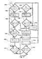
例示的な一実施形態では、累積された共分散ACを、図7のフローチャートの検出プロ
セス等のCML事象検出のためのアルゴリズムの一部として用いて、連続口漏れが存在す
るか否かを判断することができる。そのような実施形態では、変数(CML状態)を、累
積された共分散AC特徴に基づいて、CML事象が発生しているか否かを示すように設定
することができる。このプロセスは、累積された共分散AC特徴について新たな値が求め
られるごとに循環することができる。
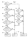
In one exemplary embodiment, the accumulated covariance AC is used as part of an algorithm for CML event detection, such as the detection process of the flowchart of FIG. 7, to determine whether continuous mouth leaks are present. can do. In such an embodiment, a variable (CML state) can be set to indicate whether a CML event has occurred based on the accumulated covariance AC characteristics. This process can cycle through each time a new value is determined for the accumulated covariance AC feature.
図7において、760において検出プロセスがCML状態変数の現在の状態を求める。
CML状態値がオンである(すなわちCML事象が進行中である)場合、フローは774
に進む。CML状態がオフである(すなわちCML事象がまだ進行中でない)場合、フロ
ーは762に進む。
In FIG. 7, at 760, the detection process determines the current state of the CML state variable.
If the CML state value is on (ie, a CML event is in progress), the flow is 774
Proceed to. If the CML state is off (ie, a CML event is not yet in progress), flow proceeds to 762.
762において、AC特徴が、機械学習プロセス等によって1人又は複数人の患者から
の既知のデータに基づいて経験的に求めることができる所定の閾値と比較される。例えば
、累積された共分散ACが開始閾値(例えば−0.19l2/s2)未満である場合、プ
ロセスは764に進むことができる。開始閾値未満でない場合、プロセスは772に進む
ことができ、772において、CML状態変数に対し状態変更が行われず、プロセスは次
のAC値について再開することができる。オプションで、この開始閾値は、約−0.13
3l2/s2等の、約−0.001l2/s2〜約−2.0l2/s2の範囲とすること
ができる。
At 762, the AC features are compared to a predetermined threshold that can be determined empirically based on known data from one or more patients, such as by a machine learning process. For example, if less than the accumulated covariance AC start threshold (e.g. -0.19l 2 / s 2), the process may proceed to 764. If not, the process can proceed to 772 where no state change is made to the CML state variable and the process can resume for the next AC value. Optionally, this starting threshold is about -0.13
Such 3l 2 / s 2, can be in the range of about -0.001l 2 / s 2 ~ about -2.0l 2 / s 2.
オプションで764において、呼吸ベクトルを検査して、現在の呼吸が、数分又は数秒
程度の時間期間(例えば約100秒〜140秒であるが、120秒であることが好ましい
)を超える呼吸等の長い呼吸であるか否かを判断することができる。現在の呼吸が「長い
」呼吸である場合、プロセスは722に進むことができ、722ではCML状態変数に対
し状態変更が行われず、図7の全体プロセスを次のAC値について再開することができる
。
Optionally, at 764, the respiratory vector is examined to determine if the current breath is over a time period on the order of minutes or seconds (e.g., about 100-140 seconds, but preferably 120 seconds). It is possible to determine whether or not the breath is long. If the current breath is a “long” breath, the process can proceed to 722 where no state change is made to the CML state variable and the entire process of FIG. 7 can be restarted for the next AC value .
オプションで、766において、タイマを検査して、最も近時の長い呼吸以来、バッフ
ァが埋まり、システムが再び完全に動作可能となることを可能にする時間期間が経過した
か否かを判断することができる。オプションで、時間期間は、長い呼吸を定義する時間期
間と同じか、又はほぼ同じとすることができる。例えば、時間期間は、約100秒〜約1
40秒の範囲をとることができるが、120秒であることが好ましい。タイマは通常、検
出された各長い呼吸の終了の検出時に始動される。時間期間が経過すると、フローは76
8に進む。時間期間が経過していない場合、プロセスは722に進むことができ、722
ではCML状態変数に対し状態変更が行われず、図7の全体プロセスを次のAC値につい
て再開することができる。
Optionally, at 766, check a timer to determine if a time period has elapsed since the most recent long breath, which allowed the buffer to fill and allow the system to become fully operational again. Can be. Optionally, the time period can be the same as or approximately the same as the time period defining the long breath. For example, the time period may be from about 100 seconds to about 1
The range can be 40 seconds, but is preferably 120 seconds. A timer is usually started upon detection of the end of each long breath detected. After the time period elapses, the flow is 76
Proceed to 8. If the time period has not elapsed, the process can proceed to 722, where 722
No state change is made to the CML state variable, and the entire process of FIG. 7 can be restarted for the next AC value.
オプションで、768において、前の事象のデータが検査され、幾つかの前の呼吸が弁
状漏れ(VML)事象を検出したか否かが判断される。例えば、直前の数回の呼吸(5回
〜15回の範囲であるが、10回が好ましい)のうち、これらの呼吸の幾つか(例えば半
分以下、5回等)がVML事象を有する。そのような事象が存在する場合、フローは77
0に進み、770において、CML状態変数がオンに設定され、検出されたCML事象の
開始又は存在を示す。存在しない場合、プロセスは772に進むことができ、772にお
いて、CML状態変数に対し状態変更が行われず、図7の全体プロセスを次のAC値につ
いて再開することができる。
Optionally, at 768, the data of the previous event is examined to determine if some previous breaths have detected a valve leak (VML) event. For example, of the last few breaths (ranging from 5 to 15 but preferably 10), some of these breaths (eg, less than half, 5 etc.) have a VML event. If such an event exists, the flow is 77
Proceeding to 0, at 770, the CML state variable is set on to indicate the start or presence of a detected CML event. If not, the process can proceed to 772 where no state change is made to the CML state variable and the entire process of FIG. 7 can be restarted for the next AC value.
774において、760におけるクエリへの正の応答の結果として、累積された共分散
特徴ACが別の所定の閾値と比較される。これは762の開始閾値と同じとすることもで
きるし、異なることもできる。これに関して、774においてこの閾値は、経験的な実験
又は解析によって同様に求めることができる停止閾値とみなすことができる。774の例
示的な比較では、AC特徴が停止閾値(例えば0.1l2/s2)を超えていない場合、
フローは776に進む。AC特徴が停止閾値を超えている場合、プロセスは780に進み
、780において、CML状態変数に対し状態変更が行われ、この変数はオフに設定され
、CML事象の終了を示す。オプションで、この停止閾値は、約+0.05l2/s2等
の、約0.001l2/s2〜約2.0l2/s2の範囲とすることができる。その後、
図7の全体プロセスを次のAC値について再開することができる。
At 774, the accumulated covariance feature AC is compared to another predetermined threshold as a result of a positive response to the query at 760. This can be the same as the start threshold of 762, or it can be different. In this regard, at 774 this threshold can be considered as a stop threshold, which can also be determined by empirical experimentation or analysis. In 774 an exemplary comparison, if the AC characteristic does not exceed the stop threshold value (e.g., 0.1l 2 / s 2),
The flow proceeds to 776. If the AC feature is above the stop threshold, the process proceeds to 780, where a state change is made to the CML state variable, which is set to off, indicating the end of the CML event. Optionally, the stop threshold may be about + 0.05 L, such as 2 / s 2, the range of about 0.001l 2 / s 2 ~ about 2.0l 2 / s 2. afterwards,
The entire process of FIG. 7 can be restarted for the next AC value.
776において、換気量を検査して、換気量測定値がCML前の検出値に戻ったか否か
を判断する。この判断は、換気量バッファの値と、770においてそのような換気量閾値
の設定等によってCML事象検出の開始時に設定された、前に記録された換気量値とに基
づくことができる。例えば、776において、換気量が現在のCML事象の開始時又は開
始前の量に戻っていない場合、フローは778に進む。換気量が戻っている場合、プロセ
スは780に進み、780において、CML状態変数に状態変更が行われ、この変数はオ
フに設定され、CML事象の終了を示す。その後、図7の全体プロセスを次のAC値につ
いて再開することができる。
At 776, the ventilation is inspected to determine whether the ventilation measurement has returned to the pre-CML detection value. This determination may be based on the value of the ventilation buffer and the previously recorded ventilation value set at the start of CML event detection, such as by setting such a ventilation threshold at 770. For example, at 776, if the ventilation has not returned to the volume at or before the start of the current CML event, flow proceeds to 778. If ventilation is returning, the process proceeds to 780 where a state change is made to the CML state variable, which is set to off, indicating the end of the CML event. Thereafter, the entire process of FIG. 7 can be restarted for the next AC value.
778において、検出器は、漏れ測定値が現在のCML事象の検出前のレベル又は量に
戻ったか否かを判断する。この判断は、漏れバッファの値と、770においてそのような
漏れ閾値の設定等によってCML事象検出の開始時に設定された、前に記録された漏れ値
とに基づくことができる。例えば、778において、漏れが現在のCML事象の開始時又
は開始前の量に戻っていない場合、フローは772に進む。772において、CML状態
変数に状態変更が行われず、図7の全体プロセスを次のAC値について再開することがで
きる。一方、778において漏れが戻っている場合、プロセスは780に進み、780に
おいて、CML状態変数に状態変更が行われ、この変数はオフに設定され、CML事象の
終了を示す。その後、図7の全体プロセスを次のAC値について再開することができる。
At 778, the detector determines whether the leak measurement has returned to the pre-detection level or amount of the current CML event. This determination can be based on the value of the leak buffer and the previously recorded leak value set at the start of CML event detection, such as by setting such a leak threshold at 770. For example, at 778, if the leak has not returned to the amount at or before the start of the current CML event, flow proceeds to 772. At 772, no state change is made to the CML state variable and the entire process of FIG. 7 can be restarted for the next AC value. On the other hand, if the leak returns at 778, the process proceeds to 780, where a state change is made to the CML state variable, which is set to off, indicating the end of the CML event. Thereafter, the entire process of FIG. 7 can be restarted for the next AC value.
そのようなプロセスが漏れ検出器102のプロセッサにおいて実施されると、CML事
象を検出することができる。一方、この例示的な実施形態において、検出漏れは誤検出よ
り好ましい。このために、連続口漏れCML事象の開始を検出するための判断基準は、C
ML事象の終了を検出するための判断基準よりも厳しい。
When such a process is implemented in the processor of the
Tighter than the criteria for detecting the end of an ML event.
実施形態では、上述したように、長い呼吸の測定値を試験することによって、(a)治
療デバイスが最初に始動されたときに、(b)マスクが患者の顔の上に配置される前に治
療デバイスが始動されたときに、又は(c)他の拡張した現象に起因して、換気量及び漏
れにおいて発生するスパイク等の事象がCML事象として誤って分類されないことを確実
にすることができる。
In embodiments, as described above, by testing long breath measurements, (a) when the treatment device is first activated, (b) before the mask is placed over the patient's face It can be ensured that events such as spikes that occur in ventilation and leaks are not misclassified as CML events when the treatment device is activated or (c) due to other expanded phenomena. .
776及び778において前に記録された開始値に対し漏れ測定値及び/又は換気量測
定値を試験することによって、不利な状況であってもCML事象の終了を検出することが
できることを確実にすることができる。例えば、幾つかの事例では、CML事象は漏れを
隠し続け、強い共分散が存在しない場合があるが、それにもかかわらず、検出器の説明さ
れたプロセスは依然としてCMLの終了を示すことができる。
Testing the leak and / or ventilation measurements against the starting values previously recorded at 776 and 778 ensures that the end of the CML event can be detected even in adverse situations. be able to. For example, in some cases, the CML event may continue to mask the leak and there may not be a strong covariance, but nonetheless, the described process of the detector may still indicate the end of the CML.
幾つかの実施形態では、漏れ及び換気量の開始値は、770におけるプロセスに基づい
て記録することができる。一方、これらの開始値は、現在のCML事象の開始の検出の直
前に、共分散特徴Cの正負符号が最後に変化したときに検出された相関期間の開始と時間
的に一致する換気量値及び漏れ値も指す場合がある。
In some embodiments, the starting values for leaks and ventilation may be recorded based on the process at 770. On the other hand, these start values are the ventilation values that coincide with the start of the correlation period detected when the sign of the covariance feature C last changed just before the start of the current CML event was detected. And leakage values.
幾つかの実施形態では、776及び778におけるプロセスの閾値比較は、漏れ及び換
気量の開始値、並びに換気量バッファ及び漏れバッファの平均値も含むことができる。例
えば、漏れ開始値(starting leak)は、漏れバッファの漏れ値の平均漏れ値と比較する
ことができ、換気量開始値(starting ventilation)は、換気量バッファの換気量値の平
均換気量値と比較することができる。例えば、換気量バッファの平均が換気量開始値より
も大きい場合、検出器は、CML事象が終了したことを示すことができる。更に、漏れバ
ッファの平均が漏れ開始値よりも低い場合、検出器はCML事象が終了したことを示すこ
とができる。
In some embodiments, the threshold comparisons of the process at 776 and 778 may also include leak and ventilation start values, as well as an average of the ventilation and leak buffers. For example, the leaking start value (starting leak) can be compared to the average leak value of the leak value of the leak buffer, and the ventilation start value (starting ventilation) can be compared with the average ventilation value of the ventilation value of the ventilation buffer. Can be compared. For example, if the average of the ventilation buffer is greater than the ventilation start value, the detector may indicate that the CML event has ended. Furthermore, if the average of the leak buffer is lower than the leak start value, the detector can indicate that the CML event has ended.
幾つかの実施形態では、768のプロセスにおいて実施されるように、弁状口漏れ事象
について直前の複数回の呼吸(例えば、好ましくは10回等の最も近時の5回〜15回の
範囲の呼吸における複数回の呼吸)をチェックすることが望ましい場合がある。深刻な場
合、長期にわたるVML事象によって、換気量が著しく低減する可能性がある。これは、
本来であれば代わりにCML事象として検出された場合がある。一方、768のプロセス
はこの問題を緩和することができる。
In some embodiments, as performed in the process of 768, multiple previous breaths (e.g., preferably in the range of the most recent 5 to 15 breaths, such as preferably 10 breaths) for a flap-like leak event. It may be desirable to check for multiple breaths in a breath). In severe cases, prolonged VML events can significantly reduce ventilation. this is,
Originally, it may have been detected as a CML event instead. On the other hand, the process of 768 can alleviate this problem.
図7Aは、累積された共分散ACに基づいてCMLを検出するための別の例示的な実施
形態を示している。このプロセスのこの方法論は、図7のプロセスに相当する。一方、図
7の764における長い呼吸のチェック、766における長い呼吸の経過チェック、及び
768の最も近時の数回の呼吸のチェックは省かれている。さらに、769における更な
るオプションのチェックが図7Aにおいて加えられる。769において、換気量測定値が
チェックされ、換気量測定値を閾値と比較すること等によって、換気量測定値が或る量を
超えて降下したか否かが判断される。閾値は、開始換気量値と関連付けることができる。
このため、潜在的なCML事象の開始が760において検出されると、プロセスは769
に進み、換気量が、760におけるチェックの前の換気量の或る率(例えば約85%)未
満まで降下する等、十分に降下したか否かを判断する。幾つかの場合、大量のマスク漏れ
及び少量の換気量変化が強い共分散を有する場合があるが、これは実際の連続口漏れ事象
の結果ではない。小さな換気量の変化は患者の呼吸パターンと関連付けることができる。
このため、このチェックは、換気量が十分に変化していない場合、CML事象の誤検出に
よるインジケーションを防ぐように実施することができる。本明細書には示されていない
が、そのようなチェックは、オプションで図7の例示的なプロセスに実装することもでき
る。
FIG. 7A illustrates another exemplary embodiment for detecting CML based on the accumulated covariance AC. This methodology of this process corresponds to the process of FIG. On the other hand, the long breath check at 764, the long breath progress check at 766, and the most recent several breath checks at 768 in FIG. 7 have been omitted. In addition, a further optional check at 769 is added in FIG. 7A. At 769, the ventilation measurements are checked and it is determined whether the ventilation measurements have dropped by more than a certain amount, such as by comparing the ventilation measurements to a threshold. The threshold can be associated with a starting ventilation value.
Thus, if the onset of a potential CML event is detected at 760, the process proceeds to 769
To determine if the ventilation has fallen sufficiently, such as to fall below a certain rate (eg, about 85%) of the ventilation before the check at 760. In some cases, large mask leaks and small ventilation changes may have strong covariance, but this is not the result of an actual continuous mouth leak event. Small changes in ventilation can be related to the patient's breathing pattern.
Therefore, this check can be performed so as to prevent an indication due to erroneous detection of a CML event when the ventilation volume has not sufficiently changed. Although not shown herein, such a check may optionally be implemented in the exemplary process of FIG.
図6と同様に、CML事象の検出と関連付けられた信号トレースの更なるグラフが図6
Aに示されている。一方、このバージョンでは、以前に説明された方法論のうちの任意の
ものによって設定することができるCML状態変数のステータス(図6AにおいてCML
−Sとして示される)を表すことができる追加の信号が示されている。フロー信号F、C
ML状態信号CML−S、漏れ信号L、換気量信号V、共分散信号C、及び累積された共
分散信号ACも共通時間軸上にプロットされる。CML事象は発生時刻(time occurrenc
e)T1と発生時刻T2との間の期間に発生するものとして示されている。
As in FIG. 6, a further graph of the signal trace associated with the detection of a CML event is shown in FIG.
A. However, in this version, the status of the CML state variable (CML in FIG. 6A) that can be set by any of the previously described methodologies
(Shown as -S) are shown. Flow signals F, C
The ML status signal CML-S, the leak signal L, the ventilation signal V, the covariance signal C, and the accumulated covariance signal AC are also plotted on a common time axis. CML events are generated at the time
e) It is shown as occurring during the period between T1 and occurrence time T2.
図6Aに示すように、CML事象の実際の発生時刻とその検出との間に遅延が存在する
場合がある。そのような遅延は、共分散を処理した結果である可能性があり、特に幾つか
の実施形態において実施される場合がある共分散バッファの時間長に起因する場合がある
。そのような遅延を補償するために、検出器の幾つかのバージョンが、CML状態変数を
非検出状態に設定するための更なる条件としての役割を果たすこともできるし、CML事
象の時刻を検出するのに利用することもできる共分散時間遅延(COV_DELAY)を
実装することができる。この遅延は図6Aに示されている。図面において、この遅延は点
D1(発生時刻T1においてCML事象が実際に開始したとき)と点D2(検出器が最初
に発生時刻T1−Dにおいて事象を検出したとき)との間に示されている。COV DE
LAY時間は、線D1−D2の期間として示されている。このため、幾つかの実施形態で
は、検出された事象の時間期間を求めることは、検出の時間遅延(例えばT1−DからT
1を減算したもの)と関連付けられたこの遅延時間によって調整することができる。例え
ば、この時間は、T2における事象の終了時に加算して、事象の総時間を検出することが
できる。代替的に、CML状態変数をオフに設定する方法(例えば図7Aのプロセス78
0)は、CML状態変数が発生時刻T2−Dにおいてオフに設定される前のCOV_DE
LAYの経過時間期間を用いてタイマを実行することを条件とすることができる。例えば
、タイマは図7Aのプロセス780に入るときに実行を開始することができ、CML状態
変数は、タイマがCOV DELAY時間期間経過したときにオフに設定することができ
る。
As shown in FIG. 6A, there may be a delay between the actual occurrence time of a CML event and its detection. Such a delay may be the result of processing the covariance, and may be due in particular to the length of time of the covariance buffer, which may be implemented in some embodiments. To compensate for such delays, some versions of the detector may serve as an additional condition to set the CML state variable to the undetected state, or to detect the time of the CML event. A covariance time delay (COV_DELAY) can also be implemented that can be used to This delay is shown in FIG. 6A. In the drawing, this delay is shown between point D1 (when the CML event actually starts at time T1) and point D2 (when the detector first detects the event at time T1-D). I have. COV DE
The LAY time is shown as the period of line D1-D2. Thus, in some embodiments, determining the time period of the detected event includes determining the time delay of the detection (eg, T1-D to T-D).
This delay time associated with (subtraction of 1) can be adjusted. For example, this time can be added at the end of the event at T2 to detect the total time of the event. Alternatively, a method of setting the CML state variable to off (eg, process 78 in FIG. 7A)
0) is COV_DE before the CML state variable is set off at the occurrence time T2-D.
The condition may be that the timer is executed using the elapsed time period of LAY. For example, the timer can begin execution when entering
B.例示的なVML漏れ事象検出の実施形態
VMLタイプの漏れ事象の検出のために実施することができる例示的な方法論を図8及
び図9を参照して検討することができる。幾つかの実施形態では、そのようなプロセスは
、患者フロー信号からのデータを解析して、通常の弁状口漏れを表すとみなすことができ
る、呼気中の負のピーク等の鋭い負のピークを検出することができる。1つのそのような
実施形態では、プロセスは、患者フローが呼気中の選択されたカットオフフローレベル未
満である(各呼吸における)持続時間を測定することができる。この持続時間が非常に短
いとみなされる場合、これは弁状口漏れが発生している可能性が高い鋭い負のピークであ
るとみなすことができる。
B. Exemplary VML Leakage Event Detection Embodiment An exemplary methodology that can be implemented for the detection of a VML-type leak event can be discussed with reference to FIGS. 8 and 9. In some embodiments, such a process involves analyzing data from the patient flow signal to determine a sharp negative peak, such as a negative peak during exhalation, that can be considered to represent normal valve-like mouth leakage. Can be detected. In one such embodiment, the process can measure the duration (at each breath) where the patient flow is below the selected cutoff flow level during expiration. If this duration is considered to be very short, it can be considered to be a sharp negative peak where a valve-like mouth leak is likely to occur.
例えば、図8に示すように、1つのそのような実施形態では、検出器のプロセッサは、
呼吸において閾値未満に下降するフローの測定値と関連付けられた第1の発生と、880
において呼吸における閾値を超えて上昇するフローの測定値と関連付けられた第2の発生
とを求めることができる。次に、プロセッサは、882において第1のフロー発生及び第
2のフロー発生と関連付けられた持続時間を解析することができる。884において、プ
ロセッサは次に、解析に基づいて漏れ事象を特定することができる。
For example, as shown in FIG. 8, in one such embodiment, the processor of the detector comprises:
A first occurrence associated with a measure of flow falling below a threshold in breathing, 880
A second occurrence associated with a measure of flow rising above a threshold in breathing may be determined. Next, the processor may analyze at 882 the duration associated with the first flow occurrence and the second flow occurrence. At 884, the processor can then identify the leak event based on the analysis.
そのようなプロセスは、フローセンサからのデータを含む、前に説明されたフローバッ
ファに基づくことができ、これはフィルタリングされたフロー信号からのデータとみなす
ことができる。このバッファのデータは、完全な一呼吸を表すことができる。このため、
本明細書におけるVML検出プロセスは、完全な一呼吸を表すデータに基づいて、呼吸単
位で実施することができる。このとき、検出プロセスからの例示的な出力は、解析された
呼吸が弁状口漏れ事象を含むか否かを示すVML状態変数とみなすことができる。
Such a process can be based on the previously described flow buffer that includes data from the flow sensor, which can be viewed as data from the filtered flow signal. The data in this buffer can represent a complete breath. For this reason,
The VML detection process herein can be performed on a breath-by-breath basis, based on data representing a complete breath. At this time, the exemplary output from the detection process can be considered as a VML state variable that indicates whether the analyzed breath contains a valve-like mouth leak event.
このため、この例では、検出器は特定の呼吸について患者フロー信号からのデータを処
理し、VML事象が呼吸内に存在したか否かを判断する。そのようなプロセスは、図9の
フロー信号トレースを鑑みて検討することができる。図9の患者フロートレースFにおい
て、弁状口漏れを有する呼吸Bが存在する。このプロセスにおいて、正常な呼吸NBのフ
ローよりも小さい特定のフロー未満で費やされた時間を弁状漏れの検出において考慮する
ことができる。
Thus, in this example, the detector processes data from the patient flow signal for a particular breath and determines whether a VML event was present in the breath. Such a process can be considered in view of the flow signal trace of FIG. In the patient flow trace F of FIG. 9, there is a breath B with valve-like mouth leakage. In this process, the time spent below a certain flow that is smaller than the flow of a normal respiratory NB can be taken into account in detecting a valve leak.
以下の計算は、このVML検出プロセスの例において実施することができる。
(1)特定の呼吸の最小フローQminと、ピークフロー992すなわち最大フローQ
maxとの間の所定のフローの所定の割合にある値Qcutoffを求める。例えば、そ
のような割合は、特定の呼吸の最大フローQmaxの率又はパーセンテージを表すことが
できる。パーセンテージは、約5パーセント〜約30パーセントの範囲とすることができ
るが、17.5%等、約17%であることが好ましい。
(2)呼吸における、フローが最初にQcutoff未満に下降する点994−Aの発
生を求める。
(3)同じ呼吸における、フローがQcutoffを超える値に戻る次の点994−B
の発生を求める。
(4)点994−Aと点994−Bとの間の持続時間(例えば時間又はサンプルカウン
ト)を求める。例えば、持続時間は、時刻T1及びT2を取得し(それぞれ点994−A
及び994Bと関連付けて図9のグラフ上に示す)、T2からT1を減算することによっ
て求めることができる。代替的に、サンプルカウントはT1とT2との間のサンプル数を
カウントすること等によって、時間の測定値に実際に変換することなく持続時間として利
用することができる。
(5)求められた持続時間を閾値と比較する。例えば、持続時間が秒単位である場合、
持続時間を時間閾値と比較する。この閾値は、機械学習等によって1人又は複数人の患者
の既知のデータを用いて経験的に求めることができる。例えば、適切な時間閾値は、0.
14s若しくは0.18s等の0.05秒〜0.4秒の範囲の値、又は約0.2sとする
ことができる。代替的に、サンプルカウントに基づく持続時間は、所定の数のサンプルを
表す閾値と比較することができる。
(6)比較に基づいてVML状態変数を設定する。例えば、持続時間が閾値未満である
場合、VML状態変数はオンに設定して呼吸におけるVML事象の検出を示すことができ
、そうでない場合、VML変数はオフに設定して、VML事象が呼吸において検出されな
かったことを示すことができる。
The following calculations can be performed in this example of a VML detection process.
(1) The minimum flow Q min of a specific breath and the
A value Q cutoff at a predetermined ratio of a predetermined flow with respect to max is obtained. For example, such a rate may represent a rate or percentage of the maximum flow Qmax for a particular breath. The percentage can range from about 5 percent to about 30 percent, but is preferably about 17%, such as 17.5%.
(2) Find the occurrence of point 994-A in the breath where the flow first drops below Q cutoff .
(3) The next point 994-B in the same breath where the flow returns to a value above Q cutoff
Ask for the occurrence of
(4) Determine the duration (eg, time or sample count) between points 994-A and 994-B. For example, the duration obtains times T1 and T2 (points 994-A, respectively).
And 994B are shown on the graph of FIG. 9), and T1 is subtracted from T2. Alternatively, the sample count can be used as a duration without actually converting to a time measurement, such as by counting the number of samples between T1 and T2.
(5) Compare the determined duration with a threshold. For example, if the duration is in seconds,
Compare duration to time threshold. This threshold can be empirically determined using known data of one or more patients by machine learning or the like. For example, a suitable time threshold is 0.
It can be a value in the range of 0.05 seconds to 0.4 seconds, such as 14s or 0.18s, or about 0.2s. Alternatively, the duration based on the sample count can be compared to a threshold representing a predetermined number of samples.
(6) Set a VML state variable based on the comparison. For example, if the duration is less than a threshold, the VML state variable can be set on to indicate the detection of a VML event in respiration, otherwise the VML variable can be set off and the VML event It can indicate that it was not detected.
次に、そのような事象の数及びタイミングを治療セッションにわたってスコアリングす
ることができる。オプションで、呼吸の特定のVML事象の求められた持続時間を、特定
のVML事象の重要度を定量化する測定値とみなし、その測定値を報告することができる
。
The number and timing of such events can then be scored over the treatment session. Optionally, the determined duration of a particular VML event of respiration may be considered a measure that quantifies the importance of the particular VML event, and the measurement may be reported.
C.更なる例示的な実施形態
本技術の更なる例を、CML事象及び/又はVML事象の検出も実施することができる
図10〜図17の実施形態を鑑みて検討することができる。
C. Further Exemplary Embodiments Further examples of the present technology can be considered in view of the embodiments of FIGS.
この実施形態では、処理アルゴリズム等による連続口漏れの確定は、換気量信号と漏れ
信号とに基づくことができる。この実施形態では、換気量の減少が漏れにおける同時の増
加とともに存在する場合、これはCMLの開始を示す。また、漏れの減少を伴った換気量
の増加はCMLの終了を示す。図10は、CMLの期間中に捕捉される時間(epoch)に
一般的であるデータを示している。通常、そのような期間中、口を通した空気の連続フロ
ーが存在し、見掛けの換気量が低減し、フロー生成器によって検出される漏れが増加する
。図10は、フローセンサから等の生のブロワフロー信号である総フロー信号(TFS)
を含む共通タイムスケール上の信号グラフを含む。総フロー信号から瞬時漏れ信号及びベ
ントフロー信号を減算することによって導出された信号である患者フロー信号(PFS)
も示されている。漏れの任意の測定値を用いることができる(米国特許第6,659,1
01号を参照されたい)が、この特定の実施形態では、瞬時漏れ信号(ILS)は、現在
の圧力によって補正された平均マスクフローとすることができる。そのような瞬時信号の
概念は、現時点の漏れと同様に現時点とみなすことができる。換気量信号(VS)は、患
者フローを低域通過フィルタリングすることによって計算された分時換気量(例えば3分
)とすることができる。これらの信号を生成するデータの処理は、本明細書においてより
詳細に論考される。
In this embodiment, the determination of a continuous mouth leak by a processing algorithm or the like can be based on the ventilation signal and the leak signal. In this embodiment, if a decrease in ventilation is present with a concurrent increase in leakage, this indicates the onset of CML. Also, an increase in ventilation with a decrease in leakage indicates the end of CML. FIG. 10 shows data that is typical for the time (epoch) captured during CML. Typically, during such periods, there is a continuous flow of air through the mouth, reducing apparent ventilation and increasing the leaks detected by the flow generator. FIG. 10 shows the total flow signal (TFS) which is the raw blower flow signal from a flow sensor or the like.
And a signal graph on a common time scale. Patient flow signal (PFS), which is a signal derived by subtracting the instantaneous leak signal and the vent flow signal from the total flow signal
Are also shown. Any measurement of leakage can be used (US Pat. No. 6,659,1).
No. 01), but in this particular embodiment, the instantaneous leak signal (ILS) can be an average mask flow corrected by the current pressure. The concept of such an instantaneous signal can be considered as current, as is current leakage. The ventilation signal (VS) may be a minute ventilation (eg, 3 minutes) calculated by low-pass filtering the patient flow. The processing of the data that produces these signals is discussed in more detail herein.
この実施形態では、処理アルゴリズム等による弁口漏れの確定は、例えば弁状口漏れに
一般的である鋭い負のピークを検出することによって、患者フロー信号に基づくことがで
きる。そのような場合、アルゴリズムは、患者フローが呼気中にカットオフフローレベル
未満である(各呼吸における)持続時間を測定することができる。この持続時間が非常に
短い場合、これは鋭い負のピークとみなすことができ、VMLが発生している可能性が高
い。図11は、弁状口漏れの期間中に捕捉される時間に一般的であるデータを示している
。早期の呼気における鋭い負のピークは、口が早期の呼気において開いているときに生じ
るいわゆる「弁状」効果である。図11において、図示されている総フロー信号、患者フ
ロー信号、瞬時漏れ信号、及び換気量信号は、図10の信号に相当する。
In this embodiment, the determination of valve opening leakage, such as by a processing algorithm, can be based on the patient flow signal, for example, by detecting a sharp negative peak that is common for valve opening leakage. In such a case, the algorithm can measure the duration (at each breath) where the patient flow is below the cutoff flow level during expiration. If this duration is very short, this can be considered a sharp negative peak and it is likely that VML has occurred. FIG. 11 shows data that is typical of the time captured during a valve-like mouth leak. The sharp negative peak in early exhalation is a so-called "valvular" effect that occurs when the mouth is open in early exhalation. In FIG. 11, the illustrated total flow signal, patient flow signal, instantaneous leak signal, and ventilation signal correspond to the signals of FIG.
(1)処理概観
図12は、例示的な口漏れ検出処理アルゴリズムの高レベル概観図である。このアルゴ
リズムは3つの信号入力、すなわち患者フロー信号処理1210からの患者フロー信号、
換気量信号処理1214からの換気量信号、及び瞬時漏れ信号処理1212からの瞬時漏
れ信号を有することができる。口漏れモジュール処理1216は、これらの入力を用いて
計算を実行し、次に口漏れを示すバイナリ真/偽出力等の口漏れステータス情報1218
を報告する。
(a)この実施形態の入力1210、1212、及び1214に伴う処理は以下のとお
りとすることができる。
1.患者フロー(Patient Flow)すなわち患者フロー信号:これは呼吸フロー信号とす
ることができ、(1210において)フローセンサからフィルタリングされた測定値とす
ることができる。
2.換気フロー(Ventilation Flow)すなわち換気フロー信号−これは1214におい
て、設定された時間期間(例えば3分)にわたって患者フロー信号の絶対値の積分値の半
分として計算するか又は求めることができる。3分時換気量信号は、3分すなわち180
秒にわたる患者フロー信号の積分値とすることができる。
3.瞬時漏れ(Instantaneous Leak)すなわち瞬時漏れ信号:これは、以下のプロセス
によって1212において計算するか又は求めることができる。
−総フローを取得し、ベントフロー(Vent Flow)すなわちベントフロー信号を減算
することによってマスクフロー(Mask Flow)すなわちマスクフロー信号を計算する(ベ
ントフローは気道陽圧治療に用いられるベント型マスクのベントを通るフローとすること
ができる)。
−マスクフローを一定の時定数又は可変の時定数で低域通過フィルタリングすること
によって平均マスクフロー(平均漏れとも呼ばれる)を計算する(これは効果的にはマス
クフロー信号の「DC」成分又は平均とみなすことができる)。
−現在のマスク圧力の平方根を求め、次にこれを、一定の時定数又は可変の時定数を
有することができる低域通過フィルタを用いてフィルタリングすることによって、平均平
方根マスク圧力を計算する。マスク圧力は、気道陽圧(PAP)等の圧力治療を送達する
際に用いられる特定のホース及びマスクに起因した圧力損失について(例えば減算によっ
て)調整された、呼吸治療装置のフロー生成器に置かれる圧力センサ等の圧力センサから
の測定された圧力とすることができる。
−平均マスクフローに、マスク圧力の現在の平方根を平均平方根マスク圧力で除算し
たものを乗算することによって瞬時漏れを計算する。代替的に、瞬時漏れを用いる代わり
に、説明される口漏れ計算において、最初に計算された平均漏れを用いることもできる。
(1) Processing Overview FIG. 12 is a high-level overview of an exemplary mouth leak detection processing algorithm. This algorithm has three signal inputs: a patient flow signal from patient
The ventilation signal from the
Report.
(A) The processing associated with the
1. Patient Flow or Patient Flow Signal: This can be a respiratory flow signal and can be (at 1210) a filtered measurement from a flow sensor.
2. Ventilation Flow or Ventilation Flow Signal-This may be calculated or determined at 1214 as half the integral of the absolute value of the patient flow signal over a set period of time (eg, 3 minutes). The 3 minute ventilation signal is 3 minutes or 180
It can be the integral of the patient flow signal over seconds.
3. Instantaneous Leak or instantaneous leak signal: This can be calculated or determined at 1212 by the following process.
-Obtain the total flow and calculate the Mask Flow or Mask Flow signal by subtracting the Vent Flow or Vent Flow signal (Vent Flow is the vented mask used for positive airway pressure therapy). Flow through the vent).
Calculate the average mask flow (also called average leakage) by low-pass filtering the mask flow with a constant or variable time constant (this is effectively the “DC” component or average of the mask flow signal) Can be considered).
-Calculate the mean square mask pressure by determining the square root of the current mask pressure and then filtering it with a low-pass filter which can have a constant or variable time constant. The mask pressure is placed in the flow generator of the respiratory therapy device, adjusted (eg, by subtraction) for the pressure loss due to the particular hose and mask used in delivering pressure therapy, such as positive airway pressure (PAP). The pressure measured from a pressure sensor such as a pressure sensor to be applied.
-Calculate the instantaneous leak by multiplying the mean mask flow by the current square root of the mask pressure divided by the mean square mask pressure. Alternatively, instead of using the instantaneous leak, the initially calculated average leak can be used in the described mouth leak calculation.
(b)例示的な口漏れモジュール処理
1216における口漏れモジュールの処理は、図13の図によって更に検討することが
できる。1216におけるモジュールは、1322におけるバッファ処理、1324にお
けるVML特徴計算処理、1326におけるCML特徴計算処理、及び1328における
口漏れ分類器処理を含む4つの部分モジュールセクション又は部分処理セクションに分割
することができる。
(B) Exemplary Mouth Leak Module Processing The processing of the Mouth Leak Module in 1216 can be further discussed with the diagram of FIG. The module at 1216 can be divided into four partial module sections or partial processing sections, including buffering at 1322, VML feature computation at 1324, CML feature computation at 1326, and mouth leak classifier processing at 1328.
1322におけるバッファ処理
バッファ1322は、それぞれ1210〜1214における患者フロー処理、瞬時漏れ
処理、又は換気処理の結果として得られるデータに基づいて更新することができる。この
ため、この処理の入力は、患者フロー、換気量、及び漏れを表す信号を含むことができる
。この処理からの出力は、漏れバッファ、換気量バッファ、患者フローバッファを含むこ
とができる。漏れバッファ及び換気量バッファは、報告された値の最も近時の数秒(例え
ば約120秒)等の近時のデータの記録を維持するように実施することができる。入力信
号を約0.5hzの周波数等でサンプリングし、バッファを生成することができる。例え
ば、各入力信号からの最も新しいサンプルは、それぞれのバッファに2秒おきに加えるこ
とができ、最も古いサンプルは、およその傾向しか実施することができないので、取り除
くことができる。他のサンプル率を用いることもできる。患者フローバッファは、患者フ
ローから導出された循環バッファとすることができ、現在の呼吸のフローを含むことがで
きる。無呼吸、減呼吸、又はRERAの発生によって、呼吸信号の変動が生じる場合があ
り、これは口漏れ事象の発生と混同される場合がある。これに起因して、幾つかの実施形
態では、バッファを埋めるのは、無呼吸、減呼吸、及び/又は呼吸関連覚醒(RERA)
事象条件の検出を条件とするか又はそれらに基づくことができる。例えば、無呼吸、減呼
吸、又はRERA等の呼吸事象が生じた場合、サンプルは、上述したように3分時換気量
信号が用いられる事象において約180秒等の時間期間にわたって、換気量バッファ及び
漏れバッファに加えることができない。さらに、この無呼吸、減呼吸、又はRERAの事
象の間、口漏れ(ML)ステータスは、事象の間、換気量バッファの時定数に相当する時
間期間にわたって偽に設定することができる。
Buffering at 1322
The detection of event conditions can be conditioned on or based on them. For example, if a respiratory event, such as apnea, hypopnea, or RERA, occurs, the sample will have a volume buffer and a volume buffer over a period of time, such as about 180 seconds, in which the 3 minute ventilation signal is used as described above. Cannot be added to the leak buffer. Further, during this apnea, hypopnea, or RERA event, the mouth leak (ML) status can be set to false during the event for a time period corresponding to the time constant of the ventilation buffer.
1326におけるCML特徴計算処理
このモジュールの処理は、本明細書において、より詳細に説明されるような変更済み共
分散特徴及び/又は共分散和特徴等の連続口漏れの存在を示す特徴を計算することができ
る。これらは、換気量バッファ及び/又は漏れバッファを含む入力データに基づくことが
できる。出力は、変更済み分散信号及び/又は共分散和信号を含むことができる。変更済
み共分散及び共分散和は、本明細書において、より詳細に説明するように求めることがで
きる。
CML Feature Calculation Process at 1326 The processing of this module calculates features indicative of the presence of continuous mouth leaks, such as modified covariance features and / or covariance sum features, as described in more detail herein. be able to. These may be based on input data including a ventilation buffer and / or a leak buffer. The output may include a modified variance signal and / or a covariance sum signal. The modified covariance and the sum of covariances can be determined as described in more detail herein.
前述のように、それぞれ[(v={v)]1,v2,...,vn}で示される換気量
バッファ及び[(l={l)]1,l2,...,ln}で示される漏れバッファによっ
て、共分散を以下の式を用いて計算することができる。
れ増加)と終了(漏れ減少)とを区別することができる。次に、勾配を以下の式に従って
求めることができる。
lは漏れバッファであり、
liはi番目の漏れ値であり、
tは勾配が計算されることになる間隔(ti=1,2,...,N)であり、
l is a leak buffer,
l i is the i-th leak value,
t is the interval (t i = 1, 2,..., N) for which the gradient is to be calculated;
「変更済み」共分散値(ModifiedCov)は、以下の式によって求めることが
できる。
信号を合算することによって計算される。共分散(Cov)が正から負に、又は負から正
に切り替わる場合、共分散は合算を継続する前に0に設定される。
CovSumiは現時点における共分散和であり、
CovSumi−1は前の時点における共分散和であり、
ModifiedCoviは現時点における変更済み共分散であり、
tslowは2の値等の所望の定数とすることができる。
The “changed” covariance value (ModifiedCov) can be obtained by the following equation.
It is calculated by summing the signals. If the covariance (Cov) switches from positive to negative or from negative to positive, the covariance is set to zero before continuing the summation.
CovSum i is a covariance sum at the present time,
CovSum i-1 is the covariance sum at the previous time point,
ModifiedCov i is the modified covariance at the moment,
t slow can be any desired constant, such as a value of two.
これらのCML特徴を表す信号の図示が図14に示されている。これらの信号は、連続
口漏れ期間中に患者フロー信号(「PFS」)に基づいて計算された。図示されるように
、変更済み共分散信号(図14において「C」とラベル付けされる)は、瞬時漏れ信号(
「ILS」)及び換気量信号(「VS」)が同時に反対方向に動く場合に負になり、信号
が同時に同じ方向に動く場合に正となる。このため、共分散信号は、口漏れの発症(epis
ode)の開始時及び口漏れの発症の終了時に負になる。共分散信号に、漏れバッファの勾
配の正負符号を乗算し、それによって口漏れ事象の開始と終了とを区別する(勾配の正負
符号は、口漏れ事象の開始時に正となり、口漏れ事象の終了時に負となる。したがって、
このとき、変更済み共分散信号は口漏れ事象の開始時に負となり、口漏れ事象の終了時に
正となる)。共分散和信号は、図14において信号「CS」としてラベル付けされる。
An illustration of the signals representing these CML features is shown in FIG. These signals were calculated based on the patient flow signal ("PFS") during continuous mouth leaks. As shown, the modified covariance signal (labeled “C” in FIG. 14) is the instantaneous leakage signal (labeled “C”).
It becomes negative if the "ILS") and the ventilation signal ("VS") move in opposite directions at the same time, and positive if the signals move in the same direction at the same time. For this reason, the covariance signal indicates the occurrence of mouth leak (epis
ode) at the beginning and at the end of mouth leak onset. The covariance signal is multiplied by the sign of the slope of the leak buffer, thereby distinguishing between the start and end of the mouth leak event. Sometimes negative, so
At this time, the modified covariance signal is negative at the beginning of the mouth leak event and positive at the end of the mouth leak event). The covariance sum signal is labeled as signal "CS" in FIG.
1324におけるVML特徴計算処理
このモジュールの処理は、1回の呼吸にわたって患者フロー信号を評価して、その呼吸
内にVML事象が存在しているか否かを判断する。図15に示す患者フロー信号トレース
から、VML(左に示す)を有する呼吸では、フローQcutoff未満で費やされた時
間が、正常な呼吸(右に示す)の場合の時間よりも短い。この例では、モジュールへの入
力は、患者フローバッファとすることができ、出力特徴は、本明細書においてVML_L
evelと呼ばれるVMLを示す信号とすることができる。特徴は、以下の方法論によっ
て求めることができる。
−総呼気エリアを計算する。図15に示されるように、これは、円で強調されたエリア
とストライプで強調されたエリアとを加えたものである。通常、Qcutoff下のエリ
アは、円を有するエリアである。
−Qcutoff下のエリア(円を用いて強調されたエリア)を計算する。
−Qcutoff下のエリアを総呼気エリアで除算することによってVML_RATI
Oを計算する(例えば、図15の円を有するエリアを、円を有するエリアとストライプを
有するエリアとの和で除算する)。
−VML_RATIOが、0.2の値に事前設定することができるVML_THRES
HOLD未満である場合(IF)、VML_BUFFERに1を加え、そうでない場合(EL
SE)、VML_BUFFERに0を加える。
−VML_BUFFERの和が2等の所望の閾値よりも大きい場合、VML_LEVE
Lを2に設定する。
−VML_BUFFERの和が0よりも大きく2以下である場合、VML_LEVEL
を1に設定する。
−VML_BUFFERの和が0に等しい場合、VML_LEVELを0に設定する。
VML Feature Calculation Processing at 1324 The processing of this module evaluates the patient flow signal over a single breath to determine if a VML event is present within that breath. From the patient flow signal trace shown in FIG. 15, for a breath with VML (shown on the left), the time spent below the flow Q cutoff is less than for a normal breath (shown on the right). In this example, the input to the module can be a patient flow buffer, and the output feature is VML_L
The signal may be a signal indicating VML called evel. Features can be determined by the following methodology.
-Calculate the total expiration area. As shown in FIG. 15, this is the addition of the area highlighted by the circle and the area highlighted by the stripe. Usually, the area under Q cutoff is an area having a circle.
Calculate the area under Q cutoff (the area highlighted with a circle).
VML_RATI by dividing the area under Q cutoff by the total expiration area
O is calculated (for example, the area having the circle in FIG. 15 is divided by the sum of the area having the circle and the area having the stripe).
VML_RATIO can be preset to a value of 0.2 VML_THRES
If it is less than HOLD (IF), add 1 to VML_BUFFER, otherwise (EL
SE), 0 is added to VML_BUFFER.
If the sum of VML_BUFFER is greater than a desired threshold, such as 2, VML_LEVE
Set L to 2.
If the sum of VML_BUFFER is greater than 0 and equal to or less than 2, VML_LEVEL
Is set to 1.
If the sum of VML_BUFFER is equal to 0, set VML_LEVEL to 0.
この例示的な方法論は、Qcutoff下のエリアと総呼気エリアとの比を計算するこ
とによってVMLの存在を予測するが、図16の図示に基づく方法論等の他の方法も実施
することができる。図16は、呼吸の患者呼気フローセクションを示している。この例で
は、1つ又は複数の時間比を計算することによってVMLのインジケーションを得ること
ができる。例えば、t1/(t1+t2+t3)、(t1+t2+t3)/(t1+t2
+t3+t4)、及び/又は(t2+t3)/(t1+t2+t3+t4)等の比の大き
さをこの目的で評価することができる。そのような比は、ピーク及び/又は相対的な狭い
ピークの相対的な鋭い上昇(下降)を示し、これによってVMLのインジケーションを提
供することができる。
Although this exemplary methodology predicts the presence of VML by calculating the ratio of the area under Q cutoff to the total expiratory area, other methods may be implemented, such as the methodology based on the illustration of FIG. . FIG. 16 shows the patient expiratory flow section of breathing. In this example, an indication of VML can be obtained by calculating one or more time ratios. For example, t 1 / (t 1 + t 2 + t 3 ), (t 1 + t 2 + t 3 ) / (t 1 + t 2)
+ T 3 + t 4 ) and / or ratio magnitudes such as (t 2 + t 3 ) / (t 1 + t 2 + t 3 + t 4 ) can be evaluated for this purpose. Such a ratio indicates a relatively sharp rise (fall) of the peaks and / or relatively narrow peaks, which can provide an indication of VML.
1328における口漏れ分類器処理
このモジュールは、口漏れステータスを分類する。このモジュールの入力は、(132
6からの)変更済み共分散及び共分散和と、(1324からの)VML_LEVELとを
含む。出力は、現在のMLステータスとすることができ、これは口漏れのステータス又は
存在に関して真又は偽を示すフラグ又は「ML」フラグとすることができる。モジュール
の処理のための例示的なフローチャートが図17又は図17Aに示されている。
Leak Classifier Processing at 1328 This module classifies leak status. The input of this module is (132
Includes the modified covariance and covariance sum (from 6) and VML_LEVEL (from 1324). The output can be the current ML status, which can be a true or false flag or "ML" flag for the status or presence of a leak. An exemplary flowchart for the processing of the module is shown in FIG. 17 or 17A.
以下のML分類テーブルで概説される規則を実施してMLステータスを分類することが
できる。この実施形態では、MLステータスが、CMLフラグが真でありかつVMLがほ
とんど又はまったく存在しない(すなわち、VML_LEVELが1以下である)場合に
のみ真であるように規則が設計される。このため、MLステータス変数は、本質的に連続
し、かつ弁状口漏れ事象である可能性を排除する評価に基づく口漏れ事象のインジケータ
とみなすことができる。これを出力としてユーザに報告することができるが、VML_L
EVEL自体は臨床的関連度が限られている場合があるので、必ずしも報告される必要が
ない。一方、VML_LEVELは、口漏れの検出に基づくことができるフロー生成器の
アルゴリズムの制御関数にも有用とすることができる。このため、VML_LEVELは
、呼吸治療装置の圧力治療制御の入力等の制御入力としての役割を果たすことができる。
EVEL itself does not necessarily need to be reported because it may have limited clinical relevance. VML_LEVEL, on the other hand, can also be useful for the control function of a flow generator algorithm that can be based on mouth leak detection. For this reason, VML_LEVEL can serve as a control input such as an input for pressure therapy control of the respiratory therapy device.
このため、モジュールは、MLフラグの設定において評価されるCMLフラグも計算す
ることができる。このCMLフラグは連続口漏れを表す。
Thus, the module can also calculate the CML flag evaluated in setting the ML flag. This CML flag indicates continuous mouth leakage.
CMLフラグ及びMLステータスフラグを設定するためのプロセスのための1つの実施
形態を、図17のチャートの例示的なプロセスフローと併せて更に検討することができる
。1701において、現在の変更済み共分散が負であるか否かに関して判定が行われる。
負である場合、プロセスは1703に進む。負でない場合、プロセスは1702に進む。
One embodiment for a process for setting CML flags and ML status flags can be further discussed in conjunction with the exemplary process flow of the chart of FIG. At 1701, a determination is made as to whether the current modified covariance is negative.
If negative, the process proceeds to 1703. If not, the process proceeds to 1702.
1702において、CMLフラグが現在真に設定されている場合、1704に進む。そ
うでない場合、CMLフラグは偽に設定されているため、プロセスは1710に進む。
At 1702, if the CML flag is currently set to true, then go to 1704. Otherwise, the process proceeds to 1710 because the CML flag is set to false.
1703において、前の時点において変更済み共分散フラグが正に設定されていた場合
、END_ML_COUNTER変数は0にリセットされ、(これは新たな口漏れ「予想
(possible)」期間の開始であるので)START_ML_COUNTER変数が1に設
定され、プロセスは1701に進む。END_ML_COUNTER変数は、口漏れ事象
の終了を追跡するのに用いられる。このプロセスは、或る時間が経過するのを待ち(例え
ば、カウンタが或る閾値に達する必要がある)、その後、CML FALSEフラグのみ
を設定する。これは、プロセスによって口漏れ事象の検出が誤って終了しないことを確実
にするのに役立つことができる。START_ML_COUNTER変数を用いて、口漏
れ事象の開始を追跡することができる。このプロセスは或る時間が経過する(例えばカウ
ンタが或る閾値に達する)のを待ち、その後、CML TRUEフラグのみを設定する。
これは、プロセスによって口漏れ事象が誤って特定されないことを確実にすることができ
る。口漏れ「予想」期間は、プロセスが口漏れ検出開始カウンタを始動しているが、カウ
ンタが必要な閾値に至っておらず、実際の口漏れ期間が発生したか否かを判定するには早
すぎるので、CML TRUEフラグを設定しない時間である。そうではなく、1703
において、前の時点において変更済み共分散フラグが負に設定されており、システムが既
に口漏れ「予想」期間にある場合、プロセスはSTART_ML_COUNTER変数を
増加させ続け、プロセスは1705に進む。
At 1703, if the modified covariance flag was previously set to positive, the END_ML_COUNTER variable is reset to 0 and START_ML_COUNTER (since this is the start of a new mouth leak “possible” period). The variable is set to 1 and the process proceeds to 1701. The END_ML_COUNTER variable is used to track the end of mouth leak event. The process waits for a certain time to elapse (eg, the counter needs to reach a certain threshold), and then only sets the CML FALSE flag. This can help ensure that the process does not inadvertently terminate detection of mouth leak events. The START_ML_COUNTER variable can be used to track the onset of a mouth leak event. The process waits for a certain time to elapse (eg, when the counter reaches a certain threshold), and then sets only the CML TRUE flag.
This can ensure that mouth leak events are not accidentally identified by the process. The Mouth Leak "Estimate" period is too early to determine whether the process has started the Mouth Leak Detection Start Counter, but the counter has not reached the required threshold and an actual Mouth Leak Period has occurred Therefore, it is a time when the CML TRUE flag is not set. Instead, 1703
At, if the modified covariance flag was set negative at a previous point in time and the system is already in the leaky "expected" period, the process continues to increase the START_ML_COUNTER variable and the process proceeds to 1705.
1704において、前の時点において変更済み共分散フラグが正に設定されていた場合
、START_ML_COUNTER変数は0にリセットされ、END_ML_COUN
TER変数は(口漏れ「予想」終了期間の開始であるので)1に設定され、プロセスは1
701に進む。口漏れ「予想」終了期間は、プロセスが口漏れ終了カウンタを始動してい
るが、カウンタが必要な閾値に至っておらず、口漏れ期間が実際に終了したか否かを判定
するには早すぎるので、CML FALSEフラグを設定しない時間である。そうではな
く、1704において、前の時点において変更済み共分散フラグが正に設定されており、
システムが既に口漏れ「予想」終了期間にある場合、END_ML_COUNTER変数
を増加させ続け、1706に進む。
At 1704, if the modified covariance flag was previously set to positive, the START_ML_COUNTER variable is reset to 0 and END_ML_COUNT
The TER variable is set to 1 (since it is the beginning of the mouth leak "expected" end period) and the process is 1
Proceed to 701. The mouth leak "expected" end period is too early to determine if the process has started the mouth leak end counter, but the counter has not reached the required threshold and the mouth leak period has actually ended Therefore, it is a time when the CML FALSE flag is not set. Rather, at 1704, the modified covariance flag was previously set to positive,
If the system is already in the mouth leak “expected” end period, continue increasing the END_ML_COUNTER variable and proceed to 1706.
1705において、START_ML_COUNTER変数が閾値を超えている場合、
プロセスは1707に進む。1705においてSTART_ML_COUNTER変数が
閾値を超えていない場合、プロセスは1710に進む。この例では、閾値は任意の所望の
事前設定された値(例えば30)とすることができる。そのような値は、口漏れ「予想」
期間が十分長く進行し、実際に口漏れ事象が発生したことを意味することができる。
At 1705, if the START_ML_COUNTER variable exceeds the threshold,
The process proceeds to 1707. If the START_ML_COUNTER variable has not exceeded the threshold at 1705, the process proceeds to 1710. In this example, the threshold may be any desired preset value (eg, 30). Such values are expected to be leaky
The period has progressed long enough, which can mean that a mouth leak event actually occurred.
1706において、END_ML_COUNTER変数が閾値を超えている場合、プロ
セスは1709に進む。そうでない場合、プロセスは1710に進む。この例では、閾値
は任意の所望の事前設定された値(例えば30)とすることができる。この値は、口漏れ
「予想」終了期間が十分長く進行し、実際に口漏れ事象が終了したばかりであることを意
味する。
At 1706, if the END_ML_COUNTER variable exceeds the threshold, the process proceeds to 1709. If not, the process proceeds to 1710. In this example, the threshold may be any desired preset value (eg, 30). This value means that the mouth leak "expected" end period has progressed long enough that the mouth leak event has just ended.
1707において、共分散和がチェックされる。共分散和が閾値未満である場合、プロ
セスは1708に進む。そうでない場合、プロセスは1701に進む。このチェックでは
、閾値は、共分散和が口漏れの期間を保証するのに十分小さいか否かを評価するように実
装される。これは、口漏れ期間を真であると分類するのに十分な換気量及び漏れの変化が
存在することを確実にするものである。閾値は、任意の適した事前設定された値(例えば
−0.125)とすることができる。
At 1707, the covariance sum is checked. If the sum of covariances is less than the threshold, the process proceeds to 1708. Otherwise, the process proceeds to 1701. In this check, the threshold is implemented to evaluate whether the covariance sum is small enough to guarantee a period of mouth leaks. This ensures that there is sufficient ventilation and leak changes to classify the mouth leak period as true. The threshold may be any suitable preset value (eg, -0.125).
1708において、CMLフラグ変数が真に設定され、プロセスは1711に進む。1
709において、CMLフラグ変数は偽に設定され、プロセスは1714に進む。171
0において、プロセスはCMLフラグを変更せず、プロセスは1701に進む。
At 1708, the CML flag variable is set to true and the process proceeds to 1711. 1
At 709, the CML flag variable is set to false and the process proceeds to 1714. 171
At 0, the process does not change the CML flag and the process proceeds to 1701.
1711において、VML_level変数がチェックされる。変数が低い場合、プロ
セスは1712に進む。そうではなく、1711において変数が低くない場合、プロセス
は1714に進む。VML_LEVELは、弁状口漏れがほとんどないか又はまったくな
い場合、「低い」とみなすことができる。「低い」ことのチェックのために、1つ又は複
数の閾値を実装することができる。例えば、本実施態様では、VML_LEVEL変数は
、1又は0である場合、「低い」とみなされる。VML_LEVEL変数は、2である場
合、口漏れを分類しないほど十分高いとみなされる。
At 1711, the VML_level variable is checked. If the variable is low, the process proceeds to 1712. Otherwise, if the variable is not low at 1711, the process proceeds to 1714. VML_LEVEL can be considered “low” if there is little or no valve flap leakage. One or more thresholds can be implemented for the "low" check. For example, in this embodiment, if the VML_LEVEL variable is 1 or 0, it is considered “low”. If the VML_LEVEL variable is 2, it is considered high enough not to classify mouth leaks.
1712において、幾つかの追加条件をチェックすることができる。例えば、以下の2
つの条件A及びB(後述する)を評価することができ、いずれかが真である場合、プロセ
スは真を返し、1714に進む。1712においていずれも真でない場合、プロセスは1
713に進む。
At 1712, some additional conditions can be checked. For example, the following 2
Two conditions A and B (described below) can be evaluated, and if either is true, the process returns true and proceeds to 1714. If none is true at 1712, the process returns 1
Proceed to 713.
1712におけるそのようなチェックにおいて、2つの条件(条件A及び条件B)は以
下とすることができる。
条件A:現在の換気量値がSTART_VENTILATION値の閾値(例えば約9
5%)よりも大きく、かつ換気量バッファ内の最も古い換気量値がSTART_VENT
ILATIONよりも大きい場合、真を返す。
条件B:現在の漏れ値がSTART_LEAK値の閾値(例えば約105%)未満であ
り、かつ漏れバッファ内の最も古い値がSTART_LEAK値よりも大きい場合、真を
返す。
In such a check at 1712, the two conditions (condition A and condition B) may be:
Condition A: The current ventilation value is a threshold of the START_VENTILATION value (for example, about 9
5%) and the oldest ventilation value in the ventilation buffer is START_VENT
Returns true if greater than ILATION.
Condition B: Return true if the current leak value is less than the START_LEAK value threshold (eg, about 105%) and the oldest value in the leak buffer is greater than the START_LEAK value.
1713において、プロセスはMLステータスフラグ変数を真に設定し、1701に進
む。1714において、プロセスはMLステータス変数を偽に設定し、1701に進む。
At 1713, the process sets the ML status flag variable to true and proceeds to 1701. At 1714, the process sets the ML status variable to false and proceeds to 1701.
CMLフラグ及びMLステータスフラグを設定することに伴うプロセスの別の実施形態
を、図17Aのチャート内の例示的なプロセスフローと併せて検討することができる。図
17Aのプロセスは、図17のプロセスに相当する。一方、1816における追加のチェ
ックが図17Aのバージョンにおいて実施される。この実施形態では、1706における
閾値比較の結果として、END_ML_COUNTERが閾値よりも大きい場合、プロセ
スは1816に進む。1816において、共分散和を閾値と比較すること等によって共分
散和がチェックされる。共分散和が閾値よりも大きい場合、プロセスは1709に進む。
一方、共分散和が閾値よりも大きくない場合、プロセスは1710に進む。1816にお
ける共分散和のこのチェックは、口漏れ事象が終了したか否かの判断を表すことができる
。共分散和が十分に大きい場合、共分散和は口漏れ事象が終了したことのインジケーショ
ンとみなされる。そのようなチェックの閾値は、任意の適切な事前設定された値(例えば
0.125)とすることができる。
Another embodiment of the process involved in setting the CML and ML status flags can be considered in conjunction with the exemplary process flow in the chart of FIG. 17A. The process in FIG. 17A corresponds to the process in FIG. Meanwhile, an additional check at 1816 is performed in the version of FIG. 17A. In this embodiment, if the result of the threshold comparison at 1706 is that END_ML_COUNTER is greater than the threshold, the process proceeds to 1816. At 1816, the covariance sum is checked, such as by comparing the covariance sum to a threshold. If the sum of covariances is greater than the threshold, the process proceeds to 1709.
If, on the other hand, the covariance sum is not greater than the threshold, the process proceeds to 1710. This check of the covariance sum at 1816 may represent a determination whether the mouth leak event has ended. If the covariance sum is large enough, the covariance sum is considered an indication that the mouth leak event has ended. The threshold for such a check may be any suitable preset value (eg, 0.125).
D.例示的な漏れ深刻度解析
VML持続時間及びCML持続時間並びにそのような事象のカウント等の、従来の方法
論によって求められた漏れ事象関連データに加えて、漏れ深刻度の組み合わされた測定値
が、異なるタイプの漏れ事象を定量化する幾つかの測定値の検出に基づくことができる。
例えば、そのような測定値は、検出器によって求め、記録し、及び/又はユーザ又は医師
に報告することができる漏れ深刻度インデックスとすることができる。オプションでファ
ジー論理解析を用いることができる1つの実施形態では、CML持続時間及びVML持続
時間の双方に基づいて単一の漏れ深刻度インデックスが求められる。深刻度に関するテキ
ストメッセージ(例えば「高い」、「非常に高い」、「低い」等)も提供することができ
る。
D. Exemplary Leak Severity Analysis In addition to leak event related data determined by conventional methodologies, such as VML and CML durations and counts of such events, a combined measure of leak severity is It can be based on the detection of several measurements that quantify different types of leak events.
For example, such a measurement can be a leak severity index that can be determined, recorded, and / or reported to a user or physician by a detector. In one embodiment where an optional fuzzy logic analysis can be used, a single leak severity index is determined based on both the CML duration and the VML duration. A text message regarding the severity (eg, “high”, “very high”, “low”, etc.) can also be provided.
そのような実施形態では、CML事象の持続時間を合算して、例えば治療セッション又
は睡眠セッション中のCML事象の総持続時間を提供することができる。同様に、VML
事象の持続時間を合算して、VML事象の総持続時間を提供することができる。次に、こ
れらの持続時間は、漏れ事象が検出されたか又は治療装置が利用された総治療時間又は睡
眠セッション時間の割合に変換することができる。例えば、複数のCML事象が8時間の
睡眠セッション中の4時間を計上した場合、CMLの持続時間は50%として表わすこと
ができる。幾つかの実施形態では、治療セッションの総時間は、オプションで複数のセッ
ションを表すことができる。
In such an embodiment, the durations of the CML events may be summed to provide a total duration of the CML event, for example, during a treatment session or a sleep session. Similarly, VML
The event durations can be summed to provide the total duration of the VML event. These durations can then be converted to a percentage of the total treatment time or sleep session time in which a leak event was detected or the treatment device was utilized. For example, if multiple CML events accounted for 4 hours during an 8 hour sleep session, the CML duration could be expressed as 50%. In some embodiments, the total time of a treatment session can optionally represent multiple sessions.
ファジー論理の例では、プロセッサは次に、検出された異なる漏れ事象の持続時間(例
えばCML事象のパーセント持続時間(lc)及びVML事象のパーセント持続時間(l
v))をファジー集合として処理することができる。これに関して、例示的なメンバシッ
プ関数が図18及び図19に示されている。それぞれ図18及び図19に示すlv及びl
cの双方について、4つの「ファジー集合」、すなわち以下のように、低い、中程度、高
い、及び非常に高いとラベル付けされたカテゴリが存在する。lv又はlcの任意の測定
値がこれらの集合の任意のものに属することもできるし、部分的に2つの集合内に存在す
ることもできる。例えば、20%のlv測定値は、「高い」と「非常に高い」との間のど
こかにあるとみなすことができ、部分的に双方のカテゴリに入る。或る測定値が或る集合
又はカテゴリに属する度合は、ファジー集合のメンバシップ関数によって与えられる。
In the example of fuzzy logic, the processor then, the duration of the detected different leak events (e.g. CML event percent duration (l c) and percent duration of VML event (l
v )) can be treated as a fuzzy set. In this regard, exemplary membership functions are shown in FIGS. Lv and l shown in FIGS. 18 and 19, respectively.
For both c , there are four “fuzzy sets”, ie, categories labeled low, medium, high, and very high, as follows: It any measurements of l v or l c can also belong to any of these sets, partially may be present in two in the set. For example, l v measurement of 20%, can be considered to be somewhere between "high", "very high", partially enters both categories. The degree to which a measure belongs to a set or category is given by the membership function of the fuzzy set.
このため、各関数の出力は、0と1との間の値となる。これに関して、他の関数も可能
であるが、この例では、各メンバシップ関数は非対称であり、(a)メンバシップ値が1
に等しい間隔と、(b)メンバシップ値が0に等しい間隔(複数の場合もある)と、(c
)それらの間の線形区分的連続セグメントとを含む。
Therefore, the output of each function has a value between 0 and 1. In this regard, although other functions are possible, in this example each membership function is asymmetric and (a) the membership value is 1
And (b) an interval (in some cases) where the membership value is equal to 0, and (c)
A) linear piecewise continuous segments between them.
例示的な関数は表Aに定義される。
この例では、非常に低い、低い、中程度、高い、及び非常に高いとラベル付けすること
ができる5つの出力集合も存在する。これらの集合の例示的なメンバシップ関数が図20
に示されている。この実施形態では、各出力メンバシップ関数は対称であり、(a)メン
バシップ値が1に等しい単一の点と、(b)メンバシップ値が0に等しい間隔と、(c)
それらの間の線形区分的連続セグメントとを含む。
In this example, there are also five output sets that can be labeled as very low, low, medium, high, and very high. An exemplary membership function for these sets is shown in FIG.
Is shown in In this embodiment, each output membership function is symmetric: (a) a single point whose membership value is equal to 1, (b) an interval where the membership value is equal to 0, and (c)
And a linear piecewise continuous segment between them.
これらの例示的な関数は表Bに定義される。
入力を出力にマッピングするために、以下のような複数の規則が存在することができる
。
規則1−低いlc及び低いlvは、「非常に低い」の出力を与える。
規則2−低いlc及び非常に高いlvは、「中程度」の出力を与える。
[...]
規則16−非常に高いlc及び非常に高いlvは、「非常に高い」の出力を与える。
There can be several rules for mapping inputs to outputs, such as:
[. . . ]
Rule 16-Very high l c and very high l v give “very high” output.
これらの規則を取得して、入力集合のいずれの組み合わせがいずれの出力集合をもたら
すのかを求める規則テーブルを定義することができる。そのような規則テーブルの例が表
Cに要約されている。
以下のファジー論理関数を、出力インデックスを求める際に適用することができる。通
常、任意の変数xについて、集合A内のメンバシップがμA(x)によって表わされ、任
意の変数yについて、集合B内のメンバシップがμB(y)によって表わされると仮定す
ることができる。これに基づいて、以下の論理関数を評価することができる。
ファジーAND
Fuzzy AND
これらのファジー論理関数を用いて、ファジー規則に基づく分類を実行することができ
る。通常、CML持続時間の変数(例えば、総セッションのパーセント)及びVML持続
時間の変数(例えば、総セッションのパーセント)は、それぞれファジー集合Ac及びA
vを用いてxc及びxvと表すことができ、出力変数はファジー集合Bを用いてy〜[0
,1]と表わすことができる。また、これらの持続時間のそれぞれの測定された値は、l
c及びlvとして表わすこともできる。16個全ての規則の寄与に基づいて、検出器の処
理が、総出力メンバシップ関数μtot(y)に従って深刻度インデックスを生成するこ
とができる。この目的で、各規則の寄与は以下の式によって与えることができる。
v can be expressed as x c and x v, and the output variables are y to [0
, 1]. Also, the measured value of each of these durations is l
It can also be expressed as c and l v. Based on the contributions of all 16 rules, the processing of the detector can generate a severity index according to the total output membership function μ tot (y). To this end, the contribution of each rule can be given by:
次に、各寄与をファジーANDと組み合わせて、最終的なメンバシップ関数を得ること
ができる。最終的に、このメンバシップ関数の中心軌跡(centroid)を実施して、深刻度
インデックス(例えば0及び1を含む0と1との間の値、)として用いるのに適した最終
出力値を求めることができる。
Each contribution can then be combined with a fuzzy AND to get the final membership function. Finally, a centroid of this membership function is implemented to determine a final output value suitable for use as a severity index (eg, a value between 0 and 1 including 0 and 1). be able to.
D.例示的なアーキテクチャ
漏れ検出器102を実施することができるコントローラの例示的なシステムアーキテク
チャが図21のブロック図に示されている。図示において、漏れ検出デバイス2101又
は汎用コンピュータは、1つ又は複数のプロセッサ2108を含むことができる。デバイ
スは、本明細書において示すような漏れ検出報告(例えば図1に示すデータ等の漏れカウ
ント及び/又は深刻度測定値)、漏れ検出結果、又は漏れ検出グラフ(例えば図6又は図
9に示す信号トレースのうちの任意のもの)を出力する、モニタ又はLCDパネル等の表
示インタフェース2110を備えることもできる。例えばキーボード、タッチパネル、制
御ボタン、マウス等のためのユーザ制御/入力インタフェース2112も、本明細書に記
載の方法論をアクティベートするために提供することができる。本デバイスは、プログラ
ミング命令、フローデータ、漏れ検出データ、漏れ関連データ等のデータを受信/送信す
るためのバス等のセンサ又はデータインタフェース2114を備えることもできる。本デ
バイスは、通常、上述した方法論の制御命令を含むメモリ/データ記憶構成要素も備える
ことができる。これらのメモリ/データ記憶構成要素は、本明細書において、より詳細に
論考されるように、2122におけるフロー信号処理(例えば前処理方法、フィルタ、バ
ッファ、瞬時漏れ測定値、換気量測定値等)のためのプロセッサ制御命令も含むことがで
きる。メモリ/データ記憶構成要素は、2124における漏れ検出(例えばCML検出、
VML検出、共分散計算、累積共分散計算、カットオフ計算、深刻度インデックス確定等
)のためのプロセッサ命令も含むことができる。メモリ/データ記憶構成要素は、212
6における漏れ検出に基づく治療制御のためのプロセッサ制御命令も含むことができる。
最終的に、メモリ/データ記憶構成要素は、検出された漏れ事象、連続口漏れ、弁状口漏
れ、事象持続時間、事象発生時間、事象カウント、パーセンテージ、カットオフ、ピーク
、最大フロー、共分散データ、累積共分散データ、深刻度インデックス、持続時間、総持
続時間、閾値、報告、及びグラフ等の、これらの方法論のための記憶されたデータ212
8も含むことができる。
D. Exemplary Architecture An exemplary system architecture of a controller that can implement the
Processor instructions for VML detection, covariance calculation, cumulative covariance calculation, cutoff calculation, severity index determination, etc.) can also be included. The memory / data storage component is 212
Processor control instructions for treatment control based on leak detection at 6 may also be included.
Finally, the memory / data storage components include detected leak events, continuous mouth leaks, valve mouth leaks, event duration, event occurrence time, event count, percentage, cutoff, peak, maximum flow, covariance Stored data 212 for these methodologies, such as data, cumulative covariance data, severity index, duration, total duration, thresholds, reports, and graphs
8 can also be included.
幾つかの実施形態では、上述した方法論を制御するプロセッサ制御命令及びデータは、
ソフトウェアが汎用コンピュータにロードされると、汎用コンピュータが本明細書におい
て考察される任意の方法論に従って専用コンピュータとして機能することができるように
、汎用コンピュータにより使用されるソフトウェアとしてコンピュータ可読記録媒体内に
含むことができる。
In some embodiments, the processor control instructions and data that control the methodology described above include:
When the software is loaded onto a general purpose computer, it is included in the computer readable storage medium as software used by the general purpose computer so that the general purpose computer can function as a special purpose computer according to any of the methodologies discussed herein. be able to.
E.例示的な圧力治療制御プロセス
上記で言及したように、上述した方法論のうちの幾つかの実施形態は、呼吸治療装置に
よる気道陽圧等の圧力治療の制御において実施することができる。1つのそのような例示
的な実施形態が図22及び図23を参照して示されている。そのような実施形態は、図2
2に示すように口漏れ検出モジュールの出力信号に基づいて圧力設定を制御する口漏れ閉
ループモジュール等の口漏れ圧力制御処理モジュール2228を備えることができる。そ
のような実施形態では、コントローラは、検出された漏れ信号の関数として圧力をサーボ
制御して、漏れ検出モジュールの出力信号(複数の場合もある)によって表わされるよう
な漏れを低減又は除去することができる。
E. FIG. Exemplary Pressure Therapy Control Process As noted above, some embodiments of the above-described methodology may be implemented in controlling pressure therapy, such as positive airway pressure, by a respiratory therapy device. One such exemplary embodiment is shown with reference to FIGS. Such an embodiment is illustrated in FIG.
As shown in FIG. 2, a mouth leak pressure
例えば、図22の実施形態では、モジュールは現在の口漏れ(ML)ステータスに基づ
いて治療圧力の変化を起こす信号を生成するように構成することができる。幾つかの実施
形態では、上述したMLステータス変数が真である場合、圧力設定を調整することができ
る。圧力設定は、MLステータス変数によって表わされる漏れ事象をなくす(abolish)
ように増加又は減少させることができる。
For example, in the embodiment of FIG. 22, the module can be configured to generate a signal that causes a change in treatment pressure based on the current mouth leak (ML) status. In some embodiments, if the ML status variable described above is true, the pressure setting can be adjusted. Pressure settings abolish leak events represented by ML status variables
Can be increased or decreased as follows.
そのような圧力変化を制御する際、圧力制御処理モジュール2228は、様々な入力信
号を受信することができる。例えば、口漏れ検出処理2222は、連続口漏れ事象の検出
を表すことができる、上述したような口漏れステータス変数等の漏れ検出信号を生成する
ことができる。オプションで、上述したような患者フローバッファを生成する処理構成要
素等の患者フローバッファ処理2224モジュールは、近時の患者フローデータを用いて
更新されたバッファを圧力制御処理モジュール2228に提供することができる。同様に
、マスク圧力処理モジュール2226は、圧力制御処理モジュール2228のためのマス
ク圧力を示す信号を生成することができる。例えば、マスク又はフロー生成器内の圧力セ
ンサからの測定された圧力信号は、適切な信号を提供することができる。信号はフィルタ
リングすることができ、この信号を患者インタフェースに起因した任意の圧力降下を計上
するように調整し、次に圧力制御処理モジュール2226に提供することができる。
In controlling such pressure changes, pressure
圧力制御処理モジュール2228の1つの例示的な方法論は、現在のML(口漏れ)ス
テータス変数に基づくことができる。モジュールが口漏れステータス変数が真であること
を検出した(例えば連続口漏れ事象が検出された)場合、確率計算を行うことができる。
そのような確率は、漏れ調整確率とみなすことができる。例えば、そのような確率は、M
L_Closed_Loop_Probability変数を用いて実装することができ
る。この確率は、現在の治療圧力をMLステータス変数に応じて変更すべき方向の尺度(
例えば、MLステータスが真である場合、関連付けられた漏れ事象をなくすために圧力を
増加させるべきか又は減少させるべきか?)とすることができる。例えば、確率が或る閾
値(例えば0.5)よりも大きい場合、圧力上昇が起こされる。確率が或る閾値(例えば
0.5)未満である場合、圧力減少が起こされる。
One example methodology of the pressure
Such a probability can be considered a leak adjustment probability. For example, such a probability is M
It can be implemented using the L_Closed_Loop_Probability variable. This probability is a measure of the direction in which the current treatment pressure should be changed depending on the ML status variable (
For example, if the ML status is true, should the pressure be increased or decreased to eliminate the associated leak event? ). For example, if the probability is greater than a certain threshold (eg, 0.5), a pressure increase will occur. If the probability is less than a certain threshold (eg, 0.5), a pressure decrease will occur.
1つの例において、ML_Closed_Loop_Probabilityは現在の
患者フローバッファの関数として計算することができる。上述したように、このバッファ
は、近時の一呼吸(すなわち1つの呼吸サイクル)のフローを含むことができ、「呼吸プ
ロファイル」とみなすことができる。このとき、確率は呼吸プロファイルの形状、一回換
気量、吸気時間等の、呼吸プロファイルの特徴を用いて計算することができる。この確率
は、圧力が過度に低いか又は過度に高いことを示すことができる。
In one example, ML_Closed_Loop_Probability can be calculated as a function of the current patient flow buffer. As described above, this buffer may contain the flow of one recent breath (ie, one breathing cycle) and may be considered a “breathing profile”. At this time, the probability can be calculated using characteristics of the respiratory profile, such as the shape of the respiratory profile, tidal volume, and inspiratory time. This probability can indicate that the pressure is too low or too high.
オプションで、計算された確率が閾値(例えば約0.5)よりも高い場合、一定の率(
例えば0.5cm H2O/秒)を有する圧力上昇制御信号等の圧力上昇制御信号を発行
することができる。オプションで、この率は、現在の漏れ信号の大きさ(例えば、MLス
テータス変数の設定をトリガした検出された連続口漏れの度合を定量化する値)及び/又
は確率自体の関数とすることもできる。確率が閾値(例えば約0.5)未満である場合、
圧力減少を一定の率(例えば0.5cm H2O/秒)で起こすことができる。オプショ
ンで、この率は、現在の漏れ信号の大きさ及び/又は確率自体の関数とすることもできる
。
Optionally, if the calculated probability is higher than a threshold (eg, about 0.5), a constant rate (
For example, a pressure increase control signal such as a pressure increase control signal having 0.5 cm H 2 O / sec) can be issued. Optionally, this rate may be a function of the magnitude of the current leak signal (eg, a value that quantifies the degree of detected continuous mouth leak that triggered the setting of the ML status variable) and / or the probability itself. it can. If the probability is less than a threshold (eg, about 0.5),
Pressure reduction can occur at a constant rate (eg, 0.5 cm H 2 O / sec). Optionally, this rate may be a function of the magnitude and / or probability of the current leak signal.
口漏れ圧力制御処理モジュール2228によって実施することができる漏れ制御の一例
が図23に示されている。図は、患者フロー信号(PFS)、マスク圧力信号(MPS)
、瞬時漏れ信号(ILS)、及び換気量信号(VS)を含む、共通タイムスケール上の幾
つかの信号を含む。図23では、2310に示す圧力の鋭い上昇が、2312に示す口漏
れを生成する。漏れ検出及び確率評価に基づいて、口漏れ圧力制御処理モジュール222
8は、圧力の低減によって2314に示すように口漏れが消え去るまで圧力の低減を生成
する。この時点において、漏れはもはや検出されず、漏れ検出に基づく制御された圧力低
減は止まる。
One example of leak control that can be performed by the mouth leak pressure
, A momentary leak signal (ILS), and a ventilation signal (VS). In FIG. 23, a sharp rise in pressure, shown at 2310, creates a mouth leak, shown at 2312. Mouth leak pressure control processing module 222 based on leak detection and probability evaluation
8 produces a pressure reduction until the mouth leak disappears as shown at 2314 by the pressure reduction. At this point, the leak is no longer detected and the controlled pressure reduction based on the leak detection stops.
上記説明及び添付図面において、特定の用語、等式、及び図面符号を記載して、本技術
の全体的な理解を提供する。幾つかの場合、用語及び符号は、本技術の実施に要求されな
い特定の詳細を暗示することができる。例えば、本明細書において「第1の」及び「第2
の」という用語が用いられているが、別段の指定がない限り、この言葉はいかなる特定の
順序を与えることも意図するものではなく、単に、本技術の別個の要素を説明するのを助
けることを意図する。さらに、検出方法論のプロセスステップは、或る順序で図に示され
ているが、そのような順序は要求されない。そのような順序を変更することができ、及び
/又はその態様を並列に実行することもできることを当業者は認識するであろう。
In the above description and accompanying drawings, specific terms, equations, and drawing symbols are set forth to provide an overall understanding of the technology. In some cases, terms and symbols may imply specific details that are not required to practice the present technology. For example, as used herein, "first" and "second"
Unless otherwise specified, the term is not intended to give any particular order, but merely to help describe distinct elements of the technology. Intended. Further, the process steps of the detection methodology are depicted in the figures in a certain order, but such an order is not required. Those skilled in the art will recognize that such order can be changed and / or that aspects can be performed in parallel.
さらに、本明細書における技術を特定の実施形態を参照して説明したが、これらの実施
形態が本技術の原理及び用途の単なる例示であることが理解されよう。したがって、多く
の変更を例示的な実施形態に行うことができること、並びに本技術の趣旨及び範囲から逸
脱せずに他の構成を考案できることを理解されたい。例えば、様々な異なる検出された漏
れからのデータを結合するファジー論理が実施されたが、検出された異なるタイプの漏れ
を定量化したものに基づいて深刻度インデックスを生成する他の方法を採用することもで
きる。
[実施形態の説明]
[実施形態1]
プロセッサを制御して、呼吸可能なガスの測定フローから漏れを検出する方法であって
、該プロセッサの該方法は、
呼吸可能なガスの測定フローから換気量測定値と漏れ測定値とを求めるステップと、
前記換気量測定値及び前記漏れ測定値を解析して、該換気量測定値及び該漏れ測定値の
同時変化を検出する、解析するステップと、
前記同時変化に基づいて漏れ事象を特定するステップと、
を含む、プロセッサを制御して、呼吸可能なガスの測定フローから漏れを検出する方法。
[実施形態2]
前記同時変化は、前記漏れ測定値の増加と、前記換気量測定値の減少とを含む、実施形
態1に記載の方法。
[実施形態3]
前記同時変化は、前記漏れ測定値の減少と、前記換気量測定値の増加とを含む、実施形
態1に記載の方法。
[実施形態4]
前記換気量測定値及び前記漏れ測定値を解析して、該換気量測定値及び該漏れ測定値の
更なる同時変化を検出する、解析するステップを更に含む、実施形態1に記載の方法。
[実施形態5]
前記漏れ事象の持続時間を求めるステップを更に含み、該持続時間は前記同時変化とと
もに開始し、前記更なる同時変化とともに終了する、実施形態4に記載の方法。
[実施形態6]
前記換気量測定値は、二分割されたフローの前記測定値の低域通過フィルタリングされ
た絶対値を含み、前記漏れ測定値は、計算された漏れコンダクタンスの関数として求めら
れた瞬時漏れを含む、実施形態1に記載の方法。
[実施形態7]
前記解析するステップは、前記換気量測定値及び前記漏れ測定値を表すデータを用いて
共分散を求めるステップを含む、実施形態1に記載の方法。
[実施形態8]
前記解析するステップは、前記漏れ測定値を表すデータを用いて勾配を求めるステップ
を更に含む、実施形態7に記載の方法。
[実施形態9]
前記解析するステップは、前記勾配の正負符号と前記共分散との積を積分するステップ
を更に含む、実施形態8に記載の方法。
[実施形態10]
前記漏れ事象を特定するステップは、前記積分された積と閾値との比較に基づいて連続
口漏れ事象をスコアリングするステップを含む、実施形態9に記載の方法。
[実施形態11]
前記特定された前記漏れ事象に基づいて圧力治療への調整を制御するステップを更に含
む、実施形態1に記載の方法。
[実施形態12]
漏れ検出装置であって、
呼吸可能なガスの測定フローを表すデータにアクセスする少なくとも1つのプロセッサ
を有するコントローラであって、該コントローラは、
呼吸可能なガスの測定フローから換気量測定値と漏れ測定値とを求め、
前記換気量測定値及び前記漏れ測定値を解析して、該換気量測定値及び該漏れ測定値
の同時変化を検出し、
前記同時変化に基づいて漏れ事象を特定する、
ように更に構成される、コントローラを備える、漏れ検出装置。
[実施形態13]
前記同時変化は、前記漏れ測定値の増加と、前記換気量測定値の減少とを含む、実施形
態12に記載の装置。
[実施形態14]
前記同時変化は、前記漏れ測定値の減少と、前記換気量測定値の増加とを含む、実施形
態12に記載の装置。
[実施形態15]
前記コントローラは、前記換気量測定値及び前記漏れ測定値を解析して、該換気量測定
値及び該漏れ測定値の更なる同時変化を検出するように更に構成される、実施形態12に
記載の装置。
[実施形態16]
前記コントローラは、前記漏れ事象の持続時間を求めるように更に構成され、該持続時
間は前記同時変化とともに開始し、前記更なる同時変化とともに終了する、請求項15に
記載の装置。
[実施形態17]
前記同時変化は、前記漏れ測定値の増加と、前記換気量測定値の減少とを含み、前記更
なる同時変化は、前記漏れ測定値の減少と、前記換気量測定値の増加とを含む、実施形態
16に記載の装置。
[実施形態18]
前記換気量測定値は、二分割されたフローの前記測定値の低域通過フィルタリングされ
た絶対値を含み、前記漏れ測定値は、計算された漏れコンダクタンスの関数として求めら
れた瞬時漏れを含む、実施形態12に記載の装置。
[実施形態19]
前記解析は、前記換気量測定値及び前記漏れ測定値を表すデータを用いて共分散を求め
る、実施形態12に記載の装置。
[実施形態20]
前記解析は、前記漏れ測定値を表すデータを用いて勾配を更に求める、実施形態19に
記載の装置。
[実施形態21]
前記解析は、前記勾配の正負符号と前記共分散との積を積分する、実施形態20に記載
の装置。
[実施形態22]
前記漏れ事象を特定することは、前記積分された積と閾値との比較に基づいて連続口漏
れ事象をスコアリングすることを含む、実施形態21に記載の装置。
[実施形態23]
フローセンサであって、前記コントローラは、該フローセンサを用いて前記呼吸可能な
ガスの測定フローを求めるように更に構成される、フローセンサと、
患者に対し大気圧よりも高い圧力で呼吸可能なガスを生成するように構成されたフロー
生成器であって、前記コントローラは前記フロー生成器を制御して、前記検出された漏れ
に基づく圧力治療計画に従って前記呼吸可能なガスを生成するように更に構成される、フ
ロー生成器と、
を更に備える、実施形態12に記載の装置。
[実施形態24]
プロセッサを制御して、呼吸可能なガスの測定フローから漏れを検出する方法であって
、該プロセッサの該方法は、
呼吸において閾値未満に下降したフローの前記測定値と関連付けられた第1の発生と、
前記呼吸において前記閾値を超えて上昇したフローの前記測定値と関連付けられた第2の
発生とを求めるステップと、
前記第1の発生及び前記第2の発生との間に経過する時間によって規定される持続時間
を解析するステップと、
前記解析するステップに基づいて漏れ事象を特定するステップと、
を含む、プロセッサを制御して、呼吸可能なガスの測定フローから漏れを検出する方法。
[実施形態25]
前記閾値は前記呼吸の所定のフローの所定の割合を含む、実施形態24に記載の方法。
[実施形態26]
前記所定のフローは前記呼吸の最大フローである、実施形態25に記載の方法。
[実施形態27]
前記解析するステップは前記持続時間を別の閾値と比較するステップを含む、実施形態
24に記載の方法。
[実施形態28]
前記割合は5%〜30%の範囲の率を含む、実施形態25に記載の方法。
[実施形態29]
前記持続時間は、前記第1の発生と前記第2の発生との間の時間を表す、実施形態24
に記載の方法。
[実施形態30]
前記漏れ事象は、前記持続時間が前記別の閾値未満に下降したときに開始を特定される
、実施形態27に記載の方法。
[実施形態31]
前記漏れ事象は、前記持続時間が前記別の閾値を満たすか又は超えたときに終了を特定
される、実施形態30に記載の方法。
[実施形態32]
前記別の閾値は、0.05秒〜0.4秒を表す範囲の値を含む、実施形態30に記載の
方法。
[実施形態33]
前記特定された前記漏れ事象に基づいて圧力治療への調整を制御するステップを更に含
む、実施形態24に記載の方法。
[実施形態34]
漏れ検出装置であって、
呼吸可能なガスの測定フローを表すデータにアクセスする少なくとも1つのプロセッサ
を有するコントローラであって、該コントローラは、
呼吸において閾値未満に下降したフローの前記測定値と関連付けられた第1の発生と
、前記呼吸において前記閾値を超えて上昇したフローの前記測定値と関連付けられた第2
の発生とを求め、
前記第1の発生及び前記第2の発生との間に経過する時間によって規定される持続時
間を解析し、
前記解析に基づいて漏れ事象を特定する、
ように更に構成される、コントローラを備える、漏れ検出装置。
[実施形態35]
前記閾値は前記呼吸の所定のフローの所定の割合を含む、実施形態34に記載の装置。
[実施形態36]
前記所定のフローは前記呼吸の最大フローである、実施形態35に記載の装置。
[実施形態37]
前記解析は前記持続時間の別の閾値との比較を含む、実施形態34に記載の装置。
[実施形態38]
前記割合は5%〜30%の範囲の率を含む、実施形態35に記載の装置。
[実施形態39]
前記持続時間は、前記第1の発生と前記第2の発生との間の時間を表す、実施形態34
に記載の装置。
[実施形態40]
前記漏れ事象は、前記持続時間が前記別の閾値未満に下降したときに開始を特定される
、実施形態37に記載の装置。
[実施形態41]
前記漏れ事象は、前記持続時間が前記別の閾値を満たすか又は超えたときに終了を特定
される、実施形態40に記載の装置。
[実施形態42]
前記別の閾値は、0.05秒〜0.4秒を表す範囲の値を含む、実施形態41に記載の
装置。
[実施形態43]
フローセンサであって、前記コントローラは、該フローセンサを用いて前記呼吸可能な
ガスの測定フローを求めるように更に構成される、フローセンサと、
患者に対し大気圧よりも高い圧力で呼吸可能なガスを生成するように構成されたフロー
生成器であって、前記コントローラは前記フロー生成器を制御して、前記検出された漏れ
に基づく圧力治療計画に従って前記呼吸可能なガスを生成するように更に構成される、フ
ロー生成器と、
を更に備える、実施形態34に記載の装置。
[実施形態44]
漏れ検出装置であって、
呼吸可能なガスの測定フローを表すデータにアクセスする少なくとも1つのプロセッサ
を有するコントローラであって、該コントローラは、
前記呼吸可能なガスの測定フローから複数の特徴を求め、
時間閾値及び大きさ閾値を用いて前記複数の特徴を解析し、
前記解析に基づいて、連続口漏れを表す漏れインジケータを設定する、
ように構成される、コントローラを備える、漏れ検出装置。
[実施形態45]
前記複数の特徴は第1の特徴及び第2の特徴を含み、
前記解析は、前記第1の特徴を比較して、前記時間閾値に起因する所定の時間期間にわ
たって存在する前記第1の特徴の変化を検出することを含み、
前記解析は、前記所定の時間期間にわたる前記変化を検出する前記第1の特徴の前記比
較に基づいて、前記第2の特徴を前記大きさ閾値と比較することを更に含む、実施形態4
4に記載の装置。
[実施形態46]
前記第1の特徴は変更済みの共分散信号を含む、実施形態45に記載の装置。
[実施形態47]
前記第1の特徴の前記変化は負である、実施形態46に記載の装置。
[実施形態48]
前記第2の特徴は共分散和を含む、実施形態46に記載の装置。
[実施形態49]
前記漏れインジケータは、前記比較によって前記第2の特徴が前記閾値未満に下降して
いることが検出された場合、連続口漏れを表すように設定される、実施形態48に記載の
装置。
[実施形態50]
前記第1の特徴及び前記第2の特徴は、換気量測定値及び瞬時漏れ測定値から導出され
る、実施形態48に記載の装置。
[実施形態51]
フローセンサであって、前記コントローラは、該フローセンサを用いて前記呼吸可能な
ガスの測定フローを求めるように更に構成される、フローセンサと、
患者に対し大気圧よりも高い圧力で呼吸可能なガスを生成するように構成されたフロー
生成器であって、前記コントローラは前記フロー生成器を制御して、圧力治療計画に従っ
て前記呼吸可能なガスを生成するように更に構成される、フロー生成器と、
を更に備える、実施形態44に記載の装置。
[実施形態52]
前記コントローラは前記フロー生成器を制御して、前記漏れインジケータに基づく前記
圧力治療計画に従って前記呼吸可能なガスを生成するように更に構成される、実施形態5
1に記載の装置。
[実施形態53]
呼吸治療装置のための漏れ検出方法であって、
呼吸治療装置と関連付けられた呼吸可能なガスの測定フローから複数の特徴を求めるス
テップと、
プロセッサにおいて、時間閾値及び大きさ閾値を用いて前記複数の特徴を解析するステ
ップと、
前記解析に基づいて、連続口漏れを表す漏れインジケータを設定するステップと、
を含む、呼吸治療装置のための漏れ検出方法。
[実施形態54]
漏れ検出装置であって、
呼吸可能なガスの測定フローを表すデータにアクセスする少なくとも1つのプロセッサ
を有するコントローラであって、該コントローラは、
前記呼吸可能なガスの測定フローから特徴を求め、
前記特徴を解析し、
口漏れの検出を表す漏れインジケータを生成して弁状口漏れを排除する、
ように構成される、コントローラを備える、漏れ検出装置。
[実施形態55]
前記特徴のうちの1つは変更済みの共分散信号を含む、実施形態54に記載の装置。
[実施形態56]
前記特徴のうちの1つは共分散和を含む、実施形態55に記載の装置。
[実施形態57]
前記特徴のうちの1つは、弁状口漏れのレベルを示す信号を含む、実施形態56に記載
の装置。
[実施形態58]
前記特徴は、換気量測定値及び瞬時漏れ測定値から導出される、実施形態57に記載の
装置。
[実施形態59]
フローセンサであって、前記コントローラは、該フローセンサを用いて前記呼吸可能な
ガスの測定フローを求めるように更に構成される、フローセンサと、
患者に対し大気圧よりも高い圧力で呼吸可能なガスを生成するように構成されたフロー
生成器であって、前記コントローラは前記フロー生成器を制御して、圧力治療計画に従っ
て前記呼吸可能なガスを生成するように更に構成される、フロー生成器と、
を更に備える、実施形態54に記載の装置。
[実施形態60]
前記コントローラは前記フロー生成器を制御して、前記漏れインジケータに基づく前記
圧力治療計画に従って前記呼吸可能なガスを生成するように更に構成される、実施形態5
9に記載の装置。
[実施形態61]
呼吸治療装置のための漏れ検出方法であって、
呼吸治療装置に起因した呼吸可能なガスの測定フローから特徴を求めるステップと、
プロセッサを用いて前記特徴を解析するステップと、
前記プロセッサにおいて口漏れの検出を表すリンクインジケータを生成して弁状口漏れ
を排除する、生成するステップと、
を含む、呼吸治療装置のための漏れ検出方法。
[実施形態62]
漏れ検出及び漏れ制御のための呼吸治療装置であって、
呼吸可能なガスに起因した圧力及びフローを測定するように構成されたセンサと、
患者に対し大気圧よりも高い圧力で呼吸可能なガスを生成するように構成されたフロー
生成器と、
少なくとも1つのプロセッサを有するコントローラであって、前記センサ及び前記フロ
ー生成器と結合され、該フロー生成器を制御して、圧力治療計画に従って前記呼吸可能な
ガスを生成するように構成され、該コントローラは、
測定フロー信号の解析に基づいて漏れ事象を検出するように構成された漏れ検出モジ
ュールと、
前記フロー生成器によって供給される治療圧力を、前記漏れ検出モジュールの出力の
大きさの関数として調整するように構成された圧力調整モジュールであって、該調整は前
記漏れ事象を低減するためのものである、圧力調整モジュールと、
を備える、コントローラと、
を備える、漏れ検出及び漏れ制御のための呼吸治療装置。
[実施形態63]
前記漏れ検出モジュールは、連続口漏れを検出するように構成される、実施形態62に
記載の装置。
[実施形態64]
前記圧力調整モジュールは、圧力を前記漏れの関数として減少させるように構成される
、実施形態62に記載の装置。
[実施形態65]
前記圧力調整モジュールは、圧力を前記漏れの関数として増加させるように構成される
、実施形態62に記載の装置。
[実施形態66]
前記圧力調整モジュールは、患者フロー信号を解析して、圧力の増加及び圧力の減少の
調整確率を計算するように構成される、実施形態62に記載の装置。
[実施形態67]
前記圧力調整モジュールは、前記調整確率と閾値との比較に基づいて圧力を調整するよ
うに構成される、実施形態66に記載の装置。
[実施形態68]
前記コントローラは呼吸可能なガスの測定フローを表すデータにアクセスし、それによ
って、
前記呼吸可能なガスの測定フローから複数の特徴を求め、
時間閾値及び大きさ閾値を用いて前記複数の特徴を解析し、
前記解析に基づいて、連続口漏れを表す漏れインジケータを設定する、
ように更に構成される、実施形態66に記載の装置。
[実施形態69]
前記複数の特徴は第1の特徴及び第2の特徴を含み、
前記解析は、前記第1の特徴を比較して、前記時間閾値に起因する所定の時間期間にわ
たって存在する前記第1の特徴の変化を検出することを含み、
前記解析は、前記所定の時間期間にわたる前記変化を検出する前記第1の特徴の前記比
較に基づいて、前記第2の特徴を前記大きさ閾値と比較することを更に含む、
実施形態68に記載の装置。
[実施形態70]
前記第1の特徴は、変更済みの共分散信号を含み、前記第2の特徴は共分散和を含む、
実施形態69に記載の装置。
[実施形態71]
漏れ検出及び漏れ制御のための呼吸治療装置の方法であって、
大気圧よりも高い圧力で生成された呼吸可能なガスに起因した圧力及びフローを測定す
るステップと、
測定フロー信号の解析に基づいて漏れ事象を検出するステップと、
治療圧力を、前記検出された漏れ事象の大きさの関数として調整するステップであって
、該調整は前記漏れ事象を低減するためのものである、調整するステップと、
を含む、漏れ検出及び漏れ制御のための呼吸治療装置の方法。
Further, while the techniques herein have been described with reference to particular embodiments, it will be understood that these embodiments are merely illustrative of the principles and uses of the techniques. Therefore, it should be understood that many changes can be made to the exemplary embodiments and other configurations can be devised without departing from the spirit and scope of the present technology. For example, fuzzy logic has been implemented that combines data from various different detected leaks, but employs other methods of generating a severity index based on a quantification of the different types of leaks detected. You can also.
[Description of Embodiment]
[Embodiment 1]
A method of controlling a processor to detect a leak from a measured flow of breathable gas, the method of the processor comprising:
Determining a ventilation measurement and a leak measurement from the measurement flow of breathable gas;
Analyzing the ventilation measurement and the leak measurement to detect simultaneous changes in the ventilation measurement and the leakage measurement, analyzing,
Identifying a leak event based on the simultaneous change;
Controlling a processor to detect leaks from a measured flow of breathable gas.
[Embodiment 2]
2. The method of
[Embodiment 3]
The method of
[Embodiment 4]
2. The method of
[Embodiment 5]
5. The method of embodiment 4, further comprising determining a duration of the leak event, wherein the duration starts with the concurrent change and ends with the further concurrent change.
[Embodiment 6]
The ventilation measurement comprises a low-pass filtered absolute value of the measurement of the bipartite flow, and the leak measurement comprises an instantaneous leak determined as a function of the calculated leak conductance; 2. The method according to
[Embodiment 7]
2. The method of
[Embodiment 8]
8. The method of embodiment 7, wherein the analyzing further comprises determining a slope using data representing the leak measurement.
[Embodiment 9]
9. The method of embodiment 8, wherein the analyzing further comprises integrating a product of the sign of the gradient and the covariance.
[Embodiment 10]
10. The method of embodiment 9, wherein identifying the leak event comprises scoring a continuous mouth leak event based on a comparison of the integrated product and a threshold.
[Embodiment 11]
2. The method of
[Embodiment 12]
A leak detection device,
A controller having at least one processor accessing data representing a measurement flow of breathable gas, the controller comprising:
From the measurement flow of breathable gas, determine the ventilation measurement value and the leak measurement value,
Analyze the ventilation measurement and the leak measurement to detect simultaneous changes in the ventilation measurement and the leak measurement,
Identifying a leak event based on the simultaneous change,
A leak detection device comprising a controller, further configured as described above.
Embodiment 13
13. The apparatus of embodiment 12, wherein the simultaneous changes include increasing the leak measurement and decreasing the ventilation measurement.
[Embodiment 14]
13. The apparatus of embodiment 12, wherein the simultaneous changes include a decrease in the leak measurement and an increase in the ventilation measurement.
[Embodiment 15]
Embodiment 13. The controller of embodiment 12, wherein the controller is further configured to analyze the ventilation measurements and the leak measurements to detect further simultaneous changes in the ventilation measurements and the leak measurements. apparatus.
[Embodiment 16]
The apparatus of claim 15, wherein the controller is further configured to determine a duration of the leak event, wherein the duration starts with the simultaneous change and ends with the further simultaneous change.
[Embodiment 17]
The simultaneous change includes an increase in the leak measurement and a decrease in the ventilation measurement, and the further simultaneous change includes a decrease in the leakage measurement and an increase in the ventilation measurement. An apparatus according to embodiment 16.
[Embodiment 18]
The ventilation measurement comprises a low-pass filtered absolute value of the measurement of the bipartite flow, and the leak measurement comprises an instantaneous leak determined as a function of the calculated leak conductance; An apparatus according to embodiment 12.
[Embodiment 19]
13. The apparatus of embodiment 12, wherein the analysis determines a covariance using data representing the ventilation measurements and the leak measurements.
[Embodiment 20]
20. The apparatus of embodiment 19, wherein the analysis further determines a slope using data representing the leak measurement.
[Embodiment 21]
21. The apparatus of
[Embodiment 22]
22. The apparatus of embodiment 21, wherein identifying the leak event comprises scoring a continuous mouth leak event based on a comparison of the integrated product and a threshold.
Embodiment 23
A flow sensor, wherein the controller is further configured to determine a measurement flow of the breathable gas using the flow sensor;
A flow generator configured to generate breathable gas at a pressure greater than atmospheric pressure for a patient, wherein the controller controls the flow generator to perform pressure therapy based on the detected leak. A flow generator, further configured to generate the breathable gas according to a plan;
Embodiment 13. The apparatus according to embodiment 12, further comprising:
[Embodiment 24]
A method of controlling a processor to detect a leak from a measured flow of breathable gas, the method of the processor comprising:
A first occurrence associated with said measurement of a flow falling below a threshold in breathing;
Determining a second occurrence associated with the measurement of the flow that has risen above the threshold in the breath;
Analyzing a duration defined by the time elapsed between the first occurrence and the second occurrence;
Identifying a leak event based on the analyzing step;
Controlling a processor to detect leaks from a measured flow of breathable gas.
[Embodiment 25]
25. The method of embodiment 24, wherein the threshold comprises a predetermined percentage of a predetermined flow of the breath.
[Embodiment 26]
26. The method of embodiment 25, wherein the predetermined flow is a maximum flow of the breath.
[Embodiment 27]
25. The method of embodiment 24, wherein the analyzing comprises comparing the duration to another threshold.
[Embodiment 28]
The method of embodiment 25, wherein the percentage comprises a percentage ranging from 5% to 30%.
[Embodiment 29]
Embodiment 24 wherein the duration represents a time between the first occurrence and the second occurrence.
The method described in.
[Embodiment 30]
28. The method of embodiment 27, wherein the leak event is identified as starting when the duration falls below the another threshold.
[Embodiment 31]
31. The method of embodiment 30, wherein the leak event is identified as terminated when the duration meets or exceeds the another threshold.
[Embodiment 32]
31. The method of embodiment 30, wherein the another threshold comprises a value in a range representing 0.05 seconds to 0.4 seconds.
[Embodiment 33]
25. The method of embodiment 24, further comprising controlling an adjustment to pressure therapy based on the identified leak event.
Embodiment 34
A leak detection device,
A controller having at least one processor accessing data representing a measurement flow of breathable gas, the controller comprising:
A first occurrence associated with the measurement of a flow falling below a threshold in breathing and a second occurrence associated with the measurement of a flow rising above the threshold in the breathing
And the occurrence of
Analyzing a duration defined by the time that elapses between the first occurrence and the second occurrence;
Identifying a leak event based on the analysis;
A leak detection device comprising a controller, further configured as described above.
[Embodiment 35]
Embodiment 35. The apparatus of embodiment 34, wherein the threshold comprises a predetermined percentage of a predetermined flow of the breath.
[Embodiment 36]
The device of embodiment 35, wherein the predetermined flow is the maximum flow of the breath.
[Embodiment 37]
Embodiment 35. The apparatus of embodiment 34, wherein the analysis includes comparing the duration to another threshold.
Embodiment 38
The device of embodiment 35, wherein the percentage comprises a percentage ranging from 5% to 30%.
[Embodiment 39]
Embodiment 34 wherein the duration represents a time between the first occurrence and the second occurrence.
An apparatus according to
[Embodiment 40]
The apparatus of embodiment 37, wherein the leak event is identified as starting when the duration falls below the another threshold.
[Embodiment 41]
41. The apparatus of
[Embodiment 42]
42. The apparatus of embodiment 41, wherein the another threshold comprises a value in a range representing 0.05 seconds to 0.4 seconds.
[Embodiment 43]
A flow sensor, wherein the controller is further configured to determine a measurement flow of the breathable gas using the flow sensor;
A flow generator configured to generate breathable gas at a pressure greater than atmospheric pressure for a patient, wherein the controller controls the flow generator to perform pressure therapy based on the detected leak. A flow generator, further configured to generate the breathable gas according to a plan;
The device of embodiment 34, further comprising:
[Embodiment 44]
A leak detection device,
A controller having at least one processor accessing data representing a measurement flow of breathable gas, the controller comprising:
Determine a plurality of features from the measurement flow of the breathable gas,
Analyzing the plurality of features using a time threshold and a size threshold,
Based on the analysis, set a leak indicator representing continuous mouth leaks,
A leak detection device comprising a controller configured as described above.
[Embodiment 45]
The plurality of features includes a first feature and a second feature,
The analyzing includes comparing the first feature to detect a change in the first feature that exists over a predetermined time period due to the time threshold;
Embodiment 4 wherein the analysis further comprises comparing the second feature to the magnitude threshold based on the comparison of the first feature detecting the change over the predetermined time period.
An apparatus according to claim 4.
[Embodiment 46]
46. The apparatus of embodiment 45, wherein the first feature comprises a modified covariance signal.
[Embodiment 47]
47. The apparatus of embodiment 46, wherein the change in the first characteristic is negative.
[Embodiment 48]
The apparatus of embodiment 46, wherein the second feature comprises a covariance sum.
[Embodiment 49]
49. The apparatus of embodiment 48, wherein the leak indicator is set to indicate a continuous mouth leak if the comparison detects that the second feature is falling below the threshold.
[Embodiment 50]
49. The apparatus of embodiment 48, wherein the first feature and the second feature are derived from ventilation measurements and instantaneous leak measurements.
[Embodiment 51]
A flow sensor, wherein the controller is further configured to determine a measurement flow of the breathable gas using the flow sensor;
A flow generator configured to generate a breathable gas at a pressure greater than atmospheric pressure for a patient, wherein the controller controls the flow generator to generate the breathable gas in accordance with a pressure treatment plan. A flow generator further configured to generate
The device of embodiment 44, further comprising:
[Embodiment 52]
Embodiment 5 wherein the controller is further configured to control the flow generator to generate the breathable gas according to the pressure treatment plan based on the leak indicator.
An apparatus according to
[Embodiment 53]
A leak detection method for a respiratory treatment device, comprising:
Determining a plurality of features from a measurement flow of breathable gas associated with the respiratory therapy device;
In the processor, analyzing the plurality of features using a time threshold and a magnitude threshold,
Setting a leak indicator representing continuous mouth leak based on the analysis;
A leak detection method for a respiratory treatment device, comprising:
[Embodiment 54]
A leak detection device,
A controller having at least one processor accessing data representing a measurement flow of breathable gas, the controller comprising:
Finding a characteristic from the measurement flow of the breathable gas,
Analyzing the features,
Generate a leak indicator representing the detection of mouth leaks to eliminate valve-shaped mouth leaks,
A leak detection device comprising a controller configured as described above.
[Embodiment 55]
The apparatus of embodiment 54, wherein one of the features comprises a modified covariance signal.
[Embodiment 56]
The apparatus of embodiment 55, wherein one of the features comprises a covariance sum.
[Embodiment 57]
57. The device of embodiment 56, wherein one of the features includes a signal indicative of a level of valve flap leakage.
[Embodiment 58]
58. The apparatus of embodiment 57, wherein the features are derived from ventilation measurements and instantaneous leak measurements.
[Embodiment 59]
A flow sensor, wherein the controller is further configured to determine a measurement flow of the breathable gas using the flow sensor;
A flow generator configured to generate a breathable gas at a pressure greater than atmospheric pressure for a patient, wherein the controller controls the flow generator to generate the breathable gas in accordance with a pressure treatment plan. A flow generator further configured to generate
The apparatus of embodiment 54, further comprising:
[Embodiment 60]
Embodiment 5 wherein the controller is further configured to control the flow generator to generate the breathable gas according to the pressure treatment plan based on the leak indicator.
Device according to claim 9.
[Embodiment 61]
A leak detection method for a respiratory treatment device, comprising:
Determining a characteristic from a measurement flow of breathable gas caused by the respiratory treatment device;
Analyzing the feature using a processor;
Generating a link indicator representing detection of mouth leaks in the processor to eliminate valve-shaped mouth leaks, generating;
A leak detection method for a respiratory treatment device, comprising:
[Embodiment 62]
A respiratory treatment device for leak detection and leak control,
A sensor configured to measure pressure and flow due to the breathable gas;
A flow generator configured to generate breathable gas at a pressure above atmospheric pressure for the patient;
A controller having at least one processor, coupled to the sensor and the flow generator, configured to control the flow generator to generate the breathable gas according to a pressure treatment plan, the controller comprising: Is
A leak detection module configured to detect a leak event based on an analysis of the measured flow signal;
A pressure adjustment module configured to adjust the treatment pressure provided by the flow generator as a function of the magnitude of the output of the leak detection module, the adjustment being for reducing the leak event. A pressure regulation module,
A controller comprising:
A respiratory treatment device for leak detection and leak control, comprising:
[Embodiment 63]
63. The apparatus of embodiment 62, wherein the leak detection module is configured to detect a continuous mouth leak.
[Embodiment 64]
63. The apparatus of embodiment 62, wherein the pressure regulation module is configured to reduce pressure as a function of the leak.
[Embodiment 65]
63. The apparatus of embodiment 62, wherein the pressure regulation module is configured to increase pressure as a function of the leak.
[Embodiment 66]
63. The apparatus of embodiment 62, wherein the pressure adjustment module is configured to analyze the patient flow signal to calculate an adjustment probability of a pressure increase and a pressure decrease.
[Embodiment 67]
67. The apparatus of embodiment 66, wherein the pressure adjustment module is configured to adjust pressure based on a comparison between the adjustment probability and a threshold.
[Embodiment 68]
The controller accesses data representing the measurement flow of breathable gas, thereby
Determine a plurality of features from the measurement flow of the breathable gas,
Analyzing the plurality of features using a time threshold and a size threshold,
Based on the analysis, set a leak indicator representing continuous mouth leaks,
The apparatus of embodiment 66, further configured as follows.
[Embodiment 69]
The plurality of features includes a first feature and a second feature,
The analyzing includes comparing the first feature to detect a change in the first feature that exists over a predetermined time period due to the time threshold;
The analysis further comprises comparing the second feature to the magnitude threshold based on the comparison of the first feature detecting the change over the predetermined time period.
The device according to embodiment 68.
[Embodiment 70]
The first feature includes a modified covariance signal, and the second feature includes a covariance sum;
An apparatus according to embodiment 69.
[Embodiment 71]
A method of a respiratory therapy device for leak detection and control, comprising:
Measuring pressure and flow due to breathable gas generated at a pressure above atmospheric pressure;
Detecting a leak event based on an analysis of the measured flow signal;
Adjusting the treatment pressure as a function of the magnitude of the detected leak event, wherein the adjusting is for reducing the leak event;
A method of a respiratory treatment device for leak detection and control, comprising:
さらに、説明した方法を、測定フロー及び漏れの瞬時の値に基づいて様々な特徴を計算
することによって実施することができるのみでなく、計算は、1分、3分等の所定の時間
量にわたって平均化された平均値に基づくこともできることが明らかであるはずである。
Furthermore, not only can the described method be implemented by calculating various features based on the measurement flow and the instantaneous value of the leak, but the calculation can take place over a predetermined amount of time, such as one minute, three minutes, etc. It should be clear that it can also be based on an averaged average.
加えて、説明した実施形態のうちの幾つかにおいて実施されるテストは、本質的に相対
的である。例えば、図17の1707におけるテストは、Cov Sumが或る閾値「未
満」であるか否かをテストするが、これは、テストされた共分散和が負であることに基づ
く。このため、同様のテストをそれぞれの値の絶対値に適用することができる。この場合
、テストはCov Sumの現在の値がそれぞれの閾値「よりも大きい」か否かを検証す
ることになる。
In addition, the tests performed in some of the described embodiments are relative in nature. For example, the test at 1707 in FIG. 17 tests whether Cov Sum is less than a threshold, which is based on the tested covariance sum being negative. Thus, a similar test can be applied to the absolute value of each value. In this case, the test will verify whether the current value of Cov Sum is "greater than" the respective threshold.
Claims (23)
センサが生成する信号の呼吸可能なガスの測定フローを表すデータにアクセスする少なくとも1つのプロセッサを有するコントローラであって、該コントローラは、
アクセスした前記データを用いて、呼吸において閾値未満に下降したフローの前記測定値と関連付けられた第1の発生と、前記呼吸において前記閾値を超えて上昇したフローの前記測定値と関連付けられた第2の発生とを求め、
前記第1の発生と前記第2の発生との間の時間の持続時間を解析し、
前記解析に基づいて漏れ事象を特定する出力信号を生成する、
ように更に構成される、コントローラを備える、漏れ検出装置。 A leak detection device,
A controller having at least one processor for accessing data representing a measured flow of breathable gas in a signal generated by the sensor, the controller comprising:
Using the accessed data, a first occurrence associated with the measurement of a flow falling below a threshold in respiration and a second occurrence associated with the measurement of a flow rising above the threshold in the respiration. And the occurrence of 2,
Analyzing the duration of the time between the first occurrence and the second occurrence;
Generating an output signal identifying a leak event based on the analysis;
A leak detection device comprising a controller, further configured as described above.
患者に対し大気圧よりも高い圧力で呼吸可能なガスを生成するように構成されたフロー生成器であって、前記コントローラは前記フロー生成器を制御して、前記検出された漏れに基づく圧力治療計画に従って前記呼吸可能なガスを生成するように更に構成される、フロー生成器と、
を更に備える、請求項1〜9のいずれか1項に記載の装置。 A flow sensor, wherein the controller is further configured to determine a measurement flow of the breathable gas using the flow sensor;
A flow generator configured to generate breathable gas at a pressure greater than atmospheric pressure for a patient, wherein the controller controls the flow generator to perform pressure therapy based on the detected leak. A flow generator, further configured to generate the breathable gas according to a plan;
The device according to any one of claims 1 to 9, further comprising:
前記信号から、呼吸において閾値未満に下降したフローの前記測定値と関連付けられた第1の発生と、前記呼吸において前記閾値を超えて上昇したフローの前記測定値と関連付けられた第2の発生とを求めるステップと、
前記第1の発生と前記第2の発生との間の時間の持続時間を解析するステップと、
前記解析するステップに基づいて漏れ事象を特定する出力信号を生成するステップと、を含む、プロセッサを制御して、呼吸可能なガスの測定フローから漏れを検出する方法。 A method of controlling a processor to detect a leak from a signal representing a measured flow of breathable gas, the method of the processor comprising:
From the signal, a first occurrence associated with the measurement of a flow falling below a threshold in respiration, and a second occurrence associated with the measurement of a flow rising above the threshold in the respiration. And
Analyzing the duration of time between the first occurrence and the second occurrence;
Generating an output signal that identifies a leak event based on the analyzing step, wherein the processor controls the processor to detect a leak from the measured flow of breathable gas.
前記プロセッサ実行可能命令は、
前記データにおいて、呼吸において閾値未満に下降したフローの前記測定値と関連付けられた第1の発生と、前記呼吸において前記閾値を超えて上昇したフローの前記測定値と関連付けられた第2の発生とを求めさせる命令と、
前記第1の発生と前記第2の発生との間の時間の持続時間を解析させる命令と、
前記解析に基づいて漏れ事象を特定する出力信号を生成させる命令と、を含む、プロセッサ可読媒体。 A processor that, when executed by the processor, stores processor executable instructions that, when executed by the processor, indicate data from a flow of measurement of breathable gas in the respiratory therapy device, the data from a signal from the sensor to detect a leak. A readable medium,
The processor executable instruction comprises:
A first occurrence in the data associated with the measurement of a flow falling below a threshold in respiration, and a second occurrence associated with the measurement of a flow rising above the threshold in the respiration. Order to ask for
Instructions for analyzing a duration of time between the first occurrence and the second occurrence;
Instructions for generating an output signal identifying a leak event based on the analysis.
Priority Applications (1)
| Application Number | Priority Date | Filing Date | Title |
|---|---|---|---|
| JP2021173103A JP7317920B2 (en) | 2010-07-30 | 2021-10-22 | Method and device using leak detection |
Applications Claiming Priority (3)
| Application Number | Priority Date | Filing Date | Title |
|---|---|---|---|
| US36924710P | 2010-07-30 | 2010-07-30 | |
| US61/369,247 | 2010-07-30 | ||
| JP2017083559A JP6626851B2 (en) | 2010-07-30 | 2017-04-20 | Method and device using leak detection |
Related Parent Applications (1)
| Application Number | Title | Priority Date | Filing Date |
|---|---|---|---|
| JP2017083559A Division JP6626851B2 (en) | 2010-07-30 | 2017-04-20 | Method and device using leak detection |
Related Child Applications (1)
| Application Number | Title | Priority Date | Filing Date |
|---|---|---|---|
| JP2021173103A Division JP7317920B2 (en) | 2010-07-30 | 2021-10-22 | Method and device using leak detection |
Publications (2)
| Publication Number | Publication Date |
|---|---|
| JP2020032260A true JP2020032260A (en) | 2020-03-05 |
| JP6967058B2 JP6967058B2 (en) | 2021-11-17 |
Family
ID=45530522
Family Applications (4)
| Application Number | Title | Priority Date | Filing Date |
|---|---|---|---|
| JP2013522054A Pending JP2013532565A (en) | 2010-07-30 | 2011-07-28 | Method and device using leak detection |
| JP2017083559A Active JP6626851B2 (en) | 2010-07-30 | 2017-04-20 | Method and device using leak detection |
| JP2019213173A Active JP6967058B2 (en) | 2010-07-30 | 2019-11-26 | Methods and devices using leak detection |
| JP2021173103A Active JP7317920B2 (en) | 2010-07-30 | 2021-10-22 | Method and device using leak detection |
Family Applications Before (2)
| Application Number | Title | Priority Date | Filing Date |
|---|---|---|---|
| JP2013522054A Pending JP2013532565A (en) | 2010-07-30 | 2011-07-28 | Method and device using leak detection |
| JP2017083559A Active JP6626851B2 (en) | 2010-07-30 | 2017-04-20 | Method and device using leak detection |
Family Applications After (1)
| Application Number | Title | Priority Date | Filing Date |
|---|---|---|---|
| JP2021173103A Active JP7317920B2 (en) | 2010-07-30 | 2021-10-22 | Method and device using leak detection |
Country Status (7)
| Country | Link |
|---|---|
| US (3) | US10328219B2 (en) |
| EP (3) | EP3391925B1 (en) |
| JP (4) | JP2013532565A (en) |
| CN (2) | CN103180002B (en) |
| AU (1) | AU2011284791B2 (en) |
| NZ (3) | NZ722192A (en) |
| WO (1) | WO2012012835A2 (en) |
Families Citing this family (80)
| Publication number | Priority date | Publication date | Assignee | Title |
|---|---|---|---|---|
| CA2850679C (en) | 2004-08-20 | 2020-10-27 | Fisher & Paykel Healthcare Limited | Apparatus for supplying gases and for the identification of breathing tubes |
| CN103974735A (en) | 2011-09-13 | 2014-08-06 | 雷斯梅德有限公司 | Vent arrangement for respiratory mask |
| US9498589B2 (en) | 2011-12-31 | 2016-11-22 | Covidien Lp | Methods and systems for adaptive base flow and leak compensation |
| CA2871850A1 (en) * | 2012-05-23 | 2013-11-28 | Fisher & Paykel Healthcare Limited | Flow path fault detection method for a respiratory assistance apparatus |
| US10076619B2 (en) | 2012-09-11 | 2018-09-18 | Resmed Limited | Vent arrangement for respiratory mask |
| US20140180761A1 (en) * | 2012-10-26 | 2014-06-26 | Peter Lawrence Yolles | System and method for a customer engagement platform to increase residential water use efficiency |
| US9375542B2 (en) | 2012-11-08 | 2016-06-28 | Covidien Lp | Systems and methods for monitoring, managing, and/or preventing fatigue during ventilation |
| EP3699783A1 (en) * | 2012-11-26 | 2020-08-26 | Fisher & Paykel Healthcare Limited | Transfer of breathing assistance apparatus data |
| NZ742827A (en) | 2013-03-14 | 2020-01-31 | ResMed Pty Ltd | Vent arrangement for a respiratory device |
| US10328222B2 (en) | 2013-03-14 | 2019-06-25 | ResMed Pty Ltd | Vent device for use with a respiratory device |
| WO2014203104A1 (en) * | 2013-06-19 | 2014-12-24 | Koninklijke Philips N.V. | Determining of subject zero flow using cluster analysis |
| NZ631134A (en) | 2013-07-01 | 2017-08-25 | Resmed Ltd | Motor drive system for respiratory apparatus |
| US9675771B2 (en) | 2013-10-18 | 2017-06-13 | Covidien Lp | Methods and systems for leak estimation |
| CN103977492B (en) * | 2014-05-29 | 2016-04-27 | 北京航空航天大学 | A kind of method controlling ventilation air leakage based on pressure waveform estimated capacity |
| CN103977494B (en) * | 2014-05-29 | 2016-07-20 | 北京航空航天大学 | A kind of method controlling ventilation air leakage based on flow waveform estimated pressure |
| NZ728740A (en) * | 2014-08-01 | 2022-05-27 | Resmed Inc | Patient management system |
| BE1022396B1 (en) * | 2014-09-19 | 2016-03-22 | Nomics | DEVICE FOR ADJUSTING THE PRESSURE OF A BREATHING GAS |
| US10159815B2 (en) | 2014-12-12 | 2018-12-25 | Dynasthetics, Llc | System and method for detection of oxygen delivery failure |
| WO2016149743A1 (en) * | 2015-03-20 | 2016-09-29 | Resmed Limited | Methods and apparatus for ventilatory treatment of respiratory disorders |
| US10912489B2 (en) | 2015-05-28 | 2021-02-09 | Fisher & Paykel Healthcare Limited | Gas therapy system |
| US9943249B2 (en) * | 2015-07-14 | 2018-04-17 | Darryl Zitting | Respiratory gas monitor testing system and methods of use |
| CN105194776B (en) * | 2015-08-28 | 2017-12-26 | 重庆工商职业学院 | A kind of lung ventilator air flue compress control method |
| JP6859330B2 (en) * | 2015-09-28 | 2021-04-14 | コーニンクレッカ フィリップス エヌ ヴェKoninklijke Philips N.V. | Methods and systems for estimating compliance of patient circuits with leaks |
| US11318266B2 (en) * | 2015-12-10 | 2022-05-03 | ResMed Pty Ltd | Methods and apparatus for respiratory treatment |
| US11025693B2 (en) | 2017-08-28 | 2021-06-01 | Banjo, Inc. | Event detection from signal data removing private information |
| US10313413B2 (en) | 2017-08-28 | 2019-06-04 | Banjo, Inc. | Detecting events from ingested communication signals |
| US10581945B2 (en) | 2017-08-28 | 2020-03-03 | Banjo, Inc. | Detecting an event from signal data |
| US20190251138A1 (en) * | 2018-02-09 | 2019-08-15 | Banjo, Inc. | Detecting events from features derived from multiple ingested signals |
| DE102017011625A1 (en) | 2017-12-15 | 2019-07-18 | Drägerwerk AG & Co. KGaA | A method, computer program, apparatus and respiratory system for detecting a leak in a patient gas module |
| CN107966256A (en) * | 2017-12-26 | 2018-04-27 | 上海国缆检测中心有限公司 | Pressure leakages and vacuum leakage for cable termination increases test device and test method |
| US10585724B2 (en) | 2018-04-13 | 2020-03-10 | Banjo, Inc. | Notifying entities of relevant events |
| US10970184B2 (en) | 2018-02-09 | 2021-04-06 | Banjo, Inc. | Event detection removing private information |
| US10261846B1 (en) | 2018-02-09 | 2019-04-16 | Banjo, Inc. | Storing and verifying the integrity of event related data |
| EP3768392B1 (en) * | 2018-03-20 | 2022-05-11 | Koninklijke Philips N.V. | Breathing assistance face mask and method of its control |
| CN109010968A (en) * | 2018-07-11 | 2018-12-18 | 北海和思科技有限公司 | A kind of detection system and its control method of air pressure cupping machine testing gas leakage |
| WO2020037513A1 (en) * | 2018-08-21 | 2020-02-27 | 深圳迈瑞生物医疗电子股份有限公司 | Ventilation detection method and device, ventilation apparatus, and storage medium |
| US20230048000A1 (en) | 2020-01-31 | 2023-02-16 | Resmed Sensor Technologies Limited | Systems and methods for reducing insomnia-related symptoms |
| US20230099622A1 (en) | 2020-01-31 | 2023-03-30 | Resmed Sensor Technologies Limited | Sleep status detection for apnea-hypopnea index calculation |
| WO2021152526A1 (en) | 2020-01-31 | 2021-08-05 | Resmed Sensor Technologies Limited | Systems and methods for detecting mouth leak |
| DE102021000317A1 (en) * | 2020-02-14 | 2021-08-19 | Löwenstein Medical Technology S.A. | Monitoring system for detecting leaks during ventilation and procedures |
| CN115485003A (en) | 2020-03-06 | 2022-12-16 | 瑞思迈传感器技术有限公司 | System and method for detecting an intentional leak characteristic of a respiratory therapy system |
| WO2021198935A1 (en) | 2020-03-31 | 2021-10-07 | Resmed Sensor Technologies Limited | Systems and methods for determining movement of a conduit |
| DE102020002570A1 (en) * | 2020-04-29 | 2021-11-04 | Drägerwerk AG & Co. KGaA | Method and device for detecting a leak in a ventilation circuit |
| JP2023525691A (en) | 2020-04-30 | 2023-06-19 | レズメド センサー テクノロジーズ リミテッド | Systems and methods for analyzing physical characteristics of individuals |
| US20230173221A1 (en) | 2020-04-30 | 2023-06-08 | Resmed Sensor Technologies Limited | Systems and methods for promoting a sleep stage of a user |
| JP2023525692A (en) | 2020-04-30 | 2023-06-19 | レズメド センサー テクノロジーズ リミテッド | awakening service |
| JP2023532186A (en) | 2020-06-05 | 2023-07-27 | レズメド センサー テクノロジーズ リミテッド | Systems and methods for identifying user interfaces |
| WO2021250573A1 (en) | 2020-06-08 | 2021-12-16 | Resmed Sensor Technologies Limited | Acoustic detection of water level in humidifier |
| WO2021260656A1 (en) | 2020-06-26 | 2021-12-30 | Resmed Sensor Technologies Limited | Systems and methods for communicating an indication of a sleep-related event to a user |
| WO2022006181A1 (en) | 2020-06-30 | 2022-01-06 | ResMed Pty Ltd | Systems and methods for generating custom messages to encourage a behavioral response |
| US20240042149A1 (en) | 2020-07-31 | 2024-02-08 | Resmed Sensor Technologies Limited | Systems and methods for determining movement during respiratory therapy |
| JP2023544515A (en) | 2020-09-18 | 2023-10-24 | レズメド センサー テクノロジーズ リミテッド | Systems and methods for assisting users of respiratory treatment systems |
| US20230377114A1 (en) | 2020-09-25 | 2023-11-23 | Resmed Sensor Technologies Limited | Systems and methods for diagnosing operational issues in a respiratory system |
| EP4225230A1 (en) | 2020-10-09 | 2023-08-16 | ResMed Sensor Technologies Limited | Automatic oral appliance adjustment |
| EP4248458A1 (en) | 2020-11-20 | 2023-09-27 | ResMed Sensor Technologies Limited | Systems and methods for monitoring a comfort level of an individual |
| CN116801793A (en) | 2020-11-27 | 2023-09-22 | 瑞思迈私人有限公司 | System and method for identifying a user's body position during respiratory therapy |
| CN116600843A (en) * | 2020-12-29 | 2023-08-15 | 深圳迈瑞生物医疗电子股份有限公司 | Breathing ventilation apparatus and method of indicating a patient interface accessory wearing state thereof |
| WO2022162589A1 (en) | 2021-01-29 | 2022-08-04 | Resmed Sensor Technologies Limited | Systems and methods for estimating a subjective comfort level |
| JP2024511698A (en) | 2021-02-26 | 2024-03-15 | レズメド インコーポレイテッド | Systems and methods for persistently adjusting personalized mask shape |
| WO2022208368A1 (en) | 2021-03-31 | 2022-10-06 | Resmed Sensor Technologies Limited | Systems and methods for managing blood pressure conditions of a user of a respiratory therapy system |
| EP4322839A1 (en) | 2021-04-16 | 2024-02-21 | ResMed Sensor Technologies Limited | Systems and methods for characterizing a user interface or a vent using acoustic data associated with the vent |
| CN117693312A (en) | 2021-05-24 | 2024-03-12 | 瑞思迈传感器技术有限公司 | System and method for determining sleep stages of an individual |
| WO2023275812A1 (en) | 2021-06-30 | 2023-01-05 | Resmed Sensor Technologies Limited | Systems and methods for characterizing a conduit in a respiratory therapy system |
| WO2023031737A1 (en) | 2021-08-30 | 2023-03-09 | Resmed Sensor Technologies Limited | Biofeedback cognitive behavioral therapy for insomnia |
| WO2023031802A1 (en) | 2021-08-30 | 2023-03-09 | Resmed Sensor Technologies Limited | Intelligent respiratory entrainment |
| WO2023084366A1 (en) | 2021-11-10 | 2023-05-19 | Resmed Sensor Technologies Limited | Enhanced wearable sensing |
| WO2023126840A1 (en) | 2021-12-30 | 2023-07-06 | Resmed Sensor Technologies Limited | Systems and methods for monitoring the use of a respiratory therapy system by an individual with diabetes |
| WO2024020106A1 (en) | 2022-07-22 | 2024-01-25 | ResMed Pty Ltd | Systems and methods for determining sleep scores based on images |
| WO2024020231A1 (en) | 2022-07-22 | 2024-01-25 | Resmed Digital Health Inc. | Systems and methods for selectively adjusting the sleeping position of a user |
| WO2024023743A1 (en) | 2022-07-28 | 2024-02-01 | Resmed Sensor Technologies Limited | Systems for detecting a leak in a respiratory therapy system |
| WO2024039569A1 (en) | 2022-08-17 | 2024-02-22 | Resmed Digital Health Inc. | Systems and methods for determining a risk factor for a condition |
| WO2024039774A1 (en) | 2022-08-19 | 2024-02-22 | Resmed Digital Health Inc. | Systems and methods for collaborative sleep therapy usage |
| WO2024039751A1 (en) | 2022-08-19 | 2024-02-22 | Resmed Digital Health Inc. | Systems and methods for providing a sleep therapy community |
| WO2024039742A1 (en) | 2022-08-19 | 2024-02-22 | Resmed Digital Health Inc. | Systems and methods for presenting dynamic avatars |
| WO2024039752A1 (en) | 2022-08-19 | 2024-02-22 | Resmed Digital Health Inc. | Systems and methods for determining matches based on sleep information |
| WO2024039890A1 (en) | 2022-08-19 | 2024-02-22 | Resmed Digital Health Inc. | Systems and methods for determining a user interface type |
| WO2024049704A1 (en) | 2022-08-30 | 2024-03-07 | Resmed Digital Health Inc. | Systems and methods for pulmonary function testing on respiratory therapy devices |
| WO2024069436A1 (en) | 2022-09-27 | 2024-04-04 | Resmed Sensor Technologies Limited | Systems and methods for analyzing sounds made by an individual during a sleep session |
| WO2024069500A1 (en) | 2022-09-29 | 2024-04-04 | Resmed Sensor Technologies Limited | Systems and methods for cardiogenic oscillation detection |
| CN117252126B (en) * | 2023-11-15 | 2024-01-30 | 陕西空天信息技术有限公司 | Method, device, medium and equipment for determining leakage loss of radial flow impeller machine |
Citations (1)
| Publication number | Priority date | Publication date | Assignee | Title |
|---|---|---|---|---|
| EP0722747A2 (en) * | 1994-12-15 | 1996-07-24 | Devilbiss Health Care, Inc. | CPAP apparatus |
Family Cites Families (36)
| Publication number | Priority date | Publication date | Assignee | Title |
|---|---|---|---|---|
| US3896800A (en) * | 1973-07-27 | 1975-07-29 | Airco Inc | Method and apparatus for triggering the inspiratory phase of a respirator |
| JPH02120635A (en) * | 1988-10-28 | 1990-05-08 | Shimadzu Corp | Leak detector |
| US5845636A (en) * | 1989-05-19 | 1998-12-08 | Puritan Bennett Corporation | Method and apparatus for maintaining patient airway patency |
| US5632269A (en) | 1989-09-22 | 1997-05-27 | Respironics Inc. | Breathing gas delivery method and apparatus |
| US6675797B1 (en) | 1993-11-05 | 2004-01-13 | Resmed Limited | Determination of patency of the airway |
| EP0934723B1 (en) | 1993-11-05 | 2004-09-22 | ResMed Limited | Control of CPAP Treatment |
| AUPO163896A0 (en) * | 1996-08-14 | 1996-09-05 | Resmed Limited | Determination of respiratory airflow |
| AUPO247496A0 (en) | 1996-09-23 | 1996-10-17 | Resmed Limited | Assisted ventilation to match patient respiratory need |
| AUPP366398A0 (en) * | 1998-05-22 | 1998-06-18 | Resmed Limited | Ventilatory assistance for treatment of cardiac failure and cheyne-stokes breathing |
| AUPP370198A0 (en) * | 1998-05-25 | 1998-06-18 | Resmed Limited | Control of the administration of continuous positive airway pressure treatment |
| FR2779932B1 (en) * | 1998-06-18 | 2000-12-01 | Taema | DEVICE FOR DETERMINING RESPIRATORY PHASES OF THE SLEEP OF A USER |
| US6360741B2 (en) * | 1998-11-25 | 2002-03-26 | Respironics, Inc. | Pressure support system with a low leak alarm and method of using same |
| AUPP783198A0 (en) | 1998-12-21 | 1999-01-21 | Resmed Limited | Determination of mask fitting pressure and correct mask fit |
| FR2789593B1 (en) * | 1999-05-21 | 2008-08-22 | Mallinckrodt Dev France | APPARATUS FOR SUPPLYING AIR PRESSURE TO A PATIENT WITH SLEEP DISORDERS AND METHODS OF CONTROLLING THE SAME |
| SE9904382D0 (en) * | 1999-12-02 | 1999-12-02 | Siemens Elema Ab | High Frequency Oscillation Patient Fan System |
| US6546930B1 (en) * | 2000-09-29 | 2003-04-15 | Mallinckrodt Inc. | Bi-level flow generator with manual standard leak adjustment |
| US6626175B2 (en) * | 2000-10-06 | 2003-09-30 | Respironics, Inc. | Medical ventilator triggering and cycling method and mechanism |
| US8672858B2 (en) * | 2002-08-30 | 2014-03-18 | University Of Florida Research Foundation, Inc. | Method and apparatus for predicting work of breathing |
| MXPA05003815A (en) * | 2002-10-09 | 2005-07-13 | Compumedics Ltd | Method and apparatus for maintaining and monitoring sleep quality during therapeutic treatments. |
| WO2004084980A1 (en) * | 2003-03-24 | 2004-10-07 | Weinmann Geräte für Medizin GmbH & Co. KG | Method and device for detecting leaks in respiratory gas supply systems |
| US8020555B2 (en) * | 2003-06-18 | 2011-09-20 | New York University | System and method for improved treatment of sleeping disorders using therapeutic positive airway pressure |
| EP1687052B1 (en) * | 2003-11-26 | 2010-07-07 | ResMed Limited | Apparatus for the systemic control of ventilatory support in the presence of respiratory insufficiency |
| AU2004308537B2 (en) * | 2003-12-29 | 2010-09-16 | ResMed Pty Ltd | Mechanical ventilation in the presence of sleep disordered breathing |
| EP1579882A1 (en) * | 2004-03-26 | 2005-09-28 | Stephan Dr. Böhm | Non-invasive method and apparatus for optimizing the respiration for atelectatic lungs |
| CN101035584B (en) * | 2004-10-06 | 2013-04-03 | 雷斯梅德有限公司 | Method and apparatus for non-invasive monitoring of respiratory parameters in sleep disordered breathing |
| DE102005061439B3 (en) * | 2005-12-22 | 2007-05-16 | Draeger Medical Ag | Determination of leakage in respiration apparatus uses pressure sensor to measure initial inspiration pressure, pressure being altered during subsequent inspirations and leakage volume calculated |
| EP2030643A1 (en) * | 2006-04-06 | 2009-03-04 | Medtronic, Inc. | Systems and methods for identifying catheter malfunctions using pressure sensing |
| CN102940925A (en) * | 2006-06-05 | 2013-02-27 | 雷斯梅德有限公司 | Positive airway pressure system, transmission treatment therapy system and system for treating sleep-disordered breathing |
| WO2008025079A1 (en) * | 2006-08-30 | 2008-03-06 | Resmed Ltd | Determination of leak during cpap treatment |
| US8794235B2 (en) * | 2007-06-08 | 2014-08-05 | Ric Investments, Llc | System and method for treating ventilatory instability |
| CN101592547A (en) * | 2008-05-27 | 2009-12-02 | 北京谊安医疗系统股份有限公司 | The method of anesthesia machine system Leak Detection |
| US8485183B2 (en) * | 2008-06-06 | 2013-07-16 | Covidien Lp | Systems and methods for triggering and cycling a ventilator based on reconstructed patient effort signal |
| DE102008030089A1 (en) * | 2008-06-25 | 2010-01-07 | Continental Automotive Gmbh | Method and device for controlling a tank ventilation device for a motor vehicle |
| US20100186741A1 (en) * | 2009-01-29 | 2010-07-29 | Aylsworth Alonzo C | Method and System for Detecting Mouth Leak During Application of Positive Airway Pressure |
| WO2010085895A2 (en) * | 2009-01-29 | 2010-08-05 | Yrt Limited | A method for estimating leaks from ventilator circuits |
| US8707952B2 (en) * | 2010-02-10 | 2014-04-29 | Covidien Lp | Leak determination in a breathing assistance system |
-
2011
- 2011-07-28 CN CN201180047824.9A patent/CN103180002B/en active Active
- 2011-07-28 EP EP18165439.3A patent/EP3391925B1/en active Active
- 2011-07-28 NZ NZ722192A patent/NZ722192A/en not_active IP Right Cessation
- 2011-07-28 AU AU2011284791A patent/AU2011284791B2/en not_active Ceased
- 2011-07-28 NZ NZ703966A patent/NZ703966A/en not_active IP Right Cessation
- 2011-07-28 JP JP2013522054A patent/JP2013532565A/en active Pending
- 2011-07-28 CN CN201610836573.7A patent/CN106943650B/en active Active
- 2011-07-28 EP EP11811648.2A patent/EP2598192B1/en active Active
- 2011-07-28 EP EP20208885.2A patent/EP3821930B1/en active Active
- 2011-07-28 NZ NZ606249A patent/NZ606249A/en not_active IP Right Cessation
- 2011-07-28 WO PCT/AU2011/000950 patent/WO2012012835A2/en active Application Filing
- 2011-07-28 US US13/812,253 patent/US10328219B2/en active Active
-
2017
- 2017-04-20 JP JP2017083559A patent/JP6626851B2/en active Active
-
2019
- 2019-05-14 US US16/411,817 patent/US11213640B2/en active Active
- 2019-11-26 JP JP2019213173A patent/JP6967058B2/en active Active
-
2021
- 2021-10-22 JP JP2021173103A patent/JP7317920B2/en active Active
- 2021-12-03 US US17/541,446 patent/US20220088328A1/en active Pending
Patent Citations (1)
| Publication number | Priority date | Publication date | Assignee | Title |
|---|---|---|---|---|
| EP0722747A2 (en) * | 1994-12-15 | 1996-07-24 | Devilbiss Health Care, Inc. | CPAP apparatus |
Also Published As
| Publication number | Publication date |
|---|---|
| EP3821930B1 (en) | 2024-04-17 |
| NZ606249A (en) | 2015-06-26 |
| US20130317765A1 (en) | 2013-11-28 |
| US10328219B2 (en) | 2019-06-25 |
| JP7317920B2 (en) | 2023-07-31 |
| US11213640B2 (en) | 2022-01-04 |
| WO2012012835A3 (en) | 2012-03-22 |
| EP2598192B1 (en) | 2018-04-04 |
| AU2011284791B2 (en) | 2015-01-15 |
| JP2013532565A (en) | 2013-08-19 |
| JP6626851B2 (en) | 2019-12-25 |
| US20220088328A1 (en) | 2022-03-24 |
| US20190344026A1 (en) | 2019-11-14 |
| AU2011284791A1 (en) | 2012-12-20 |
| CN106943650A (en) | 2017-07-14 |
| WO2012012835A2 (en) | 2012-02-02 |
| EP2598192A2 (en) | 2013-06-05 |
| CN103180002B (en) | 2016-10-19 |
| NZ722192A (en) | 2018-01-26 |
| EP2598192A4 (en) | 2016-06-01 |
| EP3821930A1 (en) | 2021-05-19 |
| JP2017148550A (en) | 2017-08-31 |
| CN106943650B (en) | 2020-11-17 |
| EP3391925B1 (en) | 2020-11-25 |
| CN103180002A (en) | 2013-06-26 |
| NZ703966A (en) | 2016-07-29 |
| JP6967058B2 (en) | 2021-11-17 |
| JP2022009409A (en) | 2022-01-14 |
| EP3391925A1 (en) | 2018-10-24 |
Similar Documents
| Publication | Publication Date | Title |
|---|---|---|
| JP6626851B2 (en) | Method and device using leak detection | |
| US10342939B2 (en) | Detection of ventilation sufficiency | |
| US10661038B2 (en) | Methods and devices for the detection of hypopnoea | |
| AU2015201732A1 (en) | Methods and Devices with Leak Detection | |
| AU2014250716B2 (en) | Method and Devices for the Detection of Hypopnea | |
| NZ612813B2 (en) | Detection of ventilation sufficiency |
Legal Events
| Date | Code | Title | Description |
|---|---|---|---|
| A621 | Written request for application examination |
Free format text: JAPANESE INTERMEDIATE CODE: A621 Effective date: 20191129 |
|
| A977 | Report on retrieval |
Free format text: JAPANESE INTERMEDIATE CODE: A971007 Effective date: 20201120 |
|
| A131 | Notification of reasons for refusal |
Free format text: JAPANESE INTERMEDIATE CODE: A131 Effective date: 20201208 |
|
| A601 | Written request for extension of time |
Free format text: JAPANESE INTERMEDIATE CODE: A601 Effective date: 20210308 |
|
| A521 | Request for written amendment filed |
Free format text: JAPANESE INTERMEDIATE CODE: A523 Effective date: 20210416 |
|
| TRDD | Decision of grant or rejection written | ||
| A01 | Written decision to grant a patent or to grant a registration (utility model) |
Free format text: JAPANESE INTERMEDIATE CODE: A01 Effective date: 20210924 |
|
| A61 | First payment of annual fees (during grant procedure) |
Free format text: JAPANESE INTERMEDIATE CODE: A61 Effective date: 20211022 |
|
| R150 | Certificate of patent or registration of utility model |
Ref document number: 6967058 Country of ref document: JP Free format text: JAPANESE INTERMEDIATE CODE: R150 |