JP2020027162A5 - - Google Patents
Download PDFInfo
- Publication number
- JP2020027162A5 JP2020027162A5 JP2018151367A JP2018151367A JP2020027162A5 JP 2020027162 A5 JP2020027162 A5 JP 2020027162A5 JP 2018151367 A JP2018151367 A JP 2018151367A JP 2018151367 A JP2018151367 A JP 2018151367A JP 2020027162 A5 JP2020027162 A5 JP 2020027162A5
- Authority
- JP
- Japan
- Prior art keywords
- accessory
- camera body
- elastic member
- recess
- attached
- Prior art date
- Legal status (The legal status is an assumption and is not a legal conclusion. Google has not performed a legal analysis and makes no representation as to the accuracy of the status listed.)
- Granted
Links
- 230000003287 optical Effects 0.000 claims description 7
- 238000003384 imaging method Methods 0.000 claims 2
- 239000002184 metal Substances 0.000 claims 1
- 230000000149 penetrating Effects 0.000 claims 1
- 230000002093 peripheral Effects 0.000 description 4
Images

Description
上記の目的を達成するために本発明のアクセサリは、
第1マウント部を有するカメラ本体に対して着脱可能なアクセサリであって、
前記アクセサリを前記カメラ本体に装着した際に前記第1マウント部と係合する第2マウント部と、
前記アクセサリを前記カメラ本体に装着した際に前記カメラ本体と接触することが可能な弾性部材と、
前記弾性部材を保持する筒部材と、を有し、
前記筒部材には、前記アクセサリを前記カメラ本体に装着した際に前記弾性部材の一部が入ることが可能な凹部が設けられている、
ことを特徴とする。
To achieve the above object, the accessories of the present invention
An accessory that can be attached to and detached from the camera body that has the first mount.
A second mounting portion that match engagement with the first mounting portion upon mounting the accessory on the camera body,
An elastic member that can come into contact with the camera body when the accessory is attached to the camera body.
It has a tubular member that holds the elastic member, and
The tubular member is provided with a recess into which a part of the elastic member can be inserted when the accessory is attached to the camera body.
It is characterized by that.
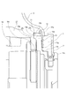
レンズマウント11とレンズ鏡筒14の位置決めと固定について説明する。レンズマウント11は、レンズ鏡筒14をスラスト方向(光軸方向)に位置決めするレンズ鏡筒当接面(取付面11d)を有している。レンズ鏡筒14には、レンズマウント11をスラスト方向に位置決めするレンズマウント当接面14aを有している。レンズ鏡筒当接面(取付面11d)をレンズマウント当接面14aに当接させた状態で、レンズマウント11を不図示のビスでレンズ鏡筒14に固定することで、レンズマウント11とレンズ鏡筒14の位置決めと固定を行うことができる。
Positioning and fixing of the
この結果、環状弾性部材12の光軸方向の位置は、環状弾性部材12の把持部12bが光軸方向において、外装環13の環状弾性部材側当接面13aとレンズマウント11の取付面11dとで圧縮して挟まれることにより決まる。一方、環状弾性部材12の径方向の位置は、外装環13の内周面13bとレンズマウント11の側周面11eとで挟まれることにより決まる。より詳細には、環状弾性部材12が光軸方向において環状弾性部材側当接面13aとレンズマウント11の取付面11dとで圧縮して挟まれる結果、環状弾性部材12が径方向に広がる。そして、環状弾性部材12が径方向において内周面13bと側周面11eとで挟まれることになる。
As a result, the positions of the annular elastic member 12 in the optical axis direction are such that the grip portion 12b of the annular elastic member 12 is in the optical axis direction with the annular elastic member side contact surface 13a of the outer ring 13 and the
図4及び図5に示すように、環状空隙部25の光軸直交方向の幅は環状弾性部材22の光軸直交方向の幅と同じである。そして、図4に示すように、交換レンズ20がカメラ本体100から取り外されている際には、環状空隙部25の底面に環状弾性部材22の一部(第1部分)22bが接触している。より詳細には、交換レンズ20がカメラ本体100から取り外されている際には、環状弾性部材22の当接面22cが、環状空隙部25の底面の一部である外装環23の弾性部材当接面23aに接触している。
As shown in FIGS. 4 and 5, the width of the
そして、図5に示すように、交換レンズ20がカメラ本体100に装着されている際には、環状空隙部25の底面に環状弾性部材22の一部(第1部分)22bに加えて、環状弾性部材22の一部(第2部分)22dも接触する。より詳細には、交換レンズ20がカメラ本体100に装着されている際には、当接面22cが当接面23aに当接する。そして、環状弾性部材22の当接面22dが、環状空隙部25の底面の一部である外装環23の弾性部材当接面23bに接触している。
Then, as shown in FIG. 5, when the interchangeable lens 20 is attached to the camera body 100, in addition to a part (first part) 22b of the annular
Claims (15)
前記アクセサリを前記カメラ本体に装着した際に前記第1マウント部と係合する第2マウント部と、
前記アクセサリを前記カメラ本体に装着した際に前記カメラ本体と接触することが可能な弾性部材と、
前記弾性部材を保持する筒部材と、を有し、
前記筒部材には、前記アクセサリを前記カメラ本体に装着した際に前記弾性部材の一部が入ることが可能な凹部が設けられている、
ことを特徴とするアクセサリ。 An accessory that can be attached to and detached from the camera body that has the first mount.
A second mounting portion that match engagement with the first mounting portion upon mounting the accessory on the camera body,
An elastic member that can come into contact with the camera body when the accessory is attached to the camera body.
It has a tubular member that holds the elastic member, and
The tubular member is provided with a recess into which a part of the elastic member can be inserted when the accessory is attached to the camera body.
An accessory that features that.
ことを特徴とする請求項1に記載のアクセサリ。 The recess is an annular recess, and the inner diameter of the annular recess is larger than the outer diameter of the second mount portion.
The accessory according to claim 1.
ことを特徴とする請求項1または2に記載のアクセサリ。 The recess is an annular recess, and the outer diameter of the annular recess is smaller than the outer diameter of the elastic member.
The accessory according to claim 1 or 2.
ことを特徴とする請求項1乃至3のいずれか一項に記載のアクセサリ。 The surface of the second mount portion on the tubular member side is cut or polished.
The accessory according to any one of claims 1 to 3, wherein the accessory.
ことを特徴とする請求項1乃至4のいずれか一項に記載のアクセサリ。 The elastic member is separated from the bottom surface of the recess when the accessory is removed from the camera body.
The accessory according to any one of claims 1 to 4, wherein the accessory.
ことを特徴とする請求項1乃至5のいずれか一項に記載のアクセサリ。 When the accessory is attached to the camera body, the elastic member comes into contact with the bottom surface of the recess.
The accessory according to any one of claims 1 to 5, wherein the accessory.
ことを特徴とする請求項1乃至4のいずれか一項に記載のアクセサリ。 When the accessory is removed from the camera body, the first portion of the elastic member is in contact with the bottom surface of the recess.
The accessory according to any one of claims 1 to 4, wherein the accessory.
前記アクセサリを前記カメラ本体に装着した際に前記凹部の底面に前記第1部分及び前記第2部分が接触する、
ことを特徴とする請求項7に記載のアクセサリ。 When the accessory is removed from the camera body, the second portion of the elastic member is separated from the bottom surface of the recess.
When the accessory is attached to the camera body, the first portion and the second portion come into contact with the bottom surface of the recess.
The accessory according to claim 7.
ことを特徴とする請求項1乃至8のいずれか一項に記載のアクセサリ。 When the accessory is attached to the camera body, the elastic member comes into contact with a metal member provided on the camera body.
The accessory according to any one of claims 1 to 8.
ことを特徴とする請求項1乃至9のいずれか一項に記載のアクセサリ。 The recess has a penetrating portion that penetrates inside or outside the tubular member.
The accessory according to any one of claims 1 to 9, wherein the accessory.
ことを特徴とする請求項1乃至11のいずれか一項に記載のアクセサリ。 The accessory is a lens device having a plurality of lenses.
The accessory according to any one of claims 1 to 11.
ことを特徴とする請求項1乃至11のいずれか一項に記載のアクセサリ。 The accessory is an adapter that can be attached between a lens device having a plurality of lenses and the camera body.
The accessory according to any one of claims 1 to 11.
請求項12に記載のアクセサリと、を備える、
ことを特徴とする撮像装置。 With the camera body
The accessory according to claim 12 is provided.
An imaging device characterized by this.
前記レンズ装置と、
請求項13に記載のアクセサリと、を備える、
ことを特徴とする撮像装置。 With the camera body
With the lens device
The accessory according to claim 13 is provided.
An imaging device characterized by this.
Priority Applications (3)
| Application Number | Priority Date | Filing Date | Title |
|---|---|---|---|
| JP2018151367A JP7224807B2 (en) | 2018-08-10 | 2018-08-10 | Accessory and imaging device equipped with the same |
| US16/528,399 US11327388B2 (en) | 2018-08-10 | 2019-07-31 | Accessory and imaging apparatus including the same |
| CN201910719215.1A CN110824815B (en) | 2018-08-10 | 2019-08-06 | Accessory and image forming apparatus including the same |
Applications Claiming Priority (1)
| Application Number | Priority Date | Filing Date | Title |
|---|---|---|---|
| JP2018151367A JP7224807B2 (en) | 2018-08-10 | 2018-08-10 | Accessory and imaging device equipped with the same |
Publications (3)
| Publication Number | Publication Date |
|---|---|
| JP2020027162A JP2020027162A (en) | 2020-02-20 |
| JP2020027162A5 true JP2020027162A5 (en) | 2021-09-09 |
| JP7224807B2 JP7224807B2 (en) | 2023-02-20 |
Family
ID=69407009
Family Applications (1)
| Application Number | Title | Priority Date | Filing Date |
|---|---|---|---|
| JP2018151367A Active JP7224807B2 (en) | 2018-08-10 | 2018-08-10 | Accessory and imaging device equipped with the same |
Country Status (3)
| Country | Link |
|---|---|
| US (1) | US11327388B2 (en) |
| JP (1) | JP7224807B2 (en) |
| CN (1) | CN110824815B (en) |
Family Cites Families (27)
| Publication number | Priority date | Publication date | Assignee | Title |
|---|---|---|---|---|
| JPS4636740B1 (en) * | 1968-04-06 | 1971-10-28 | ||
| JPS5937782Y2 (en) * | 1978-02-16 | 1984-10-19 | 富士写真フイルム株式会社 | Sealed structure of waterproof camera |
| US4963902A (en) | 1988-01-19 | 1990-10-16 | Canon Kabushiki Kaisha | Camera system |
| JP2864384B2 (en) | 1989-07-10 | 1999-03-03 | 株式会社ニコン | Mounting mechanism for camera and its interchangeable lens |
| JPH0453232U (en) * | 1990-09-10 | 1992-05-07 | ||
| JPH07128718A (en) | 1993-10-29 | 1995-05-19 | Olympus Optical Co Ltd | Mount mechanism for camera |
| US5946501A (en) | 1994-05-24 | 1999-08-31 | Asahi Kogaku Kogyo Kabushiki Kaisha | Waterproof and/or water-resistant camera |
| US5713048A (en) | 1994-05-24 | 1998-01-27 | Asahi Kogaku Kogyo Kabushiki Kaisha | Waterproof and/or water-resistant camera |
| JP3411670B2 (en) | 1994-05-24 | 2003-06-03 | ペンタックス株式会社 | Waterproof structure of drip-proof camera and open / close lid |
| JPH08106121A (en) | 1994-10-06 | 1996-04-23 | Asahi Optical Co Ltd | Waterproof structure |
| US5734935A (en) * | 1995-10-13 | 1998-03-31 | Nikon Corporation | Camera system and intermediate adapter |
| CN1244014C (en) | 1995-10-13 | 2006-03-01 | 株式会社尼康 | Camera system and intermediate adapter |
| JPH10186486A (en) | 1996-12-25 | 1998-07-14 | Canon Inc | Camera |
| JP3728080B2 (en) | 1997-12-17 | 2005-12-21 | キヤノン株式会社 | Cameras, camera accessories and camera systems |
| JP3835500B2 (en) * | 1998-03-16 | 2006-10-18 | 富士写真フイルム株式会社 | Waterproof structure of the camera |
| JP2001042407A (en) | 1999-07-28 | 2001-02-16 | Olympus Optical Co Ltd | Sealing device for camera |
| JP4636740B2 (en) | 2001-07-02 | 2011-02-23 | キヤノン株式会社 | Interchangeable lens and camera system having the same |
| JP2004101725A (en) * | 2002-09-06 | 2004-04-02 | Canon Inc | Lens arrangement and photographic device |
| JP3513512B1 (en) | 2003-08-01 | 2004-03-31 | キヤノン株式会社 | Interchangeable lens, interchangeable lens system and camera system |
| JP2009300928A (en) | 2008-06-17 | 2009-12-24 | Sigma Corp | Camera accessory and camera system |
| JP2009300926A (en) * | 2008-06-17 | 2009-12-24 | Sigma Corp | Camera accessory and camera system |
| JP5445479B2 (en) | 2011-01-28 | 2014-03-19 | 株式会社ニコン | Camera accessories, accessory side mount, camera body and body side mount |
| JP2013080078A (en) | 2011-10-04 | 2013-05-02 | Canon Inc | Lens barrel |
| JP6284410B2 (en) | 2014-04-11 | 2018-02-28 | 東洋ゴム工業株式会社 | Stabilizer bush |
| CN204178095U (en) | 2014-10-27 | 2015-02-25 | 深圳市大疆创新科技有限公司 | The fuselage of camera lens limit assembly, camera and camera model |
| JP2016224219A (en) | 2015-05-29 | 2016-12-28 | 東芝テリー株式会社 | Camera dust-proof construction |
| JP6838928B2 (en) | 2016-10-18 | 2021-03-03 | キヤノン株式会社 | Imaging device and mount adapter |
-
2018
- 2018-08-10 JP JP2018151367A patent/JP7224807B2/en active Active
-
2019
- 2019-07-31 US US16/528,399 patent/US11327388B2/en active Active
- 2019-08-06 CN CN201910719215.1A patent/CN110824815B/en active Active
Similar Documents
| Publication | Publication Date | Title |
|---|---|---|
| TWI507755B (en) | Lens barrel mechanical interference prevention measures for camera module voice coil motor design | |
| ATE509227T1 (en) | TRIPOD HEAD | |
| US9804481B2 (en) | Lens accessory, lens apparatus, and image pickup apparatus | |
| JP2016122043A (en) | Filter adapter and imaging device | |
| JP2020027162A5 (en) | ||
| JP2019010755A5 (en) | ||
| USD878551S1 (en) | Injection device | |
| TW201444650A (en) | Sleeve joint structure | |
| JP2016031482A5 (en) | ||
| US9910244B2 (en) | Housing for optical components | |
| JP7224807B2 (en) | Accessory and imaging device equipped with the same | |
| TWI406026B (en) | Ocular focus device | |
| JP5954986B2 (en) | Optical device | |
| JP6697330B2 (en) | Objective lens mount, objective lens unit, and optical measuring machine | |
| US9077878B2 (en) | Alternative lens insertion methods and associated features for camera modules | |
| JP2008051923A5 (en) | ||
| JP4606123B2 (en) | Eyecup / telescope adapter and eyepiece and telescope equipped with the same | |
| JP6906775B2 (en) | Shooting aid | |
| JP5155415B2 (en) | Endoscope accessories | |
| JP2014191243A (en) | Lens unit | |
| JP5529243B2 (en) | Fastener | |
| JP2019190578A (en) | Screw drop-off prevention mechanism | |
| JP2018032040A5 (en) | ||
| TWM534718U (en) | Accessory device mounted on bicycle handlebar | |
| US9995903B2 (en) | Lens device |