JP2020018655A - Deodorizing hanger - Google Patents

Deodorizing hanger Download PDF

Info

Publication number
JP2020018655A
JP2020018655A JP2018145500A JP2018145500A JP2020018655A JP 2020018655 A JP2020018655 A JP 2020018655A JP 2018145500 A JP2018145500 A JP 2018145500A JP 2018145500 A JP2018145500 A JP 2018145500A JP 2020018655 A JP2020018655 A JP 2020018655A
Authority
JP
Japan
Prior art keywords
hanger
deodorizing
holding member
support portion
ventilation
Prior art date
Legal status (The legal status is an assumption and is not a legal conclusion. Google has not performed a legal analysis and makes no representation as to the accuracy of the status listed.)
Pending
Application number
JP2018145500A
Other languages
Japanese (ja)
Inventor
康二 難波
Koji Namba
康二 難波
祐一 中垣
Yuichi Nakagaki
祐一 中垣
Current Assignee (The listed assignees may be inaccurate. Google has not performed a legal analysis and makes no representation or warranty as to the accuracy of the list.)
Panasonic Intellectual Property Management Co Ltd
Original Assignee
Panasonic Intellectual Property Management Co Ltd
Priority date (The priority date is an assumption and is not a legal conclusion. Google has not performed a legal analysis and makes no representation as to the accuracy of the date listed.)
Filing date
Publication date
Application filed by Panasonic Intellectual Property Management Co Ltd filed Critical Panasonic Intellectual Property Management Co Ltd
Priority to JP2018145500A priority Critical patent/JP2020018655A/en
Priority to CN201910646666.7A priority patent/CN110786707A/en
Publication of JP2020018655A publication Critical patent/JP2020018655A/en
Pending legal-status Critical Current

Links

Images

Abstract

To provide a deodorizing hanger on which trousers, a skirt or the like is hung to efficiently deodorize it.SOLUTION: A deodorizing hanger includes: a hanger part on which a jacket can be hung; and a deodorizing device which is installed in the hanger part to generate deodorization components from air. The hanger part includes a ventilation part configured to allow the air to pass through from one of the outside and the inside of the hanger part to the other. The ventilation part is provided at least on the bottom surface of the hanger part. A garment holding member 300 is disposed below the ventilation part. A left support part 302 and a right support part 301 are provided respectively on both right and left sides of the hanger part. The left support part 302 and the right support part 301 are each provided with a rock device for detachably supporting the garment holding member 300.SELECTED DRAWING: Figure 8

Description

本発明は、衣類を脱臭する機能を備えた脱臭ハンガーに関する。   The present invention relates to a deodorizing hanger having a function of deodorizing clothing.

オゾンなどの脱臭成分を放出することにより衣類を脱臭する機能を備えた脱臭ハンガーが知られている(例えば、特許文献1参照)。   2. Description of the Related Art A deodorizing hanger having a function of deodorizing clothing by releasing a deodorizing component such as ozone is known (for example, see Patent Document 1).

特許文献1に記載の脱臭ハンガーは、衣類がかけられるハンガー部、および、ハンガー部の内部に設けられたオゾン発生器を備える。オゾン発生器により生成されたオゾンは、ハンガー部の底部に設けられたスリットからハンガー部の外部に放出される。   The deodorant hanger described in Patent Literature 1 includes a hanger portion on which clothes are hung, and an ozone generator provided inside the hanger portion. Ozone generated by the ozone generator is discharged to the outside of the hanger from a slit provided at the bottom of the hanger.

特表2003−509144号公報JP-T-2003-509144

しかしながら、特許文献1に記載の脱臭ハンガーでは、ズボンやスカート等を掛けて効率的に脱臭することができない。   However, with the deodorizing hanger described in Patent Literature 1, it is not possible to efficiently deodorize by putting on pants, a skirt, or the like.

本発明は、上着をかけることが可能なハンガー部と、前記ハンガー部内に設けられ、空気から脱臭成分を生成する脱臭装置と、を備え、前記ハンガー部は、前記ハンガー部の外部および内部の一方から他方に空気が通過できるように構成される通気部を含み、前記通気部は、少なくとも前記ハンガー部の底面に設けられ、前記通気部の下方には、衣類保持部材が配置され、前記ハンガー部の左右両側には、左支持部と右支持部が設けられ、前記左支持部と前記右支持部には、それぞれ前記衣類保持部材を着脱自在に支持するためのロック装置が設けられている、脱臭ハンガーである。   The present invention includes a hanger portion to which a coat can be applied, and a deodorizing device provided in the hanger portion and generating a deodorizing component from air, wherein the hanger portion is provided outside and inside the hanger portion. A ventilation portion configured to allow air to pass from one side to the other, wherein the ventilation portion is provided at least on a bottom surface of the hanger portion, and a clothing holding member is disposed below the ventilation portion; A left support portion and a right support portion are provided on both left and right sides of the portion, and a lock device for detachably supporting the clothing holding member is provided on each of the left support portion and the right support portion. , Is a deodorant hanger.

これにより、使用者は、容易にズボンやスカート等を衣類保持部材に掛けることが可能であり、衣類保持部材に掛けた衣類全体に脱臭成分を含んだ空気をかけることが可能である。   Thereby, the user can easily hang the pants, the skirt, and the like on the clothing holding member, and can blow the air including the deodorizing component on the entire clothing hung on the clothing holding member.

図1は、実施の形態1の脱臭ハンガーに衣類が掛けられた状態の斜視図である。FIG. 1 is a perspective view of a state in which clothing is hung on the deodorizing hanger of the first embodiment. 図2は、実施の形態1の脱臭ハンガーの上部コンポーネントを取り外した状態を示す斜視図である。FIG. 2 is a perspective view showing a state where an upper component of the deodorizing hanger of the first embodiment is removed. 図3は、同実施の形態の脱臭ハンガーの背面図である。FIG. 3 is a rear view of the deodorizing hanger of the embodiment. 図4は、同実施の形態の脱臭ハンガーの底面図である。FIG. 4 is a bottom view of the deodorizing hanger of the embodiment. 図5は、図1の5−5線の断面を示す図である。FIG. 5 is a diagram showing a cross section taken along line 5-5 in FIG. 図6は、図1の6−6線の断面を示す図である。FIG. 6 is a diagram showing a cross section taken along line 6-6 in FIG. 図7は、実施の形態2の脱臭ハンガーの断面を示す図である。FIG. 7 is a diagram showing a cross section of the deodorizing hanger of the second embodiment. 図8は、実施の形態3の脱臭ハンガーの正面図である。FIG. 8 is a front view of the deodorizing hanger of the third embodiment. 図9は、実施の形態3の脱臭ハンガーの正面図である。FIG. 9 is a front view of the deodorizing hanger of the third embodiment. 図10は、図8に示す脱臭ハンガーの底面図である。FIG. 10 is a bottom view of the deodorizing hanger shown in FIG. 図11は、衣類保持部材を示す図である。FIG. 11 is a diagram illustrating a clothing holding member. 図12は、右支持部近傍を拡大した図である。FIG. 12 is an enlarged view of the vicinity of the right support portion. 図13は、右支持部近傍を拡大した図である。FIG. 13 is an enlarged view of the vicinity of the right support portion. 図14は、右支持部近傍を拡大し下方から見た斜視図である。FIG. 14 is an enlarged perspective view of the vicinity of the right support portion viewed from below. 図15は、脱臭ハンガーにズボンを掛けた状態の斜視図である。FIG. 15 is a perspective view showing a state in which pants are hung on the deodorizing hanger. 図16は、脱臭ハンガーにズボンを掛けた状態の右側面図である。FIG. 16 is a right side view of a state in which pants are hung on the deodorizing hanger.

以下、本発明の実施の形態について、図面を参照しながら説明する。なお、以下の説明では、同一または相当部分には同一符号を付し、重複する説明は省略する。また、本実施の形態によって、本発明が限定されるものではない。   Hereinafter, embodiments of the present invention will be described with reference to the drawings. In the following description, the same or corresponding parts will be denoted by the same reference characters, without redundant description. Further, the present invention is not limited by the present embodiment.

第1の実施態様は、上着をかけることが可能なハンガー部と、ハンガー部内に設けられ、空気から脱臭成分を生成する脱臭装置と、を備え、ハンガー部は、ハンガー部の外部および内部の一方から他方に空気が通過できるように構成される通気部を含み、通気部は、少なくともハンガー部の底面に設けられ、通気部の下方には、衣類保持部材が配置され、ハンガー部の左右両側には、左支持部と右支持部が設けられ、左支持部と右支持部には、それぞれ衣類保持部材を着脱自在に支持するためのロック装置が設けられている、脱臭ハンガーである。   The first embodiment includes a hanger portion to which an outerwear can be put, and a deodorizing device provided in the hanger portion and generating a deodorizing component from air, wherein the hanger portion is provided outside and inside the hanger portion. A ventilation portion configured to allow air to pass from one side to the other; the ventilation portion is provided at least on a bottom surface of the hanger portion; a clothing holding member is disposed below the ventilation portion; Is a deodorizing hanger provided with a left support portion and a right support portion, and each of the left support portion and the right support portion is provided with a lock device for detachably supporting the clothes holding member.

これにより、使用者は、容易にズボンやスカート等を衣類保持部材に掛けることが可能であり、衣類保持部材に掛けた衣類全体に脱臭成分を含んだ空気をかけることが可能である。   Thereby, the user can easily hang the pants, the skirt, and the like on the clothing holding member, and can blow the air including the deodorizing component on the entire clothing hung on the clothing holding member.

第2の実施態様は、右支持部と左支持部は、2つの内壁を有し、衣類保持部材が右支持部又は左支持部により支持された状態で、衣類保持部材の一部は2つの内壁間に位置し、2つの内壁の内、脱臭ハンガーの外側に位置する内壁により、衣類保持部材の回転角度が規制される脱臭ハンガーである。   In the second embodiment, the right support portion and the left support portion have two inner walls, and the garment holding member is supported by the right support portion or the left support portion. This is a deodorizing hanger in which the rotation angle of the clothes holding member is regulated by an inner wall located between the inner walls and located outside the deodorizing hanger among the two inner walls.

これにより、脱臭ハンガーを窓の近くに置いた場合でも、衣類保持部材を回転させた際に衣類保持部材が窓に当たることを回避することができる。   Thereby, even when the deodorizing hanger is placed near the window, it is possible to prevent the clothing holding member from hitting the window when the clothing holding member is rotated.

第3の実施態様は、右支持部と左支持部は、2つの内壁を有し、衣類保持部材が右支持部又は左支持部により支持された状態で、衣類保持部材の一部は2つの内壁間に位置し、2つの内壁の内、脱臭ハンガーの内側に位置する内壁には、衣類保持部材の一部が下方に落下することを防止するための突出部が配置され、ロック装置の一部が突出部である脱臭ハンガーである。   In the third embodiment, the right support portion and the left support portion have two inner walls, and the garment holding member is supported by the right support portion or the left support portion. A protruding portion for preventing a part of the clothes holding member from falling down is disposed on an inner wall located between the inner walls and located inside the deodorizing hanger among the two inner walls, and one of the locking devices is provided. This is a deodorizing hanger whose part is a protruding part.

これにより、使用者は、容易にズボンやスカート等を衣類保持部材に掛けることが可能であり、衣類保持部材に掛けた衣類全体に脱臭成分を含んだ空気をかけることが可能である。   Thereby, the user can easily hang the pants, the skirt, and the like on the clothing holding member, and can blow the air including the deodorizing component on the entire clothing hung on the clothing holding member.

第4の実施態様は、右支持部と左支持部は、脱臭ハンガーの内側に傾斜部を有する脱臭ハンガーである。   In the fourth embodiment, the right support portion and the left support portion are deodorizing hangers having inclined portions inside the deodorizing hanger.

これにより、衣類保持部材に掛けた衣類全体に脱臭成分を含んだ空気をかけることが可能である。   Thereby, it is possible to blow air containing a deodorizing component on the entire garment hung on the garment holding member.

第5の実施態様は、右支持部と左支持部は、脱臭ハンガーの外側に位置する側面を有し、側面には、衣類保持手段の支持状態から非支持状態へと変えるためのリリースボタンが配されている、脱臭ハンガーである。   In the fifth embodiment, the right support portion and the left support portion have side surfaces located outside the deodorizing hanger, and the side surface has a release button for changing the clothes holding unit from the support state to the non-support state. It is a deodorant hanger arranged.

これにより、使用者は、容易に衣類保持部材からズボンやスカート等を外すことが可能である。   Thus, the user can easily remove the pants, the skirt, and the like from the clothing holding member.

(実施の形態1)
以下、実施の形態1における脱臭ハンガーの構成について、図1から図6を参照しながら、説明する。
(Embodiment 1)
Hereinafter, the configuration of the deodorizing hanger in the first embodiment will be described with reference to FIGS. 1 to 6.

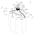
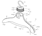
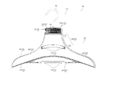
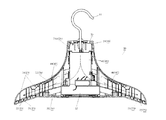
図1は、実施の形態1の脱臭ハンガー10に上着、シャツなどの衣類100が掛けられた状態を示す図である。図2は、同実施の形態の脱臭ハンガー10の上部コンポーネント30を取り外した状態を示す分解斜視図である。図3は、同実施の形態の脱臭ハンガー10の背面図である。図4は、同実施の形態の脱臭ハンガー10の底面図である。図5は、図1の5−5線の断面を示す図である。図6は、図1の6−6線の断面を示す図である。   FIG. 1 is a diagram showing a state in which clothing 100 such as a jacket and a shirt is hung on a deodorizing hanger 10 of the first embodiment. FIG. 2 is an exploded perspective view showing a state where the upper component 30 of the deodorizing hanger 10 of the embodiment is removed. FIG. 3 is a rear view of the deodorizing hanger 10 of the embodiment. FIG. 4 is a bottom view of the deodorizing hanger 10 of the embodiment. FIG. 5 is a diagram showing a cross section taken along line 5-5 in FIG. FIG. 6 is a diagram showing a cross section taken along line 6-6 in FIG.

図1に示すように、本実施の形態の脱臭ハンガー10は、フック部11およびハンガー部20などを含む。フック部11は、脱臭ハンガー10を、洋服タンスやクローゼットに設けられるパイプPなどに吊るす際に利用される。フック部11は、衣類100および脱臭ハンガー10を支持するために十分な強度を有する材料で形成される。材料の第1例は、例えばステンレスなどの金属である。材料の第2例は、例えばポリプロピレンなどの樹脂である。   As shown in FIG. 1, the deodorizing hanger 10 of the present embodiment includes a hook portion 11, a hanger portion 20, and the like. The hook part 11 is used when the deodorizing hanger 10 is hung on a clothes P or a pipe P provided in a closet. The hook portion 11 is formed of a material having sufficient strength to support the clothes 100 and the deodorizing hanger 10. A first example of a material is a metal such as, for example, stainless steel. A second example of the material is a resin such as, for example, polypropylene.

ハンガー部20は、ネック部50と、アーム部60などを含む。ネック部50は、衣類100の襟101を支持できるように構成される。アーム部60は、衣類100の肩102を支持できるように構成される。   The hanger part 20 includes a neck part 50, an arm part 60, and the like. The neck portion 50 is configured to support the collar 101 of the garment 100. The arm section 60 is configured to support the shoulder 102 of the garment 100.

ネック部50は、上部51および下部52などを含む。ネック部50の下部52は、衣類100の襟101と近接する部分に相当する。具体的には、ネック部50の下部52は、図3に示すように、例えばハンガー部20の底部22からハンガー部20の上部21までの長さの20%〜50%だけハンガー部20の底部22から離れた部分までの範囲内に設けられる。   The neck portion 50 includes an upper portion 51, a lower portion 52, and the like. The lower portion 52 of the neck portion 50 corresponds to a portion of the garment 100 that is close to the collar 101. Specifically, as shown in FIG. 3, the lower part 52 of the neck part 50 is, for example, 20% to 50% of the length from the bottom part 22 of the hanger part 20 to the upper part 21 of the hanger part 20, and It is provided in a range up to a portion away from 22.

ネック部50の上部51は、ネック部50の下部52よりも上方の部分に相当し、上部コンポーネント30を含む。そのため、ネック部50の上部51は、脱臭ハンガー10に衣類100が掛けられた状態において、衣類100から露出する。   The upper portion 51 of the neck portion 50 corresponds to a portion above the lower portion 52 of the neck portion 50 and includes the upper component 30. Therefore, the upper part 51 of the neck part 50 is exposed from the clothing 100 when the clothing 100 is hung on the deodorizing hanger 10.

また、ハンガー部20は、上部コンポーネント30の側面に、端子部25を備える。端子部25は、外部電源(図示せず)と電源ケーブルCにより接続可能に構成される。端子部25は、外部電源から供給される電力を、ハンガー部20の内部に設けられる電子機器に供給する。電子機器は、例えば、脱臭成分を生成する脱臭装置26(図5参照)、および、表示部23(図2参照)などである。端子部25は、脱臭ハンガー10に衣類100が掛けられた状態において、衣類100で覆われない位置に設けられる。そのため、使用者は、掛けられた衣類100を動かすことなく、電源ケーブルCを端子部25に接続できる。   Further, the hanger section 20 includes a terminal section 25 on a side surface of the upper component 30. The terminal section 25 is configured to be connectable to an external power supply (not shown) by a power cable C. The terminal unit 25 supplies electric power supplied from an external power supply to an electronic device provided inside the hanger unit 20. The electronic devices include, for example, a deodorizing device 26 (see FIG. 5) that generates a deodorizing component, and a display unit 23 (see FIG. 2). The terminal portion 25 is provided at a position where the clothing 100 is not covered with the clothing 100 when the clothing 100 is hung on the deodorizing hanger 10. Therefore, the user can connect the power cable C to the terminal unit 25 without moving the hanged clothing 100.

さらに、ハンガー部20は、通気部70を含む。通気部70は、ハンガー部20の外部および内部の一方から他方に空気が通過できるように配設される。通気部70は、第1通
気部71と、第2通気部72などを、さらに含む。第1通気部71は、ハンガー部20の上方側の部分に相当する、ネック部50の上部51に設けられる。第2通気部72は、ハンガー部20の下方側の部分に相当する、アーム部60の下部52およびネック部50の、少なくとも一方に設けられる。第2通気部72は、後述する脱臭装置26で生成される脱臭成分を含む空気が、ハンガー部20の内部から外部に流れるように配設される。
Further, the hanger section 20 includes a ventilation section 70. The ventilation part 70 is provided so that air can pass from one of the outside and the inside of the hanger part 20 to the other. The ventilation section 70 further includes a first ventilation section 71, a second ventilation section 72, and the like. The first ventilation part 71 is provided in the upper part 51 of the neck part 50 corresponding to the upper part of the hanger part 20. The second ventilation part 72 is provided on at least one of the lower part 52 of the arm part 60 and the neck part 50 corresponding to the lower part of the hanger part 20. The second ventilation section 72 is provided so that air containing a deodorizing component generated by the deodorizing device 26 described later flows from the inside of the hanger section 20 to the outside.

ハンガー部20は、図1に示すように、上記上部コンポーネント30、およびハンガー部本体40などで構成される。ハンガー部本体40は、ネック部50の上部51の一部と下部52、およびアーム部60などを含む。ハンガー部本体40は、ハンガー部20の外郭を構成し、内部は中空である。ハンガー部本体40は、衣類100(図1参照)を掛けるために適した材料で形成される。材料の第1例は、例えばポリプロピレンなどの樹脂である。材料の第2例は、例えばアルミニウムなどの金属である。ハンガー部本体40は、流通路42に連通する開口部41を含む。流通路42は、開口部41からハンガー部本体40の内部に向かって形成される。流通路42は、空気が流れる流路を構成する。   As shown in FIG. 1, the hanger section 20 includes the upper component 30 and a hanger section main body 40. The hanger part main body 40 includes a part of the upper part 51 of the neck part 50, a lower part 52, an arm part 60 and the like. The hanger part main body 40 forms an outer shell of the hanger part 20, and the inside is hollow. The hanger body 40 is formed of a material suitable for hanging the garment 100 (see FIG. 1). A first example of the material is a resin such as, for example, polypropylene. A second example of a material is a metal such as, for example, aluminum. The hanger body 40 includes an opening 41 communicating with the flow passage 42. The flow passage 42 is formed from the opening 41 toward the inside of the hanger main body 40. The flow path 42 forms a flow path through which air flows.

上部コンポーネント30は、フック部11の基端12と接続され、ハンガー部本体40とは別体の部品で構成される。上部コンポーネント30は、例えば略楕円柱状(楕円柱状を含む)の形状で、例えばポリプロピレンなどの樹脂で形成される。上部コンポーネント30は、ハンガー部本体40の開口部41を覆うように着脱可能に取り付けられる。上部コンポーネント30は、上下方向に離間して設けられ、周方向に沿って延びる複数のフランジ31を含む。   The upper component 30 is connected to the base end 12 of the hook portion 11 and is configured as a component separate from the hanger portion main body 40. The upper component 30 has, for example, a substantially elliptical column shape (including an elliptical column shape), and is formed of a resin such as polypropylene. The upper component 30 is detachably attached so as to cover the opening 41 of the hanger unit main body 40. The upper component 30 includes a plurality of flanges 31 that are vertically spaced apart and extend along the circumferential direction.

表示部23(図2参照)および操作部24は、図1に示すように、ハンガー部本体40のネック部50の上部51側に設けられる。表示部23は、例えば発光ダイオード(LED)で構成され、脱臭ハンガー10の動作状況を表示する。表示部23は、ハンガー部本体40に上部コンポーネント30が取り付けられた状態において、上部コンポーネント30に覆われ、内包される。このとき、使用者は、上部コンポーネント30に形成された複数のフランジ31の間から、表示部23の発光を視認できる。これにより、使用者は、脱臭ハンガー10の動作状況を、把握できる。   The display unit 23 (see FIG. 2) and the operation unit 24 are provided on the upper portion 51 side of the neck portion 50 of the hanger unit main body 40, as shown in FIG. The display unit 23 includes, for example, a light emitting diode (LED), and displays an operation state of the deodorizing hanger 10. The display unit 23 is covered and included by the upper component 30 in a state where the upper component 30 is attached to the hanger unit main body 40. At this time, the user can visually recognize the light emission of the display unit 23 from between the plurality of flanges 31 formed on the upper component 30. Thereby, the user can grasp the operation state of the deodorizing hanger 10.

操作部24は、例えば、ボタン24Aを含む。使用者のボタン24Aの操作により、脱臭ハンガー10に対する動作指示が入力される。具体的には、ボタン24Aが押下された場合、操作部24は、脱臭ハンガー10の脱臭装置26に脱臭動作を開始させるための信号を、生成する。ボタン24Aが、再度、押下された場合、操作部24は、脱臭ハンガー10の脱臭装置26に脱臭動作を停止させるための信号を、生成する。   The operation unit 24 includes, for example, a button 24A. By operating the button 24A by the user, an operation instruction for the deodorizing hanger 10 is input. Specifically, when the button 24A is pressed, the operation unit 24 generates a signal for causing the deodorizing device 26 of the deodorizing hanger 10 to start the deodorizing operation. When the button 24A is pressed again, the operation unit 24 generates a signal for causing the deodorizing device 26 of the deodorizing hanger 10 to stop the deodorizing operation.

表示部23および操作部24は、脱臭ハンガー10に衣類100が掛けられた状態において、衣類100に覆われない位置に配設される。これにより、表示部23の視認性および操作部24の操作性が、維持できる。   The display unit 23 and the operation unit 24 are provided at positions where the clothing 100 is not covered by the clothing 100 when the clothing 100 is hung on the deodorizing hanger 10. Thereby, the visibility of the display unit 23 and the operability of the operation unit 24 can be maintained.

上述したように、ハンガー部20の通気部70は、図2に示すように、第1通気部71および第2通気部72を含む。通気部70は、脱臭成分をハンガー部20の外部に放出、または、外部の空気を内部に取り入れ可能に配設される。通気部70の第2通気部72は、先端側通気部73と、中心側通気部76などを含む。先端側通気部73は、アーム部60の先端部62側に設けられる。中心側通気部76は、先端側通気部73よりもアーム部60の中心63側に設けられる。   As described above, the ventilation section 70 of the hanger section 20 includes the first ventilation section 71 and the second ventilation section 72 as shown in FIG. The ventilation part 70 is disposed so that a deodorizing component can be released to the outside of the hanger part 20 or external air can be taken into the inside. The second ventilation section 72 of the ventilation section 70 includes a distal-side ventilation section 73, a center-side ventilation section 76, and the like. The distal-side ventilation portion 73 is provided on the distal end portion 62 side of the arm portion 60. The center side ventilation section 76 is provided closer to the center 63 of the arm section 60 than the tip side ventilation section 73.

先端側通気部73は、上部先端側通気部74および下部先端側通気部75などを含む。上部先端側通気部74は、第1上部先端側通気部74Aおよび第2上部先端側通気部74Bなどを含む。中心側通気部76は、上部中心側通気部77および下部中心側通気部78
などを含む。
The distal-side ventilation section 73 includes an upper distal-side ventilation section 74, a lower distal-side ventilation section 75, and the like. The upper distal side ventilation section 74 includes a first upper distal side ventilation section 74A, a second upper distal side ventilation section 74B, and the like. The center side ventilation section 76 includes an upper center side ventilation section 77 and a lower center side ventilation section 78.
Including.

このとき、上部中心側通気部77は、上部中心側通気部77を通過する空気の流路面積が、上部先端側通気部74を通過する空気の流路面積よりも広くなるように構成される。具体的には、空気の流路面積は、上部中心側通気部77、第2上部先端側通気部74B、第1上部先端側通気部74Aの順に広くなるように構成される。さらに、上部中心側通気部77における空気の流路面積が、上部先端側通気部74における空気の流路面積よりも広くなるように形成される。そのため、上部中心側通気部77から外部に放出される脱臭成分の量が多くなる。これにより、臭いが付着しやすい衣類100の襟101側に、より多くの脱臭成分が供給される。その結果、衣類100の襟101に付着した臭いを、適切に脱臭できる。さらに、上部中心側通気部77は、ハンガー部20の上方側(フック部11側)に向けて開口するように形成される。そのため、衣類100の襟101に向けて、より確実に脱臭成分を放出できる。   At this time, the upper center side ventilation part 77 is configured such that the flow path area of the air passing through the upper center side ventilation part 77 is larger than the flow path area of the air passing through the upper tip side ventilation part 74. . Specifically, the flow path area of the air is configured to increase in the order of the upper center side ventilation portion 77, the second upper end side ventilation portion 74B, and the first upper end side ventilation portion 74A. Furthermore, the air passage area in the upper center side ventilation section 77 is formed to be larger than the air passage area in the upper front end side ventilation section 74. Therefore, the amount of the deodorizing component released from the upper center side ventilation portion 77 to the outside increases. As a result, more deodorizing components are supplied to the side of the collar 101 of the garment 100 to which the odor tends to adhere. As a result, the odor attached to the collar 101 of the garment 100 can be appropriately deodorized. Further, the upper center side ventilation portion 77 is formed so as to open toward the upper side of the hanger portion 20 (the hook portion 11 side). Therefore, the deodorizing component can be more reliably released toward the collar 101 of the garment 100.

また、通気部70の第1通気部71は、図3に示すように、上部コンポーネント30の複数のフランジ31間に形成される。第1通気部71は、ハンガー部本体40の開口部41と連通する。これにより、外部の空気を、第1通気部71を介して、ハンガー部本体40の流通路42(図2参照)に取り入れることができる。なお、第1通気部71は、例えば、孔、スリット、メッシュなどで形成される。図3に示す例では、第1通気部71は、整列した複数のスリット71Aで形成している。そのため、第1通気部71における、空気の流路面積を広く取ることができる。その結果、第1通気部71を通過する空気の流量を増やすことができる。   Further, the first ventilation portion 71 of the ventilation portion 70 is formed between the plurality of flanges 31 of the upper component 30 as shown in FIG. The first ventilation section 71 communicates with the opening 41 of the hanger section main body 40. Thus, external air can be introduced into the flow passage 42 (see FIG. 2) of the hanger unit main body 40 via the first ventilation part 71. The first ventilation section 71 is formed of, for example, a hole, a slit, a mesh, or the like. In the example shown in FIG. 3, the first ventilation section 71 is formed by a plurality of aligned slits 71A. Therefore, the flow area of the air in the first ventilation section 71 can be increased. As a result, the flow rate of the air passing through the first ventilation section 71 can be increased.

つまり、ハンガー部20は、上述したように、上部コンポーネント30とハンガー部本体40とを結合することにより構成される。これにより、上部コンポーネント30は、容易に交換することができる。そのため、上部コンポーネント30の交換により、第1通気部71における空気の流路の形状を容易に変更できる。その結果、必要性能に応じて、通過する空気の流量を任意に調整できる。   That is, the hanger portion 20 is configured by coupling the upper component 30 and the hanger portion main body 40 as described above. This allows the upper component 30 to be easily replaced. Therefore, the shape of the air flow path in the first ventilation portion 71 can be easily changed by replacing the upper component 30. As a result, the flow rate of the passing air can be arbitrarily adjusted according to the required performance.

さらに、第2通気部72は、ハンガー部20のハンガー部本体40の底部22側にも配設される。これにより、脱臭装置26により生成された脱臭成分を含む空気は、自重により、ハンガー部本体40の底部22の第2通気部72から、下方に流れる。そのため、ハンガー部20の外部から第1通気部71を通過して脱臭装置26に流れる空気と、脱臭装置26により生成された脱臭成分を含む空気の流れとの干渉が、抑制される。なお、第2通気部72は、例えば孔、スリット、メッシュなどで形成される。   Further, the second ventilation part 72 is also provided on the hanger part main body 40 side of the hanger part 20 on the bottom part 22 side. Thus, the air containing the deodorizing component generated by the deodorizing device 26 flows downward from the second ventilation portion 72 of the bottom portion 22 of the hanger portion main body 40 by its own weight. Therefore, interference between the air flowing from the outside of the hanger section 20 through the first ventilation section 71 to the deodorizing device 26 and the flow of the air containing the deodorizing component generated by the deodorizing device 26 is suppressed. The second ventilation section 72 is formed of, for example, a hole, a slit, a mesh, or the like.

また、アーム部60の底部61には、図4に示すように、下部先端側通気部75および下部中心側通気部78が配設される。下部先端側通気部75は、アーム部60の先端部62側の底部61に形成される。   As shown in FIG. 4, a lower end side ventilation section 75 and a lower center side ventilation section 78 are provided on the bottom 61 of the arm section 60. The lower tip side ventilation part 75 is formed in the bottom part 61 on the tip part 62 side of the arm part 60.

一方、下部中心側通気部78は、アーム部60の先端部62より内側の底部61に形成される。   On the other hand, the lower center side ventilation portion 78 is formed in the bottom portion 61 inside the distal end portion 62 of the arm portion 60.

このとき、下部先端側通気部75は、下部先端側通気部75を通過する空気の流路面積が、下部中心側通気部78を通過する空気の流路面積よりも広くなるように構成される。つまり、下部先端側通気部75における空気の流路面積が、下部中心側通気部78における空気の流路面積よりも広くなるように形成される。そのため、下部先端側通気部75から外部に放出される脱臭成分の量が多くなる。これにより、下部先端側通気部75からハンガー部20の外部に放出された脱臭成分を含む空気の多くが、衣類100の袖103から流入し、袖口まで到達しやすくなる。その結果、脱臭成分により、衣類100の袖10
3から袖口にかけて、より効果的に脱臭できる。
At this time, the lower distal side ventilation section 75 is configured such that the flow area of the air passing through the lower distal side ventilation section 75 is larger than the flow area of the air passing through the lower central side ventilation section 78. . That is, the air passage area in the lower front side ventilation section 75 is formed to be larger than the air passage area in the lower center side ventilation section 78. Therefore, the amount of the deodorizing component released to the outside from the lower end side ventilation section 75 increases. Accordingly, much of the air containing the deodorizing component released from the lower end side ventilation section 75 to the outside of the hanger section 20 flows from the sleeve 103 of the garment 100 and easily reaches the cuff. As a result, the sleeve 10 of the garment 100
From 3 to cuffs, more effective deodorization.

また、脱臭ハンガー10は、図5に示すように、内部に、脱臭装置26および制御部27などを備える。脱臭装置26は、衣類100(図1参照)を脱臭する脱臭成分を生成する。脱臭成分は、例えば帯電微粒子水、オゾン、ラジカル、空気イオンなどが例示される。   As shown in FIG. 5, the deodorizing hanger 10 includes a deodorizing device 26 and a control unit 27 therein. The deodorizing device 26 generates a deodorizing component for deodorizing the clothing 100 (see FIG. 1). Examples of the deodorizing component include charged fine particle water, ozone, radicals, and air ions.

具体的には、脱臭成分が帯電微粒子水の場合、脱臭装置26は、放電電極(図示せず)から空気に対して放電し、脱臭成分を生成する。このとき、脱臭装置26は、ペルチェ素子(図示せず)を備える構成が好ましい。つまり、ペルチェ素子で空気を冷却し、空気中の水分を凝縮させる。そして、凝縮した水分を、放電により静電霧化する。これにより、例えば帯電微粒子水などの脱臭成分を、効率的に生成できる。   Specifically, when the deodorizing component is the charged fine particle water, the deodorizing device 26 discharges the air from the discharge electrode (not shown) to the air to generate the deodorizing component. At this time, it is preferable that the deodorizing device 26 includes a Peltier element (not shown). That is, the air is cooled by the Peltier element, and the moisture in the air is condensed. Then, the condensed water is electrostatically atomized by discharge. Thereby, for example, a deodorizing component such as charged fine particle water can be efficiently generated.

制御部27は、使用者による操作部24を介した動作指示に応じて、脱臭装置26の動作を制御する。つまり、制御部27は、操作部24のボタン24Aの押下操作により、脱臭ハンガー10に脱臭動作を開始させるための信号を受信すると、脱臭装置26を動作させるように制御する。また、制御部27は、操作部24のボタン24Aの再度の押下操作により、脱臭ハンガー10に脱臭動作を停止させるための信号を受信すると、脱臭装置26を停止させるように制御する。なお、制御部27は、例えばマイクロコンピュータなどで構成され、上記制御動作を実行する。   The control unit 27 controls the operation of the deodorizing device 26 in accordance with an operation instruction from the user via the operation unit 24. That is, when the control unit 27 receives a signal for starting the deodorizing operation of the deodorizing hanger 10 by pressing the button 24A of the operating unit 24, the control unit 27 controls the deodorizing device 26 to operate. Further, when the control unit 27 receives a signal for stopping the deodorizing operation by the deodorizing hanger 10 by pressing the button 24A of the operating unit 24 again, the control unit 27 controls the deodorizing device 26 to stop. The control unit 27 is configured by, for example, a microcomputer or the like, and performs the above-described control operation.

また、ハンガー部本体40は、図5に示すように、内部に、上述した流通路42を備える。流通路42は、通路部43および貯留部44などを含む。通路部43は、流通路42の脱臭装置26よりも上方側に設けられる部分に相当する。貯留部44は、流通路42の脱臭装置26よりも下方側に設けられる部分に相当する。   Further, as shown in FIG. 5, the hanger unit main body 40 includes the above-described flow passage 42 therein. The flow passage 42 includes a passage portion 43, a storage portion 44, and the like. The passage portion 43 corresponds to a portion provided above the deodorizing device 26 in the flow passage 42. The storage section 44 corresponds to a portion provided below the deodorizing device 26 in the flow passage 42.

貯留部44は、脱臭装置26により生成された脱臭成分を貯留可能に構成される。   The storage unit 44 is configured to be able to store the deodorizing component generated by the deodorizing device 26.

なお、図5の点線矢印は、ハンガー部20内の空気の流れを示している。つまり、外部の空気は、第1通気部71から、ハンガー部本体40の流通路42内に取り入れられる。取り入れられた空気は、流通路42の通路部43を通過して、脱臭装置26に到達する。到達した空気は、脱臭装置26により生成される脱臭成分と混合される。これにより、脱臭成分を含んだ空気が生成される。そして、生成された脱臭成分を含む空気は、貯留部44に貯められる。   Note that the dotted arrows in FIG. 5 indicate the flow of air in the hanger unit 20. That is, the outside air is taken into the flow passage 42 of the hanger main body 40 from the first ventilation part 71. The introduced air passes through the passage 43 of the flow passage 42 and reaches the deodorizing device 26. The arriving air is mixed with the deodorizing component generated by the deodorizing device 26. As a result, air containing a deodorizing component is generated. Then, the air containing the generated deodorizing component is stored in the storage unit 44.

なお、通気部70は、上述したように、第1通気部71と、第2通気部72などを含む。   The ventilation section 70 includes the first ventilation section 71 and the second ventilation section 72 as described above.

第1通気部71は、脱臭装置26よりもハンガー部20の上方側に部分に設けられる。具体的には、第1通気部71は、ネック部50の上部51の上部コンポーネント30に設けられる。これにより、ハンガー部20に衣類100が掛けられたときに、第1通気部71は、衣類100により覆われにくい。そのため、衣類100により、脱臭装置26に供給される空気の量が、減少しにくい。その結果、脱臭ハンガー10は、脱臭装置26で脱臭成分を含む空気を効率的に生成できる。   The first ventilation part 71 is provided in a part above the hanger part 20 with respect to the deodorizing device 26. Specifically, the first ventilation part 71 is provided in the upper component 30 of the upper part 51 of the neck part 50. Thus, when the clothes 100 are hung on the hanger section 20, the first ventilation section 71 is less likely to be covered by the clothes 100. Therefore, the amount of air supplied to the deodorizing device 26 by the clothing 100 is not easily reduced. As a result, the deodorizing hanger 10 can efficiently generate the air containing the deodorizing component in the deodorizing device 26.

一方、第2通気部72は、脱臭装置26よりもハンガー部20の下方側の部分に設けられる。具体的には、第2通気部72は、ハンガー部20のハンガー部本体40のネック部50の下部52およびアーム部60の、少なくとも一方に設けられる。そして、脱臭成分を含む空気は、第2通気部72を通過して、ハンガー部20の外部に、適量に放出される。   On the other hand, the second ventilation portion 72 is provided in a portion below the hanger portion 20 with respect to the deodorizing device 26. Specifically, the second ventilation part 72 is provided on at least one of the lower part 52 of the neck part 50 and the arm part 60 of the hanger part main body 40 of the hanger part 20. Then, the air containing the deodorizing component passes through the second ventilation section 72 and is discharged to the outside of the hanger section 20 in an appropriate amount.

このとき、図6に示すように、貯留部44に貯められた脱臭成分を含む空気は、第2通気部72から外部に放出される。   At this time, as shown in FIG. 6, the air containing the deodorizing component stored in the storage section 44 is discharged from the second ventilation section 72 to the outside.

そして、脱臭成分の一部は、貯留部44に滞留する。貯留部44に滞留する脱臭成分は、重力(自重)、または、ハンガー部20内に形成された空気の流れなどにより、ハンガー部20内を移動する。これにより、脱臭成分を含む空気が、通気部70からハンガー部20の外部に放出される。つまり、脱臭装置26による脱臭成分の生成量が低下しても、貯留部44に滞留している脱臭成分が、放出される。そのため、脱臭装置26による脱臭成分の生成量の低下が、貯留部44に滞留している脱臭成分により補償される。これにより、脱臭成分の低下による衣類100の脱臭機能の低下が、抑制される。その結果、例え脱臭装置26による脱臭成分の生成量が低下した場合でも、衣類100などに付着した臭いを、より効率よく脱臭できる。   Then, a part of the deodorizing component stays in the storage unit 44. The deodorizing component staying in the storage section 44 moves in the hanger section 20 due to gravity (own weight) or the flow of air formed in the hanger section 20. As a result, the air containing the deodorizing component is released from the ventilation section 70 to the outside of the hanger section 20. That is, even if the amount of the deodorizing component generated by the deodorizing device 26 decreases, the deodorizing component retained in the storage unit 44 is released. Therefore, the reduction in the amount of the deodorizing component generated by the deodorizing device 26 is compensated for by the deodorizing component remaining in the storage unit 44. Thereby, a decrease in the deodorizing function of the garment 100 due to a decrease in the deodorizing component is suppressed. As a result, even if the amount of the deodorizing component generated by the deodorizing device 26 is reduced, the odor attached to the clothes 100 and the like can be deodorized more efficiently.

なお、貯留部44は、脱臭装置26から第2通気部72までの、空気が流れる流路上に設けることが好ましい。これにより、脱臭装置26により生成される脱臭成分が、貯留部44に滞留しやすくなる。   The storage section 44 is preferably provided on a flow path from the deodorizing device 26 to the second ventilation section 72 through which air flows. This makes it easier for the deodorizing component generated by the deodorizing device 26 to stay in the storage unit 44.

また、脱臭装置26から第2通気部72までの距離が、第1通気部71から脱臭装置26までの距離よりも長くなるように構成することが好ましい。これにより、脱臭ハンガー10が貯留部44を備える構成の場合、貯留部44の容積を大きくできる。そのため、貯留部44に、より多くの脱臭成分を含んだ空気を貯留できる。その結果、脱臭装置26により生成される脱臭成分が増減しても、より均一な量の脱臭成分を含む空気を、衣類100などに、効率的に放出して脱臭できる。   Further, it is preferable that the distance from the deodorizing device 26 to the second ventilation portion 72 be longer than the distance from the first ventilation portion 71 to the deodorizing device 26. Thus, in the case where the deodorizing hanger 10 has the storage section 44, the capacity of the storage section 44 can be increased. Therefore, air containing more deodorizing components can be stored in the storage unit 44. As a result, even if the deodorizing component generated by the deodorizing device 26 increases or decreases, air containing a more uniform amount of the deodorizing component can be efficiently released to the clothing 100 and the like to be deodorized.

(実施の形態2)
以下、実施の形態2における脱臭ハンガーの構成について、図7を参照しながら、説明する。
(Embodiment 2)
Hereinafter, the configuration of the deodorizing hanger in the second embodiment will be described with reference to FIG.

図7に示すように、実施の形態2の脱臭ハンガー10は、吸込口28Aおよび吐出口28Bを備える電動ファン28を、さらに備える点で、実施の形態1と相違する。その他の構成要素や動作などは、実施の形態1の脱臭ハンガー10と実質的に同じであるため、説明を省略する場合がある。   As shown in FIG. 7, the deodorizing hanger 10 of the second embodiment is different from the first embodiment in further including an electric fan 28 having a suction port 28A and a discharge port 28B. Other components, operations, and the like are substantially the same as those of the deodorizing hanger 10 of the first embodiment, and thus description thereof may be omitted.

つまり、実施の形態2の脱臭ハンガー10は、図7に示すように、電動ファン28が、例えばハンガー部本体40のネック部50近傍の内部に配設される。   That is, in the deodorizing hanger 10 of the second embodiment, as shown in FIG. 7, the electric fan 28 is disposed inside, for example, the vicinity of the neck 50 of the hanger main body 40.

電動ファン28は、図7の破線矢印で示すように、脱臭装置26により生成された脱臭成分を含む空気を、先端側通気部73に含まれる下部先端側通気部75に、効率よく流すことができる。そのため、脱臭成分の、例えば衣類100の袖103(図1参照)などへの拡散量が多くなる。これにより、脱臭ハンガー10の脱臭機能を、さらに高めることができる。その結果、衣類100の袖103の、例えば袖口などに付着した臭いを、より強力に脱臭できる。   The electric fan 28 can efficiently flow the air containing the deodorizing component generated by the deodorizing device 26 to the lower distal side ventilation section 75 included in the distal side ventilation section 73 as shown by the broken line arrow in FIG. it can. Therefore, the diffusion amount of the deodorizing component to, for example, the sleeve 103 (see FIG. 1) of the garment 100 increases. Thereby, the deodorizing function of the deodorizing hanger 10 can be further enhanced. As a result, the odor attached to, for example, the cuffs of the sleeve 103 of the garment 100 can be more strongly deodorized.

このとき、脱臭装置26を、ハンガー部20の内部における電動ファン28の吐出口28B側に設けることが好ましい。この構成により、脱臭装置26により生成される脱臭成分の電動ファン28への付着を、より確実に防止できる。そのため、脱臭成分を、効率よく、ハンガー部20の外部に排出できる。   At this time, it is preferable to provide the deodorizing device 26 on the discharge port 28B side of the electric fan 28 inside the hanger section 20. With this configuration, it is possible to more reliably prevent the deodorizing component generated by the deodorizing device 26 from adhering to the electric fan 28. Therefore, the deodorizing component can be efficiently discharged to the outside of the hanger section 20.

また、電動ファン28の吸込口28Aは、ハンガー部本体40のネック部50の上部5
1内に配設される。つまり、第2通気部72よりも電動ファン28の吸込口28Aの近くに、第1通気部71が配設される。これにより、ハンガー部20の内部における、第1通気部71から電動ファン28の吸込口28Aまでの、空気が流れる流路が短くなる。その結果、電動ファン28により、上部コンポーネント30の第1通気部71から、効率的に、空気をハンガー部20内に吸引できる。
The suction port 28 </ b> A of the electric fan 28 is connected to the upper part 5 of the neck 50 of the hanger body 40.
1. That is, the first ventilation section 71 is provided closer to the suction port 28A of the electric fan 28 than the second ventilation section 72 is. Thereby, the flow path in which air flows from the first ventilation part 71 to the suction port 28A of the electric fan 28 inside the hanger part 20 is shortened. As a result, the electric fan 28 can efficiently suck air from the first ventilation portion 71 of the upper component 30 into the hanger portion 20.

一方、電動ファン28の吐出口28Bは、ネック部50の下部52内、またはアーム部60内に配設される。つまり、第1通気部71よりも電動ファン28の吐出口28Bの近くに、第2通気部72が配設される。そのため、脱臭装置26により生成された脱臭成分を含む空気の流れと、電動ファン28に吸引される空気の流れとの干渉が、生じにくい。これにより、ハンガー部20の外部に放出される脱臭成分の濃度などの変化を抑制して、より安定した脱臭性能を維持できる。   On the other hand, the discharge port 28 </ b> B of the electric fan 28 is provided in the lower part 52 of the neck part 50 or in the arm part 60. That is, the second ventilation section 72 is provided closer to the discharge port 28B of the electric fan 28 than the first ventilation section 71 is. Therefore, interference between the flow of the air containing the deodorizing component generated by the deodorizing device 26 and the flow of the air sucked by the electric fan 28 is less likely to occur. This suppresses a change in the concentration of the deodorizing component released to the outside of the hanger portion 20 and maintains more stable deodorizing performance.

(実施の形態3)
以下、実施の形態3における脱臭ハンガー10の構成について、図8〜図16を参照しながら、説明する。
(Embodiment 3)
Hereinafter, the configuration of the deodorizing hanger 10 according to the third embodiment will be described with reference to FIGS.

図8、図9は実施の形態3の脱臭ハンガー10の正面図である。   8 and 9 are front views of the deodorizing hanger 10 according to the third embodiment.

実施の形態3と、実施の形態1および2との異なる点は、ハンガー部本体40の下方にズボンやスカートといった衣類を掛けるための衣類保持部材300と衣類保持部材300を支持するための右支持部301と左支持部302を設けた点にある。以下、ハンガー部本体40の構成は実施の形態1および2と同一の構成であるため説明を省略し、異なる部分について詳細に説明する。   The difference between the third embodiment and the first and second embodiments is that a clothes holding member 300 for hanging clothes such as pants and a skirt below the hanger body 40 and a right support for supporting the clothes holding member 300 are provided. The point is that a portion 301 and a left support portion 302 are provided. Hereinafter, since the configuration of the hanger unit main body 40 is the same as that of the first and second embodiments, description thereof will be omitted, and different parts will be described in detail.

図8に示す脱臭ハンガーでは、アーム部60の先端部62近傍から、下方に向けて2つの支持部(右支持部301と左支持部302)が形成されている。   In the deodorizing hanger shown in FIG. 8, two support portions (a right support portion 301 and a left support portion 302) are formed downward from the vicinity of the distal end portion 62 of the arm portion 60.

より具体的には、右側の先端部62の裏面側から下方に向けて右支持部301が形成されており、一方、左側の先端部62の裏面側から下方に向けて左支持部302が形成されている。   More specifically, a right support portion 301 is formed downward from the back side of the right end portion 62, while a left support portion 302 is formed downward from the back side of the left end portion 62. Have been.

この2つの支持部は、ズボンやスカートといった衣類を掛けるための衣類保持部材300を着脱自在に支持する。   The two support portions detachably support a clothes holding member 300 for hanging clothes such as pants and a skirt.

衣類保持部材300は右支持部301を支点として、図9の矢印方向に回転することが可能であり、その角度は、0度〜最大約110度までである。   The garment holding member 300 can rotate in the direction of the arrow in FIG. 9 with the right support part 301 as a fulcrum, and the angle is from 0 degrees to a maximum of about 110 degrees.

最大110度までの角度とした理由は以下の通りである。例えば、図9に示す脱臭ハンガー10の右側に窓があった場合に、衣類保持部材300が窓に当たらないようにするためである。   The reason for setting the angle up to 110 degrees is as follows. For example, when there is a window on the right side of the deodorizing hanger 10 shown in FIG. 9, the clothing holding member 300 is prevented from hitting the window.

詳細に説明すると、使用者が脱臭ハンガー10を窓の近くに置く場合、脱臭ハンガー10のアーム部60を窓に当てた状態で使用するとアーム部60により窓にキズが付くことが考えられる。このため、使用者が脱臭ハンガー10を窓の近くに置く場合には、脱臭ハンガー10を窓から少し離れた位置で使用することが想定される。   More specifically, when the user places the deodorizing hanger 10 near the window, the arm 60 may scratch the window if the user uses the arm 60 of the deodorizing hanger 10 against the window. Therefore, when the user places the deodorizing hanger 10 near the window, it is assumed that the deodorizing hanger 10 is used at a position slightly away from the window.

この場合、衣類保持部材300の回転角度を0度〜110度と設定することにより、衣類保持部材300を開いた場合に衣類保持部材300が窓に当たらないようにしている。   In this case, by setting the rotation angle of the clothing holding member 300 to 0 to 110 degrees, the clothing holding member 300 is prevented from hitting the window when the clothing holding member 300 is opened.

尚、衣類保持部材300の回転角度を110度未満の角度としても良い。こうすることにより、確実に衣類保持部材300が窓に当たることを回避することが可能である。衣類保持部材300の回転角度は110度を超える角度としても良い。   Note that the rotation angle of the clothing holding member 300 may be an angle of less than 110 degrees. By doing so, it is possible to reliably prevent the clothes holding member 300 from hitting the window. The rotation angle of the clothes holding member 300 may be an angle exceeding 110 degrees.

また、衣類保持部材300は、左支持部302を支点として回転することも可能である。衣類保持部材300の回転角度は、上述した右支持部301材を支点として回転した場合と同様な角度に設定されている。   Further, the clothing holding member 300 can also rotate about the left support portion 302 as a fulcrum. The rotation angle of the clothing holding member 300 is set to the same angle as when the clothing holding member 300 is rotated about the right support portion 301 as a fulcrum.

左支持部302と右支持部301は同じ構造であり、同じ機能を有している。また、左支持部302と右支持部301は、脱臭ハンガー10の中心軸に対して線対称の関係にある。   The left support part 302 and the right support part 301 have the same structure and the same function. Further, the left support portion 302 and the right support portion 301 are in line symmetry with respect to the central axis of the deodorizing hanger 10.

図8に戻り、右支持部301と左支持部302、衣類保持部材300、アーム部60で囲まれた部分には空間Sが存在する。   Returning to FIG. 8, a space S exists in a portion surrounded by the right support portion 301 and the left support portion 302, the clothing holding member 300, and the arm portion 60.

右支持部301と左支持部302は夫々、空間S側に右傾斜部303と左傾斜部304を有している。またこの右傾斜部303と左傾斜部304は下方に進むにつれた、2つの傾斜部間の距離が長くなるように傾斜している。   The right support part 301 and the left support part 302 have a right inclined part 303 and a left inclined part 304 on the space S side, respectively. Further, the right inclined section 303 and the left inclined section 304 are inclined so that the distance between the two inclined sections becomes longer as they move downward.

このため、下部中心側通気部78から放出された脱臭成分が、衣類保持部材300に掛けられた衣類全体に広がる。   For this reason, the deodorizing component released from the lower center side ventilation portion 78 spreads over the entire clothing hung on the clothing holding member 300.

右支持部301の右側側面305と、左支持部302の左側側面306夫々にはリリースボタン307が配置されている。使用者が右支持部301のリリースボタン307を押下することにより、右支持部301から衣類保持部材300が外れるようになっている。また、使用者が左支持部302のリリースボタン307を押下することにより、左支持部302から衣類保持部材300が外れるようになっている。この構成についての詳細は後ほど説明する。   Release buttons 307 are arranged on the right side surface 305 of the right support portion 301 and the left side surface 306 of the left support portion 302, respectively. When the user presses the release button 307 of the right support portion 301, the clothing holding member 300 is detached from the right support portion 301. Further, when the user presses the release button 307 of the left support portion 302, the clothing holding member 300 is detached from the left support portion 302. Details of this configuration will be described later.

尚、本実施例では、右支持部301から空間S側と、左支持部302から空間S側の方向を、脱臭ハンガー10の内側としている。また、右支持部301の右側側面305から外方の方向と、左支持部302の左側側面306から外方の方向を、脱臭ハンガー10の外側としている。   In this embodiment, the direction from the right support part 301 to the space S and the direction from the left support part 302 to the space S are inside the deodorizing hanger 10. The direction outward from the right side surface 305 of the right support portion 301 and the direction outward from the left side surface 306 of the left support portion 302 are defined as the outside of the deodorizing hanger 10.

図10は、図8に示す脱臭ハンガー10の底面図である。   FIG. 10 is a bottom view of the deodorizing hanger 10 shown in FIG.

脱臭ハンガー10の下部中心側通気部78と下部先端側通気部75の下方に衣類保持部材300が位置するようになっている。このため、衣類保持部材300に掛けられたズボンやスカート全体を効率的に脱臭することができる。   The clothing holding member 300 is located below the lower center side ventilation section 78 and the lower tip side ventilation section 75 of the deodorizing hanger 10. Therefore, the entire trousers or skirt hung on the clothing holding member 300 can be efficiently deodorized.

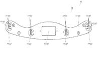
図11は、衣類保持部材300を示す図である。衣類保持部材300は、例えばステンレス鋼(SUS304)から成り、断面形状は直径5mmの円形状である。   FIG. 11 is a diagram showing the clothing holding member 300. The clothes holding member 300 is made of, for example, stainless steel (SUS304), and has a circular cross section with a diameter of 5 mm.

衣類保持部材300は、2つの長辺308と2つの短辺309の2つの辺からなる略長方形の形状である。1つの長辺308の長さは350mmであり、1つの短辺309の長さは40mmである。この長辺308と短辺309の長さは一例であり、長辺308と短辺309の長さを図11に示す長さと異なる数値としても良い。   The clothes holding member 300 has a substantially rectangular shape including two long sides 308 and two short sides 309. The length of one long side 308 is 350 mm, and the length of one short side 309 is 40 mm. The lengths of the long side 308 and the short side 309 are merely examples, and the length of the long side 308 and the short side 309 may be different from the length shown in FIG.

衣類保持部材300の4つの隅部分は曲面となっている。これは、衣類保持部材300が支持部材を支点に回転する際に、スムーズに回転できるようにするためである。   The four corners of the clothing holding member 300 are curved. This is to allow the clothing holding member 300 to rotate smoothly when rotating about the support member.

衣類保持部材300の1つの長辺308には、衣類がすべり落ちることを防止するための滑り止め317が形成されている。この滑り止め317は、例えば、熱可塑性エラストマーのような、衣類と滑り止め間に摩擦が生じ易い材料からなる。   On one long side 308 of the clothing holding member 300, a non-slip 317 for preventing the clothing from sliding down is formed. The non-slip 317 is made of a material such as a thermoplastic elastomer, which easily causes friction between the garment and the non-slip.

尚、この滑り止め317は2つの長辺308夫々に形成しても良いし、片方の長辺308のみに形成しても良い。   The anti-slip 317 may be formed on each of the two long sides 308, or may be formed on only one of the long sides 308.

図12は、右支持部301近傍を拡大した図である。図13は、使用者がリリースボタン307を押下した状態での、右支持部301近傍を拡大した図である。図12と図13の点線で示した部分はロック装置310であり、衣類保持部材300を支持或いは開放するための装置である。使用者は、このロック装置310に形成されたリリースボタン307を押下することにより、衣類保持部材300を右支持部301から開放することができる。   FIG. 12 is an enlarged view of the vicinity of the right support portion 301. FIG. 13 is an enlarged view of the vicinity of the right support portion 301 when the user presses the release button 307. A portion indicated by a dotted line in FIGS. 12 and 13 is a lock device 310, which is a device for supporting or opening the clothing holding member 300. The user can release the clothing holding member 300 from the right support portion 301 by pressing the release button 307 formed on the lock device 310.

図12に示すように、右支持部301は2つの内壁である外側内壁311と内側内壁312を有しており、これら内壁の上方には曲部313が形成されている。外側内壁311は下方に向けて多少傾斜しており、その長さは約8mmである。このため、使用者が左指示部のリリースボタン307を押下し、衣類保持部材300が図9に示すように左支持部302材を支点として回転する際に、約110度の回転角度まで回転し、衣類保持部材300がそれ以上の角度まで回転できないようになっている。   As shown in FIG. 12, the right support portion 301 has two inner walls, an outer inner wall 311 and an inner inner wall 312. Above these inner walls, a curved portion 313 is formed. The outer inner wall 311 is slightly inclined downward, and its length is about 8 mm. For this reason, when the user presses the release button 307 of the left instruction unit and the clothing holding member 300 rotates around the left support portion 302 as a fulcrum as shown in FIG. In addition, the clothing holding member 300 cannot be rotated to a further angle.

尚、本実施例では外側内壁311の長さを約8mmとしたが、他の長さとしても良い。例えば、4mm〜15mmの範囲での長さにすることも可能である。   In this embodiment, the length of the outer inner wall 311 is set to about 8 mm, but may be set to another length. For example, the length can be set in a range of 4 mm to 15 mm.

衣類保持部材300の回転角度は、設計時にこの外側内壁311の傾斜角度と長さを変更することにより変えることができる。   The rotation angle of the clothes holding member 300 can be changed by changing the inclination angle and length of the outer inner wall 311 at the time of design.

曲部313は表面が曲面である。このため、衣類保持部材300が回転しやすい構造となっている。   The curved portion 313 has a curved surface. For this reason, the clothes holding member 300 has a structure that is easy to rotate.

ロック装置310は下方に突出部314を有しており、ロック装置310は図示しないスプリング等の弾性部材により脱臭ハンガー10の外側(図13中右側)に向けて付勢されている。図12に示す状態では、突出部314は2つの内壁である、外側内壁311と内側内壁312と間の空間に突出し、衣類保持部材300が下方に落ちないように支持している。   The lock device 310 has a projecting portion 314 below, and the lock device 310 is urged toward the outside (the right side in FIG. 13) of the deodorizing hanger 10 by an elastic member such as a spring (not shown). In the state shown in FIG. 12, the protruding portion 314 protrudes into the space between the two inner walls, the outer inner wall 311 and the inner inner wall 312, and supports the clothing holding member 300 so as not to fall down.

使用者がリリースボタン307を押下すると、図13に示すように突出部314は、弾性部材の付勢力に抗して脱臭ハンガー10の内側(図13中左側)に移動する。そうすると、突出部314は衣類保持部材300を保持しなくなる。このため、衣類保持部材300は下方に落下する。   When the user presses the release button 307, as shown in FIG. 13, the protrusion 314 moves inside the deodorizing hanger 10 (left side in FIG. 13) against the urging force of the elastic member. Then, the protrusion 314 does not hold the clothing holding member 300. For this reason, the clothes holding member 300 falls downward.

図14は、右支持部301近傍を拡大し下方から見た斜視図である。   FIG. 14 is an enlarged perspective view of the vicinity of the right support portion 301 as viewed from below.

図14において、右支持部301のリリースボタン307が配置された右側側面305には、右側側面305の表面からへこんだ形状である凹部315が形成されている。この凹部315は、右支持部301が下部先端側通気部75を塞ぐことを極力回避している。   In FIG. 14, a concave portion 315 having a concave shape from the surface of the right side surface 305 is formed in the right side surface 305 of the right support portion 301 where the release button 307 is arranged. The concave portion 315 prevents the right support portion 301 from blocking the lower end side ventilation portion 75 as much as possible.

また、右側側面305の下方側には、複数の突部からなる凹凸部316が形成されている。この凹凸部316は、右側側面305の下方部分の強度を上げるためのものである。   An uneven portion 316 including a plurality of protrusions is formed below the right side surface 305. The uneven portion 316 is for increasing the strength of a lower portion of the right side surface 305.

より詳細には、衣類保持部材300が回転する際に、右側側面305の下方側に衣類保持部材300が当たり、右側側面305の下方側に衝撃が加わるが、このように衝撃が加わる部分に複数の突部からなる凹凸部316を形成し、強度を上げている。   More specifically, when the clothes holding member 300 rotates, the clothes holding member 300 hits the lower side of the right side surface 305, and an impact is applied to the lower side of the right side surface 305. The protrusions 316 are formed to increase the strength.

このように、右側側面305は、凹部315を有することにより、下部先端側通気部75からの脱臭成分が効率よく衣服に流れるようにしており、また、この凹部315の中に複数の突部からなる凹凸部316を有することにより、右支持部301の強度を高めている。   As described above, the right side surface 305 has the concave portion 315 so that the deodorizing component from the lower tip side ventilation portion 75 can efficiently flow into the clothes, and the concave portion 315 has a plurality of protrusions. By having the uneven portion 316 formed, the strength of the right support portion 301 is increased.

尚、左支持部302は右支持部301と同様な構成となっているため、説明を省略する。   Note that the left support portion 302 has the same configuration as the right support portion 301, and a description thereof will be omitted.

図15は、脱臭ハンガー10にズボンを掛けた状態を示す斜視図である。図16は、脱臭ハンガー10にズボンを掛けた状態を示す右側面図である。尚、点線で記載した部分がズボンである。   FIG. 15 is a perspective view showing a state in which pants are hung on the deodorizing hanger 10. FIG. 16 is a right side view showing a state in which pants are hung on the deodorizing hanger 10. The portion indicated by the dotted line is the pants.

図15、図16に示すように、衣類保持部材300の2つの長辺308にズボンを掛けているため、下部中心側通気部78から放出した消臭成分は、図16の矢印に示すように衣類保持部材300の下方から左右に向い流れる。このため、消臭成分をズボン全体に流すことが可能となる。   As shown in FIGS. 15 and 16, since the pants are hung on the two long sides 308 of the clothing holding member 300, the deodorant component released from the lower center side ventilation portion 78 is, as shown by the arrow in FIG. It flows right and left from below the clothing holding member 300. For this reason, it becomes possible to make the deodorant component flow through the entire pants.

衣類保持部材300にはスカートの紐を通すこともできる。スカートの紐の輪の中に衣類保持部材300を通し、衣類保持部材300を右支持部301と左支持部302に装着することにより、スカートを脱臭ハンガー10に吊り下げることが可能である。   A skirt string can be passed through the clothing holding member 300. The skirt can be hung on the deodorizing hanger 10 by passing the clothing holding member 300 through the loop of the skirt and attaching the clothing holding member 300 to the right support portion 301 and the left support portion 302.

尚、実施の形態3については、変形例として以下の構成とすることも可能である。   The third embodiment may have the following configuration as a modification.

本実施の形態3では、右支持部301と左支持部302は脱臭ハンガー10の本体に固定されているが、着脱可能としても良い。   In the third embodiment, the right support part 301 and the left support part 302 are fixed to the main body of the deodorizing hanger 10, but may be detachable.

また、本実施の形態3では、衣類保持部材300は、右支持部301と左支持部302から着脱可能であるが、衣類保持部材300を右支持部301と左支持部302に固定した構成としても良い。   In addition, in the third embodiment, the clothing holding member 300 is detachable from the right support portion 301 and the left support portion 302. However, the clothing holding member 300 is fixed to the right support portion 301 and the left support portion 302. Is also good.

また、本実施の形態3では、衣類保持部材300は、2つの長辺308を有しているが、1つの長辺308のみ、即ち略棒状の形状としても良い。   In addition, in the third embodiment, the clothing holding member 300 has two long sides 308, but may have only one long side 308, that is, a substantially rod shape.

また、衣類保持部材300の2つの長辺308の間にメッシュ状の部材を配置しても良い。このような構成とすることにより、衣類が衣類保持部材300からずり落ちるにくくすることができる。   Further, a mesh-like member may be arranged between the two long sides 308 of the clothing holding member 300. With such a configuration, it is possible to make it difficult for clothing to slip off from clothing holding member 300.

また、衣類保持部材300と滑り止め317を同じ材料で形成しても良い。例えば衣類保持部材300と滑り止め317をポリエチレンテレフタラートのような樹脂で形成し、滑り止め317部分に凹凸を形成し、他の部分は表面が滑りやすいように凹凸がない表面にすることで、滑り止め317部分により衣類がずり落ちることを防止することも可能である。   Further, the clothes holding member 300 and the slip stopper 317 may be formed of the same material. For example, by forming the clothes holding member 300 and the non-slip 317 with a resin such as polyethylene terephthalate, forming irregularities on the non-slip 317 portion, and forming the other portions to have a surface without irregularities so that the surface is slippery. It is also possible to prevent the clothes from slipping down by the non-slip part 317.

(変形例)
上記各実施の形態では、脱臭ハンガーが取り得る形態の一例について説明したが、上記
実施の形態に限られない。
(Modification)
In each of the above embodiments, an example of a form that the deodorizing hanger can take has been described, but the present invention is not limited to the above embodiments.

つまり、本実施の形態の脱臭ハンガーは、上記各実施の形態以外に、例えば以下に示す実施の形態の変形例、および、相互に矛盾しない少なくとも2つの変形例が組み合わせられた形態をも取り得る。   In other words, the deodorizing hanger of the present embodiment can take, in addition to the above-described embodiments, for example, a modification of the following embodiment, and a form in which at least two modifications that do not contradict each other are combined. .

具体的には、脱臭装置26が生成する脱臭成分の重さは、任意に変更可能である。例えば、脱臭装置26は、空気よりも重い脱臭成分を生成することもできる。この場合、通気部70が脱臭装置26よりもハンガー部20の上部21寄りの部分に設けられた第1通気部71、および、脱臭装置26よりもハンガー部20の底部22寄りの部分に設けられた第2通気部72を含むように構成することが好ましい。これにより、脱臭成分を含む空気が、貯留部44に流れ込みやすくなる。つまり、脱臭成分を含んだ空気は、主に第2通気部72を通過してハンガー部20の外部に移動する。そのため、ハンガー部20の外部から第1通気部71を通過して脱臭装置に流れる空気と、脱臭装置26により生成された脱臭成分の流れとの干渉が生じにくい。その結果、脱臭成分を、ハンガー部20の外部に効率的に放出できる。   Specifically, the weight of the deodorizing component generated by the deodorizing device 26 can be arbitrarily changed. For example, the deodorizing device 26 can generate a deodorizing component heavier than air. In this case, the ventilation portion 70 is provided at a portion closer to the upper portion 21 of the hanger portion 20 than the deodorizing device 26, and at a portion closer to the bottom portion 22 of the hanger portion 20 than the deodorizing device 26. It is preferable to include the second ventilation portion 72. This makes it easier for the air containing the deodorizing component to flow into the storage section 44. That is, the air containing the deodorizing component mainly moves through the second ventilation part 72 to the outside of the hanger part 20. Therefore, interference between the air flowing from the outside of the hanger section 20 through the first ventilation section 71 to the deodorizing device and the flow of the deodorizing component generated by the deodorizing device 26 does not easily occur. As a result, the deodorizing component can be efficiently released to the outside of the hanger section 20.

本発明の脱臭ハンガーは、帯電微粒子水、空気イオン、および、オゾンなどの脱臭成分を効率的に発生させて、衣類を脱臭することができる。そのため、脱臭ハンガー以外に、脱臭機能が要望される、家庭用、産業用などの機器に適用できる。   ADVANTAGE OF THE INVENTION The deodorizing hanger of this invention can generate | occur | produce deodorizing components, such as charged fine particle water, air ion, and ozone, efficiently, and can deodorize clothing. Therefore, in addition to the deodorizing hanger, the present invention can be applied to household and industrial equipment requiring a deodorizing function.

10 脱臭ハンガー
11 フック部
12 基端
20 ハンガー部
21 上部
22 底部
23 表示部
24 操作部
24A ボタン
25 端子部
26 脱臭装置
27 制御部
28 電動ファン
28A 吸込口
28B 吐出口
30 上部コンポーネント
31 フランジ
40 ハンガー部本体
41 開口部
42 流通路
43 通路部
44 貯留部
50 ネック部
51 上部
52 下部
60 アーム部
61 底部
62 先端部
63 中心
70 通気部
71 第1通気部
71A スリット
72 第2通気部
73 先端側通気部
74 上部先端側通気部
74A 第1上部先端側通気部
74B 第2上部先端側通気部
75 下部先端側通気部
76 中心側通気部
77 上部中心側通気部
78 下部中心側通気部
100 衣類
101 襟
102 肩
103 袖
300 衣類保持部材
301 右支持部
302 左支持部
303 右傾斜部
304 左傾斜部
305 右側側面
306 左側側面
307 リリースボタン
308 長辺
309 短辺
310 ロック装置
311 外側内壁
312 内側内壁
313 曲部
314 突出部
315 凹部
316 凹凸部
317 滑り止め
DESCRIPTION OF SYMBOLS 10 Deodorizing hanger 11 Hook part 12 Base end 20 Hanger part 21 Upper part 22 Bottom part 23 Display part 24 Operation part 24A Button 25 Terminal part 26 Deodorizing device 27 Control part 28 Electric fan 28A Suction port 28B Discharge port 30 Upper component 31 Flange 40 Hanger part Main body 41 Opening part 42 Flow path 43 Passage part 44 Storage part 50 Neck part 51 Upper part 52 Lower part 60 Arm part 61 Bottom part 62 Tip part 63 Center 70 Vent part 71 First vent part 71A Slit 72 Second vent part 73 Tip side vent part 74 Upper tip side ventilation part 74A First upper tip side ventilation part 74B Second upper tip side ventilation part 75 Lower tip side ventilation part 76 Center side ventilation part 77 Upper center side ventilation part 78 Lower center side ventilation part 100 Clothing 101 Collar 102 Shoulder 103 Sleeve 300 Clothing holding member 301 Right support Part 302 Left support part 303 Right inclined part 304 Left inclined part 305 Right side 306 Left side 307 Release button 308 Long side 309 Short side 310 Lock device 311 Outer inner wall 312 Inner inner wall 313 Curved part 314 Projection 315 Concave part 316 Uneven part 317 Sliding Stop

Claims (5)

上着をかけることが可能なハンガー部と、
前記ハンガー部内に設けられ、空気から脱臭成分を生成する脱臭装置と、を備え、
前記ハンガー部は、前記ハンガー部の外部および内部の一方から他方に空気が通過できるように構成される通気部を含み、
前記通気部は、少なくとも前記ハンガー部の底面に設けられ、
前記通気部の下方には、衣類保持部材が配置され、
前記ハンガー部の左右両側には、左支持部と右支持部が設けられ、
前記左支持部と前記右支持部には、それぞれ前記衣類保持部材を着脱自在に支持するためのロック装置が設けられている、脱臭ハンガー。
A hanger that can be worn with a jacket,
A deodorizing device that is provided in the hanger portion and generates a deodorizing component from air,
The hanger portion includes a ventilation portion configured to allow air to pass from one of the outside and the inside of the hanger portion to the other,
The ventilation portion is provided at least on a bottom surface of the hanger portion,
A clothing holding member is arranged below the ventilation section,
A left support portion and a right support portion are provided on both left and right sides of the hanger portion,
A deodorizing hanger, wherein the left support portion and the right support portion each include a lock device for detachably supporting the clothing holding member.
前記右支持部と前記左支持部は、2つの内壁を有し、前記衣類保持部材が前記右支持部又は前記左支持部により支持された状態で、前記衣類保持部材の一部は前記2つの内壁間に位置し、前記2つの内壁の内、脱臭ハンガーの外側に位置する内壁により、前記衣類保持部材の回転角度が規制される、請求項1に記載の脱臭ハンガー。   The right support portion and the left support portion have two inner walls, and in a state where the clothing holding member is supported by the right support portion or the left support portion, a part of the clothing holding member is the two The deodorizing hanger according to claim 1, wherein a rotation angle of the clothing holding member is regulated by an inner wall located between the inner walls and located outside the deodorizing hanger among the two inner walls. 前記右支持部と前記左支持部は、2つの内壁を有し、前記衣類保持部材が前記右支持部又は前記左支持部により支持された状態で、前記衣類保持部材の一部は前記2つの内壁間に位置し、前記2つの内壁の内、脱臭ハンガーの内側に位置する内壁には、前記衣類保持部材の一部が下方に落下することを防止するための突出部が配置され、前記ロック装置の一部が前記突出部である、請求項1又は2に記載の脱臭ハンガー。   The right support portion and the left support portion have two inner walls, and in a state where the clothing holding member is supported by the right support portion or the left support portion, a part of the clothing holding member is the two On the inner wall located between the inner walls and inside the deodorizing hanger, of the two inner walls, a protruding portion for preventing a part of the clothing holding member from falling down is arranged, and the lock is provided. The deodorizing hanger according to claim 1, wherein a part of the device is the protrusion. 前記右支持部と前記左支持部は、脱臭ハンガーの内側に傾斜部を有する請求項1〜3のいずれか1項に記載の脱臭ハンガー。   The deodorizing hanger according to any one of claims 1 to 3, wherein the right supporting portion and the left supporting portion have an inclined portion inside the deodorizing hanger. 前記右支持部と前記左支持部は、脱臭ハンガーの外側に位置する側面を有し、前記側面には、前記衣類保持手段の支持状態から非支持状態へと変えるためのリリースボタンが配されている、請求項1〜4のいずれか1項に記載の脱臭ハンガー。   The right support portion and the left support portion have side surfaces located outside a deodorizing hanger, and the side surface is provided with a release button for changing the clothes holding unit from a support state to a non-support state. The deodorizing hanger according to claim 1.
JP2018145500A 2018-08-02 2018-08-02 Deodorizing hanger Pending JP2020018655A (en)

Priority Applications (2)

Application Number Priority Date Filing Date Title
JP2018145500A JP2020018655A (en) 2018-08-02 2018-08-02 Deodorizing hanger
CN201910646666.7A CN110786707A (en) 2018-08-02 2019-07-17 Deodorizing clothes hanger

Applications Claiming Priority (1)

Application Number Priority Date Filing Date Title
JP2018145500A JP2020018655A (en) 2018-08-02 2018-08-02 Deodorizing hanger

Publications (1)

Publication Number Publication Date
JP2020018655A true JP2020018655A (en) 2020-02-06

Family

ID=69587441

Family Applications (1)

Application Number Title Priority Date Filing Date
JP2018145500A Pending JP2020018655A (en) 2018-08-02 2018-08-02 Deodorizing hanger

Country Status (1)

Country Link
JP (1) JP2020018655A (en)

Citations (7)

* Cited by examiner, † Cited by third party
Publication number Priority date Publication date Assignee Title
JPS58145146U (en) * 1982-03-23 1983-09-30 金澤 節 Clothes hanger
JPH0736857U (en) * 1993-12-24 1995-07-11 晃 平野 Hanger
US6149038A (en) * 2000-03-11 2000-11-21 Tsai; Sam Suit hanger with air freshener
JP2003509144A (en) * 1999-09-16 2003-03-11 ハーヅ インターナショナル,インコーポレーテッド Ozone generator
US7320182B1 (en) * 2006-09-15 2008-01-22 Tsang-Hung Hsu Dehumidifying hanger
JP3168767U (en) * 2011-03-28 2011-06-30 日本コパック株式会社 Hanger
CN204825437U (en) * 2015-07-28 2015-12-02 宁波科派尔电器有限公司 Clothes hanger of function of disinfecting

Patent Citations (7)

* Cited by examiner, † Cited by third party
Publication number Priority date Publication date Assignee Title
JPS58145146U (en) * 1982-03-23 1983-09-30 金澤 節 Clothes hanger
JPH0736857U (en) * 1993-12-24 1995-07-11 晃 平野 Hanger
JP2003509144A (en) * 1999-09-16 2003-03-11 ハーヅ インターナショナル,インコーポレーテッド Ozone generator
US6149038A (en) * 2000-03-11 2000-11-21 Tsai; Sam Suit hanger with air freshener
US7320182B1 (en) * 2006-09-15 2008-01-22 Tsang-Hung Hsu Dehumidifying hanger
JP3168767U (en) * 2011-03-28 2011-06-30 日本コパック株式会社 Hanger
CN204825437U (en) * 2015-07-28 2015-12-02 宁波科派尔电器有限公司 Clothes hanger of function of disinfecting

Similar Documents

Publication Publication Date Title
US20110268625A1 (en) Garment bag
WO2019131468A1 (en) Device for blowing airflow
JP2016047115A (en) Futon dryer
WO2016180370A1 (en) Clothes treating device
US20150202340A1 (en) Scent Dispenser System
JP2020018655A (en) Deodorizing hanger
JP2020018656A (en) Deodorizing hanger
BRPI0707921A2 (en) &#34;clothes hanger and clothes usage method
KR101639063B1 (en) The styler with blower of foldable hanger
JPWO2018159313A1 (en) Deodorant hanger
US20110194981A1 (en) Ozone device for deodorizing dresses
WO2016188404A1 (en) Clothing treatment device
CN110786707A (en) Deodorizing clothes hanger
JP2016093368A (en) Clothing treatment apparatus
JP2018053416A (en) Intra-garment environment cooling apparatus
JPH08228851A (en) Deodorizing device for clothes by using ozone
KR20160146479A (en) A foldable hanger with blower, the styler and the method using the same
KR101972259B1 (en) Apparatus for processing clothes
CN114502890A (en) Electric deodorizing machine
US20040140281A1 (en) Device for hanging towels
JP2004008139A (en) Fan-type insect-proofing apparatus
JP6570307B2 (en) Clothing processing equipment
KR200223521Y1 (en) Coat hanger for emitting fragrance
JP2010063811A (en) Portable medical equipment for hygiene agent
KR101962688B1 (en) Removable direction and dehumidification cover for hangers

Legal Events

Date Code Title Description
RD01 Notification of change of attorney

Free format text: JAPANESE INTERMEDIATE CODE: A7421

Effective date: 20190124

A621 Written request for application examination

Free format text: JAPANESE INTERMEDIATE CODE: A621

Effective date: 20210113

A977 Report on retrieval

Free format text: JAPANESE INTERMEDIATE CODE: A971007

Effective date: 20211029

A131 Notification of reasons for refusal

Free format text: JAPANESE INTERMEDIATE CODE: A131

Effective date: 20211130

A02 Decision of refusal

Free format text: JAPANESE INTERMEDIATE CODE: A02

Effective date: 20220524