JP2020008761A - Tracking roller and injection molding method thereof - Google Patents
Tracking roller and injection molding method thereof Download PDFInfo
- Publication number
- JP2020008761A JP2020008761A JP2018130767A JP2018130767A JP2020008761A JP 2020008761 A JP2020008761 A JP 2020008761A JP 2018130767 A JP2018130767 A JP 2018130767A JP 2018130767 A JP2018130767 A JP 2018130767A JP 2020008761 A JP2020008761 A JP 2020008761A
- Authority
- JP
- Japan
- Prior art keywords
- peripheral surface
- outer peripheral
- groove
- inner peripheral
- groove portion
- Prior art date
- Legal status (The legal status is an assumption and is not a legal conclusion. Google has not performed a legal analysis and makes no representation as to the accuracy of the status listed.)
- Granted
Links
Images


Abstract
Description
この発明は、電子転写方式の画像形成装置に備わる感光ドラムと現像ローラ間の距離を一定に保つために使用されるトラッキングローラ、及びそのトラッキングローラを射出成形する方法に関する。 The present invention relates to a tracking roller used for maintaining a constant distance between a photosensitive drum and a developing roller provided in an electronic transfer type image forming apparatus, and a method of injection molding the tracking roller.
電子転写方式の複写機、プリンタ等の画像形成装置に備わる現像ローラは、感光ドラムと一定の距離を保持して対向させなければならない。このため、現像ローラの同軸上にトラッキングローラを設け、トラッキングローラを感光ドラム表面に接触させて一定の距離を保持する構造が採用されている(例えば、特許文献1、2)。 A developing roller provided in an image forming apparatus such as a copying machine and a printer of an electronic transfer system must be opposed to the photosensitive drum while maintaining a certain distance. For this reason, a structure is employed in which a tracking roller is provided coaxially with the developing roller, and the tracking roller is brought into contact with the surface of the photosensitive drum to maintain a constant distance (for example, Patent Documents 1 and 2).
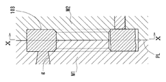
この種のトラッキングローラ100は、図5、図6に示すように、感光ドラムDの外周に接触する外周面101と、現像ローラRの軸部r1に嵌る内周面102とを一体に有する単一の環状体からなる。感光ドラムDは、露光装置(図示省略)によって静電潜像を形成可能な外周面を有する。現像ローラRは、現像剤を感光ドラムの現像領域に搬送可能な外周面と、現像ローラRの回転中心となる軸部r1とを有する。軸部r1は、感光ドラムDの回転軸と平行な向きに設けられる。現像ローラRは、軸部r1に取り付けられたギアGに伝達される駆動力によって回転させられる。トラッキングローラ100は、内周面102と軸部r1との嵌合によって現像ローラRと同軸に配置される。軸部r1は、トラッキングローラ100の外周面101を感光ドラムDの外周面に押し付ける方向に付勢されている。トラッキングローラ100は、感光ドラムDと現像ローラRとの間の距離を一定に保持すると共に、感光ドラムDに接触する状態で回転可能になっている。
As shown in FIGS. 5 and 6, this type of
電子転写方式の画像形成装置では、感光ドラムDの外周面が、帯電ローラ(図示省略)の電圧印加によって一様にマイナス帯電させられる。帯電された感光ドラムDの外周面上には、画像情報に基づいて制御される露光装置の露光によって静電潜像が形成される。現像ローラRには予め現像バイアスが印加されている。感光ドラムD上の前述の潜像は、造影剤を保持する状態で回転駆動される現像ローラRとの対向位置を通過する際にトナーで現像され、トナー像として可視化される。感光ドラムD上のトナー像は、転写手段(図示省略)によって記録紙に転写される。 In the electronic transfer type image forming apparatus, the outer peripheral surface of the photosensitive drum D is uniformly negatively charged by applying a voltage to a charging roller (not shown). An electrostatic latent image is formed on the outer peripheral surface of the charged photosensitive drum D by exposure of an exposure device controlled based on image information. A developing bias is applied to the developing roller R in advance. The above-described latent image on the photosensitive drum D is developed with toner when passing a position facing the developing roller R that is driven to rotate while holding the contrast agent, and is visualized as a toner image. The toner image on the photosensitive drum D is transferred to recording paper by a transfer unit (not shown).
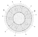
トラッキングローラ100は、図7、図8に示すように、径方向に沿った円環状の平坦面103を軸方向の両側に有する。これら両側の平坦面103は、円筒面状の外周面101に連続する。内周面102は、外周面101と同心の円筒面状である。内周面102と平坦面103との間は、面取り形状の隅部104になっている。すなわち、外周面101の軸方向一方側と内周面102の軸方向一方側との間に連続する第一及び第二の側面は、それぞれ平坦面103及び隅部104によって構成されている。
As shown in FIGS. 7 and 8, the
このようなトラッキングローラ100の製造方法として、合成樹脂の射出成形によってトラッキングローラ100の全体を一体に成形する射出成形方法が採用されている。この射出成形では、図9に示すように、軸方向に分割された金型M1,M2が用いられる。パーティングラインPLは、図7に示す外周面及び内周面の幅の中央位置に設定されている。図9、図10に示すように、一方の金型M1には、平坦面103を形成する金型部分に多点ピンポイントゲートgが設けられている。それら各ピンポイントゲートgから合成樹脂を射出することによって、図7に示すトラッキングローラ100の全体が一体に成形されている。このため、図8に示すように、一方の平坦面103は、ピンポイントゲートgに対応の位置に型開き時の切断部位(ゲート痕)105を有する。
As a method for manufacturing such a
しかしながら、図7、図8に示すトラッキングローラ100が前述のように射出成形される際、図9、図10に示すように、各ピンポイントゲートgから合成樹脂は、外周面101を転写する金型部分に直接流れる。このため、外周面101において、ウエルドwが発生する。そのウエルドwが凸または凹みになるため、外周面101の真円度が悪くなり、その外周面101を形成する肉部の肉厚差も大きくなる。これにより、図5に示す感光ドラムDと現像ローラR間の距離を一定に保つ精度が低下し、画像に濃淡差が出て画像不良となる懸念がある。
However, when the
上述の背景に鑑み、この発明が解決しようとする課題は、精度の良い外周面を有するトラッキングローラにすることである。 In view of the above background, an object to be solved by the present invention is to provide a tracking roller having a highly accurate outer peripheral surface.
上記の課題を達成するため、この発明は、感光ドラムに接触する外周面と、現像ローラの軸部に嵌る内周面とを一体に有するトラッキングローラにおいて、
前記外周面の軸方向一方側と前記内周面の軸方向一方側との間の位置で周方向全周に延びる第一溝部と、前記外周面の軸方向他方側と前記内周面の軸方向他方側との間の位置で周方向全周に延びる第二溝部とをさらに一体に有し、前記第一溝部と前記第二溝部が、互いに軸方向に対向する位置にあり、これら第一溝部と第二溝部間の肉厚が、0.3mm以上1.5mm以下であり、前記外周面の全面が、前記第一溝部に対して前記内周面側に配置されたピンポイントゲートから射出された合成樹脂によって成形されている構成を採用した。
In order to achieve the above object, the present invention provides a tracking roller integrally having an outer peripheral surface that contacts a photosensitive drum and an inner peripheral surface that fits into a shaft portion of a developing roller.
A first groove portion extending in the entire circumferential direction at a position between one axial side of the outer peripheral surface and one axial side of the inner peripheral surface; and an axis of the other axial side of the outer peripheral surface and the axis of the inner peripheral surface. A second groove portion extending in the entire circumferential direction at a position between the first groove portion and the second groove portion, and the first groove portion and the second groove portion are located at positions opposing each other in the axial direction. The thickness between the groove and the second groove is 0.3 mm or more and 1.5 mm or less, and the entire outer peripheral surface is ejected from a pinpoint gate disposed on the inner peripheral surface side with respect to the first groove. A configuration molded from the synthetic resin is adopted.
上記構成によれば、外周面の軸方向一方側と内周面の軸方向一方側間に位置する第一溝部と、外周面の軸方向他方側と内周面の軸方向他方側間に位置する第二溝部とが軸方向に対向し、これら溝部間の肉厚が薄い形状の場合、第一溝部に対して前記内周面側にピンポイントゲートを配置して合成樹脂を射出すると、射出された合成樹脂は、外周面側に充填されにくくなり、先ず、厚肉部となる内周面側に充填される。内周面側に充填された合成樹脂は、ウエルドが無くなった状態で第一溝部と第二溝部間を通って、ディスクゲートの様に外周面側に充填されることになる。すなわち、各ピンポイントゲートから流れた合成樹脂は、外周面側においてウエルドを形成するような合流を生じず、外周面上にウエルドが発生しなくなる。外周面上にウエルドが発生しないため、精度の良い外周面を有するトラッキングローラになる。ここで、第一溝部と第二溝部間の肉厚が0.3mm未満の場合、強度不足となる。一方、第一溝部と第二溝部間の肉厚が1.5mmを超える場合、合成樹脂が内周面側に充填された後に溝部間を通ってディスクゲートの様に外周面側へ流れる効果が得られない。 According to the above configuration, the first groove portion located between one axial side of the outer peripheral surface and one axial side of the inner peripheral surface, and the first groove portion located between the other axial side of the outer peripheral surface and the other axial side of the inner peripheral surface. When the second groove portion is axially opposed to the first groove portion and the thickness between these groove portions is thin, a pinpoint gate is arranged on the inner peripheral surface side with respect to the first groove portion to inject the synthetic resin. The synthetic resin thus obtained is less likely to be filled on the outer peripheral surface side, and is first filled on the inner peripheral surface side which is a thick portion. The synthetic resin filled on the inner peripheral surface side passes between the first groove portion and the second groove portion in a state where the weld is removed, and is filled on the outer peripheral surface side like a disk gate. That is, the synthetic resin flowing from each of the pinpoint gates does not join such that a weld is formed on the outer peripheral surface side, and no weld is generated on the outer peripheral surface. Since no weld is generated on the outer peripheral surface, the tracking roller has an accurate outer peripheral surface. Here, when the thickness between the first groove and the second groove is less than 0.3 mm, the strength is insufficient. On the other hand, when the thickness between the first groove portion and the second groove portion exceeds 1.5 mm, an effect of flowing to the outer peripheral surface side like a disk gate through the groove portion after the synthetic resin is filled into the inner peripheral surface side is obtained. I can't get it.
例えば、前記ピンポイントゲートの総数が3以上7以下である。 For example, the total number of the pinpoint gates is 3 or more and 7 or less.
例えば、前記外周面の直径が8mm以上20mm以下であり、前記内周面と前記第一溝部間、前記内周面と前記第二溝部間、前記外周面と前記第一溝部間、並びに前記外周面と前記第二溝部間の各間の最小間隔が、それぞれ0.5mm以上である。 For example, the diameter of the outer peripheral surface is 8 mm or more and 20 mm or less, and the inner peripheral surface and the first groove portion, the inner peripheral surface and the second groove portion, the outer peripheral surface and the first groove portion, and the outer periphery The minimum distance between each of the surface and the second groove is 0.5 mm or more.
例えば、前記外周面の真円度が、0μm以上10μm以下である。ただし真円度が0μmになることは皆無であるため、現実的には5μm以上10μm以下である。ここで、真円度は、日本工業規格(JIS B0621:1984)で規定された真円度のことをいう。 For example, the roundness of the outer peripheral surface is 0 μm or more and 10 μm or less. However, since the circularity never reaches 0 μm, it is practically 5 μm or more and 10 μm or less. Here, the roundness refers to the roundness defined by Japanese Industrial Standards (JIS B0621: 1984).
この発明を製造方法として考えると、感光ドラムに接触する外周面と、現像ローラの回転軸に嵌る内周面とを一体に有するトラッキングローラの射出成形方法において、前記外周面の軸方向一方側と前記内周面の軸方向一方側との間の位置で周方向全周に延びる第一溝部と、前記外周面の軸方向他方側と前記内周面の軸方向他方側との間の位置で周方向全周に延びる第二溝部とをさらに一体に有し、前記第一溝部と前記第二溝部が、互いに軸方向に対向する位置にあり、これら第一溝部と第二溝部間の肉厚が、0.3mm以上1.5mm以下であるように前記トラッキングローラを成形する金型を用い、前記第一溝部に対して前記内周面側を成形する金型部分に配置されたピンポイントゲートから合成樹脂を射出することによって前記外周面の全面を成形するトラッキングローラの射出成形方法に相当する。 Considering the present invention as a manufacturing method, in an injection molding method of a tracking roller integrally having an outer peripheral surface that comes into contact with the photosensitive drum and an inner peripheral surface that fits on the rotation shaft of the developing roller, A first groove extending in the entire circumferential direction at a position between the inner peripheral surface and one axial side, and a position between the other axial side of the outer peripheral surface and the other axial side of the inner peripheral surface; A second groove extending in the entire circumferential direction, the first groove and the second groove are located at positions axially opposed to each other, and the thickness between the first groove and the second groove is increased. A pin point gate disposed in a mold portion for molding the inner peripheral surface side with respect to the first groove portion using a mold for molding the tracking roller so that the distance is 0.3 mm or more and 1.5 mm or less. By injecting a synthetic resin from the Corresponding to the injection molding method of tracking rollers for molding the entire surface.
上述のように、この発明は、上記構成の採用により、射出成形の際に外周面上にウエルドが発生しないため、精度の良い外周面を有するトラッキングローラにすることができ、ひいては、感光ドラムと現像ローラ間の距離が精度よく一定に保たれるので、画像不良の発生を防止することができる。 As described above, according to the present invention, by adopting the above configuration, no weld is generated on the outer peripheral surface at the time of injection molding, so that a tracking roller having an accurate outer peripheral surface can be obtained. Since the distance between the developing rollers is accurately kept constant, it is possible to prevent image defects from occurring.
この発明の一例としての実施形態に係るトラッキングローラを添付図面に基づいて説明する。 A tracking roller according to an exemplary embodiment of the present invention will be described with reference to the accompanying drawings.
図1に示すトラッキングローラ1は、図5に示す従来例に代えて感光ドラムDと現像ローラR間の距離を一定に保つために使用されるものである(以下、感光ドラムD及び現像ローラRについては適宜に図5を参照のこと。)。 The tracking roller 1 shown in FIG. 1 is used instead of the conventional example shown in FIG. 5 to maintain a constant distance between the photosensitive drum D and the developing roller R (hereinafter, the photosensitive drum D and the developing roller R). Please refer to FIG. 5 as needed.)
ここで、軸方向とは、現像ローラRと同軸上にあるトラッキングローラ1の回転中心線に沿った方向のことをいう。また、その回転中心線に対して直角な方向のことを「径方向」という。また、その回転中心線周りの円周方向のことを「周方向」という。軸方向は、図1において左右方向に相当し、径方向は、図1において上下方向に相当する。 Here, the axial direction refers to a direction along the rotation center line of the tracking roller 1 which is coaxial with the developing roller R. The direction perpendicular to the rotation center line is referred to as “radial direction”. The circumferential direction around the rotation center line is referred to as “circumferential direction”. The axial direction corresponds to the horizontal direction in FIG. 1, and the radial direction corresponds to the vertical direction in FIG.
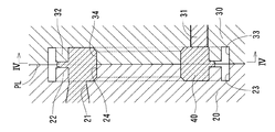
図1、図2に示すように、トラッキングローラ1は、感光ドラムDに接触する外周面2と、現像ローラRの軸部r1に嵌る内周面3と、両側面4,5とを一体に有する環状体からなる。
As shown in FIGS. 1 and 2, the tracking roller 1 integrally includes an outer
トラッキングローラ1の外周面2は、周方向全周に連続する円筒面状に成形されている。外周面2の直径D1は、トラッキングローラ1の外径に相当する。外周面2の直径D1は、例えば、8mm以上20mm以下である。
The outer
トラッキングローラ1の内周面3は、外周面2と同心の円筒面状に成形されている。内周面3は、トラッキングローラ1の内径を規定する部位となっている。
The inner
トラッキングローラ1の第一の側面4及び第二の側面5は、それぞれ周方向全周に延びる溝部6,9と、対応の溝部6,9と内周面3との間に連続する対応の内方の溝肩部7,10と、対応の溝部6,9と外周面2との間に連続する対応の外方の溝肩部8,11とを有する。
The
第一溝部6は、外周面2の軸方向一方側(図1中左側)と内周面3の軸方向一方側との間の位置で周方向全周に延びている。第一溝部6は、径方向に沿った溝底面と、軸方向に沿った平行一対の溝側面とで構成されている。第一溝部6は、周方向全周で一定の形状を有する。
The
第二溝部9は、外周面2の軸方向他方側(図1中右側)と内周面3の軸方向他方側との間の位置で周方向全周に延びている。第二溝部9は、径方向に沿った溝底面と、軸方向に沿った外方の溝側面と、外方の溝側面と向き合う内方の溝側面とで構成されている。第二溝部9は、周方向全周で第一溝部6と軸方向に対向する。
The
これら第一溝部6と第二溝部9間の肉厚tは、0.3mm以上1.5mm以下である。その肉厚tは、軸方向に対向する第一溝部6の溝底部分と第二溝部9の溝底部分間での軸方向の厚さに相当する。なお、第一溝部6と第二溝部9は、互いの溝幅の少なくとも一部分において軸方向に対向する位置関係にあればよい。
The thickness t between the
内方の溝肩部7,10は、それぞれ対応の第一溝部6又は第二溝部9に連続しかつ径方向に沿った平坦面と、内周面3に連続する隅部とを有する。その平坦面は、内方の溝肩部7,10の径方向長さにおける大部分の範囲に存在する。その隅部は、C面取りの場合を例示したが、R面取りにしてもよい。
Each of the
外方の溝肩部8,11は、それぞれ外周面2と対応の第一溝部6又は第二溝部9間の全域で径方向に沿った平坦面を有する。この平坦面は、周方向全周で同一の径方向長さを有する。
The
内周面3と第一溝部6間の最小肉厚tiは、0.5mm以上に設定されている。内周面3と第二溝部9間の最小肉厚tiは、内周面3と第一溝部6間の最小肉厚tiと同一に設定されている。これら最小肉厚tiは、内周面3と対応の第一溝部6又は第二溝部9間で最小となる径方向の厚さに相当する。
Minimum thickness t i between the inner
外周面2と第一溝部6間の最小肉厚toは、0.5mm以上に設定されている。外周面2と第二溝部9間の最小肉厚toは、外周面2と第一溝部6間の最小肉厚toと同一に設定されている。この最小肉厚toは、外周面2と対応の第一溝部6又は第二溝部9間で最小となる径方向の厚さに相当する。
Minimum thickness t o between the outer
また、最小肉厚to≦最小肉厚tiに設定されている。このため、トラッキングローラ1のうち、第一溝部6及び第二溝部9に対して内周面3側の環状部分は、第一溝部6及び第二溝部9に対して外周面2側の環状部分に比して径方向に等しいか厚い厚肉部となっている。
Further, the minimum thickness t o ≦ the minimum thickness t i is set. Therefore, in the tracking roller 1, the annular portion on the inner
外周面2の全面は、第一の内方の溝肩部7上に配置されたピンポイントゲート(図1中にゲート位置を三角マークで示す。)から射出された合成樹脂によって成形されている。このため、第一の内方の溝肩部7は、図2に示すように、ピンポイントゲートに対応の位置に型開き時の切断部位(ゲート痕)12を有する。図示では、ピンポイントゲートの総数を5として周方向に等配した例を示したが、ピンポイントゲートの総数は、例えば、3以上7以下である。トラッキングローラ1は、第一の内方の溝肩部7のみに切断部位(ゲート痕)12を有する。
The entire outer
トラッキングローラ1を形成する前述の合成樹脂として、例えば、ポリアミド(PA)、ポリアセタール(POM)、ポリエチレン(PE)、ポリフェニレンサルファイド(PPS)等が挙げられる。 Examples of the above-mentioned synthetic resin forming the tracking roller 1 include polyamide (PA), polyacetal (POM), polyethylene (PE), polyphenylene sulfide (PPS), and the like.
図3、図4に、トラッキングローラ1の射出成形に用いる金型20、30と、射出成形時の樹脂流動の様子を示す。図1、図3を対比すれば明らかなように、パーティングラインPLは、外周面2及び内周面3を軸方向に二等分する位置上に設定されている。固定側金型20は、多点配置されたピンポイントゲート21と、第一溝部6の形状を転写する第一のコア22と、外周面2の軸方向一方側の形状を転写する外方円周面23と、内周面3の軸方向一方側の形状を転写する内方円周面24とを有する。
3 and 4 show dies 20 and 30 used for injection molding of the tracking roller 1 and how the resin flows during the injection molding. 1 and 3, the parting line PL is set at a position that bisects the outer
ピンポイントゲート21は、固定側金型20と可動側金型30を開閉する方向(軸方向に相当)に開口し、その開口形状を円形としたゲート(溶融樹脂を金型のキャビティに注入する絞り孔)であり、ピンゲートとも呼ばれる。通常、ピンポイントゲート21の内径は、1mm前後である。各ピンポイントゲート21は、固定側金型20のうち、内方の溝肩部7を形成するキャビティ(すなわち、外方円周面23と内方円周面24とを繋ぐ側面領域)に配置されている。
The
可動側金型30は、多点配置されたエジェクタピン31と、第二溝部9の形状を転写するコア32と、外周面2の軸方向他方側の形状を転写する外方円周面33と、内周面3の軸方向他方側の形状を転写する内方円周面34とを有する。
The
第一の内方の溝肩部7上に配置されたピンポイントゲート21から射出される合成樹脂40は、第一溝部6と第二溝部9間の肉厚tが薄いため(すなわち、コア22,32間の隙間が狭いため)、外周面2側(すなわちコア22,32に対して外方円周面23,33側のキャビティ)への樹脂の流れが遅くなる。このため、射出された合成樹脂40は、外周面2側(外方円周面23,33側のキャビティ)に充填されにくくなり、先ず、厚肉部となる内周面3側(すなわち、コア22,32に対して内方円周面24,34側のキャビティ)に充填される。内周面3側(内方円周面24,34側のキャビティ)に充填された合成樹脂40は、図3、図4に示すように、ウエルドが無くなった状態で第一溝部6と第二溝部9間(コア22,32間の隙間)を通って、ディスクゲートの様に外周面2側(外方円周面23,33側のキャビティ)に充填され、外周面2の全面が成形されることになる。すなわち、各ピンポイントゲート21から流れた合成樹脂40は、外周面2側(外方円周面23,33側のキャビティ)においてウエルドを形成するような合流を生じず、外周面2上にウエルドが発生しなくなる。外周面2上にウエルドが発生しないため、精度の良い外周面2を有するトラッキングローラ1になる。
The
ここで、図1〜図4に示す実施形態において第一溝部6と第二溝部9間の肉厚t(コア22,32間の距離)を様々に変化させた試験結果を表1に示す。
Here, Table 1 shows test results obtained by variously changing the thickness t (the distance between the
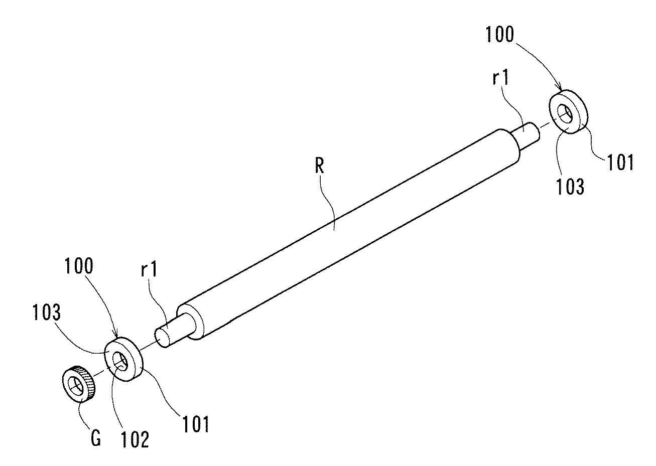
表1に示すように、第一溝部6と第二溝部9間の肉厚tが0.3mm未満の場合、第一溝部6と第二溝部9間が薄くなり過ぎ、当該部位の強度が不足した。
As shown in Table 1, when the thickness t between the
第一溝部6と第二溝部9間の肉厚t(コア22,32間の距離)が0.3mm以上、1.5mm以下の場合、トラッキングローラ1の強度不足が問題化せず、外周面2や外周面2と溝部6,9間の肉部においてウエルドが発生しなかった。このため、トラッキングローラ1における外周面2の真円度が、0μm以上10μm以下となり、外周面2を形成する部位の肉厚差が、0μm以上10μm以下となった。これに対し、第一溝部6及び第二溝部9を無くした点でのみ相違する比較例(図7〜図10に示す従来のトラッキングローラ100相当)では、外周面101の真円度が、約30μmとなり、外周面101を形成する部位での肉厚差が約20μmとなった。これら真円度、肉厚差の各値は、外周面の直径(最大直径)上での測定値である。その真円度は、日本工業規格(JIS B0621:1984)で規定されるように、円形形体の幾何学的に正しい円からの狂いの大きさのことをいい、円形形体を二つの同心の幾何学的円で挟んだとき、同心二円の間隔が最小となる場合の二円の半径の差で表される。
When the thickness t (the distance between the
第一溝部6と第二溝部9間の肉厚t(コア22,32間の距離)が1.5mmを超えると、外周面2上にウエルドが発生した。これは、合成樹脂40が内周面3側(内方円周面24,34側のキャビティ)に充填された後に第一溝部6と第二溝部9間(コア22,32間の隙間)を通ってディスクゲートの様に外周面2側(外方円周面23,33側のキャビティ)へ流れる効果が得られなかったためである。
When the thickness t (the distance between the
このように、実施形態によれば、外周面2の軸方向一方側と内周面3の軸方向一方側との間の位置で周方向全周に延びる第一溝部6と、外周面2の軸方向他方側と内周面3の軸方向他方側との間の位置で周方向全周に延びる第二溝部9とをさらに一体に有し、第一溝部6と第二溝部9が互いに軸方向に対向する位置にあり、これら第一溝部6と第二溝部9間の肉厚tが0.3mm以上1.5mm以下であり、外周面2の全面が、第一溝部6に対して内周面3側に配置されたピンポイントゲート21から射出された合成樹脂40によって成形されるので、射出成形の際に外周面2上にウエルドが発生しない。このため、実施形態に係るトラッキングローラ1及びその射出成形方法によれば、精度の良い外周面2を有するトラッキングローラ1にすることができ、ひいては、感光ドラムDと現像ローラR間の距離が精度よく一定に保たれるので、画像不良の発生を防止することができる。すなわち、外周面2の形状が良くなると、ウエルドの影響(外周面上のウエルドによる凹凸の影響)によって感光ドラムDと現像ローラR間の距離が変化することが防止されるため、画像の濃淡が出にくくなる。また、外周面2の真円度が良くなると、感光ドラムDと現像ローラR間の距離が回転位置に応じて変化することが防止されるため、1回転における画像の濃淡が出にくくなる。
Thus, according to the embodiment, the
今回開示された実施形態はすべての点で例示であって制限的なものではないと考えられるべきである。したがって、本発明の範囲は、特許請求の範囲によって示され、特許請求の範囲と均等の意味および範囲内でのすべての変更が含まれることが意図される。 The embodiments disclosed this time are to be considered in all respects as illustrative and not restrictive. Accordingly, the scope of the present invention is defined by the appended claims, and is intended to include any modifications within the scope and meaning equivalent to the appended claims.
1 トラッキングローラ
2 外周面
3 内周面
6 第一溝部
7 内方の溝肩部
9 第二溝部
20,30 金型
21 ピンポイントゲート
22,32 コア
23,33 外方円周面
24,34 内方円周面
40 合成樹脂
DESCRIPTION OF SYMBOLS 1
Claims (5)
前記外周面(2)の軸方向一方側と前記内周面(3)の軸方向一方側との間の位置で周方向全周に延びる第一溝部(6)と、前記外周面(2)の軸方向他方側と前記内周面(3)の軸方向他方側との間の位置で周方向全周に延びる第二溝部(9)とをさらに一体に有し、前記第一溝部(6)と前記第二溝部(9)が、互いに軸方向に対向する位置にあり、これら第一溝部(6)と第二溝部(9)間の肉厚(t)が、0.3mm以上1.5mm以下であり、前記外周面(2)の全面が、前記第一溝部(6)に対して前記内周面(3)側に配置されたピンポイントゲート(21)から射出された合成樹脂(40)によって成形されていることを特徴とするトラッキングローラ。 In a tracking roller integrally having an outer peripheral surface (2) contacting the photosensitive drum (D) and an inner peripheral surface (3) fitted on the shaft portion (r1) of the developing roller (R)
A first groove (6) extending all around in the circumferential direction at a position between one axial side of the outer peripheral surface (2) and one axial side of the inner peripheral surface (3); and the outer peripheral surface (2). A second groove (9) extending in the entire circumferential direction at a position between the other axial side of the inner peripheral surface (3) and the other axial side of the inner peripheral surface (3). ) And the second groove portion (9) are located at positions opposing each other in the axial direction, and the thickness (t) between the first groove portion (6) and the second groove portion (9) is not less than 0.3 mm. 5 mm or less, and the entire surface of the outer peripheral surface (2) is made of a synthetic resin injected from a pinpoint gate (21) disposed on the inner peripheral surface (3) side with respect to the first groove portion (6) ( 40) A tracking roller characterized by being formed by (40).
前記外周面(2)の軸方向一方側と前記内周面(3)の軸方向一方側との間の位置で周方向全周に延びる第一溝部(6)と、前記外周面(2)の軸方向他方側と前記内周面(3)の軸方向他方側との間の位置で周方向全周に延びる第二溝部(9)とをさらに一体に有し、前記第一溝部(6)と前記第二溝部(9)が、互いに軸方向に対向する位置にあり、これら第一溝部(6)と第二溝部(9)間の肉厚(t)が、0.3mm以上1.5mm以下であるように前記トラッキングローラ(1)を成形する金型(20,30)を用い、前記第一溝部(6)に対して前記内周面(3)側を成形する金型部分に配置されたピンポイントゲート(21)から合成樹脂(40)を射出することによって前記外周面(2)の全面を成形することを特徴とするトラッキングローラの射出成形方法。 In a tracking roller injection molding method, an outer peripheral surface (2) that comes into contact with the photosensitive drum (D) and an inner peripheral surface (3) that fits into a shaft portion (r1) of the developing roller (R) are integrated.
A first groove (6) extending all around in the circumferential direction at a position between one axial side of the outer peripheral surface (2) and one axial side of the inner peripheral surface (3); and the outer peripheral surface (2). A second groove (9) extending in the entire circumferential direction at a position between the other axial side of the inner peripheral surface (3) and the other axial side of the inner peripheral surface (3). ) And the second groove portion (9) are located at positions opposing each other in the axial direction, and the thickness (t) between the first groove portion (6) and the second groove portion (9) is not less than 0.3 mm. Using a mold (20, 30) for molding the tracking roller (1) so as to be 5 mm or less, a mold portion for molding the inner peripheral surface (3) side with respect to the first groove (6). The entire outer peripheral surface (2) is molded by injecting a synthetic resin (40) from the arranged pinpoint gate (21). Injection molding method of racking roller.
Priority Applications (1)
| Application Number | Priority Date | Filing Date | Title |
|---|---|---|---|
| JP2018130767A JP7022662B2 (en) | 2018-07-10 | 2018-07-10 | Tracking roller and its injection molding method |
Applications Claiming Priority (1)
| Application Number | Priority Date | Filing Date | Title |
|---|---|---|---|
| JP2018130767A JP7022662B2 (en) | 2018-07-10 | 2018-07-10 | Tracking roller and its injection molding method |
Publications (2)
| Publication Number | Publication Date |
|---|---|
| JP2020008761A true JP2020008761A (en) | 2020-01-16 |
| JP7022662B2 JP7022662B2 (en) | 2022-02-18 |
Family
ID=69151517
Family Applications (1)
| Application Number | Title | Priority Date | Filing Date |
|---|---|---|---|
| JP2018130767A Active JP7022662B2 (en) | 2018-07-10 | 2018-07-10 | Tracking roller and its injection molding method |
Country Status (1)
| Country | Link |
|---|---|
| JP (1) | JP7022662B2 (en) |
Citations (6)
| Publication number | Priority date | Publication date | Assignee | Title |
|---|---|---|---|---|
| JPH11102119A (en) * | 1997-09-26 | 1999-04-13 | Copyer Co Ltd | Image forming device |
| JP2005266540A (en) * | 2004-03-19 | 2005-09-29 | Fuji Xerox Co Ltd | Image forming method and image forming apparatus |
| JP2006070914A (en) * | 2004-08-31 | 2006-03-16 | Nidec Nissin Corp | Plastic gear |
| JP2007071925A (en) * | 2005-09-02 | 2007-03-22 | Fuji Xerox Co Ltd | Image forming apparatus |
| CN202362591U (en) * | 2011-11-30 | 2012-08-01 | 珠海天威飞马打印耗材有限公司 | Shaft sleeve and toner cartridge using same |
| JP2013210073A (en) * | 2012-03-30 | 2013-10-10 | Fuji Xerox Co Ltd | Rotating body and bearing |
-
2018
- 2018-07-10 JP JP2018130767A patent/JP7022662B2/en active Active
Patent Citations (6)
| Publication number | Priority date | Publication date | Assignee | Title |
|---|---|---|---|---|
| JPH11102119A (en) * | 1997-09-26 | 1999-04-13 | Copyer Co Ltd | Image forming device |
| JP2005266540A (en) * | 2004-03-19 | 2005-09-29 | Fuji Xerox Co Ltd | Image forming method and image forming apparatus |
| JP2006070914A (en) * | 2004-08-31 | 2006-03-16 | Nidec Nissin Corp | Plastic gear |
| JP2007071925A (en) * | 2005-09-02 | 2007-03-22 | Fuji Xerox Co Ltd | Image forming apparatus |
| CN202362591U (en) * | 2011-11-30 | 2012-08-01 | 珠海天威飞马打印耗材有限公司 | Shaft sleeve and toner cartridge using same |
| JP2013210073A (en) * | 2012-03-30 | 2013-10-10 | Fuji Xerox Co Ltd | Rotating body and bearing |
Also Published As
| Publication number | Publication date |
|---|---|
| JP7022662B2 (en) | 2022-02-18 |
Similar Documents
| Publication | Publication Date | Title |
|---|---|---|
| JP4229687B2 (en) | Injection molded resin gear, injection molded resin rotating body, and injection molded body | |
| KR101833100B1 (en) | Developing cartridge, process cartridge and image forming apparatus | |
| US9046823B2 (en) | Developer accommodating container and process cartridge | |
| US20110158707A1 (en) | Restricting blade and developing device | |
| JP3298880B2 (en) | Tape guide roller for tape cassette and method of manufacturing the same | |
| JP2020008761A (en) | Tracking roller and injection molding method thereof | |
| JP5832626B2 (en) | Method for manufacturing developer container and method for manufacturing process cartridge | |
| US10322580B2 (en) | Frame, cartridge, image forming apparatus, and method for manufacturing frame | |
| JP4893871B1 (en) | Bearing / sealing seal member, developing device and image forming apparatus using the same | |
| JP5049520B2 (en) | Method for producing elastic roller | |
| JP5382509B2 (en) | Rolling element for sheet conveyance of electrophotographic apparatus and injection molding die thereof | |
| JP5025344B2 (en) | Developing roller, electrophotographic process cartridge, and image forming apparatus | |
| JP5890109B2 (en) | Magnet roller mold | |
| JP4704122B2 (en) | Bearing member for image forming apparatus and bearing unit for image forming apparatus | |
| US11383413B2 (en) | Manufacturing method of polygonal mirror, polygonal mirror, deflector, optical scanning apparatus and image forming apparatus | |
| JP2010185943A (en) | Electrophotographic member, flange and cylindrical member | |
| JP2012098538A (en) | Photosensitive drum unit, process cartridge including photosensitive drum unit, and image forming apparatus | |
| JP2004074429A (en) | Mold for molding rubber roller and manufacturing method for rubber roller | |
| JP2000075529A (en) | Production of base body for photoreceptor drum | |
| JP6370335B2 (en) | Cartridge and unit manufacturing method | |
| JP2007041026A (en) | Conductive member, process cartridge and image forming apparatus | |
| JP5976151B2 (en) | Cartridge and image forming apparatus | |
| JP2006018061A (en) | Magnet roller | |
| JP5937393B2 (en) | Magnet roller mold | |
| JP4798896B2 (en) | Mold for magnet roller molding |
Legal Events
| Date | Code | Title | Description |
|---|---|---|---|
| A621 | Written request for application examination |
Free format text: JAPANESE INTERMEDIATE CODE: A621 Effective date: 20210317 |
|
| TRDD | Decision of grant or rejection written | ||
| A01 | Written decision to grant a patent or to grant a registration (utility model) |
Free format text: JAPANESE INTERMEDIATE CODE: A01 Effective date: 20220111 |
|
| A61 | First payment of annual fees (during grant procedure) |
Free format text: JAPANESE INTERMEDIATE CODE: A61 Effective date: 20220207 |
|
| R150 | Certificate of patent or registration of utility model |
Ref document number: 7022662 Country of ref document: JP Free format text: JAPANESE INTERMEDIATE CODE: R150 |