JP2020007977A - Compression self-ignition internal combustion engine - Google Patents
Compression self-ignition internal combustion engine Download PDFInfo
- Publication number
- JP2020007977A JP2020007977A JP2018129991A JP2018129991A JP2020007977A JP 2020007977 A JP2020007977 A JP 2020007977A JP 2018129991 A JP2018129991 A JP 2018129991A JP 2018129991 A JP2018129991 A JP 2018129991A JP 2020007977 A JP2020007977 A JP 2020007977A
- Authority
- JP
- Japan
- Prior art keywords
- layer
- passage
- internal combustion
- combustion engine
- combustion chamber
- Prior art date
- Legal status (The legal status is an assumption and is not a legal conclusion. Google has not performed a legal analysis and makes no representation as to the accuracy of the status listed.)
- Pending
Links
- 238000002485 combustion reaction Methods 0.000 title claims abstract description 161
- 230000006835 compression Effects 0.000 title claims abstract description 34
- 238000007906 compression Methods 0.000 title claims abstract description 34
- 239000000446 fuel Substances 0.000 claims abstract description 65
- 238000002347 injection Methods 0.000 claims abstract description 51
- 239000007924 injection Substances 0.000 claims abstract description 51
- 238000004891 communication Methods 0.000 claims description 14
- 210000000056 organ Anatomy 0.000 claims 1
- 230000014759 maintenance of location Effects 0.000 abstract 1
- 239000000243 solution Substances 0.000 abstract 1
- 239000000463 material Substances 0.000 description 37
- 230000000694 effects Effects 0.000 description 22
- 239000007921 spray Substances 0.000 description 16
- 239000007789 gas Substances 0.000 description 14
- MCMNRKCIXSYSNV-UHFFFAOYSA-N Zirconium dioxide Chemical group O=[Zr]=O MCMNRKCIXSYSNV-UHFFFAOYSA-N 0.000 description 12
- 239000000567 combustion gas Substances 0.000 description 12
- 238000010586 diagram Methods 0.000 description 9
- 239000011810 insulating material Substances 0.000 description 8
- 230000001629 suppression Effects 0.000 description 7
- 239000000203 mixture Substances 0.000 description 6
- 239000000779 smoke Substances 0.000 description 6
- 229910052581 Si3N4 Inorganic materials 0.000 description 5
- 238000000034 method Methods 0.000 description 5
- 238000012986 modification Methods 0.000 description 5
- 230000004048 modification Effects 0.000 description 5
- HQVNEWCFYHHQES-UHFFFAOYSA-N silicon nitride Chemical group N12[Si]34N5[Si]62N3[Si]51N64 HQVNEWCFYHHQES-UHFFFAOYSA-N 0.000 description 5
- XEEYBQQBJWHFJM-UHFFFAOYSA-N Iron Chemical compound [Fe] XEEYBQQBJWHFJM-UHFFFAOYSA-N 0.000 description 4
- 239000000919 ceramic Substances 0.000 description 4
- 238000010438 heat treatment Methods 0.000 description 4
- 230000002093 peripheral effect Effects 0.000 description 4
- VYPSYNLAJGMNEJ-UHFFFAOYSA-N Silicium dioxide Chemical compound O=[Si]=O VYPSYNLAJGMNEJ-UHFFFAOYSA-N 0.000 description 3
- 230000000052 comparative effect Effects 0.000 description 3
- 238000009434 installation Methods 0.000 description 3
- 238000002156 mixing Methods 0.000 description 3
- 230000002035 prolonged effect Effects 0.000 description 3
- 230000001105 regulatory effect Effects 0.000 description 3
- 229910052782 aluminium Inorganic materials 0.000 description 2
- XAGFODPZIPBFFR-UHFFFAOYSA-N aluminium Chemical compound [Al] XAGFODPZIPBFFR-UHFFFAOYSA-N 0.000 description 2
- 239000011324 bead Substances 0.000 description 2
- 239000011248 coating agent Substances 0.000 description 2
- 238000000576 coating method Methods 0.000 description 2
- 238000005520 cutting process Methods 0.000 description 2
- 238000000265 homogenisation Methods 0.000 description 2
- 239000012212 insulator Substances 0.000 description 2
- 229910052742 iron Inorganic materials 0.000 description 2
- 229910052751 metal Inorganic materials 0.000 description 2
- 239000002184 metal Substances 0.000 description 2
- 238000005507 spraying Methods 0.000 description 2
- 238000005728 strengthening Methods 0.000 description 2
- 238000007751 thermal spraying Methods 0.000 description 2
- 229910000838 Al alloy Inorganic materials 0.000 description 1
- XUIMIQQOPSSXEZ-UHFFFAOYSA-N Silicon Chemical compound [Si] XUIMIQQOPSSXEZ-UHFFFAOYSA-N 0.000 description 1
- GWEVSGVZZGPLCZ-UHFFFAOYSA-N Titan oxide Chemical compound O=[Ti]=O GWEVSGVZZGPLCZ-UHFFFAOYSA-N 0.000 description 1
- RTAQQCXQSZGOHL-UHFFFAOYSA-N Titanium Chemical compound [Ti] RTAQQCXQSZGOHL-UHFFFAOYSA-N 0.000 description 1
- QCWXUUIWCKQGHC-UHFFFAOYSA-N Zirconium Chemical compound [Zr] QCWXUUIWCKQGHC-UHFFFAOYSA-N 0.000 description 1
- 229910006501 ZrSiO Inorganic materials 0.000 description 1
- 238000007743 anodising Methods 0.000 description 1
- 230000003111 delayed effect Effects 0.000 description 1
- 239000000835 fiber Substances 0.000 description 1
- 239000011521 glass Substances 0.000 description 1
- 238000004519 manufacturing process Methods 0.000 description 1
- 239000012528 membrane Substances 0.000 description 1
- 230000003647 oxidation Effects 0.000 description 1
- 238000007254 oxidation reaction Methods 0.000 description 1
- 239000011148 porous material Substances 0.000 description 1
- 230000001737 promoting effect Effects 0.000 description 1
- 229910052710 silicon Inorganic materials 0.000 description 1
- 239000010703 silicon Substances 0.000 description 1
- 239000000377 silicon dioxide Substances 0.000 description 1
- 239000010936 titanium Substances 0.000 description 1
- 229910052719 titanium Inorganic materials 0.000 description 1
- RUDFQVOCFDJEEF-UHFFFAOYSA-N yttrium(III) oxide Inorganic materials [O-2].[O-2].[O-2].[Y+3].[Y+3] RUDFQVOCFDJEEF-UHFFFAOYSA-N 0.000 description 1
- 229910052845 zircon Inorganic materials 0.000 description 1
- 229910052726 zirconium Inorganic materials 0.000 description 1
- GFQYVLUOOAAOGM-UHFFFAOYSA-N zirconium(iv) silicate Chemical compound [Zr+4].[O-][Si]([O-])([O-])[O-] GFQYVLUOOAAOGM-UHFFFAOYSA-N 0.000 description 1
Images


Classifications
-
- F—MECHANICAL ENGINEERING; LIGHTING; HEATING; WEAPONS; BLASTING
- F02—COMBUSTION ENGINES; HOT-GAS OR COMBUSTION-PRODUCT ENGINE PLANTS
- F02B—INTERNAL-COMBUSTION PISTON ENGINES; COMBUSTION ENGINES IN GENERAL
- F02B23/00—Other engines characterised by special shape or construction of combustion chambers to improve operation
- F02B23/02—Other engines characterised by special shape or construction of combustion chambers to improve operation with compression ignition
- F02B23/06—Other engines characterised by special shape or construction of combustion chambers to improve operation with compression ignition the combustion space being arranged in working piston
- F02B23/0645—Details related to the fuel injector or the fuel spray
- F02B23/0648—Means or methods to improve the spray dispersion, evaporation or ignition
- F02B23/0651—Means or methods to improve the spray dispersion, evaporation or ignition the fuel spray impinging on reflecting surfaces or being specially guided throughout the combustion space
-
- F—MECHANICAL ENGINEERING; LIGHTING; HEATING; WEAPONS; BLASTING
- F02—COMBUSTION ENGINES; HOT-GAS OR COMBUSTION-PRODUCT ENGINE PLANTS
- F02B—INTERNAL-COMBUSTION PISTON ENGINES; COMBUSTION ENGINES IN GENERAL
- F02B77/00—Component parts, details or accessories, not otherwise provided for
- F02B77/02—Surface coverings of combustion-gas-swept parts
-
- F—MECHANICAL ENGINEERING; LIGHTING; HEATING; WEAPONS; BLASTING
- F02—COMBUSTION ENGINES; HOT-GAS OR COMBUSTION-PRODUCT ENGINE PLANTS
- F02M—SUPPLYING COMBUSTION ENGINES IN GENERAL WITH COMBUSTIBLE MIXTURES OR CONSTITUENTS THEREOF
- F02M61/00—Fuel-injectors not provided for in groups F02M39/00 - F02M57/00 or F02M67/00
- F02M61/16—Details not provided for in, or of interest apart from, the apparatus of groups F02M61/02 - F02M61/14
- F02M61/18—Injection nozzles, e.g. having valve seats; Details of valve member seated ends, not otherwise provided for
- F02M61/1806—Injection nozzles, e.g. having valve seats; Details of valve member seated ends, not otherwise provided for characterised by the arrangement of discharge orifices, e.g. orientation or size
-
- F—MECHANICAL ENGINEERING; LIGHTING; HEATING; WEAPONS; BLASTING
- F02—COMBUSTION ENGINES; HOT-GAS OR COMBUSTION-PRODUCT ENGINE PLANTS
- F02B—INTERNAL-COMBUSTION PISTON ENGINES; COMBUSTION ENGINES IN GENERAL
- F02B23/00—Other engines characterised by special shape or construction of combustion chambers to improve operation
- F02B23/02—Other engines characterised by special shape or construction of combustion chambers to improve operation with compression ignition
- F02B23/06—Other engines characterised by special shape or construction of combustion chambers to improve operation with compression ignition the combustion space being arranged in working piston
- F02B23/0645—Details related to the fuel injector or the fuel spray
- F02B23/0654—Thermal treatments, e.g. with heating elements or local cooling
-
- F—MECHANICAL ENGINEERING; LIGHTING; HEATING; WEAPONS; BLASTING
- F02—COMBUSTION ENGINES; HOT-GAS OR COMBUSTION-PRODUCT ENGINE PLANTS
- F02B—INTERNAL-COMBUSTION PISTON ENGINES; COMBUSTION ENGINES IN GENERAL
- F02B23/00—Other engines characterised by special shape or construction of combustion chambers to improve operation
- F02B23/02—Other engines characterised by special shape or construction of combustion chambers to improve operation with compression ignition
- F02B23/06—Other engines characterised by special shape or construction of combustion chambers to improve operation with compression ignition the combustion space being arranged in working piston
- F02B23/0672—Omega-piston bowl, i.e. the combustion space having a central projection pointing towards the cylinder head and the surrounding wall being inclined towards the cylinder center axis
-
- F—MECHANICAL ENGINEERING; LIGHTING; HEATING; WEAPONS; BLASTING
- F02—COMBUSTION ENGINES; HOT-GAS OR COMBUSTION-PRODUCT ENGINE PLANTS
- F02B—INTERNAL-COMBUSTION PISTON ENGINES; COMBUSTION ENGINES IN GENERAL
- F02B3/00—Engines characterised by air compression and subsequent fuel addition
- F02B3/06—Engines characterised by air compression and subsequent fuel addition with compression ignition
-
- F—MECHANICAL ENGINEERING; LIGHTING; HEATING; WEAPONS; BLASTING
- F02—COMBUSTION ENGINES; HOT-GAS OR COMBUSTION-PRODUCT ENGINE PLANTS
- F02D—CONTROLLING COMBUSTION ENGINES
- F02D41/00—Electrical control of supply of combustible mixture or its constituents
- F02D41/30—Controlling fuel injection
- F02D41/3011—Controlling fuel injection according to or using specific or several modes of combustion
- F02D41/3017—Controlling fuel injection according to or using specific or several modes of combustion characterised by the mode(s) being used
- F02D41/3035—Controlling fuel injection according to or using specific or several modes of combustion characterised by the mode(s) being used a mode being the premixed charge compression-ignition mode
-
- F—MECHANICAL ENGINEERING; LIGHTING; HEATING; WEAPONS; BLASTING
- F02—COMBUSTION ENGINES; HOT-GAS OR COMBUSTION-PRODUCT ENGINE PLANTS
- F02F—CYLINDERS, PISTONS OR CASINGS, FOR COMBUSTION ENGINES; ARRANGEMENTS OF SEALINGS IN COMBUSTION ENGINES
- F02F3/00—Pistons
- F02F3/28—Other pistons with specially-shaped head
-
- F—MECHANICAL ENGINEERING; LIGHTING; HEATING; WEAPONS; BLASTING
- F02—COMBUSTION ENGINES; HOT-GAS OR COMBUSTION-PRODUCT ENGINE PLANTS
- F02M—SUPPLYING COMBUSTION ENGINES IN GENERAL WITH COMBUSTIBLE MIXTURES OR CONSTITUENTS THEREOF
- F02M29/00—Apparatus for re-atomising condensed fuel or homogenising fuel-air mixture
- F02M29/04—Apparatus for re-atomising condensed fuel or homogenising fuel-air mixture having screens, gratings, baffles or the like
-
- F—MECHANICAL ENGINEERING; LIGHTING; HEATING; WEAPONS; BLASTING
- F02—COMBUSTION ENGINES; HOT-GAS OR COMBUSTION-PRODUCT ENGINE PLANTS
- F02M—SUPPLYING COMBUSTION ENGINES IN GENERAL WITH COMBUSTIBLE MIXTURES OR CONSTITUENTS THEREOF
- F02M55/00—Fuel-injection apparatus characterised by their fuel conduits or their venting means; Arrangements of conduits between fuel tank and pump F02M37/00
-
- F—MECHANICAL ENGINEERING; LIGHTING; HEATING; WEAPONS; BLASTING
- F02—COMBUSTION ENGINES; HOT-GAS OR COMBUSTION-PRODUCT ENGINE PLANTS
- F02M—SUPPLYING COMBUSTION ENGINES IN GENERAL WITH COMBUSTIBLE MIXTURES OR CONSTITUENTS THEREOF
- F02M61/00—Fuel-injectors not provided for in groups F02M39/00 - F02M57/00 or F02M67/00
- F02M61/14—Arrangements of injectors with respect to engines; Mounting of injectors
-
- F—MECHANICAL ENGINEERING; LIGHTING; HEATING; WEAPONS; BLASTING
- F02—COMBUSTION ENGINES; HOT-GAS OR COMBUSTION-PRODUCT ENGINE PLANTS
- F02M—SUPPLYING COMBUSTION ENGINES IN GENERAL WITH COMBUSTIBLE MIXTURES OR CONSTITUENTS THEREOF
- F02M61/00—Fuel-injectors not provided for in groups F02M39/00 - F02M57/00 or F02M67/00
- F02M61/16—Details not provided for in, or of interest apart from, the apparatus of groups F02M61/02 - F02M61/14
- F02M61/18—Injection nozzles, e.g. having valve seats; Details of valve member seated ends, not otherwise provided for
-
- F—MECHANICAL ENGINEERING; LIGHTING; HEATING; WEAPONS; BLASTING
- F05—INDEXING SCHEMES RELATING TO ENGINES OR PUMPS IN VARIOUS SUBCLASSES OF CLASSES F01-F04
- F05C—INDEXING SCHEME RELATING TO MATERIALS, MATERIAL PROPERTIES OR MATERIAL CHARACTERISTICS FOR MACHINES, ENGINES OR PUMPS OTHER THAN NON-POSITIVE-DISPLACEMENT MACHINES OR ENGINES
- F05C2251/00—Material properties
- F05C2251/04—Thermal properties
Abstract
Description
この発明は、圧縮自着火式内燃機関に関する。 The present invention relates to a compression ignition internal combustion engine.
例えば、特許文献1には、圧縮自着火式の内燃機関において、燃料と充填空気との燃焼室での予混合を促進するための技術が開示されている。この技術では、燃焼室に露出する燃料噴射装置の先端部の開口部(噴孔)に近接して、中空管で構成されたダクトが設けられている。開口部から噴射された燃料は、このダクトを通過した後に燃焼室へと噴射される。 For example, Patent Literature 1 discloses a technique for promoting premixing of fuel and charged air in a combustion chamber in a compression ignition type internal combustion engine. In this technique, a duct formed of a hollow tube is provided near an opening (injection hole) at a tip end of a fuel injection device exposed to a combustion chamber. The fuel injected from the opening is injected into the combustion chamber after passing through the duct.
特許文献1に記載の内燃機関におけるダクトは、燃焼室に露出している。このため、高温の燃焼ガスに晒されることによって、ダクトが高温になることが懸念される。また、ダクトには、内燃機関自体が発生させる振動、サイクル中に上下する筒内圧、及び燃料噴射圧などの影響により、様々な荷重又は負荷が繰り返しかかることが想定される。 The duct in the internal combustion engine described in Patent Literature 1 is exposed to the combustion chamber. For this reason, there is a concern that the duct may become hot due to exposure to the high-temperature combustion gas. In addition, it is assumed that various loads or loads are repeatedly applied to the duct due to the influence of vibration generated by the internal combustion engine itself, an in-cylinder pressure that rises and falls during a cycle, and a fuel injection pressure.
本発明は、上述のような課題に鑑みてなされたものであり、その目的は、燃料噴射ノズルの噴孔から噴射された燃料又は筒内ガスが通過する整流通路の通路壁部を備える圧縮自着火式内燃機関において、通路壁部の形状維持の信頼性の確保と、整流通路の壁面温度の上昇抑制とを両立させることにある。 The present invention has been made in view of the above-described problems, and an object of the present invention is to provide a compression valve having a passage wall portion of a rectification passage through which fuel or in-cylinder gas injected from an injection hole of a fuel injection nozzle passes. In an ignition type internal combustion engine, it is an object of the present invention to ensure both the reliability of maintaining the shape of the passage wall and the suppression of a rise in the wall temperature of the rectifying passage.
本発明の一態様に係る圧縮自着火式内燃機関は、
燃焼室に露出する先端部に設けられた噴孔を有する燃料噴射ノズルと、
前記噴孔から噴射された燃料が通過する整流通路を形成する通路形成部材と、
を備える。
前記通路形成部材は、前記整流通路の径方向外側に位置する通路壁部を含む。
前記通路壁部は、シリンダヘッドに繋がる基部である第1層と、前記第1層の径方向外側又は内側に位置する第2層とを含む。
前記第1層の靱性は前記第2層の靱性よりも高く、かつ、前記第2層の熱伝導率は前記第1層の熱伝導率よりも低い。
A compression ignition internal combustion engine according to one embodiment of the present invention is:
A fuel injection nozzle having an injection hole provided at a tip end exposed to the combustion chamber,
A passage forming member that forms a rectifying passage through which the fuel injected from the injection hole passes;
Is provided.
The passage forming member includes a passage wall located radially outside the rectifying passage.
The passage wall includes a first layer that is a base connected to the cylinder head, and a second layer that is located radially outside or inside the first layer.
The toughness of the first layer is higher than the toughness of the second layer, and the thermal conductivity of the second layer is lower than the thermal conductivity of the first layer.
前記第2層は、前記第1層の径方向外側に位置していてもよい。 The second layer may be located radially outward of the first layer.
前記噴孔の出口と前記整流通路の入口との間には、隙間が形成されていてもよい。そして、前記第2層の単位体積当たりの熱容量は、前記第1層の単位体積当たりの熱容量よりも小さくてもよい。 A gap may be formed between the outlet of the injection hole and the inlet of the straightening passage. The heat capacity per unit volume of the second layer may be smaller than the heat capacity per unit volume of the first layer.
前記通路壁部には、前記整流通路と前記燃焼室とを連通させる連通孔が形成されていてもよい。そして、前記第2層の単位体積当たりの熱容量は、前記第1層の単位体積当たりの熱容量よりも小さくてもよい。 The passage wall may have a communication hole communicating the rectifying passage and the combustion chamber. The heat capacity per unit volume of the second layer may be smaller than the heat capacity per unit volume of the first layer.
前記通路形成部材は、前記通路壁部と、前記第1層と前記シリンダヘッドとを繋ぐ支柱部と、を含んでいてもよい。そして、前記通路壁部は、前記第1層と前記第2層からなり、かつ、筒状に形成されていてもよい。 The passage forming member may include the passage wall, and a column connecting the first layer and the cylinder head. And the said passage wall part consists of the said 1st layer and the said 2nd layer, and may be formed in cylindrical shape.
前記通路形成部材は、前記シリンダヘッドと一体的に形成されていてもよい。 The passage forming member may be formed integrally with the cylinder head.
前記通路形成部材は、前記シリンダヘッドの燃焼室天井部に締結されていてもよい。 The passage forming member may be fastened to a combustion chamber ceiling of the cylinder head.
本発明の他の態様に係る圧縮自着火式内燃機関は、
燃焼室天井部の中央において燃焼室に露出する先端部に設けられた噴孔を有する燃料噴射ノズルと、
シリンダの内部に配置され、筒内ガスが通過する整流通路が形成された頂部を有するピストンと、
を備える。
前記整流通路は、前記シリンダのボア壁面側において前記燃焼室に露出する入口からボア中心側において前記燃焼室に露出する出口に向かって連通している。
前記ピストンは、前記整流通路に対して前記燃焼室天井部の側に位置する通路壁部を含む。
前記通路壁部は、前記ピストンに繋がる基部である第1層と、前記第1層に対して前記ピストンの側又は前記燃焼室天井部の側に位置する第2層とを含む。
前記第1層の靱性は前記第2層の靱性よりも高く、かつ、前記第2層の熱伝導率は前記第1層の熱伝導率よりも低い。
A compression ignition internal combustion engine according to another aspect of the present invention,
A fuel injection nozzle having an injection hole provided at a tip end exposed to the combustion chamber at the center of the combustion chamber ceiling,
A piston disposed inside the cylinder and having a top formed with a rectifying passage through which the in-cylinder gas passes;
Is provided.
The straightening passage communicates from an inlet exposed to the combustion chamber on a bore wall surface side of the cylinder to an outlet exposed to the combustion chamber on a bore center side.
The piston includes a passage wall located on a side of the combustion chamber ceiling with respect to the straightening passage.
The passage wall includes a first layer which is a base connected to the piston, and a second layer located on the side of the piston or the ceiling of the combustion chamber with respect to the first layer.
The toughness of the first layer is higher than the toughness of the second layer, and the thermal conductivity of the second layer is lower than the thermal conductivity of the first layer.
前記第2層の単位体積当たりの熱容量は、前記第1層の単位体積当たりの熱容量よりも小さくてもよい。 The heat capacity per unit volume of the second layer may be smaller than the heat capacity per unit volume of the first layer.
本発明の一態様によれば、噴孔から噴射された燃料が通過する整流通路の通路壁部は、第1層と、第1層の径方向外側又は内側に位置する第2層とを含んでいる。そして、第1層は、シリンダヘッドに繋がっており、かつ、その靱性は、第2層の靱性よりも高い。これにより、上述の荷重又は負荷が通路壁部に繰り返しかかったとしても、通路壁部の形状を長期間にわたって保持し易くすることができる。また、第2層の熱伝導率は、第1層の熱伝導率よりも低い。これにより、通路壁部の周囲の高温の燃焼ガスから通路壁部の外壁に伝えられた熱が、通路壁部の内壁(すなわち、整流通路の壁面)に伝わることを抑制できる。このように、本発明の一態様によれば、通路壁部の形状維持の信頼性の確保と、整流通路の壁面温度の上昇抑制とを好適に両立させることができる。 According to one aspect of the present invention, the passage wall of the rectifying passage through which the fuel injected from the injection hole passes includes the first layer and the second layer located radially outside or inside the first layer. In. The first layer is connected to the cylinder head, and has a higher toughness than the second layer. Thereby, even if the above-mentioned load or the load is repeatedly applied to the passage wall, the shape of the passage wall can be easily maintained for a long period of time. Further, the thermal conductivity of the second layer is lower than the thermal conductivity of the first layer. Thus, it is possible to suppress the heat transmitted from the high-temperature combustion gas around the passage wall to the outer wall of the passage wall from being transmitted to the inner wall of the passage wall (that is, the wall surface of the rectifying passage). As described above, according to one aspect of the present invention, it is possible to preferably achieve both the reliability of maintaining the shape of the passage wall portion and the suppression of the rise in the wall surface temperature of the rectifying passage.
また、本発明の他の態様によれば、ピストンの頂部には、シリンダのボア壁面側において燃焼室に露出する入口からボア中心側において燃焼室に露出する出口に向かって連通する整流通路が形成されている。ピストンは、この整流通路に対して燃焼室天井部の側に位置する通路壁部を含んでいる。通路壁部は、第1層と、第1層に対してピストン側又は燃焼室天井部側に位置する第2層とを含んでいる。そして、第1層は、ピストンに繋がっており、かつ、その靱性は、第2層の靱性よりも高い。これにより、上述の荷重又は負荷が通路壁部に繰り返しかかったとしても、通路壁部の形状を長期間にわたって保持し易くすることができる。また、第2層の熱伝導率は、第1層の熱伝導率よりも低い。これにより、通路壁部の周囲の高温の燃焼ガスから通路壁部の燃焼室天井部側の壁に伝えられた熱が、通路壁部のピストン側の壁(すなわち、整流通路の壁面)に伝わることを抑制できる。このように、本発明の他の態様によっても、通路壁部の形状維持の信頼性の確保と、整流通路の壁面温度の上昇抑制とを好適に両立させることができる。 According to another aspect of the present invention, a rectifying passage communicating from an inlet exposed to the combustion chamber on the bore wall surface side of the cylinder to an outlet exposed to the combustion chamber on the bore center side is formed at the top of the piston. Have been. The piston includes a passage wall located on the combustion chamber ceiling side with respect to the straightening passage. The passage wall includes a first layer and a second layer located on the piston side or the combustion chamber ceiling side with respect to the first layer. The first layer is connected to the piston, and its toughness is higher than that of the second layer. Thereby, even if the above-mentioned load or the load is repeatedly applied to the passage wall, the shape of the passage wall can be easily maintained for a long period of time. Further, the thermal conductivity of the second layer is lower than the thermal conductivity of the first layer. Thereby, the heat transmitted from the high-temperature combustion gas around the passage wall to the combustion chamber ceiling-side wall of the passage wall is transmitted to the piston-side wall of the passage wall (that is, the wall surface of the rectifying passage). Can be suppressed. As described above, according to the other aspect of the present invention, it is also possible to appropriately ensure the reliability of maintaining the shape of the passage wall and suppress the rise in the wall surface temperature of the rectifying passage.
以下に説明される各実施の形態において、各図において共通する要素には、同一の符号を付して重複する説明を省略又は簡略する。また、以下に示す実施の形態において各要素の個数、数量、量、範囲等の数に言及した場合、特に明示した場合や原理的に明らかにその数に特定される場合を除いて、その言及した数に、この発明が限定されるものではない。また、以下に示す実施の形態において説明する構造やステップ等は、特に明示した場合や明らかに原理的にそれに特定される場合を除いて、この発明に必ずしも必須のものではない。 In the embodiments described below, components common to the drawings are denoted by the same reference numerals, and redundant description will be omitted or simplified. Further, in the embodiments described below, when referring to the number, quantity, amount, range, etc. of each element, the reference is not made unless otherwise specified or in principle clearly specified by the number. The present invention is not limited to the numbers set forth above. In addition, structures, steps, and the like described in the embodiments described below are not necessarily essential to the present invention, unless otherwise specified or clearly specified in principle.
1.実施の形態1
まず、図1〜図5を参照して、本発明の実施の形態1及びその変形例について説明する。
1. Embodiment 1
First, a first embodiment of the present invention and modifications thereof will be described with reference to FIGS.
1−1.燃焼室周りの構成
図1は、本発明の実施の形態1に係る圧縮自着火式内燃機関(以下、単に「内燃機関」と略する)10の燃焼室12周りの構成を模式的に表した縦断面図である。図1に示す内燃機関10は、一例として、ディーゼルエンジンである。
1-1. Configuration around Combustion Chamber FIG. 1 schematically shows a configuration around a
図1に示すように、内燃機関10は、シリンダブロック14と、ピストン16と、シリンダヘッド18とを備えている。ピストン16は、シリンダブロック14に形成されたシリンダの内部を往復移動する。シリンダヘッド18は、シリンダブロック14の上方に配置されている。燃焼室12は、主に、シリンダブロック14のシリンダボア面14aと、ピストン16の頂面16aと、シリンダヘッド18の燃焼室天井部18aの表面と、図示省略する吸排気バルブの底面とによって画定される。
As shown in FIG. 1, the
内燃機関10は、さらに、燃料噴射ノズル20とダクト30とを備えている。燃料噴射ノズル20は、燃焼室天井部18aの中央に配置されている。燃料噴射ノズル20は、燃焼室12に露出する先端部20aを有する。先端部20aには、複数(例えば、8つ)の噴孔22が形成されている。8つの噴孔22は、燃料がシリンダボア面14aに向けて放射状に噴射されるように設けられている。
The
ダクト30は、8つの噴孔22のそれぞれに対して設けられている。したがって、図1に示す例におけるダクトの数は8つである。個々のダクト30は、筒状に形成されている。個々のダクト30の内部には、整流通路32が形成されている。噴孔22から噴射された燃料は、整流通路32を通過した後に燃焼室12内に噴射される。なお、本発明の一態様に係る「整流通路」は、必ずしも噴孔と同じ数だけ設けられている必要はなく、複数の噴孔の一部にのみ備えられてもよい。以下、図2及び図3を参照して、ダクト30周りの具体的な構造について詳述する。
The
1−1−1.ダクト周りの具体的な形状
図2は、図1中の1つのダクト30の周りの部位を拡大して示す縦断面図である。図3は、図1に示すダクト30の横断面図である。図2に示す例では、ダクト30は、支柱部34を介して、シリンダヘッド18の燃焼室天井部18aに固定されている(吊り下げられている)。ダクト30は、整流通路32の中心軸線が噴孔22の軸線L1と一致するように配置されている。換言すると、ダクト30は、噴孔22の軸線L1に沿って直線的に延びるように形成されている。また、図3に示すように、ダクト30の流路断面は、一例として円形であり、したがって、ダクト30(より詳細には、後述の通路壁部36)は円筒形状を有している。
1-1-1. Specific Shape around Duct FIG. 2 is an enlarged longitudinal sectional view showing a portion around one
本実施形態では、支柱部34を介して燃焼室天井部18aから吊り下げられたダクト30が、整流通路32を形成する「通路形成部材」の一例に相当する。ダクト30は、整流通路32の径方向外側に位置する通路壁部36と、上記の支柱部34とを有している。通路壁部36は、第1層36aと第2層36bとからなる2層構造である。
In the present embodiment, the
第1層36aは、支柱部34を介してシリンダヘッド18の燃焼室天井部18aに繋がる基部(基層)に相当する。すなわち、ダクト30の第1層36aが支柱部34によって支持されている。図2に示す例では、第1層36a及び支柱部34は、燃焼室天井部18aと一体的に形成されているが、これらのうちの任意の2つ又はすべては、別体でもよい。換言すると、第1層36aは、シリンダヘッド18と一体的又は別体的に繋がっていればよい。
The
第2層36bは、第1層36aの径方向外側(すなわち、外周側)に位置している。また、図2に示す例では、第2層36bは、第1層36aだけでなく、支柱部34をも覆うように形成されている。付け加えると、図2に示す例では、第1層36a及び第2層36bは、共に円筒形状を有している。そして、第1層36aは整流通路32の長さ方向における通路壁部36の全体にわたって延在し、かつ、第2層36bは第1層36aの全体を覆うように形成されている。また、第2層36bは、その周方向についても、第1層36aを全体的に覆っている。
The
また、図2に示す例では、噴孔22を有する先端部20aの外表面とダクト30とは接触していない。換言すると、噴孔22の出口と、整流通路32の入口との間には、隙間Gが形成されている。付け加えると、ダクト30(整流通路32)の出口だけでなくその入口も、燃焼室12に露出している。燃焼室12内のガス(作動ガス)は、この隙間Gを利用して、噴孔22から噴射された燃料とともに整流通路32に流入する。
Further, in the example shown in FIG. 2, the outer surface of the
1−1−2.ダクトの2層構造の材質の具体例
ダクト30の第1層36aと第2層36bとは、それらの材料の靱性及び熱伝導率に関して、次のような関係を満たしている。すなわち、ダクト30の基層である第1層36aの靱性は、外層である第2層36bの靱性よりも高い。そして、第2層36bの熱伝導率は、第1層36aの熱伝導率よりも低い。これらの関係を満たす第1層36aの材料の一例は、アルミニウム又は鉄などの金属であり、第2層36bの材料の一例は、窒化ケイ素(Si3N4)である。なお、ここでいう「靱性」とは、材料の破壊に対する粘り強さの特性を意味し、その具体的な指標の1つは破壊靱性である。
1-1-2. Specific examples of the material of the two-layer structure of the duct The
より詳細には、第2層36bは、例えば溶射によって第1層36aの上に窒化ケイ素の被膜を形成することによって得られる。上述のように第2層36bの熱伝導率は第1層36aの熱伝導率よりも低いため、第2層36bは遮熱膜として機能する。
More specifically, the
1−2.効果
1−2−1.ダクト(整流通路)の利用による効果
圧縮自着火式内燃機関10では、燃焼室12内に充填された空気が圧縮された状態で、燃料噴射ノズル20から燃料が噴射される。噴射された燃料は、充填空気と混合されて燃料濃度の均質化が進められた後、自着火による燃焼が行われることが望ましい。しかしながら、例えば、ダクト30を備えていない構成では、燃料噴射ノズル20から噴射された燃料が、燃焼室12の熱を受けて逸早く過熱し、充填空気と十分に混合される前に自着火してしまうおそれがある。その結果、過濃燃料が燃焼することによるスモークの発生、又は後燃え期間が長期化することによる熱効率の低下が問題となる。
1-2. Effect 1-2-1. Effect of Use of Duct (Rectifying Path) In the compression ignition
本実施形態1の内燃機関10では、上記の問題を解決するために、燃焼室12内にダクト30を設けることとしている。このような構成によれば、燃料噴射ノズル20の噴孔22から噴射された燃料の噴霧は、ダクト30の内部(整流通路32)へと導入される。また、ダクト30の入口は燃焼室12内に露出しているため、燃焼室12内の充填空気も、ダクト30の入口から内部へと導かれる。その結果、基本的に周囲と比べて低温のダクト30の内部では、燃料噴霧と充填空気とが冷却されながら混合されるので、早期に自着火することなく燃料濃度の均質化が進められる。そして、十分に予混合が進められた後に、混合気がダクト30の出口から噴射されることになる。噴射された混合気は、燃焼室12の熱を受けて自着火して燃焼する。
In the
上述のように、ダクト30(整流通路32)の設置により、噴射された燃料の噴霧がダクト30を通過する過程で、自着火を抑制しながら燃料噴霧と充填空気との予混合を促進することができる。これにより、均質化される前の過濃燃料が自着火することによるスモークの発生を抑制することが可能となる。また、ダクト30の設置により、ダクト30を通過する間の自着火が抑制されるため、自着火時期を遅らせることができる。これにより、後燃え期間が短縮されるので、熱効率の向上を図ることができる。
As described above, the provision of the duct 30 (rectifying passage 32) promotes the premixing of the fuel spray and the filling air while suppressing self-ignition in the process in which the injected fuel spray passes through the
1−2−2.ダクト(整流通路)の設置に関する課題
ダクト30のようなダクトは、燃焼室に露出している。つまり、このようなダクトは、高温の燃焼ガスに晒されることによって高温になり易い環境下に配置されている。燃焼ガスからの受熱によって整流通路の壁面(ダクトの内壁)が高温になると、ダクトを通過する燃料噴霧が整流通路の壁面からの受熱によって温められてしまう。その結果、着火遅れが短縮する(上記の自着火時期を遅らせる効果が減少する)ため、燃料噴霧と充填空気との混合が不足したまま燃焼が開始される。これにより、スモークの発生を適切に抑制することが難しくなることが懸念される。
1-2-2. Issues Related to Installation of Duct (Rectifying Channel) A duct such as the
また、ダクトには、内燃機関自体が発生させる振動、サイクル中に上下する筒内圧、及び燃料噴射圧などの影響により、様々な荷重又は負荷が繰り返しかかることが想定される。したがって、整流通路の壁面(ダクトの内壁)の温度上昇の抑制に関する対策は、そのような荷重又は負荷がダクトにかかったとしても、より確実にダクトの形状を長期間にわたって維持できることを保証しつつなされることが要求される。 In addition, it is assumed that various loads or loads are repeatedly applied to the duct due to the influence of vibration generated by the internal combustion engine itself, an in-cylinder pressure that rises and falls during a cycle, and a fuel injection pressure. Therefore, the measures for suppressing the temperature rise of the wall surface of the rectifying passage (the inner wall of the duct) ensure that even if such a load or load is applied to the duct, the shape of the duct can be more reliably maintained for a long period of time. It is required to be done.
1−2−3.2層構造を有するダクトの採用
上記の課題に鑑み、本実施形態のダクト30の通路壁部36では、第1層36aは、支柱部34を介してシリンダヘッド18(燃焼室天井部18a)に繋がる基部として構成されている。そして、この第1層36aの靱性が第2層36bの靱性よりも高くなるように両者の材料が選定されている。これにより、上述の荷重又は負荷がダクト30に繰り返しかかったとしても、ダクト30(通路壁部36)の形状を長期間にわたって保持し易くすることができる。
1-2-3.2 Adoption of Duct Having Two-Layer Structure In view of the above problem, in the
そして、第1層36aの外周側に位置する第2層36bの熱伝導率が第1層36aの熱伝導率よりも低くなるように両者の材料が選定されている。これにより、ダクト30の周囲の高温の燃焼ガスから通路壁部36の外壁(第2層36bの外壁)に伝えられた熱が、通路壁部36の内壁(すなわち、整流通路32の壁面)に伝わることを抑制できる。このため、通路壁部36の内側の整流通路32を燃料が通過する際に、燃料の温度上昇を抑制することができる。その結果、自着火時期を遅らせる効果の減少を抑制できる。
The two materials are selected so that the thermal conductivity of the
以上のように、本実施形態の内燃機関10によれば、ダクト30(通路壁部36)の形状維持の信頼性の確保と、整流通路32の壁面温度の上昇抑制とを好適に両立させることができる。
As described above, according to the
また、本実施形態のダクト30では、支柱部34も第2層36bによって覆われている。このため、高温の燃焼ガスから支柱部34を介して第1層36a(整流通路32の内壁を構成する部位)に熱が伝わることも効果的に抑制できる。
Further, in the
1−3.実施の形態1に関する変形例
1−3−1.ダクトの2層構造の他の例
図4は、通路壁部の第1層及び第2層の他の構成例を説明するための図である。図4に示す例では、ダクト40(通路形成部材)は、支柱部34とともに、通路壁部42を備えている。通路壁部42は、第1層42aと、その径方向外側に位置する第2層42bとを有する。
1-3. Modified Example 1-3-1 relating to First Embodiment Another Example of Two-Layer Structure of Duct FIG. 4 is a diagram for explaining another example of the structure of the first and second layers of the passage wall. In the example shown in FIG. 4, the duct 40 (passage forming member) includes a
図2に示すダクト30の例では、第1層36aは整流通路32の長さ方向における通路壁部36の全体にわたって延在し、かつ、第2層36bは第1層36aの全体を覆うように形成されている。これに対し、図4に示すダクト40の例では、第1層42aは整流通路32の長さ方向における通路壁部42の全体にわたって延在しておらず、整流通路32の出口側の端部では、第2層42bによって整流通路32の内壁が構成されている。
In the example of the
上記の例が示すように、本発明の一態様に係る「第1層」は、必ずしも整流通路の長さ方向の全体に及ぶように延在していなくてもよく、このことは、「第2層」に置き換えても同様である。換言すると、2層構造は、ダクト(通路壁部)の全体ではなく、その一部にのみ設けられていてもよい。ただし、このことは、第1層の形状維持の信頼性の確保のために、第1層とシリンダヘッドとの繋がりが第2層によって遮断されないことを条件とする。また、このことは、他の実施の形態2〜6についても同様である。 As the above example shows, the “first layer” according to one embodiment of the present invention does not necessarily need to extend so as to cover the entire length of the rectifying passage. The same applies to the case where "two layers" are replaced. In other words, the two-layer structure may be provided only on a part of the duct (passage wall), not on the whole. However, this is provided on condition that the connection between the first layer and the cylinder head is not interrupted by the second layer in order to ensure the reliability of maintaining the shape of the first layer. This is the same for the other embodiments 2 to 6.
1−3−2.ダクトの2層構造の他の例
図5は、通路壁部の第1層及び第2層の他の構成例を説明するための図である。図5に示す例では、ダクト50(通路形成部材)は、支柱部54とともに、通路壁部52を備えている。通路壁部52は、図2に示すダクト30の例とは異なり、第1層52aと、その径方向内側に位置する第2層52bとを有する。
1-3-2. Another Example of Two-Layer Structure of Duct FIG. 5 is a diagram for explaining another example of the configuration of the first and second layers of the passage wall. In the example illustrated in FIG. 5, the duct 50 (passage forming member) includes a
上記のように遮熱膜に相当する第2層52bが第1層52a(気層)の内側に配置された構成によっても、ダクト50の周囲の高温の燃焼ガスから通路壁部52の外壁(第1層52aの外壁)に伝えられた熱が、通路壁部52の内壁(すなわち、整流通路32の壁面)に伝わることを抑制できる。通路壁部の製造の容易性をも考慮すると、図2に示すダクト30のように第2層36bが径方向外側に位置する構成の方が優れている。ただし、整流通路32の壁面温度の上昇を抑制する効果を得るという観点では、図5に示すような構成が採用されてもよい。
As described above, even with the configuration in which the
2.実施の形態2
次に、図6を参照して、本発明の実施の形態2について説明する。
2. Embodiment 2
Next, a second embodiment of the present invention will be described with reference to FIG.
2−1.実施の形態1に対する相違点
図6は、本発明の実施の形態2に係るダクト60の構成を説明するための図である。本実施形態の内燃機関は、以下に説明する点において、実施の形態1の内燃機関10と相違している。
2-1. 6 is a diagram for explaining a configuration of a
図6に示すダクト60は、支柱部34とともに、通路壁部62を備えている。通路壁部62は、第1層62aと第2層62bとを備えている。第1層62aの形状及び材質は、図2に示す第1層36aのそれらと同じである。一方、第2層62bは、その形状に関しては図2に示す第2層36bと同じであるが、その材質に関しては以下に説明するように第2層36bと相違している。
The
具体的には、第2層62bに用いられる材料の一例は、ジルコニア(ZrO2)である。ジルコニアを材料とする第2層62bは、例えば溶射によって第1層62aの上にジルコニアの被膜を形成することによって得られる。このように材料が選定された第2層62bと第1層62aとは、それらの材料の靱性、熱伝導率、及び単位体積当たりの熱容量に関して、次のような関係を満たしている。すなわち、靱性と熱伝導率に関しては、実施の形態1と同じであり、第1層62aの靱性は第2層62bの靱性よりも高く、かつ、第2層62bの熱伝導率は第1層62aの熱伝導率よりも低い。そのうえで、第2層62bの単位体積当たりの熱容量は、第1層62aの単位体積当たりの熱容量よりも小さい。
Specifically, an example of a material used for the
2−2.効果
以上説明したダクト60を備える本実施形態の内燃機関によっても、ダクト60(通路壁部)の形状維持の信頼性の確保と、整流通路32の壁面温度の上昇抑制とを好適に両立させることができる。そのうえで、本実施形態によれば、以下に説明する追加の課題についても解決することができる。
2-2. Effects The internal combustion engine of the present embodiment including the
すなわち、ダクト30、60のようなダクトを利用する内燃機関では、噴孔とダクトの入口との隙間(図2、6に示す隙間Gがこれに相当)から、ダクトの周囲の充填空気(作動ガス)がダクトの内部(整流通路)に吸い込まれる。低熱伝導率の第2層36bを備える実施の形態1のダクト30の利用により、第1層36aの内壁(整流通路32の壁面)の温度上昇を抑制することはできる。しかしながら、窒化ケイ素のように第2層36bとして用いられる材料の単位体積当たりの熱容量が大きいと、ダクト30の外壁(第2層36bの外周壁)の温度が常に高くなる。その結果、ダクト30がその周囲の充填空気を吸い込む際に、外壁によって充填空気を加熱してしまう。これにより、ダクトの利用による着火抑制効果(自着火時期を遅らせる効果)を十分に引き出せない恐れがある。
That is, in an internal combustion engine using a duct such as the
上記の追加の課題に対し、本実施形態のダクト60(通路壁部62)では、ダクト60の外壁を構成する第2層62bは、単位体積当たりの熱容量に関して第1層62aよりも小さくなるように両者の材料が選定されている。これにより、第2層62bの温度は、1サイクル中に筒内ガス温度が上下することに追従して上下し易くなる。このため、第2層62bの温度が常に高くなることが抑制される。したがって、本実施形態のダクト60によれば、整流通路32の壁面(第1層62aの内壁)の温度上昇を抑制する効果(実施の形態1と同様)とともに、隙間G(図6参照)を介してダクト60に吸い込まれる充填空気の加熱が抑制される。このため、ダクト60の利用による着火抑制効果(自着火時期を遅らせる効果)を実施の形態1と比べてより効果的に引き出せるようになる。
With respect to the additional problem described above, in the duct 60 (passage wall portion 62) of the present embodiment, the
3.実施の形態3
次に、図7を参照して、本発明の実施の形態3について説明する。
3. Embodiment 3
Next, a third embodiment of the present invention will be described with reference to FIG.
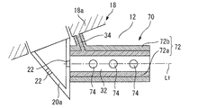
3−1.実施の形態2に対する相違点
図7は、本発明の実施の形態3に係るダクト70の構成を説明するための図である。本実施形態の内燃機関は、以下に説明する点において、実施の形態2の内燃機関と相違している。
3-1. Difference from Second Embodiment FIG. 7 is a diagram for explaining a configuration of a
具体的には、実施の形態2では、噴孔22の出口とダクト60の入口(整流通路32の入口)との間には、隙間Gが形成されている(図6参照)。これに対し、本実施形態では、図7に示すように、そのような隙間Gは設けられておらず、噴孔22を有する先端部20aの外壁とダクト70の入口(整流通路32の入口)とは接している。付け加えると、ダクト70の通路壁部72は、噴孔22の軸線L1に沿って先端部20aの外壁から突出している。
Specifically, in the second embodiment, a gap G is formed between the outlet of the
通路壁部72は、第1層72aと第2層72bとを備える。第1層72aの材質は実施の形態2の第1層62aの材質と同じであり、第2層72bの材質は第2層62bの材質と同じである。ただし、図7に示すように、通路壁部72には、整流通路32と燃焼室12とを連通させるために、任意の数(例えば、3つ)の連通孔74が形成されている。連通孔74は、第1層72aと第2層72bとを貫通している。このような連通孔74を備えるダクト70によれば、ダクト70の周囲の充填ガスは、この連通孔74を利用して、噴孔22から噴射された燃料とともに整流通路32に流入する。
The
3−2.効果
以上説明したように、本実施形態のダクト70の第1層72a及び第2層72bの材質は、実施の形態2の第1層62a及び第2層62bの材質と同じである。このため、本実施形態のダクト70によっても、実施の形態2と同様の効果が得られる。すなわち、整流通路32の壁面(第1層72aの内壁)の温度上昇を抑制する効果とともに、連通孔74を介してダクト70に吸い込まれる充填ガスの加熱が抑制される。
3-2. Effect As described above, the material of the
なお、上述した実施の形態3のダクト70は、連通孔74を利用しているが、この連通孔74とともに隙間Gを有するように配置されたダクトによっても、実施の形態2及び3と同様の効果を奏する。
Although the
4.実施の形態4
次に、図8及び図9を参照して、本発明の実施の形態4について説明する。
4. Embodiment 4
Next, a fourth embodiment of the present invention will be described with reference to FIGS.
4−1.実施の形態2に対する相違点
図8は、本発明の実施の形態4に係る圧縮自着火式内燃機関80の燃焼室82周りの構成を模式的に表した縦断面図である。図9は、図8中のA−A線で通路壁部88を切断して得られる横断面図である。本実施形態の内燃機関80は、以下に説明する点において、実施の形態2の内燃機関と相違している。
4-1. FIG. 8 is a longitudinal sectional view schematically showing a configuration around a
具体的には、内燃機関80は、燃焼室天井部84aを有するシリンダヘッド84を備えている。燃焼室天井部84aには、図6に示す整流通路32と同様の機能を有する整流通路86が形成されている。換言すると、本実施形態では、整流通路86を形成する「通路形成部材」は、シリンダヘッド84(燃焼室天井部84a)と一体化されている。
Specifically, the
図8及び図9に示すように、燃焼室天井部84aは、整流通路86の径方向外側に位置する通路壁部88を備えている。通路壁部88は、第1層88aと第2層88bとを有する。第1層88aは、シリンダヘッド84(燃焼室天井部84a)に繋がる基部である。すなわち、第1層88aは、シリンダヘッド84と一体的に形成されている。付け加えると、第1層88aは、燃焼室天井部84aの基本面84a1から燃焼室12側に突出するように形成されている。
As shown in FIGS. 8 and 9, the
第2層88bは、第1層88aの径方向外側に位置している。図9に示す例では、第2層88bは、燃焼室天井部84aの基本面84a1から突出している第1層88aを覆うように形成されている。また、この例では、第2層88bは、整流通路86の入口側における第1層88aの端面88a1をも覆うように形成されている。
The
本実施形態の通路壁部88の第1層88a及び第2層88bの材質は、一例として、実施の形態2の第1層62a及び第2層62bの材質と同じである。また、本実施形態においても、噴孔22の出口と整流通路86の入口との間には、隙間Gが形成されている。内燃機関80は、このような隙間Gに代え、或いはそれとともに、連通孔74(図7参照)と同様の連通孔を備えていてもよい。
The material of the
4−2.効果
以上説明した通路壁部88を有する内燃機関80によっても、ダクト60を有する実施の形態2の内燃機関と同様の効果を奏する。また、図8に示す例では、第2層88bは、整流通路86の入口側における第1層88aの端面88a1をも覆うように形成されている。これにより、高温の燃焼ガスから当該88a1への入熱に起因して整流通路76の壁面温度が上昇することをも抑制できる。
4-2. Effects The same effects as those of the internal combustion engine of the second embodiment having the
なお、本実施形態のダクト60の第2層88bの材料として、実施の形態1の第2層36bと同じ窒化ケイ素(すなわち、熱容量に関しては上述の関係を満たさない材料の例)が用いられてもよい。そして、この例(すなわち、隙間G(図6参照)や連通孔を介してダクトに吸い込まれる充填空気の加熱の抑制効果までは求めない例)では、第2層88bは、図8に示す例に代え、第1層88aの径方向内側に設けられてもよい。このことは、後述の実施の形態5についても同様である。
In addition, as the material of the
5.実施の形態5
次に、図10を参照して、本発明の実施の形態5について説明する。
5. Embodiment 5
Next, a fifth embodiment of the present invention will be described with reference to FIG.
5−1.実施の形態4に対する相違点
図10は、本発明の実施の形態5に係る圧縮自着火式内燃機関90の燃焼室92周りの構成を模式的に表した縦断面図である。本実施形態の内燃機関90は、以下に説明する点において、実施の形態4の内燃機関80と相違している。
5-1. Difference from Embodiment 4 FIG. 10 is a longitudinal sectional view schematically showing a configuration around a
具体的には、内燃機関90は、燃焼室天井部94aを有するシリンダヘッド94を備えている。燃焼室天井部94aには、図8に示す整流通路86と同様の機能を有する整流通路96を形成する通路形成部材98が締結具(図示省略)によって締結されている。すなわち、本実施形態では、通路形成部材98は、シリンダヘッド94と別体である。通路形成部材98は、第1層100aと第2層100bとを有する通路壁部100を備えている。通路壁部100は、図8に示す通路壁部88と同様に構成されている。付け加えると、第1層100aは、通路壁部100とシリンダヘッド94との締結面を介してシリンダヘッド94と繋がっている。
Specifically, the
5−2.効果
以上説明したように、本実施形態の通路壁部100は、シリンダヘッド94と別体の通路形成部材98に形成されている。このような構成を有する内燃機関90によっても、ダクト60を有する実施の形態2の内燃機関と同様の効果を奏する。
5-2. Effects As described above, the
6.実施の形態6
次に、図11〜図16を参照して、本発明の実施の形態6及びその変形例について説明する。
6. Embodiment 6
Next, a sixth embodiment of the present invention and modifications thereof will be described with reference to FIGS.
6−1.燃焼室周りの構成
図11は、本発明の実施の形態6に係る圧縮自着火式内燃機関110の燃焼室112周りの構成を模式的に表した縦断面図である。以下、実施の形態1の内燃機関10に対する本実施形態の内燃機関110の相違点を中心に説明する。
6-1. Configuration around Combustion Chamber FIG. 11 is a longitudinal sectional view schematically showing a configuration around a
図11に示すように、内燃機関110は、シリンダ114の内部にピストン116を備えている。ピストン116の中央部にはキャビティ118が形成されている。キャビティ118も燃焼室112の一部を構成する。シリンダヘッド120の燃焼室天井部120aの中央には、燃料噴射ノズル20が配置されている。
As shown in FIG. 11, the
ピストン116は、その頂部に整流板122を備えている。整流板122は、ピストン116の頂面に構成されたキャビティ118との間に所定の隙間を置いてピストン116に固定されている。以下、図12及び図13も参照して、整流板122が固定されたピストン116の構成について、さらに詳しく説明する。
The
図12は、図11に示す整流板122が固定されたピストン116をその頂面の側から見下ろした図である。図13は、図11に示す整流板122周りの構成を拡大して示す図である。これらの図に示すように、整流板122は、キャビティ118を構成する面のうち、ピストン116の外周方向に向かって下方に傾斜した円錐面124を覆うように、円錐面で構成された円環形状を有している。整流板122は、円錐面124との隙間が一定となるように構成され、支柱部126を介してピストン116に固定されている。
FIG. 12 is a view in which the
支柱部126は、隣り合う燃料噴霧Fの間の位置において、円環形状の整流板122の内縁端から外縁端に向かって放射状に延びている。このような構成によれば、それぞれの燃料噴霧Fの下方には、整流板122と円錐面124との隙間に、外縁端側(つまりシリンダ114のボア壁面側)の入口128から内縁端側(つまりシリンダ114のボア中心側)の出口130へと連通する整流通路132が形成される。入口128及び出口130は、燃焼室112に露出している。
The
6−1−1.2層構造を有する整流板(通路壁部)
整流板122は、整流通路132に対して燃焼室天井部120aの側に位置している。本実施形態の内燃機関110では、この整流板122が本発明の他の態様に係る「通路壁部」の一例に相当する。図13に示すように、整流板(通路壁部)122は、第1層122aと第2層122bとからなる2層構造である。
6-1.1.2 Rectifier plate having a layer structure (passage wall)
The
第1層122aは、支柱部126を介して、ピストン116に繋がる基部(基層)に相当する。すなわち、整流板(通路壁部)122の第1層122aが支柱部126によって支持されている。
The
第2層122bは、第1層122aに対して燃焼室天井部120aの側に位置している。より詳細には、第2層122bは、一例として、第1層122aの全体を覆うように形成されている。また、第1層122a及び第2層122bの材質は、一例として、実施の形態1の第1層36a及び第2層36bの材質と同じである。すなわち、第1層122aの靱性は第2層122bの靱性よりも高く、かつ、第2層122bの熱伝導率は第1層122aの熱伝導率よりも低い。
The
6−2.効果
6−2−1.整流板(通路壁部)の利用による効果
まず、図14及び図15を参照して、整流板122の作用及び効果について説明する。図14は、整流板を備えていない比較例のピストン200を備える圧縮自着火式内燃機関の燃焼室内の空気の流れを説明するための模式図である。また、図15は、図11に示す整流板122が固定された実施の形態6のピストン116を備える圧縮自着火式内燃機関110の燃焼室112内の空気の流れを説明するための模式図である。
6-2. Effect 6-2-1. Effect of Use of Rectifier Plate (Path Wall) First, the operation and effect of the
まず、比較例として、整流板122を備えていないピストン200を備える内燃機関の燃焼室内の空気の流れを説明する。図14に示すように、整流板122を備えていない内燃機関では、筒内ガス(より詳細には、燃焼室内の新気)が高温の既燃ガスと混ざりながら燃料噴霧Fの根元部分に取り込まれる。このような構成によれば、着火後の高温の既燃ガスが燃料噴霧Fに混ざることとなるため、噴射された燃料が逸早く自着火してしまうおそれがある。その結果、過濃燃料が燃焼することによるスモークの発生、又は後燃え期間が長期化することによる熱効率の低下が問題となる。
First, as a comparative example, the flow of air in the combustion chamber of an internal combustion engine including the piston 200 without the straightening
これに対し、本実施形態の内燃機関110では、上記の問題を解決するために、ピストン116に整流板122を設けることとしている。図15に示すように、ピストン116の円錐面124と整流板122との間の隙間には、整流通路132が形成されている。燃料噴射ノズル20から噴射された燃料噴霧Fは、整流板122の上面(燃焼室天井部120a側の表面)に沿ってキャビティ118内へと拡散する。この際、燃焼室112内の新気は、入口128から整流通路132の内部へと導入される。整流通路132は、整流板122によって燃料噴霧Fと隔絶されている。このため、入口128から整流通路132の内部へと導入された新気は、高温の既燃ガスと混ざることが抑制されながら出口130から導出される。これにより、低温を維持した新気が燃料噴霧Fの根元部分へと取り込まれるため、噴射された燃料が着火するまでの時間が確保される。これにより、過濃燃料が燃焼することを防ぐことができるので、スモークの発生、及び後燃え期間が長期化することによる熱効率の低下を抑制することが可能となる。
On the other hand, in the
また、本実施形態の内燃機関110では、燃料噴霧Fの下側に整流通路132が設けられているため、出口130から導出された低温の新気を燃料噴霧Fの根元部分へと効率よく取り込ませることが可能となる。
Further, in the
6−2−2.整流板(通路壁部)の設置に関する課題
整流板122のような整流板は、燃焼室に露出している。つまり、整流板122は、実施の形態1のダクト30の例と同様に、高温の燃焼ガスに晒されることによって高温になり易い環境下に配置されている。燃焼ガスからの受熱によって整流通路の壁面(整流板のピストン側の壁面)自体が高温になると、整流板を通過する新気が整流板からの受熱によって温められてしまう。その結果、着火遅れが短縮する(自着火時期を遅らせる効果が減少する)ため、燃料噴霧と充填空気との混合が不足したまま燃焼が開始される。これにより、スモークの発生を適切に抑制することが難しくなることが懸念される。
6-2-2. Issues Related to Installation of Rectifier Plate (Path Wall) A rectifier plate such as the
また、ダクトの例と同様に、整流板(通路壁部)に関しても、温度上昇の抑制に関する対策は、荷重又は負荷が整流板に繰り返しかかったとしても、より確実に整流板の形状を長期間にわたって維持できることを保証しつつなされることが要求される。 In addition, as in the case of the duct, for the flow straightening plate (passage wall), measures to suppress the temperature rise are to ensure that the shape of the current straightening plate can be more reliably maintained for a long time even if a load or load is repeatedly applied to the current straightening plate. It must be done while ensuring that it can be maintained over time.
1−2−3.2層構造を有する整流板(通路壁部)の採用
上記の課題に鑑み、本実施形態の整流板(通路壁部)122では、第1層122aは、支柱部126を介してピストン116に繋がる基部として構成されている。そして、この第1層122aの靱性が第2層122bの靱性よりも高くなるように両者の材料が選定されている。これにより、上述の荷重又は負荷が整流板122に繰り返しかかったとしても、より確実に整流板122の形状を長期間にわたって保持できる。
1-2-3.2 Adoption of straightening plate (passage wall portion) having a two-layer structure In view of the above problem, in straightening plate (passage wall portion) 122 of the present embodiment,
そして、整流板122の第2層122bの熱伝導率が第1層122aの熱伝導率よりも低くなるように両者の材料が選定されている。これにより、整流板122の周囲の高温の燃焼ガスから整流板122の燃焼室天井部120a側の壁(第2層122bの外壁)に伝えられた熱が、整流板122のピストン116側の壁(すなわち、整流通路132の壁面)に伝わることを抑制できる。このため、整流板122のピストン116側に位置する整流通路132を筒内ガス(新気)が通過する際に、新気の温度上昇を抑制することができる。その結果、自着火時期を遅らせる効果の減少を抑制できる。
The two materials are selected so that the thermal conductivity of the
以上のように、本実施形態の内燃機関110によれば、整流板122(通路壁部)の形状維持の信頼性の確保と、整流通路132の壁面温度の上昇抑制とを好適に両立させることができる。
As described above, according to the
また、第2層122bの材料として、実施の形態2の62bと同様に、第1層122aと比べて単位時間当たりの熱容量の小さなものが選定されてもよい。その結果、第2層122bの温度が常に高くなることを抑制できるので、整流通路132の壁面の温度上昇をより効果的に抑制できるようになる。
Further, as the material of the
6−3.実施の形態6に関する変形例
6−3−1.通路壁部の2層構造の他の例
図16は、整流板(通路壁部)の第1層及び第2層の他の構成例を説明するための図である。図16に示す例では、整流板140(通路壁部)は、基部である第1層140aと、第1層140aに対してピストン116の側に位置する第2層140bとを有する。このように、通路壁部の2層構造の構成が変更されてもよい。
6-3. Modification 6-3-1 relating to Embodiment 6 Another Example of Two-Layer Structure of Passage Wall Portion FIG. 16 is a view for explaining another configuration example of the first and second layers of the current plate (passage wall portion). In the example illustrated in FIG. 16, the current plate 140 (passage wall portion) includes a
6−3−2.整流通路の他の構成例
上述した実施の形態6における整流通路132は、整流板122とキャビティ118との間に形成されている。しかしながら、本発明の他の態様に係るピストンの頂部に形成される「整流通路」は、上記の構成に代え、ピストンのキャビティを構成する壁部に直接的に形成された貫通孔であってもよい。この例では、2重底形状を有するキャビティの壁部のうちの燃焼室天井部側の部位が本発明の他の態様に係る「通路壁部」の一例に相当する。
6-3-2. Another Configuration Example of Rectifying Path The rectifying
7.他の実施の形態
7−1.第2層の材料の他の選定例
靱性と熱伝導率に加え、単位時間当たりの熱容量に関しても上述の関係を満たす「第2層」の他の例は、既述したジルコニア(ZrO2)に代え、次のようなものであってもよい。すなわち、「第1層」の材料としてアルミニウム合金を使用する場合には、第1層の表面に対して陽極酸化処理を施すことにより形成されるアルマイト膜であってもよい。アルマイト膜によれば、陽極酸化処理の過程で形成される細孔を有する多孔質構造が得られるので、第2層は、第1層よりも熱伝導率及び単位体積当たりの熱容量の小さい遮熱膜として機能する。
7. Other Embodiment 7-1. Another example of selecting the material of the second layer In addition to the toughness and the thermal conductivity, another example of the “second layer” that satisfies the above-mentioned relationship with respect to the heat capacity per unit time is zirconia (ZrO 2 ) described above. Alternatively, the following may be used. That is, when an aluminum alloy is used as the material of the “first layer”, an alumite film formed by performing anodizing treatment on the surface of the first layer may be used. According to the alumite film, a porous structure having pores formed in the process of anodic oxidation treatment can be obtained. Therefore, the second layer has a smaller thermal conductivity and a smaller heat capacity per unit volume than the first layer. Functions as a membrane.
また、「第2層」の他の例は、既述したジルコニア(ZrO2)に代え、ジルコン(ZrSiO4)、シリカ(SiO2)、窒化珪素(Si3N4)、イットリア(Y2O3)、酸化チタン(TiO2)などの他のセラミックスの溶射により得られる膜であってもよい。これらの溶射膜は、溶射の過程で形成される内部気泡を有するので、アルマイト膜と同様に、第1層の材料として用いられるアルミニウム又は鉄などの金属と比べて、単位体積当たりの熱容量の小さい遮熱膜として機能する。 Another example of the “second layer” is zircon (ZrSiO 4 ), silica (SiO 2 ), silicon nitride (Si 3 N 4 ), yttria (Y 2 O) instead of zirconia (ZrO 2 ) described above. 3 ) or a film obtained by spraying other ceramics such as titanium oxide (TiO 2 ). Since these sprayed films have internal bubbles formed in the process of spraying, similar to the alumite film, the heat capacity per unit volume is smaller than that of a metal such as aluminum or iron used as the material of the first layer. Functions as a heat shield film.
さらに、「第2層」の他の例は、第2層の全体として靱性、熱伝導率及び単位時間当たりの熱容量に関する上述の関係を満たす限り、次のような構造を有する断熱膜(遮熱膜)であってもよい。すなわち、この遮熱膜は、第1の断熱材及び第2の断熱材を含む。第1の断熱材は、母材(第1層)よりも低い熱伝導率及び母材よりも低い単位体積あたりの熱容量を有する。第2の断熱材は、母材以下の熱伝導率を有する。また、第1の断熱材は、第2の断熱材よりも低い熱伝導率及び第2の断熱材よりも低い単位体積あたりの熱容量を有する。そして、第1の断熱材は、中空のセラミックビーズ、中空のガラスビーズ、微細多孔構造の断熱材、シリカエアロゲル、またはこれら複数の組み合わせであり、第2の断熱材は、ジルコニア、シリコン、チタン、ジルコニウム、セラミック、セラミック繊維、またはこれら複数の組み合わせである。なお、このような構成を有する遮熱膜の詳細については、特許第5629463号に記載されている。 Further, other examples of the “second layer” include a heat insulating film (a heat shield) having the following structure as long as the above-mentioned relationship regarding the toughness, thermal conductivity, and heat capacity per unit time as a whole of the second layer is satisfied. Film). That is, the heat shield film includes the first heat insulator and the second heat insulator. The first heat insulating material has a lower thermal conductivity than the base material (first layer) and a lower heat capacity per unit volume than the base material. The second heat insulating material has a thermal conductivity lower than that of the base material. Further, the first heat insulating material has a lower thermal conductivity than the second heat insulating material and a lower heat capacity per unit volume than the second heat insulating material. The first heat insulating material is a hollow ceramic bead, a hollow glass bead, a heat insulating material having a microporous structure, a silica airgel, or a combination thereof. The second heat insulating material is zirconia, silicon, titanium, Zirconium, ceramic, ceramic fiber, or a combination thereof. The details of the heat shielding film having such a configuration are described in Japanese Patent No. 5629463.
7−2.圧縮自着火式内燃機関の他の例
上述した実施の形態1〜6においては、圧縮自着火式内燃機関の例として、ディーゼルエンジンが用いられている。しかしながら、本発明の対象となる圧縮自着火式内燃機関は、ディーゼルエンジンに代え、例えば、ガソリンを燃料として用いる予混合圧縮自着火式内燃機関であってもよい。
7-2. Another Example of Compression Ignition Internal Combustion Engine In the first to sixth embodiments described above, a diesel engine is used as an example of the compression self ignition internal combustion engine. However, the compression ignition internal combustion engine to which the present invention is applied may be, for example, a homogeneous charge compression ignition internal combustion engine using gasoline as fuel instead of the diesel engine.
7−3.2層よりも多い多層構造の例
本発明に係る整流通路の通路壁部は、本発明に係る「第1層」及び「第2層」を含むものであれば、上述した実施の形態1〜6のような2層構造に限られず、3層以上の多層構造を有してもよい。すなわち、例えば、通路壁部は、「第1層」と「第2層」との間に中空層を有する3層構造を有してもよい。また、通路壁部は、例えば、通路壁部の靱性を上げるために、或いは伝熱量を下げるために、「第1層」と「第2層」との間、「第1層」における「第2層」と反対側、又は、「第2層」における「第1層」と反対側に、異なる材質の第3層を有してもよい。このような第3層の例には、第1層と第2層との接合を強固にしたり又は第1層に対する第2層のコーティングを強固にしたりするための部材を有する層が含まれる。
7-3.2 Example of Multilayer Structure with More Than Two Layers If the passage wall of the rectifying passage according to the present invention includes the “first layer” and the “second layer” according to the present invention, the above-described embodiment is applicable. The present invention is not limited to the two-layer structure as in the first to sixth embodiments, and may have a multilayer structure of three or more layers. That is, for example, the passage wall may have a three-layer structure having a hollow layer between the “first layer” and the “second layer”. In addition, for example, in order to increase the toughness of the passage wall portion or to reduce the heat transfer amount, the passage wall portion may be located between the “first layer” and the “second layer” and the “first layer”. A third layer of a different material may be provided on the side opposite to the “second layer” or on the side opposite to the “first layer” in the “second layer”. Examples of such a third layer include a layer having a member for strengthening the bond between the first layer and the second layer or for strengthening the coating of the second layer on the first layer.
7−4.通路壁部の他の例
本発明の対象となり、かつ、シリンダヘッドに繋がる第1層を有する「通路壁部」には、上述した実施の形態1〜5とは異なり、隙間G(図2参照)及び連通孔74(図7参照)の何れも有しない通路壁部も含まれる。すなわち、このような通路壁部を対象として、整流通路の壁面温度の上昇を抑制するために、「第1層」及び「第2層」を含むように通路壁部が構成されてもよい。
7-4. Another Example of Passage Wall Portion The “passage wall portion” which is the object of the present invention and has the first layer connected to the cylinder head is different from Embodiments 1 to 5 described above in that a gap G (see FIG. 2) ) And the communication wall 74 (see FIG. 7). That is, for such a passage wall, the passage wall may be configured to include the “first layer” and the “second layer” in order to suppress a rise in the wall surface temperature of the rectifying passage.
以上説明した各実施の形態に記載の例及び他の各変形例は、明示した組み合わせ以外にも可能な範囲内で適宜組み合わせてもよいし、また、本発明の趣旨を逸脱しない範囲で種々変形してもよい。 The examples and other modifications described in the embodiments described above may be appropriately combined within a possible range other than the explicit combination, and various modifications may be made without departing from the spirit of the present invention. May be.
10、80、90、110 圧縮自着火式内燃機関
12、82、92、112 燃焼室
14、84、94、120 シリンダブロック
16、116 ピストン
18 シリンダヘッド
18a、84a、94a、120a 燃焼室天井部
20 燃料噴射ノズル
20a 燃料噴射ノズルの先端部
22 燃料噴射ノズルの噴孔
30、40、50、60、70 ダクト
32、76、86、96 整流通路
34、54、126 支柱部
36、42、52、62、72、88、100 通路壁部
36a、42a、52a、62a、72a、88a、100a、122a、140a 第1層
36b、42b、52b、62b、72b、88b、100b、122b、140b 第2層
74 連通孔
98 通路形成部材
118 ピストンのキャビティ
122、140 整流板
124 キャビティの円錐面
132 整流通路
10, 80, 90, 110 Compression-ignition
Claims (9)
前記噴孔から噴射された燃料が通過する整流通路を形成する通路形成部材と、
を備え、
前記通路形成部材は、前記整流通路の径方向外側に位置する通路壁部を含み、
前記通路壁部は、シリンダヘッドに繋がる基部である第1層と、前記第1層の径方向外側又は内側に位置する第2層とを含み、
前記第1層の靱性は、前記第2層の靱性よりも高く、
前記第2層の熱伝導率は、前記第1層の熱伝導率よりも低い
ことを特徴とする圧縮自着火式内燃機関。 A fuel injection nozzle having an injection hole provided at a tip end exposed to the combustion chamber,
A passage forming member that forms a rectifying passage through which the fuel injected from the injection hole passes;
With
The passage forming member includes a passage wall located radially outside the rectifying passage,
The passage wall includes a first layer that is a base connected to the cylinder head, and a second layer that is located radially outside or inside the first layer.
The toughness of the first layer is higher than the toughness of the second layer,
The thermal conductivity of the second layer is lower than the thermal conductivity of the first layer. A compression ignition internal combustion engine.
ことを特徴とする請求項1に記載の圧縮自着火式内燃機関。 2. The compression ignition internal combustion engine according to claim 1, wherein the second layer is located radially outside the first layer. 3.
前記第2層の単位体積当たりの熱容量は、前記第1層の単位体積当たりの熱容量よりも小さい
ことを特徴とする請求項1又は2に記載の圧縮自着火式内燃機関。 A gap is formed between the outlet of the injection hole and the inlet of the straightening passage,
3. The compression ignition internal combustion engine according to claim 1, wherein a heat capacity per unit volume of the second layer is smaller than a heat capacity per unit volume of the first layer. 4.
前記第2層の単位体積当たりの熱容量は、前記第1層の単位体積当たりの熱容量よりも小さい
ことを特徴とする請求項1〜3の何れか1つに記載の圧縮自着火式内燃機関。 In the passage wall portion, a communication hole for communicating the rectifying passage and the combustion chamber is formed,
The compression ignition internal combustion engine according to any one of claims 1 to 3, wherein a heat capacity per unit volume of the second layer is smaller than a heat capacity per unit volume of the first layer.
前記通路壁部は、前記第1層と前記第2層からなり、かつ、筒状に形成されている
ことを特徴とする請求項1〜4の何れか1つに記載の圧縮自着火式内燃機関。 The passage forming member includes the passage wall, and a column connecting the first layer and the cylinder head.
The compression self-ignition type internal combustion engine according to any one of claims 1 to 4, wherein the passage wall portion includes the first layer and the second layer, and is formed in a cylindrical shape. organ.
ことを特徴とする請求項1〜4の何れか1つに記載の圧縮自着火式内燃機関。 The compression self-ignition internal combustion engine according to any one of claims 1 to 4, wherein the passage forming member is formed integrally with the cylinder head.
ことを特徴とする請求項1〜4の何れか1つに記載の圧縮自着火式内燃機関。 The compression ignition internal combustion engine according to any one of claims 1 to 4, wherein the passage forming member is fastened to a ceiling of a combustion chamber of the cylinder head.
シリンダの内部に配置され、筒内ガスが通過する整流通路が形成された頂部を有するピストンと、
を備え、
前記整流通路は、前記シリンダのボア壁面側において前記燃焼室に露出する入口からボア中心側において前記燃焼室に露出する出口に向かって連通し、
前記ピストンは、前記整流通路に対して前記燃焼室天井部の側に位置する通路壁部を含み、
前記通路壁部は、前記ピストンに繋がる基部である第1層と、前記第1層に対して前記ピストンの側又は前記燃焼室天井部の側に位置する第2層とを含み、
前記第1層の靱性は、前記第2層の靱性よりも高く、
前記第2層の熱伝導率は、前記第1層の熱伝導率よりも低い
ことを特徴とする圧縮自着火式内燃機関。 A fuel injection nozzle having an injection hole provided at a tip end exposed to the combustion chamber at the center of the combustion chamber ceiling,
A piston disposed inside the cylinder and having a top formed with a rectifying passage through which the in-cylinder gas passes;
With
The straightening passage communicates from an inlet exposed to the combustion chamber on a bore wall surface side of the cylinder to an outlet exposed to the combustion chamber on a bore center side,
The piston includes a passage wall located on a side of the combustion chamber ceiling with respect to the straightening passage,
The passage wall portion includes a first layer that is a base connected to the piston, and a second layer that is located on the side of the piston or the ceiling of the combustion chamber with respect to the first layer,
The toughness of the first layer is higher than the toughness of the second layer,
The thermal conductivity of the second layer is lower than the thermal conductivity of the first layer. A compression ignition internal combustion engine.
ことを特徴とする請求項8に記載の圧縮自着火式内燃機関。 The compression ignition internal combustion engine according to claim 8, wherein the heat capacity per unit volume of the second layer is smaller than the heat capacity per unit volume of the first layer.
Priority Applications (7)
| Application Number | Priority Date | Filing Date | Title |
|---|---|---|---|
| JP2018129991A JP2020007977A (en) | 2018-07-09 | 2018-07-09 | Compression self-ignition internal combustion engine |
| US16/430,602 US11300046B2 (en) | 2018-07-09 | 2019-06-04 | Compression-ignition internal combustion engine |
| EP19179257.1A EP3594487B1 (en) | 2018-07-09 | 2019-06-10 | Compression-ignition internal combustion engine |
| BR102019011837A BR102019011837A2 (en) | 2018-07-09 | 2019-06-11 | compression ignition internal combustion engine |
| RU2019119223A RU2719518C1 (en) | 2018-07-09 | 2019-06-20 | Internal combustion engine with compression ignition (embodiments) |
| CN201910553860.0A CN110700981B (en) | 2018-07-09 | 2019-06-25 | Compression self-ignition internal combustion engine |
| KR1020190082089A KR20200006009A (en) | 2018-07-09 | 2019-07-08 | Compression-ignition internal combustion engine |
Applications Claiming Priority (1)
| Application Number | Priority Date | Filing Date | Title |
|---|---|---|---|
| JP2018129991A JP2020007977A (en) | 2018-07-09 | 2018-07-09 | Compression self-ignition internal combustion engine |
Publications (1)
| Publication Number | Publication Date |
|---|---|
| JP2020007977A true JP2020007977A (en) | 2020-01-16 |
Family
ID=67070536
Family Applications (1)
| Application Number | Title | Priority Date | Filing Date |
|---|---|---|---|
| JP2018129991A Pending JP2020007977A (en) | 2018-07-09 | 2018-07-09 | Compression self-ignition internal combustion engine |
Country Status (7)
| Country | Link |
|---|---|
| US (1) | US11300046B2 (en) |
| EP (1) | EP3594487B1 (en) |
| JP (1) | JP2020007977A (en) |
| KR (1) | KR20200006009A (en) |
| CN (1) | CN110700981B (en) |
| BR (1) | BR102019011837A2 (en) |
| RU (1) | RU2719518C1 (en) |
Cited By (1)
| Publication number | Priority date | Publication date | Assignee | Title |
|---|---|---|---|---|
| EP3961009A1 (en) | 2020-09-01 | 2022-03-02 | Mazda Motor Corporation | Engine |
Families Citing this family (5)
| Publication number | Priority date | Publication date | Assignee | Title |
|---|---|---|---|---|
| JP7069776B2 (en) * | 2018-02-07 | 2022-05-18 | トヨタ自動車株式会社 | Internal combustion engine |
| JP6888570B2 (en) * | 2018-03-07 | 2021-06-16 | トヨタ自動車株式会社 | Internal combustion engine |
| US10900450B1 (en) * | 2019-08-05 | 2021-01-26 | Caterpillar Inc. | Fuel system, fuel injector nozzle assembly, and engine head assembly structured for ducted fuel injection |
| JP7347105B2 (en) | 2019-10-16 | 2023-09-20 | 株式会社デンソー | Stator manufacturing equipment and stator manufacturing method |
| US11852113B2 (en) | 2022-02-02 | 2023-12-26 | Caterpillar Inc. | Fuel injector having spray ducts sized for optimized soot reduction |
Citations (8)
| Publication number | Priority date | Publication date | Assignee | Title |
|---|---|---|---|---|
| JPH055415A (en) * | 1991-06-03 | 1993-01-14 | Shinnenshiyou Syst Kenkyusho:Kk | Combustion chamber for direct injection type diesel engine |
| US20010012196A1 (en) * | 1999-10-07 | 2001-08-09 | International Business Machines Corp. | Laptop computer with ergonomically enhanced interface features |
| JP2004308449A (en) * | 2003-04-02 | 2004-11-04 | Komatsu Ltd | Diesel engine |
| JP2006307825A (en) * | 2005-03-29 | 2006-11-09 | Nissan Motor Co Ltd | Cylinder direct injection type internal combustion engine and fuel injection valve |
| JP2012047134A (en) * | 2010-08-27 | 2012-03-08 | Toyota Central R&D Labs Inc | Internal combustion engine |
| JP2017155639A (en) * | 2016-03-01 | 2017-09-07 | トヨタ自動車株式会社 | Combustion chamber structure of internal combustion engine |
| US20170350308A1 (en) * | 2016-06-01 | 2017-12-07 | Ford Global Technologies, Llc | Controlled air entrainment passage for diesel engines |
| WO2018101991A1 (en) * | 2016-11-29 | 2018-06-07 | National Technology & Engineering Solution Of Sandia, Llc (Ntess) | Ducted fuel injection |
Family Cites Families (24)
| Publication number | Priority date | Publication date | Assignee | Title |
|---|---|---|---|---|
| JPS5321761A (en) | 1976-08-13 | 1978-02-28 | Sansha Electric Mfg Co Ltd | Ac load controlling circuit |
| JPS5629463A (en) | 1979-08-15 | 1981-03-24 | Matsushita Electric Works Ltd | Ac zerovolt switching circuit |
| HUT56922A (en) * | 1990-01-18 | 1991-10-28 | Laszlo Wilheim | Piston provided with eddy-making unit for diesel-engines |
| RU2088794C1 (en) * | 1994-04-18 | 1997-08-27 | Александр Арсентьевич Котешов | Nozzle spray tip |
| JPH09329071A (en) * | 1996-06-12 | 1997-12-22 | Shin A C Ii:Kk | Fuel injection nozzle of diesel engine |
| DE10210976A1 (en) * | 2002-03-13 | 2003-09-25 | Bosch Gmbh Robert | Fuel injection valve for internal combustion engine has injection jets converging from at least one outer and one inner injection channel |
| US6929852B2 (en) * | 2002-08-08 | 2005-08-16 | Siemens Westinghouse Power Corporation | Protective overlayer for ceramics |
| DE10329524A1 (en) | 2003-06-30 | 2005-01-27 | Daimlerchrysler Ag | Auto-ignition internal combustion engine |
| CN100462534C (en) * | 2004-10-01 | 2009-02-18 | 五十铃自动车株式会社 | Diesel engine |
| JP4342481B2 (en) * | 2005-06-28 | 2009-10-14 | トヨタ自動車株式会社 | In-cylinder injection spark ignition internal combustion engine |
| WO2009020206A1 (en) | 2007-08-09 | 2009-02-12 | Kabushiki Kaisha Toyota Chuo Kenkyusho | Internal combustion engine |
| JP2009127534A (en) * | 2007-11-22 | 2009-06-11 | Toyota Motor Corp | Fuel injection device |
| JP2011236867A (en) * | 2010-05-13 | 2011-11-24 | Hino Motors Ltd | Fuel spray nozzle |
| JP2013092103A (en) | 2011-10-26 | 2013-05-16 | Isuzu Motors Ltd | Internal combustion engine |
| US10626290B2 (en) | 2013-12-16 | 2020-04-21 | Ppg Industries Ohio, Inc. | Method of extending pot life of coating compositions |
| US9909549B2 (en) * | 2014-10-01 | 2018-03-06 | National Technology & Engineering Solutions Of Sandia, Llc | Ducted fuel injection |
| US20160298584A1 (en) * | 2015-04-13 | 2016-10-13 | Caterpillar Inc. | Ducted Combustion Systems Utilizing Outside Air Injection |
| US9587606B2 (en) | 2015-04-13 | 2017-03-07 | Caterpillar Inc. | Ducted combustion systems utilizing tubular ducts |
| JP6233391B2 (en) * | 2015-11-26 | 2017-11-22 | トヨタ自動車株式会社 | Internal combustion engine |
| GB2553838B (en) | 2016-09-16 | 2020-01-29 | Perkins Engines Co Ltd | Fuel injector and piston bowl |
| US10801395B1 (en) * | 2016-11-29 | 2020-10-13 | National Technology & Engineering Solutions Of Sandia, Llc | Ducted fuel injection |
| US10012196B1 (en) | 2017-08-30 | 2018-07-03 | Caterpillar Inc. | Duct structure for fuel injector assembly |
| US10711752B2 (en) * | 2017-08-31 | 2020-07-14 | Caterpillar Inc. | Fuel injector assembly having duct structure |
| JP6881285B2 (en) | 2017-12-27 | 2021-06-02 | トヨタ自動車株式会社 | Internal combustion engine |
-
2018
- 2018-07-09 JP JP2018129991A patent/JP2020007977A/en active Pending
-
2019
- 2019-06-04 US US16/430,602 patent/US11300046B2/en active Active
- 2019-06-10 EP EP19179257.1A patent/EP3594487B1/en active Active
- 2019-06-11 BR BR102019011837A patent/BR102019011837A2/en not_active IP Right Cessation
- 2019-06-20 RU RU2019119223A patent/RU2719518C1/en active
- 2019-06-25 CN CN201910553860.0A patent/CN110700981B/en active Active
- 2019-07-08 KR KR1020190082089A patent/KR20200006009A/en active IP Right Grant
Patent Citations (8)
| Publication number | Priority date | Publication date | Assignee | Title |
|---|---|---|---|---|
| JPH055415A (en) * | 1991-06-03 | 1993-01-14 | Shinnenshiyou Syst Kenkyusho:Kk | Combustion chamber for direct injection type diesel engine |
| US20010012196A1 (en) * | 1999-10-07 | 2001-08-09 | International Business Machines Corp. | Laptop computer with ergonomically enhanced interface features |
| JP2004308449A (en) * | 2003-04-02 | 2004-11-04 | Komatsu Ltd | Diesel engine |
| JP2006307825A (en) * | 2005-03-29 | 2006-11-09 | Nissan Motor Co Ltd | Cylinder direct injection type internal combustion engine and fuel injection valve |
| JP2012047134A (en) * | 2010-08-27 | 2012-03-08 | Toyota Central R&D Labs Inc | Internal combustion engine |
| JP2017155639A (en) * | 2016-03-01 | 2017-09-07 | トヨタ自動車株式会社 | Combustion chamber structure of internal combustion engine |
| US20170350308A1 (en) * | 2016-06-01 | 2017-12-07 | Ford Global Technologies, Llc | Controlled air entrainment passage for diesel engines |
| WO2018101991A1 (en) * | 2016-11-29 | 2018-06-07 | National Technology & Engineering Solution Of Sandia, Llc (Ntess) | Ducted fuel injection |
Cited By (1)
| Publication number | Priority date | Publication date | Assignee | Title |
|---|---|---|---|---|
| EP3961009A1 (en) | 2020-09-01 | 2022-03-02 | Mazda Motor Corporation | Engine |
Also Published As
| Publication number | Publication date |
|---|---|
| US20200011236A1 (en) | 2020-01-09 |
| CN110700981B (en) | 2022-06-21 |
| US11300046B2 (en) | 2022-04-12 |
| BR102019011837A2 (en) | 2020-02-04 |
| EP3594487A2 (en) | 2020-01-15 |
| EP3594487B1 (en) | 2023-11-15 |
| KR20200006009A (en) | 2020-01-17 |
| CN110700981A (en) | 2020-01-17 |
| RU2719518C1 (en) | 2020-04-21 |
| EP3594487A3 (en) | 2020-04-15 |
Similar Documents
| Publication | Publication Date | Title |
|---|---|---|
| JP2020007977A (en) | Compression self-ignition internal combustion engine | |
| US20160273484A1 (en) | Internal combustion engine | |
| JP6010944B2 (en) | Compression self-ignition engine | |
| JP2013053572A (en) | Direct-injection engine combustion chamber structure | |
| JPH11193721A (en) | Direct injection type spark-ignition engine | |
| WO2018185847A1 (en) | Piston | |
| JPH03115722A (en) | Auxiliary chamber type alcohol engine | |
| JP6311654B2 (en) | Engine piston structure | |
| JP2906418B2 (en) | Secondary combustion chamber structure | |
| JP2016132992A (en) | Compression ignition type internal combustion engine | |
| JP2013092103A (en) | Internal combustion engine | |
| JP6920826B2 (en) | Internal combustion engine | |
| JP6526524B2 (en) | Internal combustion engine piston | |
| JP2017040216A (en) | Engine combustion chamber structure | |
| JPH0868330A (en) | Structure of piston having auxiliary chamber | |
| JP6795985B2 (en) | Sub-chamber gas engine | |
| JPH0777105A (en) | Structure of piston provided with auxiliary chamber | |
| JPH0450427A (en) | Auxiliary combustion chamber type heat insulated engine | |
| JPH06159060A (en) | Auxiliary combustion chamber type engine | |
| JP2019157796A (en) | Ignition device and engine with the same | |
| JPS63215819A (en) | Combustion chamber of diesel engine | |
| JPH02112614A (en) | Heat insulating structure for subcombustion chamber | |
| JPH0245612A (en) | Heat insulation engine | |
| JPH03222815A (en) | Piston for internal combustion engine | |
| JPH0821246A (en) | Structure of piston having combustion chamber |
Legal Events
| Date | Code | Title | Description |
|---|---|---|---|
| A521 | Request for written amendment filed |
Free format text: JAPANESE INTERMEDIATE CODE: A523 Effective date: 20180803 |
|
| A621 | Written request for application examination |
Free format text: JAPANESE INTERMEDIATE CODE: A621 Effective date: 20201022 |
|
| A977 | Report on retrieval |
Free format text: JAPANESE INTERMEDIATE CODE: A971007 Effective date: 20210916 |
|
| A131 | Notification of reasons for refusal |
Free format text: JAPANESE INTERMEDIATE CODE: A131 Effective date: 20210921 |
|
| A521 | Request for written amendment filed |
Free format text: JAPANESE INTERMEDIATE CODE: A523 Effective date: 20211110 |
|
| A02 | Decision of refusal |
Free format text: JAPANESE INTERMEDIATE CODE: A02 Effective date: 20211207 |