JP2020007943A - Valve opening and closing timing control device - Google Patents
Valve opening and closing timing control device Download PDFInfo
- Publication number
- JP2020007943A JP2020007943A JP2018128504A JP2018128504A JP2020007943A JP 2020007943 A JP2020007943 A JP 2020007943A JP 2018128504 A JP2018128504 A JP 2018128504A JP 2018128504 A JP2018128504 A JP 2018128504A JP 2020007943 A JP2020007943 A JP 2020007943A
- Authority
- JP
- Japan
- Prior art keywords
- valve
- protrusion
- closing
- rotation axis
- check valve
- Prior art date
- Legal status (The legal status is an assumption and is not a legal conclusion. Google has not performed a legal analysis and makes no representation as to the accuracy of the status listed.)
- Pending
Links
Images


Classifications
-
- F—MECHANICAL ENGINEERING; LIGHTING; HEATING; WEAPONS; BLASTING
- F01—MACHINES OR ENGINES IN GENERAL; ENGINE PLANTS IN GENERAL; STEAM ENGINES
- F01L—CYCLICALLY OPERATING VALVES FOR MACHINES OR ENGINES
- F01L1/00—Valve-gear or valve arrangements, e.g. lift-valve gear
- F01L1/34—Valve-gear or valve arrangements, e.g. lift-valve gear characterised by the provision of means for changing the timing of the valves without changing the duration of opening and without affecting the magnitude of the valve lift
- F01L1/344—Valve-gear or valve arrangements, e.g. lift-valve gear characterised by the provision of means for changing the timing of the valves without changing the duration of opening and without affecting the magnitude of the valve lift changing the angular relationship between crankshaft and camshaft, e.g. using helicoidal gear
- F01L1/3442—Valve-gear or valve arrangements, e.g. lift-valve gear characterised by the provision of means for changing the timing of the valves without changing the duration of opening and without affecting the magnitude of the valve lift changing the angular relationship between crankshaft and camshaft, e.g. using helicoidal gear using hydraulic chambers with variable volume to transmit the rotating force
-
- F—MECHANICAL ENGINEERING; LIGHTING; HEATING; WEAPONS; BLASTING
- F01—MACHINES OR ENGINES IN GENERAL; ENGINE PLANTS IN GENERAL; STEAM ENGINES
- F01L—CYCLICALLY OPERATING VALVES FOR MACHINES OR ENGINES
- F01L1/00—Valve-gear or valve arrangements, e.g. lift-valve gear
- F01L1/34—Valve-gear or valve arrangements, e.g. lift-valve gear characterised by the provision of means for changing the timing of the valves without changing the duration of opening and without affecting the magnitude of the valve lift
- F01L1/344—Valve-gear or valve arrangements, e.g. lift-valve gear characterised by the provision of means for changing the timing of the valves without changing the duration of opening and without affecting the magnitude of the valve lift changing the angular relationship between crankshaft and camshaft, e.g. using helicoidal gear
- F01L1/348—Valve-gear or valve arrangements, e.g. lift-valve gear characterised by the provision of means for changing the timing of the valves without changing the duration of opening and without affecting the magnitude of the valve lift changing the angular relationship between crankshaft and camshaft, e.g. using helicoidal gear by means acting on timing belts or chains
-
- F—MECHANICAL ENGINEERING; LIGHTING; HEATING; WEAPONS; BLASTING
- F01—MACHINES OR ENGINES IN GENERAL; ENGINE PLANTS IN GENERAL; STEAM ENGINES
- F01L—CYCLICALLY OPERATING VALVES FOR MACHINES OR ENGINES
- F01L1/00—Valve-gear or valve arrangements, e.g. lift-valve gear
- F01L1/34—Valve-gear or valve arrangements, e.g. lift-valve gear characterised by the provision of means for changing the timing of the valves without changing the duration of opening and without affecting the magnitude of the valve lift
- F01L1/344—Valve-gear or valve arrangements, e.g. lift-valve gear characterised by the provision of means for changing the timing of the valves without changing the duration of opening and without affecting the magnitude of the valve lift changing the angular relationship between crankshaft and camshaft, e.g. using helicoidal gear
- F01L1/3442—Valve-gear or valve arrangements, e.g. lift-valve gear characterised by the provision of means for changing the timing of the valves without changing the duration of opening and without affecting the magnitude of the valve lift changing the angular relationship between crankshaft and camshaft, e.g. using helicoidal gear using hydraulic chambers with variable volume to transmit the rotating force
- F01L2001/34423—Details relating to the hydraulic feeding circuit
- F01L2001/34426—Oil control valves
- F01L2001/3443—Solenoid driven oil control valves
-
- F—MECHANICAL ENGINEERING; LIGHTING; HEATING; WEAPONS; BLASTING
- F01—MACHINES OR ENGINES IN GENERAL; ENGINE PLANTS IN GENERAL; STEAM ENGINES
- F01L—CYCLICALLY OPERATING VALVES FOR MACHINES OR ENGINES
- F01L1/00—Valve-gear or valve arrangements, e.g. lift-valve gear
- F01L1/34—Valve-gear or valve arrangements, e.g. lift-valve gear characterised by the provision of means for changing the timing of the valves without changing the duration of opening and without affecting the magnitude of the valve lift
- F01L1/344—Valve-gear or valve arrangements, e.g. lift-valve gear characterised by the provision of means for changing the timing of the valves without changing the duration of opening and without affecting the magnitude of the valve lift changing the angular relationship between crankshaft and camshaft, e.g. using helicoidal gear
- F01L1/3442—Valve-gear or valve arrangements, e.g. lift-valve gear characterised by the provision of means for changing the timing of the valves without changing the duration of opening and without affecting the magnitude of the valve lift changing the angular relationship between crankshaft and camshaft, e.g. using helicoidal gear using hydraulic chambers with variable volume to transmit the rotating force
- F01L2001/34423—Details relating to the hydraulic feeding circuit
- F01L2001/34426—Oil control valves
- F01L2001/34433—Location oil control valves
-
- F—MECHANICAL ENGINEERING; LIGHTING; HEATING; WEAPONS; BLASTING
- F01—MACHINES OR ENGINES IN GENERAL; ENGINE PLANTS IN GENERAL; STEAM ENGINES
- F01L—CYCLICALLY OPERATING VALVES FOR MACHINES OR ENGINES
- F01L1/00—Valve-gear or valve arrangements, e.g. lift-valve gear
- F01L1/34—Valve-gear or valve arrangements, e.g. lift-valve gear characterised by the provision of means for changing the timing of the valves without changing the duration of opening and without affecting the magnitude of the valve lift
- F01L1/344—Valve-gear or valve arrangements, e.g. lift-valve gear characterised by the provision of means for changing the timing of the valves without changing the duration of opening and without affecting the magnitude of the valve lift changing the angular relationship between crankshaft and camshaft, e.g. using helicoidal gear
- F01L1/3442—Valve-gear or valve arrangements, e.g. lift-valve gear characterised by the provision of means for changing the timing of the valves without changing the duration of opening and without affecting the magnitude of the valve lift changing the angular relationship between crankshaft and camshaft, e.g. using helicoidal gear using hydraulic chambers with variable volume to transmit the rotating force
- F01L2001/34423—Details relating to the hydraulic feeding circuit
- F01L2001/34436—Features or method for avoiding malfunction due to foreign matters in oil
- F01L2001/3444—Oil filters
-
- F—MECHANICAL ENGINEERING; LIGHTING; HEATING; WEAPONS; BLASTING
- F01—MACHINES OR ENGINES IN GENERAL; ENGINE PLANTS IN GENERAL; STEAM ENGINES
- F01L—CYCLICALLY OPERATING VALVES FOR MACHINES OR ENGINES
- F01L1/00—Valve-gear or valve arrangements, e.g. lift-valve gear
- F01L1/34—Valve-gear or valve arrangements, e.g. lift-valve gear characterised by the provision of means for changing the timing of the valves without changing the duration of opening and without affecting the magnitude of the valve lift
- F01L1/344—Valve-gear or valve arrangements, e.g. lift-valve gear characterised by the provision of means for changing the timing of the valves without changing the duration of opening and without affecting the magnitude of the valve lift changing the angular relationship between crankshaft and camshaft, e.g. using helicoidal gear
- F01L1/3442—Valve-gear or valve arrangements, e.g. lift-valve gear characterised by the provision of means for changing the timing of the valves without changing the duration of opening and without affecting the magnitude of the valve lift changing the angular relationship between crankshaft and camshaft, e.g. using helicoidal gear using hydraulic chambers with variable volume to transmit the rotating force
- F01L2001/3445—Details relating to the hydraulic means for changing the angular relationship
- F01L2001/34453—Locking means between driving and driven members
- F01L2001/34469—Lock movement parallel to camshaft axis
-
- F—MECHANICAL ENGINEERING; LIGHTING; HEATING; WEAPONS; BLASTING
- F01—MACHINES OR ENGINES IN GENERAL; ENGINE PLANTS IN GENERAL; STEAM ENGINES
- F01L—CYCLICALLY OPERATING VALVES FOR MACHINES OR ENGINES
- F01L1/00—Valve-gear or valve arrangements, e.g. lift-valve gear
- F01L1/34—Valve-gear or valve arrangements, e.g. lift-valve gear characterised by the provision of means for changing the timing of the valves without changing the duration of opening and without affecting the magnitude of the valve lift
- F01L1/344—Valve-gear or valve arrangements, e.g. lift-valve gear characterised by the provision of means for changing the timing of the valves without changing the duration of opening and without affecting the magnitude of the valve lift changing the angular relationship between crankshaft and camshaft, e.g. using helicoidal gear
- F01L1/3442—Valve-gear or valve arrangements, e.g. lift-valve gear characterised by the provision of means for changing the timing of the valves without changing the duration of opening and without affecting the magnitude of the valve lift changing the angular relationship between crankshaft and camshaft, e.g. using helicoidal gear using hydraulic chambers with variable volume to transmit the rotating force
- F01L2001/3445—Details relating to the hydraulic means for changing the angular relationship
- F01L2001/34483—Phaser return springs
-
- F—MECHANICAL ENGINEERING; LIGHTING; HEATING; WEAPONS; BLASTING
- F01—MACHINES OR ENGINES IN GENERAL; ENGINE PLANTS IN GENERAL; STEAM ENGINES
- F01L—CYCLICALLY OPERATING VALVES FOR MACHINES OR ENGINES
- F01L2250/00—Camshaft drives characterised by their transmission means
- F01L2250/02—Camshaft drives characterised by their transmission means the camshaft being driven by chains
Abstract
Description
本発明は、弁開閉時期制御装置に関する。 The present invention relates to a valve timing control device.
近年、内燃機関(以下「エンジン」とも称する)の運転状況に応じて吸気弁及び排気弁の開閉時期を変更可能とする弁開閉時期制御装置が実用化されている。この弁開閉時期制御装置は、例えば、エンジンの作動による駆動側回転体の回転に対する従動側回転体の相対回転位相(以下、単に「相対回転位相」とも称する)を変化させることにより、従動側回転体の回転に伴って開閉される吸排気弁の開閉時期を変更する機構を有している。 2. Description of the Related Art In recent years, a valve opening / closing timing control device capable of changing the opening / closing timing of an intake valve and an exhaust valve in accordance with the operation state of an internal combustion engine (hereinafter also referred to as “engine”) has been put to practical use. This valve opening / closing timing control device changes the relative rotation phase (hereinafter, also simply referred to as “relative rotation phase”) of the driven-side rotator with respect to the rotation of the driven-side rotator due to the operation of the engine, thereby controlling the driven-side rotation. A mechanism is provided for changing the opening / closing timing of the intake / exhaust valve which is opened / closed as the body rotates.
特許文献1には、ガス交換弁を可変調整する装置(弁開閉時期制御装置)として、カムシャフトに連結する中央ねじの内部に制御弁を備え、この制御弁に圧媒(流体)を供給する経路に逆止弁を備えた技術が示されている。
この特許文献1では、バネ要素で閉じ方向に付勢される閉鎖体(ボール)を備えて逆止弁が構成されている。
In this
特許文献2には、ハウジングにコントロールピストンが収容され、このコントロールピストンに作動油を供給する経路において作動油の逆流を阻止する逆止弁を備えた技術が記載されている。
この特許文献2では、逆止弁が、開口が形成された板状の弁座と、開口の閉塞が可能となるように板状の弾性材で支持される弁体とを備えて構成されている。
In this
また、特許文献3には、特許文献2と同様の構成の逆止弁と、リリーフ弁とを並列に備えた技術が記載されている。
弁開閉時期制御装置をカムシャフトと連結する連結ボルトの内部空間において、弁開閉時期制御装置の回転軸芯近傍に弁ユニットを配置するものでは、駆動側回転体と従動側回転体との間に形成される進角室あるいは遅角室と弁ユニットとの距離を短縮できるため、流路の圧損を小さくして応答性のよい作動を実現することができる。 In the case where the valve unit is arranged near the rotation axis of the valve timing control device in the internal space of the connection bolt connecting the valve timing control device to the camshaft, the valve unit is disposed between the driving side rotating body and the driven side rotating body. Since the distance between the formed advance chamber or retard chamber and the valve unit can be shortened, it is possible to reduce the pressure loss in the flow path and realize an operation with good responsiveness.
また、このように回転軸芯近傍に弁ユニットを配置する構成では、特許文献1〜3にも記載されるように、弁ユニットに逆止弁を備えることは合理的である。
Further, in such a configuration in which the valve unit is arranged near the rotation axis, it is reasonable to provide the valve unit with a check valve, as described in
しかしながら、特許文献1に示されるように逆止弁としてボールを用いるものでは、ボールを収容する空間を必要とし、ボールを開放位置に作動させるための空間を確保する必要性から弁開閉時期制御装置の大型化を招きやすい。また、この構成の逆止弁では、流路の中央位置にボールが配置されるため、この逆止弁が開放した状態で流体がボールに接触することに起因して圧損を招くものであった。
However, in the case of using a ball as a check valve as shown in
これに対して、特許文献2及び3に示されるように、逆止弁が、開口が形成された板状の弁座と、開口の閉塞が可能な板状の弁体とで構成されるものは弁開閉時期制御装置の小型化が可能である。しかしながら、特許文献2及び3に示される逆止弁は、開口が形成された弁座と、開口を閉塞する弁体とを、互いに平面同士で接触させる構成である。このため、流体の供給時においては、弁座と弁体が接触する面同士に表面張力等が発生し、弁体が弁座から離間し難い状態になることがあった。また、流体が逆流する場合において、初期では弁体と弁座との間に押付力は働かず、単に面接触する状態であるため、弁座の開口に対する弁体のシール性が不十分となるおそれがあった。
On the other hand, as shown in
このような理由から、弁ユニットに逆止弁を介して流体をスムーズに供給しつつ流体の逆流を効果的に抑制することができる弁開閉時期制御装置が求められる。 For these reasons, there is a need for a valve opening / closing timing control device that can effectively suppress fluid backflow while smoothly supplying fluid to the valve unit via a check valve.
本発明に係る弁開閉時期制御装置の特徴構成は、内燃機関のクランクシャフトと同期回転する駆動側回転体と、前記駆動側回転体の回転軸芯と同軸芯に配置され弁開閉用のカムシャフトと一体回転する従動側回転体と、前記駆動側回転体と前記従動側回転体との間に形成された進角室および遅角室と、外部から前記カムシャフトに亘り、前記回転軸芯に沿う方向に内部空間が形成されたバルブケースと、前記回転軸芯と同軸芯になるように前記内部空間に収容され、前記進角室および前記遅角室への流体の給排を制御する弁ユニットと、を備え、前記弁ユニットは、前記流体が供給される上流側に逆止弁を有し、前記逆止弁は、内部に前記流体が流通する流通孔が形成された弁座と、前記流通孔を閉塞可能な閉塞部を有する弁体と、を含んでおり、前記弁座は、前記弁体に対向する側であって前記流通孔を囲む位置に第1突起部を有し、前記逆止弁は、前記閉塞部が前記第1突起部に当接することで閉弁され、前記閉塞部が前記第1突起部から離間することで開弁される点にある。 The valve opening / closing timing control device according to the present invention is characterized in that a driving-side rotating body that rotates synchronously with a crankshaft of an internal combustion engine, and a camshaft arranged for opening and closing a valve that is arranged coaxially with a rotation axis of the driving-side rotating body. A driven-side rotator that integrally rotates with the drive-side rotator and the driven-side rotator, and an advance chamber and a retard chamber formed between the drive-side rotator and the driven-side rotator. A valve case having an internal space formed in a direction along the axis, and a valve housed in the internal space so as to be coaxial with the rotation axis, and controlling supply and discharge of fluid to the advance chamber and the retard chamber. And a valve seat, wherein the valve unit has a check valve on the upstream side to which the fluid is supplied, and the check valve has a valve seat in which a flow hole through which the fluid flows is formed, A valve body having a closing part capable of closing the flow hole, The valve seat has a first protrusion at a position facing the valve body and surrounding the flow hole, and the check valve has a closing portion abutting on the first protrusion. In this case, the valve is closed, and the valve is opened by separating the closing portion from the first protrusion.
本構成の逆止弁においては、弁体の閉塞部が弁座に形成された第1突起部に当接することで閉弁される。このように、逆止弁は、閉弁状態において弁体が弁座の第1突起部のみに当接した状態であるので、弁座と弁体が接触している界面の面積が小さくなる。そのため、弁体が弁座から離間する方向に流体が作用した場合に、弁座の第1突起部から弁体から離間し易くなり、流体の供給経路での圧損の発生を抑制できる。
従って、弁ユニットに逆止弁を介して流体をスムーズに供給しつつ流体の逆流を効果的に抑制することができる弁開閉時期制御装置が構成された。
In the check valve of this configuration, the valve is closed when the closed portion of the valve body contacts the first protrusion formed on the valve seat. As described above, since the check valve is in a state in which the valve body contacts only the first protrusion of the valve seat in the closed state, the area of the interface between the valve seat and the valve body is reduced. Therefore, when the fluid acts in the direction in which the valve element is separated from the valve seat, the valve element is easily separated from the valve element from the first protrusion of the valve seat, and the occurrence of pressure loss in the fluid supply path can be suppressed.
Therefore, a valve opening / closing timing control device capable of effectively suppressing the backflow of the fluid while smoothly supplying the fluid to the valve unit via the check valve has been configured.
他の構成として、前記弁座において、前記第1突起部が前記流通孔の外側に形成された環状の外周突起を含んでもよい。 As another configuration, in the valve seat, the first projection may include an annular outer peripheral projection formed outside the flow hole.
本構成によると、仮に弁座に流通孔が複数設けられた場合であっても、流通孔の外側に環状の外周突起を形成し、外周突起と弁体とを当接させるだけで、閉弁が可能になる。これにより、逆止弁において閉弁のための第1突起部の構成が簡易となる。 According to this configuration, even if a plurality of communication holes are provided in the valve seat, the valve is closed simply by forming an annular outer projection outside the communication hole and bringing the outer projection into contact with the valve element. Becomes possible. This simplifies the configuration of the first protrusion for closing the check valve.
他の構成として、前記弁座において、複数の前記流通孔が環状に配置されることで構成される流通部が設けられ、前記第1突起部が前記流通部の内側に形成された環状の内周突起をさらに含んでもよい。 As another configuration, in the valve seat, a flow portion configured by arranging a plurality of the flow holes in an annular shape is provided, and the first protrusion is formed in an annular shape formed inside the flow portion. It may further include a peripheral protrusion.
逆止弁において、弁体の中心部に流体を流通させる貫通孔を設けることがある。その場合、弁座には、閉弁時に弁体の貫通孔と重ならない位置である貫通孔の外側に流通孔が設けられ、当該流通孔より外側に第1突起部としての外周突起が設けられる。しかし、弁座の外周突起と弁体とが当接状態であっても、弁座の流通孔と弁体の貫通孔とは連通状態であるため、弁体によって弁座の流通孔は閉塞されない。このような現象は、複数の流通孔が環状に配置された流通部の場合に顕著である。そこで、本構成では、弁座において、複数の流通孔が環状に配置されることで構成される流通部が設けられ、第1突起部が流通部の内側に形成された環状の内周突起をさらに含んでいる。これにより、弁座は、環状の流通部の内側及び外側の両方に環状の突起を有することとなり、当該突起が弁体の閉塞部に当接することで確実に閉弁することができる。 In some non-return valves, a through hole through which fluid flows is provided in the center of the valve body. In that case, the valve seat is provided with a flow hole outside the through hole which is a position that does not overlap with the through hole of the valve body when the valve is closed, and an outer peripheral projection as a first projection is provided outside the flow hole. . However, even when the outer peripheral projection of the valve seat and the valve body are in contact with each other, the flow hole of the valve seat and the through hole of the valve body are in communication with each other, so that the flow hole of the valve seat is not closed by the valve body. . Such a phenomenon is remarkable in the case of a flow portion in which a plurality of flow holes are arranged in a ring shape. Therefore, in this configuration, in the valve seat, there is provided a flow portion formed by arranging a plurality of flow holes in a ring shape, and the first protrusion is formed by an annular inner peripheral protrusion formed inside the flow portion. In addition. Accordingly, the valve seat has annular projections on both the inside and the outside of the annular flow portion, and the projection can abut on the closing portion of the valve body to reliably close the valve.
他の構成として、前記弁体は、前記閉塞部を保持する弁体保持部を有し、前記弁体保持部は、前記閉塞部を囲む保持部と、前記閉塞部と前記保持部とを接続するように設けられ前記保持部に対し前記閉塞部の前記回転軸芯に沿う方向における相対移動を許容するばね部とを有し、前記保持部が、前記閉塞部と前記第1突起部との当接位置よりも前記回転軸芯に沿う方向で当該第1突起部の基部側に固定されてもよい。 As another configuration, the valve body has a valve body holding portion that holds the closing portion, and the valve body holding portion connects the holding portion surrounding the closing portion, and the closing portion and the holding portion. A spring portion that is provided so as to allow relative movement of the closing portion in a direction along the axis of rotation with respect to the holding portion, wherein the holding portion is configured to allow the closing portion and the first protrusion to move together. It may be fixed to the base side of the first projection in a direction along the rotation axis center from the contact position.
本構成によると、逆止弁は、閉塞部と第1突起部とが当接する閉弁状態において、閉塞部を保持する弁体保持部のうち、閉塞部を囲む保持部が閉塞部よりも第1突起部の基部側に固定されている。このとき、閉塞部と保持部とを接続するばね部は保持部から閉塞部に向けて撓んだ状態となり、閉塞部には回転軸芯に沿う方向において弁座に向かう弾性力がばね部から付与される。このような構成であれば、開弁状態から閉弁状態に移行する際には、ばね部による弾性力の作用により閉塞部を迅速に第1突起部に当接させることができるので、閉弁までの時間を短くすることができる。
また、例えば、弁体は板状材のプレス加工により弁体保持部の保持部及びばね部と閉塞部とを一体的に形成した場合には、低コストで逆止弁を構成することが可能となる。
According to this configuration, in the valve closed state in which the closing portion and the first protrusion come into contact with each other, the check portion of the valve body holding portion that holds the closing portion has the holding portion that surrounds the closing portion more than the closing portion. It is fixed to the base side of one protrusion. At this time, the spring portion connecting the closing portion and the holding portion is bent from the holding portion toward the closing portion, and the closing portion receives an elastic force from the spring portion toward the valve seat in a direction along the rotation axis. Granted. With such a configuration, when the valve is shifted from the valve-open state to the valve-closed state, the closing portion can be quickly brought into contact with the first protrusion by the action of the elastic force of the spring portion. The time until the time can be shortened.
Further, for example, when the valve body is formed integrally with the holding portion of the valve body holding portion, the spring portion, and the closing portion by pressing a plate-shaped material, a check valve can be configured at low cost. Becomes
他の構成として、前記弁座は、前記第1突起部及び前記弁体を囲む位置に形成された第2突起部を有してもよい。 As another configuration, the valve seat may include a second projection formed at a position surrounding the first projection and the valve body.
本構成によると、弁座に形成された第2突起部によって弁座の第1突起部及び弁体が囲まれる。これにより、第2突起部によって弁座の第1突起部に当接離間する弁体の回転軸芯に沿う方向に垂直な方向の位置ずれを防止することができる。その結果、逆止弁において弁体の作動性が向上する。また、弁ユニットに逆止弁として弁座と弁体とを組み付ける際に、弁座に設けられた第2突起部を弁体の位置決め部として用いることができる。 According to this configuration, the first projection of the valve seat and the valve body are surrounded by the second projection formed on the valve seat. Thus, it is possible to prevent the position of the valve body that comes into contact with and separates from the first protrusion of the valve seat in the direction perpendicular to the direction along the axis of rotation of the valve seat by the second protrusion. As a result, the operability of the valve element in the check valve is improved. Further, when assembling the valve seat and the valve body as the check valve to the valve unit, the second protrusion provided on the valve seat can be used as a positioning part of the valve body.
他の構成として、前記第1突起部に前記閉塞部が当接した状態で、前記閉塞部において前記第1突起部と当接している面とは反対側の面よりも、前記回転軸芯に沿う方向で前記第2突起部が突出していてもよい。 As another configuration, in a state where the closing portion is in contact with the first protrusion, the surface of the closing portion that is opposite to the surface that is in contact with the first protrusion is closer to the rotation axis. The second protrusion may protrude in a direction along the direction.
本構成により、回転軸芯に沿う方向において、弁座に形成された第2突起部によって弁座の第1突起部及び弁体の外側が完全に囲まれる。これにより、弁体の回転軸芯に沿う方向への移動を第2突起部によって案内することができる。その結果、回転軸芯に沿う方向における弁体の動作が安定するので、逆止弁において弁体の作動性がより向上する。 According to this configuration, in the direction along the rotation axis, the first protrusion of the valve seat and the outside of the valve body are completely surrounded by the second protrusion formed on the valve seat. Thereby, the movement of the valve body in the direction along the rotation axis can be guided by the second protrusion. As a result, the operation of the valve element in the direction along the rotation axis is stabilized, and the operability of the valve element in the check valve is further improved.
他の構成として、前記回転軸芯に沿う方向において、前記第2突起部の前記第1突起部に対向する側の面が、基部から先端部に向かうにつれて前記第1突起部から離間するテーパ形状を有してもよい。 As another configuration, in a direction along the rotation axis, a surface of the second protrusion facing the first protrusion is tapered such that the surface of the second protrusion is separated from the first protrusion from the base toward the tip. May be provided.
本構成によると、第2突起部が、第1突起部に対向する側の面において、基部から先端部に向かうにつれて第1突起部から離間するテーパ形状を有するので、弁座において第2突起部の内側に弁体を容易に位置決めすることができる。これにより、弁座に対する弁体の組付けが容易になる。また、開弁の際に、弁体が第2突起部に接触しづらくなるので、逆止弁における弁体の作動性がより向上する。 According to this configuration, the second protrusion has a tapered shape on the surface facing the first protrusion that is separated from the first protrusion from the base toward the distal end. The valve element can be easily positioned inside the inside. This facilitates the assembly of the valve body to the valve seat. In addition, when the valve is opened, the valve body is less likely to contact the second protrusion, so that the operability of the valve body in the check valve is further improved.
他の構成として、前記第2突起部の先端部に対向する位置に前記弁体の前記回転軸芯に沿う方向の移動を案内するガイド部をさらに備え、前記回転軸芯に沿う方向において、前記第2突起部と前記ガイド部との間隙が、ゼロ以上且つ前記閉塞部の厚みよりも小さくてもよい。 As another configuration, the apparatus further includes a guide portion that guides the movement of the valve body in a direction along the rotation axis at a position facing the tip of the second protrusion, and the guide section includes a guide in the direction along the rotation axis. The gap between the second protrusion and the guide may be zero or more and smaller than the thickness of the closing part.
本構成によると、第2突起部の先端部に対向する位置に弁体の回転軸芯に沿う方向の移動を案内するガイド部を備えるので、弁体は回転軸芯に沿う方向への移動がスムーズになる。また、第2突起部とガイド部との間隙がゼロ以上且つ閉塞部の厚みよりも小さいことで、弁体は回転軸芯に直交する方向への移動が規制され、弁体が第2突起部とガイド部との間隙に嵌り込むことがなくなる。これにより、逆止弁において弁体は回転軸芯に沿う方向への移動がより安定的になり、弁開閉時期制御装置の応答性が向上する。 According to this configuration, since the guide portion that guides the movement of the valve body in the direction along the rotation axis is provided at a position facing the tip of the second protrusion, the valve body is prevented from moving in the direction along the rotation axis. Become smooth. In addition, since the gap between the second protrusion and the guide portion is equal to or greater than zero and smaller than the thickness of the closing portion, the movement of the valve body in a direction orthogonal to the rotation axis is restricted, and the valve body is moved to the second protrusion. It does not fit into the gap between the guide and the guide portion. Thereby, in the check valve, the valve element moves more stably in the direction along the rotation axis, and the responsiveness of the valve opening / closing timing control device is improved.
他の構成として、前記弁座のうち少なくとも前記第1突起部は、前記弁体よりも低硬度の材料で形成されていてもよい。 As another configuration, at least the first protrusion of the valve seat may be formed of a material having a lower hardness than the valve body.
本構成によると、弁座のうち少なくとも第1突起部は、弁体よりも低硬度の材料で形成されているので、第1突起部に弁体が当接した際のシール性が向上する。また、当接離間する弁体及び第1突起のうち、硬度が低い側の第1突起部において摩耗が発生し、硬度が高い弁体の摩耗が抑制されるが、第1突起部が摩耗しても弁体が摩耗していないため、弁体と第1突起部との間のシール性が継続的に確保され、逆止弁の耐久性が向上する。 According to this configuration, at least the first protrusion of the valve seat is formed of a material having a lower hardness than the valve body, so that the sealing performance when the valve body contacts the first protrusion is improved. Also, of the valve element and the first projection that come into contact with and separated from each other, wear occurs on the first projection on the lower hardness side, and wear of the valve element with higher hardness is suppressed, but the first projection is worn. However, since the valve body is not worn, the sealing property between the valve body and the first projection is continuously ensured, and the durability of the check valve is improved.
以下、本発明の実施形態を図面に基づいて説明する。 Hereinafter, embodiments of the present invention will be described with reference to the drawings.
〔第一実施形態〕
以下、本発明に係る弁開閉時期制御装置の第一実施形態について、図1から図9を参照しつつ説明する。
(First embodiment)
Hereinafter, a first embodiment of a valve timing control apparatus according to the present invention will be described with reference to FIGS. 1 to 9.
〔基本構成〕
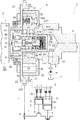
図1から図3に示すように、駆動側回転体としての外部ロータ20と、従動側回転体としての内部ロータ30と、作動流体としての作動油を制御する電磁制御弁Vとを備えて弁開閉時期制御装置Aが構成されている。
(Basic configuration)
As shown in FIGS. 1 to 3, the valve includes an
内部ロータ30(従動側回転体の一例)は、弁開閉用の吸気カムシャフト5の回転軸芯Xと同軸芯に配置され、この吸気カムシャフト5と一体回転するように連結ボルト40(バルブケースの一例)により吸気カムシャフト5に連結される。外部ロータ20(駆動側回転体の一例)は、回転軸芯Xと同軸芯に配置され、内燃機関としてのエンジンEのクランクシャフト1と同期回転する。外部ロータ20が内部ロータ30を内包しており、外部ロータ20に対して内部ロータ30は相対回転自在に支持されている。
The internal rotor 30 (an example of a driven-side rotating body) is disposed coaxially with the rotation axis X of the
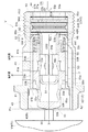
電磁制御弁Vは、エンジンEに支持される電磁ユニットVaを備えると共に、連結ボルト40の内部空間40Rに収容された弁ユニットVbとを備える。
The electromagnetic control valve V includes an electromagnetic unit Va supported by the engine E and a valve unit Vb housed in the
電磁ユニットVaは、ソレノイド部50と、プランジャ51とを備えている。このプランジャ51は、ソレノイド部50の駆動制御により出退作動するように回転軸芯Xと同軸芯に配置されている。弁ユニットVbは、作動油(流体の一例)の給排を制御するスプール55を回転軸芯Xと同軸芯に配置している。
The electromagnetic unit Va includes a
この構成から、ソレノイド部50に供給する電力の制御によりプランジャ51の突出量が設定され、これに連係してスプール55が回転軸芯Xに沿う方向に操作される。その結果、スプール55で作動油が制御され、外部ロータ20と内部ロータ30との相対回転位相が決まり、吸気バルブ5Vの開閉時期の制御を実現する。この電磁制御弁Vの構成と、作動油の制御形態は後述する。
With this configuration, the amount of protrusion of the
図1のエンジンE(内燃機関の一例)は、乗用車などの車両に備えられるものを示している。エンジンEは、上部位置のシリンダブロック2のシリンダボアの内部にピストン3を収容し、このピストン3とクランクシャフト1とをコネクティングロッド4で連結した4サイクル型に構成されている。エンジンEの上部には吸気バルブ5Vを開閉作動させる吸気カムシャフト5と、図示されない排気カムシャフトとを備えている。
The engine E (an example of an internal combustion engine) in FIG. 1 is provided in a vehicle such as a passenger car. The engine E has a four-cycle type in which a
吸気カムシャフト5を回転自在に支持するエンジン構成部材10には、エンジンEで駆動される油圧ポンプPからの作動油を供給する供給流路8が形成されている。油圧ポンプPは、エンジンEのオイルパン11に貯留される潤滑油を、供給流路8を介して作動油として電磁制御弁Vに供給する。
A supply passage 8 for supplying hydraulic oil from a hydraulic pump P driven by the engine E is formed in an
エンジンEのクランクシャフト1に形成した出力スプロケット6と、外部ロータ20のタイミングスプロケット22Sとに亘ってタイミングチェーン7が巻回されている。これにより外部ロータ20は、クランクシャフト1と同期回転する。なお、排気側の排気カムシャフトの前端にもスプロケットが備えられ、このスプロケットにもタイミングチェーン7が巻回される。
The
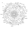
図2に示すように、クランクシャフト1からの駆動力により外部ロータ20が駆動回転方向Sに向けて回転する。内部ロータ30が外部ロータ20に対して駆動回転方向Sと同方向に相対回転する方向を進角方向Saと称し、この逆方向を遅角方向Sbと称する。この弁開閉時期制御装置Aでは、相対回転位相が進角方向Saに変位する際に変位量の増大に伴い吸気圧縮比を高め、相対回転位相が遅角方向Sbに変位する際に変位量の増大に伴い吸気圧縮比を低減するようにクランクシャフト1と吸気カムシャフト5との関係が設定されている。
As shown in FIG. 2, the
なお、この実施形態では、吸気カムシャフト5に備えた弁開閉時期制御装置Aを示しているが、弁開閉時期制御装置Aは排気カムシャフトに備えてもよい。また、弁開閉時期制御装置Aは吸気カムシャフト5と排気カムシャフトとの双方に備えてもよい。
In this embodiment, the valve timing control device A provided in the
図1、図2に示すように、外部ロータ20は、外部ロータ本体21と、フロントプレート22と、リヤプレート23とを有し、これらが複数の締結ボルト24の締結により一体化されている。フロントプレート22の外周にはタイミングスプロケット22Sが形成されている。また、フロントプレート22の内周には、環状部材9を嵌め込んでおり、この環状部材9に対して連結ボルト40のボルト頭部42を圧着することにより、環状部材9と内部ロータ本体31と吸気カムシャフト5とが一体化する。
As shown in FIGS. 1 and 2, the
図2に示すように、外部ロータ本体21には径方向の内側に突出する複数の突出部21Tが一体的に形成されている。内部ロータ30は、外部ロータ本体21の突出部21Tに密接する円柱状の内部ロータ本体31と、外部ロータ本体21の内周面に接触するように内部ロータ本体31の外周から径方向の外方に突出する4つのベーン部32とを有している。
As shown in FIG. 2, a plurality of
このように外部ロータ20が内部ロータ30を内包し、回転方向で隣接する突出部21Tの中間位置で、内部ロータ本体31の外周側に複数の流体圧室Cが形成され、この流体圧室Cがベーン部32で仕切られることで、進角室Caと遅角室Cbとが区画形成される。さらに、内部ロータ30には、進角室Caに連通する進角流路33と、遅角室Cbに連通する遅角流路34とが形成されている。
As described above, the
図1、図2に示すように、外部ロータ20と内部ロータ30との相対回転位相(以下、相対回転位相と称する)を最遅角位相から進角方向Saに付勢力を作用させて進角方向Saへの変位をアシストするトーションスプリング28が、外部ロータ20と環状部材9とに亘って備えられている。
As shown in FIGS. 1 and 2, the relative rotation phase (hereinafter referred to as a relative rotation phase) between the
図1、図2に示すように、この弁開閉時期制御装置Aでは外部ロータ20と内部ロータ30との相対回転位相を最遅角位相に保持するロック機構Lを備えている。このロック機構Lは、1つのベーン部32に対し回転軸芯Xに沿う方向に出退自在に支持されるロック部材25と、このロック部材25を突出付勢するロックスプリング26と、リヤプレート23に形成したロック凹部23aとで構成されている。なお、ロック機構Lは、ロック部材25が径方向に沿って移動するようにガイドして構成してもよい。
As shown in FIGS. 1 and 2, the valve opening / closing timing control device A includes a lock mechanism L that holds the relative rotation phase between the
ロック機構Lは、相対回転位相が、最遅角位相に達した場合にロック部材25がロックスプリング26の付勢力によりロック凹部23aに係合してロック状態に達する。また、ロック機構Lは、進角流路33に作用する作動油の圧力をロック部材25にロック解除方向に作用させることでロック解除される。
When the relative rotation phase reaches the most retarded phase, the lock mechanism L engages with the
〔連結ボルト〕
図3から図5に示すように連結ボルト40は、全体的に筒状となるボルト本体41の外端部(電磁ユニットVaに対向する側)にボルト頭部42が形成されている。また、ボルト本体41におけるボルト頭部42とは反対の側の外周に雄ネジ部41Sが形成されている。
[Connection bolt]
As shown in FIGS. 3 to 5, the
連結ボルト40の内部には回転軸芯Xに沿う方向に貫通する、円筒状の内部空間40Rが形成されている。これにより、連結ボルト40は、バルブケースとして内部空間40Rに弁ユニットVbを収容することができる。
Inside the
以下では、弁開閉時期制御装置Aの各部の方向や相対的な位置関係を説明する場合に、回転軸芯Xに沿う方向でボルト本体41の雄ネジ部41Sの側、すなわち吸気カムシャフト5側をネジ部側と称する場合がある。また、回転軸芯Xに沿う方向でボルト本体41のボルト頭部42の側、すなわち、連結ボルト40を介して吸気カムシャフト5側の他端側となる電磁ユニットVaに対向する側を頭部側と称する場合がある。なお、これらネジ部側と頭部側とはそれぞれ、供給流路8を介して供給される作動油の通流方向の上流側と下流側とに対応する。
In the following, when describing the direction and relative positional relationship of each part of the valve opening / closing timing control device A, the side of the
図1に示すように、吸気カムシャフト5には回転軸芯Xを中心にするシャフト内空間5Rが形成され、このシャフト内空間5Rの内周に雌ネジ部5Sが形成されている。シャフト内空間5Rは、前述した供給流路8と連通する。
As shown in FIG. 1, the
この構成から、ボルト本体41を環状部材9と外部ロータ20と内部ロータ30とに挿通する状態で、その雄ネジ部41Sを吸気カムシャフト5の雌ネジ部5Sに螺合させ、ボルト頭部42の回転操作により内部ロータ30が吸気カムシャフト5に締結される。この締結により環状部材9と内部ロータ30とが吸気カムシャフト5に固定され、シャフト内空間5Rと連結ボルト40の内部空間40Rとが連通する。
With this configuration, with the bolt
図4、図5に示すように、連結ボルト40の内部空間40Rの内周面のうち、頭部側の部分には、大径部40Rbが形成されている。
As shown in FIGS. 4 and 5, a large-
連結ボルト40の内部空間40Rの内周面のうち回転軸芯Xに沿う方向でのネジ部側の端部には回転軸芯Xに近接する方向に突出する(内部空間40Rの内側に向けて突出する)規制壁44が形成されている。規制壁44は、当該内周面状に円環状の壁として設けられている。
At the inner peripheral surface of the
連結ボルト40の内周で中間位置から大径部40Rbの先端(連結ボルト40)に達する領域には複数(4つ)のドレン溝Dが回転軸芯Xに沿う姿勢で形成される。
A plurality (four) of drain grooves D are formed in the inner circumference of the
ボルト本体41には、進角流路33に連通する進角ポート41aと、遅角流路34に連通する遅角ポート41bとが外周面から内部空間40Rに亘って形成されている。
In the bolt
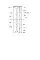
〔弁ユニット〕
図3から図5に示すように弁ユニットVbは、連結ボルト40の内部空間40Rのうち、ボルト本体41の内周面に密着する状態で嵌め込まれるスリーブ53と、回転軸芯Xと同軸芯で内部空間40Rに収容される流体供給管54と、スリーブ53の内周面と流体供給管54の管路部54Tの外周面に案内される状態で回転軸芯Xに沿う方向にスライド移動自在に配置されるスプール55とを備えている。
[Valve unit]
As shown in FIGS. 3 to 5, the valve unit Vb includes a
さらに、弁ユニットVbは、スプール55を突出方向に付勢する付勢部材としてのスプールスプリング56と、第一逆止弁CV1と、第二逆止弁CV2と、フィルタ59と、固定リング60と、先端リング61と、を備えている。
Further, the valve unit Vb includes a
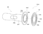
第一逆止弁CV1は、流体供給管54の基端部54S及び第一弁プレート52によって構成される。第二逆止弁CV2は、開口プレート57及び第二弁プレート58によって構成される。
The first check valve CV <b> 1 is configured by the
固定リング60は、内部空間40Rに嵌る外筒部60aと、円筒状の外筒部60aよりも内径の小さな内筒部60bと、固定リング60における、回転軸芯Xに沿う方向のおよそ中間位置に、回転軸芯Xと垂直に交差する壁部60cとを有する。壁部60cには、回転軸芯Xを中心とする円形の開口部60dが形成されている。
The fixing
先端リング61は、内部空間40Rに嵌る外筒部61aと、外筒部61aのネジ部側に、回転軸芯Xと垂直に交差する壁部61bとを有する。壁部61bには、回転軸芯Xを中心とする開口部61cが形成されている。
The
〔弁ユニット:スリーブ〕
図3から図5に示すようにスリーブ53は、回転軸芯Xを中心とする筒状の部材である。スリーブ53は、頭部側に、スリーブ53の筒の外周から回転軸芯Xに沿う方向に交差する向きに突出する複数(2つ)の係合突起53Tを有している。また、スリーブ53は、ネジ部側を回転軸芯Xに直交する姿勢に屈曲させて端部壁53Wを絞り加工等により形成している。
[Valve unit: Sleeve]
As shown in FIGS. 3 to 5, the
係合突起53Tがドレン溝Dに嵌ることにより回転軸芯Xを中心にしたスリーブ53の姿勢が定まり、後述するドレン孔53cおよびドレン孔53dがドレン溝Dに連通する状態が維持される。
The engagement of the
スリーブ53には、進角ポート41aを内部空間40Rに連通させる複数の進角連通孔53aと、遅角ポート41bに内部空間40Rを連通させる複数の遅角連通孔53bと、内部空間40Rの作動油をスリーブ53の外面側に排出する複数のドレン孔53cとが角孔状(矩形)に形成されている。ドレン孔53cは、スリーブ53におけるネジ部側に形成されている。スリーブ53は、頭部側にもドレン孔53dが形成されている。
The
進角連通孔53a及び遅角連通孔53bは、回転軸芯Xを中心とする周方向の4箇所に分散配置されており、回転軸芯Xに沿う方向に並列して形成されている。
The advance
ドレン孔53c及びドレン孔53dは、回転軸芯Xを中心とする周方向の4箇所に分散配置されており、進角連通孔53a及び遅角連通孔53bとは異なる位相となるように形成されている。
The
周方向においてそれぞれのドレン孔53cとドレン孔53dとは、同一の位相において一対に設けられている。つまり、一対のドレン孔53cとドレン孔53dとが、回転軸芯Xに沿う方向に並んで配置されている。
In the circumferential direction, the drain holes 53c and the
前述した係合突起53Tは、4つドレン孔53cのうち回転軸芯Xを挟んで対向する位置の2つのものを基準に回転軸芯Xに沿う方向での延長線上に配置されている。
The
スリーブ53は、係合突起53Tをドレン溝Dに沿わせた状態で、連結ボルト40の内部空間40Rに嵌め込まれる。こうすることで、バルブケースとしての連結ボルト40のドレン溝Dが、連結ボルト40とスリーブ53との間に配置され、連結ボルト40とスリーブ53との間に、ドレン溝Dの溝の内周面とスリーブ53の外周面とで囲われた空間連通路を形成することができる。ドレン溝Dは、連結ボルト40のボルト頭部42の端面に達する領域に亘って形成されているため、空間連通路は、連結ボルト40の外部に連通して形成される。
The
また、進角連通孔53aと進角ポート41aとが連通する。また、遅角連通孔53bと遅角ポート41bとが連通しする。また、ドレン孔53cおよびドレン孔53dがドレン溝Dに連通する状態が維持される。
Further, the
これにより、弁ユニットVbにおいて、スリーブ53とスプール55との間の空間(一対のランド部55bよりも吸気カムシャフト5側の空間)と、スプール55(スプール本体55aの外周)と壁部61bの吸気カムシャフト5の側との間の空間(一対のランド部55bよりも電磁ユニットVaに対向する側の空間)とが、連結ボルト40とスリーブ53との間に形成された空間連通路としてのドレン溝Dと連通する。
Thus, in the valve unit Vb, the space between the
〔弁ユニット:流体供給管〕
図3から図5に示すように流体供給管54は、内部空間40Rに嵌め込まれる基端部54S、および、基端部54Sより小径で、基端部54Sから内部空間40Rにおける頭部側に向けて延出する管路部54Tが一体形成され、この管路部54Tの先端部の外周には供給口54aが形成されている。
[Valve unit: Fluid supply pipe]
As shown in FIGS. 3 to 5, the
基端部54Sは、回転軸芯Xを中心として内部空間40Rに嵌る直径の円形であって、回転軸芯Xに直交する姿勢で設けられ、管路部54Tとの境界近傍に循環孔54bが形成されて構成されている。
The
管路部54Tの先端部の外周に形成される3つの供給口54aは、回転軸芯Xに沿う方向に伸びる長孔状である。また、スプール55に形成される4つの中間孔部55cは円形状である。そして、供給口54aの数と、スプール55に形成される中間孔部55cの数とが異なり、供給口54aの周方向での開口幅が、周方向で隣接する供給口54aの中間部分(管路部54Tの部分のうち、周方向で隣り合う供給口54a、54aの間にある部分)の幅より大きく形成されている。これにより、管路部54Tからの作動油を、中間孔部55cに対して確実に供給することができる。
The three
基端部54Sには、第一逆止弁CV1の一部を成す循環孔54bが形成されている。循環孔54bは、回転軸芯Xを中心とし、管路部54Tの外周に沿う環状領域に、一対の貫通口が回転軸芯Xを中心に対称となる円弧状に配置されている。本実施形態では、循環孔54bは、円弧状に形成された二つのスリット状の貫通口である。
A
〔弁ユニット:スプール,スプールスプリング〕
図3から図5に示すようにスプール55は、筒状で形成されている。スプール55は、先端に操作端部55sが形成されたスプール本体55aを有する。スプール本体55aの外周には、突出状態で形成された一対のランド部55bが形成されている。また、スプール本体55aの外周には、一対のランド部55bの中間位置とスプール55の内部とを連通させる複数(4つ)の中間孔部55cが形成されている。操作端部55sと一対のランド部55bの電磁ユニットVaに対向する側との間には、回転軸芯Xと交差(本実施形態では直交)する方向でスプール本体55aを貫通するドレン貫通孔55hが設けられている。
[Valve unit: spool, spool spring]
As shown in FIGS. 3 to 5, the
スプール55のうち、操作端部55sとは反対の側には、スプール55が押し込み方向に操作された際に、端部壁53Wに当接して作動限界を決める当接端部55rがランド部55bと一体となって形成されている。この当接端部55rは、スプール本体55aを延長した領域の端部においてランド部55bより小径に構成される。
On the side of the
スプールスプリング56は、圧縮コイル型であり、内部側のランド部55bとスリーブ53の端部壁53Wとの間に配置されている。この付勢力の作用により、スプール55は頭部側のランド部55bが壁部61bに当接して図3に示す進角ポジションPaに維持される。頭部側のランド部55bは壁部61b側に延出する小径部55dを有しており、この小径部55dが壁部61bに当接する。
The
さらに、弁ユニットVbでは、スリーブ53の端部壁53Wと、流体供給管54の基端部54Sとが回転軸芯Xに沿う方向で互いに当接するように位置関係が設定されている。端部壁53Wと基端部54Sとは、このように当接する端部壁53Wと基端部54Sとの平面精度を高くすることにより作動油の流れを阻止するシール部Hとして構成されている。
Further, in the valve unit Vb, the positional relationship is set such that the
なお、端部壁53Wは管路部54Tの外周面に対して離間して設けられ、両者の間に隙間が形成されている。進角室Caもしくは遅角室Cbからスリーブ53とスプール55との間の空間に排出された作動油が、当該隙間と循環孔54bとを経由して流体供給管54に流通(還流)可能となっている。
The
この構成では、流体供給管54の基端部54Sの位置が固定リング60によって固定されるようになっている。そのため、この基端部54Sがリテーナとして機能する。
In this configuration, the position of the
また、スリーブ53の端部壁53Wにはスプールスプリング56の付勢力が作用するため、端部壁53Wが基端部54Sを圧接する。
Further, since the urging force of the
従って、端部壁53Wと基端部54Sとが互いに密着できるように互いの姿勢を設定することで、スプールスプリング56の付勢力を利用して端部壁53Wを基端部54Sに密着させ、この部位をシール部Hとして構成するのである。
Therefore, by setting the posture of the
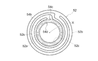
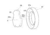
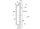
〔第一逆止弁〕
図5〜図7に示すように、第一逆止弁CV1を構成する基端部54S(弁座の一例)と第一弁プレート52(弁体の一例)とは等しい外径の金属材で形成されている。基端部54Sのネジ部側で基端部54Sに接する位置に第一弁プレート52を配置している。特に第一弁プレート52にはバネ板材が用いられている。
(First check valve)
As shown in FIGS. 5 to 7, the
基端部54Sは、回転軸芯Xを中心とする環状領域に2つの循環孔54b(流通孔の一例)が回転軸芯Xを中心に対称となる円弧状に成されている。こうして、基端部54Sに複数の循環孔54bが環状に配置されることで構成される流通部F1が設けられる。また、基端部54Sのうち第一弁プレート52に対向する面で、循環孔54bを取り囲む外側領域に回転軸芯Xを中心に環状の突起54c(外周突起、第1突起部の一例)が形成され、循環孔54bよりも径方向内方側に回転軸芯Xを中心に環状の突起54d(内周突起、第1突起部の一例)が形成されている。
The
第一弁プレート52は、循環孔54bを閉塞可能な環状の閉塞部52aと、閉塞部52aを保持する弁体保持部として、閉塞部52aを囲む環状の保持部52bと、閉塞部52aと保持部52bとを接続するように設けられたばね部52sとを有する。ばね部52sは、保持部52bに対し閉塞部52aの回転軸芯Xに沿う方向への相対移動を許容する。環状の閉塞部52aは、第一弁プレート52の中央位置に回転軸芯Xを中心として配置され、保持部52bは、第一弁プレート52の外周側に回転軸芯Xを中心として配置されている。ばね部52sは、閉塞部52aと保持部52bとを繋ぐように渦巻き状に形成されている。閉塞部52aは、外径側が前述した循環孔54bの環状領域より大径であって、内径側には循環孔54bの環状領域より小径の開口部52cが形成されている。この構成では、開口部52cが回転軸芯Xを中心とする円形に形成される。これにより、第一弁プレート52は、閉塞部52aが突起54c,54dに当接して密着したときに循環孔54bを閉塞することができる。
The
第一弁プレート52は、図3から図4に示すように、保持部52bを、固定リング60の外筒部60aと基端部54Sとで挟持されて内部空間40Rで固定される。
As shown in FIGS. 3 and 4, the
このような構成から、第一逆止弁CV1を組み立てる際には、連結ボルト40の内部空間40Rに、固定リング60、第一弁プレート52、流体供給管54の順に嵌め込むだけで、各々が最適な位置関係となり、位置決め等の操作が不要となる。
From such a configuration, when assembling the first check valve CV1, only the fixing
第一逆止弁CV1は、第一逆止弁CV1に流体が流れる方向からみて下流側となるネジ部側の圧力よりも、上流側となるスリーブ53とスプール55との間の空間の圧力が高くなった場合に開弁される。具体的には、図3に示すように、作動油の圧力でばね部52s(図7参照)が弾性変形することにより、閉塞部52aが循環孔54bから離間する。これにより、スリーブ53とスプール55との間の空間の作動油が循環孔54bを経由して流体供給管54に流通する。閉塞部52aは固定リング60の内筒部60bの内側を、回転軸芯Xに沿い、固定リング60の壁部60cまでの範囲で前後に揺動する。
The first check valve CV1 has a higher pressure in the space between the
第一逆止弁CV1は、ネジ部側の圧力がスリーブ53とスプール55との間の空間の圧力よりも上回った場合、あるいは、スプール55が中立ポジションPnに設定された場合には、図4に示すように、ばね部52sの弾性復帰力及び流体供給管54に流入する作動油の圧力により閉塞部52aが突起54c,54dに当接(密着)して循環孔54bを閉塞する。その結果、ネジ部側からスリーブ53とスプール55との間の空間への作動油の流入が防止される。
The first check valve CV1 is activated when the pressure on the screw part side exceeds the pressure in the space between the
基端部54Sには回転軸芯Xを中心に対称となる形状の2つの循環孔54bが形成されているため、閉塞部52aに偏りのない圧力を作用させて閉塞部52aを確実に突起54c,54dから離間させ、循環孔54bを開放させることができる。こうして一対の循環孔54bを通過して基端部54Sのネジ部側空間に流出した作動油は、閉塞部52aの内周側の開口部52cを介して流体供給管54に送り込む(循環させる)ことが可能となる。
Since two
このように構成することで、バネ板材を用いつつ、第一逆止弁CV1を小型化し、連結ボルト40の内部空間40Rに収容することができる。また、例えば、連結ボルト40の外部に逆止弁を備える構成と比較して、流路構成を簡素化することができる。また、この第一逆止弁CV1は進角室Caや遅角室Cbに連通する流路の近傍に配置されるため、応答性良く閉塞作動させることも可能となる。
With this configuration, the first check valve CV <b> 1 can be reduced in size while being used in the spring plate, and can be accommodated in the
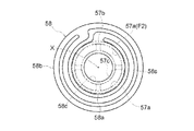
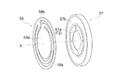
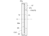
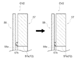
〔第二逆止弁〕
図5、図8、図9に示すように、第二逆止弁CV2を構成する開口プレート57(弁座の一例)と第二弁プレート58とは等しい外径に形成され、作動油の供給方向での上流側に開口プレート57を配置し、これより下流側で開口プレート57に接する位置に第二弁プレート58を配置している。第二弁プレート58にはバネ板材が用いられている。
(Second check valve)
As shown in FIGS. 5, 8, and 9, the opening plate 57 (an example of a valve seat) and the
開口プレート57は回転軸芯Xを中心とする環状領域に4つの流通孔57aが回転軸芯Xを中心に対称となる円弧状に形成されている。こうして、開口プレート57に複数の流通孔57aが環状に配置されることで構成される流通部F2が設けられる。また、開口プレート57のうち第二弁プレート58に対向する面で、流通孔57aを取り囲む外側領域に回転軸芯Xを中心に環状の突起57b(外周突起、第1突起部の一例)が形成され、流通孔57aよりも径方向内方側に回転軸芯Xを中心に環状の突起57c(内周突起、第1突起部の一例)が形成されている。
In the opening
第二弁プレート58は、流通孔57aを閉塞可能な環状の閉塞部58aと、閉塞部58aを保持する弁体保持部として、閉塞部52aを囲む環状の保持部58bと、閉塞部58aと保持部58bとを接続するように設けられたばね部58sとを有する。ばね部58sは、保持部58bに対し閉塞部58aの回転軸芯Xに沿う方向への相対移動を許容する。環状の閉塞部58aは、第二弁プレート58の中央位置に回転軸芯Xを中心として配置され、保持部58bは、第二弁プレート58の外周側に回転軸芯Xを中心として配置されている。ばね部58sは、閉塞部58aと保持部58bとを繋ぐように渦巻き状に形成されている。閉塞部58aは、外径側が前述した流通孔57aの環状領域より大径であって、内径側には流通孔57aの環状領域より小径の開口部58cが形成されている。この構成では、開口部58cが回転軸芯Xを中心とする円形に形成される。これにより、閉塞部58aは、突起57b、57cに当接して密着したときに流通孔57aを閉塞することができる。
The
第二弁プレート58は、保持部58bを、固定リング60の外筒部60aと開口プレート57とで挟持されている。
In the
このような構成から、第二逆止弁CV2を組み立てる際には、連結ボルト40の内部空間40Rに、開口プレート57、第二弁プレート58、固定リング60の順に嵌め込むだけで、各々が最適な位置関係となり、位置決め等操作が不要となる。
With such a configuration, when assembling the second check valve CV2, it is only necessary to fit the opening
また、第二逆止弁CV2では、油圧ポンプPから供給流路8を介してシャフト内空間5Rに作動油が供給された場合には、図3に示すように、ばね部58sが弾性変形することにより、閉塞部58aが流通孔57aから離間して作動油が流体供給管54に流入するのを許容する。
閉塞部58aは固定リング60の内筒部60bの内側を、回転軸芯Xに沿い、固定リング60の壁部60cまでの範囲で前後に揺動する。
Further, in the second check valve CV2, when hydraulic oil is supplied from the hydraulic pump P to the shaft
The closing
第二逆止弁CV2では、第二逆止弁CV2よりも下流側となる頭部側の圧力が上昇した場合や、油圧ポンプPの吐出圧が低下した場合、あるいは、スプール55が中立ポジションPnに設定された場合には、図4に示すように、ばね部58sの弾性力により閉塞部58aが開口プレート57の突起57b、57cに密着して流通孔57aを閉塞する。その結果、下流側から上流側への作動油の逆流が防止される。また、閉塞部58aは開口プレート57の突起57b,57cだけに当接して流通孔57aを閉塞するので、閉塞部58aが開口プレート57に密着して離れ難くなる不都合を抑制する。
In the second check valve CV2, when the pressure on the head side downstream of the second check valve CV2 increases, when the discharge pressure of the hydraulic pump P decreases, or when the
〔フィルタ〕
フィルタ59は、開口プレート57と第二弁プレート58と等しい外径の環状の枠体59aの中央部が作動油の流通を許容する網状部材で成る濾過部59bを備えて構成されている。
〔filter〕
The
フィルタ59は、連結ボルト40の内部空間40Rの規制壁44と環状の支持部材59cとの間に挟み込まれて保持される。支持部材59cは、開口プレート57により規制壁44に押し付けられて保持される。
The
このように第二逆止弁CV2が構成されるため小型化が可能となる。しかも、図3に示すように、第二逆止弁CV2が開弁する状態にある場合には、開口プレート57に形成された4つの流通孔57aを流れた作動油が、閉塞部58aの内周側の開口部58cおよび開口部60dを流通して流体供給管54の管路部54Tに流入する。本実施形態においては、流通孔57aを通過した作動油が回転軸芯Xと同軸芯にある円形の開口部58cと円形の開口部60dを経由して管路部54Tに流入するので、圧損を抑制した状態での作動油の供給を実現する。
Since the second check valve CV2 is configured as described above, the size can be reduced. Further, as shown in FIG. 3, when the second check valve CV2 is in the open state, the hydraulic oil flowing through the four
また、開口プレート57には回転軸芯Xを中心に対称となる形状の4つの流通孔57aが形成されるため、閉塞部58aに偏りのない圧力を作用させて閉塞部58aを確実に突起57b,57cから離間させ、流通孔57aを開放させると共に、4つの流通孔57aを通過した作動油を閉塞部58aの開口部58cに送り込むことができる。
In addition, since four
特に、第二逆止弁CV2が連結ボルト40の内部空間40Rに収容されているため、例えば、連結ボルト40の外部に備える構成と比較して、流路構成が簡素化し、第二逆止弁CV2を進角室Caや遅角室Cbに連通する流路の近傍に配置されるため、応答性良く閉塞作動させることも可能となる。
In particular, since the second check valve CV2 is housed in the
〔弁ユニット、第一逆止弁、第二逆止弁およびフィルタの組立〕
図5に示すように、まず、フィルタ59を内部空間40Rの頭部側から挿入し、規制壁44に当接させる。その後、支持部材59c、開口プレート57、第二弁プレート58、固定リング60、第一弁プレート52、流体供給管54を、この順に内部空間40Rに挿入し、それぞれ当接させる。
[Assembly of valve unit, first check valve, second check valve and filter]
As shown in FIG. 5, first, the
さらに、スリーブ53の係合突起53Tをドレン溝Dに嵌めて、スリーブ53を内部空間40Rに挿入し、スリーブ53の端部壁53Wを流体供給管54の基端部54Sに当接させる。
Further, the
さらにスプールスプリング56、およびスプール55を、この順に、流体供給管54の管路部54Tの外側から嵌めて、内部空間40Rに挿入する。
Further, the
最後に、先端リング61を、ネジ部側に向けて、内部空間40Rに圧入する。この圧入の際、スプール55のスプール本体55aを、先端リング61の開口部61cに挿入し、頭部側位置のランド部55bの小径部55dを先端リング61の壁部61bに押し当てて、スプール本体55aの頭部側の先端部分が、先端リング61よりも頭部側に突出した状態とする。そして、ネジ部側位置のランド部55bを頭部側に向けて付勢するスプールスプリング56の付勢力に抗しつつ、先端リング61を内部空間40Rの奥まで圧入する。
Finally, the
先端リング61の圧入が完了すると、先端リング61と、規制壁44との間で、頭部側からネジ部側に向けて、スプール55、スプールスプリング56、スリーブ53、流体供給管54、第一逆止弁CV1、固定リング60、第二逆止弁CV2、フィルタ59が内部空間40Rにおいて位置決めされる。
When the press-fitting of the
〔作動油の制御形態〕
この弁開閉時期制御装置Aでは電磁ユニットVaのソレノイド部50に電力が供給されない状態では、プランジャ51からスプール55に押圧力が作用することはなく、図3に示すようにスプールスプリング56の付勢力によりスプール55は、その外側位置のランド部55bの小径部55dが壁部61bに当接する位置に維持される。
[Control form of hydraulic oil]
In the valve opening / closing timing control device A, when power is not supplied to the
このスプール55の位置が進角ポジションPaであり、一対のランド部55bと進角連通孔53aおよび遅角連通孔53bとの位置関係から、スプール55の中間孔部55cと進角連通孔53aとが連通し、遅角連通孔53bがスリーブ53の内側の空間(内部空間40R)に連通する。
The position of the
これにより、油圧ポンプPから供給される作動油が、流体供給管54の供給口54aからスプール55の中間孔部55cと進角連通孔53aと進角ポート41aとを介して、進角室Caに供給される。
Thereby, the working oil supplied from the hydraulic pump P is supplied from the
このとき、第二逆止弁CV2は、開口プレート57の側から第二弁プレート58に向けて流体圧を受けており、この流体圧により、第二弁プレート58の閉塞部58aが開口プレート57から離間して開弁状態になっている。第二逆止弁CV2は、閉弁状態(図8、図9参照)において、閉塞部58aが開口プレート57の環状の突起57b、57cにのみ当接しているため、両者の当接面積は小さい。そのため、閉塞部58aと開口プレート57とが当接する閉弁状態から開弁状態に移行する際に、両者の間に表面張力が作用し難い。したがって、閉塞部58aを、開口プレート57の突起57b、57cから容易に離間させて開弁させることができる。このように、閉塞部58aに対して流体圧が作用し易く、第二逆止弁CV2は迅速な開弁動作が可能になるため、作動油を弁開閉時期制御装置Aに迅速に供給することができる。
At this time, the second check valve CV2 receives fluid pressure from the side of the opening
このとき、遅角室Cbの作動油は、遅角ポート41bから遅角連通孔53bを介してスリーブ53とスプール55との間の空間に排出される。
At this time, the hydraulic oil in the retard chamber Cb is discharged from the
スリーブ53とスプール55との間の空間に排出された作動油の一部は、第一逆止弁CV1を介して、流体供給管54へ循環される。循環された作動油は、油圧ポンプPから供給される作動油と共に、進角室Caに供給される。この作動油の循環により、進角室Caに作動油が迅速に供給される。
A part of the hydraulic oil discharged into the space between the
このとき、第一逆止弁CV1は、流体供給管54の側から第一弁プレート52に向けて流体圧を受けており、この流体圧により、第一弁プレート52の閉塞部52aが流体供給管54の基端部54Sから離間して開弁状態になっている。第一逆止弁CV1は、閉弁状態(図6、図7参照)において、閉塞部52aが基端部54Sの環状の突起54c、54dにのみ当接しているため、両者の当接面積は小さい。そのため、閉塞部52aと基端部54Sとが当接する閉弁状態から開弁状態に移行する際に、両者の間に表面張力が作用し難い。したがって、閉塞部52aを、基端部54Sの突起54c、54dから容易に離間させて開弁させることができる。このように、閉塞部52aに対して流体圧が作用し易く、第一逆止弁CV1は迅速な開弁動作が可能になるため、作動油を流体供給管54に迅速に還流させることができる。
At this time, the first check valve CV1 receives fluid pressure from the
スリーブ53とスプール55との間の空間に排出された作動油の残りは、ドレン孔53cに流れ、ドレン溝Dを介して連結ボルト40の頭部側の端部から外部に排出される。
The rest of the hydraulic oil discharged into the space between the
この作動油の給排および循環の結果、相対回転位相が進角方向Saに速やかに変位する。特に、ロック機構Lがロック状態にある場合には、スプール55を進角ポジションPaに設定することにより、進角室Caに供給される作動油の一部が進角流路33からロック機構Lに供給され、ロック部材25をロック凹部23aから離脱させてロック解除も実現する。
As a result of the supply and discharge and circulation of the hydraulic oil, the relative rotational phase is quickly displaced in the advance direction Sa. In particular, when the lock mechanism L is in the locked state, by setting the
電磁ユニットVaのソレノイド部50に所定の電力を供給することにより、プランジャ51を突出作動させ、スプールスプリング56の付勢力に抗してスプール55を図4に示す中立ポジションPnに設定することが可能である。
By supplying predetermined power to the
スプール55が中立ポジションPnに設定された場合には、一対のランド部55bがスリーブ53の進角連通孔53aと遅角連通孔53bとを閉じる位置関係となり、進角室Caと遅角室Cbとに作動油が給排されず相対回転位相が維持される。
When the
電磁ユニットVaのソレノイド部50に中立ポジションPnに設定する電力を超える電力を供給することにより、プランジャ51をさらに突出作動させ、スプール55を不図示の遅角ポジションに設定することが可能である。
By supplying power exceeding the power set at the neutral position Pn to the
遅角ポジションでは、油圧ポンプPから供給される作動油が、流体供給管54の供給口54aからスプール55の中間孔部55cと遅角連通孔53bと遅角ポート41bとを介して遅角室Cbに供給される。
In the retard position, the hydraulic oil supplied from the hydraulic pump P is supplied from the
これと同時に、進角室Caの作動油が進角ポート41aから進角連通孔53aを介してスプール本体55aの外周と壁部61bの吸気カムシャフト5側との間の空間に排出される。
At the same time, the hydraulic oil in the advance chamber Ca is discharged from the
スプール本体55aの外周と壁部61bの吸気カムシャフト5側との間の空間に排出された作動油の一部は、当該空間から、ドレン孔53d、ドレン溝D、およびドレン孔53cを介してスリーブ53とスプール55との間の空間に流入する。スリーブ53とスプール55との間の空間に流入した作動油は、第一逆止弁CV1を介して、流体供給管54へ循環される。循環された作動油は、油圧ポンプPから供給される作動油と共に、遅角室Cbに供給される。この作動油の循環により、遅角室Cbに作動油が迅速に供給される。
A part of the hydraulic oil discharged into the space between the outer periphery of the
スプール本体55aの外周と壁部61bの吸気カムシャフト5側との間の空間に排出された作動油の残りは、ドレン孔53dおよびドレン溝Dを介して外部に排出される。こうした作動油の給排および循環の結果、相対回転位相が遅角方向Sbに速やかに変位する。
The remainder of the hydraulic oil discharged into the space between the outer periphery of the
〔第二逆止弁の変形例1〕
以下に、第二逆止弁CV2の変形例を示す。ただし、以下に示す構成は、第二逆止弁CV2に限られず、第一逆止弁CV1の構成として用いてもよい。図10に示すように、第二逆止弁CV2は、第二弁プレート58の保持部58bを閉塞部58aと開口プレート57の突起57b、57cとの当接位置よりも回転軸芯Xに沿う方向で当該第1突起57b、57cの基部側に固定されている。
[
Hereinafter, a modified example of the second check valve CV2 will be described. However, the configuration shown below is not limited to the second check valve CV2, and may be used as the configuration of the first check valve CV1. As shown in FIG. 10, the second check valve CV <b> 2 moves the holding
本変形例1によれば、閉弁状態において、閉塞部58aと保持部58bとを接続するばね部58sは保持部58bから閉塞部58aに向けて撓んだ状態となり、ばね部58sから閉塞部58aには回転軸芯Xに沿う方向において開口プレート57を押し付ける弾性力が付与される。このような構成であれば、開弁状態から閉弁状態に移行する際には、ばね部58sによる弾性力の作用により閉塞部58aを迅速に突起57b、57cに当接させることができるので、閉弁までの時間を短くすることができる。
According to the first modification, in the valve closed state, the
〔第二逆止弁の変形例2〕
図11、図12に示すように、第二逆止弁CV2は、第二弁プレート58において閉塞部58aが円板状に形成され、開口プレート57には流通孔57aの外周側のみに環状の突起57b(外周突起の一例)が設けられている。
[
As shown in FIGS. 11 and 12, the second check valve CV <b> 2 has a closing
〔第二実施形態〕
以下、本発明に係る弁開閉時期制御装置Aの第二実施形態について説明する。第二実施形態は、第一実施形態とは第二逆止弁CV2の構成が異なり、他の構成は第一実施形態と同じである。そこで、以下では、第二逆止弁CV2の構成についてのみ説明する。ただし、以下に示す構成は、第二逆止弁CV2に限られず、第一逆止弁CV1の構成として用いてもよい。
(Second embodiment)
Hereinafter, a second embodiment of the valve timing control apparatus A according to the present invention will be described. The second embodiment is different from the first embodiment in the configuration of the second check valve CV2, and the other configuration is the same as the first embodiment. Therefore, only the configuration of the second check valve CV2 will be described below. However, the configuration shown below is not limited to the second check valve CV2, and may be used as the configuration of the first check valve CV1.
図13、図14に示すように、第二逆止弁CV2は、開口プレート57と、第二弁プレート58とを備える。第二弁プレート58は、円板状であって閉塞部58aのみで構成されており、外周に複数(本実施形態では3つ)の切欠き63が形成されている。開口プレート57には中央に円形の流通孔57aが貫通形成され、流通孔57aを囲む第二弁プレート58と、突起57bとを囲む位置に環状の突起57e(第2突起部の一例)が設けられている。開口プレート57に対し第二弁プレート58の全体が近接離間することで弁の開閉を行う。第二弁プレート58の開弁時には、作動油は流通孔57aと切欠き63とを経由して流体供給管54に流入する。
As shown in FIGS. 13 and 14, the second check valve CV2 includes an opening
第二逆止弁CV2においては、突起57b(第1突起部)に閉塞部58aが当接した状態で、閉塞部58aにおいて突起57b(第1突起部)と当接している面71とは反対側の面72よりも、回転軸芯Xに沿う方向で突起57e(第2突起部)が突出している。
In the second check valve CV2, in a state where the closing
このような構成にすることにより、弁ユニットVbに第二逆止弁CV2を組む付ける際に、開口プレート57に設けられた突起57eを第二弁プレート58の位置決め部として用いることができる。また、第二弁プレート58の回転軸芯Xに沿う方向への移動を突起57eによって案内することができる。その結果、突起57eによって第二弁プレート58の回転軸芯Xに沿う方向に垂直な方向の位置ずれを防止することができるので、第二弁プレート58の動作が安定し、第二逆止弁CV2における第二弁プレート58の作動性が向上する。
With this configuration, when assembling the second check valve CV2 to the valve unit Vb, the
〔第二実施形態の第二逆止弁の変形例1〕
図15に示すように、第二逆止弁CV2は、回転軸芯Xに沿う方向において、突起57e(第2突起部)の突起57b(第1突起部)に対向する側の面73が、基部74から先端部75に向かうにつれて突起57b(第1突起部)から離間するテーパ形状を有している。第二弁プレート58の形状は第二実施形態と同じである。
[Modification Example 1 of Second Check Valve of Second Embodiment]
As shown in FIG. 15, the second check valve CV2 has a
本構成のように、突起57eがテーパ形状を有することで、開口プレート57において突起57eの内側に第二弁プレート58を容易に位置決めすることができ、開口プレート57に対する第二弁プレート58の組付けが容易になる。また、開弁の際に、第二弁プレート58が突起57eに接触しづらくなるので、第二逆止弁CV2における第二弁プレート58の作動性がより向上する。
Since the
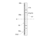
〔第二実施形態の第二逆止弁の変形例2〕
図16に示すように、第二逆止弁CV2は、突起57e(第2突起部)の先端部75に対向する位置に第二弁プレート58の回転軸芯Xに沿う方向の移動を案内するガイド部62を備える。ガイド部62は、固定リング60のネジ部側に設けられる。本変形例においては、第二逆止弁CV2は、回転軸芯Xに沿う方向において、突起57e(第2突起部)とガイド部62との間隙W1が、ゼロ以上且つ閉塞部58aの厚みW2よりも小さい。第二弁プレート58の形状は第二実施形態と同じである。
[
As shown in FIG. 16, the second check valve CV2 guides the movement of the
本構成のように、突起57eの先端部75に対向する位置に第二弁プレート58の回転軸芯Xに沿う方向の移動を案内するガイド部62を備えることで、第二弁プレート58は回転軸芯Xに沿う方向への移動がスムーズになる。また、突起57eとガイド部62との間隙W1がゼロ以上且つ閉塞部58aの厚みW2よりも小さいことで、第二弁プレート58は回転軸芯Xに直交する方向への移動が規制され、第二弁プレート58が突起57eとガイド部62との間隙に嵌り込むことがなくなる。これにより、第二逆止弁CV2において第二弁プレート58は回転軸芯Xに沿う方向への移動がより安定的になり、弁開閉時期制御装置Aの応答性が向上する。
As in the present configuration, the
〔別実施形態〕
(1)第二逆止弁CV2は、開口プレート57(弁座)のうち少なくとも第二弁プレート58に当接する突起57b,57c(第1突起部)が、第二弁プレート58(弁体)よりも低硬度の材料で形成されていてもよい。図17に示す第二逆止弁CV2では、開口プレート57において突起57bのみが第二弁プレート58(弁体)よりも低硬度の材料で形成されている。図示しないが、突起57b(第1突起部)を含む開口プレート57全体が第二弁プレート58(弁体)よりも低硬度の材料で形成されていてもよい。第一逆止弁CV1において、流体供給管54の基端部54S(弁座)のうち少なくとも第一弁プレート52に当接する突起54c、54d(第1突起部)が、第一弁プレート52(弁体)よりも低硬度の材料で形成されていてもよい。
[Another embodiment]
(1) In the second check valve CV2, at least the
このように、第二逆止弁CV2(または第一逆止弁CV1)において、開口プレート57(弁座)のうち少なくとも突起57b(第1突起部)が、第二弁プレート58(弁体)よりも低硬度の材料で形成されていると、突起57bに第二弁プレート58の閉塞部58aが当接した際のシール性が向上する。また、第二逆止弁CV2(または第一逆止弁CV1)において、当接離間する閉塞部58a及び突起57bのうち、硬度が低い突起57bにおいて摩耗が発生し、硬度が高い閉塞部58aの摩耗が抑制されるが、突起57bが摩耗しても第二弁プレート58が摩耗していないため、第二弁プレート58と突起57bとの間のシール性が継続的に確保され、第二逆止弁CV2(または第一逆止弁CV1)の耐久性が向上する。
Thus, in the second check valve CV2 (or the first check valve CV1), at least the
(2)図5に示すように、上記の実施形態では、弁ユニットVbは、第一逆止弁CV1と、第二逆止弁CV2とを備える構成を説明した。しかしながら、弁ユニットVbは、第一逆止弁CV1及び第二逆止弁CV2のいずれか一方を備えない構成とすることもできる。 (2) As shown in FIG. 5, in the above embodiment, the configuration in which the valve unit Vb includes the first check valve CV1 and the second check valve CV2 has been described. However, the valve unit Vb may be configured not to include any one of the first check valve CV1 and the second check valve CV2.
(3)上記実施形態では、弁ユニットVbは、第一逆止弁CV1と、第二逆止弁CV2とを備え、いずれの弁座(基端部54S,開口プレート57)にも第1突起部(突起54c,54d、57b,57c)有する構成を示したが、第一逆止弁CV1及び第二逆止弁CV2のうち、一方の弁座のみが弁体に当接する第1突起部を有する構成でもよい。
(3) In the above embodiment, the valve unit Vb includes the first check valve CV1 and the second check valve CV2, and the first protrusion is provided on any of the valve seats (the
(4)上記の実施形態では、第一逆止弁CV1の弁座としての基端部54Sに、第一逆止弁CV1の一部を成す循環孔54bが形成され、循環孔54bは、回転軸芯Xを中心に対称となる円弧状に2つ配置されて流通部F1を構成する例を示した。また、第二逆止弁CV2の弁座としての開口プレート57に、第二逆止弁CV2の一部を成す流通孔57aが形成され、流通孔57aは、回転軸芯Xを中心に対称となる円弧状に4つ配置されて流通部F2を構成する例を示した。
(4) In the above embodiment, a
しかしながら、循環孔54b及び流通孔57aは、2つや4つに形成される場合に限られず、1つ、3つ、5つ以上であってもよい。また、循環孔54b及び流通孔57aは、円弧状に形成されたスリット状の貫通口に限られず、複数の丸穴の貫通口を、環状に配列して構成してもよい。
However, the number of the circulation holes 54b and the
(5)上記実施形態では、連結ボルト40の内周で中間位置から先端に達する領域にはドレン溝Dが回転軸芯Xに沿う姿勢で形成されており、先端リング61は、内部空間40Rに嵌る外筒部61aを有する場合を例示した。この場合、ドレン溝Dから外部へ排出される作動油は、何ら規制されない。
(5) In the above-described embodiment, a drain groove D is formed in a region extending from the intermediate position to the distal end on the inner periphery of the
しかし、先端リング61に、ドレン溝Dにおける回転軸芯Xに沿う方向の開孔面積(溝の断面積)を規制する流量規制部材を設け、ドレン溝Dから外部に排出される作動油の流通抵抗を調整してもよい。ドレン溝Dから外部に排出される作動油の流通抵抗を大きくすることにより、ドレン溝D経由で外部に排出される作動油のうち第一逆止弁CV1から流体供給管54へ循環される作動油の量を増大させることができる場合がある。
However, the
(6)上記実施形態では、バルブケースとしての連結ボルト40は、全体的に筒状となるボルト本体41の外端部にボルト頭部42が形成されており、ボルト本体41におけるボルト頭部42とは他端の部分の外周に雄ネジ部41Sが形成されている場合を説明した。
(6) In the above embodiment, the
そして、バルブケースとしての連結ボルト40のボルト本体41を環状部材9と外部ロータ20と内部ロータ30とに挿通する状態で、その雄ネジ部41Sを吸気カムシャフト5の雌ネジ部5Sに螺合させ、ボルト頭部42の回転操作により内部ロータ30(従動側回転体)が吸気カムシャフト5に締結される場合を説明した。
Then, with the
しかしながら、バルブケースは、必ずしも雄ネジ部41Sが形成された連結ボルト40とすることを要せず、また、内部ロータ30と吸気カムシャフト5との締結は、バルブケースである連結ボルト40の雄ネジ部41Sと吸気カムシャフト5の雌ネジ部5Sの螺合による態様に限られない。
However, the valve case does not necessarily need to be the connecting
たとえば、バルブケースは、全体的に筒状となるボルト本体41の外端部に、径方向外側に向けて延在する縁部を有するボルト頭部42を形成し、バルブケースのボルト本体41を環状部材9と外部ロータ20と内部ロータ30とに挿通することもできる。
For example, in the valve case, a
この場合、内部ロータ30と吸気カムシャフト5との連結(締結)は、たとえば、ボルト頭部42の縁部と、環状部材9と、内部ロータ30とに、回転軸芯Xに沿う方向の貫通孔を設け、さらに、吸気カムシャフト5の当該貫通孔に対応する位置に、回転軸芯Xに沿う方向の雌ネジ部を設け、締結ボルト(カムボルト)をボルト頭部42の縁部、環状部材9、および内部ロータ30の貫通孔の順に挿通して吸気カムシャフト5の雌ネジ部に螺合させ、環状部材9に対してバルブケースのボルト頭部42を圧着させて、バルブケースと環状部材9と内部ロータ本体31と吸気カムシャフト5とを一体化して行うこともできる。つまり、締結ボルトによって、内部ロータ30(従動側回転体)を吸気カムシャフト5に連結することもできる。締結ボルトは、複数本(たとえば3本)用いて連結することができる。
In this case, the connection (fastening) between the
なお、上記実施形態(別実施形態を含む、以下同じ)で開示される構成は、矛盾が生じない限り、他の実施形態で開示される構成と組み合わせて適用することが可能であり、また、本明細書において開示された実施形態は例示であって、本発明の実施形態はこれに限定されず、本発明の目的を逸脱しない範囲内で適宜改変することが可能である。例えば、上記の実施形態では、第一逆止弁CV1及び第二逆止弁CV2の2つを備える構成を示したが、これに限らず、第一逆止弁CV1のみを備えた構成、または第二逆止弁CV2のみを備えた構成であってもよい。 Note that the configuration disclosed in the above embodiment (including another embodiment, the same applies hereinafter) can be applied in combination with the configuration disclosed in another embodiment unless there is a contradiction. The embodiment disclosed in the present specification is an exemplification, and the embodiment of the present invention is not limited thereto, and can be appropriately modified without departing from the object of the present invention. For example, in the above embodiment, the configuration including the first check valve CV1 and the second check valve CV2 has been described. However, the configuration is not limited thereto, and the configuration includes only the first check valve CV1. A configuration including only the second check valve CV2 may be employed.
本発明は、駆動側回転体と従動側回転体とを有し、従動側回転体の内部空間に収容された弁ユニットに流体を供給する弁開閉時期制御装置に適用することができる。 INDUSTRIAL APPLICABILITY The present invention can be applied to a valve opening / closing timing control device that includes a driving-side rotating body and a driven-side rotating body, and supplies fluid to a valve unit housed in an internal space of the driven-side rotating body.
1 :クランクシャフト
20 :外部ロータ
21 :外部ロータ本体
24 :締結ボルト
30 :内部ロータ
31 :内部ロータ本体
32 :ベーン部
40 :連結ボルト
40R :内部空間
40Rb :大径部
41 :ボルト本体
41S :雄ネジ部
42 :ボルト頭部
52 :第一弁プレート(弁体)
52a :閉塞部
52b :保持部
52c :開口部
52s :ばね部
53 :スリーブ
54 :流体供給管
54S :基端部(弁座)
54T :管路部
54a :供給口
54b :循環孔(流通孔)
54c :突起(外周突起、第1突起部)
54d :突起(内周突起、第1突起部)
55 :スプール
55a :スプール本体
56 :スプールスプリング
57 :開口プレート(弁座)
57a :流通孔
57b :突起(外周突起、第1突起部)
57c :突起(内周突起、第1突起部)
57e :突起(第2突起部)
58 :第二弁プレート(弁体)
58a :閉塞部
58b :保持部
58c :開口部
58s :ばね部
60 :固定リング
61 :先端リング
62 :ガイド部
71 :閉塞部の一方の面
72 :閉塞部の他方の面
73 :第2突起部の面
74 :基部
75 :先端部
A :弁開閉時期制御装置
CV1 :第一逆止弁
CV2 :第二逆止弁
Ca :進角室
Cb :遅角室
E :エンジン
F1,F2:流通部
V :電磁制御弁
Vb :弁ユニット
W1 :厚み
W2 :間隙
X :回転軸芯
1: Crankshaft 20: External rotor 21: External rotor main body 24: Fastening bolt 30: Internal rotor 31: Internal rotor main body 32: Vane part 40: Connecting
52a: closing
54T:
54c: projection (outer circumference projection, first projection)
54d: projection (inner circumference projection, first projection)
55:
57a:
57c: projection (inner circumference projection, first projection)
57e: protrusion (second protrusion)
58: Second valve plate (valve element)
58a: closing
Claims (9)
前記駆動側回転体の回転軸芯と同軸芯に配置され弁開閉用のカムシャフトと一体回転する従動側回転体と、
前記駆動側回転体と前記従動側回転体との間に形成された進角室および遅角室と、
外部から前記カムシャフトに亘り、前記回転軸芯に沿う方向に内部空間が形成されたバルブケースと、
前記回転軸芯と同軸芯になるように前記内部空間に収容され、前記進角室および前記遅角室への流体の給排を制御する弁ユニットと、を備え、
前記弁ユニットは、前記流体が供給される上流側に逆止弁を有し、
前記逆止弁は、内部に前記流体が流通する流通孔が形成された弁座と、前記流通孔を閉塞可能な閉塞部を有する弁体と、を含んでおり、
前記弁座は、前記弁体に対向する側であって前記流通孔を囲む位置に第1突起部を有し、
前記逆止弁は、前記閉塞部が前記第1突起部に当接することで閉弁され、前記閉塞部が前記第1突起部から離間することで開弁される弁開閉時期制御装置。 A drive-side rotating body that rotates synchronously with the crankshaft of the internal combustion engine;
A driven-side rotator that is arranged on a rotation axis and a coaxial center of the drive-side rotator and integrally rotates with a valve opening / closing cam shaft,
An advance chamber and a retard chamber formed between the drive-side rotator and the driven-side rotator,
A valve case having an internal space formed in a direction along the rotation axis from the outside to the camshaft,
A valve unit that is housed in the internal space so as to be coaxial with the rotation axis, and controls supply and discharge of fluid to the advance chamber and the retard chamber.
The valve unit has a check valve on the upstream side to which the fluid is supplied,
The check valve includes a valve seat in which a flow hole through which the fluid flows is formed, and a valve body having a closing portion capable of closing the flow hole,
The valve seat has a first protrusion at a position facing the valve body and surrounding the flow hole,
The valve opening / closing timing control device, wherein the check valve is closed when the closing portion contacts the first protrusion, and is opened when the closing portion separates from the first protrusion.
前記第1突起部が前記流通部の内側に形成された環状の内周突起をさらに含む請求項2に記載の弁開閉時期制御装置。 In the valve seat, a flow portion configured by arranging a plurality of the flow holes in a ring is provided,
The valve opening / closing timing control device according to claim 2, wherein the first protrusion further includes an annular inner circumferential protrusion formed inside the flow portion.
前記弁体保持部は、前記閉塞部を囲む保持部と、前記閉塞部と前記保持部とを接続するように設けられ前記保持部に対し前記閉塞部の前記回転軸芯に沿う方向における相対移動を許容するばね部とを有し、
前記保持部が、前記閉塞部と前記第1突起部との当接位置よりも前記回転軸芯に沿う方向で当該第1突起部の基部側に固定される請求項1〜3のいずれか一項に記載の弁開閉時期制御装置。 The valve body has a valve body holding portion that holds the closing portion,
The valve body holding portion is provided so as to connect the holding portion surrounding the closing portion, and the closing portion and the holding portion, and the relative movement of the closing portion relative to the holding portion in a direction along the rotation axis. And a spring portion that allows
4. The device according to claim 1, wherein the holding portion is fixed to a base side of the first protrusion in a direction along the rotation axis relative to a contact position between the closing portion and the first protrusion. 5. The valve opening / closing timing control device according to the paragraph.
前記回転軸芯に沿う方向において、前記第2突起部と前記ガイド部との間隙が、ゼロ以上且つ前記閉塞部の厚みよりも小さい請求項5〜7のいずれか一項に記載の弁開閉時期制御装置。 A guide portion that guides movement of the valve body in a direction along the rotation axis at a position facing a tip portion of the second protrusion;
The valve opening / closing timing according to any one of claims 5 to 7, wherein a gap between the second protrusion and the guide in a direction along the rotation axis is equal to or greater than zero and smaller than a thickness of the closing part. Control device.
Priority Applications (4)
| Application Number | Priority Date | Filing Date | Title |
|---|---|---|---|
| JP2018128504A JP2020007943A (en) | 2018-07-05 | 2018-07-05 | Valve opening and closing timing control device |
| US16/426,480 US11162396B2 (en) | 2018-07-05 | 2019-05-30 | Valve opening-closing timing control device |
| CN201910600174.4A CN110685771A (en) | 2018-07-05 | 2019-07-04 | Valve timing control device |
| DE102019118089.9A DE102019118089A1 (en) | 2018-07-05 | 2019-07-04 | Valve opening / VENTILSCHLIESSZEITSTEUERVORRICHTUNG |
Applications Claiming Priority (1)
| Application Number | Priority Date | Filing Date | Title |
|---|---|---|---|
| JP2018128504A JP2020007943A (en) | 2018-07-05 | 2018-07-05 | Valve opening and closing timing control device |
Publications (1)
| Publication Number | Publication Date |
|---|---|
| JP2020007943A true JP2020007943A (en) | 2020-01-16 |
Family
ID=68943998
Family Applications (1)
| Application Number | Title | Priority Date | Filing Date |
|---|---|---|---|
| JP2018128504A Pending JP2020007943A (en) | 2018-07-05 | 2018-07-05 | Valve opening and closing timing control device |
Country Status (4)
| Country | Link |
|---|---|
| US (1) | US11162396B2 (en) |
| JP (1) | JP2020007943A (en) |
| CN (1) | CN110685771A (en) |
| DE (1) | DE102019118089A1 (en) |
Families Citing this family (1)
| Publication number | Priority date | Publication date | Assignee | Title |
|---|---|---|---|---|
| JP2020076357A (en) | 2018-11-07 | 2020-05-21 | アイシン精機株式会社 | Valve opening/closing timing control device |
Citations (5)
| Publication number | Priority date | Publication date | Assignee | Title |
|---|---|---|---|---|
| US4958661A (en) * | 1989-08-08 | 1990-09-25 | The Lee Company | Check valve |
| US5971015A (en) * | 1997-05-15 | 1999-10-26 | Xomox International Gmbh & Co. | Check valve |
| US20100288384A1 (en) * | 2008-01-16 | 2010-11-18 | Jens Hoppe | Hydraulic control valve having integrated check valve |
| JP2013076338A (en) * | 2011-09-29 | 2013-04-25 | Toyota Industries Corp | Compressor |
| US20150240673A1 (en) * | 2014-02-27 | 2015-08-27 | Hilite Germany Gmbh | Hydraulic valve for cam phaser |
Family Cites Families (14)
| Publication number | Priority date | Publication date | Assignee | Title |
|---|---|---|---|---|
| WO2005119026A2 (en) * | 2004-05-28 | 2005-12-15 | Ford Global Technologies, Llc | Variable stiffness flow control valve |
| DE102005052481A1 (en) | 2005-11-03 | 2007-05-24 | Schaeffler Kg | Control valve for a device for the variable adjustment of the timing of gas exchange valves of an internal combustion engine |
| DE102010032251A1 (en) | 2010-07-26 | 2012-01-26 | Schaeffler Technologies Gmbh & Co. Kg | Check valve and hydraulic valve with built-in check valve |
| JP5947505B2 (en) * | 2011-08-30 | 2016-07-06 | 株式会社堀場エステック | Fluid control valve |
| DE102012221720A1 (en) * | 2012-11-28 | 2014-06-18 | Schaeffler Technologies Gmbh & Co. Kg | Camshaft adjusting device and central valve for a camshaft adjusting device |
| JP6098580B2 (en) * | 2014-07-09 | 2017-03-22 | 株式会社デンソー | Valve timing adjustment device |
| US9695716B2 (en) * | 2015-08-31 | 2017-07-04 | Borgwarner Inc. | Multi-mode variable cam timing phaser |
| US9957853B2 (en) * | 2016-08-30 | 2018-05-01 | Delphi Technologies Ip Limited | Camshaft phaser |
| CN108049930B (en) * | 2016-10-06 | 2021-01-08 | 博格华纳公司 | Dual flap valve for variable cam timing system |
| JP6834381B2 (en) * | 2016-11-14 | 2021-02-24 | アイシン精機株式会社 | Valve opening / closing timing control device |
| JP6769253B2 (en) * | 2016-11-14 | 2020-10-14 | アイシン精機株式会社 | Valve opening / closing timing control device |
| JP6834382B2 (en) * | 2016-11-14 | 2021-02-24 | アイシン精機株式会社 | Valve opening / closing timing control device |
| JP2018080594A (en) * | 2016-11-14 | 2018-05-24 | アイシン精機株式会社 | Valve opening/closing timing control device |
| JP2018138779A (en) * | 2017-02-24 | 2018-09-06 | アイシン精機株式会社 | Valve opening/closing timing control device |
-
2018
- 2018-07-05 JP JP2018128504A patent/JP2020007943A/en active Pending
-
2019
- 2019-05-30 US US16/426,480 patent/US11162396B2/en active Active
- 2019-07-04 DE DE102019118089.9A patent/DE102019118089A1/en not_active Withdrawn
- 2019-07-04 CN CN201910600174.4A patent/CN110685771A/en active Pending
Patent Citations (5)
| Publication number | Priority date | Publication date | Assignee | Title |
|---|---|---|---|---|
| US4958661A (en) * | 1989-08-08 | 1990-09-25 | The Lee Company | Check valve |
| US5971015A (en) * | 1997-05-15 | 1999-10-26 | Xomox International Gmbh & Co. | Check valve |
| US20100288384A1 (en) * | 2008-01-16 | 2010-11-18 | Jens Hoppe | Hydraulic control valve having integrated check valve |
| JP2013076338A (en) * | 2011-09-29 | 2013-04-25 | Toyota Industries Corp | Compressor |
| US20150240673A1 (en) * | 2014-02-27 | 2015-08-27 | Hilite Germany Gmbh | Hydraulic valve for cam phaser |
Also Published As
| Publication number | Publication date |
|---|---|
| DE102019118089A1 (en) | 2020-01-09 |
| US11162396B2 (en) | 2021-11-02 |
| US20200011214A1 (en) | 2020-01-09 |
| CN110685771A (en) | 2020-01-14 |
Similar Documents
| Publication | Publication Date | Title |
|---|---|---|
| JP2018138779A (en) | Valve opening/closing timing control device | |
| JP4619275B2 (en) | Variable cam timing system | |
| US10711654B2 (en) | Valve timing controller | |
| JP6410742B2 (en) | Valve timing control device | |
| US10539049B2 (en) | Valve opening/closing timing control device | |
| EP3321478B1 (en) | Valve opening/closing timing control apparatus | |
| JP6578896B2 (en) | Valve timing control device | |
| JP2018080594A (en) | Valve opening/closing timing control device | |
| JP7043973B2 (en) | Valve opening / closing timing control device | |
| CN108071437B (en) | Valve timing control device | |
| EP3321479B1 (en) | Valve opening/closing timing control apparatus | |
| JP7200914B2 (en) | valve timing adjuster | |
| JP2020007943A (en) | Valve opening and closing timing control device | |
| JP7264025B2 (en) | valve timing adjuster | |
| EP3190274B1 (en) | Valve opening and closing timing control apparatus | |
| US11174762B1 (en) | VCT valve with reed check | |
| WO2021193197A1 (en) | Hydraulic oil control valve and valve timing adjuster | |
| JP2009180148A (en) | Valve timing adjusting device | |
| JP2017115600A (en) | Valve opening timing control device | |
| JP2019132209A (en) | Valve opening/closing timing controller | |
| JP7234973B2 (en) | valve timing adjuster | |
| JP2019203447A (en) | Valve opening/closing timing controller | |
| US20210172347A1 (en) | Valve opening and closing timing control device | |
| JP2017089518A (en) | Valve open/close timing control device | |
| JP2019116843A (en) | Valve opening/closing timing controller |
Legal Events
| Date | Code | Title | Description |
|---|---|---|---|
| A621 | Written request for application examination |
Free format text: JAPANESE INTERMEDIATE CODE: A621 Effective date: 20210610 |
|
| A977 | Report on retrieval |
Free format text: JAPANESE INTERMEDIATE CODE: A971007 Effective date: 20220428 |
|
| A131 | Notification of reasons for refusal |
Free format text: JAPANESE INTERMEDIATE CODE: A131 Effective date: 20220510 |
|
| A02 | Decision of refusal |
Free format text: JAPANESE INTERMEDIATE CODE: A02 Effective date: 20221108 |