JP2020007782A - Sash window frame structure - Google Patents
Sash window frame structure Download PDFInfo
- Publication number
- JP2020007782A JP2020007782A JP2018129547A JP2018129547A JP2020007782A JP 2020007782 A JP2020007782 A JP 2020007782A JP 2018129547 A JP2018129547 A JP 2018129547A JP 2018129547 A JP2018129547 A JP 2018129547A JP 2020007782 A JP2020007782 A JP 2020007782A
- Authority
- JP
- Japan
- Prior art keywords
- operation handle
- window frame
- frame
- sash
- handle
- Prior art date
- Legal status (The legal status is an assumption and is not a legal conclusion. Google has not performed a legal analysis and makes no representation as to the accuracy of the status listed.)
- Granted
Links
Images


Abstract
Description
本発明は、開閉窓の下端側を室外方向に枢動して開くことができるサッシ窓枠構造であって、窓や網戸の不使用時に、窓枠をフラット化することができるサッシ窓枠構造に関する。 The present invention relates to a sash window frame structure that can pivotally open the lower end side of an opening / closing window in an outdoor direction, and can flatten the window frame when a window or a screen door is not used. About.
サッシなどの開閉窓の下端側を室外方向に枢動して開くことができる窓開閉装置として、特開2008−291467号では、窓枠に取り付けられた障子を室外側へ開くことができる窓を開閉する窓開閉装置であって、前記窓枠の下枠若しくは上枠又は縦枠に取り付けられた垂直軸又は水平軸まわりに揺動し、室外方向水平面内又は垂直面内に延びる第1揺動アームと、前記下枠若しくは上枠又は縦枠により基端が垂直軸又は水平軸まわりに揺動可能に支持された第2揺動アームと、該第2揺動アームに対して長手方向にスライド可能にガイド手段により支持されて該アームから離れる方向に延び、遊端に前記障子を操作する操作部が設けられたスライドアームとを備え、前記第1揺動アームの遊端と前記スライドアームの基端とを枢結してなる構成が開示されている。
上記窓開閉装置では、窓枠の下枠に固定されたブラケットの略中央に固定された基体に支持されて、略前後方向(室内外方向)に延びる操作軸と、該操作軸の後側(室内側)に連結されたオペレータハンドルとを有しており、オペレータハンドルを回転軸を中心にして円運動をさせるため、基体の上下に回転させる必要があり、基体の高さレベルを中心として上下に広い範囲の回転軌跡を描くことになり、基体を幅広く設定する必要があり、省スペースを図ることができないし、デザイン上も問題があった。
同様に、網戸を固定するレール状の溝は、例えば特開2016−166501号に見られるように、窓枠の開閉窓を取り付ける位置より内側(室内側)に設けられている。
そして、網戸は網本体の周囲に固着されたゴムの枠体を前記溝に押し込んでサッシに固定している。
ここで、網戸は前記溝から網本体を取り外すために、外側(室外側)に突出するように抜き取り片を突出させており、該抜き取り片を引っ張って前記網戸のゴムの枠体を溝から外して取り外すようになっている。
これは内側に突出させると、サッシの窓枠上に露出することになるので、下枠などの枠体がプラット面とならず、美観上も問題があるためであった。
JP-A-2008-291467 discloses a window opening / closing device that can pivotally open the lower end side of an opening window such as a sash in an outdoor direction, and discloses a window that can open a sliding screen attached to a window frame to the outside. A window opening and closing device that opens and closes, and swings around a vertical axis or a horizontal axis attached to a lower frame or an upper frame or a vertical frame of the window frame, and extends in an outdoor horizontal plane or a vertical plane. An arm, a second swing arm whose base end is supported by the lower frame, the upper frame, or the vertical frame so as to be swingable around a vertical axis or a horizontal axis, and is slid in the longitudinal direction with respect to the second swing arm. A sliding arm supported by guide means and extending in a direction away from the arm, and having a free end provided with an operating portion for operating the sliding door, wherein the free end of the first swing arm and the sliding arm Pivot with the base end Configuration is disclosed that.
In the window opening / closing device, an operation shaft supported in a base fixed to a substantially center of a bracket fixed to a lower frame of the window frame and extending substantially in the front-rear direction (indoor / outdoor direction); And an operator handle connected to the indoor side), and the operator handle needs to be rotated up and down on the base in order to make a circular motion about the rotation axis. Therefore, a wide range of rotation trajectories must be drawn, so that the substrate needs to be set widely, so that space cannot be saved and there is a problem in design.
Similarly, the rail-shaped groove for fixing the screen door is provided on the inner side (inside of the room) from the position where the opening / closing window of the window frame is mounted as seen in, for example, JP-A-2006-166501.
The screen door is fixed to the sash by pushing a rubber frame fixed around the screen body into the groove.
Here, in order to remove the net body from the groove, the screen door projects a strip so as to protrude outward (outside the room), and pulls the strip to remove the rubber frame of the screen door from the groove. To be removed.
This is because, if it protrudes inward, it is exposed on the window frame of the sash, so that the frame body such as the lower frame does not become a platform surface, and there is a problem in aesthetic appearance.
この発明が解決しようとする問題点は、サッシの窓枠に設けられる操作ハンドルと、網戸の抜き取り片を収納して窓枠をフラット化することができるサッシ窓枠構造を提供することにある。 A problem to be solved by the present invention is to provide a sash window frame structure capable of storing an operation handle provided on a window frame of a sash and a strip of a screen door to flatten the window frame.
上記課題を解決するために、請求項1の発明では、
操作ハンドルの回転で作動アームを枢動させサッシの窓枠と框の間に連結されたリンク機構を介して前記框を開閉方向に枢動させると共に、前記窓枠で框より室内側に網戸の取付溝を設けたサッシ窓枠構造において、
網戸が、網本体の周縁に弾性縁部を有して網戸の取付溝に嵌合しており、
該網戸の弾性縁部の室内側の面に網戸取外し片を設けて窓枠側に突出させており、
窓枠には、閉じた際に窓枠と同一面となる開閉自在な外蓋片を有し、前記網戸取外し片を窓枠の内部に収納する取外し片収納部が設けられると共に、
前記操作ハンドルには、前記リンク機構を作動させる作動アームに設けられたボルト型回転軸に嵌合し、切替部の操作で回転方向を正転方向または逆転方向に切替可能に回転させるラチェット機能と、該ラチェット機構を回転させるハンドル部とを有しており、
前記窓枠には、操作ハンドルの不使用時に少なくとも操作ハンドルの上面が障子枠と同一面となる収納用の凹部または収納時に上面開口を塞いで上面が窓枠と同一面となる外蓋部を有する操作ハンドル収納部が形成されてなることを特徴とする。
請求項2の発明では、
前記操作ハンドルが、窓開口部に固定される窓枠または窓枠に連結された基台部に設けられており、前記窓枠または基台部に操作ハンドルを没入させる凹部からなる収納部が設けられており、前記操作ハンドルが前記収納部に出没可能な昇降機構を有していることを特徴とする。
請求項3の発明では、
前記操作ハンドルが、窓開口部に固定される窓枠または窓枠に連結された基台部に設けられており、前記窓枠または基台部に操作ハンドルを没入させる操作ハンドル収納部が設けられており、前記操作ハンドルがグリップ部分が折れ曲って窓枠上に突出し、該突出したグリップ部分を回転操作しうることを特徴とする。
請求項4に記載の発明では、
前記操作ハンドルを凹部内に押し下げた際に押し下げられた収納姿勢に保持する収納保持手段と、該収納保持手段の拘束を解いて操作ハンドルを凹部より上方に押し上げる付勢手段と、操作ハンドルを使用高さ位置に保持する高さ保持手段とが設けられていることを特徴とする。
In order to solve the above problems, in the invention of claim 1,
By rotating the operation handle, the operation arm is pivoted, and the frame is pivoted in the opening and closing direction via a link mechanism connected between the window frame and the frame of the sash, and the window frame is moved to the room side from the frame with the window frame. In the sash window frame structure with the mounting groove,
The screen door has an elastic edge on the periphery of the net body and is fitted into the mounting groove of the screen door,
A screen door removal piece is provided on the indoor side surface of the elastic edge of the screen door, and is projected toward the window frame side,
The window frame has an openable and closable outer lid piece that is flush with the window frame when closed, and a detachable piece storage portion for storing the screen door remover inside the window frame is provided.
The operation handle has a ratchet function that is fitted to a bolt-type rotation shaft provided on an operation arm that operates the link mechanism, and that rotates the rotation direction so that the rotation direction can be switched to a normal rotation direction or a reverse rotation direction by operating a switching unit. , A handle portion for rotating the ratchet mechanism,
In the window frame, when the operation handle is not used, at least the upper surface of the operation handle is flush with the shoji frame, or a storage recess or an outer lid portion whose upper surface is flush with the window frame by closing the upper surface opening during storage. Characterized in that an operating handle storage portion having the same is formed.
In the invention of
The operation handle is provided on a window frame fixed to the window opening or on a base connected to the window frame, and a storage unit including a concave portion for immersing the operation handle in the window frame or the base is provided. Wherein the operating handle has an elevating mechanism capable of moving in and out of the storage section.
In the invention of
The operation handle is provided on a window frame fixed to a window opening or a base connected to the window frame, and an operation handle storage unit for immersing the operation handle in the window frame or the base is provided. The operating handle is characterized in that the grip portion is bent and protrudes above the window frame, and the protruding grip portion can be rotated.
In the invention according to
A storage and holding means for holding the operation handle in a storage position depressed when the operation handle is pressed down into the recess, an urging means for releasing the restraint of the storage and holding means and pushing the operation handle upward from the recess, and an operation handle; And a height holding means for holding at a height position.
本発明の操作ハンドルは、ラチェット機構を利用するので、操作のために回転角度を小さくすることができるので、ハンドルが、サッシの枠や枠に一体に形成された基板をコンパクトに形成することができ、ハンドルの回転操作にも支障が生じることがない。
また、操作ハンドルを使用しない場合には、サッシの枠や基板内に没入させることができるので、サッシの枠回りに突出することがなく、広々としたデザインを自治源でき、例えばサッシ枠で障子枠を合わせて隠すようなフレームインのデザインを有するサッシ窓枠構造においても、そのデザインを一層向上させることができる。
Since the operation handle of the present invention utilizes the ratchet mechanism, the rotation angle can be reduced for the operation, so that the handle can form a sash frame or a board integrally formed with the frame in a compact manner. It does not hinder the turning operation of the steering wheel.
Also, when the operation handle is not used, it can be immersed in the frame of the sash or the substrate, so that it does not protrude around the frame of the sash, and a spacious design can be self-governed. Even in a sash window frame structure having a frame-in design such that the frames are hidden together, the design can be further improved.
以下に、この発明のサッシ窓枠構造の窓枠にフラットとなるように網戸の取外し片収納部と操作ハンドル収納部とが設けられる好適実施例について図面を参照しながら説明する。 Hereinafter, a preferred embodiment in which a detachable piece storage portion and an operation handle storage portion of a screen door are provided so as to be flat on a window frame having a sash window frame structure of the present invention will be described with reference to the drawings.
まず、サッシの窓枠(以下、サッシ枠という)に操作ハンドル収納部を設けた構造について説明する。
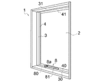
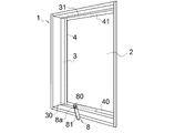
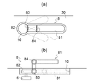
図1〜図2、図5に示す実施例1の開閉窓となるサッシ1は、窓の開口部に固定される正方形または長方形のサッシ枠3と、該サッシ枠3に沿って窓ガラス2を囲む障子枠(框)4を取付け、該障子枠4を、サッシ枠3との間に連結されたリンク機構5を介して開閉する構造を有している。
本実施例では、障子枠4の自由端側をサッシ枠3から離間させて障子枠4を開くリンク機構5と、該リンク機構5を操作ハンドル8に連結され操作ハンドル8の操作で開方向に変位させる作動アーム6とを有しており、図示例ではサッシは障子枠4の下枠40が室内側から室外側へ開くすべり出し窓の構造からなっている。
First, a description will be given of a structure in which an operation handle storage portion is provided in a window frame of a sash (hereinafter, referred to as a sash frame).
A sash 1 serving as an opening / closing window according to the first embodiment shown in FIGS. 1 to 2 and 5 includes a square or rectangular
In the present embodiment, a
この発明では、サッシの開閉は、図示例に限定されず、縦すべり出し窓、外倒し窓、内倒し窓、上げ下げ窓、オーニング窓、ルーバー窓などの開閉するサッシ窓など公知のサッシ窓枠構造が含まれる。 In the present invention, the opening and closing of the sash is not limited to the illustrated example. included.
前記サッシ1は、窓の開口部に固定される四角枠状のサッシ枠3と、サッシ枠3に開閉自在に取り付けられて窓ガラス2の四周を囲んで窓ガラス2を支持する障子枠4とからなっており、サッシ枠3またはサッシ枠3に一体に固定された基台部3’に窓開閉用の操作ハンドル8を設けた構造となっている。
図示例のすべり出し窓の場合は、サッシ枠3の下枠30上に操作ハンドル8が取り付けられている。
The sash 1 includes a square frame-shaped
In the case of the sliding window in the illustrated example, the
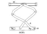
一方、サッシの障子枠4は、開閉側の枠(下枠40)に先端が枢着され、基端がサッシ枠の下枠30に枢着される開閉用のリンク機構5と、該リンク機構5に一端が枢着されて作動させる作動アーム6とからなり、該作動アーム6の基端には、ボルト型回転軸61が一体に設けられている。
このボルト型回転軸61は操作ハンドル8によって回転される。
On the other hand, the
The bolt
操作ハンドル8は、ボルト型回転軸61に係合して回転軸61を回転させるラチェット機構80と、該ラチェット機構80を操作するハンドル81とからなっており、ハンドル81の回転でボルト型回転軸61をサッシを開く正転方向または閉じる逆転方向に回転することができるようになっている(図5参照)。
The
前記リンク機構5は、図示例の場合、基端がサッシ枠の下枠30に枢着され、先端が障子枠4の下枠40に枢着されている。
そして、作動アーム6は、先端がリンク機構5に枢着され、基端は前記ボルト型回転軸61を介して操作ハンドル8に連動可能に連結されている。
従って、リンク機構5は、操作ハンドル8によって枢動する作動アーム6の変位によって、リンク機構5をサッシを開閉する方向に伸張または短縮させて前記障子枠4の下枠40を室外方向または室内方向に向かって平行移動させる。
In the illustrated example, the
The
Accordingly, the
サッシ枠3の下枠30には、作動アーム6の基端が枢着されており、該枢軸が前記ボルト型回転軸61となっている。
図示例では、上記ボルト型回転軸61は、上向きに略垂直に伸びている。
本実施例では、障子枠4の上枠41がサッシ枠3の上枠31に枢着され、障子枠4の上枠40が自由端となる構造からなるが、逆に障子枠4の上枠41側が開く場合には、障子枠4の下枠40がサッシ枠3の下枠30に枢着され、障子枠4の上枠41が自由端となり、リンク機構5はサッシ枠3の上枠31と障子枠4の上枠41との間に介設される(図示せず)。
The base end of the
In the illustrated example, the bolt-
In the present embodiment, the
この場合、操作ハンドル8は、サッシ枠3の上枠31に逆向きに装着してもよいが、サッシ枠3の下枠30や左右いずれかの側枠に装着し、作動アーム6との間に介設されて操作ハンドル8の動きを作動アーム6に向きを変えて伝動する中継リンク(図示省略)を設けてもよい。
また、リンク機構5は、サッシ枠3に対する障子枠4の開閉方向に対応するものであればよく、平行リンク機構に限らず、右または左へドア式に枢動するリンク機構であってもよい。
In this case, the operation handle 8 may be mounted on the
Further, the
また、リンク機構5と操作ハンドル8の位置は、同一レベルに配置されなくてもよく、向きや高さが異なる場合には、前述のように、作動アーム6と操作ハンドル8の間に操作ハンドル8の動きを作動アーム6ないしリンク機構5に高さや向きを変えて伝動する中継リンクを介設してもよい。
前記作動アーム6の先端は、リンク機構5に連動可能に連結されるが、図示例では、所定のリンク部材5’の中途位置に形成された長孔51に沿って摺動自在に枢着されている。
Further, the positions of the
The distal end of the
このようにこの発明でリンク機構と作動アームの枢着は、長孔内で移動しながら枢着される場合を含んでいる。
そして、上記リンク部材5’の先端は、サッシ4の障子枠4に固定された長孔を有する連結金具45の長孔46にスライド可能に枢着されている。
これにより、作動アーム6のボルト型回転軸61を基点にした枢動は、枢動変位するリンク部材5’を介して障子枠4の下枠40を平行移動させることができる。
As described above, the pivotal connection between the link mechanism and the operating arm in the present invention includes a case where the linking mechanism and the operating arm are pivotally connected while moving in the elongated hole.
The distal end of the link member 5 'is pivotally slidably connected to a
Thus, the pivotal movement of the
図6に示すリンク機構5は、作動アーム6と中途位置で交差するパンタグラフ形状となっている。
この場合も前記実施例と同様に作動アーム6のボルト型回転軸61を基点にした枢動は、リンク機構5を介してサッシ4の可動枠41を平行移動させることができる。
この発明のリンク機構5は、サッシ4の障子枠4の自由端側を平行移動または枢動により窓を開閉する方向に変位することができればよく、公知の1または複数のリンク部材を用いたリンク機構を用いることができる。
The
In this case, similarly to the above-described embodiment, the pivotal movement of the
The
本実施例で、操作ハンドル8は、前述のように、ボルト型回転軸61を操作する一種のラチェットハンドル構造からなっている。
操作ハンドル8は、前記作動アーム6のボルト型回転軸61と噛合する係合受部と一体のドライブギアとを有しており。該ドライブギアはクロウ(爪部)によって1個所または2個所で支持されており、ドライブギアの回転方向が一方向に拘束され逆進できない公知構成からなっているので説明を省略する。
ラチェット機構80の一例を示せば、実開平6−666号公報、特開2002−307318号公報などの公知構造が知られている。
In this embodiment, the operation handle 8 has a ratchet handle structure for operating the bolt-
The operation handle 8 has a drive gear integrated with an engagement receiving portion that meshes with the bolt-
As an example of the
また、操作ハンドル8には、逆進ロック方向を切り替える公知のクロウを切り替える切替レバー8aが設けられており、該切替レバー8aを切り替えることで、前記クロウのロックの向きを変え、ドライブギアの回転方向を正転方向および逆転方向に切り替えて回転させることができる。
ここで、操作ハンドル8は、前述のように作動アーム6のボルト型回転軸61の回転方向に対応して回転するように、操作ハンドル8の係合受部およびドライブギアが配置されている。
The operation handle 8 is provided with a known
Here, the engagement receiving portion of the
上記構成からなっているので、使用者は、操作ハンドル8を前記ボルト型回転軸61を中心に水平方向に回転させることで、作動アーム6を介してリンク機構5を変位させてサッシの障子枠4の下枠40を室外方向に横滑りさせてサッシを開くことができる(図2参照)。
このように、リンク機構5は、サッシ窓の開く方向に対して伸縮するリンク機構または枢動するリンク機構5であり、先端は障子枠4の開く(自由端となる)側の枠に枢着され、作動アーム6は上記リンク機構5を開閉方向に変位するように枢動し、該作動アーム6の基端の枢軸となるボルト型回転軸61に直接にまたは中継する伝動リンクを介して操作ハンドル8が連結される。
With the above configuration, the user rotates the operation handle 8 in the horizontal direction about the bolt-
As described above, the
前記操作ハンドル8は、ボルト型回転軸61に係合する側がラチェット機構80となっているので、ハンドル81側を360度回転させる必要がない。
即ち、操作ハンドル8は任意の角度だけ部分的にサッシを開く方向に回転させることができる。
Since the operation handle 8 has a
That is, the operation handle 8 can be partially rotated by an arbitrary angle in a direction to open the sash.
そして、操作ハンドル8はラチェット機構80からなるので、ハンドル81の回転方向とは逆方向の回転は前記回転軸61に伝わらず、ロックされているので、ハンドルをまた戻して同じ方向に回転させればよいので、操作ハンドルの回転角度は360度とすることなく、任意の角度ですみ、サッシ回りの造作物と操作ハンドル8とが干渉することなく、サッシを開くことがきる。
Since the operation handle 8 is composed of the
同様に、操作ハンドル8の回転方向の切替レバー8aを切り替えて、ハンドル81を逆転方向に回転することで、今度はサッシを閉じる逆方向に回転させることができ、作動アーム6は逆方向に枢動してサッシの障子枠を元の位置に戻して窓を閉じることができる。
Similarly, by switching the switching
この発明では更に、窓を閉じたり、開いた入りして状態を維持するような操作ハンドル8を使用しない場合には、そのままの姿勢で、操作ハンドル8を、サッシ枠3や基台部30’などのハンドル8を配置した個所に凹状の操作ハンドル収納部10を設け、該操作ハンドル収納部10に没入させることができる。
Further, in the present invention, when the operation handle 8 that keeps the state by closing or opening the window is not used, the operation handle 8 is held in the posture as it is, and the
該操作ハンドル収納部10は、操作ハンドル8全体を完全に没入できる凹部からなっている。
即ち、図示例では、サッシ枠3の下枠30上に、操作ハンドル8が、障子枠4の下枠40と平行の向きとなるように前記下枠30に前記操作ハンドル収納部10が形成されている(図3、図4参照)。
The operation
That is, in the illustrated example, the operation
即ち、サッシ枠3の下枠30には、使用時には下枠30上に突出し、不使用時には操作ハンドル収納部10内に没入させることができるように操作ハンドル8が設置されている。
前記操作ハンドル収納部10の上面には操作ハンドル収納部10の開口を塞ぐ方向に付勢されたカバー(図示省略)を設けてもよい。
このカバーは、操作ハンドルを押し込む際にハンドルの下降によって内側に折れ曲がって操作ハンドル収納部10の開口を空け、ハンドルの上昇によって付勢力で復帰し操作ハンドル収納部10の開口を塞ぐ構成でよい。
そして、作動アーム6のボルト型回転軸61または操作ハンドル8には上下に昇降する出没機構が設けられていることが好ましい。
That is, the
A cover (not shown) may be provided on the upper surface of the operation
This cover may be configured to bend inward by lowering the handle when the operation handle is pushed in to open the opening of the operation
The bolt-
出没機構は、前記回転軸61は操作ハンドル収納部10の下方に配置されており、操作ハンドル8だけが上下に摺動して出没する構造、回転軸61と操作ハンドル8が共に上下に摺動して出没する構造など、要するに回転軸61も操作ハンドル8も操作ハンドル収納部10の上には突出しない構造などであればよい。
The retracting mechanism has a structure in which the
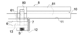
例えば、図7に一例を示すように、前記作動アーム6およびこれに固定された回転軸61を上下方向に摺動可能とすると共に、操作ハンドル8の使用位置を上限とする拘束部材7を設けて上向きに付勢手段Sで付勢して取付けてある。
図示例では、操作ハンドル収納部10が、操作ハンドル8のハンドル部分を収納する操作ハンドル収納部本体11と、該操作ハンドル収納部本体11の先端に連設されて段違い状に深くなる付勢収納部12とからなっている。
For example, as shown in FIG. 7, an
In the illustrated example, the operation
該付勢収納部12は、作動アーム6や回転軸61を昇降可能に収納し、その下方に、上端が前記作動アーム6又は回転軸61に掛け止められ、下端がに付勢収納部12の底部に固定された付勢手段Sが収納されている。
なお、作動アーム6の摺動が規制されないように付勢収納部12の一側には開口13が形成されている。
この場合には、操作ハンドル8を実線で示す使用位置から押し下げることで、作動アーム6も連動して下降し、操作ハンドル8を操作ハンドル収納部10の収納部本体11の凹部に収納することができる。
The urging
An
In this case, when the
図8では、作動アーム6の位置(高さ)は変わらず、ボルト型回転軸61と操作ハンドル8が一体的に上下に摺動する構造としている。
この場合、回転軸61は操作ハンドル収納部10の先端の付勢収納部12に配置されておりスプリングなどの付勢手段Sで上向きに付勢されている。
In FIG. 8, the position (height) of the
In this case, the rotating
操作ハンドル8は、回転軸61によって使用位置方向に付勢される。
上記回転軸61は断面が多角形の軸からなっており、作動アーム6は回転軸61との連結部分を回転軸61の断面多角形と整合する多角形の孔として、回転軸61だけを上下に摺動可能とし、回転軸61の回転方向にのみ連動しする構成となっている。
また、図示例では、前記回転軸61の下方に掛止部62が形成されており、付勢収納部12の底部に設けられたスプリングSの上端が前記掛止部に掛止められて回転軸61を上方に付勢している。
操作ハンドル8の出没構造は、その他、公知の出没構造を用いてもよい。
The operation handle 8 is urged by the
The
In the illustrated example, a
As the projecting structure of the
なお、操作ハンドル収納部10に収納された操作ハンドル8を収納位置に保持するための係脱可能な保持手段9を操作ハンドル収納部10の周壁に設けることが好ましい。
図9で例示する保持手段9は、一方が、操作ハンドル収納部10の側壁にプランジャ91を埋設し、先端のボール92だけが僅かに突出する構成を有しており、他方が、操作ハンドル8の操作ハンドル収納部10への収納時に前記ボール92と整合する位置に、前記ボール92を係合する略半球状の凹部93からなっている。
It is preferable that a detachable holding means 9 for holding the operation handle 8 stored in the operation
One of the holding means 9 illustrated in FIG. 9 has a configuration in which one side has a
これにより、操作ハンドル8を操作ハンドル収納部10に押し込むと、前記プランジャ91のボール92が下降するハンドル8の外周面によって操作ハンドル収納部10の奥側に押し込まれ、前記ハンドル8の凹部93と整合すると付勢力で凹部93内に突入して係合するので、操作ハンドル8への上向きの付勢力が抑えられてハンドル8が上昇しないようにロックされる。
Thus, when the
ハンドル8使用時には、前記操作ハンドル8をプランジャ91の付勢力に抗して強く上向きに引っ張ることで、前記ボール92は凹部93から押し出されてロックが解除され、操作ハンドル8は図示しない付勢手段の上方への付勢力によって使用位置まで上昇する。
あるいは、収納部本体11の底面をハンドル8の収納位置より更に下方に離間させておくことで、収納位置のハンドル8を強く下に押し込むことで前記保持手段9のロックから外し、付勢手段Sの付勢力を高めて、その反発力で使用位置に自動的に戻すなどの構造でもよい。
When the
Alternatively, the bottom surface of the storage unit
前記ハンドル8を手動で上向きに引っ張る場合には、ハンドル8の上部に摘みまたは把手Hを設けてもよい。
保持手段9には、プランジャのボールと半球状の凹部との組合せに限らず、操作ハンドル収納部10内に設けられて、ハンドル8の下降時にハンドル8の上昇を拘束する拘束方向に付勢された拘束バー、その他の公知の手段を用いることができる。
When the
The holding means 9 is provided not only in the combination of the ball of the plunger and the hemispherical concave portion but also in the operation
なお、回転軸61と操作ハンドル8の係合受部には、係合受部が所定位置以上に上昇しないように拘束する拘束手段7を設けておけば、操作ハンドル8が付勢力で上昇する際に、所定位置で操作ハンドルの上昇を拘束することができる。
例えば、係合受部の下端が回転軸61の下部に係合する凸部を有する構造などを設けておけばよい。
If the engaging portion between the
For example, a structure having a convex portion in which the lower end of the engagement receiving portion is engaged with the lower portion of the
上記実施例では、開閉リンク機構5と作動アーム6を別体としたが、作動アーム6が開閉リンク機構5を兼ねるものであってもよいし、作動アーム6が開閉リンク機構5の一部を構成するものであってもよい。
その他この発明は、上記構造に限定されるものではなく、要するに、この発明の要旨を変更しない範囲で種々設計変更することができる。
In the above embodiment, the opening /
In addition, the present invention is not limited to the above-described structure, that is, various design changes can be made without changing the gist of the present invention.
次に、図10に異なる構造の操作ハンドル8について説明する。
この操作ハンドル8は、基本構造は前述のラチェット機構を内蔵したものであるが、グリップとなるハンドル81の構造が異なっている。
即ち、操作ハンドル収納部10内にはハンドル81を除き、操作ハンドル8のラチェット機能を有する主要部82は没入したままとなっている。
ここで上記主要部82は平面視略円形状となっていることが好ましい。
上記主要部82に対応する操作ハンドル収納部10とのクリアランスは、後述のようにハンドルを折り曲げた状態で主要部82が回転しうるクリアランスが設けられていればよい。
Next, an
The operation handle 8 has a basic structure in which the aforementioned ratchet mechanism is built in, but the structure of a
That is, the
Here, it is preferable that the
The clearance between the
また、前記ハンドル81は、操作ハンドル収納部10に設けられた弾性部材で上向きに付勢することが好ましく、その場合も、操作ハンドル収納部10の側面に前記付勢力に抗してハンドル81を操作ハンドル収納部10内に保持するストッパを設けることが好ましい。そこで、ハンドル81の後方を奥に押し込んでストッパを解除し、弾性部材の付勢力で操作ハンドル収納部10の上に押し上げるようにすることが好ましい。
Further, it is preferable that the
そして、操作時には、前記ハンドル81は、主要部82との間にヒンジ部を介するなどして、上方に折曲げ可能となっており、ハンドル81だけが前記収納部10から突出する。
図示例では、前記ヒンジ部を2個所設けておき、主要部82から第1関節部83を直角に折り曲げ、第2関節部84を水平に折り曲げる。
図示例では、各関節部は90°折れ曲がる構造となっているが、この発明では操作しやすい任意の角度に折れ曲がるようにしてもよい。
During operation, the
In the illustrated example, two hinge portions are provided, the first
In the illustrated example, each joint is bent at 90 °. However, in the present invention, the joint may be bent at an arbitrary angle that is easy to operate.
これにより第2関節部84より後方のハンドルを回して操作することができる。
この実施例では、関節部は1個所だけでもよいし2個所以上の複数個所でもよい。
上記構成の場合、主要部82と作動アーム6とは、昇降させる必要がなく、一定位置に維持した状態で操作できるので便利である。
Thus, the steering wheel behind the second joint 84 can be operated.
In this embodiment, the number of joints may be one, or two or more.
In the case of the above configuration, the
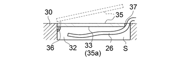
次に、網戸20について説明する。
図11に示すように、本実施例では、サッシ枠3の下枠30で、障子枠4のレールより内側(室内側)に網戸20を固定するための取付溝25が設けられている。
前記網戸20は、ネット状の網本体21の周縁にゴムまたはエラストマーのシール材からなる弾性縁部22を固定した構造からなっている。
Next, the
As shown in FIG. 11, in the present embodiment, a mounting groove 25 for fixing the
The
この網戸20は、弾性縁部22を前記網戸用の取付溝25に圧縮した状態で嵌合して固定される。
該網戸20の弾性縁部22の室内側の面には、リボン状の網戸取外し片26の基端が接着されている。
この網戸取外し片26は、前記取付溝25からサッシ枠3(図示例では下枠30)上に突出するので、網戸20を取り外す際には、上記網戸取外し片26を引っ張ることで、前記弾性縁部22の1部を取付溝25から外すことができ、そこをきっかけとして網戸20の全周の弾性縁部22を外して網戸20を取り外すことができる。
The
A proximal end of a ribbon-shaped screen
Since the screen
上記網戸取外し片26がサッシ枠3上に表出していると、網戸取外し片26が損傷や破断するおそれがあり、また美観上も好ましくない。
そこで、この発明では、サッシ枠3の下枠30に網戸取外し片26を収納する取外し片収納部32が形成される。
If the screen
Therefore, in the present invention, a removal
この取外し片収納部32は、下枠30に網戸取外し片26の突出部分を収納する空間Sを有しており、該空間Sの上部には閉じた際に下枠30と同一面となる開閉自在な外蓋片35を有している。
即ち、外蓋片35は、下枠30に連結する可撓性または弾性を有する連結片36を介して分離しないように繋がっており、下枠30の前記空間Sの開口縁部に形成された係合段部33に外蓋片35の外周縁部35aが係合するようになっている(図12参照)。
The detachable
That is, the
図示例では係合段部33は蟻溝状となっており、外蓋片35を強く押し込むことで、外蓋片35が係合段部33に掛止められる。
外蓋片35を開く場合は、外蓋片35を取外し片収納部32の上面の隙間37から押し上げて開いて、収納されている網戸取外し片26を使用することができる。
上記外蓋片36の取外し片収納部32への係合や、連結部は公知の構造に置き換えてよい。
In the illustrated example, the engaging
When the
The engagement of the
そこで、網戸取外し片26の突出部分を前記空間Sに収納し、外蓋片35を係合段部33に係合することで、下枠30上面をフラットに整えることができる。前記空間Sは有底であっても無底であってもよい。
本実施例では、取外し片収納部32はサッシ枠3の下枠30に配置した例を示したが、左右のサッシ枠のいずれか一方に設けるものでもよい。
Then, the projecting portion of the screen
In the present embodiment, an example is shown in which the detachable
これによりサッシ枠に、網戸の取外し片収納部と操作ハンドル収納部とを設ける場合でもサッシ枠はフラットとなり、サッシ枠上も整理され、サッシの美観を向上させることができる。
その他、要するにこの発明は上記実施例に限定されるものではなく、その要旨を変更しない範囲で種々設計変更しうること勿論である。
Thus, even when the sash frame is provided with the detachable piece storage portion and the operation handle storage portion of the screen door, the sash frame is flat, and the sash frame is also arranged, so that the appearance of the sash can be improved.
In other words, the present invention is not limited to the above-described embodiment, and it goes without saying that various design changes can be made without changing the gist of the present invention.
1 開閉窓
2 窓ガラス
3 サッシ枠(窓枠)
4 障子枠(框)
5 リンク機構
6 作動アーム
7 拘束部材
8 操作ハンドル
8a 切替レバー
9 保持手段
10 収納部
20 網戸
21 網本体
22 弾性縁部
25 網戸の取付溝
26 網戸取外し片
30 サッシ枠の下枠
30’サッシ枠に固定される基台部
31 上枠
32 取外し片収納部
33 係合段部
35 外蓋片
35a 外周縁部
36 連結片
s 40 障子枠の下枠
61 ボルト型回転軸
80 ラチェット機構
81 ハンドル
82 主要部
83 第1関節部
84 第2関節部
1
4 Shoji frame (frame)
DESCRIPTION OF
Claims (4)
網戸が、網本体の周縁に弾性縁部を有して網戸の取付溝に嵌合しており、
該網戸の弾性縁部の室内側の面に網戸取外し片を設けて窓枠側に突出させており、
窓枠には、閉じた際に窓枠と同一面となる開閉自在な外蓋片を有し、前記網戸取外し片を窓枠の内部に収納する取外し片収納部が設けられると共に、
前記操作ハンドルには、前記リンク機構を作動させる作動アームに設けられたボルト型回転軸に嵌合し、切替部の操作で回転方向を正転方向または逆転方向に切替可能に回転させるラチェット機能と、該ラチェット機構を回転させるハンドル部とを有しており、
前記窓枠には、操作ハンドルの不使用時に少なくとも操作ハンドルの上面が障子枠と同一面となる収納用の凹部または収納時に上面開口を塞いで上面が窓枠と同一面となる外蓋部を有する操作ハンドル収納部が形成されてなることを特徴とするサッシ窓枠構造。 By rotating the operation handle, the operation arm is pivoted, and the frame is pivoted in the opening and closing direction via a link mechanism connected between the window frame and the frame of the sash, and the window frame is moved to the room side from the frame with the window frame. In the sash window frame structure with the mounting groove,
The screen door has an elastic edge on the periphery of the net body and is fitted into the mounting groove of the screen door,
A screen door removal piece is provided on the indoor side surface of the elastic edge of the screen door, and is projected toward the window frame side,
The window frame has an openable and closable outer lid piece that is flush with the window frame when closed, and a detachable piece storage portion for storing the screen door remover inside the window frame is provided.
The operation handle has a ratchet function that is fitted to a bolt-type rotation shaft provided on an operation arm that operates the link mechanism, and that rotates the rotation direction so that the rotation direction can be switched to a normal rotation direction or a reverse rotation direction by operating a switching unit. , A handle portion for rotating the ratchet mechanism,
In the window frame, when the operation handle is not used, at least the upper surface of the operation handle is flush with the shoji frame, or a storage recess or an outer lid portion whose upper surface is flush with the window frame by closing the upper surface opening during storage. A sash window frame structure characterized by comprising an operation handle storage portion having the same.
Priority Applications (1)
| Application Number | Priority Date | Filing Date | Title |
|---|---|---|---|
| JP2018129547A JP7057725B2 (en) | 2018-07-06 | 2018-07-06 | Sash window frame structure |
Applications Claiming Priority (1)
| Application Number | Priority Date | Filing Date | Title |
|---|---|---|---|
| JP2018129547A JP7057725B2 (en) | 2018-07-06 | 2018-07-06 | Sash window frame structure |
Publications (2)
| Publication Number | Publication Date |
|---|---|
| JP2020007782A true JP2020007782A (en) | 2020-01-16 |
| JP7057725B2 JP7057725B2 (en) | 2022-04-20 |
Family
ID=69151113
Family Applications (1)
| Application Number | Title | Priority Date | Filing Date |
|---|---|---|---|
| JP2018129547A Active JP7057725B2 (en) | 2018-07-06 | 2018-07-06 | Sash window frame structure |
Country Status (1)
| Country | Link |
|---|---|
| JP (1) | JP7057725B2 (en) |
Families Citing this family (1)
| Publication number | Priority date | Publication date | Assignee | Title |
|---|---|---|---|---|
| JP7412701B2 (en) | 2020-01-28 | 2024-01-15 | 日本ゼオン株式会社 | Electrodes for secondary batteries |
Citations (4)
| Publication number | Priority date | Publication date | Assignee | Title |
|---|---|---|---|---|
| JPS61107876U (en) * | 1984-12-20 | 1986-07-08 | ||
| JP2008075420A (en) * | 2006-09-25 | 2008-04-03 | Tostem Corp | Opening device provided with opening/closing means |
| JP2010242333A (en) * | 2009-04-02 | 2010-10-28 | Miwa Lock Co Ltd | Handle device |
| JP2017057691A (en) * | 2015-09-18 | 2017-03-23 | Ykk Ap株式会社 | Net body for fitting, and fitting |
-
2018
- 2018-07-06 JP JP2018129547A patent/JP7057725B2/en active Active
Patent Citations (4)
| Publication number | Priority date | Publication date | Assignee | Title |
|---|---|---|---|---|
| JPS61107876U (en) * | 1984-12-20 | 1986-07-08 | ||
| JP2008075420A (en) * | 2006-09-25 | 2008-04-03 | Tostem Corp | Opening device provided with opening/closing means |
| JP2010242333A (en) * | 2009-04-02 | 2010-10-28 | Miwa Lock Co Ltd | Handle device |
| JP2017057691A (en) * | 2015-09-18 | 2017-03-23 | Ykk Ap株式会社 | Net body for fitting, and fitting |
Also Published As
| Publication number | Publication date |
|---|---|
| JP7057725B2 (en) | 2022-04-20 |
Similar Documents
| Publication | Publication Date | Title |
|---|---|---|
| JP2008254667A (en) | Lid opening/closing device | |
| JP2005178674A (en) | Overhead console device | |
| JP2007269318A (en) | Open roof structure body for vehicle and vehicle mounted with such open roof structure body | |
| JP5262689B2 (en) | Door opening / closing structure and door opening / closing device | |
| KR101382759B1 (en) | Liner type center rail link structure of sliding door for vehicle | |
| JPH04237783A (en) | Right and left opening device for console box of automobile and the like | |
| JP2020007782A (en) | Sash window frame structure | |
| KR101407021B1 (en) | Door stopper | |
| JP6701103B2 (en) | Window opening/closing device handle structure | |
| CN109972938B (en) | Mechanism for opening vehicle door | |
| JP4970016B2 (en) | Lid opening / closing structure | |
| JP5003201B2 (en) | Outside door handle | |
| JP2008062694A (en) | Container holder apparatus | |
| JP4511843B2 (en) | Emergency escape door locking device | |
| JP4765129B2 (en) | Window opening and closing device | |
| JP2005104173A (en) | Arm rest device | |
| JP4974146B2 (en) | Compact container | |
| JP2010208442A (en) | Driving device of moving body | |
| KR101249150B1 (en) | Locking section assembly of digital locking device for window | |
| KR101172138B1 (en) | Structure of console arm rest | |
| KR20110112546A (en) | A opening and closing apparatus of the door | |
| JP2006504008A (en) | Car door handle | |
| JP6461669B2 (en) | Swing window lock operation device | |
| JP2006281879A (en) | Position keeping mechanism of vehicular opening/closing body | |
| JP4158979B2 (en) | Latch device and inward window using the latch device |
Legal Events
| Date | Code | Title | Description |
|---|---|---|---|
| A621 | Written request for application examination |
Free format text: JAPANESE INTERMEDIATE CODE: A621 Effective date: 20210625 |
|
| A977 | Report on retrieval |
Free format text: JAPANESE INTERMEDIATE CODE: A971007 Effective date: 20220308 |
|
| TRDD | Decision of grant or rejection written | ||
| A01 | Written decision to grant a patent or to grant a registration (utility model) |
Free format text: JAPANESE INTERMEDIATE CODE: A01 Effective date: 20220323 |
|
| A61 | First payment of annual fees (during grant procedure) |
Free format text: JAPANESE INTERMEDIATE CODE: A61 Effective date: 20220408 |
|
| R150 | Certificate of patent or registration of utility model |
Ref document number: 7057725 Country of ref document: JP Free format text: JAPANESE INTERMEDIATE CODE: R150 |