JP2020006834A - Control data creation apparatus, component control apparatus, control data creation method, component control method, and computer program - Google Patents
Control data creation apparatus, component control apparatus, control data creation method, component control method, and computer program Download PDFInfo
- Publication number
- JP2020006834A JP2020006834A JP2018130244A JP2018130244A JP2020006834A JP 2020006834 A JP2020006834 A JP 2020006834A JP 2018130244 A JP2018130244 A JP 2018130244A JP 2018130244 A JP2018130244 A JP 2018130244A JP 2020006834 A JP2020006834 A JP 2020006834A
- Authority
- JP
- Japan
- Prior art keywords
- control
- evaluation
- unit
- output
- learning model
- Prior art date
- Legal status (The legal status is an assumption and is not a legal conclusion. Google has not performed a legal analysis and makes no representation as to the accuracy of the status listed.)
- Granted
Links
Images


Classifications
-
- B—PERFORMING OPERATIONS; TRANSPORTING
- B62—LAND VEHICLES FOR TRAVELLING OTHERWISE THAN ON RAILS
- B62M—RIDER PROPULSION OF WHEELED VEHICLES OR SLEDGES; POWERED PROPULSION OF SLEDGES OR SINGLE-TRACK CYCLES; TRANSMISSIONS SPECIALLY ADAPTED FOR SUCH VEHICLES
- B62M6/00—Rider propulsion of wheeled vehicles with additional source of power, e.g. combustion engine or electric motor
- B62M6/40—Rider propelled cycles with auxiliary electric motor
- B62M6/45—Control or actuating devices therefor
- B62M6/50—Control or actuating devices therefor characterised by detectors or sensors, or arrangement thereof
-
- B—PERFORMING OPERATIONS; TRANSPORTING
- B62—LAND VEHICLES FOR TRAVELLING OTHERWISE THAN ON RAILS
- B62J—CYCLE SADDLES OR SEATS; AUXILIARY DEVICES OR ACCESSORIES SPECIALLY ADAPTED TO CYCLES AND NOT OTHERWISE PROVIDED FOR, e.g. ARTICLE CARRIERS OR CYCLE PROTECTORS
- B62J45/00—Electrical equipment arrangements specially adapted for use as accessories on cycles, not otherwise provided for
- B62J45/20—Cycle computers as cycle accessories
-
- B—PERFORMING OPERATIONS; TRANSPORTING
- B62—LAND VEHICLES FOR TRAVELLING OTHERWISE THAN ON RAILS
- B62J—CYCLE SADDLES OR SEATS; AUXILIARY DEVICES OR ACCESSORIES SPECIALLY ADAPTED TO CYCLES AND NOT OTHERWISE PROVIDED FOR, e.g. ARTICLE CARRIERS OR CYCLE PROTECTORS
- B62J50/00—Arrangements specially adapted for use on cycles not provided for in main groups B62J1/00 - B62J45/00
- B62J50/20—Information-providing devices
- B62J50/21—Information-providing devices intended to provide information to rider or passenger
- B62J50/22—Information-providing devices intended to provide information to rider or passenger electronic, e.g. displays
-
- G—PHYSICS
- G06—COMPUTING; CALCULATING OR COUNTING
- G06N—COMPUTING ARRANGEMENTS BASED ON SPECIFIC COMPUTATIONAL MODELS
- G06N20/00—Machine learning
-
- G—PHYSICS
- G06—COMPUTING; CALCULATING OR COUNTING
- G06N—COMPUTING ARRANGEMENTS BASED ON SPECIFIC COMPUTATIONAL MODELS
- G06N3/00—Computing arrangements based on biological models
- G06N3/02—Neural networks
- G06N3/08—Learning methods
-
- G—PHYSICS
- G06—COMPUTING; CALCULATING OR COUNTING
- G06V—IMAGE OR VIDEO RECOGNITION OR UNDERSTANDING
- G06V40/00—Recognition of biometric, human-related or animal-related patterns in image or video data
- G06V40/10—Human or animal bodies, e.g. vehicle occupants or pedestrians; Body parts, e.g. hands
- G06V40/16—Human faces, e.g. facial parts, sketches or expressions
- G06V40/174—Facial expression recognition
- G06V40/175—Static expression
-
- G—PHYSICS
- G06—COMPUTING; CALCULATING OR COUNTING
- G06V—IMAGE OR VIDEO RECOGNITION OR UNDERSTANDING
- G06V20/00—Scenes; Scene-specific elements
- G06V20/40—Scenes; Scene-specific elements in video content
-
- G—PHYSICS
- G06—COMPUTING; CALCULATING OR COUNTING
- G06V—IMAGE OR VIDEO RECOGNITION OR UNDERSTANDING
- G06V20/00—Scenes; Scene-specific elements
- G06V20/50—Context or environment of the image
- G06V20/56—Context or environment of the image exterior to a vehicle by using sensors mounted on the vehicle
Landscapes
- Engineering & Computer Science (AREA)
- Theoretical Computer Science (AREA)
- Physics & Mathematics (AREA)
- Mechanical Engineering (AREA)
- General Physics & Mathematics (AREA)
- Chemical & Material Sciences (AREA)
- Combustion & Propulsion (AREA)
- Software Systems (AREA)
- Health & Medical Sciences (AREA)
- General Health & Medical Sciences (AREA)
- Mathematical Physics (AREA)
- Computing Systems (AREA)
- General Engineering & Computer Science (AREA)
- Artificial Intelligence (AREA)
- Evolutionary Computation (AREA)
- Data Mining & Analysis (AREA)
- Oral & Maxillofacial Surgery (AREA)
- Multimedia (AREA)
- Human Computer Interaction (AREA)
- Transportation (AREA)
- Medical Informatics (AREA)
- Computer Vision & Pattern Recognition (AREA)
- Life Sciences & Earth Sciences (AREA)
- Biomedical Technology (AREA)
- Biophysics (AREA)
- Computational Linguistics (AREA)
- Molecular Biology (AREA)
- Control Of Driving Devices And Active Controlling Of Vehicle (AREA)
- Feedback Control In General (AREA)
Abstract
Description
本発明は、人力駆動車のコンポーネントの制御に関するデータの制御データ作成装置、コンポーネント制御装置、制御データ作成方法、コンポーネント制御方法、およびコンピュータプログラムに関する。 The present invention relates to a control data creation device for data related to control of components of a manually driven vehicle, a component control device, a control data creation method, a component control method, and a computer program.
自転車をはじめとして電動アシスト付き自転車、Eバイクと呼ばれる電動自転車等、少なくとも部分的に人力が用いられる人力駆動車がある。人力駆動車は、複数の段数を持つ変速機を備え、乗り手の変速操作に応じて段数が切り替えられる。速度センサ、ケイデンスセンサ、チェーンテンションセンサ等のセンサを用い、センサからの出力に対して種々の演算を行なって自動的に変速制御する自動変速制御システムが従来提案されている(特許文献1等)。
There are man-powered vehicles at least partially using human power, such as bicycles, bicycles with electric assist, electric bicycles called E-bikes, and the like. The human-powered vehicle includes a transmission having a plurality of gear stages, and the number of gear stages is switched according to a shift operation of a rider. 2. Description of the Related Art An automatic shift control system that uses a sensor such as a speed sensor, a cadence sensor, or a chain tension sensor, performs various calculations on the output from the sensor, and performs automatic shift control has been proposed (
自動変速制御の目指すものは、乗り手の意図に合った変速である。特許文献1等に開示されている変速機を含むコンポーネントの自動制御は、人力駆動車に設けられた速度センサ、トルクセンサ等の各種センサから得られる数値が所定の閾値より大きいか否かの判断の組み合わせにより実現されてきた。しかしながら、閾値による判断では目指す自動制御の実現には不足であった。
The purpose of the automatic shift control is a shift that meets the rider's intention. The automatic control of components including a transmission disclosed in
本発明の目的は、乗り手に違和感を生じさせにくいコンポーネントの自動制御を実現する情報の制御データ作成装置、コンポーネント制御装置、制御データ作成方法、コンポーネント制御方法、およびコンピュータプログラムを提供することである。 An object of the present invention is to provide an information control data creation device, a component control device, a control data creation method, a component control method, and a computer program that realize automatic control of components that are unlikely to cause discomfort to a rider.
(1)本発明の第1側面に従う制御データ作成装置は、人力駆動車の走行に関する入力情報を取得する取得部と、前記取得部が取得した入力情報に基づいて前記人力駆動車のコンポーネントの制御に関する出力情報を出力する、学習モデルを学習アルゴリズムによって作成する作成部と、前記学習モデルから出力された出力情報を評価する評価部とを備え、前記作成部は、前記評価部の評価と、前記出力情報の出力に対応する入力情報と、前記出力情報とを含む教師データに基づいて前記学習モデルを更新する。
このため、走行に関する測定値を含む多数の入力情報に基づき、閾値では判定しきれない状況に応じたコンポーネント制御をより最適化させることができ、乗り手に違和感を生じさせにくい制御が実現できる。
(1) A control data creation device according to a first aspect of the present invention includes: an acquisition unit configured to acquire input information on traveling of a manually driven vehicle; and control of components of the manually driven vehicle based on the input information acquired by the acquisition unit. Outputting output information related to, including a creating unit that creates a learning model by a learning algorithm, and an evaluation unit that evaluates output information output from the learning model, wherein the creating unit evaluates the evaluation unit, The learning model is updated based on teacher data including input information corresponding to output of output information and the output information.
For this reason, based on a large number of input information including measured values relating to traveling, component control according to a situation that cannot be determined with a threshold value can be further optimized, and control that does not cause a discomfort to the rider can be realized.
(2)本発明の第2側面に従う制御データ作成装置は、上記第1側面の制御データ作成装置において、前記評価部は、前記学習モデルから出力された出力情報によるコンポーネントの制御がスムーズであったか否かを判断し、スムーズであった場合に評価を向上させる。
このため、スムーズとなるようにコンポーネント制御が最適化され、乗り手に違和感を生じさせにくい制御が実現できる。
(2) In the control data creation device according to the second aspect of the present invention, in the control data creation device according to the first aspect, the evaluation unit determines whether control of the component based on output information output from the learning model is smooth. Judge whether it is smooth and improve the evaluation.
For this reason, the component control is optimized so as to be smooth, and control that does not cause a sense of discomfort to the rider can be realized.
(3)本発明の第3側面に従う制御データ作成装置は、上記第2側面の制御データ作成装置において、前記評価部は、前記制御の際の前記人力駆動車の駆動機構に掛かるトルクを検知し、前記トルクに応じてスムーズであったか否かを判断する。
このため、乗り手に違和感を生じさせにくい制御が実現できる。
(3) In the control data creation device according to a third aspect of the present invention, in the control data creation device according to the second aspect, the evaluation unit detects a torque applied to a drive mechanism of the manually driven vehicle during the control. Then, it is determined whether or not the operation is smooth in accordance with the torque.
For this reason, it is possible to realize a control that does not cause the rider to feel uncomfortable.
(4)本発明の第4側面に従う制御データ作成装置は、上記第2側面の制御データ作成装置において、前記評価部は、前記制御の際の前記人力駆動車の駆動機構に掛かるトルクを検知し、前記トルクの変動に応じてスムーズであったか否かを判断する。
このため、乗り手に違和感を生じさせにくい制御が実現できる。
(4) In the control data creation device according to the fourth aspect of the present invention, in the control data creation device according to the second aspect, the evaluation unit detects a torque applied to a drive mechanism of the manually driven vehicle during the control. Then, it is determined whether or not the rotation is smooth in accordance with the fluctuation of the torque.
For this reason, it is possible to realize a control that does not cause the rider to feel uncomfortable.
(5)本発明の第5側面に従う制御データ作成装置は、上記第2側面の制御データ作成装置において、前記評価部は、前記制御の際の前記人力駆動車の姿勢を検知し、前記人力駆動車の姿勢に応じてスムーズであったか否かを判断する。
このため、乗り手に違和感を生じさせにくい制御が実現できる。
(5) In the control data creation device according to a fifth aspect of the present invention, in the control data creation device according to the second aspect, the evaluation unit detects a posture of the manually driven vehicle during the control, and It is determined whether or not the vehicle is smooth according to the posture of the vehicle.
For this reason, it is possible to realize a control that does not cause the rider to feel uncomfortable.
(6)本発明の第6側面に従う制御データ作成装置は、上記第2側面の制御データ作成装置において、前記評価部は、前記制御の際の前記人力駆動車の振動を検知し、前記振動に応じてスムーズであったか否かを判断する。
このため、乗り手に違和感を生じさせにくい制御が実現できる。
(6) The control data creation device according to a sixth aspect of the present invention is the control data creation device according to the second aspect, wherein the evaluation unit detects vibration of the manually driven vehicle during the control, and It is determined whether or not it was smooth.
For this reason, it is possible to realize a control that does not cause the rider to feel uncomfortable.
(7)本発明の第7側面に従う制御データ作成装置は、上記第2側面の制御データ作成装置において、前記評価部は、前記制御の際の前記人力駆動車のチェーンテンションを測定し、前記チェーンテンションに応じてスムーズであったか否かを判断する。
このため、乗り手に違和感を生じさせにくい制御が実現できる。
(7) The control data creation device according to a seventh aspect of the present invention is the control data creation device according to the second aspect, wherein the evaluation unit measures a chain tension of the manually driven vehicle during the control, and It is determined whether or not the operation was smooth according to the tension.
For this reason, it is possible to realize a control that does not cause the rider to feel uncomfortable.
(8)本発明の第8側面に従う制御データ作成装置は、上記第2側面の制御データ作成装置において、前記評価部は、前記制御の際の前記人力駆動車のユーザの姿勢を検知し、前記ユーザの姿勢に応じてスムーズであったか否かを判断する。
このため、乗り手に違和感を生じさせにくい制御が実現できる。
(8) In the control data creation device according to an eighth aspect of the present invention, in the control data creation device according to the second aspect, the evaluation unit detects a posture of a user of the manually driven vehicle during the control, and It is determined whether or not it was smooth according to the posture of the user.
For this reason, it is possible to realize a control that does not cause the rider to feel uncomfortable.
(9)本発明の第9側面に従う制御データ作成装置は、上記第1側面〜第8側面のいずれか一つの制御データ作成装置において、前記作成部は、前記評価部の評価の度合いが高い、または低いほど、大きい重みを付与して前記学習モデルを更新する。
このため、乗り手に違和感を生じさせにくい制御が実現できる。
(9) The control data creation device according to the ninth aspect of the present invention is the control data creation device according to any one of the first to eighth aspects, wherein the creation unit has a high degree of evaluation by the evaluation unit. Alternatively, the lower the weight is, the greater the weight is given to update the learning model.
For this reason, it is possible to realize a control that does not cause the rider to feel uncomfortable.
(10)本発明の第10側面に従う制御データ作成装置は、上記第1側面〜第9側面のいずれか一つの制御データ作成装置において、前記出力情報に関する指定操作を受け付ける操作部を備え、前記取得部は、時系列に複数の入力情報を逐次一時記憶する記憶部を備え、前記作成部は、前記操作部にて指定操作を受け付けた場合、前記指定操作が行われたタイミングの前後に取得された複数の入力情報を入力データとし、前記入力データと前記操作部での操作内容とにより前記学習モデルを更新する。
このため、乗り手の操作に適合した自動制御が実現できる。
(10) The control data creation device according to the tenth aspect of the present invention is the control data creation device according to any one of the first to ninth aspects, further comprising: an operation unit that receives a designation operation related to the output information; The unit includes a storage unit that sequentially and temporarily stores a plurality of pieces of input information in a time series, and when the specifying unit receives the specifying operation, the generating unit is acquired before and after a timing at which the specifying operation is performed. The plurality of pieces of input information are used as input data, and the learning model is updated based on the input data and the operation content of the operation unit.
Therefore, automatic control suitable for the rider's operation can be realized.
(11)本発明の第11側面に従うコンポーネント制御装置は、人力駆動車の走行に関する入力情報を入力として、前記人力駆動車のコンポーネントの制御に関する出力情報を出力するべく学習アルゴリズムにより作成された学習モデルと、前記入力情報を取得する取得部と、前記取得部が取得した入力情報を前記学習モデルに入力することにより出力される出力情報に基づき前記コンポーネントを制御する制御部と、前記制御部による制御内容を評価する評価部と、前記評価部の評価と、前記評価に対応する入力情報と、評価対象の制御内容とを含む教師データに基づいて前記学習モデルを更新する。
このため、走行に関する測定値を含む多数の入力情報に基づき、閾値では判定しきれない状況に応じたコンポーネント制御をより最適化させることができ、乗り手に違和感を生じさせにくい制御が実現できる。
(11) A component control device according to an eleventh aspect of the present invention, wherein a learning model created by a learning algorithm to output, as input, input information relating to running of a manually driven vehicle and output information relating to control of components of the manually driven vehicle. An acquisition unit that acquires the input information, a control unit that controls the component based on output information output by inputting the input information acquired by the acquisition unit to the learning model, and control by the control unit. The learning model is updated based on teacher data including an evaluator for evaluating contents, an evaluation of the evaluator, input information corresponding to the evaluation, and control details of an evaluation target.
For this reason, based on a large number of input information including measured values relating to traveling, component control according to a situation that cannot be completely determined by the threshold value can be further optimized, and control that does not cause discomfort to the rider can be realized.
(12)本発明の第12側面に従うコンポーネント制御装置は、前記評価部は、前記制御部による制御内容の評価を受け付ける評価受付部を備え、前記評価受付部により評価を受け付けた場合、前記評価が受け付けられたタイミングの前後に取得された複数の入力情報と、前記制御内容と、前記評価受付部で受け付けた評価とを含む教師データに基づいて前記学習モデルを更新する。
このため、乗り手の嗜好に適合した自動制御が実現できる。
(12) In a component control device according to a twelfth aspect of the present invention, the evaluation unit includes an evaluation reception unit that receives an evaluation of control content by the control unit, and when the evaluation is received by the evaluation reception unit, the evaluation is performed. The learning model is updated based on a plurality of pieces of input information obtained before and after the received timing, the control content, and teacher data including the evaluation received by the evaluation receiving unit.
For this reason, automatic control suitable for the taste of the rider can be realized.
(13)本発明の第13側面に従う制御データ作成方法は、人力駆動車の走行に関する入力情報を取得し、取得した入力情報を入力として、前記人力駆動車のコンポーネントの制御に関する出力情報を出力する学習モデルを学習アルゴリズムによって作成し、前記学習モデルから出力された出力情報を評価し、評価と、前記出力情報の出力に対応する入力情報と、評価対象の出力情報とを含む教師データに基づいて前記学習モデルを更新する。
このため、走行に関する測定値を含む多数の入力情報に基づき、閾値では判定しきれない状況に応じたコンポーネント制御をより最適化させることができ、乗り手に違和感を生じさせにくい制御が実現できる。
(13) In a control data creation method according to a thirteenth aspect of the present invention, input information regarding traveling of a manually driven vehicle is obtained, and output information regarding control of components of the manually driven vehicle is output using the obtained input information as an input. A learning model is created by a learning algorithm, and output information output from the learning model is evaluated. Based on teacher data including the evaluation, input information corresponding to the output of the output information, and output information to be evaluated. The learning model is updated.
For this reason, based on a large number of input information including measured values relating to traveling, component control according to a situation that cannot be completely determined by the threshold value can be further optimized, and control that does not cause discomfort to the rider can be realized.
(14)本発明の第14側面に従うコンポーネント制御方法は、人力駆動車の走行に関する入力情報を取得し、前記入力情報を入力として、前記人力駆動車のコンポーネントの制御に関する出力情報を出力するべく学習アルゴリズムにより作成された学習モデルに、取得された入力情報を入力することにより出力される出力情報を特定し、特定した出力情報に基づき前記コンポーネントを制御し、制御内容を評価し、評価と、前記評価に対応する入力情報と、評価対象の制御内容とを含む教師データに基づいて前記学習モデルを更新する。
このため、走行に関する測定値を含む多数の入力情報に基づき、閾値では判定しきれない状況に応じたコンポーネント制御をより最適化させることができ、乗り手に違和感を生じさせにくい制御が実現できる。
(14) In the component control method according to the fourteenth aspect of the present invention, learning is performed to acquire input information relating to running of a manually driven vehicle, and to output output information relating to control of components of the manually driven vehicle using the input information as input. In the learning model created by the algorithm, specify the output information that is output by inputting the obtained input information, control the component based on the specified output information, evaluate the control content, evaluate and The learning model is updated based on the input data corresponding to the evaluation and the teacher data including the control content of the evaluation target.
For this reason, based on a large number of input information including measured values relating to traveling, component control according to a situation that cannot be completely determined by the threshold value can be further optimized, and control that does not cause discomfort to the rider can be realized.
(15)本発明の第15側面に従うコンピュータプログラムは、人力駆動車の走行に関する入力情報を取得し、取得した入力情報を入力として、前記人力駆動車のコンポーネントの制御に関する出力情報を出力する学習モデルを学習アルゴリズムによって作成し、前記学習モデルから出力された出力情報を評価し、評価と、前記出力情報の出力に対応する入力情報と、評価対象の出力情報とを含む教師データに基づいて前記学習モデルを更新する処理を、コンピュータに実行させる。
このため、走行に関する測定値を含む多数の入力情報に基づき、閾値では判定しきれない状況に応じたコンポーネント制御をより最適化させることができ、乗り手に違和感を生じさせにくい制御が実現できる。
(15) A computer program according to a fifteenth aspect of the present invention, comprising: a learning model that acquires input information relating to traveling of a manually driven vehicle, and outputs output information relating to control of components of the manually driven vehicle using the acquired input information as an input. Is generated by a learning algorithm, and output information output from the learning model is evaluated. The learning is performed based on teacher data including the evaluation, input information corresponding to the output of the output information, and output information to be evaluated. The computer is caused to execute a process of updating the model.
For this reason, based on a large number of input information including measured values relating to traveling, component control according to a situation that cannot be determined with a threshold value can be further optimized, and control that does not cause a discomfort to the rider can be realized.
本発明に関する人力駆動車のコンポーネントに関する制御データの制御データ作成装置、コンポーネント制御装置、作成方法、コンポーネント制御方法、およびコンピュータプログラムによれば、乗り手に違和感を生じさせにくいコンポーネントの自動制御が実現される。 According to the control data creation device, the component control device, the creation method, the component control method, and the computer program of the control data related to the components of the manually driven vehicle according to the present invention, the automatic control of the component that does not cause a sense of strangeness to the rider is realized. .
以下の各実施形態に関する説明は、本発明に関する制御データ作成装置、およびコンポーネント制御装置が取り得る形態の例示であり、その形態を制限することを意図していない。本発明に関する制御データ作成装置、コンポーネント制御装置、作成方法、コンポーネント制御方法、コンピュータプログラム、および学習モデルは、各実施形態の変形例、および、相互に矛盾しない少なくとも2つの変形例が組み合わせられた形態等のように各実施形態とは異なる形態を取り得る。 The following description of each embodiment is an example of a form that can be taken by a control data creation device and a component control device according to the present invention, and is not intended to limit the form. A control data creation device, a component control device, a creation method, a component control method, a computer program, and a learning model according to the present invention are modified examples of the embodiments, and a combination of at least two modification examples that do not contradict each other. And the like, it can take a form different from each embodiment.
以下の各実施形態に関する説明において、前、後、前方、後方、左、右、横、上、および、下等の方向を表す言葉は、ユーザが人力駆動車のサドルに着座した状態における方向を基準として用いられる。 In the following description of each embodiment, the words indicating directions such as front, rear, front, rear, left, right, side, up, and down refer to the direction in which the user is seated on a saddle of a manually driven vehicle. Used as a reference.
(第1実施形態)
図1は、第1実施形態の制御データ作成装置1が適用される人力駆動車Aの側面図である。人力駆動車Aは、電気エネルギーを用いて人力駆動車Aの推進をアシストするアシスト機構Cを含むロードバイクである。人力駆動車Aの構成は、任意に変更可能である。第1例では、人力駆動車Aはアシスト機構Cを含まない。第2例では、人力駆動車Aの種類は、シティサイクル、マウンテンバイク、または、クロスバイクである。第3例では、人力駆動車Aは、第1例および第2例の特徴を含む。
(1st Embodiment)
FIG. 1 is a side view of a manually driven vehicle A to which the control
人力駆動車Aは、本体A1、ハンドルバーA2、前輪A3、後輪A4、フロントフォークA5、サドルA6、ディレーラハンガーA7を備える。人力駆動車Aは、駆動機構B、アシスト機構C、操作装置D、変速機E、電動シートポストF、電動サスペンションG、バッテリユニットH、および制御ユニット100を備える。人力駆動車Aは、速度センサS1、ケイデンスセンサS2、トルクセンサS3、ジャイロセンサS4、画像センサS5、姿勢センサS61,S62,S63を含む。本体A1は、フレームA12を備える。
The human-powered vehicle A includes a main body A1, a handlebar A2, a front wheel A3, a rear wheel A4, a front fork A5, a saddle A6, and a derailleur hanger A7. The manual drive vehicle A includes a drive mechanism B, an assist mechanism C, an operation device D, a transmission E, an electric seat post F, an electric suspension G, a battery unit H, and a
駆動機構Bは、チェーンドライブ、ベルトドライブ、または、シャフトドライブによって人力駆動力を後輪A4へ伝達する。図1ではチェーンドライブの駆動機構Bを例示している。駆動機構Bは、クランクB1、第1スプロケット組立体B2、第2スプロケット組立体B3、チェーンB4、および、一対のペダルB5を含む。 The driving mechanism B transmits a manual driving force to the rear wheel A4 by a chain drive, a belt drive, or a shaft drive. FIG. 1 illustrates a drive mechanism B of a chain drive. The drive mechanism B includes a crank B1, a first sprocket assembly B2, a second sprocket assembly B3, a chain B4, and a pair of pedals B5.
クランクB1は、クランク軸B11、右クランクB12、および左クランクB13を含む。クランク軸B11は、フレームA12に設けられるアシスト機構Cに回転可能に支持される。右クランクB12および左クランクB13は、それぞれクランク軸B11に連結される。一対のペダルB5の一方は右クランクB12に回転可能に支持される。一対のペダルB5の他方は左クランクB13に回転可能に支持される。 The crank B1 includes a crankshaft B11, a right crank B12, and a left crank B13. The crankshaft B11 is rotatably supported by an assist mechanism C provided on the frame A12. The right crank B12 and the left crank B13 are respectively connected to the crankshaft B11. One of the pair of pedals B5 is rotatably supported by the right crank B12. The other of the pair of pedals B5 is rotatably supported by the left crank B13.
第1スプロケット組立体B2は、第1回転中心軸心を有し、クランク軸B11と一体回転可能に連結される。第1スプロケット組立体B2は、1または複数のスプロケットB22を含む。クランク軸B11の回転中心軸心と第1スプロケット組立体B2の回転中心軸心は同軸である。一例では、第1スプロケット組立体B2は、外径が異なる複数のスプロケットB22を含む。一例では、複数のスプロケットB22の外径は、本体A1から外側へ遠ざかる程に大きく、段数は大きい。 The first sprocket assembly B2 has a first rotation center axis, and is connected to the crankshaft B11 so as to be integrally rotatable. The first sprocket assembly B2 includes one or more sprockets B22. The rotation center axis of the crankshaft B11 and the rotation center axis of the first sprocket assembly B2 are coaxial. In one example, the first sprocket assembly B2 includes a plurality of sprockets B22 having different outer diameters. In one example, the outer diameter of the plurality of sprockets B22 increases as the distance from the main body A1 to the outside increases, and the number of steps increases.
第2スプロケット組立体B3は、第2回転中心軸心を有し、後輪A4のハブ(図示略)に回転可能に支持される。第2スプロケット組立体B3は、1または複数のスプロケットB31を含む。一例では、第2スプロケット組立体B3は、外径が異なる複数のスプロケットB31を含む。一例では、複数のスプロケットB31の外径は、後輪A4から外側へ遠ざかる程に小さく、段数は大きい。 The second sprocket assembly B3 has a second rotation center axis, and is rotatably supported by a hub (not shown) of the rear wheel A4. The second sprocket assembly B3 includes one or more sprockets B31. In one example, the second sprocket assembly B3 includes a plurality of sprockets B31 having different outer diameters. In one example, the outer diameters of the plurality of sprockets B31 are smaller as the distance from the rear wheel A4 to the outside increases, and the number of steps is larger.
チェーンB4は、第1スプロケット組立体B2のいずれかのスプロケットB22および第2スプロケット組立体B3のいずれかのスプロケットB31に巻き掛けられる。一対のペダルB5に加えられる人力駆動力によってクランクB1が前転すると、第1スプロケット組立体B2がクランクB1とともに前転し、第1スプロケット組立体B2の回転がチェーンB4を介して第2スプロケット組立体B3に伝達されることで後輪A4が前転する。 The chain B4 is wound around any sprocket B22 of the first sprocket assembly B2 and any sprocket B31 of the second sprocket assembly B3. When the crank B1 rotates forward due to the manual driving force applied to the pair of pedals B5, the first sprocket assembly B2 rotates forward with the crank B1, and the rotation of the first sprocket assembly B2 is changed via the chain B4 to the second sprocket assembly. The rear wheel A4 rotates forward by being transmitted to the three-dimensional body B3.
アシスト機構Cは、電動アクチュエータC1を含む。アシスト機構Cは、人力駆動車Aの推進をアシストする。一例では、アシスト機構Cは、第1スプロケット組立体B2にトルクを伝達することによって人力駆動車Aの推進をアシストする。電動アクチュエータC1は例えば、電気モータを含む。電動アクチュエータC1は、減速機を含んでいてもよい。電動アクチュエータC1は、人力駆動車Aの後輪A4に駆動力を伝達するチェーンB4を走行させる。アシスト機構Cは、チェーンB4の走行をアシストするための信号制御によって制御可能なコンポーネントの一部である。 The assist mechanism C includes an electric actuator C1. The assist mechanism C assists the propulsion of the manually driven vehicle A. In one example, the assist mechanism C assists the propulsion of the manually driven vehicle A by transmitting torque to the first sprocket assembly B2. The electric actuator C1 includes, for example, an electric motor. The electric actuator C1 may include a speed reducer. The electric actuator C1 causes the chain B4 that transmits the driving force to the rear wheel A4 of the manually driven vehicle A to travel. The assist mechanism C is a part of a component that can be controlled by signal control for assisting the traveling of the chain B4.
操作装置Dは、ユーザが操作する操作部D1を含む。操作部D1の一例は、1または複数のボタンである。操作部D1の他の例は、ブレーキレバーである。左右のハンドルに設けられているブレーキレバーを左右に倒す都度に、変速機Eにおける変速段数または変速比を変更することができる。そのほかに操作装置Dは操作部D1にて、アシスト機構Cのモード(省エネルギーモード、ハイパワーモード等)の切り替え、電動シートポストFの動作切り替え、電動サスペンションGの動作切り替え等、各種コンポーネントの制御について指示操作を受け付ける。操作装置Dは、操作部D1の操作に応じた信号を変速機Eまたは他のコンポーネントへ送信できるように、各コンポーネントと通信接続される。第1例では、操作装置Dは、通信線、または、PLC(Power Line Communication)が可能な電線によって変速機Eと通信接続される。第2例では、操作装置Dは、無線通信が可能な無線通信ユニットによって変速機Eおよび他のコンポーネントと通信接続される。操作部D1が操作された場合、第1例では変速機Eの変速段を変更するための制御信号が変速機Eに送信され、その信号に応じて変速機Eが動作することによって変速段数が変更される。制御信号は例えば、内側のスプロケットB31への変更を指示するINWARD信号と、外側へのスプロケットB31への変更を指示するOUTWARD信号である。信号は、変更するスプロケットB31の段数を含んでもよい。一度に2段以上変更することも可能である。 The operation device D includes an operation unit D1 operated by a user. One example of the operation unit D1 is one or a plurality of buttons. Another example of the operation unit D1 is a brake lever. Each time the brake levers provided on the left and right handles are tilted left and right, the number of gears or the gear ratio in the transmission E can be changed. In addition, the operating device D uses the operating unit D1 to control various components such as switching of the mode of the assist mechanism C (energy saving mode, high power mode, etc.), switching of the operation of the electric seat post F, switching of the operation of the electric suspension G, and the like. Accept an instruction operation. The operation device D is communicatively connected to each component so that a signal corresponding to the operation of the operation unit D1 can be transmitted to the transmission E or another component. In the first example, the operation device D is communicatively connected to the transmission E by a communication line or an electric wire capable of PLC (Power Line Communication). In the second example, the operating device D is communicatively connected to the transmission E and other components by a wireless communication unit capable of wireless communication. When the operation unit D1 is operated, in the first example, a control signal for changing the gear position of the transmission E is transmitted to the transmission E, and the transmission E is operated according to the signal to reduce the number of gear positions. Be changed. The control signals are, for example, an INWARD signal instructing a change to the inner sprocket B31 and an OUTWARD signal instructing a change to the outer sprocket B31. The signal may include the number of stages of the sprocket B31 to be changed. It is also possible to change more than one step at a time.
変速機Eは種々の形態を取り得る。第1例では、変速機Eは、第2スプロケット組立体B3とチェーンB4との連結の状態を変速する外装変速機である。具体的には、変速機Eは、チェーンB4と連結するスプロケットB31を変更することで、クランクB1の回転数に対する後輪A4の回転数の比率、すなわち、人力駆動車Aの変速比を変更する。変速機Eは、選択された変速段に応じてチェーンB4を移動させる電動アクチュエータE1を動作させることによって変速比を変更する。具体的に変速機Eは、第1例の変速機Eは、人力駆動車AのディレーラハンガーA7に取り付けられる。第2例では、変速機Eは、第1スプロケット組立体B2とチェーンB4との連結の状態を変速する外装変速機である。具体的には、変速機Eは、チェーンB4と連結するスプロケットB22を変更することで、クランクB1の回転数に対する後輪A4の回転数の比率、すなわち、人力駆動車Aの変速比を変更する。第3例では、変速機Eは、内装変速機である。第3例では、変速機Eの可動部は、内装変速機のスリーブおよび爪の少なくとも一方を含む。第4例では、変速機Eは、無段変速機である。第4例では、変速機Eの可動部は、無段変速機のボールプラネタリー(遊星転動体)を含む。変速機Eは、変速段数を変更するための信号制御によって制御可能なコンポーネントの一部である。 The transmission E can take various forms. In the first example, the transmission E is an external transmission that changes the state of connection between the second sprocket assembly B3 and the chain B4. Specifically, the transmission E changes the ratio of the rotation speed of the rear wheel A4 to the rotation speed of the crank B1, that is, the gear ratio of the human-powered vehicle A, by changing the sprocket B31 connected to the chain B4. . The transmission E changes the gear ratio by operating the electric actuator E1 that moves the chain B4 according to the selected gear position. Specifically, the transmission E of the first example is attached to a derailleur hanger A7 of a manually driven vehicle A. In the second example, the transmission E is an external transmission that changes the state of connection between the first sprocket assembly B2 and the chain B4. Specifically, the transmission E changes the ratio of the rotation speed of the rear wheel A4 to the rotation speed of the crank B1, that is, the gear ratio of the human-powered vehicle A, by changing the sprocket B22 connected to the chain B4. . In the third example, the transmission E is an internal transmission. In the third example, the movable portion of the transmission E includes at least one of the sleeve and the pawl of the internal transmission. In the fourth example, the transmission E is a continuously variable transmission. In the fourth example, the movable portion of the transmission E includes a ball planetary (planetary rolling element) of the continuously variable transmission. The transmission E is a part of a component that can be controlled by signal control for changing the number of gears.
電動シートポストFは、フレームA12に取り付けられる。電動シートポストFは、電動アクチュエータF1を含む。電動アクチュエータF1は、サドルA6をフレームA12に対して上昇および下降させる。電動アクチュエータF1は、例えば、電動モータである。電動シートポストFは、動作パラメータとして、フレームA12に対するサドルA6の支持位置を設定することで制御することが可能なコンポーネントの一部である。サドルA6の支持位置は、1または複数である。 The electric seat post F is attached to the frame A12. The electric seat post F includes an electric actuator F1. The electric actuator F1 raises and lowers the saddle A6 with respect to the frame A12. The electric actuator F1 is, for example, an electric motor. The electric seat post F is a part of a component that can be controlled by setting a support position of the saddle A6 with respect to the frame A12 as an operation parameter. The support position of the saddle A6 is one or more.
電動サスペンションGは種々の形態を取り得る。本実施形態1では、電動サスペンションGは、フロントフォークA5に設けられ、前輪A3に加えられた衝撃を減衰するフロントサスペンションである。電動サスペンションGは、電動アクチュエータG1を含む。電動アクチュエータG1は例えば電動モータである。電動サスペンションGは、動作パラメータとして、減衰率、ストローク量、およびロックアウト状態を設定することで制御することが可能なコンポーネントの一部である。電動サスペンションGは、電動アクチュエータG1を駆動させることで、動作パラメータを変更することができる。電動サスペンションGは、後輪A4に加えられた衝撃を減衰するリアサスペンションであってもよい。 The electric suspension G can take various forms. In the first embodiment, the electric suspension G is a front suspension that is provided on the front fork A5 and attenuates an impact applied to the front wheel A3. The electric suspension G includes an electric actuator G1. The electric actuator G1 is, for example, an electric motor. The electric suspension G is a part of a component that can be controlled by setting a damping rate, a stroke amount, and a lockout state as operation parameters. The electric suspension G can change the operation parameters by driving the electric actuator G1. The electric suspension G may be a rear suspension that attenuates an impact applied to the rear wheel A4.
バッテリユニットHは、バッテリH1およびバッテリホルダH2を含む。バッテリH1は、1または複数のバッテリセルを含む蓄電池である。バッテリホルダH2は、人力駆動車AのフレームA12に固定される。バッテリH1は、バッテリホルダH2に着脱可能である。バッテリH1は、バッテリホルダH2に取り付けられた場合に少なくとも変速機Eの電動アクチュエータE1、アシスト機構Cの電動アクチュエータC1、および制御ユニット100に電気的に接続される。バッテリH1は、電動シートポストFの電動アクチュエータF1、電動サスペンションGの電動アクチュエータG1それぞれにも電気的に接続されてもよい。
Battery unit H includes a battery H1 and a battery holder H2. Battery H1 is a storage battery including one or more battery cells. Battery holder H2 is fixed to frame A12 of manually driven vehicle A. The battery H1 is detachable from the battery holder H2. The battery H1 is electrically connected to at least the electric actuator E1 of the transmission E, the electric actuator C1 of the assist mechanism C, and the
速度センサS1は、フレームA12に固定される。速度センサS1は、人力駆動車Aの走行、速度を示す信号を出力するセンサである。速度センサS1は例えば、マグネットが前輪A3に設けられたマグネットと、フロントフォークA5に設けられてマグネットを検知する本体とを含み、回転速度を計測する。 The speed sensor S1 is fixed to the frame A12. The speed sensor S1 is a sensor that outputs a signal indicating the traveling and speed of the manually driven vehicle A. The speed sensor S1 includes, for example, a magnet provided with a magnet on the front wheel A3 and a main body provided on the front fork A5 for detecting the magnet, and measures the rotation speed.
ケイデンスセンサS2は、右クランクB12および左クランクB13のいずれかのケイデンスを測定するように設けられる。ケイデンスセンサS2は、測定したケイデンスを示す信号を出力する。トルクセンサS3は、右クランクB12および左クランクB13に掛かるトルクをそれぞれ測定するように設けられる。トルクセンサS3は、右クランクB12および左クランクB13の少なくとも一方において測定されたトルクを示す信号を出力する。 The cadence sensor S2 is provided to measure the cadence of either the right crank B12 or the left crank B13. The cadence sensor S2 outputs a signal indicating the measured cadence. The torque sensor S3 is provided to measure the torque applied to the right crank B12 and the left crank B13, respectively. The torque sensor S3 outputs a signal indicating a torque measured in at least one of the right crank B12 and the left crank B13.
ジャイロセンサS4はフレームA12に固定される。ジャイロセンサS4は、人力駆動車Aのヨー、ロール、およびピッチを示す信号をそれぞれ出力するセンサである。ジャイロセンサS4は、三軸全てではなく少なくともいずれか1つを出力するものであってよい。 The gyro sensor S4 is fixed to the frame A12. The gyro sensor S4 is a sensor that outputs signals indicating yaw, roll, and pitch of the manually driven vehicle A, respectively. The gyro sensor S4 may output not one but all three axes.
画像センサS5は、フレームA12に前方を向けて設けられる。第1例では、フロントフォークA5にライトと共に前方に向けて設けられる。第2例では、ハンドルバーA2に設けられる。画像センサS5は、カメラモジュールを用いてユーザの視界に対応する映像を出力する。画像センサS5は、進行方向に存在する物を撮影した映像信号を出力する。画像センサS5は、映像から道路、建物、他の走行車両を区別して認識処理する画像認識部と一体化され、認識結果を出力するモジュールであってもよい。 The image sensor S5 is provided facing the frame A12. In the first example, the front fork A5 is provided forward together with the light. In the second example, it is provided on the handlebar A2. The image sensor S5 outputs an image corresponding to the user's view using the camera module. The image sensor S5 outputs a video signal obtained by photographing an object existing in the traveling direction. The image sensor S5 may be a module that is integrated with an image recognition unit that performs recognition processing by distinguishing a road, a building, or another traveling vehicle from a video, and that outputs a recognition result.
姿勢センサS61,S62,S63は例えば圧電センサである。姿勢センサS61,S62,S63は、人力駆動車Aの内、ユーザの体重が掛かる部分に設けられる。例えば姿勢センサS61は、両ハンドルにそれぞれ設けられる。姿勢センサS62は、サドルA6の表面に沿って1または複数の箇所に設けられる。姿勢センサS63は、クランクB1の一対のペダルB5のそれぞれに設けられる。姿勢センサS61,S62,S63は、掛けられる重量に応じた信号を出力する。姿勢センサS61,S62,S63に代替して、または加えて、ユーザの姿勢を検知するために、ヘルメットにジャイロセンサを設けてもよい。 The posture sensors S61, S62, S63 are, for example, piezoelectric sensors. The posture sensors S61, S62, and S63 are provided in a portion of the manually driven vehicle A where the weight of the user is applied. For example, the posture sensor S61 is provided on each of the two handles. The posture sensor S62 is provided at one or a plurality of locations along the surface of the saddle A6. The posture sensor S63 is provided on each of the pair of pedals B5 of the crank B1. The posture sensors S61, S62, S63 output signals according to the weight applied. In place of or in addition to the posture sensors S61, S62, and S63, a gyro sensor may be provided on the helmet to detect the posture of the user.
振動センサS7は、変速機Eの近傍に設けられる。振動センサS7は例えば、第2スプロケット組立体B3に設けられる。振動センサS7は、変速段数または変速比を変更するときの本体A1の振動、第2スプロケット組立体B3の振動、チェーンB4、および変速機E自体の振動の内の少なくとも1つを直接的または間接的に検知する。振動検知は種々の形態をとり得る。第1例では、空気の振動を検知するセンサを含む。具体的には、振動センサS7はマイクロフォンを含み、集音した音声信号を出力する。この場合、振動センサS7は、変速機Eが取り付けられる本体A1の振動、第2スプロケット組立体B3の振動、第2スプロケット組立体B3に巻きかけられるチェーンB4の振動、および、変速機Eの振動のうちの少なくとも1つを、空気を介して間接的に検知する。第2例では、振動センサS7は加速度センサ、またはジャイロセンサであり、振動を直接的に検知して振動を示す信号を出力する。振動センサS7は、マイクロフォン、加速度センサ、またはジャイロセンサの内いずれか少なくとも1つを含み、全て含んでもよい。 The vibration sensor S7 is provided near the transmission E. The vibration sensor S7 is provided, for example, on the second sprocket assembly B3. The vibration sensor S7 directly or indirectly detects at least one of the vibration of the main body A1, the vibration of the second sprocket assembly B3, the vibration of the chain B4, and the vibration of the transmission E itself when the number of gears or the gear ratio is changed. Detect. Vibration detection can take various forms. The first example includes a sensor for detecting air vibration. Specifically, the vibration sensor S7 includes a microphone and outputs a collected sound signal. In this case, the vibration sensor S7 detects the vibration of the main body A1 to which the transmission E is attached, the vibration of the second sprocket assembly B3, the vibration of the chain B4 wound around the second sprocket assembly B3, and the vibration of the transmission E. At least one is indirectly detected via air. In the second example, the vibration sensor S7 is an acceleration sensor or a gyro sensor, and directly detects the vibration and outputs a signal indicating the vibration. The vibration sensor S7 includes at least one of a microphone, an acceleration sensor, and a gyro sensor, and may include all of them.
テンションセンサS8は、チェーンB4に掛かるテンションを検知する。第1例では、本体A1のボトムブラケットハンガーのクランク軸B11が取り付けられる箇所に設けられる歪みセンサを用いる。歪みセンサからの出力により、クランク軸B11における軸受に発生しているチェーンテンションの反力を測定することができる。テンションセンサS8は、第1スプロケット組立体B2のチェーンB4が巻き掛けられるスプロケットB22に設けられて直接的にテンションを測定してもよい。 The tension sensor S8 detects a tension applied to the chain B4. In the first example, a strain sensor provided at a position where the crankshaft B11 of the bottom bracket hanger of the main body A1 is attached is used. From the output from the strain sensor, it is possible to measure the reaction force of the chain tension generated in the bearing of the crankshaft B11. The tension sensor S8 may be provided on the sprocket B22 around which the chain B4 of the first sprocket assembly B2 is wound to measure the tension directly.
図2は、制御ユニット100の内部構成を示すブロック図である。制御ユニット100は、制御部10、記憶部12、入出力部14を含む。制御ユニット100は、フレームA12のいずれかの箇所に設置されている。第1例では図1に示したように、第1スプロケット組立体B2とフレームA12との間に設けられる。第2例では、バッテリホルダH2に設けられる。
FIG. 2 is a block diagram showing the internal configuration of the
制御部10は、CPU(Central Processing Unit )またはGPU(Graphics Processing Unit)を用いたプロセッサであり、内蔵するROM(Read Only Memory)およびRAM(Random Access Memory)等のメモリを用い、後述する学習アルゴリズムおよび人力駆動車Aに設けられるコンポーネントを制御して処理を実行する。制御部10は、内蔵クロックを用いて任意のタイミングで時間情報を取得する。 The control unit 10 is a processor using a CPU (Central Processing Unit) or a GPU (Graphics Processing Unit), and uses a built-in memory such as a ROM (Read Only Memory) and a RAM (Random Access Memory) to execute a learning algorithm described later. And the component provided in the manually driven vehicle A is controlled to execute the process. The control unit 10 acquires time information at an arbitrary timing using a built-in clock.
記憶部12は、例えばフラッシュメモリ等の不揮発性メモリを含む。記憶部12は、制御プログラム1Pを記憶する。記憶部12は、制御部10の処理によって作成される学習モデル1Mを記憶する。制御プログラム1Pは、記録媒体18に記憶された制御プログラム8Pを読み出して記憶部12に複製されたものであってもよい。
The
入出力部14は、人力駆動車Aに設けられたセンサ群S1−S5,S61−S63,S7,S8、操作装置D、制御対象の電動アクチュエータE1に少なくとも接続される。入出力部14は、制御対象の電動アクチュエータF1,G1にも接続される。制御部10は入出力部14によって、速度センサS1またはケイデンスセンサS2のいずれか一方から、速度を示す信号またはケイデンスを示す信号を入力する。制御部10は、ジャイロセンサS4から、人力駆動車Aの姿勢、具体的にはヨー、ロール、またはピッチを示す信号を入力する。制御部10は、姿勢センサS61,S62,S63からユーザの姿勢を示す信号、具体的には体重分布を示す信号を入力する。制御部10は、これらのセンサ群S1−S5,S61−S63,S7,S8から得られる情報を入力情報として処理する。制御部10は入出力部14によって、操作装置Dからの信号を入力する。図2のブロック図では、入出力部14は、電動アクチュエータF1、および電動アクチュエータG1に接続されるが、制御対象としない場合は接続しなくてよい。
The input /
制御ユニット100は、制御プログラム1Pに基づき、入出力部14によって取得した入力情報を学習モデル1Mに入力することにより学習モデル1Mから出力される出力情報に基づいて変速機Eを含むコンポーネントを制御する制御部として機能する。制御ユニット100は、制御プログラム1Pに基づき、学習モデル1Mを更新する作成部として機能する。制御ユニット100は「制御データ作成装置」および「コンポーネント制御装置」に相当する。
The
図3は、作成される学習モデル1Mの一例を示す図である。学習モデル1Mは、センサ群S1−S5,S61−S63で得られる複数の入力情報を入力する入力層131と、制御データを出力する出力層132とを含むニューラルネットワーク13から作成される。学習アルゴリズムは教師なしの学習アルゴリズムでもよいし、リカレントニューラルネットワーク(Recurrent Neural Network)でもよい。学習アルゴリズムは強化学習でもよい。学習モデル1Mは、入力層131および出力層132の中間に位置する1または複数の層からなるノード群を含む中間層133を含む。図3に示すように出力層132とつながる中間層133は、多数のノードを出力層132のノード数に集約させる結合層である。出力層132のノード数は、図3の例では3つであるが、3つに限らず1つであってもよい。出力層132のノード数は、制御対象のコンポーネントの制御データの種別数に応じた数であってもよい。中間層133のノードはそれぞれ、前段の層のノードとの関係において重みおよびバイアスの少なくとも一方を含むパラメータを持つ。制御部10は、制御プログラム1Pに基づき、入力情報に対応する実際の制御データを、その入力情報にラベル付けすることにより教師データを作成する。制御部10が作成された教師データを入力層131に入力することによって、中間層133における各パラメータが学習される。
FIG. 3 is a diagram illustrating an example of the created
図3を参照して学習モデル1Mを具体的に説明する。具体例では、変速機Eにおける変速段数または変速比の制御に関する出力情報を出力する学習モデル1Mが説明される。入力層131には、図3に示すように速度センサS1から得られる走行速度に関する情報が入力される。走行速度は例えば時速である。走行速度は、前輪A3または後輪A4の単位時間当たりの回転数でもよい。入力層131には、ケイデンスセンサS2から得られるケイデンスが入力される。入力層131には少なくとも、走行速度およびケイデンスの一方が入力される。入力層131には、トルクセンサS3から得られるトルクが入力されてもよい。入力層131には、トルクおよびケイデンスを用いた演算により得られるパワーが入力されもよい。
The
入力層131には、ジャイロセンサS4から得られる人力駆動車Aの姿勢の検知データが入力される。検知データは、人力駆動車Aの傾きを示す情報である。傾きは、鉛直方向を軸とするヨー成分、人力駆動車Aの前後方向を軸とするロール成分、および左右方向を軸とするピッチ成分それぞれで表される。
The input data of the attitude of the manually driven vehicle A obtained from the gyro sensor S4 is input to the
入力層131には、画像センサS5から得られる映像信号を入力される。画像センサS5から得られる映像信号は、ユーザの視界に対応する映像信号であり、すなわち走行環境を検知したデータである。入力される映像信号は、第1例では、連続する複数のフレーム画像1つずつである。入力される映像信号は、第2例では、フレーム画像を各種フィルタ処理して得られた複数のデータである。入力される映像信号は、第3例では、画像センサS5からの映像に基づいて画像認識部によって認識された進行方向に存在する物の種別を示す情報である。進行方向に存在する物との間の距離を含んでもよい。この距離は、画像認識部にて画像処理によって求められた距離でもよく、人力駆動車Aにレーダを設けてレーダから得られるデータでもよい。
The video signal obtained from the image sensor S5 is input to the
走行環境の検知データの他の例は、時刻データ、気象データ、照度データ、または湿度データである。時刻データは例えば、制御部10の内蔵タイマによる時刻である。気象データは例えば、外部の気象データを扱うサーバから取得できる走行中の場所における局所的雨量、湿度、風速、および風向のうち少なくとも1つである。湿度データは、人力駆動車Aの本体A1に設けられた湿度センサから得てもよい。照度データは、人力駆動車Aの本体A1のいずれかの箇所、たとえばハンドルバーA2に照度センサを設けることで得られる。 Another example of the detection data of the traveling environment is time data, weather data, illuminance data, or humidity data. The time data is, for example, the time by a built-in timer of the control unit 10. The weather data is, for example, at least one of a local rainfall, a humidity, a wind speed, and a wind direction in a traveling place that can be acquired from a server that handles external weather data. The humidity data may be obtained from a humidity sensor provided on the main body A1 of the manually driven vehicle A. The illuminance data can be obtained by providing an illuminance sensor on any part of the main body A1 of the manually driven vehicle A, for example, the handlebar A2.
入力層131には、姿勢センサS61,S62,S63から得られるユーザの姿勢の検知データが入力される。検知データは例えば体重分布データである。本実施形態の姿勢センサS61,S62,S63は圧電センサである。入力層131には第1例では、姿勢センサS61,S62,S63から出力される信号が入力される。第2例では、制御部10は所定の演算によって基本姿勢、前傾姿勢、またはダンシングのいずれかを判別し、入力層131には判別結果が入力される。
The
入力層131には、振動センサS7から得られる振動、またはテンションセンサS8から得られるチェーンB4のテンションが入力されてもよい。
The
入力層131には、センサ群S1−S5,S61−S63,S7,S8から入力できる情報全てが入力されなくてもよい。入力層131には、センサ群S1−S5,S61−S63,S7,S8から入力できる情報のうちのいずれか1つ又は複数の組み合わせが入力されてもよい。図3中の破線で示すように入力情報はグループ分けされ、それぞれのグループ毎に異なるニューラルネットワーク13に入力されてもよい。この場合、グループ毎に制御に関する出力情報が出力される。
All the information that can be input from the sensor groups S1-S5, S61-S63, S7, and S8 may not be input to the
出力層132は、変速機Eにおける変速段数または変速比がいずれであるかの判別結果を出力する。具体的には、出力層132は変速段数または変速比のノード夫々に対応する確率を出力する。それにより制御部10は、最も確率が高い変速段数を選択することができる。
The
制御部10は平均的な運転、またはシミュレーションに基づいて、人力駆動車Aの走行に関する入力情報を入力層131への入力として、人力駆動車Aのコンポーネント、例えば変速機Eの制御に関する出力情報を出力する学習モデル1Mを深層学習の学習アルゴリズムによって作成しておく。作成された学習モデル1Mは記憶部12に記憶される。記憶部12に記憶される学習モデル1Mは、人力駆動車Aのユーザの実際の運転動作中に、以下のような処理によって、出力情報に対する評価と、その出力情報の出力に対応する入力情報と、出力情報とを含む教師データに基づいて更新される。
Based on average driving or simulation, the control unit 10 uses the input information regarding the traveling of the manually driven vehicle A as an input to the
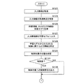
図4は、制御部10の処理手順の一例を示すフローチャートである。制御部10は、図4のフローチャートに示す処理手順を繰り返し実行する。制御部10は、例えば所定のコントロール周期(例えば30ミリ秒)で繰り返し実行する。 FIG. 4 is a flowchart illustrating an example of a processing procedure of the control unit 10. The control unit 10 repeatedly executes the processing procedure shown in the flowchart of FIG. The control unit 10 repeatedly executes, for example, at a predetermined control cycle (for example, 30 milliseconds).
制御部10は、入出力部14によって人力駆動車Aの走行に関する入力情報を取得する(ステップS101)。ステップS101にて制御部10は「取得部」である。ステップS101において制御部10は、入出力部14によって入力されるセンサ群S1−S5、S61−S63からの信号レベルをコントロール周期毎に参照し、制御部10の内部メモリまたは入出力部14が内蔵するメモリに一時記憶する。
The control unit 10 acquires input information on the traveling of the manually driven vehicle A by the input / output unit 14 (Step S101). In step S101, the control unit 10 is an “acquisition unit”. In step S101, the control unit 10 refers to the signal levels from the sensor groups S1-S5 and S61-S63 input by the input /
制御部10は、ステップS101で取得した入力情報を学習モデル1Mの入力層131に入力する(ステップS103)。
The control unit 10 inputs the input information acquired in step S101 to the
制御部10は、ステップS103の入力情報の入力によって学習モデル1Mから出力される制御対象のコンポーネントの制御に関する出力情報を特定する(ステップS105)。制御部10はステップS105において例えば、変速機Eの変速段数または変速比の判別結果を出力情報として特定する。
The control unit 10 specifies output information related to control of the component to be controlled, which is output from the
制御部10は、特定された出力情報に基づく制御対象の状態を参照する(ステップS107)。制御部10は、特定された出力情報が示す制御内容と、参照した状態との間の関係に基づき、制御信号の出力が必要であるか否かを判断する(ステップS109)。 The control unit 10 refers to the state of the control target based on the specified output information (Step S107). The control unit 10 determines whether a control signal needs to be output based on the relationship between the control content indicated by the specified output information and the referenced state (step S109).
ステップS109で必要であると判断された場合(S109:YES)、制御部10は特定された制御に関する出力情報に基づく制御信号を制御対象へ出力する(ステップS111)。ステップS109で不要であると判断された場合(S109:NO)、制御部10は、ステップS111を省略して次の処理へ進める。ステップS107の参照およびステップS109の判断処理は必須ではない。この場合、制御部10はステップS105において例えば、変速機Eの変速段数または変速比の判別結果を出力情報として特定し、制御部10は特定された出力情報に基づく制御対象の状態を参照することなく、制御部10は特定された制御に関する出力情報に基づく制御信号を制御信号を出力してもよい(S111)。 If it is determined in step S109 that the control is necessary (S109: YES), the control unit 10 outputs a control signal based on the output information on the specified control to the control target (step S111). If it is determined in step S109 that it is unnecessary (S109: NO), the control unit 10 skips step S111 and proceeds to the next process. The reference in step S107 and the determination processing in step S109 are not essential. In this case, in step S105, the control unit 10 specifies, for example, the determination result of the gear position or the gear ratio of the transmission E as output information, and the control unit 10 refers to the state of the control target based on the specified output information. Alternatively, the control unit 10 may output a control signal based on the output information regarding the specified control (S111).
制御部10は、ステップS111の処理後の所定時間内で、ステップS105にて特定した学習モデルから出力された出力情報を評価する(ステップS113)。ステップS113において制御部10は「評価部」である。制御部10はステップS113において、学習モデル1Mから出力された出力情報によるコンポーネント、例えば変速機Eの制御がスムーズであったか否かに基づき評価する。ステップS113の評価処理は後述する。
The control unit 10 evaluates the output information output from the learning model specified in step S105 within a predetermined time after the processing in step S111 (step S113). In step S113, the control unit 10 is an “evaluation unit”. In step S113, the control unit 10 evaluates a component based on the output information output from the
制御部10は、ステップS105で学習モデル1Mから出力された出力情報を、ステップS113で取得した入力情報にラベル付けすることによって教師データを作成する(ステップS115)。制御部10は、教師データにステップS113で得られる評価結果を報酬として付与し(ステップS117)、報酬と共にステップS115で作成した教師データを学習モデル1Mへ与えてこれを更新し(ステップS119)、処理を終了する。ステップS117において制御部20は、評価の度合いが高い、または低いほど、大きい重みを付与してもよい。例えば制御部20は、高評価であるほどに大きい重み付きの報酬を示す指標値を付与する。また、例えば制御部20は、低評価であるほどに大きい重み付きの罰則を示す指標値を付与する。制御部20は、報酬を示す指標値のみを付与してもよく、罰則を示す指標値のみを付与してもよい。
The control unit 10 creates teacher data by labeling the output information output from the
図5は、制御部10による評価処理手順の一例を示すフローチャートである。制御部10は、入出力部14によって人力駆動車Aの変速機Eを含むコンポーネントの制御の際の駆動機構Bに掛かるトルクをトルクセンサS3によって検知する(ステップS201)。制御部10は、検知したトルクに基づいて報酬に対応する第1の指標値(例えばQ学習におけるQ値)を算出する(ステップS203)。ステップS203にて制御部10は、トルクに応じてスムーズであったか否かを判断し、判断に応じて評価する。トルクが極端に大きい場合、制御の結果ユーザが力を掛けて運転していると推測される。この場合制御部10は、制御がスムーズでなかったと判断できる。制御部10は、トルクが小さい程に制御がスムーズであったと判断し、報酬の評価を向上させて算出する。
FIG. 5 is a flowchart illustrating an example of an evaluation processing procedure performed by the control unit 10. The control unit 10 detects the torque applied to the drive mechanism B when the components including the transmission E of the manually driven vehicle A are controlled by the input /
ステップS203において制御部10は例えば、トルクの大きさに負の符号を付し、所定の値を加算し、検知したトルクが所定値以下である場合には第1の指標値が正の値となるように第1の指標値を算出してもよい。制御部10は、トルクが大きい程に、絶対値が大きな負の値が指標値(罰則値)として与えられるように第1の指標値を算出してもよい。ステップS203において制御部10は他の例では、ステップS201で異なる時点で駆動機構Bに掛かるトルクを検知し、トルクの変動に応じてスムーズであったか否かを判断し、判断に応じて第1の指標値を算出する。他の例の場合、トルクの変動が小さい程に、制御がスムーズであったと判断できるので、制御部10は報酬を高評価として第1の指標値を算出する。 In step S203, for example, the control unit 10 assigns a negative sign to the magnitude of the torque and adds a predetermined value. If the detected torque is equal to or less than the predetermined value, the first index value is set to a positive value. The first index value may be calculated as follows. The control unit 10 may calculate the first index value so that a negative value having a larger absolute value is given as an index value (penalty value) as the torque is larger. In step S203, in another example, the control unit 10 detects the torque applied to the driving mechanism B at a different time in step S201, determines whether or not the driving mechanism B is smooth in accordance with the change in the torque, and determines the first based on the determination. Calculate the index value. In the case of another example, it can be determined that the smaller the fluctuation of the torque, the smoother the control was, so the control unit 10 calculates the first index value with the reward being evaluated highly.
制御部10は、ジャイロセンサS4から得られるコンポーネントの制御の際の人力駆動車Aの姿勢を検知し(ステップS205)、検知した姿勢に応じて第2の指標値を算出する(ステップS207)。傾きの大きさによって制御の結果、人力駆動車Aが傾いたことが推測される。傾きが大きい場合制御部10は、制御がスムーズでなかったと判断できる。したがって制御部10は、ヨー、ロール、ピッチいずれの回転方向においても傾きが少ない程に制御がスムーズであったと判断し、報酬を高評価として算出する。 The control unit 10 detects the attitude of the manually driven vehicle A when controlling the components obtained from the gyro sensor S4 (Step S205), and calculates a second index value according to the detected attitude (Step S207). As a result of the control based on the magnitude of the inclination, it is presumed that the manually driven vehicle A is inclined. When the inclination is large, the control unit 10 can determine that the control is not smooth. Therefore, the control unit 10 determines that the control is smoother as the inclination is smaller in any of the rotation directions of yaw, roll, and pitch, and calculates the reward as high evaluation.
ステップS207において制御部10は例えば、姿勢を示す各方向における傾きの絶対値に負の符号を付し、傾きが所定角度以内である場合には正の値となるように第2の指標値を算出してもよい。制御部10は、姿勢が傾いている程に、絶対値が大きな負の値が指標値(罰則値)として与えられるように第2の指標値を算出してもよい。ステップS207において制御部10は他の例では、ステップS205で異なる時点でジャイロセンサS4から姿勢を検知し、姿勢の変動に基づいて第2の指標値を算出してもよい。この他の例の場合、姿勢の変動が小さい程に、制御がスムーズであったと判断できるので、制御部10は高評価として第2の指標値を算出する。 In step S207, for example, the control unit 10 assigns a negative sign to the absolute value of the inclination in each direction indicating the posture, and sets the second index value to a positive value when the inclination is within a predetermined angle. It may be calculated. The control unit 10 may calculate the second index value such that a negative value having a larger absolute value is given as an index value (penalty value) as the posture is inclined. In another example, in step S207, the control unit 10 may detect the posture from the gyro sensor S4 at a different time in step S205, and calculate the second index value based on the change in the posture. In the case of this other example, it can be determined that the smaller the change in the posture is, the smoother the control is. Therefore, the control unit 10 calculates the second index value as high evaluation.
制御部10は、振動センサS7から得られるコンポーネントの制御の際の人力駆動車Aの振動を検知し(ステップS209)、検知した振動に応じて報酬に対応する第3の指標値を算出する(ステップS211)。振動が大きい、または振動数が大きいほどに、人力駆動車Aにおける制御がスムーズでなかったと判断できる。制御部10は、振動が小さい程に制御がスムーズであったと判断し、報酬を高評価で算出する。 The control unit 10 detects the vibration of the manually driven vehicle A at the time of controlling the component obtained from the vibration sensor S7 (Step S209), and calculates a third index value corresponding to the reward according to the detected vibration (Step S209). Step S211). It can be determined that the larger the vibration or the higher the frequency, the more the control in the manually driven vehicle A was not smooth. The control unit 10 determines that the control is smoother as the vibration is smaller, and calculates the reward with a higher evaluation.
ステップS209において制御部10は例えば、入出力部14によって振動センサS7から得られる振動波形を取得する。制御部10は、振動波形からノイズを抽出し、ノイズの大きさに負の符号を付し、所定の値を加算して所定のノイズレベル以下である場合には報酬が正の値となるように第3の指標値を算出してもよい。制御部10は、所定のノイズレベル以下である場合には所定の関数により指標値を算出し、ノイズが小さい程に高報酬が与えられるように傾斜を与える。
In step S209, the control unit 10 acquires a vibration waveform obtained from the vibration sensor S7 by the input /
制御部10は、テンションセンサS8から得られる信号からコンポーネントの制御の際の人力駆動車AのチェーンB4のテンションを測定する(ステップS213)。制御部10は、測定したテンションに応じて報酬に対応する第4の指標値を算出する(ステップS215)。テンションが所定範囲にある場合、制御部10は制御がスムーズであったと判断し、報酬を高評価で算出する。 The control unit 10 measures the tension of the chain B4 of the manually driven vehicle A at the time of component control from the signal obtained from the tension sensor S8 (step S213). The control unit 10 calculates a fourth index value corresponding to the reward according to the measured tension (Step S215). When the tension is within the predetermined range, the control unit 10 determines that the control is smooth, and calculates the reward with a high evaluation.
ステップS213において制御部10は、異なる時点におけるテンションを算出し、ステップS215においてテンションの変動に基づいて第4の指標値を算出してもよい。 In step S213, the control unit 10 may calculate the tension at different points in time, and in step S215, calculate the fourth index value based on the change in the tension.
制御部10は、姿勢センサS61−S63から得られる信号からコンポーネントの制御の際の人力駆動車Aのユーザの姿勢を検知し(ステップS217)、検知したユーザの姿勢に応じて報酬に対応する第5の指標値を算出する(ステップS219)。ステップS217において制御部10は、異なる時点における姿勢の変動から、ユーザの姿勢の揺れを検知してもよい。制御部10は、ユーザの姿勢が大きく傾くほど、または姿勢の揺れ幅が大きい程に、人力駆動車Aにおける制御がスムーズでなかったと判断できる。制御部10は、ユーザの姿勢の傾きが小さい程、揺れ幅が小さい程に、制御がスムーズであったと判断し、報酬を高評価で算出する。 The control unit 10 detects the posture of the user of the manually driven vehicle A at the time of controlling the component from the signals obtained from the posture sensors S61 to S63 (step S217), and responds to the reward corresponding to the detected posture of the user. 5 is calculated (step S219). In step S217, the control unit 10 may detect the fluctuation of the posture of the user from the fluctuation of the posture at different time points. The control unit 10 can determine that the control in the manually driven vehicle A is not smooth as the posture of the user is greatly inclined or the swing width of the posture is larger. The control unit 10 determines that the control is smoother as the inclination of the posture of the user is smaller and the swing width is smaller, and calculates the reward with a high evaluation.
制御部10は、算出された第1の指標値〜第5の指標値に基づき、総合指標値を算出する(ステップS221)。ステップS221において制御部10は例えば第1の指標値〜第5の指標値を加算してもよいし、重みを付与してから加算してもよい。制御部10は第1の指標値〜第5の指標値を乗算してもよいし、所定の評価関数を用いて算出してもよい。制御部10は、ステップS221で求めた総合指標値を評価結果として処理を図4のフローチャートにおけるステップS115へ戻す。 The control unit 10 calculates a comprehensive index value based on the calculated first to fifth index values (Step S221). In step S221, the control unit 10 may add the first to fifth index values, for example, or may add weights after adding the weights. The control unit 10 may multiply the first to fifth index values, or may calculate using a predetermined evaluation function. The control unit 10 returns the process to step S115 in the flowchart of FIG. 4 using the comprehensive index value obtained in step S221 as an evaluation result.
図5のフローチャートに示す処理手順はあくまで例示である、制御部10はトルクセンサS3、ジャイロセンサS4、振動センサS7、テンションセンサS8および姿勢センサS61−S63のいずれか1つのみから指標値を算出してもよい。つまり、図4のフローチャートにおけるステップS115の処理は、第1の指標値、第2の指標値、第3の指標値、第4の指標値および第5の指標値の内のいずれか1つのみを用いて実行されてもよい。ステップS115の処理は、第1の指標値、第2の指標値、第3の指標値、第4の指標値および第5の指標値の内の任意の2つ、または3つを用いて実行されてもよい。 The processing procedure shown in the flowchart of FIG. 5 is merely an example. The control unit 10 calculates an index value from only one of the torque sensor S3, the gyro sensor S4, the vibration sensor S7, the tension sensor S8, and the posture sensors S61 to S63. May be. That is, only one of the first index value, the second index value, the third index value, the fourth index value, and the fifth index value is processed in step S115 in the flowchart of FIG. May be performed using The process of step S115 is performed using any two or three of the first index value, the second index value, the third index value, the fourth index value, and the fifth index value. May be done.
図5のフローチャートにおける第1の指標値、第2の指標値、第3の指標値、第4の指標値及び第5の指標値の算出は他の例では、検知された物理量が夫々所定値以上であるか否かを判断し、所定値以上である場合には、低評価となるように算出されてもよい。 In another example, the first index value, the second index value, the third index value, the fourth index value, and the fifth index value in the flowchart of FIG. It is determined whether or not it is above, and if it is more than a predetermined value, it may be calculated so as to have a low evaluation.
このように、学習モデル1Mから出力される出力情報に基づく制御に対する評価によって、学習モデル1Mが更新されるから、ユーザの運転の仕方に見合った制御データを出力する学習モデル1Mが作成される。
As described above, since the
(第2実施形態)
図6は、第2実施形態における制御ユニット100の内部構成を示すブロック図である。第2実施形態における人力駆動車Aおよび制御ユニット100の構成は、以下に説明する記憶部および処理の詳細以外は第1実施形態と同様であるから、共通する構成に同一の符号を付して詳細な説明を省略する。第2実施形態において制御ユニット100の記憶部12は、異なる時点で時系列に取得した複数の入力情報を逐次一時的に記憶する。記憶部12は具体的には、人力駆動車Aに設けられたセンサ群S1−S5,S61−S63,S7,S8から入出力部14によって入力した入力情報を時間情報と共に複数サンプリング周期分記憶する。記憶部12は、複数サンプリング周期分の記憶領域を用いて巡回的に入力情報を記憶し、古い入力情報に自動的に上書きして記憶する。
(2nd Embodiment)
FIG. 6 is a block diagram illustrating an internal configuration of the
図7および図8は、第2実施形態における制御ユニット100の処理手順の一例を示すフローチャートである。第2実施形態における制御ユニット100の構成は、以下に示す評価処理の詳細以外は第1実施形態と同様であるから、同一の符号を付して詳細な説明を省略する。制御ユニット100の制御部10は、以下の処理手順を繰り返し実行する。
7 and 8 are flowcharts illustrating an example of a processing procedure of the
制御部10は、入出力部14によって人力駆動車Aの走行に関する入力情報を取得する(ステップS121)。ステップS121にて制御部10は「取得部」である。ステップS101において制御部10は、入出力部14によって入力されるセンサ群S1−S5、S61−S63からの信号レベルをコントロール周期毎に参照し、制御部10の内部メモリまたは入出力部14が内蔵するメモリに一時記憶する。
The control unit 10 acquires input information on the traveling of the manually driven vehicle A by the input / output unit 14 (Step S121). In step S121, the control unit 10 is an “acquisition unit”. In step S101, the control unit 10 refers to the signal levels from the sensor groups S1-S5 and S61-S63 input by the input /
制御部10は、ステップS121の入力情報の取得時点を特定する(ステップS123)。ステップS123において制御部10は、内蔵タイマから得られるタイミング情報を取得時点として使用してもよいし、時刻情報を使用してもよい。 The control unit 10 specifies the time of acquisition of the input information in step S121 (step S123). In step S123, the control unit 10 may use the timing information obtained from the built-in timer as the acquisition time, or may use the time information.
制御部10は、ステップS123で特定した取得時点を示す時間情報と、ステップS121で取得した入力情報とを対応付けて記憶部12に記憶する(ステップS125)。
The control unit 10 stores the time information indicating the acquisition time point identified in step S123 and the input information acquired in step S121 in the
制御部10は、ステップS121で取得した入力情報、または記憶部12に記憶してあるステップS121の取得時点までの複数の入力情報を、学習モデル1Mの入力層131に入力する(ステップS127)。
The control unit 10 inputs the input information acquired in Step S121 or a plurality of pieces of input information stored in the
制御部10は、学習モデル1Mから出力される制御対象のコンポーネントの制御に関する出力情報を特定する(ステップS129)。制御部10はステップS129において例えば、変速機Eの変速段数または変速比の判別結果を出力情報として特定する。
The control unit 10 specifies output information on the control of the component to be controlled, which is output from the
制御部10は、特定された出力情報に基づく制御対象の状態を参照する(ステップS131)。制御部10は、特定された出力情報が示す制御内容と、参照した状態との間の関係に基づき、制御信号の出力が必要であるか否かを判断する(ステップS133)。 The control unit 10 refers to the state of the control target based on the specified output information (Step S131). The control unit 10 determines whether a control signal needs to be output based on the relationship between the control content indicated by the specified output information and the referenced state (step S133).
ステップS133で必要であると判断された場合(S133:YES)、制御部10は特定された制御に関する出力情報に基づく制御信号を制御対象へ出力する(ステップS135)。ステップS133で不要であると判断された場合(S133:NO)、制御部10は、ステップS135の処理を省略して次の処理へ進める。この場合、制御部10はステップS129において例えば、変速機Eの変速段数または変速比の判別結果を出力情報として特定し、制御部10は特定された出力情報に基づく制御対象の状態を参照することなく、制御部10は特定された制御に関する出力情報に基づく制御信号を制御対象へ出力してもよい(S135)。 If it is determined in step S133 that the control is necessary (S133: YES), the control unit 10 outputs a control signal based on the output information on the specified control to the control target (step S135). If it is determined in step S133 that it is unnecessary (S133: NO), the control unit 10 skips the processing in step S135 and proceeds to the next processing. In this case, in step S129, the control unit 10 specifies, for example, the determination result of the gear position or the gear ratio of the transmission E as output information, and the control unit 10 refers to the state of the control target based on the specified output information. Instead, the control unit 10 may output a control signal based on the output information regarding the specified control to the control target (S135).
制御部10は所定時間内で、操作装置Dの操作部D1における制御対象のコンポーネントへの操作指示を受け付けたか否かを判断する(ステップS137)。 The control unit 10 determines whether an operation instruction for a component to be controlled in the operation unit D1 of the operation device D has been received within a predetermined time (step S137).
操作指示を受け付けたと判断された場合(S137:YES)、制御部10はステップS129で学習モデル1Mから出力された出力情報を、ステップS127で入力した複数の入力情報にラベル付けすることによって教師データを作成する(ステップS139)。ステップS139において制御部10は、操作指示のタイミングに対応する入力情報を記憶部12から選別して作成する。
When it is determined that the operation instruction has been received (S137: YES), the control unit 10 labels the output information output from the
制御部10は、実際の操作指示による制御データを参照し(ステップS141)、ステップS129で特定された学習モデル1Mからの出力情報との比較に基づき評価を付与する(ステップS143)。ステップS143が「評価部」に相当する。ステップS143にて制御部10は、ステップS139で参照した操作指示による制御データと、ステップS129で得られる学習モデル1Mからの制御に関する出力情報との乖離が大きい程に低い評価を与える。
The control unit 10 refers to the control data based on the actual operation instruction (step S141), and gives an evaluation based on comparison with the output information from the
制御部10は、ステップS143で付与した評価を含む罰則と共にステップS139で作成した教師データを学習モデル1Mへ与えてこれを更新し(ステップS145)、処理を終了する。
The control unit 10 gives the teacher model created in step S139 together with the penalties including the evaluation given in step S143 to the
ステップS137にて操作指示を受け付けていないと判断された場合(S137:NO)、制御部10は、制御部10はステップS129で学習モデル1Mから出力された制御に関する出力情報を、ステップS127で入力した入力情報にラベル付けすることによって教師データを作成する(ステップS147)。
When it is determined in step S137 that the operation instruction has not been received (S137: NO), the control unit 10 inputs the output information on the control output from the
制御部10は、作成した教師データに高評価を付与し(ステップS149)、学習モデル1Mへ与えてこれを更新し(S145)、処理を終了する。ステップS147が「評価部」に相当する。
The control unit 10 gives a high evaluation to the created teacher data (step S149), gives it to the
ステップS137〜S143の処理に加えて制御部10は、実際の操作指示内容をラベルとして付与することによって作成した教師データに基づいて学習モデル1Mを更新してもよい。この場合制御部10は、ステップS137で操作部D1にて指定操作を受け付けたと判断された場合、指定操作が行われたタイミングの前後に取得されて記憶部12に記憶してある複数の入力情報と、操作部D1での操作内容とにより学習モデル1Mを更新する。この場合制御部10は、実際の操作内容を入力データにラベル付けすることによって作成した教師データに高評価を付与して学習モデル1Mに与え、学習モデル1Mを更新する。操作部D1での指定内容は第1例では、変速機Eの変速段数および変速比の少なくともいずれか一方である。指定内容の第2例では、電動シートポストFにおける支持位置である。第3例では、電動サスペンションGの減衰率、ストローク量、およびロックアウト状態の設定情報である。
In addition to the processing in steps S137 to S143, the control unit 10 may update the
第2実施形態において制御部10は、ステップS127で複数の入力情報が入力されることに代替し、複数の入力情報の変動が入力されてもよい 。制御部10は、1サンプリング周期毎に前後の時点の変動を算出して変動値を入力層131に与えてもよいし、変動の傾向(増加、減少、維持)を入力層131に与えてもよいし、時系列分布に相当する波形を変動として算出してから入力層131に与えてもよい。変動値は1回または複数回の時間微分値を含んでいてもよい。
In the second embodiment, the control unit 10 may receive a change in a plurality of input information instead of inputting a plurality of input information in step S127. The control unit 10 may calculate the fluctuation at the time before and after each sampling cycle and give the fluctuation value to the
(第3実施形態)
第3実施形態では、制御ユニット100に代替して、ユーザの端末装置にて学習モデルの作成およびコンポーネント制御処理を実行する。図9は、制御システム200の構成を示すブロック図である。制御システム200は、端末装置2と制御ユニット100とを含む。第3実施形態における制御ユニット100は、制御部11、記憶部12、入出力部14および通信部16を含む。第3実施形態における制御ユニット100の構成部の内、第1実施形態および第2実施形態における制御ユニット100と共通する構成には同一の符号を付して詳細な説明を省略する。
(Third embodiment)
In the third embodiment, creation of a learning model and component control processing are executed by a user terminal device instead of the
第3実施形態における制御ユニット100の制御部11は、CPUを用いたプロセッサであり、内蔵するROMおよびRAM等のメモリを用い、各構成部を制御して処理を実行する。制御部11は、第1実施形態における制御ユニットの制御部10が行なった学習処理を実行しない。制御部11は、人力駆動車Aに設けられたセンサ群S1−S5,S61−S63を入出力部14によって入力し、通信部16を介して端末装置2へ送信する。制御部11は、操作装置Dにおける制御状態、操作装置Dから出力される操作信号を参照して通信部16を介して端末装置2へ送信する。制御部11は、操作装置Dからの出力される操作信号に基づき、または端末装置2からの指示に基づき、制御信号を制御対象の電動アクチュエータE1へ与える。
The
通信部16は通信ポートであり、制御部11は通信部16を介して端末装置2と情報を送受信する。通信部16は第1例では、USB(Universal Serial Bus)ポートである。通信部16は第2例では、Bluetooth(登録商標)等の近距離無線通信モジュールである。
The
端末装置2は、ユーザが使用する可搬型の小型の通信端末装置である。端末装置2は第1例では、スマートフォンである。端末装置2は第2例では、所謂スマートウォッチ等のウェアラブルデバイスである。スマートフォンである場合、人力駆動車AのハンドルバーA2にスマートフォン用保持部材を取り付けておき、この保持部材にスマートフォンを嵌めて用いてもよい(図10参照)。
The
端末装置2は、制御部20、記憶部21、表示部23、操作部24、撮像部25、および通信部26を備える。
The
制御部20は、CPU、GPU等のプロセッサと、メモリ等を含む。制御部20は、プロセッサ、メモリ、記憶部21、および通信部26を集積した1つのハードウェア(SoC:System On a Chip)として構成されていてもよい。制御部20は、記憶部21に記憶されているアプリプログラム20Pに基づき、人力駆動車Aの制御に関する出力情報の学習と、学習に基づくコンポーネント制御を実行する。
The
記憶部21は、例えばフラッシュメモリ等の不揮発性メモリを含む。記憶部21は、アプリプログラム20Pを記憶する。記憶部21は、制御部20の処理によって作成、更新される学習モデル2Mを記憶する。記憶部21は、制御部20が参照するデータを記憶する。アプリプログラム20Pは、記憶媒体29に記憶されたアプリプログラム29Pを読み出して記憶部21に複製されたものであってもよい。
The
表示部23は、液晶パネルまたは有機ELディスプレイ等のディスプレイ装置を含む。操作部24は、ユーザの操作を受け付けるインタフェースであり、物理ボタン、ディスプレイ内蔵のタッチパネルデバイスを含む。操作部24は、物理ボタンまたはタッチパネルにて表示部23で表示している画面上における操作を受け付けることが可能である。
The
音声入出力部22は、スピーカおよびマイクロフォン等を用いる。音声入出力部22は、音声認識部221を備え、マイクロフォンにて入力音声から操作内容を認識して操作を受け付けることが可能である。
The audio input / output unit 22 uses a speaker, a microphone, and the like. The voice input / output unit 22 includes a
撮像部25は、撮像素子を用いて得られる映像信号を出力する。制御部20は、任意のタイミングで撮像部25の撮像素子にて撮像される画像を取得できる。
The
通信部26は、制御ユニット100の通信部16に対応する通信モジュールである。通信部26は第1例では、USB通信ポートである。通信部26は第2例では、近距離無線モジュールである。
The
第3実施形態において制御ユニット100は継続的に、入出力部14によって人力駆動車Aに設けられたセンサ群S1−S5,S61−S63,S7,S8から得られる入力情報を取得し、通信部16を介して端末装置2へ送信する。
In the third embodiment, the
端末装置2の制御部20は、アプリプログラム20Pに基づき、深層学習の学習アルゴリズムによる学習モデル2Mを用いて変速機Eを含むコンポーネントを自動制御する制御部として機能すると共に、学習モデル2Mを更新する作成部として機能する。端末装置2は「制御データ作成装置」および「コンポーネント制御装置」に相当する。
Based on the
端末装置2の動作は、第1実施形態又は第2実施形態に示した制御ユニット100の制御部10の動作と同様である。ただし第3実施形態において「作成装置」又は「コンポーネント制御装置」に相当する端末装置2は、操作部24または撮像部25にて得られる情報に基づいてユーザの評価を受け付け、評価の内容に応じて学習モデル2Mを更新する。
The operation of the
図10〜図11は、アプリプログラム20Pに基づいて表示される画面例を示す図である。図10に示す例では、端末装置2はスマートフォンであってハンドルバーA2にユーザが表示部23を視認できるように取り付けられている。図10では、アプリプログラム20Pに基づき表示部23に表示されるメイン画面230が示されている。制御部20は、アプリプログラム20Pの実行が選択された場合、表示部23にメイン画面230に表示させる。制御部20は、アプリプログラム20Pの実行を開始すると制御ユニット100との間で通信接続を確立させる。制御部20は図13に示すように、通信状態を示すメッセージをメイン画面230に表示させる。メイン画面230には、学習モデル2Mに基づく自動制御の開始を受け付けるボタン234が含まれる。ボタン234が選択された場合、学習モデル2Mから出力される制御データに基づく自動制御を行ないつつ学習モデル2Mを更新する処理を開始する。
10 to 11 are diagrams illustrating examples of screens displayed based on the
図11は、自動制御開始を受け付けるボタン234が選択された場合に表示される自動制御モード画面236の内容例を示す。自動制御モード画面236では、制御部20が変速機Eへの制御信号の出力を必要と判断し、制御信号を出力した場合、変速段数または変速比を変更したことを示すメッセージを表示または音声入出力部22から音声を出力させる。制御部20は、このメッセージに対する評価を受け付ける。制御部20は、以下に示す例のいずれかによって、学習モデル2Mから出力された出力情報に基づく制御部20による制御内容に対してユーザ操作を受け付け、操作内容によって制御内容の評価を受け付ける。制御部20は「評価受付部」である。
FIG. 11 shows an example of the content of the automatic
「評価受付部」の第1例は、図11に示す自動制御モード画面236に含まれる評価を受け付ける高評価ボタン238と低評価ボタン240とである。制御部20は、評価ボタン238,240の選択操作を操作部24のタッチパネルでこれを認識し、評価を受け付ける。図11の例における高評価ボタン238は、変速段数または変速比の自動制御が快適であった場合に選択される。低評価ボタン240は、自動制御が快適でなかった場合に選択される。制御部20はいずれのボタン238,240が選択されたかを認識して受け付けた評価内容を認識する。「評価受付部」の第1例の変形例として低評価ボタン240のみが表示されてもよい。「評価受付部」の第1例の変形例として、この場合、変更した変速段数または変速比が重すぎる(OUTWARDすぎる)と評価するボタンと、軽すぎる(INWARDすぎる)と評価するボタンであってもよい。
A first example of the “evaluation receiving unit” is a
「評価受付部」の第2例は、操作部D1に設けられている物理的なボタンであってもよい。操作部D1に特定の評価受付ボタンを設けてもよい。評価受付ボタンを操作装置Dの近傍に別途設けられてもよい。制御部20は、特定の評価受付ボタンが押下されたか否か、その他、汎用的なボタンの押され方、レバー操作との組み合わせによって評価内容を認識することができる。「評価受付部」の第3例は、音声入出力部22の音声認識部221である。制御部20は、音声認識部221にて認識したユーザの音声に基づいて自動制御が快適であったか否かを認識する。「評価受付部」の第4例は、撮像部25である。制御部20は、撮像部25でユーザの顔を撮像して得られる撮像画像に基づきユーザの表情を特定し、快適か否かを判別し、判別結果を評価として受け付ける。
A second example of the “evaluation receiving unit” may be a physical button provided on the operation unit D1. A specific evaluation reception button may be provided in the operation unit D1. An evaluation accepting button may be separately provided near the operation device D. The
図12は、第3実施形態における制御部20の処理手順の一例を示すフローチャートである。制御部20は、以下の処理手順を繰り返し実行する。所定のコントロール周期(例えば30ミリ秒)で実行してもよい。
FIG. 12 is a flowchart illustrating an example of a processing procedure of the
制御部20は、制御ユニット100から得られる人力駆動車Aの走行に関する入力情報を通信部26によって取得する(ステップS301)。ステップS301において制御部20は、制御ユニット100の制御部10がセンサ群S1−S5,S61−S63からの信号レベルをコントロール周期毎に参照し、制御部10の内部メモリまたは入出力部14が内蔵するメモリに一時記憶したものを取得する。
The
制御部20は、ステップS301で取得した入力情報を学習モデル2Mに入力する(ステップS303)。
The
制御部20は、学習モデル2Mから出力される制御対象の制御に関する出力情報を特定する(ステップS305)。制御部20はステップS305において例えば、変速機Eの変速段数または変速比の判別結果を特定する。
The
制御部20は、制御対象の状態を参照する(ステップS307)。制御部20はステップS307において、制御ユニット100を介して例えば変速機Eからフィードバックされる変速段数または変速比を参照してもよい。制御部20は、ステップS305で特定した出力情報が示す制御内容と、ステップS307で参照した状態との間の関係に基づき、制御信号の出力が必要であるか否かを判断する(ステップS309)。ステップS309で必要であると判断された場合(S309:YES)、制御部20は制御指示を制御ユニット100へ出力する(ステップS311)。制御部20は、制御指示の内容を表示部23に出力する(ステップS313)。ステップS309で不要と判断された場合(S309:NO)、制御部20は処理をステップS315へ進める。
The
制御部20は、ステップS311の処理後の所定時間内でユーザ評価を受け付ける(ステップS315)。
The
制御部20は、受け付けた評価が高評価であるか否かを判断する(ステップS317)。高評価であると判断された場合(S317:YES)、制御部20は、ステップS305で学習モデル2Mから出力された制御データを、ステップS303で入力した入力情報にラベル付けすることによって教師データを作成する(ステップS319)。
The
制御部20は、作成した教師データに高評価を付与し(ステップS321)、学習モデル1Mへ高評価を報酬として与えてこれを更新し(ステップS323)、処理を終了する。ステップS321が「評価部」に相当する。
The
ステップS317で高評価でないと判断された場合(S317:NO)、制御部20は、ステップS305で学習モデル2Mから出力された制御データを、ステップS303で入力した入力情報にラベル付けすることによって教師データを作成する(ステップS325)。
If it is determined in step S317 that the evaluation is not high evaluation (S317: NO), the
制御部20は、作成した教師データに低評価を付与する(ステップS327)。ステップS327にて制御部20は「評価部」である。制御部20は、ステップS327で付与した評価を含む罰則と共にステップS325で作成した教師データを学習モデル1Mへ与えてこれを更新し(S323)、処理を終了する。
The
第3実施形態において端末装置2は、第2実施形態同様に逐次、時系列に入力情報を逐次記憶部21に一時記憶してもよい。この場合制御部20は、ステップS315で評価を受け付けた場合に、ステップS319,S325において、評価が受け付けられたタイミングの前後に取得されて記憶部21に記憶してある複数の入力情報と、評価対象の制御内容と、受け付けた評価とを含む教師データを作成する。制御部20は、評価受付部にて評価が受け付けられたタイミングの前後に取得された複数の入力情報を入力とし、学習モデル2Mから出力された出力情報と、評価受付部で受け付けた評価とを含む教師データに基づいて学習モデル2Mを更新する。
In the third embodiment, the
第1実施形態から第4実施形態において、学習モデル1Mまたは学習モデル2Mから出力される出力情報として、主に、変速機Eの制御に関する制御データについて説明した。制御対象の人力駆動車Aのコンポーネントは、変速機Eに代えて、電動シートポストFであってもよいし、電動サスペンションGであってもよい。制御対象の人力駆動車Aのコンポーネントは、変速機E、電動シートポストF、および電動サスペンションGであってもよいし、電動シートポストFおよび電動サスペンションGであってもよい。
In the first to fourth embodiments, control data related to control of the transmission E has been mainly described as output information output from the
100…制御ユニット(作成装置、コンポーネント制御装置)、10,11…制御部、12…記憶部、1M…学習モデル、1P…制御プログラム、2…端末装置、20…制御部、21…記憶部、2M…学習モデル、20P…アプリプログラム、A4…後輪、B1…クランク、B3…第2スプロケット組立体、D…操作装置、D1…操作部、E…変速機、E1…電動アクチュエータ、F…電動シートポスト、G…電動サスペンション、S1…速度センサ、S2…ケイデンスセンサ、S3…トルクセンサ、S4…ジャイロセンサ、S5…画像センサ、S61,S62,S63…姿勢センサ、S7…振動センサ、S8…テンションセンサ。 100 control unit (creating device, component control device), 10, 11 control unit, 12 storage unit, 1M learning model, 1P control program, 2 terminal device, 20 control unit, 21 storage unit, 2M: learning model, 20P: application program, A4: rear wheel, B1: crank, B3: second sprocket assembly, D: operating device, D1: operating unit, E: transmission, E1: electric actuator, F: electric Seat post, G: electric suspension, S1: speed sensor, S2: cadence sensor, S3: torque sensor, S4: gyro sensor, S5: image sensor, S61, S62, S63: posture sensor, S7: vibration sensor, S8: tension Sensor.
Claims (15)
前記取得部が取得した入力情報に基づいて前記人力駆動車のコンポーネントの制御に関する出力情報を出力する、学習モデルを学習アルゴリズムによって作成する作成部と、
前記学習モデルから出力された出力情報を評価する評価部と
を備え、
前記作成部は、前記評価部の評価と、前記出力情報の出力に対応する入力情報と、前記出力情報とを含む教師データに基づいて前記学習モデルを更新する、制御データ作成装置。 An acquisition unit configured to acquire input information on traveling of a manually driven vehicle,
A creation unit that creates a learning model by a learning algorithm, which outputs output information related to control of the component of the manually driven vehicle based on the input information obtained by the acquisition unit.
An evaluation unit that evaluates output information output from the learning model,
The control data creation device, wherein the creation unit updates the learning model based on teacher data including the evaluation of the evaluation unit, input information corresponding to the output of the output information, and the output information.
前記取得部は、時系列に複数の入力情報を逐次一時記憶する記憶部を備え、
前記作成部は、前記操作部にて指定操作を受け付けた場合、前記指定操作が行われたタイミングの前後に取得された複数の入力情報を入力データとし、前記入力データと前記操作部での操作内容とにより前記学習モデルを更新する、請求項1〜9のいずれか一項に記載の制御データ作成装置。 An operation unit that receives a designation operation related to the output information,
The acquisition unit includes a storage unit that sequentially and temporarily stores a plurality of pieces of input information in a time series,
The creating unit, when a designation operation is received by the operation unit, sets a plurality of pieces of input information acquired before and after the timing at which the designation operation is performed as input data, and the input data and an operation by the operation unit The control data creation device according to claim 1, wherein the learning model is updated according to contents.
前記入力情報を取得する取得部と、
前記取得部が取得した入力情報を前記学習モデルに入力することにより出力される出力情報に基づき前記コンポーネントを制御する制御部と、
前記制御部による制御内容を評価する評価部と、
前記評価部の評価と、前記評価に対応する入力情報と、評価対象の制御内容とを含む教師データに基づいて前記学習モデルを更新する、コンポーネント制御装置。 A learning model created by a learning algorithm to output output information on control of the components of the manually driven vehicle, with input information on the traveling of the manually driven vehicle as an input,
An acquisition unit that acquires the input information;
A control unit that controls the component based on output information output by inputting the input information obtained by the obtaining unit to the learning model,
An evaluation unit that evaluates the control content of the control unit,
A component control device that updates the learning model based on teacher data including an evaluation of the evaluation unit, input information corresponding to the evaluation, and control content of an evaluation target.
前記評価受付部により評価を受け付けた場合、前記評価が受け付けられたタイミングの前後に取得された複数の入力情報と、前記制御内容と、前記評価受付部で受け付けた評価とを含む教師データに基づいて前記学習モデルを更新する、請求項11に記載のコンポーネント制御装置。 The evaluation unit includes an evaluation reception unit that receives evaluation of control content by the control unit,
When the evaluation is received by the evaluation receiving unit, based on a plurality of pieces of input information obtained before and after the timing at which the evaluation is received, the control content, and teacher data including the evaluation received by the evaluation receiving unit. The component control device according to claim 11, wherein the learning model is updated by updating the learning model.
取得した入力情報を入力として、前記人力駆動車のコンポーネントの制御に関する出力情報を出力する学習モデルを学習アルゴリズムによって作成し、
前記学習モデルから出力された出力情報を評価し、
評価と、前記出力情報の出力に対応する入力情報と、評価対象の出力情報とを含む教師データに基づいて前記学習モデルを更新する制御データ作成方法。 Acquires input information related to driving of a manually driven vehicle,
With the obtained input information as input, a learning model is created by a learning algorithm that outputs output information regarding control of the components of the manually driven vehicle,
Evaluate the output information output from the learning model,
A control data generation method for updating the learning model based on teacher data including evaluation, input information corresponding to output of the output information, and output information to be evaluated.
前記入力情報を入力として、前記人力駆動車のコンポーネントの制御に関する出力情報を出力するべく学習アルゴリズムにより作成された学習モデルに、取得された入力情報を入力することにより出力される出力情報を特定し、
特定した出力情報に基づき前記コンポーネントを制御し、
制御内容を評価し、
評価と、前記評価に対応する入力情報と、評価対象の制御内容とを含む教師データに基づいて前記学習モデルを更新する、コンポーネント制御方法。 Acquires input information related to driving of a manually driven vehicle,
With the input information as input, specify the output information to be output by inputting the obtained input information to a learning model created by a learning algorithm to output output information related to control of the component of the manually driven vehicle. ,
Controlling the component based on the specified output information,
Evaluate the control content,
A component control method for updating the learning model based on teacher data including an evaluation, input information corresponding to the evaluation, and control content of an evaluation target.
取得した入力情報を入力として、前記人力駆動車のコンポーネントの制御に関する出力情報を出力する学習モデルを学習アルゴリズムによって作成し、
前記学習モデルから出力された出力情報を評価し、
評価と、前記出力情報の出力に対応する入力情報と、評価対象の出力情報とを含む教師データに基づいて前記学習モデルを更新する
処理を、コンピュータに実行させるコンピュータプログラム。 Acquires input information related to driving of a manually driven vehicle,
With the obtained input information as input, a learning model is created by a learning algorithm that outputs output information regarding control of the components of the manually driven vehicle,
Evaluate the output information output from the learning model,
A computer program that causes a computer to execute a process of updating the learning model based on teacher data including evaluation, input information corresponding to output of the output information, and output information to be evaluated.
Priority Applications (18)
| Application Number | Priority Date | Filing Date | Title |
|---|---|---|---|
| JP2018130244A JP6985217B2 (en) | 2018-07-09 | 2018-07-09 | Control data creation device, component control device, control data creation method, component control method, and computer program |
| US16/453,319 US11521117B2 (en) | 2018-07-09 | 2019-06-26 | Control data creation device, component control device, control data creation method, component control method and computer program |
| US16/503,584 US11731723B2 (en) | 2018-07-09 | 2019-07-04 | Rider recognition device for human-powered vehicle and control system of human-powered vehicle |
| US16/503,582 US20200011691A1 (en) | 2018-07-09 | 2019-07-04 | Information processing device |
| US16/503,586 US20200010138A1 (en) | 2018-07-09 | 2019-07-04 | Information processing device |
| DE102019118274.3A DE102019118274A1 (en) | 2018-07-09 | 2019-07-05 | Electronic device and human powered vehicle |
| DE102019118278.6A DE102019118278A1 (en) | 2018-07-09 | 2019-07-05 | Control data generation device, component control device, control data generation method, component control method and computer program |
| DE102019118273.5A DE102019118273A1 (en) | 2018-07-09 | 2019-07-05 | Information processing apparatus |
| DE102019118281.6A DE102019118281A1 (en) | 2018-07-09 | 2019-07-05 | Generation device, component control device, generation method, component control method, computer program |
| DE102019118279.4A DE102019118279A1 (en) | 2018-07-09 | 2019-07-05 | Information processing apparatus |
| DE102019118280.8A DE102019118280A1 (en) | 2018-07-09 | 2019-07-05 | Driver detection device for a human powered vehicle and control system for a human powered vehicle |
| DE102019118277.8A DE102019118277A1 (en) | 2018-07-09 | 2019-07-05 | HUMAN-POWERED VEHICLE CONTROL DEVICE, ELECTRONIC DEVICE AND HUMAN-POWERED VEHICLE CONTROL SYSTEM |
| DE102019118282.4A DE102019118282A1 (en) | 2018-07-09 | 2019-07-05 | Component of a human powered vehicle, mobile electronic device and equipment for a human powered vehicle |
| DE102019118275.1A DE102019118275A1 (en) | 2018-07-09 | 2019-07-05 | Generation device, component control device, generation method, component control method, computer program and learning model |
| US16/505,560 US11597470B2 (en) | 2018-07-09 | 2019-07-08 | Human-powered vehicle component, mobile electronic device, and equipment for human-powered vehicle |
| US16/505,570 US11527980B2 (en) | 2018-07-09 | 2019-07-08 | Electronic device and human-powered vehicle system |
| US16/505,578 US11527981B2 (en) | 2018-07-09 | 2019-07-08 | Human-powered vehicle control device, electronic device, and human-powered vehicle control system |
| US17/692,628 US11912371B2 (en) | 2018-07-09 | 2022-03-11 | Human-powered vehicle component, mobile electronic device, and equipment for human-powered vehicle |
Applications Claiming Priority (1)
| Application Number | Priority Date | Filing Date | Title |
|---|---|---|---|
| JP2018130244A JP6985217B2 (en) | 2018-07-09 | 2018-07-09 | Control data creation device, component control device, control data creation method, component control method, and computer program |
Publications (2)
| Publication Number | Publication Date |
|---|---|
| JP2020006834A true JP2020006834A (en) | 2020-01-16 |
| JP6985217B2 JP6985217B2 (en) | 2021-12-22 |
Family
ID=69102199
Family Applications (1)
| Application Number | Title | Priority Date | Filing Date |
|---|---|---|---|
| JP2018130244A Active JP6985217B2 (en) | 2018-07-09 | 2018-07-09 | Control data creation device, component control device, control data creation method, component control method, and computer program |
Country Status (2)
| Country | Link |
|---|---|
| US (1) | US11521117B2 (en) |
| JP (1) | JP6985217B2 (en) |
Cited By (1)
| Publication number | Priority date | Publication date | Assignee | Title |
|---|---|---|---|---|
| JP2022019162A (en) * | 2020-07-17 | 2022-01-27 | トヨタ自動車株式会社 | Method for learning oil pressure of automatic transmission, controller of automatic transmission, control system of automatic transmission, vehicle controller and vehicle learning device |
Families Citing this family (2)
| Publication number | Priority date | Publication date | Assignee | Title |
|---|---|---|---|---|
| IT202000005530A1 (en) * | 2020-03-16 | 2021-09-16 | Motocicli Italiani S R L | PEDALING ASSISTANCE SYSTEM FOR ELECTRIC BICYCLE AND RELATED BICYCLE |
| DE102021130990A1 (en) * | 2021-11-25 | 2023-05-25 | Shimano Inc. | MOTORIZED COMPONENT AND CONTROL SYSTEM FOR A HUMAN-POWERED VEHICLE |
Citations (8)
| Publication number | Priority date | Publication date | Assignee | Title |
|---|---|---|---|---|
| JPH023756A (en) * | 1988-06-17 | 1990-01-09 | Nissan Motor Co Ltd | Speed change control device for automatic speed change gear for vehicle |
| JPH05203025A (en) * | 1992-01-24 | 1993-08-10 | Jatco Corp | Speed change control device for automatic transmission |
| JPH05296323A (en) * | 1992-04-17 | 1993-11-09 | Toyota Motor Corp | Tie-up judgement device for continuously variable transmission, and control device therefor |
| US6047230A (en) * | 1997-02-27 | 2000-04-04 | Spencer; Marc D. | Automatic bicycle transmission |
| JP2007272361A (en) * | 2006-03-30 | 2007-10-18 | Hitachi Ltd | Controller for plant |
| JP2009113717A (en) * | 2007-11-08 | 2009-05-28 | Fuji Heavy Ind Ltd | State estimation system |
| US20160288877A1 (en) * | 2015-04-01 | 2016-10-06 | Wick Werks, LLC | Bicycle derailleur with automatic alignment, and methods for automatic derailleur alignment |
| CN106896723A (en) * | 2017-03-31 | 2017-06-27 | 浙江大学 | A kind of intelligent automatic gear shifting control system of bicycle |
Family Cites Families (2)
| Publication number | Priority date | Publication date | Assignee | Title |
|---|---|---|---|---|
| US9676441B2 (en) | 2013-11-12 | 2017-06-13 | Giant Manufacturing Co. Ltd | Automatic shock absorber system for bicycle |
| EP2979970B1 (en) | 2014-08-01 | 2017-09-13 | Campagnolo S.R.L. | Bicycle electronic gearshift system and related method |
-
2018
- 2018-07-09 JP JP2018130244A patent/JP6985217B2/en active Active
-
2019
- 2019-06-26 US US16/453,319 patent/US11521117B2/en active Active
Patent Citations (8)
| Publication number | Priority date | Publication date | Assignee | Title |
|---|---|---|---|---|
| JPH023756A (en) * | 1988-06-17 | 1990-01-09 | Nissan Motor Co Ltd | Speed change control device for automatic speed change gear for vehicle |
| JPH05203025A (en) * | 1992-01-24 | 1993-08-10 | Jatco Corp | Speed change control device for automatic transmission |
| JPH05296323A (en) * | 1992-04-17 | 1993-11-09 | Toyota Motor Corp | Tie-up judgement device for continuously variable transmission, and control device therefor |
| US6047230A (en) * | 1997-02-27 | 2000-04-04 | Spencer; Marc D. | Automatic bicycle transmission |
| JP2007272361A (en) * | 2006-03-30 | 2007-10-18 | Hitachi Ltd | Controller for plant |
| JP2009113717A (en) * | 2007-11-08 | 2009-05-28 | Fuji Heavy Ind Ltd | State estimation system |
| US20160288877A1 (en) * | 2015-04-01 | 2016-10-06 | Wick Werks, LLC | Bicycle derailleur with automatic alignment, and methods for automatic derailleur alignment |
| CN106896723A (en) * | 2017-03-31 | 2017-06-27 | 浙江大学 | A kind of intelligent automatic gear shifting control system of bicycle |
Cited By (1)
| Publication number | Priority date | Publication date | Assignee | Title |
|---|---|---|---|---|
| JP2022019162A (en) * | 2020-07-17 | 2022-01-27 | トヨタ自動車株式会社 | Method for learning oil pressure of automatic transmission, controller of automatic transmission, control system of automatic transmission, vehicle controller and vehicle learning device |
Also Published As
| Publication number | Publication date |
|---|---|
| US20200012964A1 (en) | 2020-01-09 |
| JP6985217B2 (en) | 2021-12-22 |
| US11521117B2 (en) | 2022-12-06 |
Similar Documents
| Publication | Publication Date | Title |
|---|---|---|
| JP7007244B2 (en) | Creation device, component control device, creation method, component control method, computer program and learning model | |
| JP7324632B2 (en) | Output device, learning model generation method, and computer program | |
| JP2023091087A (en) | Control device, learning method of learning model, learning model, computer program, and storage medium | |
| JP6989452B2 (en) | Creation device, component control device, creation method, component control method, and computer program | |
| JP6985217B2 (en) | Control data creation device, component control device, control data creation method, component control method, and computer program | |
| WO2018123161A1 (en) | Electric assistance system and electrically assisted vehicle | |
| JP7193230B2 (en) | Control device for human-powered vehicle | |
| US11527981B2 (en) | Human-powered vehicle control device, electronic device, and human-powered vehicle control system | |
| JP7298989B2 (en) | Control device for human-powered vehicle | |
| US11597470B2 (en) | Human-powered vehicle component, mobile electronic device, and equipment for human-powered vehicle | |
| DE102019118278A1 (en) | Control data generation device, component control device, control data generation method, component control method and computer program | |
| CN1873734A (en) | Bicycle simulation system | |
| JPWO2018189841A1 (en) | Conversation information output device for vehicle and conversation information output method | |
| JP7337510B2 (en) | Output device, learning model generation method, computer program, and storage medium | |
| US20220161890A1 (en) | Motor controller for electric bicycles | |
| TWI814155B (en) | Assistive force control system and method for electric assisted bicycle | |
| US20200011691A1 (en) | Information processing device | |
| EP3389030A1 (en) | Device for presenting onomatopoeia regarding evaluation result for user action | |
| JP2020140382A (en) | Output device, computer program, and storage medium | |
| JP7356230B2 (en) | control system | |
| US20230182858A1 (en) | Human-powered vehicle control device, learning model creation method, learning model, human-powered vehicle control method and computer program | |
| JP2023085935A (en) | Device, method, and system for processing human power drive vehicle information and computer program | |
| US20230331341A1 (en) | Method for Determining a Driver State of a Motor-Assisted Vehicle; Method for Training a Machine Learning System; Motor-Assisted Vehicle | |
| JP2020098161A (en) | Information processing device | |
| JP2022176850A (en) | Control device for human-powered vehicle |
Legal Events
| Date | Code | Title | Description |
|---|---|---|---|
| A621 | Written request for application examination |
Free format text: JAPANESE INTERMEDIATE CODE: A621 Effective date: 20200831 |
|
| A977 | Report on retrieval |
Free format text: JAPANESE INTERMEDIATE CODE: A971007 Effective date: 20210525 |
|
| A131 | Notification of reasons for refusal |
Free format text: JAPANESE INTERMEDIATE CODE: A131 Effective date: 20210608 |
|
| A521 | Request for written amendment filed |
Free format text: JAPANESE INTERMEDIATE CODE: A523 Effective date: 20210804 |
|
| A131 | Notification of reasons for refusal |
Free format text: JAPANESE INTERMEDIATE CODE: A131 Effective date: 20210831 |
|
| A521 | Request for written amendment filed |
Free format text: JAPANESE INTERMEDIATE CODE: A523 Effective date: 20211018 |
|
| TRDD | Decision of grant or rejection written | ||
| A01 | Written decision to grant a patent or to grant a registration (utility model) |
Free format text: JAPANESE INTERMEDIATE CODE: A01 Effective date: 20211124 |
|
| A61 | First payment of annual fees (during grant procedure) |
Free format text: JAPANESE INTERMEDIATE CODE: A61 Effective date: 20211125 |
|
| R150 | Certificate of patent or registration of utility model |
Ref document number: 6985217 Country of ref document: JP Free format text: JAPANESE INTERMEDIATE CODE: R150 |