JP2020006103A - Attachment structure for storage tool for attaching to internal corner wall surface - Google Patents
Attachment structure for storage tool for attaching to internal corner wall surface Download PDFInfo
- Publication number
- JP2020006103A JP2020006103A JP2018132603A JP2018132603A JP2020006103A JP 2020006103 A JP2020006103 A JP 2020006103A JP 2018132603 A JP2018132603 A JP 2018132603A JP 2018132603 A JP2018132603 A JP 2018132603A JP 2020006103 A JP2020006103 A JP 2020006103A
- Authority
- JP
- Japan
- Prior art keywords
- outer peripheral
- peripheral frame
- storage tool
- corner
- wall
- Prior art date
- Legal status (The legal status is an assumption and is not a legal conclusion. Google has not performed a legal analysis and makes no representation as to the accuracy of the status listed.)
- Granted
Links
Images


Landscapes
- Bathtubs, Showers, And Their Attachments (AREA)
- Cabinets, Racks, Or The Like Of Rigid Construction (AREA)
Abstract
Description
本発明は、室内内壁の入隅部に取付けられる収納用具の取付構造に関する。 The present invention relates to a mounting structure of a storage tool mounted on a corner of an inner wall of a room.
従来、室内内壁の入隅部に取付けられる収納用具は、収納部の前方を上方から押圧されると、収納部の入隅角部側が上方に跳ね上がり、収納部が脱落する虞があるため、収納部を直接壁面にビス等を用いて固定する構造が広く用いられている。 Conventionally, the storage tool attached to the interior corner of the interior wall of the room has a problem that when the front of the storage part is pressed from above, the interior corner of the storage part jumps upward and the storage part may fall off. A structure in which a part is directly fixed to a wall surface using a screw or the like is widely used.
そこで、入隅双方の壁面に取付けられた支持具の支持片を、コーナー棚本体の案内溝に挿入して保持し、入隅部に配置した固定具とコーナー棚本体をビスで連接することで、コーナー棚本体の脱落防止と、取付け作業を容易に行う構造が開示されている。(特許文献1参照) Therefore, by inserting and holding the support pieces of the supports attached to the wall surfaces of both the corners into the guide grooves of the corner shelf main body, and connecting the fixtures arranged at the corners and the corner shelf body with screws. A structure for preventing the corner shelf main body from falling off and facilitating the mounting operation is disclosed. (See Patent Document 1)
また、板状の取付部材にボス部を設け、このボス部にコーナー棚の凹部を引掛けてコーナー棚を着脱可能にすると共に、取付部材を水平方向に移動させたり、ボス部を突出させることで、入隅の角度が多少鋭角や鈍角であっても、コーナー棚を装着できる構造が開示されている。(特許文献2参照)
さらに、特許文献2には、コーナー棚の左右両端に設けた縦溝に、取付部材に設けた転倒防止リブを嵌り込むことで、コーナー棚がひっくり返ることを防止する構造が開示されている。
In addition, a boss portion is provided on a plate-like mounting member, and a concave portion of a corner shelf is hooked on the boss portion to make the corner shelf detachable, and the mounting member is moved in a horizontal direction or the boss portion is projected. Thus, there is disclosed a structure in which a corner shelf can be mounted even if the angle of the corner is somewhat acute or obtuse. (See Patent Document 2)
Further,
また、線材の屈曲垂下部に係合部を係合させて整理用具本体を平面状の壁面に着脱可能とした構造が開示されている。(特許文献3参照) Further, there is disclosed a structure in which an engaging portion is engaged with a bent lower portion of a wire so that the organizing tool body can be attached to and detached from a planar wall surface. (See Patent Document 3)
特許文献1に記載の従来構造では、コーナー棚本体を横長の掛支片と固定具とを介して壁へ固定させてしまうため、コーナー棚本体と壁面との堺部分に埃等が蓄積しやすく、この埃等を拭き取り難い問題がある。また、コーナー棚本体を外して清掃する際にはビスを取り外す必要があり、ビスを外す為の工具が必要であり、さらにはコーナー棚本体の清掃・交換の着脱作業により固定具やビスを紛失してしまう虞があるなどの問題点があった。
In the conventional structure described in
特許文献2に記載の従来構造では、コーナー棚の着脱及び脱落防止を行うことが可能となっている。しかし、取付部材の板部と壁面との間やボス部の周り、そして転倒防止に用いる細長のリブや縦溝の形状により、汚れやカビ等が付着しやすい上に、清掃性が良くないなどの問題点があった。
さらに、コーナー棚が取付部材を上方より覆い隠すために、コーナー棚が確実に嵌め込まれていない状態で使用されてしまう虞があるなどの問題点があった。
In the conventional structure described in
Furthermore, since the corner shelf covers the mounting member from above, there is a problem in that the corner shelf may be used without being securely fitted.
特許文献3に記載の従来構造では、整理用具本体の着脱性に優れ、整理用具本体のみならず係合部の清掃性にも優れている。しかし、整理用具本体の2面に係合部を設け、入隅壁面に取付けた場合、収納部の前方を上方から押圧すると、収納部の入隅角部側が上方に跳ね上がる虞があり、収納部が脱落する虞があるなどの問題点があり、入隅部には採用することが出来なかった。
The conventional structure described in
本発明は、上記の従来の問題点を鑑みなされたものであって、室内内壁の入隅部に取付けられる収納用具本体が着脱可能で、且つ、脱落を防止することができる入隅壁面取付用収納用具の取付構造を提供することにある。 SUMMARY OF THE INVENTION The present invention has been made in view of the above-described conventional problems, and has a storage tool main body attached to an inner corner of an indoor inner wall, which is detachable, and is capable of preventing falling off. An object of the present invention is to provide a mounting structure for a storage tool.
本発明は、前記課題を解決する手段として、以下の構成を有する。
(1)本発明に係る入隅壁面取付用収納用具の取付構造は、室内の内壁の入隅部に配置される外周枠と底部を有する収納用具本体と、前記収納用具本体を下方より受ける係合部と、前記収納用具本体を上方より押さえる押さえ部を備えた収納用具において、前記外周枠が、前記入隅部の左壁に沿って横向きに延在される外周枠左側後部と、前記入隅部の右壁に沿って横向きに延在される外周枠右側後部と、前記外周枠左側後部の左右両端および前記外周枠右側後部の左右両端よりそれぞれ内側の位置より下方に延設された外周枠縦延出部と、前記外周枠縦延出部の下側に形成された外周枠下部を具備し、前記左右の壁の一方に同一高さ位置に離間して設けた2個の係合部と、前記左右の壁の他方に前記係合部と同一高さ位置であって前記入隅から離間させて設けた1個の係合部と、前記左右の壁の他方に前記係合部より下方の高さ位置で前記入隅側に設けた押さえ部を設けたことを特徴とする。
The present invention has the following arrangement as means for solving the above-mentioned problems.
(1) A mounting structure of a storage tool for mounting an inside wall surface according to the present invention includes a storage tool main body having an outer peripheral frame and a bottom disposed at a corner of an inner wall in a room, and receiving the storage tool main body from below. In a storage tool provided with a joint portion and a holding portion for pressing the storage tool main body from above, the outer peripheral frame includes a left rear portion of an outer peripheral frame extending laterally along a left wall of the corner, and An outer peripheral frame right rear portion extending laterally along the right wall of the corner portion, and outer peripheries extending below inner left and right ends of the outer peripheral frame left rear portion and the right and left ends of the outer peripheral frame right rear portion, respectively. A frame vertical extension portion, and an outer peripheral frame lower portion formed below the outer peripheral frame vertical extension portion; two engagements provided at one of the left and right walls at the same height and separated from each other; Part, and the other of the left and right walls at the same height position as the engagement part, And one engaging portion provided by al apart, characterized in that a pressing portion provided in the entering corner side at a height position lower than the engaging portion on the other of the left and right wall.
外周枠左側後部と外周枠右側後部のうち、一方を2個の係合部で下方より受け、他方を1個の係合部で下方より受け、1個の押さえ部で上方より押さえるので、外周枠左側後部と外周枠右側後部を合計3個の係合部で下方より受け、1個の押さえ部で上方より押さえることとなる。収納用具本体は底部に物品を設置して使用するが、収納用具本体の底部の前方側に物品を収容すると、下方からの支持のみでは収納用具本体に回転力が作用し、収納用具本体の入隅側が浮き上がる虞があるが、この浮き上がりを押さえ部が阻止する。
3個の係合部が外周枠左側後部と外周枠右側後部を押さえる位置が同一高さであり、1個の押さえ部がそれらよりも低い位置を上から押さえるので、収納用具本体に物品の収納により生じようとする回転力を押さえることができる。
One of the outer peripheral frame left rear portion and the outer peripheral frame right rear portion is received by two engaging portions from below and the other is received by one engaging portion from below, and is pressed from above by one pressing portion. The left rear portion of the frame and the right rear portion of the outer peripheral frame are received from below by a total of three engaging portions, and are pressed from above by one pressing portion. The storage tool main body is used with articles placed on the bottom. However, when articles are stored in front of the bottom of the storage tool main body, a rotational force acts on the storage tool main body only with support from below, and the storage tool main body is inserted. Although there is a possibility that the corner side will be lifted, the holding portion prevents this lifting.
The positions where the three engaging portions press the rear left portion of the outer peripheral frame and the right rear portion of the outer peripheral frame are at the same height, and one pressing portion presses a lower position from above, so that the article is stored in the storage tool body. Thus, the rotational force to be generated can be suppressed.
(2)本発明に係る入隅壁面取付用収納用具の取付構造において、前記係合部による前記外周枠の支持部分の横断面外形寸法に対して、前記係合部の係合支持部の幅を1.5倍〜3倍とすることが好ましい。 (2) In the mounting structure for a corner-mounting wall surface mounting storage tool according to the present invention, the width of the engagement support portion of the engagement portion with respect to the external cross-sectional dimension of the support portion of the outer peripheral frame by the engagement portion. Is preferably 1.5 to 3 times.
係合支持部の幅を1.5倍〜3倍とすることにより、外周枠の支持部分を係合支持部が支持した場合に、外周枠の支持部分が左右方向に完全に拘束される訳ではなく、外周枠の支持部分が多少のゆとりをもって支持される。このゆとり分を利用し、収納用具本体を左右方向あるいは斜め方向に位置をずらしながらの着脱作業ができる。このため、収納用具本体の着脱作業を容易に行う事ができる。
さらに、入隅を構成する左壁と右壁が90度正確な交差ではなく、90度よりも鋭角や鈍角に建て付けられた場合であっても、係合支持部がゆとりを持って収納用具本体を支持するので、このゆとり分で左壁と右壁の建て付け誤差分を吸収することができる。このため、90度よりも鋭角や鈍角に建て付けられた入隅の場合であっても、支障なく着脱ができる収納用具本体を提供できる。
By making the width of the engagement support portion 1.5 to 3 times, when the support portion of the outer peripheral frame is supported by the engagement support portion, the support portion of the outer peripheral frame is completely restrained in the left-right direction. Instead, the supporting portion of the outer peripheral frame is supported with some clearance. By utilizing this extra space, it is possible to perform the attaching / detaching operation while shifting the position of the storage tool body in the left-right direction or the oblique direction. For this reason, the attachment / detachment work of the storage tool main body can be easily performed.
Further, even if the left wall and the right wall forming the corner are not exactly crossed at 90 degrees, but are built at an acute angle or an obtuse angle than 90 degrees, the engaging support portion has a sufficient space for the storage tool. Since the main body is supported, it is possible to absorb the installation error between the left wall and the right wall with this allowance. For this reason, it is possible to provide a storage tool main body that can be attached and detached without any trouble even in the case of a corner built at an acute angle or an obtuse angle than 90 degrees.
(3)本発明に係る入隅壁面取付用収納用具の取付構造において、前記押さえ部による前記外周枠の支持部分の横断面外形寸法に対して、前記押さえ部の押さえ支持部の突出寸法を1倍〜2倍とすることが好ましい。 (3) In the mounting structure for a corner-mounting wall surface mounting storage tool according to the present invention, the protrusion dimension of the pressing support portion of the pressing portion is 1 with respect to the cross-sectional outer dimension of the supporting portion of the outer peripheral frame by the pressing portion. It is preferable to make it twice to twice.
押さえ部による外周枠の支持部分の横断面寸法に対し、押さえ支持部の突出寸法を1〜2倍とするならば、押さえ支持部を外周枠から外すことなく確実に外周枠を上方から押さえることができる。また、押さえ支持部の突出寸法を必要以上に長くしていないので、3個の係合部の係合支持部に沿わせて収納用具本体を若干斜め方向に傾斜させることで押さえ支持部による外周枠の押さえを実施するか、押さえ支持部を外周枠から取り外しするかのいずれでも実施できるようになる。このため、収納用具本体の着脱が容易となる。 If the projecting dimension of the holding support is 1 to 2 times the cross-sectional dimension of the supporting portion of the outer frame by the holding part, the outer frame should be securely pressed from above without removing the holding support from the outer frame. Can be. In addition, since the protruding dimension of the holding support portion is not made longer than necessary, the outer periphery of the holding support portion is slightly inclined in the oblique direction along the engagement support portion of the three engagement portions. It becomes possible to carry out either holding down the frame or removing the holding-down support from the outer peripheral frame. For this reason, attachment / detachment of the storage tool main body becomes easy.
(4)本発明に係る入隅壁面取付用収納用具の取付構造において、前記収納用具本体が線材で構成されていることが好ましい。 (4) In the mounting structure of the storage tool for mounting on the corner wall surface according to the present invention, it is preferable that the storage tool main body is formed of a wire.
収納用具本体を線材で形成することで収納用具本体とその周囲およびその背後側を容易に目視できるので、係合部と押さえ部により外周枠を確実に係合支持し、押さえていることの確認が容易である。また、収納用具本体を通して入隅側の壁を目視することが容易となり、収納用具本体背後側の壁の汚れなどの把握が容易となり、収納用具本体の取り外し性が良好であることと相俟って清掃性に優れる特徴を有する。 By forming the storage tool body with a wire, the storage tool body, its surroundings and the back side can be easily viewed, so it is confirmed that the outer peripheral frame is securely engaged and supported by the engaging portion and the pressing portion, and the pressing is performed. Is easy. In addition, it becomes easy to visually check the wall on the inside corner through the storage tool main body, and it becomes easy to grasp the dirt on the wall behind the storage tool main body, which is coupled with the good detachability of the storage tool main body. And excellent cleaning properties.
本発明の入隅壁面取付用収納用具の取付構造によれば、左右の壁に設けた係合部材と押さえ部材により、室内の左右の壁の入隅部に取付けられる収納用具本体の着脱性能を保ちつつ、収納用具本体前方への上方からの押圧による収納用具本体の入隅側の浮きや脱落の防止を図ることができる。
さらに、係合部や押さえ部が入隅部の左右の壁面に点在固定されており、係合部や押さえ部により覆われていない壁面の面積を大きくできるので、壁面の清掃性の悪化を最小限に止めることができる。
ADVANTAGE OF THE INVENTION According to the mounting structure of the storage tool for the corner-inside-wall mounting of this invention, the attachment and detachment performance of the storage tool main body attached to the corners of the left and right walls in the room is achieved by the engaging members and the holding members provided on the left and right walls. While maintaining, it is possible to prevent the storage tool main body from floating or falling off at the inside corner due to pressing from the upper side toward the front of the storage tool main body.
Furthermore, the engaging portion and the pressing portion are fixedly scattered on the left and right wall surfaces of the entering corner, and the area of the wall surface not covered by the engaging portion and the pressing portion can be increased, so that the cleaning performance of the wall surface is deteriorated. Can be minimized.
また、係合部で支持している部分の外周枠の断面外形寸法に対して、係合部の係合支持部の幅を1.5〜3倍とすることにより、収納用具本体の着脱作業を容易に行う事ができ、さらに、入隅が90度正確ではなく、90度よりも鋭角や鈍角に建て付けられた場合でも収納用具本体を着脱することができる。 In addition, by making the width of the engaging support portion of the engaging portion 1.5 to 3 times the cross-sectional outer dimension of the outer peripheral frame of the portion supported by the engaging portion, the attaching / detaching work of the storage tool main body is performed. In addition, the storage tool main body can be attached and detached even when the corner is not exactly 90 degrees and is built at an acute angle or an obtuse angle than 90 degrees.
また、押さえ部で支持している部分の外周枠の断面外形寸法に対して、押さえ部の押さえ支持部の突出寸法を1〜2倍とすることにより、収納用具本体の脱落を防止することができ、さらに、着脱作業の容易性を阻害することがない。 Also, by making the protrusion dimension of the holding support portion of the holding portion one to two times the cross-sectional outer dimension of the outer peripheral frame of the portion supported by the holding portion, it is possible to prevent the storage tool main body from falling off. It does not hinder the ease of attaching and detaching work.
また、収納用具本体を線材で構成することで、外周枠に設ける係合当接部及び押さえ当接部の形成の容易性を図ることができ、さらに、収納用具本体が係合部及び押さえ部と係合していることを、収納用具本体の上面側より確認することができる。 Further, by forming the storage tool main body from a wire, it is possible to facilitate the formation of the engaging contact portion and the pressing contact portion provided on the outer peripheral frame, and further, the storage tool main body is formed of the engaging portion and the pressing portion. Can be confirmed from the upper surface side of the storage tool main body.
以下、本発明の第1実施形態について図面を挙げて詳細を説明する。
本発明の入隅壁面取付用収納用具は、室内等の入隅4の左壁5、右壁6に跨って取り付けられて物品を収納する収納用具本体1からなる。
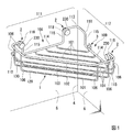
図1に示すように、収納用具本体1と、左壁5に左右に離間して水平に固定された2つの係合部2と、右壁6へ左壁5の係合部2と同じ高さに固定された1つの係合部2が設けられ、この1つの係合部2が入隅4より離間した位置に固定されている。さらに、前記右壁6に固定された係合部2より若干下方で、且つ、右壁6の入隅4側に押さえ部3が固定されている。
Hereinafter, the first embodiment of the present invention will be described in detail with reference to the drawings.
The storage tool for mounting an inside corner wall of the present invention comprises a storage tool
As shown in FIG. 1, the storage tool
本実施形態の収納用具本体1は、図1に示す様に、外周枠110と底部120と中枠130を有し、各々がステンレス鋼棒などの金属線材の折り曲げ加工と溶接により一体構成されており、平面視略五角形に形成されている。尚、平面視の形状は略扇型・略三角形・略四角形など、目的の収納物品の形状に合わせて適時採用することができる。
As shown in FIG. 1, the storage tool
収納用具本体1の外周枠110において、図1に示す様に、外周枠左側後部111の両端より内側の部分を下方に屈曲して凹部108が形成され、この凹部108の底部に位置する外周枠下部114と、凹部108の内側部に位置する外周枠縦延出部115が形成されている。
また、外周枠右側後部112も同様に凹部109が形成され、外周枠下部114と外周枠縦延出部115が形成されている。
As shown in FIG. 1, in the outer
Similarly, a
凹部108の左右の外周枠縦延出部115から外側に延出される部分には側面視倒L型あるいは逆L型の下方屈曲部118が形成されている。
外周枠左側後部111と外周枠右側後部112は、平面視L型に配置され、外周枠左側後部111と外周枠右側後部112の接合部分に外周枠入隅部113が形成され、この外周枠入隅部113が入隅4の直前に配置されている。
A downwardly bent L-shaped or inverted-L-shaped
The outer peripheral frame left
外周枠左側後部111と外周枠右側後部112を接続した外周枠入隅部113を外周枠左側後部111の基端側および外周枠右側後部112の基端側とすると、外周枠左側後部111と外周枠右側後部112の間にはこれらの基端側から先端側にかけて金属線材からなる支持ロッド101が所定間隔で複数水平に設けられている。
これらの支持ロッド101は、外周枠左側後部111と外周枠右側後部112に対し約45度の傾斜角度を有するように、その両端部を外周枠左側後部111の外周枠下部114と外周枠右側後部112の外周枠下部114に接続するように設けられている。これらの支持ロッド101は、各々の両端部を外周枠左側後部111の外周枠下部114と外周枠右側後部112の外周枠下部114に溶接し一体化されている。
Assuming that the outer
Both ends of the
外周枠左側後部111の左側端部と外周枠右側後部112の右側端部は前記支持ロッド101と略同等方向に延在する前端上部枠102で接続されており、その下方に前端中枠103が設けられている。
この前端中枠103は、外周枠左側後部111の左側端部と外周枠右側後部112の右側端部から垂下された縦延出片106によって両端を支持されている。また、縦延出片106の下端部には水平方向に延出された支持ロッド101が形成され、この支持ロッド101は他の支持ロッド101と平行に延在されている。
The left end of the outer frame left
The front end
前側上部枠102の中央部は支持ロッド101と平行に延在されているが、両端側は折曲されて外周枠左側後部111の左側端部と外周枠右側後部112の右側端部に一体化されている。これらの折曲部にも縦延出片106が2本間隔をあけて垂下され、これらの縦延出片106の下端部にも水平方向に延出された支持ロッド101が形成されている。
The center of the front
収納用具本体1において、外周枠左側後部111と外周枠右側後部112に対し約45度の傾斜角度で延在された複数本の支持ロッド101により収納用具本体1の底部120が構成されている。これら支持ロッド101により構成される底部120が後述する収納物品7の載置部となる。
また、収納用具本体1において、前端に位置する前端上部枠102と前端中枠103が後述する収納物品7の倒れ止めとなっている。
In the storage tool
Further, in the storage tool
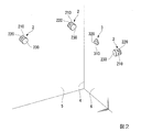
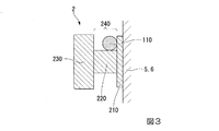
左壁5と右壁6に取り付けられている係合部2は、図2、図3に示す様に、壁面に接して固定される円板状の係合突き当て部210と、外周枠110を受ける柱状の係合支持部220と、係合支持部220の前方に設けた係合蓋230で構成されている。係合支持部220の上方に外周枠110と嵌合する係合溝240が形成されている。
As shown in FIGS. 2 and 3, the engaging
押さえ部3は図2に示す様に、壁面に接する円板状の押さえ突き当て部310と、この押さえ突き当て部310から直角に突出する円柱状の押さえ支持部320で構成されている。押さえ支持部320の突出寸法は、外周枠110の断面外寸(外周枠110を構成する金属線材の横断面外径)に対して1倍〜2倍程度に設定することで、取付け取外し動作に影響を与えず、尚且つ、収納用具本体1を確実に押さえることができる。
As shown in FIG. 2, the
図2に示す様に、係合部2及び押さえ部3は壁面に点在して配置されており、左壁5、右壁6を室内側より覆い隠す面積が少なく、収納用具本体1の取付け箇所の清掃性を極力損なうことがない。
As shown in FIG. 2, the engaging
図3に示す様に、外周枠110を構成する金属線材の断面外寸に対して係合溝240の幅の寸法(係合蓋230と係合突き当て部210の間の距離)を2倍程度、例えば、1.5倍〜3倍に設定することで、図4、図5に示す様に収納用具本体1の着脱を容易に行うことができる。
As shown in FIG. 3, the dimension of the width of the engagement groove 240 (the distance between the
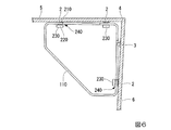
さらに、室内の入隅4の角度がかならずしも直角ではなく鋭角や鈍角に建て付けられる場合であっても、図6、図7に示す様に、係合溝240の幅寸法に余裕を持たせることで、収納用具本体1の着脱を可能とすることができる。
Further, even when the angle of the
係合部2及び押さえ部3の左壁5及び右壁6への固定は、係合突き当て部210及び押さえ突き当て部310を壁面にビス止めするか、あるいは、かしめ固定(図示せず)するなどの手段により行うことができる。勿論、壁面に対しビス止めするか、あるいは、かしめ固定するという以外の従来公知の方法、例えば、接着等の方法で係合突き当て部210及び押さえ突き当て部310を壁面に固定しても良く、これらの固定方法に特に制限はない。
The fixing of the engaging
収納用具本体1を入隅4を形成する左壁5と右壁6に固定された係合部2及び押さえ部3への着脱方法について、図4、図5を用いて以下に説明する。
まず、収納用具本体1の向かって左側を持ち上げた状態で、右壁6に固定された係合部2の係合溝240に、外周枠右側後部112の入隅4より離隔した下方屈曲部118を軽く載せ、次に収納用具本体1を略円弧状の軌跡で下方へ降ろし、左壁5に固定された係合部2の係合溝240に外周枠左側後部111の左右の下方屈曲部118を係合する。
A method for attaching and detaching the storage tool
First, with the left side lifted toward the
図4はその途中の状態を示す。外周枠左側後部111の右側の下方屈曲部118を左壁5の右側の係合部2の直上に位置させ、外周枠左側後部111の左側の下方屈曲部118を左壁5の左側の係合部2より若干上方に位置するまで収納用具本体1を略円弧状の軌跡に沿って下方へ降ろした状態を示している。
この状態から略円弧状の軌跡に沿って更に下方へ収納用具本体1を降ろして図1に示すように水平向きに位置を修正すると、外周枠左側後部111の左側の下方屈曲部118の直下に接合部2を嵌合できる。同時に、外周枠下部114が押さえ部3の下面側に当接するので収納用具本体1の位置決めを完了でき、収納用具本体1を入り隅4に取付けることができる。
FIG. 4 shows a state in the middle. The right lower
When the storage tool
また、逆の手順で収納用具本体1を入隅4から取外すことができる。
なお、本実施形態は右壁6に押さえ部3を設けたが、配置を左右勝手違いとして左壁5に接合部2と押さえ部3を配置し、右壁6に2つの接合部2を設けても構わない。
Further, the storage tool
In the present embodiment, the holding
収納用具本体1の着脱による左壁5、右壁6への傷付きを、係合突き当て部210と押さえ突き当て部310を設けることで抑制することができる。即ち、係合溝240の壁側に係合支持部220の径よりも径の大きな係合突き当て部210と押さえ突き当て部310を設けている。このため、取り付け、取り外しの際、収納用具本体1が係合突き当て部210と押さえ突き当て部310には接触したり、擦ることがあっても、壁面に当たったり、壁面を擦ることを抑制できるため、壁面の傷付きや壁面への汚れ付着を防止できる。
Damage to the
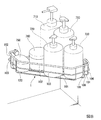
図8は、収納用具本体1に収納物品7である各種ボトル類やソープケースを収納した使用状態を示す。一例として、710はボディソープボトル、720はシャンプーボトル、730はトリートメントボトル、740はヘアパックケース、750は石鹸箱を示している。
FIG. 8 shows a usage state in which various bottles and a soap case, which are stored articles 7, are stored in the storage tool
図8に示すように、収納用具本体1の底部120を構成する複数の支持ロッド101上に収納物品7である各種ボトル類を載置することができる。また、収納用具本体1の前端側に前端上部枠102と前端中枠103を設けているので収納した各種ボトル類の前方側への転倒を防止できる。
As shown in FIG. 8, various bottles as storage articles 7 can be placed on a plurality of
図9は、収納用具本体1を、係合部2だけを用いて入り隅4に取付けた状態を示す。
収納用具本体1に収納物品7を収納した場合、外周枠前部116に手を掛けたなどの場合、外周枠前部116に上方からの押下力が作用するので、外周枠入隅部113の上方への跳ね上がり、さらには収納用具本体1が脱落する虞がある。
FIG. 9 shows a state in which the storage tool
When the storage article 7 is stored in the storage tool
そこで図1に示す様に、外周枠下部114の外周枠入隅部113側に上方に押さえ部3を設けることで、外周枠入隅部113が上方に跳ね上がることを防止できる。
従って、収納用具本体1に収納物品7を収納した場合、外周枠前部116に手を掛けたなどの場合であっても、外周枠入隅部113の上方への跳ね上がりを防止でき、収納用具本体1の脱落を防止でき、収納物品7の脱落を防止できる。
Therefore, as shown in FIG. 1, by providing the holding
Accordingly, even when the storage article 7 is stored in the storage tool
また、係合部2に係合蓋230を設けることで、収納用具本体1が入隅4から離れる方向への水平移動を抑制すると共に、外周枠縦延出部115により水平方向の移動も制限することができる。
In addition, by providing the engaging
1…収納用具本体、101…支持ロッド、102…前端上部枠、103…前端中枠、106…縦延出部、108、109…凹部、110…外周枠、111…外周枠左側後部、
112…外周枠右側後部、113…外周枠入隅部、114…外周枠下部、
115…外周枠縦延出部、116…外周枠前部、117…外周枠側部、
118…下方屈曲部、119…側方屈曲部、
120…底部、130…中枠、
2…係合部、210…係合突き当て部、220…係合支持部、230…係合蓋、240 …係合溝、
3…押さえ部、310…押さえ突き当て部、320…押さえ支持部、
4…入隅、5…左壁、6…右壁、
7…収納物品、710…ボディソープボトル、720…シャンプーボトル、730…トリートメントボトル、740…ヘアパックケース、750…石鹸箱。
DESCRIPTION OF
112: right rear part of the outer peripheral frame, 113: corner part of the outer peripheral frame, 114: lower part of the outer peripheral frame
115 ... outer peripheral frame vertical extension part, 116 ... outer peripheral frame front part, 117 ... outer peripheral frame side part,
118: downward bent portion, 119: side bent portion,
120: bottom, 130: middle frame,
2 ... engaging part, 210 ... engaging butting part, 220 ... engaging support part, 230 ... engaging lid, 240 ... engaging groove,
3 ... holding part, 310 ... holding butting part, 320 ... holding supporting part,
4 ... In corner, 5 ... Left wall, 6 ... Right wall,
7: stored articles, 710: body soap bottle, 720: shampoo bottle, 730: treatment bottle, 740: hair pack case, 750: soap box.
Claims (4)
前記外周枠が、前記入隅部の左壁に沿って横向きに延在される外周枠左側後部と、前記入隅部の右壁に沿って横向きに延在される外周枠右側後部と、前記外周枠左側後部の左右両端および前記外周枠右側後部の左右両端よりそれぞれ内側の位置より下方に延設された外周枠縦延出部と、前記外周枠縦延出部の下側に形成された外周枠下部を具備し、
前記左右の内壁の一方に同一高さ位置に離間して設けた2個の係合部と、前記左右の内壁の他方に前記係合部と同一高さ位置であって前記入隅から離間させて設けた1個の係合部と、前記左右の内壁の他方に前記係合部より下方の高さ位置で前記入隅側に設けた押さえ部を設けたことを特徴とする入隅壁面取付用収納用具の取付構造。 A storage tool having a storage tool main body having an outer peripheral frame and a bottom disposed at a corner of an inner wall in a room, an engaging portion for receiving the storage tool main body from below, and a holding section for pressing the storage tool main body from above. At
The outer peripheral frame, the outer peripheral frame left rear portion extending laterally along the left wall of the inset corner, and the outer peripheral frame right rear portion extending laterally along the right wall of the inset corner, The outer peripheral frame is formed below the left and right ends of the left rear portion of the outer peripheral frame and the left and right ends of the right rear portion of the outer peripheral frame. Equipped with a lower peripheral frame,
Two engaging portions provided on one of the left and right inner walls at the same height and separated from each other, and the other of the left and right inner walls at the same height as the engaging portion and separated from the corner. A mounting portion provided on one of the left and right inner walls, and a holding portion provided on the inside corner at a height lower than the engagement portion on the other of the left and right inner walls. Mounting structure for storage tools.
Priority Applications (1)
| Application Number | Priority Date | Filing Date | Title |
|---|---|---|---|
| JP2018132603A JP7144223B2 (en) | 2018-07-12 | 2018-07-12 | Mounting structure of the storage tool for mounting on the inner corner wall surface |
Applications Claiming Priority (1)
| Application Number | Priority Date | Filing Date | Title |
|---|---|---|---|
| JP2018132603A JP7144223B2 (en) | 2018-07-12 | 2018-07-12 | Mounting structure of the storage tool for mounting on the inner corner wall surface |
Publications (2)
| Publication Number | Publication Date |
|---|---|
| JP2020006103A true JP2020006103A (en) | 2020-01-16 |
| JP7144223B2 JP7144223B2 (en) | 2022-09-29 |
Family
ID=69149892
Family Applications (1)
| Application Number | Title | Priority Date | Filing Date |
|---|---|---|---|
| JP2018132603A Active JP7144223B2 (en) | 2018-07-12 | 2018-07-12 | Mounting structure of the storage tool for mounting on the inner corner wall surface |
Country Status (1)
| Country | Link |
|---|---|
| JP (1) | JP7144223B2 (en) |
Citations (3)
| Publication number | Priority date | Publication date | Assignee | Title |
|---|---|---|---|---|
| JPS63146534U (en) * | 1987-03-16 | 1988-09-27 | ||
| JP2016047119A (en) * | 2014-08-27 | 2016-04-07 | 株式会社ハウステック | Arrangement fixture for wall face installation |
| JP2018089175A (en) * | 2016-12-05 | 2018-06-14 | 株式会社Lixil | shelf |
-
2018
- 2018-07-12 JP JP2018132603A patent/JP7144223B2/en active Active
Patent Citations (3)
| Publication number | Priority date | Publication date | Assignee | Title |
|---|---|---|---|---|
| JPS63146534U (en) * | 1987-03-16 | 1988-09-27 | ||
| JP2016047119A (en) * | 2014-08-27 | 2016-04-07 | 株式会社ハウステック | Arrangement fixture for wall face installation |
| JP2018089175A (en) * | 2016-12-05 | 2018-06-14 | 株式会社Lixil | shelf |
Also Published As
| Publication number | Publication date |
|---|---|
| JP7144223B2 (en) | 2022-09-29 |
Similar Documents
| Publication | Publication Date | Title |
|---|---|---|
| JP2014500770A (en) | Drawer side wall with inner and outer walls | |
| JP2020006103A (en) | Attachment structure for storage tool for attaching to internal corner wall surface | |
| JP6562538B2 (en) | Desk equipment | |
| KR101188703B1 (en) | Coupling structures of bed frame | |
| JP2006266016A (en) | Mounting tool for window grille and window grille unit including the same | |
| JP2008008062A (en) | Sink stand mounting structure | |
| JP3153838U (en) | Simple detachable structure of standing object and support base | |
| JP6193706B2 (en) | Chair leg ends | |
| JP5965589B2 (en) | Storage rack and sink for mounting the storage rack | |
| JP4729335B2 (en) | Base cabinet and piping inspection port cover | |
| KR100889471B1 (en) | A corner rack | |
| JP4165962B2 (en) | Shelf unit | |
| JPS6227833Y2 (en) | ||
| JP3089146U (en) | Tool storage box structure with magnet | |
| JP2017202018A (en) | Mop storage container | |
| JP2014018613A (en) | Device and method for holding tabular member | |
| JP2509373Y2 (en) | Scaffolding board | |
| JP7301328B2 (en) | frame rack | |
| JP3500978B2 (en) | Mounting structure for hanging shelves | |
| JP4377201B2 (en) | table | |
| JPH0119886Y2 (en) | ||
| JP2008290752A (en) | Folding container | |
| JP4663411B2 (en) | Dishwasher | |
| JP3177092U (en) | Hook for furniture | |
| JP2005137710A (en) | Table |
Legal Events
| Date | Code | Title | Description |
|---|---|---|---|
| A80 | Written request to apply exceptions to lack of novelty of invention |
Free format text: JAPANESE INTERMEDIATE CODE: A80 Effective date: 20180808 |
|
| A621 | Written request for application examination |
Free format text: JAPANESE INTERMEDIATE CODE: A621 Effective date: 20210510 |
|
| A977 | Report on retrieval |
Free format text: JAPANESE INTERMEDIATE CODE: A971007 Effective date: 20220311 |
|
| A131 | Notification of reasons for refusal |
Free format text: JAPANESE INTERMEDIATE CODE: A131 Effective date: 20220322 |
|
| A521 | Request for written amendment filed |
Free format text: JAPANESE INTERMEDIATE CODE: A523 Effective date: 20220518 |
|
| TRDD | Decision of grant or rejection written | ||
| A01 | Written decision to grant a patent or to grant a registration (utility model) |
Free format text: JAPANESE INTERMEDIATE CODE: A01 Effective date: 20220823 |
|
| A61 | First payment of annual fees (during grant procedure) |
Free format text: JAPANESE INTERMEDIATE CODE: A61 Effective date: 20220915 |
|
| R150 | Certificate of patent or registration of utility model |
Ref document number: 7144223 Country of ref document: JP Free format text: JAPANESE INTERMEDIATE CODE: R150 |