JP2020004268A - Image processing device, image processing method, and program - Google Patents
Image processing device, image processing method, and program Download PDFInfo
- Publication number
- JP2020004268A JP2020004268A JP2018125284A JP2018125284A JP2020004268A JP 2020004268 A JP2020004268 A JP 2020004268A JP 2018125284 A JP2018125284 A JP 2018125284A JP 2018125284 A JP2018125284 A JP 2018125284A JP 2020004268 A JP2020004268 A JP 2020004268A
- Authority
- JP
- Japan
- Prior art keywords
- dynamic range
- image data
- conversion
- luminance
- image processing
- Prior art date
- Legal status (The legal status is an assumption and is not a legal conclusion. Google has not performed a legal analysis and makes no representation as to the accuracy of the status listed.)
- Granted
Links
- 238000012545 processing Methods 0.000 title claims abstract description 107
- 238000003672 processing method Methods 0.000 title description 3
- 238000006243 chemical reaction Methods 0.000 claims abstract description 70
- 238000007639 printing Methods 0.000 claims abstract description 40
- 238000000034 method Methods 0.000 claims description 52
- 238000012937 correction Methods 0.000 claims description 16
- 238000005286 illumination Methods 0.000 claims description 14
- 230000002194 synthesizing effect Effects 0.000 claims description 3
- 239000000463 material Substances 0.000 claims description 2
- 238000007906 compression Methods 0.000 description 27
- 230000006835 compression Effects 0.000 description 24
- 238000011161 development Methods 0.000 description 10
- 238000000926 separation method Methods 0.000 description 10
- 238000012546 transfer Methods 0.000 description 9
- 230000015572 biosynthetic process Effects 0.000 description 7
- 238000003786 synthesis reaction Methods 0.000 description 7
- 238000003384 imaging method Methods 0.000 description 5
- 238000010586 diagram Methods 0.000 description 4
- 230000006870 function Effects 0.000 description 4
- 230000000694 effects Effects 0.000 description 3
- 241000533901 Narcissus papyraceus Species 0.000 description 2
- 230000002411 adverse Effects 0.000 description 2
- 230000007423 decrease Effects 0.000 description 2
- 238000009792 diffusion process Methods 0.000 description 2
- 230000010365 information processing Effects 0.000 description 2
- 238000012552 review Methods 0.000 description 2
- 229920006395 saturated elastomer Polymers 0.000 description 2
- 230000000007 visual effect Effects 0.000 description 2
- 238000013459 approach Methods 0.000 description 1
- 238000005452 bending Methods 0.000 description 1
- 230000000740 bleeding effect Effects 0.000 description 1
- 238000004364 calculation method Methods 0.000 description 1
- 239000003086 colorant Substances 0.000 description 1
- 238000004891 communication Methods 0.000 description 1
- 230000006866 deterioration Effects 0.000 description 1
- 238000005516 engineering process Methods 0.000 description 1
- 238000001914 filtration Methods 0.000 description 1
- 125000001475 halogen functional group Chemical group 0.000 description 1
- 238000010191 image analysis Methods 0.000 description 1
- 238000013507 mapping Methods 0.000 description 1
- 239000011159 matrix material Substances 0.000 description 1
- 238000005457 optimization Methods 0.000 description 1
- 230000002250 progressing effect Effects 0.000 description 1
Images


Classifications
-
- H—ELECTRICITY
- H04—ELECTRIC COMMUNICATION TECHNIQUE
- H04N—PICTORIAL COMMUNICATION, e.g. TELEVISION
- H04N1/00—Scanning, transmission or reproduction of documents or the like, e.g. facsimile transmission; Details thereof
- H04N1/46—Colour picture communication systems
- H04N1/56—Processing of colour picture signals
- H04N1/60—Colour correction or control
- H04N1/6002—Corrections within particular colour systems
- H04N1/6005—Corrections within particular colour systems with luminance or chrominance signals, e.g. LC1C2, HSL or YUV
-
- H—ELECTRICITY
- H04—ELECTRIC COMMUNICATION TECHNIQUE
- H04N—PICTORIAL COMMUNICATION, e.g. TELEVISION
- H04N1/00—Scanning, transmission or reproduction of documents or the like, e.g. facsimile transmission; Details thereof
- H04N1/46—Colour picture communication systems
- H04N1/56—Processing of colour picture signals
- H04N1/60—Colour correction or control
- H04N1/6027—Correction or control of colour gradation or colour contrast
-
- H—ELECTRICITY
- H04—ELECTRIC COMMUNICATION TECHNIQUE
- H04N—PICTORIAL COMMUNICATION, e.g. TELEVISION
- H04N1/00—Scanning, transmission or reproduction of documents or the like, e.g. facsimile transmission; Details thereof
- H04N1/46—Colour picture communication systems
- H04N1/56—Processing of colour picture signals
- H04N1/60—Colour correction or control
- H04N1/6002—Corrections within particular colour systems
- H04N1/6008—Corrections within particular colour systems with primary colour signals, e.g. RGB or CMY(K)
-
- H—ELECTRICITY
- H04—ELECTRIC COMMUNICATION TECHNIQUE
- H04N—PICTORIAL COMMUNICATION, e.g. TELEVISION
- H04N1/00—Scanning, transmission or reproduction of documents or the like, e.g. facsimile transmission; Details thereof
- H04N1/46—Colour picture communication systems
- H04N1/56—Processing of colour picture signals
- H04N1/60—Colour correction or control
- H04N1/6083—Colour correction or control controlled by factors external to the apparatus
- H04N1/6086—Colour correction or control controlled by factors external to the apparatus by scene illuminant, i.e. conditions at the time of picture capture, e.g. flash, optical filter used, evening, cloud, daylight, artificial lighting, white point measurement, colour temperature
-
- H—ELECTRICITY
- H04—ELECTRIC COMMUNICATION TECHNIQUE
- H04N—PICTORIAL COMMUNICATION, e.g. TELEVISION
- H04N1/00—Scanning, transmission or reproduction of documents or the like, e.g. facsimile transmission; Details thereof
- H04N1/46—Colour picture communication systems
- H04N1/56—Processing of colour picture signals
- H04N1/60—Colour correction or control
- H04N1/6097—Colour correction or control depending on the characteristics of the output medium, e.g. glossy paper, matt paper, transparency or fabrics
Abstract
Description
本発明は、画像処理装置、画像処理方法、及びプログラムに関する。 The present invention relates to an image processing device, an image processing method, and a program.
昨今のデジタルカメラでは、高輝度な表示装置などへの撮影画像の出力のため、輝度のレンジ(以下、ダイナミックレンジ)が広い撮像ができるようになってきている。デジタルカメラにおいて、光を信号に変換するセンサーは、より多くの光を受光可能なように構成されることで、これまでは信号値が飽和し、高輝度部で白くなっていた領域(白飛び部)の再現が可能になってきている。 2. Description of the Related Art In recent digital cameras, an image with a wide luminance range (hereinafter, dynamic range) can be captured in order to output a captured image to a high-luminance display device or the like. In a digital camera, a sensor that converts light into a signal is configured to be able to receive more light, so that the signal value has been saturated and a white area in a high-luminance part (whiteout). Part) can be reproduced.
また、画像処理によって、高輝度側の再現性を拡張する方法が提案されている。特許文献1では、特定の色で飽和した高輝度部に対し、画像の解析結果に基づき、階調再現を実現している。このようにデバイスの性能向上と画像処理の両者の点から、撮影画像データのダイナミックレンジを広げる方法が提案されている。
Further, a method of extending the reproducibility on the high luminance side by image processing has been proposed. In
こうした状況の中、最適な印刷画質を実現するには、入力画像が有するダイナミックレンジ、および出力側のダイナミックレンジを考慮し、適切に処理を行う必要がある。一般的には出力側のダイナミックレンジに比べ、入力側のダイナミックレンジが広い場合が多く、入力画像に対して誤った処理を施してしまうと、明るさが極端に異なる画質になったり、コントラストの低い画質になったり、といった画像弊害が生じてしまう。 Under these circumstances, in order to realize the optimum print quality, it is necessary to perform appropriate processing in consideration of the dynamic range of the input image and the dynamic range of the output side. In general, the dynamic range on the input side is often wider than the dynamic range on the output side, and if erroneous processing is performed on the input image, the image quality will be extremely different in brightness, An image problem such as a low image quality occurs.
特許文献2においては、画像のコントラストを補正する処理として、画像を照明光成分および反射率成分に分離し、コントラスト補正を実施するRetinex理論に基づいた処理が開示されている。非特許文献1では、Retinex理論にさらに領域ごとに適したマッピングカーブを作成する技術が開示されている。
Patent Literature 2 discloses a process based on the Retinex theory for separating an image into an illumination light component and a reflectance component and performing contrast correction, as a process for correcting the contrast of the image. Non-Patent
写真印刷において、使用する印刷用紙の多様化が進んでいる。単に写真画像を印刷するだけでなく、撮影した被写体や印刷した写真画像の見せ方などを考慮し、様々な特性を有する用紙(種類やサイズなど)を選択することが可能となってきている。画像を再現できるダイナミックレンジは、用紙の種類により変化し、さらに印刷物を観察する環境においても変化する。例えば、光沢紙は、表面の光沢特性が低いマットな紙に比べ、黒濃度が高く、再現できるダイナミックレンジが一般的に広い。また、照明などを当てて観察する展示会や個展、ギャラリーなどの場合は、その照明効果により、印刷物のダイナミックレンジは広がることになる。 In photo printing, diversification of printing paper to be used is progressing. In addition to simply printing a photographic image, it is becoming possible to select paper (type, size, etc.) having various characteristics in consideration of a photographed subject, how to display the printed photographic image, and the like. The dynamic range in which an image can be reproduced changes depending on the type of paper, and also changes in an environment in which a printed matter is observed. For example, glossy paper has a higher black density and generally has a wider reproducible dynamic range than matte paper having low glossiness on the surface. In addition, in the case of exhibitions, solo exhibitions, galleries, and the like, which are observed with illumination or the like, the dynamic range of the printed matter is expanded by the illumination effect.
上記先行技術の処理を適用して印刷を行ったとしても、印刷用紙が有する特性を考慮しないと、適切な出力のダイナミックレンジが求められず、その結果、好適な印刷物を得ることができない。また、用紙種類以外にも、ダイナミックレンジに影響を及ぼすものとして、印刷物の観察環境が考慮されていないと適切な印刷物を実現できない。つまり、撮影画像を用いた印刷物の印刷情報を考慮していない場合には、適切な明るさの画像の印刷物を生成することができない。 Even if printing is performed by applying the processing of the above-mentioned prior art, an appropriate output dynamic range cannot be obtained unless the characteristics of the printing paper are taken into consideration, and as a result, a suitable printed matter cannot be obtained. Further, besides the type of paper, an appropriate printed matter cannot be realized unless the observation environment of the printed matter is taken into consideration as affecting the dynamic range. That is, unless the print information of the printed matter using the photographed image is taken into consideration, a printed matter of an image having an appropriate brightness cannot be generated.
上記課題を解決するために本願発明は以下の構成を有する。すなわち、画像処理装置であって、撮影画像データのダイナミックレンジを取得する取得手段と、印刷情報に基づいて、前記撮影画像データに対する印刷時のダイナミックレンジを決定する決定手段と、前記撮影画像データの輝度に対し、前記取得手段にて取得されたダイナミックレンジから前記決定手段にて決定されたダイナミックレンジへの変換処理を行う変換手段とを有する。 In order to solve the above problems, the present invention has the following configuration. That is, an image processing apparatus, an acquisition unit that acquires a dynamic range of captured image data, a determination unit that determines a dynamic range at the time of printing on the captured image data based on print information, Conversion means for converting the luminance from the dynamic range obtained by the obtaining means to the dynamic range determined by the determining means.
本発明によれば、印刷用紙の特性や印刷物の観察環境などの印刷に関する情報を考慮した、適切な明るさの印刷物を実現することができる。 ADVANTAGE OF THE INVENTION According to this invention, the printed matter of suitable brightness can be implement | achieved in consideration of the information regarding printing, such as the characteristic of a printing paper and the observation environment of a printed matter.
<第1の実施形態>
[システム構成]
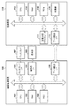
図1は、本実施形態を適用可能なシステムの構成例を示す図である。本実施形態において、システムは、画像処理装置100と記録装置110を含んで構成される。画像処理装置100は、情報処理装置として機能するホストPCなどから構成される。画像処理装置100は、CPU101、RAM102、HDD103、ディスプレイI/F104、操作部I/F105、およびデータ転送I/F106を含んで構成され、各部位は内部バスを介して通信可能に接続されている。
<First embodiment>
[System configuration]
FIG. 1 is a diagram illustrating a configuration example of a system to which the present embodiment can be applied. In the present embodiment, the system includes the
CPU101は、HDD103に保持されるプログラムに従ってRAM102をワークエリアとして用いて各種処理を実行する。RAM102は、揮発性の記憶領域であり、ワームメモリ等として利用される。HDD103は、不揮発性の記憶領域であり、本実施形態に係るプログラムやOS(Operating System)などが保持される。ディスプレイI/F104は、ディスプレイ107と画像処理装置100本体との間でデータの送受信を行うためのインターフェースである。操作部I/F105は、キーボードやマウスなどの操作部108を用いて入力された指示を画像処理装置100本体に入力するためのインターフェースである。データ転送I/F106は、外部装置とのデータの送受信を行うためのインターフェースである。
The
例えば、CPU101は、操作部108を用いたユーザによる指示(コマンド等)やHDD103に保持されるプログラムに従って記録装置110が記録可能な画像データを生成し、これを記録装置110に転送する。また、CPU101は、データ転送I/F106を介して外部装置から受信した画像データに対し、HDD103に記憶されているプログラムに従って所定の処理を行い、その結果や様々な情報をディスプレイ107に表示する。
For example, the
記録装置110は、画像処理アクセラレータ111、データ転送I/F112、CPU113、RAM114、ROM115、および印刷部116を含んで構成され、各部位は内部バスを介して通信可能に接続されている。なお、記録装置110の記録方式は特に限定するものでは無く、例えば、インクジェット方式の記録装置であってもよいし、電子写真方式の記録装置であってもよい。以下では、インクジェット方式の記録装置を例に挙げて説明する。
The
CPU113は、ROM115に保持されるプログラムに従ってRAM114をワークエリアとして用いて各種処理を実行する。RAM114は、揮発性の記憶領域であり、ワークメモリ等として利用される。ROM115は、不揮発性の記憶領域であり、本実施形態に係るプログラムやOS(Operating System)などが保持される。データ転送I/F112は、外部装置とのデータの送受信を行うためのインターフェースである。画像処理アクセラレータ111は、CPU113よりも高速に画像処理を実行可能なハードウェアである。画像処理アクセラレータ111は、CPU113が画像処理に必要なパラメータとデータをRAM114の所定のアドレスに書き込むことにより起動され、上記パラメータとデータを読み込んだ後、上記データに対し所定の画像処理を実行する。但し、画像処理アクセラレータ111は必須な要素ではなく、同等の処理はCPU113でも実行することができる。印刷部116は、画像処理装置100からの指示に基づき、印刷動作を行う。
The
画像処理装置100のデータ転送I/F106および記録装置110のデータ転送I/F112における接続方式は、特に限定するものではなく、例えば、USB(Universal Serial Bus)、IEEE1394等を用いることができる。また、有線/無線も問わない。
The connection method in the data transfer I /
[処理ブロック]
図2は、本実施形態に係る画像処理装置100で実行される画像処理の処理ブロックを示す。本実施形態において、各処理ブロックに対応するプログラムが、アプリケーション200に含まれるように構成された例にて説明する。アプリケーション200は、情報処理装置としての画像処理装置100にて動作し、CPU101にて対応するプログラムが読み出されることで実行される。なお、アプリケーション200は、一つのアプリケーションである必要はなく、ユーザの用途や機能に応じ、複数のアプリケーションにて構成されるような形態であってもよい。また、一部の処理を、カメラ等の撮影装置(不図示)もしくは記録装置110側に組み込み、これらにて実現されるような構成であってもよい。
[Processing block]
FIG. 2 shows processing blocks of image processing executed by the
画像取得部201は、処理対象の画像データを取得する。取得方法は、撮影を行った撮影装置(不図示)の情報と合わせてHDD103に保持されている画像データを取得するような構成でもよい。もしくは、外部装置(例えば、撮影装置)からデータ転送I/F106を介して撮影画像データを取得するような構成でもよい。現像部202は、画像取得部201で取得した画像を後述する処理により、所定の形式に変換する。画像データが有するダイナミックレンジの算出も現像部202で行われ、求められた値はダイナミックレンジ取得部205へと出力される。
The
用紙情報取得部203は、ユーザの指示や設定等に従って、印刷に用いられる用紙の情報を取得し、ダイナミックレンジ取得部205へ提供する。ここで、記録装置110が対応可能な用紙の情報は、記録装置110に問い合わせた上で、取得してもよいし、予めHDD103等に保持していてもよい。観察環境取得部204は、ユーザの指示や設定等に従って、印刷物が観察される環境に対応する情報を取得し、ダイナミックレンジ取得部205へ提供する。ここで取得される用紙情報や観察環境に関する情報については後述する。
The paper
ダイナミックレンジ取得部205は、各部位から出力された情報を取得し、取得した情報に基づいて入力と出力それぞれのダイナミックレンジを特定した上で、ダイナミックレンジ圧縮部208へと出力する。
The dynamic
輝度色差分離部206では、現像部202にて現像処理が行われた画像に対し、輝度と色差に分離する。輝度色差分離部206は、分離した輝度情報を周波数分離部207へ出力し、色差情報を輝度色差合成部211へ出力する。周波数分離部207は、画像の輝度情報に対し空間周波数の低周波と高周波に分離する。周波数分離部207は、分離された周波数のうち、低周波成分をダイナミックレンジ圧縮部208へ出力し、高周波成分をコントラスト補正部209へ出力する。ダイナミックレンジ圧縮部208は、ダイナミックレンジ取得部205で取得した値に基づき、周波数分離部207から取得した低周波成分に対しダイナミックレンジ圧縮処理を実行する。この際、ダイナミックレンジ圧縮部208は、現像部202からのデータを利用する。ダイナミックレンジ圧縮部208は、処理後のデータを周波数合成部210へ出力する。
The luminance / color
コントラスト補正部209は、周波数分離部207から取得した高周波成分に対してコントラスト補正処理を行う。コントラスト補正部209は、周波数毎にコントラスト補正処理を行った後、周波数合成部210へ結果を出力する。周波数合成部210は、ダイナミックレンジ圧縮部208とコントラスト補正部209から取得した周波数成分の合成を行い、輝度色差合成部211へ出力する。輝度色差合成部211は、周波数合成部210から取得した周波数と、輝度色差分離部206から取得した色差との合成を行う。そして、輝度色差合成部211は、合成により生成された画像情報を印刷処理部212へ出力する。
The
印刷処理部212は、輝度色差合成部211から取得された画像に対して印刷に要する処理を実行し、記録装置110へ送信する。このとき、用紙情報取得部203にて取得した用紙情報も併せて利用される。これにより、記録装置110側では、画像処理装置100にて処理が行われた印刷画像を用いた印刷物が出力される。
The
[画像処理フロー]
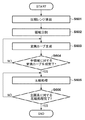
本実施形態に係る画像処理のフローについて、図3を用いて説明する。図3のフローチャートは、図2の各処理ブロックの動作に対応する。
[Image processing flow]
An image processing flow according to the present embodiment will be described with reference to FIG. The flowchart in FIG. 3 corresponds to the operation of each processing block in FIG.
S301にて、画像取得部201は、撮像装置(不図示)にて撮像された画像データを取得する。ここで取得する画像データは、JPEG形式などの汎用的なデータではなく、撮像装置(不図示)で撮像されたままのいわゆるRAWデータを用いる。これは、S302で実施される現像処理により、画像処理におけるダイナミックレンジの拡張を目的とするためである。
In S301, the
S302にて、現像部202は、現像処理を行う。図4に現像処理のフローチャートを示す。
In S302, developing
S401にて、現像部202は、色補間処理を行う。現像部202は、単色の信号で構成されたRAWデータ内の画素の各々に、デベイヤー処理またはモザイク処理を実施する。本処理により、各画素の信号値は、RGBの画像信号値へ変換される。色補間処理については公知の方法を用いるものとし、詳細な説明は省略する。
In S401, the developing
S402にて、現像部202は、ホワイトバランス調整を行う。現像部202は、予め設定された現像設定に従い、ホワイトバランス処理を行う。現像設定に対応する係数は、予め定義され、HDD103等にて保持されているものとする。現像部202は、画素のR,G,Bの各信号値に対し、設定された係数を乗じる。
In S402, developing
S403にて、現像部202は、ガンマ補正を行う。現像部202は、現像設定および記録装置の特性を考慮し、ガンマ補正を適用する。ガンマ補正については公知であるため、詳細な説明は省略する。
In S403, developing
S404にて、現像部202は、ノイズ除去を行う。S405にて、現像部202は、シャープネス処理を行う。本実施形態において、ノイズ除去およびシャープネス処理はいずれも、フィルタ処理により実施する。これらの処理の内容は、ユーザの設定や撮影条件に基づき、必要に応じて適用される。
In S404, developing
S406にて、現像部202は、色変換処理を行う。色変換処理として、定義された所定の色空間への変換や、色相の調整および高輝度領域の色曲りを抑圧する処理が行われる。そして、本処理フローを終了する。以上の現像処理により、所望のガンマ値を有するRGBの画像が生成される。
In S406, developing
図3の説明に戻る。S303にて、ダイナミックレンジ取得部205は、入力の明暗部それぞれの輝度データを取得する。明部の輝度データは、取得した画像データに含まれるカメラ情報および撮影時設定から算出される値と、S302の現像処理で拡張される値により求められる。具体的には、図4のS402のホワイトバランス調整の際、飽和レベルおよび画素情報に応じた置換処理を実施することで、高輝度領域の階調を拡張(N段:N≧1)する。本工程の処理は、例えば、特許文献1に開示されている方法を用いることが可能である。
Returning to the description of FIG. In S303, the dynamic
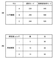
図5(a)は、本実施形態に係るカメラ情報および撮影時設定ごとの明部の輝度値の例を示す。カメラの機種に対する各撮影モードの輝度値が示されている。本実施形態では、3つのカメラ(撮像装置)の機種(A〜C)が示されている。また、各カメラが動作可能な撮影モードとして、通常モードと高輝度取得モードが示されている。高輝度取得モードは、一段分暗い露出条件で撮影を行う場合に用いられる撮影設定である。図5(a)に示されている輝度値Rは、高輝度部の輝度値(単位:%、測光した輝度を18%とした場合からの相対値)である。S302にて得られた、高輝度領域における拡張情報(N段分拡張可能)に基づき、最終的な入力画像の明部の輝度値Yi(W)は、下式から算出される。Nは、階調を拡張する段数を示す。
Yi(W)=R×2N ・・・(式1)
FIG. 5A shows an example of the camera information and the brightness value of the bright portion for each shooting setting according to the present embodiment. The luminance value of each shooting mode for the camera model is shown. In the present embodiment, models (A to C) of three cameras (imaging devices) are shown. Also, a normal mode and a high-luminance acquisition mode are shown as shooting modes in which each camera can operate. The high-brightness acquisition mode is a photographing setting used when photographing is performed under an exposure condition darker by one step. The luminance value R shown in FIG. 5A is a luminance value of a high luminance portion (unit:%, relative value from a case where the measured luminance is 18%). Based on the extended information in the high-luminance area (expandable by N steps) obtained in S302, the final luminance value Yi (W) of the bright part of the input image is calculated from the following equation. N indicates the number of stages for expanding the gradation.
Yi (W) = R × 2N (Equation 1)
入力画像の暗部輝度Yi(D)については、光が入らない場合を想定しているため、設定に依らず、Yi(D)=0となる。 Regarding the dark portion luminance Yi (D) of the input image, it is assumed that no light enters, and therefore Yi (D) = 0 regardless of the setting.
S304にて、ダイナミックレンジ取得部205は、出力側の明暗部それぞれの輝度データの取得を行う。図5(b)は、本実施形態に係る用紙種類毎の輝度値の例を示す。本実施形態では、3つの用紙種類が示されている。各用紙種類に対し、黒部Yо(D)と紙白部Yо(W)の輝度値を示す。輝度値[cd/m2]は、予め決められた一般的な照明環境の値(基準となる白≒100[cd/m2])である。なお、輝度値は、視覚特性を考慮した変換したものを使用してもよい。図5(b)に示される用紙情報は、用紙情報取得部203により提供される。
In S304, the dynamic
S305にて、輝度色差分離部206は、RGBの信号値から、輝度(Y)と色差(CbCr)の情報に分離を行う。RGB−YCbCr変換は、以下の式2により実施される。なお、変換式は、以下の式2に限定するものではなく、他の変換式を用いてもよい。
Y=0.29900×R+0.58700×G+0.11400×B
Cb=−0.16874×R−0.33126×G+0.50000×B ・・・(式2)
Cr=0.50000×R−0.41869×G−0.081×B
変換式にて得られたY値(輝度値)は、輝度成分としてS305の周波数分離処理にて用いられ、CbCr値は色差成分としてS310の輝度色差合成処理にて用いられる。
In S305, the luminance / color
Y = 0.29900 × R + 0.58700 × G + 0.11400 × B
Cb = −0.16874 × R−0.33126 × G + 0.50000 × B (Formula 2)
Cr = 0.50000 x R-0.41869 x G-0.081 x B
The Y value (luminance value) obtained by the conversion formula is used as a luminance component in the frequency separation process in S305, and the CbCr value is used as a color difference component in the luminance / color difference synthesis process in S310.
S306にて、周波数分離部207は、S305にて分離された画像の輝度の周波数を、低周波成分画像と高周波成分画像に分離する。本実施形態では、低周波成分を抽出するために、ローパスフィルタを適用する。処理方法は、空間フィルタを適用してもよいし、一旦、FFT(Fast Fourier Transform)により空間周波数に変換し、フィルタ処理後にIFFT(Inverse Fast Fourier Transform)で戻してもよい。対象とする周波数は、印刷物の用紙サイズや印刷物を観察する観察距離などから、人間の視覚特性を考慮し、決定してよい。したがって、周波数に含まれる高周波成分と、低周波成分はその分類が固定されたものではなく、上記基準に応じて変動してよい。高周波成分については、逆のハイパスフィルタを適用してもよいし、得られた低周波成分を元の画像から除算することで取得してもよい。ここで取得された低周波成分は、S307のダイナミックレンジ圧縮処理にて用いられ、高周波成分は、S308のコントラスト補正処理にて用いられる。
In S306,
S307にて、ダイナミックレンジ圧縮部208は、S303、S304にて取得した入力および出力の明暗部の情報に基づき、S306にて取得した低周波成分に対し、ダイナミックレンジ圧縮処理を行う。処理の詳細については図6を用いて後述する。
In S307, the dynamic
S308にて、コントラスト補正部209は、S306にて取得した高周波成分に対し、コントラスト補正処理を行う。具体的には、得られた画像に対し、係数kを乗じる。このとき、撮影時のシーンに近づける場合はk=1付近とし、さらに印刷物のインクの滲みなどの劣化を考慮したい場合は、1よりも大きい値を係数kに設定する。係数kの値は、ユーザの設定や指示に基づいて、値を変更できるような構成であってもよい。
In S308, the
S309にて、周波数合成部210は、S307にて得られた低周波成分でのダイナミックレンジ圧縮された画像と、S308にて得られた高周波成分でのコントラスト補正された画像の合成を行う。これにより、所定のダイナミックレンジに圧縮され、かつ、コントラスト補正がなされた輝度画像が得られる。
In S309, the
S310にて、輝度色差合成部211は、S310にて得られた輝度画像と、S305にて得られた色差成分とを合成し、下記式3を用いて、YCbCr−RGB変換を行う。これにより、RGB信号値の画像が得られる。式3は、式2に対応するものであり、式2とは異なる式が用いられていた場合には、これに合わせて式3も変化する。
R=Y+1.40200×Cr
G=Y−0.34414×Cb−0.71414×Cr ・・・(式3)
B=Y+1.77200×Cb
In S310, the luminance / color
R = Y + 1.40200 × Cr
G = Y−0.34414 × Cb−0.71414 × Cr (Equation 3)
B = Y + 1.77200 × Cb
S311にて、印刷処理部212は、得られたRGB信号値の画像に対し、印刷のための画像処理を行う。本工程の詳細については、図7を用いて後述する。そして、本処理フローを終了する。
In step S311, the
(ダイナミックレンジ圧縮処理)
本実施形態に係るダイナミックレンジ圧縮処理について、図6を用いて説明を行う。本工程は、図3のS307の処理に対応する。
(Dynamic range compression processing)
The dynamic range compression processing according to the present embodiment will be described with reference to FIG. This step corresponds to the process of S307 in FIG.
S601にて、ダイナミックレンジ圧縮部208は、図3のS303およびS304により得られた明暗部の情報から、圧縮レンジの算出を行う。圧縮レンジは、下式から求められる。Yi(W)、Yi(D)は、入力された撮影画像データから取得した入力の明暗部の輝度データを示す。Yо(W)、Yо(D)は、印刷用紙および観察環境より取得した出力の明暗部の輝度データを示す。
Di=Yi(W)−Yi(D) ・・・(式4)
Dо=Yо(W)−Yо(D) ・・・(式5)
Di、Dоはそれぞれ、入力、出力側のダイナミックレンジを表す。つまり、Diは、入力された画像データのダイナミックレンジであり、Doは、出力時(印刷時)に用いられるダイナミックレンジである。尚、図3に示すフローの説明の中で、入力の明暗部の単位は[%]とし、出力の明暗部の単位は[cd/m2]としたが、ここでは等価の変換可能であるとし、1%=1cd/m2とする。また、ダイナミックレンジ圧縮部208は、露出輝度値Yaの取得を行う。これは、撮影時にユーザが露出を設定した点であり、ここでは、露出設定輝度Ya=18[%]とする。
In S601, the dynamic
Di = Yi (W) −Yi (D) (Equation 4)
Do = Yo (W) -Yo (D) (Equation 5)
Di and Do represent the dynamic ranges on the input and output sides, respectively. That is, Di is the dynamic range of the input image data, and Do is the dynamic range used at the time of output (at the time of printing). In the description of the flow shown in FIG. 3, the unit of the light and dark part of the input is [%] and the unit of the light and dark part of the output is [cd / m 2 ], but equivalent conversion is possible here. 1% = 1 cd / m 2 . Further, the dynamic
S602にて、ダイナミックレンジ圧縮部208は、対象画像を所定の領域に分割する。ここでの分割は、予め決められた所定の矩形サイズで分割してもよいし、輝度画像の情報から類似の輝度画素でグルーピングしてもよい。後者の方法では、領域分割された特定の輝度レンジのコントラストを復元することになり、よりコントラストの保持された画像が得られる。さらに好適な印刷物を得るために、輝度データのみでなく、現像部202で現像されたRGBを利用してもよい。RGBデータより、画像の認識を行い、認識された領域種別に合ったコントラストの復元方法が可能となる。
In S602, dynamic
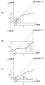
S603にて、ダイナミックレンジ圧縮部208は、S602で分割された領域それぞれに対し変換カーブを作成する。図8は、本実施形態に係る変換カーブの例を示す。変換カーブは、輝度の入力値と出力値との対応関係を示し、輝度値の変換に用いられる変換条件である。図8において、横軸は入力輝度を示し、縦軸は出力輝度を示す。また、破線は、原点を通る傾きが45度の直線を表し、太線は変換カーブを表す。図8において、棒グラフは、領域の輝度分布を示し、所定輝度範囲(以下、輝度グループ)の度数に相当する。輝度分布の度数(棒グラフ)に対応する値は、図8の右側に示す。S601で求められた入力および出力のダイナミックレンジDi、Doは、図8中の矢印で表される。
In step S603, the dynamic
変換カーブの傾きに着目する。傾きが1、つまり45度の場合は、その位置での画像変化が起きない。つまり、ダイナミックレンジ変換前のコントラストがダイナミックレンジ変換後も維持される。傾きが小さくなるにつれ(角度として45度未満)、変換後のコントラストは、変換前と比較して低下する。つまり、傾きが1に近いほど、変換前後のコントラストの変動が小さくなり、コントラストが維持される。好適な印刷物を得るには、コントラストの維持が必要であり、傾きを1に維持することが望ましい。ここで低周波成分を取り扱っているため、低周波成分のコントラストを維持するために、できる限りの傾きが1となるような変換を行う必要がある。 Focus on the slope of the conversion curve. If the inclination is 1, that is, 45 degrees, no image change occurs at that position. That is, the contrast before the dynamic range conversion is maintained after the dynamic range conversion. As the inclination decreases (the angle is less than 45 degrees), the contrast after conversion decreases as compared with before the conversion. In other words, as the inclination is closer to 1, the fluctuation of the contrast before and after the conversion becomes smaller, and the contrast is maintained. In order to obtain a suitable printed matter, it is necessary to maintain the contrast, and it is desirable to maintain the inclination at 1. Here, since low-frequency components are handled, it is necessary to perform conversion so that the gradient as much as possible becomes 1 in order to maintain the contrast of low-frequency components.
また、本実施形態において、黒濃度の低いマット系の用紙が用いられ、照明が印刷物に照射されていないことを想定する。このような用紙設定や観察環境などの設定は、画像処理を行う際に、ユーザにより指示もしくは設定されるものとする。したがって、画像処理装置100(アプリケーション200)は、ユーザが各設定を行うためのユーザーインターフェース(不図示)を提供するような構成であってよい。この場合、狭い出力レンジとする。領域の度数に応じ、変換カーブは作成される。図8(a)は、ある領域に対する変換カーブを示している。図8(a)において、度数が高い低輝度のグループほど、傾きを1に近づけ、度数の少ない高輝度ほど傾きを寝かせている(傾きを0に近づける)。 Further, in the present embodiment, it is assumed that mat-type paper having a low black density is used, and illumination is not applied to the printed matter. It is assumed that such a setting of the paper setting and the observation environment is instructed or set by the user when performing the image processing. Therefore, the image processing apparatus 100 (application 200) may be configured to provide a user interface (not shown) for the user to perform each setting. In this case, the output range is narrow. A conversion curve is created according to the frequency of the area. FIG. 8A shows a conversion curve for a certain area. In FIG. 8A, the inclination is closer to 1 for a low-luminance group having a higher frequency, and the inclination is laid down for a higher-luminance group having a lower frequency (the inclination is closer to 0).
図8(b)は、別の領域に対応する変換カーブを示し、輝度分布が高輝度側に偏っている例である。図8(a)と同様、輝度分布の度数に応じ、度数の高い輝度グループに1に近い傾きを割り当てていることが分かる。つまり、輝度分布の度数が低い低輝度側において、傾きが0に近いように設定され、輝度分布の度数が高い高輝度側において、傾きが1に近いように設定されている。このようにして、画像全体としては、変換前後で輝度の範囲は変化するものの、局所的は範囲では輝度の変動を変換前後で維持する、或いは変換前後での輝度変動の変化を小さくすることができる。 FIG. 8B shows a conversion curve corresponding to another area, and is an example in which the luminance distribution is biased toward the high luminance side. As in FIG. 8A, it can be seen that a gradient close to 1 is assigned to a luminance group having a high frequency according to the frequency of the luminance distribution. That is, the slope is set to be close to 0 on the low luminance side where the frequency of the luminance distribution is low, and is set to be close to 1 on the high luminance side where the frequency of the luminance distribution is high. In this way, although the luminance range of the entire image changes before and after the conversion, it is possible to maintain the luminance fluctuation before and after the conversion or to reduce the fluctuation of the luminance fluctuation before and after the conversion in the local range. it can.
図8(c)は、輝度の分布が一様である領域の例を示している。この場合は、度数の高い輝度グループであっても傾きを1に割り当てることができない。出力ダイナミックレンジDоがDiに比べて狭いため、特定の輝度グループに傾きが1となるように割り当ててしまうと、別の輝度グループの傾きが0に近くなってしまうためである。このような場合は、平均的に傾きを割り当て、その中で極端に傾きが0に近づくことがないよう、度数に応じた分配を行う。 FIG. 8C shows an example of a region where the luminance distribution is uniform. In this case, the inclination cannot be assigned to 1 even for a luminance group having a high frequency. This is because, since the output dynamic range Do is narrower than Di, if a specific luminance group is assigned to have a gradient of 1, the gradient of another luminance group will be close to 0. In such a case, a gradient is assigned on average, and distribution is performed according to the frequency so that the gradient does not extremely approach zero in the gradient.
また、画像中の領域の異なる図8(a)〜(c)において、傾きが共通となる箇所が存在する。この箇所は、S601で求めた露出設定輝度Yaに対応し、本実施形態にて想定している印刷用紙(マット紙)においては、印刷処理の中で予め定められたYa’の輝度値に変換される。輝度値Yaに対し、印刷後の結果が常にYa’として一定になるような変換カーブを作成する。また、図8に示す例の場合、原点から露出設定輝度Yaまでの範囲は、傾きが1となるように変換カーブが作成される。Ya’の値は、後述する図7にて説明する印刷処理の色変換処理(S701)を考慮して決める。ここでは、印刷物がL*=50程度の中間的な明度になる値とする。これにより、高輝度領域は階調が再現された印刷物を実現しつつ、ユーザが撮影時に設定した露出輝度は維持される。 Further, in FIGS. 8A to 8C in which the regions in the image are different, there are portions where the inclination is common. This portion corresponds to the exposure setting luminance Ya obtained in S601, and in the printing paper (mat paper) assumed in the present embodiment, it is converted to a predetermined Ya ′ luminance value in the printing process. Is done. A conversion curve is created such that the result after printing is always constant as Ya 'with respect to the luminance value Ya. Further, in the case of the example shown in FIG. 8, a conversion curve is created such that the inclination is 1 in the range from the origin to the exposure setting luminance Ya. The value of Ya 'is determined in consideration of the color conversion processing (S701) of the printing processing described later with reference to FIG. Here, it is assumed that the printed matter has an intermediate brightness of about L * = 50. Accordingly, the exposure luminance set by the user at the time of shooting is maintained while realizing a printed matter in which the gradation is reproduced in the high luminance area.
S604にて、ダイナミックレンジ圧縮部208は、S602にて領域分割した全ての領域に対する変換カーブの作成が完了したか否かを判定する。完了していない場合は(S604にてNO)S603に戻り、全て完了している場合は(S604にてYES)S605に進む。
In S604, the dynamic
S605にて、ダイナミックレンジ圧縮部208は、作成した変換カーブを用い、領域内の画素ごとのダイナミックレンジの圧縮処理を、当該領域に対応する変換カーブを用いて実行していく。この際、ダイナミックレンジ圧縮部208は、領域間で階調の不連続な箇所が出ないよう周囲の領域の情報を考慮しながら処理を行う。ここでの方法は特に限定するものでは無いが、例えば、非特許文献1に示すように、領域と同程度のウィンドウを当てはめ、ウィンドウに含まれる面積で重み付けを行い、その比率をから算出する方法が挙げられる。
In step S605, the dynamic
また、単純な面積比率であると、境界にハローなどの弊害が発生するため、対象領域の平均輝度により重みを変化させてもよい。つまり、対象画素に比べ、周囲領域の平均輝度が異なるほど、重みを小さくする対応を行うことにより、画像弊害を抑止できる。 Further, if the area ratio is simple, an adverse effect such as a halo occurs at the boundary. Therefore, the weight may be changed according to the average luminance of the target area. That is, as the average brightness of the surrounding area is different from that of the target pixel, the weight is reduced so that the adverse effect on the image can be suppressed.
S606にて、ダイナミックレンジ圧縮部208は、全画素に対する圧縮処理が完了したか否かを判定する。全ての画素に対する圧縮処理が完了した場合は(S606にてYES)本処理フローを終了し、完了していない場合は(S606にてNO)S605に戻り、未処理の画素に対して圧縮処理を適用する。
In S606, the dynamic
(印刷処理)
図7は、本実施形態に係る印刷処理のフローチャートを示す。本処理は、図3のS311の工程に対応する。
(Print processing)
FIG. 7 shows a flowchart of the printing process according to the present embodiment. This processing corresponds to the step of S311 in FIG.
S701にて、印刷処理部212は、色変換処理を行う。印刷処理部212は、得られたRGBを予めユーザに設定された用紙の色に適したR’G’B’に変換を行う。ここでの用紙の色は、用紙情報取得部203にて取得された用紙情報に基づいて行われるものとする。変換方法は様々な方法が存在するが、例えば、離散的な格子点に変換すべき値が記載されたルックアップテーブルを利用する方法がある。上述したように、本工程の処理に応じて、図6のS603にて生成される変換カーブの輝度値Ya’が規定されることとなる。
In step S701, the
S702にて、印刷処理部212は、変換されたR’G’B’から、実際に印刷に使用するインク色へと分解する。本工程においても、設定された用紙毎に最適化されたルックアップテーブルに基づいて変換が行われる。なお、図7では、CMYK(C:シアンインク、M:マゼンタインク、Y:イエローインク、K:ブラックンク)を例に記載したが、これに限定するものではなく、印刷するインク数や記録剤の種類に応じて変動してよい。
In step S702, the
S703にて、印刷処理部212は、印刷を行う記録装置110が受信可能な階調数へと変換を行う。代表的な変換方法としては、誤差拡散処理やディザ処理が挙げられる。写真印刷を行う場合には、誤差拡散処理、もしくは、ブルーノイズ特性を有するディザマトリクスによる処理が望ましい。記録装置110の階調数へと変換されたデータは、記録装置110に転送される。その後、記録装置110により印刷が実行される。そして、本処理フローを終了する。
In step S <b> 703, the
なお、上記は一例であり、画素値の変換においては、ICCプロファイルなどを利用するような構成であってもよい。 Note that the above is an example, and the pixel value conversion may be configured to use an ICC profile or the like.
上記の処理フローにより、印刷用紙の特性や印刷物の観察環境を考慮した、適切な明るさの印刷物を実現することができる。 According to the above processing flow, it is possible to realize a printed matter having appropriate brightness in consideration of the characteristics of the printing paper and the observation environment of the printed matter.
以上、本実施形態では、ダイナミックレンジが、入力画像よりも狭い印刷用紙に対し、照明が当てられない観察環境を例に挙げて、画像データを好適に印刷する方法を説明した。この結果、コントラストが維持された写真画質を、ユーザが撮影時に合わせた露出を崩さないで実現することが可能となる。 As described above, in the present embodiment, a method for suitably printing image data has been described with reference to an example of an observation environment in which illumination is not applied to a print sheet having a narrower dynamic range than an input image. As a result, it is possible to realize a photographic image quality in which the contrast is maintained without breaking the exposure adjusted by the user at the time of shooting.
なお、処理の構成は、上記の限りではなく、例えば、画像取得部201および現像部202は撮像装置(不図示)で実施してもよい。その場合、画像処理装置100では、画像取得用のインターフェース(不図示)を介し、画像を受信する。画像形式は、専用フォーマットから汎用性のあるもの様々であるが、階調性や色再現性の情報欠落がないことが重要となる。
The configuration of the processing is not limited to the above. For example, the
<第2の実施形態>
本発明の第2の実施形態として、印刷用紙として光沢紙を用い、かつ、印刷物に対して照明を照射する観察環境を想定した場合を例に挙げて、処理の説明を行う。光沢紙は、第1の実施形態にて示したマット紙よりも表面の光沢特性が高いものとする。第1の実施形態と重複する構成については説明を省略し、差異のみを説明する。
<Second embodiment>
The processing will be described as a second embodiment of the present invention, taking as an example a case where glossy paper is used as print paper and an observation environment in which illumination is applied to a printed matter is assumed. The glossy paper has higher surface gloss characteristics than the matte paper described in the first embodiment. The description of the configuration overlapping with the first embodiment will be omitted, and only the differences will be described.
照明としては、照度を500〜1000[lx]とすることが一般的であるが、様々な明るさが存在する。ここでは、用紙の紙白部が200[cd/m2]程度の明るさになることを想定する。 Illumination is generally set to 500 to 1000 [lx], but various brightnesses exist. Here, it is assumed that the white portion of the paper has a brightness of about 200 [cd / m 2 ].
図9は、本実施形態に係る、出力ダイナミックレンジDoが広がった場合における、領域ごとの変換カーブの例を示す。つまり、用紙として光沢紙を用いることで、第1の実施形態にて示した図8の例よりも出力ダイナミックレンジDoが広がることとなる。尚、対象とする画像および分割する領域は、第1の実施形態と同様とする。 FIG. 9 shows an example of a conversion curve for each area when the output dynamic range Do is widened according to the present embodiment. That is, by using glossy paper as the paper, the output dynamic range Do is wider than in the example of FIG. 8 shown in the first embodiment. The target image and the area to be divided are the same as those in the first embodiment.
第1の実施形態にて述べた図8と比較して出力ダイナミックレンジDoが広がっているため、図9(a)〜(c)のいずれにおいても、輝度の度数に対して1に近い傾きを割当てることが可能となっている。 Since the output dynamic range Do is wider than that in FIG. 8 described in the first embodiment, in any of FIGS. It is possible to assign.
また、露出設定輝度Yaから、印刷後に保たれる輝度値Ya’については、第1の実施形態と同様の値になるが、照明が照射されることを考慮する必要がある。つまり、印刷物は、照明が照射された際に適切な明るさとなることが求められるため、輝度Yaの印刷物そのもの(照明が照射されていない状態の印刷物)の明るさは、第1の実施形態のそれと比べて、暗くなる。本実施形態では、図6のS603において、照明の照射を考慮した変換カーブを作成する。予め設定される照明を当てない場合の紙白部をYp(図5(b))とすると、本実施形態の場合、上記の白紙部の明るさが200[cd/m2]であることを考慮し、YaがYp/200になるような変換が行われる。 From the exposure setting luminance Ya, the luminance value Ya ′ maintained after printing is the same value as in the first embodiment, but it is necessary to consider that illumination is applied. That is, since the printed matter is required to have an appropriate brightness when the illumination is irradiated, the brightness of the printed matter of the luminance Ya (the printed matter in a state where the illumination is not irradiated) is equal to that of the first embodiment. In comparison, it becomes darker. In the present embodiment, in S603 in FIG. 6, a conversion curve is created in consideration of illumination irradiation. Assuming that the white paper portion when no illumination is set in advance is Yp (FIG. 5B), in the case of the present embodiment, the brightness of the white paper portion is 200 [cd / m 2 ]. Considering this, conversion is performed such that Ya becomes Yp / 200.
また、図6のS602における領域分割についても、紙白部の明るさを考慮しても構わない。紙白部が明るくなり、出力のダイナミックレンジDoが広くなれば、領域分割を細かくしなくても、傾きが1となるように変換カーブを設定することが実現しやすくなり、領域数を少なくできる。その結果、処理負荷の点でも有効となる。つまり、用紙種類や観察環境の情報などの印刷情報に応じて、分割を行う領域数や方法を切り替えてよい。 Also, regarding the area division in S602 of FIG. 6, the brightness of the paper white portion may be considered. If the paper white part becomes bright and the dynamic range Do of the output becomes wide, it becomes easy to set the conversion curve so that the inclination becomes 1, and the number of areas can be reduced without making the area division fine. . As a result, it is also effective in terms of processing load. In other words, the number of areas to be divided and the method may be switched according to print information such as information on paper type and observation environment.
以上、本実施形態においては、照明が照射された観察環境(例えば、印刷物の白紙部が200[cd/m2])においても、コントラストの維持および撮影時の露出を実現した、好適な印刷物の実現が可能となる。 As described above, in the present embodiment, even in an observation environment where illumination is applied (for example, a blank portion of a printed matter is 200 [cd / m 2 ]), it is possible to maintain a contrast and to achieve exposure during photographing. Realization becomes possible.
<その他の実施形態>
本発明は上述の実施形態の1以上の機能を実現するプログラムをネットワーク又は記憶媒体を介してシステム又は装置に供給し、そのシステム又は装置のコンピュータにおける1つ以上のプロセッサがプログラムを読出し実行する処理でも実現可能である。また、1以上の機能を実現する回路(例えば、ASIC)によっても実現可能である。
<Other embodiments>
The present invention supplies a program for realizing one or more functions of the above-described embodiments to a system or an apparatus via a network or a storage medium, and one or more processors in a computer of the system or the apparatus read and execute the program. But it is feasible. Further, it can be realized by a circuit (for example, an ASIC) that realizes one or more functions.
100…画像処理装置、101…CPU、102…RAM、103…HDD、110…記録装置 100 image processing apparatus, 101 CPU, 102 RAM, 103 HDD, 110 recording device
Claims (13)
印刷情報に基づいて、前記撮影画像データに対する印刷時のダイナミックレンジを決定する決定手段と、
前記撮影画像データの輝度に対し、前記取得手段にて取得されたダイナミックレンジから前記決定手段にて決定されたダイナミックレンジへの変換処理を行う変換手段と
を有することを特徴とする画像処理装置。 Acquiring means for acquiring the dynamic range of the captured image data;
Determining means for determining a dynamic range at the time of printing on the captured image data based on print information,
An image processing apparatus, comprising: conversion means for converting the luminance of the captured image data from the dynamic range obtained by the obtaining means to the dynamic range determined by the determining means.
前記変換手段は、前記低周波成分に対して変換処理を行うことを特徴とする請求項1乃至7のいずれか一項に記載の画像処理装置。 For the luminance of the captured image data, having a separating unit for separating into a low frequency component and a high frequency component,
The image processing device according to claim 1, wherein the conversion unit performs a conversion process on the low-frequency component.
前記補正手段にて補正された高周波成分と、前記変換手段にて変換処理が行われた低周波成分とを合成する合成手段と
を有することを特徴とする請求項8に記載の画像処理装置。 Correction means for performing contrast correction on the high-frequency component, and synthesizing means for synthesizing the high-frequency component corrected by the correction means and the low-frequency component subjected to the conversion processing by the conversion means. The image processing apparatus according to claim 8, wherein:
前記取得手段は、前記撮影画像データを撮影した際の撮影モードの情報を用いて特定されたダイナミックレンジを取得することを特徴とする請求項1乃至10のいずれか一項に記載の画像処理装置。 The photographing device that has photographed the photographed image data can operate in a plurality of photographing modes having different dynamic ranges,
The image processing apparatus according to claim 1, wherein the obtaining unit obtains a specified dynamic range using information on a shooting mode at the time of shooting the shot image data. .
印刷情報に基づいて、前記撮影画像データに対する印刷時のダイナミックレンジを決定する決定工程と、
前記撮影画像データの輝度に対し、前記取得工程にて取得されたダイナミックレンジから前記決定工程にて決定されたダイナミックレンジへの変換処理を行う変換工程と
を有することを特徴とする画像処理方法。 An acquisition step of acquiring the dynamic range of the captured image data,
A determining step of determining a dynamic range at the time of printing for the captured image data based on print information;
A conversion step of converting the luminance of the captured image data from the dynamic range obtained in the obtaining step to the dynamic range determined in the determining step.
撮影画像データのダイナミックレンジを取得する取得手段、
印刷情報に基づいて、前記撮影画像データに対する印刷時のダイナミックレンジを決定する決定手段、
前記撮影画像データの輝度に対し、前記取得手段にて取得されたダイナミックレンジから前記決定手段にて決定されたダイナミックレンジへの変換処理を行う変換手段
として機能させるためのプログラム。 Computer
Acquisition means for acquiring the dynamic range of the captured image data,
Determining means for determining a dynamic range at the time of printing for the photographed image data based on print information,
A program for causing the luminance of the captured image data to function as a conversion unit that performs a conversion process from the dynamic range acquired by the acquisition unit to the dynamic range determined by the determination unit.
Priority Applications (2)
| Application Number | Priority Date | Filing Date | Title |
|---|---|---|---|
| JP2018125284A JP7316768B2 (en) | 2018-06-29 | 2018-06-29 | Image processing device, image processing method, and program |
| US16/449,740 US10848644B2 (en) | 2018-06-29 | 2019-06-24 | Image processing apparatus, image processing method, and non-transitory computer-readable storage medium |
Applications Claiming Priority (1)
| Application Number | Priority Date | Filing Date | Title |
|---|---|---|---|
| JP2018125284A JP7316768B2 (en) | 2018-06-29 | 2018-06-29 | Image processing device, image processing method, and program |
Publications (2)
| Publication Number | Publication Date |
|---|---|
| JP2020004268A true JP2020004268A (en) | 2020-01-09 |
| JP7316768B2 JP7316768B2 (en) | 2023-07-28 |
Family
ID=69054824
Family Applications (1)
| Application Number | Title | Priority Date | Filing Date |
|---|---|---|---|
| JP2018125284A Active JP7316768B2 (en) | 2018-06-29 | 2018-06-29 | Image processing device, image processing method, and program |
Country Status (2)
| Country | Link |
|---|---|
| US (1) | US10848644B2 (en) |
| JP (1) | JP7316768B2 (en) |
Cited By (2)
| Publication number | Priority date | Publication date | Assignee | Title |
|---|---|---|---|---|
| JP2021124766A (en) * | 2020-01-31 | 2021-08-30 | キヤノン株式会社 | Image processing device, image processing method, and program |
| JP2021124767A (en) * | 2020-01-31 | 2021-08-30 | キヤノン株式会社 | Image processing device, image processing method, and program |
Families Citing this family (3)
| Publication number | Priority date | Publication date | Assignee | Title |
|---|---|---|---|---|
| JP7301551B2 (en) | 2019-02-21 | 2023-07-03 | キヤノン株式会社 | Image processing device, image processing method, display device, control method, and program |
| JP7329932B2 (en) * | 2019-02-27 | 2023-08-21 | キヤノン株式会社 | Image processing device, image processing method, and program |
| JP2021006937A (en) * | 2019-06-27 | 2021-01-21 | キヤノン株式会社 | Image processing equipment, image processing method and program |
Citations (5)
| Publication number | Priority date | Publication date | Assignee | Title |
|---|---|---|---|---|
| JPH0373668A (en) * | 1989-08-15 | 1991-03-28 | Sony Corp | Image processor |
| JP2000278529A (en) * | 1999-03-26 | 2000-10-06 | Noritsu Koki Co Ltd | Image processor, image processing method and recording medium recorded with image processing program |
| JP2006339761A (en) * | 2005-05-31 | 2006-12-14 | Konica Minolta Holdings Inc | Imaging apparatus |
| JP2007104706A (en) * | 2006-11-24 | 2007-04-19 | Riso Kagaku Corp | Image processing apparatus and image processing method |
| WO2018092711A1 (en) * | 2016-11-17 | 2018-05-24 | パナソニックIpマネジメント株式会社 | Image processing device, image processing method, and program |
Family Cites Families (22)
| Publication number | Priority date | Publication date | Assignee | Title |
|---|---|---|---|---|
| US6694051B1 (en) | 1998-06-24 | 2004-02-17 | Canon Kabushiki Kaisha | Image processing method, image processing apparatus and recording medium |
| JP3492202B2 (en) | 1998-06-24 | 2004-02-03 | キヤノン株式会社 | Image processing method, apparatus and recording medium |
| US20030011790A1 (en) * | 2001-07-05 | 2003-01-16 | Eastman Kodak Company | Correcting exposure and tone scale of digital images using a plurality of transforms |
| US7133070B2 (en) * | 2001-09-20 | 2006-11-07 | Eastman Kodak Company | System and method for deciding when to correct image-specific defects based on camera, scene, display and demographic data |
| US7432985B2 (en) | 2003-03-26 | 2008-10-07 | Canon Kabushiki Kaisha | Image processing method |
| JP4926568B2 (en) | 2006-06-29 | 2012-05-09 | キヤノン株式会社 | Image processing apparatus, image processing method, and image processing program |
| JP4637063B2 (en) | 2006-07-04 | 2011-02-23 | キヤノン株式会社 | Image processing apparatus, image processing method, and program |
| JP4632452B2 (en) | 2006-07-07 | 2011-02-16 | キヤノン株式会社 | Image correction processing apparatus, image correction processing method, program, and storage medium |
| JP5335501B2 (en) | 2009-03-18 | 2013-11-06 | キヤノン株式会社 | Image processing apparatus, image processing method, and program |
| JP5392560B2 (en) | 2009-10-13 | 2014-01-22 | 株式会社Jvcケンウッド | Image processing apparatus and image processing method |
| US8831340B2 (en) * | 2010-01-27 | 2014-09-09 | Adobe Systems Incorporated | Methods and apparatus for tone mapping high dynamic range images |
| US8724195B2 (en) | 2012-04-11 | 2014-05-13 | Kyocera Document Solutions Inc. | Accommodating dynamic ranges in a cone space model |
| JP5956860B2 (en) | 2012-07-09 | 2016-07-27 | キヤノン株式会社 | Image processing apparatus, image processing method, and program |
| JP6122260B2 (en) | 2012-07-09 | 2017-04-26 | キヤノン株式会社 | Image processing apparatus and method and program thereof |
| JP6039942B2 (en) | 2012-07-09 | 2016-12-07 | キヤノン株式会社 | Information processing apparatus, control method thereof, and program |
| US9088753B2 (en) | 2013-01-11 | 2015-07-21 | Canon Kabushiki Kaisha | Image forming apparatus, luminance correction method, and storage medium storing program |
| JP6198521B2 (en) | 2013-08-26 | 2017-09-20 | キヤノン株式会社 | Image processing apparatus, image processing method, and program |
| JP2015043158A (en) | 2013-08-26 | 2015-03-05 | キヤノン株式会社 | Image processing apparatus, image processing method, and program |
| JP6415062B2 (en) | 2014-02-21 | 2018-10-31 | キヤノン株式会社 | Image processing apparatus, image processing method, control program, and recording medium |
| JP6478840B2 (en) | 2015-07-01 | 2019-03-06 | キヤノン株式会社 | Image processing apparatus and image processing method |
| JP6666046B2 (en) | 2016-04-25 | 2020-03-13 | キヤノン株式会社 | Image processing apparatus and image processing method |
| EP3239929B1 (en) | 2016-04-27 | 2019-06-12 | Canon Kabushiki Kaisha | Image processing apparatus, image processing method and program |
-
2018
- 2018-06-29 JP JP2018125284A patent/JP7316768B2/en active Active
-
2019
- 2019-06-24 US US16/449,740 patent/US10848644B2/en active Active
Patent Citations (5)
| Publication number | Priority date | Publication date | Assignee | Title |
|---|---|---|---|---|
| JPH0373668A (en) * | 1989-08-15 | 1991-03-28 | Sony Corp | Image processor |
| JP2000278529A (en) * | 1999-03-26 | 2000-10-06 | Noritsu Koki Co Ltd | Image processor, image processing method and recording medium recorded with image processing program |
| JP2006339761A (en) * | 2005-05-31 | 2006-12-14 | Konica Minolta Holdings Inc | Imaging apparatus |
| JP2007104706A (en) * | 2006-11-24 | 2007-04-19 | Riso Kagaku Corp | Image processing apparatus and image processing method |
| WO2018092711A1 (en) * | 2016-11-17 | 2018-05-24 | パナソニックIpマネジメント株式会社 | Image processing device, image processing method, and program |
Non-Patent Citations (2)
| Title |
|---|
| CHUN HUNG LIU、外3名: "Image characteristic oriented tone mapping for high dynamic range images", 2008 IEEE INTERNATIONAL CONFERENCE ON MULTIMEDIA AND EXPO, JPN6022027690, 26 August 2008 (2008-08-26), pages 1133 - 1136, ISSN: 0004816082 * |
| 三須 俊枝、外3名: "超解像復元技術を用いる4K12ビット実時間映像符号化システム", FIT2015 第14回情報科学技術フォーラム 講演論文集 第3分冊, JPN6022027687, 24 August 2015 (2015-08-24), pages 291 - 294, ISSN: 0004956777 * |
Cited By (5)
| Publication number | Priority date | Publication date | Assignee | Title |
|---|---|---|---|---|
| JP2021124766A (en) * | 2020-01-31 | 2021-08-30 | キヤノン株式会社 | Image processing device, image processing method, and program |
| JP2021124767A (en) * | 2020-01-31 | 2021-08-30 | キヤノン株式会社 | Image processing device, image processing method, and program |
| US11797806B2 (en) | 2020-01-31 | 2023-10-24 | Canon Kabushiki Kaisha | Image processing apparatus, image processing method, non-transitory computer-readable storage medium storing program |
| JP7431595B2 (en) | 2020-01-31 | 2024-02-15 | キヤノン株式会社 | Image processing device, image processing method and program |
| JP7431596B2 (en) | 2020-01-31 | 2024-02-15 | キヤノン株式会社 | Image processing device, image processing method and program |
Also Published As
| Publication number | Publication date |
|---|---|
| US20200007717A1 (en) | 2020-01-02 |
| US10848644B2 (en) | 2020-11-24 |
| JP7316768B2 (en) | 2023-07-28 |
Similar Documents
| Publication | Publication Date | Title |
|---|---|---|
| JP7316768B2 (en) | Image processing device, image processing method, and program | |
| JP7104575B2 (en) | Image processing equipment, control methods, and programs | |
| JP7117915B2 (en) | Image processing device, control method, and program | |
| JPWO2005079056A1 (en) | Image processing apparatus, photographing apparatus, image processing system, image processing method and program | |
| US10764469B2 (en) | Image processing apparatus, image processing method, and storage medium that convert an input luminance signal included in image data into an output signal for printing by using a conversion parameter | |
| JP2003209708A (en) | Image processing method, image processor, image forming device, program, and recording medium | |
| JP4774757B2 (en) | Image processing apparatus, image processing program, electronic camera, and image processing method | |
| JP2004312387A (en) | Image processing method, image processing device, image forming device, image pickup device, and computer program | |
| US11503215B2 (en) | Image processing apparatus, image processing method, and non-transitory computer-readable storage medium that notify a user of a region in which tone characteristics can be restored | |
| JP2004096505A (en) | Image processing method, image processing apparatus, image recording apparatus, program, and recording medium | |
| JP2004088345A (en) | Image forming method, image processor, print preparation device, and storage medium | |
| JP3952113B2 (en) | Imaging apparatus and white balance adjustment method and apparatus | |
| WO2009093294A1 (en) | Image signal processing device and image signal processing program | |
| JP2002033994A (en) | Device and method for processing image and recording medium | |
| JP4006590B2 (en) | Image processing apparatus, scene determination apparatus, image processing method, scene determination method, and program | |
| JP7431596B2 (en) | Image processing device, image processing method and program | |
| JP7278096B2 (en) | Image processing device, image processing method, and program | |
| JP2004222078A (en) | Image processor, image processing method, and program thereof | |
| JP2021124766A (en) | Image processing device, image processing method, and program | |
| JP2008227959A (en) | Image processing device, image processing method and image processing system | |
| JP2006203571A (en) | Imaging apparatus, image processing apparatus, and image recording apparatus | |
| WO2006077703A1 (en) | Imaging device, image processing device, and image recording device | |
| JP2004096508A (en) | Image processing method, image processing apparatus, image recording apparatus, program, and recording medium | |
| JP2007312125A (en) | Image processor, image processing method, and image processing program | |
| JP2001245153A (en) | Image processing method and apparatus |
Legal Events
| Date | Code | Title | Description |
|---|---|---|---|
| RD01 | Notification of change of attorney |
Free format text: JAPANESE INTERMEDIATE CODE: A7421 Effective date: 20210103 |
|
| A521 | Request for written amendment filed |
Free format text: JAPANESE INTERMEDIATE CODE: A523 Effective date: 20210113 |
|
| A621 | Written request for application examination |
Free format text: JAPANESE INTERMEDIATE CODE: A621 Effective date: 20210622 |
|
| A977 | Report on retrieval |
Free format text: JAPANESE INTERMEDIATE CODE: A971007 Effective date: 20220524 |
|
| A131 | Notification of reasons for refusal |
Free format text: JAPANESE INTERMEDIATE CODE: A131 Effective date: 20220704 |
|
| A521 | Request for written amendment filed |
Free format text: JAPANESE INTERMEDIATE CODE: A523 Effective date: 20220830 |
|
| A131 | Notification of reasons for refusal |
Free format text: JAPANESE INTERMEDIATE CODE: A131 Effective date: 20230105 |
|
| A521 | Request for written amendment filed |
Free format text: JAPANESE INTERMEDIATE CODE: A523 Effective date: 20230301 |
|
| TRDD | Decision of grant or rejection written | ||
| A01 | Written decision to grant a patent or to grant a registration (utility model) |
Free format text: JAPANESE INTERMEDIATE CODE: A01 Effective date: 20230619 |
|
| A61 | First payment of annual fees (during grant procedure) |
Free format text: JAPANESE INTERMEDIATE CODE: A61 Effective date: 20230718 |
|
| R151 | Written notification of patent or utility model registration |
Ref document number: 7316768 Country of ref document: JP Free format text: JAPANESE INTERMEDIATE CODE: R151 |