JP2020003756A - Image forming apparatus and image forming method - Google Patents
Image forming apparatus and image forming method Download PDFInfo
- Publication number
- JP2020003756A JP2020003756A JP2018126021A JP2018126021A JP2020003756A JP 2020003756 A JP2020003756 A JP 2020003756A JP 2018126021 A JP2018126021 A JP 2018126021A JP 2018126021 A JP2018126021 A JP 2018126021A JP 2020003756 A JP2020003756 A JP 2020003756A
- Authority
- JP
- Japan
- Prior art keywords
- image
- overlay
- image forming
- forming apparatus
- unit
- Prior art date
- Legal status (The legal status is an assumption and is not a legal conclusion. Google has not performed a legal analysis and makes no representation as to the accuracy of the status listed.)
- Pending
Links
Images


Classifications
-
- H—ELECTRICITY
- H04—ELECTRIC COMMUNICATION TECHNIQUE
- H04N—PICTORIAL COMMUNICATION, e.g. TELEVISION
- H04N1/00—Scanning, transmission or reproduction of documents or the like, e.g. facsimile transmission; Details thereof
- H04N1/0035—User-machine interface; Control console
- H04N1/00405—Output means
- H04N1/00482—Output means outputting a plurality of job set-up options, e.g. number of copies, paper size or resolution
-
- H—ELECTRICITY
- H04—ELECTRIC COMMUNICATION TECHNIQUE
- H04N—PICTORIAL COMMUNICATION, e.g. TELEVISION
- H04N1/00—Scanning, transmission or reproduction of documents or the like, e.g. facsimile transmission; Details thereof
- H04N1/00838—Preventing unauthorised reproduction
-
- H—ELECTRICITY
- H04—ELECTRIC COMMUNICATION TECHNIQUE
- H04N—PICTORIAL COMMUNICATION, e.g. TELEVISION
- H04N1/00—Scanning, transmission or reproduction of documents or the like, e.g. facsimile transmission; Details thereof
- H04N1/00838—Preventing unauthorised reproduction
- H04N1/0084—Determining the necessity for prevention
- H04N1/00843—Determining the necessity for prevention based on recognising a copy prohibited original, e.g. a banknote
-
- H—ELECTRICITY
- H04—ELECTRIC COMMUNICATION TECHNIQUE
- H04N—PICTORIAL COMMUNICATION, e.g. TELEVISION
- H04N1/00—Scanning, transmission or reproduction of documents or the like, e.g. facsimile transmission; Details thereof
- H04N1/00838—Preventing unauthorised reproduction
- H04N1/00856—Preventive measures
-
- H—ELECTRICITY
- H04—ELECTRIC COMMUNICATION TECHNIQUE
- H04N—PICTORIAL COMMUNICATION, e.g. TELEVISION
- H04N1/00—Scanning, transmission or reproduction of documents or the like, e.g. facsimile transmission; Details thereof
- H04N1/44—Secrecy systems
- H04N1/448—Rendering the image unintelligible, e.g. scrambling
- H04N1/4493—Subsequently rendering the image intelligible using a co-operating image, mask or the like
Landscapes
- Engineering & Computer Science (AREA)
- Multimedia (AREA)
- Signal Processing (AREA)
- Computer Security & Cryptography (AREA)
- Computer Vision & Pattern Recognition (AREA)
- Control Or Security For Electrophotography (AREA)
- Accessory Devices And Overall Control Thereof (AREA)
- Record Information Processing For Printing (AREA)
- Facsimiles In General (AREA)
Abstract
Description
本発明の実施形態は、画像形成装置及び画像形成方法に関する。 Embodiments described herein relate generally to an image forming apparatus and an image forming method.
画像形成装置において、印刷された機密文書の情報漏えいのリスクが問題となっている。情報漏えいの対策として、機密文書の保管にユーザが注意を払う方法や、施錠できる排出先を設けた画像形成装置で印刷する方法などが用いられている。
しかしながら、鍵付き排紙部を設けた画像形成装置を用意する必要がある。また、鍵付き排紙部に空きがない場合に使用できないという課題や、鍵付き排紙部から印刷された機密文書を取り出すのに手間がかかるという課題がある。
In an image forming apparatus, the risk of information leakage of a printed confidential document has become a problem. As a countermeasure against information leakage, a method in which a user pays attention to storage of a confidential document, a method in which printing is performed by an image forming apparatus provided with a lockable discharge destination, and the like are used.
However, it is necessary to prepare an image forming apparatus provided with a paper output unit with a key. In addition, there is a problem that it cannot be used when there is no space in the keyed paper discharge unit, and there is a problem that it takes time and effort to take out a printed confidential document from the keyed paper discharge unit.
本発明が解決しようとする課題は、印刷文書の情報漏えいのリスクを低減することができる画像形成装置及び画像形成方法を提供することである。 An object of the present invention is to provide an image forming apparatus and an image forming method that can reduce the risk of information leakage of a printed document.
実施形態の画像形成装置は、制御部と、画像形成部とを持つ。制御部は、ユーザによって指定された指定画像または指定文字列に基づいて第1の画像の画像データを生成する。画像形成部は、所定の領域に、画像データに基づいて消色記録剤によって第1の画像を形成する。画像形成部は、非消色記録剤によって第2の画像が形成された媒体の第2の画像が形成された表面と、表面の反対面との少なくともいずれかの面に第1の画像を形成する。 The image forming apparatus according to the embodiment has a control unit and an image forming unit. The control unit generates image data of the first image based on the specified image or the specified character string specified by the user. The image forming unit forms a first image in a predetermined area using the decoloring recording agent based on the image data. The image forming unit forms the first image on at least one of a surface on which the second image is formed and a surface opposite to the surface of the medium on which the second image is formed by the non-decolorable recording agent. I do.
以下、実施形態の画像形成装置及び画像形成方法を、図面を参照して説明する。 Hereinafter, an image forming apparatus and an image forming method according to an embodiment will be described with reference to the drawings.
図1は、実施形態の画像形成装置100の全体構成例を示す外観図である。画像形成装置100は、例えば複合機である。画像形成装置100は、ディスプレイ110と、コントロールパネル120と、プリンタ130と、シート収容部140と、画像読取部200とを備える。なお、画像形成装置100のプリンタ130は、トナー像を定着させる電子写真方式の装置であってもよいし、インクジェット方式の装置であってもよい。
FIG. 1 is an external view illustrating an overall configuration example of an
画像形成装置100は、トナー等の現像剤を用いてシート上に画像を形成する。シートは、例えば紙やラベル用紙である。シートは、その表面に画像形成装置100が画像を形成できる物であればどのような物であってもよい。
The
ディスプレイ110は、液晶ディスプレイ、有機EL(Electro Luminescence)ディスプレイ等の画像表示装置である。ディスプレイ110は、画像形成装置100に関する種々の情報を表示する。
The
コントロールパネル120は、複数のボタンを有する。コントロールパネル120は、ユーザの操作を受け付ける。コントロールパネル120は、ユーザによって行われた操作に応じた信号を、画像形成装置100の制御部に出力する。なお、ディスプレイ110とコントロールパネル120とは一体のタッチパネルとして構成されてもよい。
The
プリンタ130は、画像読取部200によって生成された画像情報又は通信路を介して受信された画像情報に基づいて、シート上に画像を形成する。プリンタ130は、例えば以下のような処理によって画像を形成する。プリンタ130の構成の詳細は、図2にしたがって後述する。
The
シート収容部140は、プリンタ130における画像形成に用いられるシートを収容する。なお、画像が形成されるシートは、シート収容部140に収容されているシートであってもよいし、手差しされたシートであってもよい。
The
画像読取部200は、読み取り対象の画像を光の明暗として読み取り、RGB値等の画像情報に変換する。画像読取部200は、例えば、スキャナランプ、走査光学系、集光レンズ、及びCCD(Charge Coupled Devices)センサ等を有する。スキャナランプは、読み取り対象の画像を照明する。走査光学系は、読み取り対象の画像からの反射光の光路を変更するミラーを搭載する。集光レンズは、読み取り対象の画像からの反射光を集光して結像する。CCDセンサは、結像された画像光を電気信号に変換する。
画像読取部200は、読み取った画像の画像情報を記録する。記録された画像情報は、ネットワークを介して他の情報処理装置に送信されてもよい。記録された画像情報は、プリンタ130によってシート上に画像形成されてもよい。
The
The
図2は、実施形態に係る画像形成装置100の概略構成を示す図である。画像形成装置100は、画像読取部200の上部に自動原稿搬送部ADF(Auto Document Feeder)201を備える。シート収容部140は、複数の給紙カセット141を設ける。
FIG. 2 is a diagram illustrating a schematic configuration of the
画像形成装置100は、シート収容部140に収容されたシートをプリンタ130の転写位置に搬送する搬送部150を備える。搬送部150に沿って搬送されたシートは、レジストローラ対151により、所定のタイミングでプリンタ130の転写位置に向けて搬送される。
The
プリンタ130は、感光体ドラム131の周りに、第1現像器132、第2現像器133、レーザ露光ユニット134、クリーニング装置135等を備える。感光体ドラム131は、静電潜像担持体である。レーザ露光ユニット134は、画像情報に基づいて画像露光光を感光体ドラム131の表面に照射し、感光体ドラム131の表面に静電潜像を形成する。静電潜像は第1現像器132または第2現像器133のトナーにより現像される。
The
トナーにより現像されたトナー画像は、転写位置において、転写ローラ136によりシートに転写される。転写位置を通過したシートは、定着器137により加熱、加圧される。定着器137を通過したシートは、排紙ローラ対152により排紙部153に排紙される。または、定着器を通過したシートは両面搬送部を経由して再度転写位置に搬送され、両面印刷完了後に排紙部153に排紙される。
The toner image developed by the toner is transferred to a sheet by a
定着器137は、例えば、加熱ローラ138と、加圧ローラ139と、加熱源と、温度センサ(不図示)等を有する。加圧ローラ139は、加熱ローラ138に加圧接触する。加熱源は、加熱ローラ138を加熱する例えばハロゲンランプ(不図示)等で構成される。温度センサは、加熱ローラ138の表面温度を検知する。定着器137は、ハロゲンランプへの通電を制御して加熱温度を制御する。
The
第1現像器132には非消色トナーが収容される。第2現像器133には消色トナーが収容される。消色トナーは、消色可能な色剤を含む記録剤である。例えば、消色トナーによって画像が形成されたシートに対し所定温度以上で加熱が行われることにより、シート上の記録剤が消色される。非消色トナーは、消色困難な色剤である。
The first developing
第1現像器132及び第2現像器133は、現像ローラと感光体ドラム131との間に所定の電位差を与える。これにより、第1現像器132および第2現像器133は、収容されたトナーを感光体ドラム131に静電的に担持させる。
The first developing
図3は、画像形成装置100のハードウェア構成例を示すブロック図である。画像形成装置100は、CPU(Central Processing Unit)301と、メモリ302と、記憶装置303と、操作パネルおよび表示部304とを備える。画像形成装置100は、プリント部305と、スキャナ部306と、画像処理部307と、プレビュー画像生成部308とを、さらに備える。画像形成装置100は、オーバーレイ処理部309と、イメージリピート処理部310と、プリント制御部311とを、さらに備える。バス312は、画像形成装置100の各構成301〜311の間でデータを転送する。
FIG. 3 is a block diagram illustrating a hardware configuration example of the
CPU301は、制御部として動作し、画像形成装置100の各構成301〜311の動作を制御する。また、CPU301は、記憶装置303に記憶されたプログラムを実行することで、各構成301〜311の制御を行う。
The
メモリ302は、例えば、RAM(Random Access Memory)である。メモリ302は、画像形成装置100の各構成301〜311が用いるデータを一時的に記憶する。記憶装置303は、例えばHDD(Hard Disk Drive)やSSD(Solid State Drive)等を用いて構成される。記憶装置303は、各構成によって取得、または生成された画像データを記憶する。
The
操作パネルおよび表示部304は、図1に示すディスプレイ110とコントロールパネル120に対応する。操作パネルおよび表示部304は、表示装置と入力装置とを用いて構成される。表示装置は、前述したとおり、例えば、画像表示装置である。入力装置は、キーボードやタッチパネル等の入力装置である。操作パネルおよび表示部304は、入力装置を介して、ユーザによる情報の入力を受け付ける。操作パネルおよび表示部304は、セキュアオーバーレイを生成するための指定情報の入力を受け付ける。
The operation panel and the
スキャナ部306は、図1の画像読取部200に対応する。スキャナ部306は、シート上の画像をイメージセンサによって読み取り、画像データを生成する。スキャナ部306は、生成した画像データを画像処理部307に出力する。
The
画像処理部307は、印刷対象の画像(以下、原稿画像と称する)の画像データの画像処理を行い、印刷データを生成する。画像処理部307は、スキャナ部306から出力された画像データを入力として画像処理を行う。また、画像処理部307は、ネットワークを介して外部の端末装置から受信した画像データや、記録媒体から入力された画像データを入力として画像処理を行う。画像処理は、画像データのフィルタ処理、階調処理等を含む。画像処理部307は、生成した印刷データをプリント部305に出力する。
The
プリント部305、プリント制御部311は、図1に示すプリンタ130に対応する。プリント部305は、プリント制御部311を制御して、印刷データに基づく画像形成を行う。プリント制御部311は、非消色トナーまたは消色トナーを用いて、シートに画像を形成する。
The
プレビュー画像生成部308は、プレビュー指示に応答して、原稿画像のプレビュー画像データを生成する。セキュアオーバーレイを形成することが指定された場合、プレビュー画像生成部308は、原稿画像にオーバーレイ画像が合成されたプレビュー画像データを生成する。セキュアオーバーレイについては、後述する。プレビュー画像生成部308は、生成したプレビュー画像データを、操作パネルおよび表示部304に表示させる。
Preview
オーバーレイ処理部309は、指定情報に基づいて、オーバーレイ画像データを生成する。指定情報は、操作パネルおよび表示部304を介して入力される。オーバーレイ処理部309は、イメージリピート処理部310に指示し、オーバーレイ画像データを生成させる。
The
イメージリピート処理部310は、指定情報に基づいて、所定の画像密度を満たす指定画像データを生成する。イメージリピート処理部310は、指定画像データが、主走査方向または副走査方向に繰り返されたオーバーレイ画像データを生成する。
The image
図4は、画像形成装置100の動作例を示すフローチャート図である。
画像形成装置100は、印刷ジョブを受信する(ACT11)。画像形成装置100のCPU301は、操作パネルおよび表示部304に対するユーザの操作に応答して、印刷ジョブを受信する。また、CPU301は、ネットワークを介して接続された端末装置から、当該端末装置で動作するプリンタドライバを介して印刷ジョブを受信する。
印刷ジョブは、印刷対象の原稿画像の画像データを含む。印刷ジョブは、原稿画像を形成するシートの印刷面(片面、両面)の指定や、シートのサイズの指定等をさらに含んでもよい。
FIG. 4 is a flowchart illustrating an operation example of the
The print job includes image data of a document image to be printed. The print job may further include designation of a print surface (one side, both sides) of a sheet forming the document image, designation of a sheet size, and the like.
印刷ジョブを受信すると、CPU301は、印刷ジョブに含まれる画像データのプレビュー画像を、操作パネルおよび表示部304に表示させる(ACT12)。
具体的に、CPU301は、プレビュー画像生成部308に画像データを出力し、プレビュー画像データを生成させる。プレビュー画像生成部308は、操作パネルおよび表示部304のレイアウトに基づいて、画像データを加工し、プレビュー画像データを生成する。CPU301は、操作パネルおよび表示部304にプレビュー画像を表示させる。
Upon receiving the print job, the
Specifically, the
図5は、プレビュー画像の表示画面の一例を示す図である。表示画面SC1は、原稿画像のプレビュー画像M1、及び、セキュアオーバーレイの指定に関するチェックボックス401を有する。
FIG. 5 is a diagram illustrating an example of a display screen of a preview image. The display screen SC1 has a preview image M1 of a document image and a
図5に示すとおり、本実施の形態で例示する原稿画像は、例えば、「ABCの製品Xに関する報告書」である。例えば、原稿画像における「製品X」は製品名を示し、「ABC」は「製品X」を生産する会社の名前を示す。原稿画像における「ABC」は、ロゴによって表されている。また、原稿画像における「YYYY/MM/DD」は、報告書が生成された日付を示し、「XYZ株式会社」は報告書を生成した会社の名前を示す。なお、図5に示す原稿画像は、文章に加えて、表、及び、製品Xの傾向を示すグラフをさらに含む。 As shown in FIG. 5, the document image exemplified in the present embodiment is, for example, “ABC report on product X”. For example, “Product X” in the document image indicates the product name, and “ABC” indicates the name of the company that produces “Product X”. “ABC” in the document image is represented by a logo. “YYYY / MM / DD” in the document image indicates the date when the report was generated, and “XYZ Corporation” indicates the name of the company that generated the report. The document image shown in FIG. 5 further includes, in addition to the text, a table and a graph indicating the tendency of the product X.
原稿画像における、例えば、「製品X」、「YYYY/MM/DD」、「XYZ株式会社」、及び、製品Xの傾向を示すグラフは、機密内容に関する情報である。第3者がこれらの情報を容易に閲覧されると、「ABCの製品Xに関する報告書」に含まれる機密内容を容易に把握することができる。換言すると、これらの情報が第3者によって容易に閲覧されない場合、「ABCの製品Xに関する報告書」の機密性は保たれる。 In the document image, for example, "product X", "YYYY / MM / DD", "XYZ Corporation", and a graph showing the tendency of product X are information relating to confidential content. When the third party easily browses the information, it is possible to easily grasp the confidential content included in the “ABC product X report”. In other words, if the information is not easily viewed by a third party, the confidentiality of the “ABC report on product X” is maintained.
チェックボックス401は、原稿画像の印刷時にセキュアオーバーレイを形成するか否かの指定を受け付ける。セキュアオーバーレイは、原稿画像の一部または全部の領域に対して、形成される画像(以下、オーバーレイ画像と称する)である。換言すると、オーバーレイ画像は、原稿画像の一部または全部の領域をマスクする画像である。図5に示す表示画面SC1の例によると、セキュアオーバーレイの形成が指定される。
The
図4のフローチャートに戻る。CPU301は、セキュアオーバーレイの形成の有無の指定を取得する。セキュアオーバーレイを形成することが指定された場合(ACT13のYES)、オーバーレイ処理部309はオーバーレイ領域の情報を取得する(ACT14)。オーバーレイ領域は、原稿画像の領域のうちオーバーレイ画像が形成される領域である。オーバーレイ領域の指定を、図6にしたがって説明する。
一方、セキュアオーバーレイを形成しないことが指定された場合(ACT13のNO)、CPU301は、原稿画像の印刷処理を指示する。印刷処理については、処理ACT24で後述する。
Returning to the flowchart of FIG. The
On the other hand, when it is specified not to form the secure overlay (ACT 13: NO), the
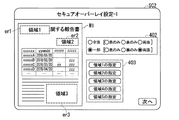
図6は、セキュアオーバーレイの設定画面を示す第1の図である。表示画面SC1(図5)のボタン「次へ」が選択されると、操作パネルおよび表示部304に設定画面SC2が表示される。設定画面SC2は、原稿画像のプレビュー画像M1、チェックボックス402、及び、領域指定メニュー403を有する。
FIG. 6 is a first diagram illustrating a secure overlay setting screen. When the button “Next” on the display screen SC1 (FIG. 5) is selected, a setting screen SC2 is displayed on the operation panel and the
チェックボックス402は、オーバーレイ画像を形成する領域の種別の指定を受け付ける。具体的に、チェックボックス402は、「全面」または「一部」を選択するボタンを有する。「全面」は、原稿画像の領域の全体に、オーバーレイ画像を形成することを示す。「一部」は、原稿画像の領域のうち一部の領域に、オーバーレイ画像を形成することを示す。
The
チェックボックス402は、さらに、オーバーレイ画像を形成するシートの印刷面の指定を受け付ける。具体的に、チェックボックス402は、「表のみ」、「裏のみ」、及び「両面」を選択するボタンを有する。「表のみ」は、シートの、原稿画像が形成された表面にのみオーバーレイ画像を形成することを示す。「裏のみ」は、シートの表面の反対面にのみオーバーレイ画像を形成することを示す。換言すると、「裏のみ」は、シートの、原稿画像が形成されていない面にのみオーバーレイ画像を形成することを示す。「両面」は、表面と裏面の両方にオーバーレイ画像を形成することを示す。
The
図6に示す設定画面SC2の例によると、シートの両面に対して、原稿画像の領域のうち一部の領域にオーバーレイ画像を形成することが指定される。 According to the example of the setting screen SC2 shown in FIG. 6, it is specified that an overlay image is formed in a part of the original image area on both sides of the sheet.
チェックボックス402において「一部」が選択された場合、領域指定メニュー403は、「一部」の各領域を画定する座標の指定を受け付ける。ユーザは、操作パネルおよび表示部304に表示されたプレビュー画像M1上の所定の領域を、タッチ等の操作によって指定する。これにより、原稿画像における「一部」の領域を画定する座標情報が取得される。
When “part” is selected in the
図6に示す設定画面SC2は、「一部」の領域として、3つの領域(「領域1」、「領域2」、「領域3」)er1〜er3が指定される場合を例示する。以下、オーバーレイ領域er1、オーバーレイ領域er2、オーバーレイ領域er3を区別しない場合、オーバーレイ領域erとも称する。 The setting screen SC2 illustrated in FIG. 6 illustrates a case where three areas (“area 1”, “area 2”, and “area 3”) er1 to er3 are designated as “partial” areas. Hereinafter, when the overlay area er1, the overlay area er2, and the overlay area er3 are not distinguished, they are also referred to as overlay areas er.
設定画面SC2の例では、「領域1」は、プレビュー画像M1における左上のオーバーレイ領域er1を示す。オーバーレイ領域er1は、「ABCの製品X、vol.1」が表示された領域である。前述したとおり、「製品X」は機密内容に関する情報に該当する。 In the example of the setting screen SC2, “region 1” indicates the upper left overlay region er1 in the preview image M1. The overlay area er1 is an area where “ABC product X, vol. 1” is displayed. As described above, “product X” corresponds to information related to confidential content.
「領域2」は、プレビュー画像M1における右上のオーバーレイ領域er2を示す。オーバーレイ領域er2は、文字列「XYZ株式会社、YYYY/MM/DD」が表示された領域である。前述したとおり、「XYZ株式会社」、「YYYY/MM/DD」は機密内容に関する情報に該当する。「領域3」は、プレビュー画像M1における右下のオーバーレイ領域er3を示す。オーバーレイ領域er3は、製品Xの傾向を示すグラフが掲載された領域である。前述したとおり、製品Xの傾向を示すグラフは機密内容に関する情報に該当する。 “Region 2” indicates an upper right overlay region er2 in the preview image M1. The overlay area er2 is an area where the character string “XYZ Corporation, YYYY / MM / DD” is displayed. As described above, “XYZ Corporation” and “YYYY / MM / DD” correspond to information regarding confidential contents. “Region 3” indicates a lower right overlay region er3 in the preview image M1. The overlay area er3 is an area in which a graph indicating the tendency of the product X is posted. As described above, the graph indicating the tendency of the product X corresponds to the information regarding the confidential content.
図4のフローチャートに戻る。オーバーレイを形成するオーバーレイ領域erの情報を取得すると(ACT14)、オーバーレイ処理部309は、オーバーレイ画像の元になる情報の指定を受け付ける。
Returning to the flowchart of FIG. When the information of the overlay area er forming the overlay is obtained (ACT 14), the
図7は、セキュアオーバーレイの設定画面を示す第2の図である。設定画面SC2(図6)のボタン「次へ」が選択されると、操作パネルおよび表示部304に設定画面SC3が表示される。設定画面SC3は、原稿画像のプレビュー画像M1、及び、チェックボックス404を有する。
FIG. 7 is a second diagram illustrating a secure overlay setting screen. When the button “Next” on the setting screen SC2 (FIG. 6) is selected, a setting screen SC3 is displayed on the operation panel and the
チェックボックス404は、オーバーレイ画像の元になる情報の種別の指定を受け付ける。以下、オーバーレイ画像の元になる情報を、指定情報と称する。チェックボックス404は、「画像指定」または「文字列指定」を選択するボタンを有する。「画像指定」は、原稿画像の一部の画像に基づいてオーバーレイ画像を生成することを示す。「文字列指定」は、ユーザが指定する任意の文字列に基づいてオーバーレイ画像を生成することを示す。
The
図7は、指定情報の種別として「画像指定」が選択された場合における設定画面SC3を例示する。「画像指定」が選択された場合、設定画面SC3は、原稿画像の一部の画像(以下、部分画像とも称する)の領域の指定を受け付ける。ユーザは、操作パネルおよび表示部304に表示されたプレビュー画像M1上の所定の領域を、タッチ等の操作によって指定する。これにより、部分画像を画定する座標情報が取得される。
FIG. 7 exemplifies the setting screen SC3 when “image specification” is selected as the type of the specification information. When "image designation" is selected, the setting screen SC3 accepts designation of an area of a partial image (hereinafter, also referred to as a partial image) of the document image. The user specifies a predetermined area on the preview image M1 displayed on the operation panel and the
図7に示す設定画面SC3によると、プレビュー画像M1における左上の部分画像M2が指定される。部分画像M2は、ロゴによって表された「ABC」、及び文字列「vol.1」を含む。なお、部分画像M2は、図7の例に限定されるものではない。部分画像M2は、原稿画像における表の一部や、他の文字列等を含んでいてもよい。また、部分画像M2は、イラストや写真等の画像を含んでいてもよい。 According to the setting screen SC3 shown in FIG. 7, the upper left partial image M2 in the preview image M1 is specified. The partial image M2 includes “ABC” represented by a logo and a character string “vol.1”. Note that the partial image M2 is not limited to the example of FIG. The partial image M2 may include a part of a table in the document image, another character string, or the like. Further, the partial image M2 may include an image such as an illustration or a photograph.
図8は、セキュアオーバーレイの設定画面を示す第3の図である。図8は、指定情報の種別として「文字列指定」が選択された場合における設定画面SC4を例示する。「文字列指定」が選択された場合、テキスト入力欄405は、オーバーレイ画像の元となる文字列の指定を受け付ける。ユーザは、操作パネルおよび表示部304を操作することによって、テキスト入力欄405に任意の文字列を入力する。
FIG. 8 is a third diagram showing a secure overlay setting screen. FIG. 8 illustrates a setting screen SC4 when “character string specification” is selected as the type of the specification information. When “character string designation” is selected, the
文字列は、原稿画像の内容を認識しているユーザによって指定される。したがって、例えば、原稿画像がどのような内容であるかを、原稿画像の内容を認識しているユーザに判別可能にする文字列が指定される。図8に示す設定画面SC4によると、文字列「ABC2018vol1」が指定される。文字列「ABC2018vol1」は、例えば、原稿画像が「2018」年における会社「ABC」に関する「vol1」の文書であることを示す。文字列は、原稿画像の分類や目的、組織等を示す情報を含んでいてもよい。また、文字列は、任意の日付や、タイムスタンプ等を含んでいてもよい。 The character string is specified by a user who recognizes the contents of the document image. Therefore, for example, a character string that allows the user who is recognizing the content of the document image to determine the content of the document image is specified. According to the setting screen SC4 shown in FIG. 8, the character string “ABC2018vol1” is specified. The character string “ABC2018vol1” indicates, for example, that the document image is a document of “vol1” regarding the company “ABC” in “2018”. The character string may include information indicating the classification, purpose, organization, and the like of the document image. Further, the character string may include an arbitrary date, a time stamp, and the like.
図4のフローチャートに戻る。指定情報として「画像指定」が選択された場合(ACT15のYES)、オーバーレイ処理部309は部分画像M2のトリミングを行う(ACT16)。オーバーレイ処理部309は、部分画像M2の座標情報に基づいて、原稿画像の画像データから部分画像M2の画像データを抽出し、指定画像データを生成する。
Returning to the flowchart of FIG. When “image specification” is selected as the specification information (ACT 15: YES), the
イメージリピート処理部310は、生成した指定画像データの縮小処理を行う(ACT17)。イメージリピート処理部310は、指定画像データの画像密度が所定の画像密度以上になる所定の縮小率にしたがって、指定画像データの縮小処理を行う。画像密度は、例えば、単位面積当たりのトナーの被覆率や画像濃度である。所定の画像密度は、原稿画像の情報を適切にマスク可能な値を示す。所定の縮小率は、例えば、検証等にしたがって設定される。イメージリピート処理部310は、縮小処理後の指定画像データを、メモリ302に記憶する(ACT18)。
The image
一方、指定情報として「文字列指定」が選択された場合(ACT15のNO)、イメージリピート処理部310は、入力された文字列に基づいて指定画像データを生成する。イメージリピート処理部310は、設定画面SC4で入力された文字列「ABC2018vol1」を表す指定画像データを生成する。
On the other hand, when “character string specification” is selected as the specification information (ACT 15: NO), the image
イメージリピート処理部310は、指定画像データの画像密度が所定の画像密度以下になる所定のフォントサイズの文字列を表す指定画像データを生成する。画像密度については、前述したとおりである。所定のフォントサイズは、例えば、所定の画像密度に基づいて、検証等にしたがって設定される。イメージリピート処理部310は、生成した指定画像データを、メモリ302に記憶する(ACT18)。
The image
イメージリピート処理部310は、指定画像データのイメージリピート処理を行い、オーバーレイ画像データを生成する(ACT19)。具体的に、イメージリピート処理部310は、指定画像データを主走査方向、副走査方向のいずれかまたは両方に繰り返したオーバーレイ画像データを生成する。イメージリピート処理部310は、生成したオーバーレイ画像データをメモリ302に記憶する(ACT20)。
The image
図9は、縮小処理(ACT17)、及びイメージリピート処理(ACT19)の例を模式的に説明する図である。図9は、指定情報として部分画像M2(図7)が選択された場合を例示する。 FIG. 9 is a diagram schematically illustrating an example of the reduction process (ACT17) and the image repeat process (ACT19). FIG. 9 illustrates a case where the partial image M2 (FIG. 7) is selected as the designation information.
イメージリピート処理部310は、部分画像M2の画像データを所定の縮小率にしたがって縮小し、図9に示す指定画像データM21を生成する。イメージリピート処理部310は、指定画像データM21を主走査方向および副走査方向に繰り返して、図9に示すオーバーレイ画像データM22を生成する。指定画像データM21が所定の画像密度を有することにより、原稿画像の情報を適切にマスク可能なオーバーレイ画像を生成できる。
The image
なお、イメージリピート処理部310は、傾斜処理が行われたオーバーレイ画像データM23を生成してもよい。この場合、イメージリピート処理部310は、所定の角度にしたがって指定画像データM21の画像を傾斜させる。また、イメージリピート処理部310は、傾斜処理された指定画像データM21が主走査方向および副走査方向に繰り返されたオーバーレイ画像データM23を生成する。指定情報として、「文字列指定」が選択された場合についても同様である。
傾斜処理が行われたオーバーレイ画像データM23における行及び列の方向は、原稿画像における行及び列の方向と異なる。このため、オーバーレイ画像データM23を用いることにより、原稿画像の情報をより適切にマスクすることができる。
Note that the image
The row and column directions in the skewed overlay image data M23 are different from the row and column directions in the document image. Therefore, by using the overlay image data M23, the information of the document image can be more appropriately masked.
図4のフローチャートに戻る。オーバーレイ画像データを生成すると、画像処理部307は、原稿画像の画像データの画像処理を行う(ACT21)。これにより、原稿画像の印刷データが生成される。画像処理は、例えば、フィルタ処理、階調処理等を含む。なお、画像処理は、他の処理を含んでもよい。
Returning to the flowchart of FIG. After generating the overlay image data, the
オーバーレイ処理部309は、イメージオーバーレイ処理を行う(ACT22)。オーバーレイ処理部309は、原稿画像の画像データに、オーバーレイ画像データを合成する。具体的に、オーバーレイ処理部309は、原稿画像の画像データのオーバーレイ領域erに、オーバーレイ画像データを合成する。
また、オーバーレイ処理部309は、オーバーレイ領域erにオーバーレイ画像が配置されたオーバーレイ用の画像データを生成する。画像処理部307は、オーバーレイ用の画像データの画像処理を行い、オーバーレイ用の印刷データを生成する。
The
Further, the
プレビュー画像生成部308は、イメージオーバーレイ処理の結果に基づいて、オーバーレイ画像が合成されたプレビュー画像データを生成する(ACT23)。CPU301は、操作パネルおよび表示部304に、生成したプレビュー画像を表示させる。
The preview
図示していないが、操作パネルおよび表示部304は、オーバーレイ画像の再生成を選択可能にするボタンをさらに表示してもよい。これにより、例えば、オーバーレイ画像の画像密度が十分でない場合に、縮小率又はフォントサイズを変更してオーバーレイ画像を再生成することができる。また、オーバーレイ領域erや指定情報を変更したい場合に、オーバーレイ画像を再生成することができる。再生成が選択された場合、処理ACT13〜ACT23の処理が再度、実行される。
Although not shown, the operation panel and the
プリント部305は、生成された印刷データに基づいて、印刷ジョブで指定された印刷面に、画像を形成する(ACT24)。プリント部305は、非消色トナープリント制御部311を制御し、処理ACT21で生成された原稿画像の印刷データに基づいて、非消色トナーによる画像形成を行う。
The
プリント部305は、非消色トナーによって原稿画像の画像形成が行われたシートに対して、消色トナーによってオーバーレイ画像の画像形成を行う。プリント部305は、設定画面SC2(図6)で指定された印刷面に対して、オーバーレイ画像の画像形成を行う。具体的に、プリント部305は、プリント制御部311を制御し、オーバーレイ用の印刷データに基づいて画像形成を行う。これにより、指定された印刷面に対して、消色トナーによってオーバーレイ画像が形成される。以下、画像形成が行われたシートを、印刷画像とも称する。
The
図10は、オーバーレイ画像が形成された印刷画像の第1の例を示す図である。図10は、指定情報として部分画像M2(図7)が指定された場合の印刷画像を例示する。また、図10は、シートの「両面」にオーバーレイ画像が形成される場合の印刷画像を示す。図10は、印刷画像の表面ST11及び裏面ST12を表す。 FIG. 10 is a diagram illustrating a first example of a print image on which an overlay image has been formed. FIG. 10 illustrates a print image when the partial image M2 (FIG. 7) is specified as the specification information. FIG. 10 shows a print image when an overlay image is formed on “both sides” of a sheet. FIG. 10 shows the front surface ST11 and the back surface ST12 of the print image.
表面ST11によると、オーバーレイ領域er1〜er3に、原稿画像に重ねて、部分画像M2に基づくオーバーレイ画像が形成されている。つまり、オーバーレイ画像によって、原稿画像におけるオーバーレイ領域er1〜er3の情報がマスクされている。原稿画像の内容を認識しているユーザは、オーバーレイ画像に含まれるロゴ「ABC」及び文字列「vol.1」に基づくことにより、どのような原稿画像であるかを判別することができる。 According to the front surface ST11, an overlay image based on the partial image M2 is formed in the overlay areas er1 to er3 so as to overlap the original image. That is, the information of the overlay areas er1 to er3 in the document image is masked by the overlay image. A user recognizing the contents of the original image can determine what the original image is based on the logo “ABC” and the character string “vol.1” included in the overlay image.
裏面ST12には、オーバーレイ画像のみが形成されている。具体的に、裏面ST12では、表面ST11におけるオーバーレイ領域er1〜er3の裏側の領域に、オーバーレイ画像が形成されている。換言すると、裏面ST12では、表面ST11のオーバーレイ領域er1〜er3の線対称の領域に、オーバーレイ画像が形成されている。これにより、原稿画像のオーバーレイ領域er1〜er3の情報が、裏面ST12からもマスクされている。 On the back surface ST12, only an overlay image is formed. Specifically, on the back surface ST12, an overlay image is formed in a region on the back side of the overlay regions er1 to er3 on the front surface ST11. In other words, on the back surface ST12, an overlay image is formed in a line-symmetric region of the overlay regions er1 to er3 on the front surface ST11. Thus, the information of the overlay areas er1 to er3 of the document image is also masked from the back surface ST12.
このように、ユーザが指定した情報に基づくオーバーレイ画像が、原稿画像に重複するように形成される。図10の例では、画像形成装置100は、原稿画像の一部の画像に基づいてオーバーレイ画像を生成する。このため、原稿画像の内容を認識しているユーザは、オーバーレイ画像に基づいて、どのような原稿画像であるかを判別することができる。換言すると、ユーザは、オーバーレイ画像が形成されている場合であっても、どのような原稿画像であるかを判別できる。
In this way, the overlay image based on the information specified by the user is formed so as to overlap the original image. In the example of FIG. 10, the
一方、第3者は、原稿画像の内容を認識していない。このため、第3者は、オーバーレイ画像が形成されていることにより、消色処理が行われていない状態では、どのような原稿画像であるかを判別できない。このように、排出された印刷画像が第3者に見られた場合であっても、原稿画像の機密性を保つことができる。 On the other hand, the third party does not recognize the contents of the document image. For this reason, the third party cannot determine what kind of document image is in the state where the color erasing process is not performed because the overlay image is formed. In this way, even if the discharged print image is viewed by a third party, the confidentiality of the document image can be maintained.
したがって、本実施の形態によると、画像形成装置100に施錠できる排出先を設けることなく、原稿の内容が漏えいするリスクを低減することができる。また、消色処理が行われていない場合、印刷画像の廃棄の際に、印刷画像の裁断や塗りつぶしを行う必要がない。また、オーバーレイ画像は消色トナーで画像形成されているため、消色処理を行うことによって、ユーザは、原稿画像の内容を閲覧することができる。
Therefore, according to the present embodiment, it is possible to reduce the risk of the contents of the document leaking without providing a lockable discharge destination in
また、画像形成装置100は、例えば、印刷画像を、原稿画像が形成された表面を下に向けて排出する。すなわち、画像形成装置100は、印刷画像を、原稿画像が形成されていない裏面を上に向けて排出する。このとき、表面に形成された原稿画像が裏面から透けて、第3者が原稿画像の内容を認識できてしまう場合がある。
The
これに対し、本実施の形態では、表面の原稿画像の機密情報を、裏面からオーバーレイ画像によってマスクする。これにより、第3者に、裏面から原稿画像の内容が容易に認識されるリスクを低減することができる。また、両面にオーバーレイ画像が形成される場合、第3者が印刷画像を手に取って透かした場合でも、原稿画像の内容が認識されることを困難にすることができる。 On the other hand, in the present embodiment, the confidential information of the document image on the front surface is masked by the overlay image from the back surface. This can reduce the risk that a third party can easily recognize the contents of the document image from the back surface. In addition, when an overlay image is formed on both sides, it is possible to make it difficult for a third party to recognize the contents of the document image even if the third person picks up the print image and watermarks it.
図11は、オーバーレイ画像が形成された印刷画像の第2の例を示す図である。図11は、指定情報として文字列「ABC2018vol1」(図8)が指定された場合の印刷画像を例示する。また、図11は、図10と同様にして、シートの「両面」にオーバーレイ画像が形成される場合の印刷画像を示す。図11は、印刷画像の表面ST21及び裏面ST22を表す。 FIG. 11 is a diagram illustrating a second example of a print image on which an overlay image has been formed. FIG. 11 illustrates a print image when the character string “ABC2018vol1” (FIG. 8) is specified as the specification information. FIG. 11 shows a print image in the case where an overlay image is formed on “both sides” of a sheet, similarly to FIG. FIG. 11 shows the front surface ST21 and the back surface ST22 of the print image.
表面ST21によると、オーバーレイ領域er1〜er3に、原稿画像に重ねて、文字列「ABC2018vol1」に基づくオーバーレイ画像が形成されている。オーバーレイ画像によって、原稿画像のオーバーレイ領域er1〜er3の情報がマスクされている。原稿画像の内容を認識しているユーザは、オーバーレイ画像に含まれる文字列「ABC2018vol1」に基づいて、どのような原稿画像であるかを判別することができる。 According to the front surface ST21, an overlay image based on the character string "ABC2018vol1" is formed in the overlay areas er1 to er3 so as to overlap the original image. The information of the overlay areas er1 to er3 of the original image is masked by the overlay image. A user recognizing the contents of the document image can determine what the document image is based on the character string “ABC2018vol1” included in the overlay image.
裏面ST22には、文字列「ABC2018vol1」に基づくオーバーレイ画像のみが形成されている。具体的に、裏面ST22では、表面ST21におけるオーバーレイ領域er1〜er3の裏側の領域に、オーバーレイ画像が形成されている。換言すると、裏面ST22では、表面ST21のオーバーレイ領域er1〜er3の線対称の領域に、オーバーレイ画像が形成されている。これにより、原稿画像のオーバーレイ領域er1〜er3の情報が、裏面ST22からもマスクされている。 On the back surface ST22, only an overlay image based on the character string "ABC2018vol1" is formed. Specifically, on the back surface ST22, an overlay image is formed in a region on the back side of the overlay regions er1 to er3 on the front surface ST21. In other words, on the back surface ST22, an overlay image is formed in a line-symmetric region of the overlay regions er1 to er3 of the front surface ST21. Thus, the information of the overlay areas er1 to er3 of the original image is also masked from the back surface ST22.
図11の例においても、図10で述べた効果と同様の効果を奏する。また、図11の例によると、画像形成装置100は、ユーザによって指定された任意の文字列に基づいてオーバーレイ画像を生成する。例えば、ユーザは、原稿画像の内容を認識しているユーザであれば、どのような原稿画像であるかを判別可能にする文字列を指定する。このため、ユーザは、オーバーレイ画像が形成されている場合であっても、オーバーレイ画像に基づいてどのような原稿画像であるかを判別することができる。一方、第3者は、オーバーレイ画像が形成されているため、消色処理が行われていない状態ではどのような原稿画像であるかを判別できない。
Also in the example of FIG. 11, the same effect as the effect described in FIG. 10 is obtained. According to the example in FIG. 11, the
なお、図10、図11の例では、原稿画像の「一部」にオーバーレイ画像が形成される場合を例示したが、この例に限定されるものではない。原稿画像の「全面」にオーバーレイ画像が形成されてもよい。本実施の形態では、ユーザが指定した情報に基づいてオーバーレイ画像を生成する。「全面」にオーバーレイ画像が形成される場合、原稿画像がオーバーレイ画像によって覆われる。この場合においても、ユーザは、オーバーレイ画像に基づくことにより、どのような原稿画像であるかを判別することができる。 Note that, in the examples of FIGS. 10 and 11, the case where the overlay image is formed on “a part” of the document image is illustrated, but the present invention is not limited to this example. An overlay image may be formed on the “entire surface” of the document image. In the present embodiment, an overlay image is generated based on information specified by the user. When an overlay image is formed on “entire surface”, the original image is covered by the overlay image. Also in this case, the user can determine what the original image is based on the overlay image.
また、図10、図11の例では、複数のオーバーレイ領域erに対して、同一のオーバーレイ画像を形成する場合を例示したが、この例に限定されるものではない。オーバーレイ領域erごとに異なる指定情報に基づいて、オーバーレイ画像が形成されてもよい。または、オーバーレイ領域erごとに指定情報の種別(指定画像、指定文字列)が異なってもよい。 Further, in the examples of FIGS. 10 and 11, the case where the same overlay image is formed on a plurality of overlay areas er is illustrated, but the present invention is not limited to this example. An overlay image may be formed based on different designation information for each overlay area er. Alternatively, the type of the designated information (designated image, designated character string) may be different for each overlay area er.
さらに、図10、図11の例では、印刷面として「両面」が指定される場合を例示した。ただし、印刷面として「裏面のみ」が指定される場合についても、印刷画像の秘匿性を高めることができる。前述したとおり、印刷画像の排出時に、表面に形成された原稿画像が裏面から透けて判別できる場合がある。このような場合、裏面にオーバーレイ画像が形成されていることにより、排出された原稿画像の内容が第3者に判別されることを困難にすることができる。 Further, in the examples of FIGS. 10 and 11, the case where “double-sided” is designated as the printing surface has been illustrated. However, even when “only the back side” is designated as the print side, the confidentiality of the print image can be enhanced. As described above, when the print image is discharged, the original image formed on the front surface may be distinguishable from the back surface in some cases. In such a case, since the overlay image is formed on the back surface, it is possible to make it difficult for a third party to determine the content of the discharged document image.
以上のように、実施形態の画像形成装置100は、制御部(オーバーレイ処理部309)と、画像形成部(プリント部305)とを有する。制御部は、ユーザによって指定された指定画像または指定文字列に基づいてオーバーレイ画像(第1の画像)の画像データを生成する。画像形成部は、所定の領域に、画像データに基づいて消色トナーによってオーバーレイ画像を形成する。画像形成部は、表面と、表面の反対面との少なくともいずれかの面に第1の画像を形成する。表面は、非消色トナーによって原稿画像(第2の画像)が形成されたシートの原稿画像が形成された面である。
As described above, the
本実施の形態における画像形成装置100は、ユーザによって指定された任意の情報に基づいてオーバーレイ画像を形成する。これにより、原稿画像の内容を認識しているユーザは、消色処理が行われていない状態であっても、オーバーレイ画像に基づいて、どのような原稿画像であるかを判別できる。一方、原稿画像の内容を認識していない第3者は、オーバーレイ画像が形成されていることにより、どのような原稿画像であるかを判別できない。
これにより、画像形成装置100は、印刷画像の内容が第3者に認識されることを困難にすることができる。したがって、施錠できる排出先を画像形成装置100に設けることなく、原稿画像の内容が漏えいするリスクを低減することができる。また、消色処理が行われていない場合、印刷画像を廃棄する際に、印刷画像の裁断や塗りつぶしを行う必要がない。
Thus, the
また、本実施の形態の画像形成装置100において、指定画像は、第2の画像(原稿画像)の一部の画像である。オーバーレイ画像が原稿画像の一部の画像に基づいていることによりユーザは、どのような原稿画像であるかをより簡明に判別することができる。また、原稿画像の一部の画像を使用することで、新たにオーバーレイ画像を用意する必要がない。このため、オーバーレイ画像を簡易に生成することができる。
In the
また、本実施の形態のおける所定の領域は、第2の画像(原稿画像)が形成された領域のうち、ユーザによって指定された1つ以上の部分領域である。ユーザは、原稿画像に含まれる機密内容の配置や量に応じて、任意の領域にオーバーレイ画像を形成することができる。また、ユーザは、情報をマスクしたい領域にのみオーバーレイ画像を形成することができる。 Further, the predetermined area in the present embodiment is one or more partial areas specified by the user among the areas where the second image (original image) is formed. The user can form an overlay image in an arbitrary area according to the arrangement and amount of the confidential contents included in the document image. Further, the user can form an overlay image only in an area where information is desired to be masked.
また、本実施の形態の制御部は、指定画像または指定文字列に基づいて、所定の画像密度を有する第1の画像(オーバーレイ画像)の画像データを生成する。これにより、画像形成装置100は、どのような指定情報が指定された場合であっても、原稿画像を適切にマスクするオーバーレイ画像を形成することができる。
Further, the control unit according to the present embodiment generates image data of a first image (overlay image) having a predetermined image density based on a specified image or a specified character string. Thus, the
また、上述した実施形態では、原稿画像の画像形成、及び、オーバーレイ画像の画像形成が一連の処理として行われる場合を例示した。ただし、この例に限定されるものではない。画像形成装置100は、原稿画像が既に形成されたシートに対して、オーバーレイ画像の画像形成のみを行ってもよい。
この場合、画像形成装置100のスキャナ部306は、原稿画像を読み取り、画像データを生成する。オーバーレイ処理部309は、生成された原稿画像の画像データに基づいて、オーバーレイ領域の指定や、部分画像の指定を受け付ける。プリント部305は、原稿画像が既に形成されたシートに対して、消色トナーによって、オーバーレイ画像のみの画像形成を行う。
Further, in the above-described embodiment, the case where the image formation of the document image and the image formation of the overlay image are performed as a series of processes has been exemplified. However, it is not limited to this example. The
In this case, the
なお、上述した実施形態では、ユーザが操作パネルおよび表示部304を介して指定情報を入力する場合を例示した。ただし、指定情報は、画像形成装置100とネットワークを介して接続する端末装置上において、指定されてもよい。例えば、端末装置で動作するプリンタドライバは、印刷ジョブの送信時に、指定情報の入力を受け付ける。プリンタドライバは、指定情報が含まれた印刷ジョブを、画像形成装置100に送信する。これにより、ユーザが、操作パネルおよび表示部304を介して情報を入力する手間を省くことがでる。
Note that, in the above-described embodiment, a case where the user inputs designation information via the operation panel and the
以上、本発明のいくつかの実施形態を説明したが、これらの実施形態は、例として提示したものであり、発明の範囲を限定することは意図していない。これら実施形態は、その他の様々な形態で実施されることが可能であり、発明の要旨を逸脱しない範囲で、種々の省略、置き換え、変更を行うことができる。これら実施形態やその変形は、発明の範囲や要旨に含まれると同様に、特許請求の範囲に記載された発明とその均等の範囲に含まれるものである。 While some embodiments of the present invention have been described above, these embodiments have been presented by way of example only, and are not intended to limit the scope of the inventions. These embodiments can be implemented in other various forms, and various omissions, replacements, and changes can be made without departing from the spirit of the invention. These embodiments and modifications thereof are included in the scope and gist of the invention, and are also included in the invention described in the claims and the equivalents thereof.
100…画像形成装置、110…ディスプレイ、120…コントロールパネル、130…プリンタ、140…シート収容部、200…画像読取部、301…CPU、302…メモリ、303…記憶装置、304…操作パネルおよび表示部、305…プリント部、306…スキャナ部、307…画像処理部、308…プレビュー画像生成部、309…オーバーレイ処理部、310…イメージリピート処理部、311…プリント制御部
100 image forming apparatus, 110 display, 120 control panel, 130 printer, 140 sheet receiving section, 200 image reading section, 301 CPU, 302 memory, 303 storage device, 304 operation panel and
Claims (5)
非消色記録剤によって第2の画像が形成された媒体の前記第2の画像が形成された表面と、前記表面の反対面との少なくともいずれかの面における所定の領域に、前記画像データに基づいて消色記録剤によって前記第1の画像を形成する画像形成部と、
を備える画像形成装置。 A control unit configured to generate image data of a first image based on a specified image or a specified character string specified by a user;
The surface of the medium on which the second image is formed by the non-decolorizable recording agent, and the image data on a predetermined area on at least one of the surface opposite to the surface and the surface opposite to the surface. An image forming unit that forms the first image with a decolorizing recording agent based on the
An image forming apparatus comprising:
非消色記録剤によって第2の画像が形成された媒体の前記第2の画像が形成された表面と、前記表面の反対面との少なくともいずれかの面における所定の領域に、前記画像データに基づいて消色記録剤によって前記第1の画像を形成する、
画像形成方法。 Generating image data of a first image based on a specified image or a specified character string specified by a user;
The surface of the medium on which the second image is formed by the non-decolorizable recording agent, and the image data on a predetermined area on at least one of the surface opposite to the surface and the surface opposite to the surface. Forming the first image with a decolorizing recording agent based on the
Image forming method.
Priority Applications (4)
| Application Number | Priority Date | Filing Date | Title |
|---|---|---|---|
| JP2018126021A JP2020003756A (en) | 2018-07-02 | 2018-07-02 | Image forming apparatus and image forming method |
| US16/205,833 US20200007715A1 (en) | 2018-07-02 | 2018-11-30 | Image forming apparatus and image forming method |
| CN201910531269.5A CN110677547A (en) | 2018-07-02 | 2019-06-19 | Image forming apparatus and image forming method |
| US16/877,229 US20200280655A1 (en) | 2018-07-02 | 2020-05-18 | Image forming apparatus and image forming method |
Applications Claiming Priority (1)
| Application Number | Priority Date | Filing Date | Title |
|---|---|---|---|
| JP2018126021A JP2020003756A (en) | 2018-07-02 | 2018-07-02 | Image forming apparatus and image forming method |
Publications (1)
| Publication Number | Publication Date |
|---|---|
| JP2020003756A true JP2020003756A (en) | 2020-01-09 |
Family
ID=69055512
Family Applications (1)
| Application Number | Title | Priority Date | Filing Date |
|---|---|---|---|
| JP2018126021A Pending JP2020003756A (en) | 2018-07-02 | 2018-07-02 | Image forming apparatus and image forming method |
Country Status (3)
| Country | Link |
|---|---|
| US (2) | US20200007715A1 (en) |
| JP (1) | JP2020003756A (en) |
| CN (1) | CN110677547A (en) |
Family Cites Families (4)
| Publication number | Priority date | Publication date | Assignee | Title |
|---|---|---|---|---|
| JP3930502B2 (en) * | 2004-03-29 | 2007-06-13 | 沖電気工業株式会社 | Quality adjustment system and watermark quality inspection device |
| US8711401B2 (en) * | 2010-05-27 | 2014-04-29 | Xerox Corporation | Facility to reuse paper |
| JP5731549B2 (en) * | 2013-01-07 | 2015-06-10 | 株式会社東芝 | Decoloring processing method and decoloring apparatus |
| JP6050842B2 (en) * | 2015-01-30 | 2016-12-21 | 京セラドキュメントソリューションズ株式会社 | Image forming apparatus |
-
2018
- 2018-07-02 JP JP2018126021A patent/JP2020003756A/en active Pending
- 2018-11-30 US US16/205,833 patent/US20200007715A1/en not_active Abandoned
-
2019
- 2019-06-19 CN CN201910531269.5A patent/CN110677547A/en active Pending
-
2020
- 2020-05-18 US US16/877,229 patent/US20200280655A1/en not_active Abandoned
Also Published As
| Publication number | Publication date |
|---|---|
| US20200007715A1 (en) | 2020-01-02 |
| CN110677547A (en) | 2020-01-10 |
| US20200280655A1 (en) | 2020-09-03 |
Similar Documents
| Publication | Publication Date | Title |
|---|---|---|
| US8649066B2 (en) | Image display device and image forming apparatus with security control features | |
| JP5533891B2 (en) | Operation display device, control method thereof, and control program thereof | |
| US9170727B2 (en) | Image processing apparatus, display method, and computer-readable storage medium storing display program | |
| JP5931841B2 (en) | Document reading apparatus and image forming apparatus | |
| US9628639B2 (en) | Printer driver that causes a computer to generate a print command to print with decolorable material | |
| US10990028B2 (en) | Information processing apparatus, image forming system, information processing method, and recording medium | |
| JP5068333B2 (en) | Image forming apparatus | |
| JP6050842B2 (en) | Image forming apparatus | |
| JP2016078356A (en) | Image formation device and image formation method | |
| JP5526089B2 (en) | Input device and image forming apparatus | |
| JP5868893B2 (en) | Image processing device | |
| US9662923B2 (en) | Image forming apparatus and method for processing reused sheet | |
| JP2008011303A (en) | Image processing apparatus | |
| JP2020003756A (en) | Image forming apparatus and image forming method | |
| JP5932752B2 (en) | Image forming apparatus | |
| JP6287783B2 (en) | Image forming apparatus | |
| US9584685B2 (en) | Image forming apparatus | |
| JP2015197672A (en) | image forming apparatus and program | |
| US20210352182A1 (en) | Image processing device, image forming device and recording medium | |
| US10235613B2 (en) | Image forming device and control method therefor for managing characteristics using a paper profile function | |
| JP2008283397A (en) | Image processing device, image forming apparatus | |
| JP2017083946A (en) | Image forming apparatus, image forming system, and printer driver | |
| JP2005235109A (en) | Image forming system | |
| JP2018113598A (en) | Image formation apparatus and image formation program | |
| JP2013029887A (en) | Image forming apparatus and image forming system |