JP2020003734A - Electronic apparatus - Google Patents
Electronic apparatus Download PDFInfo
- Publication number
- JP2020003734A JP2020003734A JP2018125513A JP2018125513A JP2020003734A JP 2020003734 A JP2020003734 A JP 2020003734A JP 2018125513 A JP2018125513 A JP 2018125513A JP 2018125513 A JP2018125513 A JP 2018125513A JP 2020003734 A JP2020003734 A JP 2020003734A
- Authority
- JP
- Japan
- Prior art keywords
- touch
- electronic device
- touch detection
- detection
- slide operation
- Prior art date
- Legal status (The legal status is an assumption and is not a legal conclusion. Google has not performed a legal analysis and makes no representation as to the accuracy of the status listed.)
- Granted
Links
Images


Classifications
-
- G—PHYSICS
- G06—COMPUTING; CALCULATING OR COUNTING
- G06F—ELECTRIC DIGITAL DATA PROCESSING
- G06F3/00—Input arrangements for transferring data to be processed into a form capable of being handled by the computer; Output arrangements for transferring data from processing unit to output unit, e.g. interface arrangements
- G06F3/01—Input arrangements or combined input and output arrangements for interaction between user and computer
- G06F3/03—Arrangements for converting the position or the displacement of a member into a coded form
- G06F3/041—Digitisers, e.g. for touch screens or touch pads, characterised by the transducing means
- G06F3/044—Digitisers, e.g. for touch screens or touch pads, characterised by the transducing means by capacitive means
-
- G—PHYSICS
- G06—COMPUTING; CALCULATING OR COUNTING
- G06F—ELECTRIC DIGITAL DATA PROCESSING
- G06F3/00—Input arrangements for transferring data to be processed into a form capable of being handled by the computer; Output arrangements for transferring data from processing unit to output unit, e.g. interface arrangements
- G06F3/01—Input arrangements or combined input and output arrangements for interaction between user and computer
- G06F3/048—Interaction techniques based on graphical user interfaces [GUI]
- G06F3/0484—Interaction techniques based on graphical user interfaces [GUI] for the control of specific functions or operations, e.g. selecting or manipulating an object, an image or a displayed text element, setting a parameter value or selecting a range
- G06F3/04847—Interaction techniques to control parameter settings, e.g. interaction with sliders or dials
-
- G—PHYSICS
- G06—COMPUTING; CALCULATING OR COUNTING
- G06F—ELECTRIC DIGITAL DATA PROCESSING
- G06F3/00—Input arrangements for transferring data to be processed into a form capable of being handled by the computer; Output arrangements for transferring data from processing unit to output unit, e.g. interface arrangements
- G06F3/01—Input arrangements or combined input and output arrangements for interaction between user and computer
- G06F3/03—Arrangements for converting the position or the displacement of a member into a coded form
- G06F3/033—Pointing devices displaced or positioned by the user, e.g. mice, trackballs, pens or joysticks; Accessories therefor
- G06F3/0354—Pointing devices displaced or positioned by the user, e.g. mice, trackballs, pens or joysticks; Accessories therefor with detection of 2D relative movements between the device, or an operating part thereof, and a plane or surface, e.g. 2D mice, trackballs, pens or pucks
- G06F3/03547—Touch pads, in which fingers can move on a surface
-
- G—PHYSICS
- G06—COMPUTING; CALCULATING OR COUNTING
- G06F—ELECTRIC DIGITAL DATA PROCESSING
- G06F3/00—Input arrangements for transferring data to be processed into a form capable of being handled by the computer; Output arrangements for transferring data from processing unit to output unit, e.g. interface arrangements
- G06F3/01—Input arrangements or combined input and output arrangements for interaction between user and computer
- G06F3/03—Arrangements for converting the position or the displacement of a member into a coded form
- G06F3/033—Pointing devices displaced or positioned by the user, e.g. mice, trackballs, pens or joysticks; Accessories therefor
- G06F3/0362—Pointing devices displaced or positioned by the user, e.g. mice, trackballs, pens or joysticks; Accessories therefor with detection of 1D translations or rotations of an operating part of the device, e.g. scroll wheels, sliders, knobs, rollers or belts
-
- G—PHYSICS
- G06—COMPUTING; CALCULATING OR COUNTING
- G06F—ELECTRIC DIGITAL DATA PROCESSING
- G06F3/00—Input arrangements for transferring data to be processed into a form capable of being handled by the computer; Output arrangements for transferring data from processing unit to output unit, e.g. interface arrangements
- G06F3/01—Input arrangements or combined input and output arrangements for interaction between user and computer
- G06F3/03—Arrangements for converting the position or the displacement of a member into a coded form
- G06F3/033—Pointing devices displaced or positioned by the user, e.g. mice, trackballs, pens or joysticks; Accessories therefor
- G06F3/038—Control and interface arrangements therefor, e.g. drivers or device-embedded control circuitry
-
- G—PHYSICS
- G06—COMPUTING; CALCULATING OR COUNTING
- G06F—ELECTRIC DIGITAL DATA PROCESSING
- G06F3/00—Input arrangements for transferring data to be processed into a form capable of being handled by the computer; Output arrangements for transferring data from processing unit to output unit, e.g. interface arrangements
- G06F3/01—Input arrangements or combined input and output arrangements for interaction between user and computer
- G06F3/048—Interaction techniques based on graphical user interfaces [GUI]
- G06F3/0481—Interaction techniques based on graphical user interfaces [GUI] based on specific properties of the displayed interaction object or a metaphor-based environment, e.g. interaction with desktop elements like windows or icons, or assisted by a cursor's changing behaviour or appearance
- G06F3/0482—Interaction with lists of selectable items, e.g. menus
-
- H—ELECTRICITY
- H04—ELECTRIC COMMUNICATION TECHNIQUE
- H04N—PICTORIAL COMMUNICATION, e.g. TELEVISION
- H04N23/00—Cameras or camera modules comprising electronic image sensors; Control thereof
- H04N23/50—Constructional details
- H04N23/51—Housings
-
- H—ELECTRICITY
- H04—ELECTRIC COMMUNICATION TECHNIQUE
- H04N—PICTORIAL COMMUNICATION, e.g. TELEVISION
- H04N23/00—Cameras or camera modules comprising electronic image sensors; Control thereof
- H04N23/50—Constructional details
- H04N23/53—Constructional details of electronic viewfinders, e.g. rotatable or detachable
-
- H—ELECTRICITY
- H04—ELECTRIC COMMUNICATION TECHNIQUE
- H04N—PICTORIAL COMMUNICATION, e.g. TELEVISION
- H04N23/00—Cameras or camera modules comprising electronic image sensors; Control thereof
- H04N23/60—Control of cameras or camera modules
- H04N23/62—Control of parameters via user interfaces
-
- H—ELECTRICITY
- H04—ELECTRIC COMMUNICATION TECHNIQUE
- H04N—PICTORIAL COMMUNICATION, e.g. TELEVISION
- H04N23/00—Cameras or camera modules comprising electronic image sensors; Control thereof
- H04N23/60—Control of cameras or camera modules
- H04N23/63—Control of cameras or camera modules by using electronic viewfinders
- H04N23/631—Graphical user interfaces [GUI] specially adapted for controlling image capture or setting capture parameters
-
- G—PHYSICS
- G06—COMPUTING; CALCULATING OR COUNTING
- G06F—ELECTRIC DIGITAL DATA PROCESSING
- G06F2203/00—Indexing scheme relating to G06F3/00 - G06F3/048
- G06F2203/033—Indexing scheme relating to G06F3/033
- G06F2203/0339—Touch strips, e.g. orthogonal touch strips to control cursor movement or scrolling; single touch strip to adjust parameter or to implement a row of soft keys
Landscapes
- Engineering & Computer Science (AREA)
- General Engineering & Computer Science (AREA)
- Theoretical Computer Science (AREA)
- Human Computer Interaction (AREA)
- Physics & Mathematics (AREA)
- General Physics & Mathematics (AREA)
- Multimedia (AREA)
- Signal Processing (AREA)
- Studio Devices (AREA)
- Camera Bodies And Camera Details Or Accessories (AREA)
- Viewfinders (AREA)
- Position Input By Displaying (AREA)
Abstract
Description
本発明は、電子機器に関し、とくにタッチ操作されるタッチ操作面を有する操作手段の配置構成に関するものである。 The present invention relates to an electronic device, and more particularly to an arrangement of an operation unit having a touch operation surface on which a touch operation is performed.
従来、撮像装置には、十字キーやダイヤルなどの設定項目を選択するための操作部材が搭載されている。 Conventionally, an imaging device is equipped with an operation member for selecting a setting item such as a cross key or a dial.
近年は、表示デバイスとしてタッチパネルを搭載する製品が普及しており、ユーザーは表示された設定項目をタッチするだけで、その項目を選択/設定することが可能となる。 In recent years, products equipped with a touch panel as a display device have become widespread, and a user can select / set an item simply by touching the displayed setting item.
また、操作部材としてタッチセンサを搭載する製品もあり、撮像装置において動画撮影を行う場合のユーザーインターフェースとしても期待が高まっている。 In addition, there are products equipped with a touch sensor as an operation member, and expectations are increasing as a user interface for capturing a moving image in an imaging device.
従来のメカ方式の操作部材で動画撮影中の設定を行うと操作音が雑音として記録されてしまうが、タッチセンサを用いた操作部材では記録される操作音を低減することができる。 If the setting during moving image shooting is performed using a conventional mechanical operation member, the operation sound is recorded as noise. However, the operation member using a touch sensor can reduce the recorded operation sound.
タッチパネル、タッチセンサの方式には静電容量方式、抵抗膜方式、光学方式等の方式があり、いずれの方式にも短所、長所があり、用途に応じて広く用いられている。 Touch panel and touch sensor systems include a capacitance system, a resistive film system, and an optical system. Each system has disadvantages and advantages, and is widely used depending on the application.
その中でも、静電容量方式は、精度よく検出することができ、多くの機器に採用されている。 Among them, the capacitance type can be detected with high accuracy, and is adopted in many devices.
特許文献1では、撮像装置背面の表示画面周辺にタッチ操作部材をL字状に配置する開示があり、タッチパネル使用時に表示画面に直接指が触れて画面が汚れてしまう課題を解消している。 Patent Literature 1 discloses that an L-shaped touch operation member is arranged around a display screen on the back surface of an imaging device, and solves a problem that a finger is directly touched on a display screen when a touch panel is used and the screen is soiled.
それとともに、メカ操作部材削減による機器自体の小型化、薄型化を実現し、かつ操作性を向上させる技術が開示されている。 At the same time, there has been disclosed a technology for realizing a smaller and thinner device itself by reducing the number of mechanical operation members and improving operability.
また、特許文献2では、撮像装置の上面部にタッチ操作部材を配置し、操作部材をユーザーが把持しながら複数の撮影機能を操作できる技術が開示されている。 Further, Patent Literature 2 discloses a technique in which a touch operation member is arranged on an upper surface of an imaging device, and a user can operate a plurality of photographing functions while holding the operation member.
しかしながら、上述の特許文献に開示された従来技術では、タッチ操作部材に設定されたさまざまな機能を把握して操作する。 However, in the related art disclosed in the above-mentioned patent document, various functions set on the touch operation member are grasped and operated.
そのためには、撮像装置の背面に配置された表示画面を見ながら操作することが想定され、タッチ操作部材が配置されている。 For that purpose, it is assumed that operation is performed while looking at a display screen arranged on the back surface of the imaging device, and a touch operation member is arranged.
よって、ファインダーや上面カバーなどにも表示装置が配置されている高機能な撮像装置において、従来技術にあるタッチ操作部材の配置では、ファインダーや上面カバーの表示を見ながらのタッチ操作部材を操作し難いという問題がある。 Therefore, in a high-performance imaging device in which a display device is also arranged in a viewfinder or a top cover, in the arrangement of the touch operation members in the related art, the user operates the touch operation member while watching the display of the viewfinder or the top cover. There is a problem that it is difficult.
とくにファインダーを覗きながらの操作はブラインドでタッチ操作部材を触るため、誤操作をしてしまう可能性がある。 In particular, the operation while looking through the viewfinder touches the touch operation member with a blind, so that an erroneous operation may be performed.
よって、本発明の目的は少なくとも2つ以上の表示モニタを見ながら操作可能なタッチ操作部材を搭載した電子機器を提供することである。 Therefore, an object of the present invention is to provide an electronic device equipped with a touch operation member that can be operated while viewing at least two or more display monitors.
また、ファインダーを覗きながらでもタッチ検出部を把握して操作可能なタッチ操作部材を搭載した電子機器を提供することである。 Another object of the present invention is to provide an electronic device equipped with a touch operation member capable of grasping and operating a touch detection unit while looking through a finder.
上記目的を達成するために、本発明の第1の電子機器は、タッチ操作及びスライド操作される非導電性のタッチ操作面を有する第1の操作手段と、前記タッチ操作面の内側に配置され且つ前記タッチ操作を検知するタッチ検知面と、前記タッチ操作面の周囲を覆うように配置された導電性の外装カバーと、を有する電子機器であって、
前記タッチ検知面は、前記スライド操作の方向において、第1の電極面から第Nの電極面の少なくとも2つの電極面に分割され、
前記タッチ検知面が前記外装カバーと電気的に絶縁されるように、前記タッチ検知面は、前記外装カバーと離間しており、
前記電子機器の背面側から見た場合、前記タッチ操作面は、前記タッチ検知面と重畳するタッチ検出領域と、前記タッチ検出領域の外周に配置され且つ前記タッチ検知面と重畳しないタッチ非検出領域と、を備え、
前記タッチ検出領域と前記タッチ非検出領域との背面側への突出量及び質感及び色の何れか一つが異なることを特徴とする。
In order to achieve the above object, a first electronic device according to the present invention includes a first operation unit having a non-conductive touch operation surface on which a touch operation and a slide operation are performed, and is disposed inside the touch operation surface. An electronic device having a touch detection surface for detecting the touch operation, and a conductive exterior cover arranged to cover the periphery of the touch operation surface,
The touch detection surface is divided into at least two electrode surfaces from a first electrode surface to an Nth electrode surface in the direction of the slide operation,
The touch detection surface is separated from the exterior cover so that the touch detection surface is electrically insulated from the exterior cover,
When viewed from the back side of the electronic device, the touch operation surface is a touch detection region that overlaps the touch detection surface, and a touch non-detection region that is arranged around the touch detection region and does not overlap the touch detection surface. And
The touch detection area and the touch non-detection area are different from each other in the amount of protrusion to the rear side and any one of texture and color.
本発明によれば、タッチ操作面において、スムーズなスライド操作を実現できる。 According to the present invention, a smooth slide operation can be realized on the touch operation surface.
(デジタルカメラ100の外観図)
以下、図面を参照して本発明の好適な実施形態を説明する。
(External view of digital camera 100)
Hereinafter, preferred embodiments of the present invention will be described with reference to the drawings.
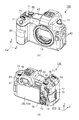
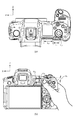
図1(a)、(b)に本発明を適用可能な撮像装置の一例としてのデジタルカメラ100の外観図を示す。
1A and 1B are external views of a
図1(a)はデジタルカメラ100の前面斜視図であり、図1(b)はデジタルカメラ100の背面斜視図である。
FIG. 1A is a front perspective view of the
図1において、表示部28は画像や各種情報を表示する、カメラ背面に設けられた表示部である。タッチパネル70aは、表示部28の表示面(操作面)に対するタッチ操作を検出することができる。
In FIG. 1, a
ファインダー外表示部43は、カメラ上面に設けられた表示部であり、シャッター速度や絞りをはじめとするカメラの様々な設定値が表示される。
The
シャッターボタン61は撮影指示を行うための操作部である。モード切替スイッチ60は各種モードを切り替えるための操作部である。
The
端子カバー40は外部機器との接続ケーブルとデジタルカメラ100とを接続する接続ケーブル等のコネクタ(不図示)を保護するカバーである。
The
メイン電子ダイヤル71は操作部70に含まれる回転操作部材であり、このメイン電子ダイヤル71を回すことで、シャッター速度や絞りなどの設定値の変更等が行える。
The main
電源スイッチ72はデジタルカメラ100の電源のON及びOFFを切り替える操作部材である。
The
サブ電子ダイヤル73は操作部70に含まれ、操作部70に含まれる回転操作部材であり、選択枠の移動や画像送りなどを行える。
The sub
十字キー74は操作部70に含まれ、上、下、左、右部分をそれぞれ押し込み可能な十字キー(4方向キー)である。
The cross key 74 is included in the
十字キー74の押した部分に応じた操作が可能である。SETボタン75は操作部70に含まれ、押しボタンであり、主に選択項目の決定などに用いられる。
An operation corresponding to the pressed part of the cross key 74 is possible. The SET button 75 is included in the
動画ボタン76は、動画撮影(記録)の開始、停止の指示に用いられる。AEロックボタン77は操作部70に含まれ、撮影待機状態で押下することにより、露出状態を固定することができる。
The moving
拡大ボタン78は操作部70に含まれ、撮影モードのライブビュー表示において拡大モードのON、OFFを行うための操作ボタンである。
The
拡大モードをONとしてからメイン電子ダイヤル71を操作することにより、LV画像の拡大、縮小を行える。
By operating the main
再生モードにおいては再生画像を拡大し、拡大率を増加させるための拡大ボタンとして機能する。 In the playback mode, it functions as an enlargement button for enlarging the playback image and increasing the enlargement ratio.
再生ボタン79は操作部70に含まれ、撮影モードと再生モードとを切り替える操作ボタンである。
The
撮影モード中に再生ボタン79を押下することで再生モードに移行し、記録媒体200に記録された画像のうち最新の画像を表示部28に表示させることができる。
By pressing the
メニューボタン81は、操作部70に含まれ、メニューボタン81が押されると各種の設定可能なメニュー画面が表示部28に表示される。
The
ユーザーは、表示部28に表示されたメニュー画面と、十字キー74やSETボタン75を用いて直感的に各種設定を行うことができる。
The user can intuitively perform various settings using the menu screen displayed on the
タッチバー82はタッチ操作を受け付けることが可能なライン状のタッチ操作部材(ラインタッチセンサー)である。
The
把持部としてのグリップ部90を握った右手の親指で操作可能な位置に配置されている。
It is arranged at a position where it can be operated with the thumb of the right hand holding the
タッチバー82に対するタップ操作(タッチして所定期間以内に移動せずに離す操作)、左右へのスライド操作(タッチした後、タッチしたままタッチ位置を移動する操作)などを受け付け可能である。 A tap operation on the touch bar 82 (operation of releasing the touch bar without moving within a predetermined period), a slide operation of right and left (operation of moving the touch position while touching after touching) and the like can be received.
タッチバー82はタッチパネル70aとは異なる操作部材であり、表示機能は備えていない。
The
通信端子10はデジタルカメラ100がレンズ側(着脱可能)と通信を行う為の通信端子である。
The
接眼部16は、接眼ファインダー(覗き込み型のファインダー)の接眼部であり、ユーザーは、接眼部16を介して内部のEVF29に表示された映像を視認することができる。
The
接眼検知部57は接眼部16に撮影者が接眼しているか否かを検知する接眼検知センサーである。
The
蓋202は記録媒体200を格納したスロットの蓋である。
The
グリップ部90は、ユーザーがデジタルカメラ100を構えた際に右手で握りやすい形状とした保持部である。
The
グリップ部90を右手の小指、薬指、中指で握ってデジタルカメラを保持した状態で、右手の人差指で操作可能な位置にシャッターボタン61、メイン電子ダイヤル71が配置されている。
The
また、同じ状態で、右手の親指で操作可能な位置に、サブ電子ダイヤル73、タッチバー82が配置されている。
In the same state, the sub
(デジタルカメラ100の構成例を示すブロック図)
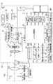
図2は、本実施形態によるデジタルカメラ100の構成例を示すブロック図である。
(Block diagram showing a configuration example of the digital camera 100)
FIG. 2 is a block diagram illustrating a configuration example of the
図2において、レンズユニット150は、交換可能な撮影レンズを搭載するレンズユニットである。
In FIG. 2, a
レンズ103は通常、複数枚のレンズから構成されるが、ここでは簡略して一枚のレンズのみで示している。
The
通信端子6はレンズユニット150がデジタルカメラ100側と通信を行う為の通信端子であり、通信端子10はデジタルカメラ100がレンズユニット150側と通信を行う為の通信端子である。
The communication terminal 6 is a communication terminal for the
レンズユニット150は、この通信端子6,10を介してシステム制御部50と通信している。
The
そして、内部のレンズシステム制御回路4によって絞り駆動回路2を介して絞り1の制御を行い、AF駆動回路3を介して、レンズ103の位置を変位させることで焦点を合わせる。
Then, the aperture 1 is controlled by the internal lens system control circuit 4 via the aperture drive circuit 2, and the position of the
AEセンサー17は、レンズユニット150を通した被写体の輝度を測光する。
The
焦点検出部11は、システム制御部50にデフォーカス量情報を出力する。
The focus detection unit 11 outputs the defocus amount information to the
システム制御部50はそれに基づいてレンズユニット150を制御し、位相差AFを行う。
The
焦点検出部11は、専用の位相差センサーでもよいし、撮像部22の撮像面位相差センサーとして構成しても良い。
The focus detection unit 11 may be a dedicated phase difference sensor or may be configured as an imaging surface phase difference sensor of the
シャッター101は、システム制御部50の制御で撮像部22の露光時間を自由に制御できるフォーカルプレーンシャッターである。
The
撮像部22は、光学像を電気信号に変換するCCDやCMOS素子等で構成される撮像素子である。
The
A/D変換器23は、アナログ信号をデジタル信号に変換する。A/D変換器23は、撮像部22から出力されるアナログ信号をデジタル信号に変換するために用いられる。
The A /
画像処理部24は、A/D変換器23からのデータ、又は、メモリ制御部15からのデータに対し所定の画素補間、縮小といったリサイズ処理や色変換処理を行う。
The
また、画像処理部24では、撮像した画像データを用いて所定の演算処理を行う。画像処理部24により得られた演算結果に基づいてシステム制御部50が露光制御、測距制御を行う。
Further, the
これにより、TTL(スルー・ザ・レンズ)方式のAF(オートフォーカス)処理、AE(自動露出)処理、EF(フラッシュプリ発光)処理が行われる。 As a result, TTL (through-the-lens) AF (auto focus) processing, AE (auto exposure) processing, and EF (flash pre-emission) processing are performed.
画像処理部24では更に、撮像した画像データを用いて所定の演算処理を行い、得られた演算結果に基づいてTTL方式のAWB(オートホワイトバランス)処理を行う。
The
A/D変換器23からの出力データは、画像処理部24及びメモリ制御部15を介して、或いは、メモリ制御部15を介してメモリ32に直接書き込まれる。
Output data from the A /
メモリ32は、撮像部22によって得られA/D変換器23によりデジタルデータに変換された画像データや、表示部28、EVF29に表示するための画像データを格納する。
The
メモリ32は、所定枚数の静止画像や所定時間の動画像および音声を格納するのに十分な記憶容量を備えている。
The
また、メモリ32は画像表示用のメモリ(ビデオメモリ)を兼ねている。
The
D/A変換器19は、メモリ32に格納されている画像表示用のデータをアナログ信号に変換して表示部28、EVF29に供給する。
The D /
こうして、メモリ32に書き込まれた表示用の画像データはD/A変換器19を介して表示部28、EVF29により表示される。
Thus, the display image data written in the
表示部28、EVF29は、LCDや有機EL等の表示器上に、D/A変換器19からのアナログ信号に応じた表示を行う。
The
A/D変換器23によって一度A/D変換されメモリ32に蓄積されたデジタル信号をD/A変換器19においてアナログ変換する。
The digital signal once A / D converted by the A /
そして、表示部28またはEVF29に逐次転送して表示することで、ライブビュー表示(LV表示)を行える。
Then, a live view display (LV display) can be performed by sequentially transferring and displaying the display on the
以下、ライブビューで表示される画像をライブビュー画像(LV画像)と称する。 Hereinafter, an image displayed in the live view is referred to as a live view image (LV image).
ファインダー外液晶表示部43には、ファインダー外表示部駆動回路44を介して、シャッター速度や絞りをはじめとするカメラの様々な設定値が表示される。
Various setting values of the camera such as a shutter speed and an aperture are displayed on the liquid
不揮発性メモリ56は、電気的に消去・記録可能なメモリであり、例えばEEPROM等が用いられる。
The
不揮発性メモリ56には、システム制御部50の動作用の定数、プログラム等が記憶される。ここでいう、プログラムとは、本実施形態にて後述する各種フローチャートを実行するためのプログラムのことである。
The
システム制御部50は、少なくとも1つのプロセッサーまたは回路からなる制御部であり、デジタルカメラ100全体を制御する。
The
前述した不揮発性メモリ56に記録されたプログラムを実行することで、後述する本実施形態の各処理を実現する。
By executing the program recorded in the
システムメモリ52には、例えばRAMが用いられ、システム制御部50の動作用の定数、変数、不揮発性メモリ56から読み出したプログラム等が展開される。
For example, a RAM is used as the
また、システム制御部50はメモリ32、D/A変換器19、表示部28等を制御することにより表示制御も行う。
The
システムタイマー53は各種制御に用いる時間や、内蔵された時計の時間を計測する計時部である。 The system timer 53 is a time measuring unit that measures the time used for various controls and the time of a built-in clock.
モード切替スイッチ60、第1シャッタースイッチ62、第2シャッタースイッチ64、操作部70はシステム制御部50に各種の動作指示を入力するための操作手段である。
The
モード切替スイッチ60は、システム制御部50の動作モードを静止画撮影モード、動画撮影モード、再生モード等のいずれかに切り替える。
The
静止画撮影モードに含まれるモードとして、オート撮影モード、オートシーン判別モード、マニュアルモード、絞り優先モード(Avモード)、シャッター速度優先モード(Tvモード)、プログラムAEモード(Pモード)、がある。 The modes included in the still image shooting mode include an auto shooting mode, an auto scene determination mode, a manual mode, an aperture priority mode (Av mode), a shutter speed priority mode (Tv mode), and a program AE mode (P mode).
また、撮影シーン別の撮影設定となる各種シーンモード、カスタムモード等がある。モード切替スイッチ60より、ユーザーは、これらのモードのいずれかに直接切り替えることができる。
In addition, there are various scene modes, custom modes, and the like, which are shooting settings for each shooting scene. With the
あるいは、モード切替スイッチ60で撮影モードの一覧画面に一旦切り換えた後に、表示された複数のモードのいずれかを選択し、他の操作部材を用いて切り替えるようにしてもよい。同様に、動画撮影モードにも複数のモードが含まれていてもよい。
Alternatively, after temporarily switching to the shooting mode list screen with the
第1シャッタースイッチ62は、デジタルカメラ100に設けられたシャッターボタン61の操作途中、いわゆる半押し(撮影準備指示)でONとなり第1シャッタースイッチ信号SW1を発生する。
The
第1シャッタースイッチ信号SW1により、AF(オートフォーカス)処理、AE(自動露出)処理、AWB(オートホワイトバランス)処理、EF(フラッシュプリ発光)処理等の撮影準備動作を開始する。 The first shutter switch signal SW1 starts shooting preparation operations such as AF (auto focus) processing, AE (auto exposure) processing, AWB (auto white balance) processing, and EF (flash pre-flash) processing.
第2シャッタースイッチ64は、シャッターボタン61の操作完了、いわゆる全押し(撮影指示)でONとなり、第2シャッタースイッチ信号SW2を発生する。
The
システム制御部50は、第2シャッタースイッチ信号SW2により、撮像部22からの信号読み出しから記録媒体200に撮像された画像を画像ファイルとして書き込むまでの一連の撮影処理の動作を開始する。
In response to the second shutter switch signal SW2, the
操作部70は、ユーザーからの操作を受け付ける入力部としての各種操作部材である。操作部70には、少なくとも以下の操作部が含まれる。
The
操作部の例として、シャッターボタン61、メイン電子ダイヤル71、電源スイッチ72、サブ電子ダイヤル73、十字キー74、SETボタン75を示す。
Examples of the operation unit include a
更に、動画ボタン76、AFロックボタン77、拡大ボタン78、再生ボタン79、メニューボタン81、タッチバー82を示す。
Furthermore, a moving
電源制御部80は、電池検出回路、DC−DCコンバータ、通電するブロックを切り替えるスイッチ回路等により構成され、電池の装着の有無、電池の種類、電池残量の検出を行う。
The
また、電源制御部80は、その検出結果及びシステム制御部50の指示に基づいてDC−DCコンバータを制御し、必要な電圧を必要な期間、記録媒体200を含む各部へ供給する。
Further, the
電源部30は、アルカリ電池やリチウム電池等の一次電池やNiCd電池やNiMH電池、Li電池等の二次電池、ACアダプター等からなる。
The
記録媒体I/F18は、メモリカードやハードディスク等の記録媒体200とのインターフェースである。
The recording medium I /
記録媒体200は、撮影された画像を記録するためのメモリカード等の記録媒体であり、半導体メモリや磁気ディスク等から構成される。
The
通信部54は、無線または有線ケーブルによって接続し、映像信号や音声信号の送受信を行う。
The
通信部54は無線LAN(Local Area Network)やインターネットとも接続可能である。
The
また、通信部54は、Bluetooth(登録商標)やBluetooth Low Energyでも外部機器と通信可能である。
The
通信部54は撮像部22で撮像した画像(LV画像を含む)や、記録媒体200に記録された画像を送信可能であり、また、外部機器から画像やその他の各種情報を受信することができる。
The
姿勢検知部55は重力方向に対するデジタルカメラ100の姿勢を検知する。
The posture detection unit 55 detects the posture of the
姿勢検知部55で検知された姿勢に基づいて、撮像部22で撮影された画像が、デジタルカメラ100を横に構えて撮影された画像であるか、縦に構えて撮影された画像であるかを判別可能である。
Based on the posture detected by the posture detection unit 55, whether the image photographed by the
システム制御部50は、姿勢検知部55で検知された姿勢に応じた向き情報を撮像部22で撮像された画像の画像ファイルに付加したり、画像を回転して記録したりすることが可能である。
The
姿勢検知部55としては、加速度センサーやジャイロセンサーなどを用いることができる。 As the posture detecting unit 55, an acceleration sensor, a gyro sensor, or the like can be used.
姿勢検知部55である、加速度センサーやジャイロセンサーを用いて、デジタルカメラ100の動き(パン、チルト、持ち上げ、静止しているか否か等)を検知することも可能である。 It is also possible to detect the movement of the digital camera 100 (whether or not it is panning, tilting, lifting, or stationary) by using an acceleration sensor or a gyro sensor, which is the posture detection unit 55.
(ファインダーの接眼部16の説明)
接眼検知部57はファインダーの接眼部16に対する目(物体)の接近(接眼)および離反(離眼)を検知する(接近検知)、接眼検知センサーである。
(Description of the
The
システム制御部50は、接眼検知部57で検知された状態に応じて、表示部28とEVF29の表示(表示状態)/非表示(非表示状態)を切り替える。
The
より具体的には、少なくとも撮影待機状態で、かつ、表示先の切替が自動切替である場合において、非接眼中は表示先を表示部28として表示をオンとし、EVF29は非表示とする。
More specifically, at least in a shooting standby state and when the switching of the display destination is automatic switching, the display destination is turned on as the
また、接眼中は表示先をEVF29として表示をオンとし、表示部29は非表示とする。
During the eyepiece, the display destination is set to the
接眼検知部57は、例えば赤外線近接センサーを用いることができ、EVF29を内蔵するファインダーの接眼部16への何らかの物体の接近を検知することができる。
The
物体が接近した場合は、接眼検知部57の投光部(図示せず)から投光した赤外線が反射して赤外線近接センサーの受光部(図示せず)に受光される。
When the object approaches, the infrared light emitted from the light emitting unit (not shown) of the
受光された赤外線の量によって、物体が接眼部16からどの距離まで近づいているか(接眼距離)も判別することができる。 Based on the amount of received infrared light, it is also possible to determine how far the object is from the eyepiece 16 (eyepiece distance).
このように、接眼検知部57は、接眼部16への物体の近接距離を検知する接眼検知を行う。
As described above, the
非接眼状態(非接近状態)から、接眼部16に対して所定距離以内に近づく物体が検出された場合に、接眼されたと検出するものとする。
When an object approaching the
接眼状態(接近状態)から、接近を検知していた物体が所定距離以上離れた場合に、離眼されたと検出するものとする。 It is assumed that when the object whose proximity has been detected is separated from the eyepiece state (approaching state) by a predetermined distance or more, it is detected that the eye has been separated.
接眼を検出する閾値と、離眼を検出する閾値は例えばヒステリシスを設けるなどして異なっていてもよい。 The threshold value for detecting the eyepiece and the threshold value for detecting the eye separation may be different, for example, by providing hysteresis.
また、接眼を検出した後は、離眼を検出するまでは接眼状態であるものとする。離眼を検出した後は、接眼を検出するまでは非接眼状態であるものとする。 After detecting the eyepiece, the eyepiece is assumed to be in the eyepiece state until the eye separation is detected. After detecting the eye separation, it is assumed that the eyepiece is in the non-eyepiece state until the eyepiece is detected.
なお、赤外線近接センサーは一例であって、接眼検知部57には、接眼とみなせる目や物体の接近を検知できるものであれば他のセンサーを採用してもよい。
Note that the infrared proximity sensor is an example, and the
(タッチパネル70aの説明)
タッチパネル70aと表示部28とは一体的に構成することができる。
(Description of
The
例えば、タッチパネル70aは光の透過率が表示部28の表示を妨げないように構成され、表示部28の表示面の上層に取り付けられる。
For example, the
そして、タッチパネル70aにおける入力座標と、表示部28の表示画面上の表示座標とを対応付ける。
Then, the input coordinates on the
これにより、あたかもユーザーが表示部28上に表示された画面を直接的に操作可能であるかのようなGUI(グラフィカルユーザーインターフェース)を提供できる。
Thereby, it is possible to provide a GUI (graphical user interface) as if the user could directly operate the screen displayed on the
システム制御部50はタッチパネル70aへの以下の操作、あるいは状態を検出できる。
・タッチパネル70aにタッチしていなかった指やペンが新たにタッチパネル70aにタッチしたこと。
すなわち、タッチの開始(以下、タッチダウン(Touch−Down)と称する)。
・タッチパネル70aを指やペンでタッチしている状態であること(以下、タッチオン(Touch−On)と称する)。
・タッチパネル70aを指やペンでタッチしたまま移動していること(以下、タッチムーブ(Touch−Move)と称する)。
・タッチパネル70aへタッチしていた指やペンを離したこと。すなわち、タッチの終了(以下、タッチアップ(Touch−Up)と称する)。
・タッチパネル70aに何もタッチしていない状態(以下、タッチオフ(Touch−Off)と称する)。
The
-A finger or pen that has not touched the
That is, a touch is started (hereinafter, referred to as a touch-down).
The
Movement while touching the
-The finger or the pen touching the
A state in which nothing is touched on the
タッチダウンが検出されると、同時にタッチオンであることも検出される。 When the touch-down is detected, the touch-on is also detected at the same time.
タッチダウンの後、タッチアップが検出されない限りは、通常はタッチオンが検出され続ける。タッチムーブが検出されるのもタッチオンが検出されている状態である。 After a touch-down, a touch-on is usually continuously detected unless a touch-up is detected. Touch move is also detected when touch-on is detected.
タッチオンが検出されていても、タッチ位置が移動していなければタッチムーブは検出されない。 Even if the touch-on is detected, the touch move is not detected unless the touch position has moved.
タッチしていた全ての指やペンがタッチアップしたことが検出された後は、タッチオフとなる。 After it is detected that all the touched fingers or pens have touched up, the touch is turned off.
これらの操作・状態や、タッチパネル70a上に指やペンがタッチしている位置座標は内部バスを通じてシステム制御部50に通知される。
These operations / states and the position coordinates where a finger or pen touches the
そして、システム制御部50は通知された情報に基づいてタッチパネル70a上にどのような操作(タッチ操作)が行なわれたかを判定する。
Then,
タッチムーブについてはタッチパネル70a上で移動する指やペンの移動方向についても、位置座標の変化に基づいて、タッチパネル70a上の垂直成分・水平成分毎に判定できる。
With respect to the touch move, the moving direction of the finger or the pen moving on the
所定距離以上をタッチムーブしたことが検出された場合はスライド操作が行なわれたと判定するものとする。 When it is detected that the touch move is performed for a predetermined distance or more, it is determined that the slide operation has been performed.
タッチパネル上に指をタッチしたままある程度の距離だけ素早く動かして、そのまま離すといった操作をフリックと呼ぶ。 An operation of quickly moving a finger on the touch panel for a certain distance and then releasing it is called a flick.
フリックは、言い換えればタッチパネル70a上を指ではじくように素早くなぞる操作である。
The flick is, in other words, an operation of quickly tracing the
所定距離以上を、所定速度以上でタッチムーブしたことが検出され、そのままタッチアップが検出されるとフリックが行なわれたと判定できる(スライド操作に続いてフリックがあったものと判定できる)。 If it is detected that a touch move has been performed over a predetermined distance at a predetermined speed or more and a touch-up is detected as it is, it can be determined that a flick has been performed (it can be determined that a flick has been performed following the slide operation).
更に、複数箇所(例えば2点)を同時にタッチして、互いのタッチ位置を近づけるタッチ操作をピンチイン、互いのタッチ位置を遠ざけるタッチ操作をピンチアウトと称する。 Further, a touch operation for simultaneously touching a plurality of locations (for example, two points) to bring the touch positions closer to each other is called a pinch-in, and a touch operation for moving the touch positions away from each other is called a pinch-out.
ピンチアウトとピンチインを総称してピンチ操作(あるいは単にピンチ)と称する。 Pinch out and pinch in are collectively referred to as pinch operation (or simply pinch).
タッチパネル70aは、抵抗膜方式や静電容量方式、表面弾性波方式、赤外線方式、電磁誘導方式、画像認識方式、光センサ方式等、様々な方式のタッチパネルのうちいずれの方式のものを用いても良い。
The
方式によって、タッチパネルに対する接触があったことでタッチがあったと検出する方式や、タッチパネルに対する指やペンの接近があったことでタッチがあったと検出する方式があるが、いずれの方式でもよい。 Depending on the method, there is a method of detecting that a touch has been made by contact with the touch panel, and a method of detecting that a touch has been made by approach of a finger or pen to the touch panel, but any method may be used.
また、システム制御部50は、タッチバー82の出力情報に基づいてタッチバー82上に指がタッチしている位置座標を算出する。
Further, the
システム制御部50は、さらにタッチバー82への以下の操作、あるいは状態を検出できる。
・タッチバー82にタッチしていなかった指が新たにタッチバー82にタッチしたこと。
すなわち、タッチの開始(以下、タッチダウン(Touch−Down)と称する)。
・タッチバー82を指でタッチしている状態であること(以下、タッチオン(Touch−On)と称する)。
・タッチバー82を指でタッチしたまま移動していること(以下、タッチムーブ(Touch−Move)と称する)。
・タッチバー82へタッチしていた指を離したこと。すなわち、タッチの終了(以下、タッチアップ(Touch−Up)と称する)。
・タッチバー82に何もタッチしていない状態(以下、タッチオフ(Touch−Off)と称する)。
The
-A finger that has not touched the
That is, a touch is started (hereinafter, referred to as a touch-down).
A state in which the finger is touching the touch bar 82 (hereinafter, referred to as Touch-On).
Movement while touching the
-Release the finger touching the
A state in which nothing is touched on the touch bar 82 (hereinafter, referred to as touch-off).
タッチダウンが検出されると、同時にタッチオンであることも検出される。 When the touch-down is detected, the touch-on is also detected at the same time.
タッチダウンの後、タッチアップが検出されない限りは、通常はタッチオンが検出され続ける。 After a touch-down, a touch-on is usually continuously detected unless a touch-up is detected.
タッチムーブが検出されるのもタッチオンが検出されている状態である。 Touch move is also detected when touch-on is detected.
タッチオンが検出されていても、タッチ位置が移動していなければタッチムーブは検出されない。 Even if the touch-on is detected, the touch move is not detected unless the touch position has moved.
タッチしていた全ての指やペンがタッチアップしたことが検出された後は、タッチオフとなる。 After it is detected that all the touched fingers or pens have touched up, the touch is turned off.
システム制御部50は、これらの操作・状態や位置座標に基づいてタッチバー82上にどのような操作(タッチ操作)が行なわれたかを判定する。
The
タッチムーブについてはタッチバー82上で水平方向(左右方向)の移動を検知する。所定距離以上を移動したことが検出された場合はスライド操作が行なわれたと判定するものとする。
For the touch move, the movement in the horizontal direction (left / right direction) is detected on the
タッチパネル上に指をタッチし、スライド操作することなく、所定時間以内にタッチを離す操作があった場合に、タップ操作が行われたと判定するものとする。 If there is an operation of releasing the touch within a predetermined time without touching a finger on the touch panel and performing a slide operation, it is determined that a tap operation has been performed.
タッチバー82は、本実施形態では、静電容量方式のタッチセンサであるものとする。
In the present embodiment, the
ただし、抵抗膜方式、表面弾性波方式、赤外線方式、電磁誘導方式、画像認識方式、光センサ方式等、別の方式のタッチセンサであってもよい。 However, another type of touch sensor such as a resistive film type, a surface acoustic wave type, an infrared type, an electromagnetic induction type, an image recognition type, an optical sensor type, etc. may be used.
(タッチバー82を用いた操作)
次に、図10から図12を参照して、タッチバー82を用いた操作について詳細に説明する。
(Operation Using Touch Bar 82)
Next, the operation using the
図10はタップ操作の概念図であり、図11はスライド操作の概念図であり、図12は全面押し操作の概念図である。 FIG. 10 is a conceptual diagram of a tap operation, FIG. 11 is a conceptual diagram of a slide operation, and FIG. 12 is a conceptual diagram of a full-press operation.
図10から図12に共通して、タッチバー82及び、フレキシブル基板301の外形は省き、電極302と、ユーザーが操作を行う操作指500のみを表している。
10 to 12, the outer shapes of the
また、電極302は接眼部16に近い方から順番に、第1のタッチセンサ電極302a、第2のタッチセンサ電極302b、第3のタッチセンサ電極302cの3つの電極で構成される。
The
電極302が、ユーザーが操作を行う操作指500による静電容量の変化を検知することで、タップ操作、スライド操作、全面押し操作が可能となる。
When the
実際は、電極302の手前に配置されるタッチバー82にユーザーの操作指500が触れることでタッチ検知を行う。
Actually, touch detection is performed when the user's
しかし以下では、タップ操作、スライド操作、全面押し操作の説明として簡略化するために、電極302に操作指500が離れることでタッチ検知を行うものとして説明する。
However, in the following, for simplification of the description of the tap operation, the slide operation, and the full-press operation, it is assumed that touch detection is performed when the
(タップ操作)
図10は、タップ操作の概念図である。図10aは左タップ操作の概念図であり、図10bは右タップ操作の概念図である。
(Tap operation)
FIG. 10 is a conceptual diagram of the tap operation. FIG. 10A is a conceptual diagram of a left tap operation, and FIG. 10B is a conceptual diagram of a right tap operation.
図10aに示すように、第1のタッチセンサ電極302aにユーザーの操作指500が接触し、離れる事で左タップ操作として検知する。
As shown in FIG. 10A, when the user's
また同様に、図10bに示すように、第3のタッチセンサ電極302cにユーザーの操作指500が接触し、離れる事で右タップ操作として検知する。
Similarly, as shown in FIG. 10B, when the user's
本実施例では左タップ操作、右タップ操作の2つのタップ操作を説明したが、これに限らず、第2のタッチセンサ電極302bを用いて、中央タップ操作を設けてもよい。
In the present embodiment, two tap operations of the left tap operation and the right tap operation have been described. However, the present invention is not limited to this, and a center tap operation may be provided using the second
(スライド操作)
図11は、スライド操作の概念図である。図11aは、右スライド操作の概念図であり、図7bは左スライド操作の概念図である。
(Slide operation)
FIG. 11 is a conceptual diagram of the slide operation. FIG. 11A is a conceptual diagram of a right slide operation, and FIG. 7B is a conceptual diagram of a left slide operation.
図11aに示すように、電極302において操作指500が第1のタッチセンサ電極302aに触れた後、第3のタッチセンサ電極302cの方向へ指を移動させる操作を右スライド操作として検知する。
As shown in FIG. 11A, an operation of moving the finger in the direction of the third
また同様に、図11bに示すように、操作指500が第3のタッチセンサ電極302cに触れた後、第1のタッチセンサ電極302aへ指を移動させる操作を左スライド操作として検知する。
Similarly, as shown in FIG. 11B, after the
スライド操作の開始位置は第1のタッチセンサ電極302aや第3のタッチセンサ電極302cに限らず、第2のタッチセンサ電極302bへの接触でスライド操作が始まってもよい。
The start position of the slide operation is not limited to the first
つまり、操作指500が第2のタッチセンサ電極302bに触れた後、第3のタッチセンサ電極302c方向への移動を右スライド操作と検知してもよい。
That is, after the
ユーザの操作指500が第2のタッチセンサ電極302bに触れた後、第1のタッチセンサ電極302a方向への移動を左スライド操作と検知してもよい。
After the
(全面押し操作)
図12は、全面押し操作の概念図である。
(Full push operation)
FIG. 12 is a conceptual diagram of the entire surface pressing operation.
図12に示すように、第1のタッチセンサ電極302a、第2のタッチセンサ電極302b、第2のタッチセンサ電極302cの全ての電極302が操作指500で一度に触れられると全面押し操作として検知される。
As shown in FIG. 12, when all the
タップ操作、スライド操作の操作指500は電極302に対して略垂直に押されるのに対して、全面押し操作の操作指500は、電極302に対して略平行に押されるものとする。
It is assumed that the
つまり、タップ操作やスライド操作と比べると比較的入力しづらい操作と言え、ユーザーが意識して操作しないとできない操作である。 That is, it is an operation that is relatively difficult to input as compared with the tap operation and the slide operation, and is an operation that cannot be performed unless the user is conscious of the operation.
全面押し操作は、図12に示すように必ずしも全ての電極302に触れなければならない訳ではない。
第1のタッチセンサ電極302aの一部及び、第3のタッチセンサ電極302cの一部が触れられていなくても、全面押し操作として認識してもよい。
The full-push operation does not necessarily require touching all the
Even if a part of the first
以下、図3から図6を参照して、本発明の実施例について説明する。 Hereinafter, an embodiment of the present invention will be described with reference to FIGS.
(タッチバー82の配置位置と内部構成の説明)
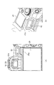
図3は、本実施例の撮像装置(電子機器)としてのデジタルカメラ100におけるタッチバー82の配置位置と内部構成を示した図である。
(Description of Arrangement Position and Internal Configuration of Touch Bar 82)
FIG. 3 is a diagram illustrating an arrangement position and an internal configuration of the
図3に示すように、タッチバー82は、デジタルカメラ100の背面側に接眼部16に隣接して配置されている。
As shown in FIG. 3, the
また、タッチバー82は、サブ電子ダイヤル73、及び右手でグリップ90を握ってカメラを保持した際に親指の位置となる親指待機位置300とも隣接して配置されている。
The
図3の拡大図はタッチバー82の内部構成であり、タッチ操作の検知手段であるタッチセンサ電極302を備えており、タップ操作、左右(図3に示すスライド方向)へのスライド操作が可能である。
The enlarged view of FIG. 3 shows the internal configuration of the
タッチセンサ電極(のタッチ検知面)は、接眼部16側から302a、302b、302cの3つに分割されて配置されている。
The touch sensor electrode (the touch detection surface thereof) is divided into three
ここで本実施例では、タッチセンサ電極(のタッチ検知面)の分割数を3つで説明するが、3つに限定されるものではなく、分割数は、2つ、4つ以上でも良い。 Here, in the present embodiment, the number of divisions of the touch sensor electrode (the touch detection surface thereof) is described as three, but is not limited to three, and the number of divisions may be two, four or more.
図3の拡大図の点線はタッチバー82の外観部品であるキートップ303の外形線である。
The dotted line in the enlarged view of FIG. 3 is the outline of the key top 303 which is an external part of the
また、一点鎖線はタッチセンサ電極302の短辺(Y方向)の中央を通る線分である。
The dashed line is a line segment passing through the center of the short side (Y direction) of the
キートップ外形線303aに内包される領域はタッチセンサ電極302と重畳し、タッチ検出可能な領域とユーザーから認識される第1の操作面である。
An area included in the key
そして、キートップ外形線303aとキートップ外形線303bに内包される領域はタッチセンサ電極302と重畳しない。
A region included in the key
そのため、タッチ検出しない非検出領域とユーザーから認識される第2の操作面である。 Therefore, the second operation surface is recognized by the user as a non-detection region where touch detection is not performed.
キートップ外形線303aに内包される第1の操作面の左右端(X方向端)にはそれぞれくの字形状(矢印形状)の指標303c、303dを設けている。
At the left and right ends (X-direction ends) of the first operation surface included in the key
タッチバー82のスライド方向がユーザーに分かるように示している。
The slide direction of the
また、指標303c、303dは凸または凹形状になっており、ユーザーが親指をタッチバー82に接触させてスライドした際に、左右端がそれぞれ感触でわかるようになっている。
The
本実施例においてキートップ303にタッチ検出しない非検出領域を設けている理由は後述する。 The reason why a non-detection area where no touch is detected is provided in the key top 303 in the present embodiment will be described later.
各タッチセンサ電極はプリント基板301に銅箔等で構成され、プリント基板上の銅箔配線304によりシステム制御部50まで接続される。
Each touch sensor electrode is formed of a copper foil or the like on a printed
前述の通り、システム制御部50は、タッチバー82の出力情報、すなわちタッチセンサ電極302a、302b、302cから入力される情報に基づいて位置座標を算出している。
As described above, the
操作、あるいは状態からタッチバー82上にどのような操作が行なわれたかを判定する。
It is determined from the operation or state what kind of operation has been performed on the
タッチセンサ電極302aはタッチセンサ電極302cよりも相対的に面積が大きくなっており、入力が行いやすくなっている。
The area of the
本実施例においては、タッチセンサ電極302aは約36mm2、タッチセンサ電極302bは約34mm2、タッチセンサ電極302cは約26mm2である。
In this embodiment, the
タッチセンサ電極302cに対してタッチセンサ電極302aは、1.3〜1.4倍の面積に設定されている。
The area of the
また、タッチセンサ電極の大小関係は302a>302b>302cとなるように設定されている。 The magnitude relation of the touch sensor electrodes is set so that 302a> 302b> 302c.
また、タッチセンサ電極302aはキートップ外形線303aで示される第1の操作面より接眼部16側へはみ出した形状である。
Further, the
タッチセンサ電極302aのキートップ外形線303aに内包された領域は第1のタッチ検出領域302a1であり、キートップ外形線303aからはみ出している領域は第2のタッチ検出領域302a2である。
Regions contained in the key
また、キートップ外形線303aとキートップ外形線303bに内包される第2の操作面において、第2のタッチ検出領域302a2と重畳しない領域を第1のタッチ非検出領域とする。
In the second operating surface that is included in the key
タッチセンサ電極302aは親指待機位置300からの距離が遠い。
The
そのため、ユーザーの親指が浮き気味になりやすく、十分なタッチ面積がない場合においても安定した検出を得るために第2のタッチ検出領域302a2を設けることで電極面積を拡大するためである。
Therefore, likely in the user's thumb it floats slightly, in order to enlarge the electrode area by providing a second touch
ただし、第2のタッチ検出領域302a2のはみ出しが大きすぎるとユーザーがキートップ303の第2の操作面を触った場合にもタッチ検出したように誤検知してしまう。
However, thus erroneously detected as touch detection even if the protrusion of the second touch
そのため、タッチセンサ電極302aのはみ出し量がキートップ303のタ第1の操作面の左端と指標303cとの幅303eより大きくならないようにしている。
Therefore, the amount of protrusion of the
この事により、タッチセンサ電極302aは、親指待機位置300からの距離、及び接眼部16への隣接による入力しにくさを相殺して所望の入力しやすさへと調整することが可能である。
Thus, the
この調整によって、位置座標の算出や操作の判定をユーザーの操作意図に対して正確に行えることとなる。 By this adjustment, the calculation of the position coordinates and the determination of the operation can be performed accurately with respect to the operation intention of the user.
また、タッチセンサ電極302cは、サブ電子ダイヤル73近傍がカットされた形状となっている。
The
より具体的には、X軸方向にサブ電子ダイヤル73に近づくに従ってカット領域が大きくなる勾配形状によってタッチセンサ電極302cのカットを行っている。
More specifically, the
そのため、タッチセンサ電極302aはキートップ外形線303aで示される第1の操作面より小さい面積となっており、カット領域を第2のタッチ非検出領域301aとする。
Therefore, the
ただし、タッチセンサ電極302cが第1の操作面より小さすぎると、ユーザーがタッチ検出可能な領域と認識している第1の操作面を触った場合でもタッチ検出しない場合が起きてしまう。
However, if the
そのため、タッチセンサ電極302cがキートップ303のタッチ検出領域の指標303dと半分以上重畳するようにしている。
Therefore, the
この事により、タッチセンサ電極302cは、サブ電子ダイヤル73に対して勢いを付けた操作を行った場合にも意図しない入力が行われにくくなる。
This makes it difficult for the
更に、プリント基板301はタッチセンサ電極302cを狭めたことにより生じた空き領域に位置決め穴305を設けている。
Further, the printed
撮像装置(電子機器)は、第1の操作部材82のタッチ操作面303が配置された背面側の面に設けられた第1の表示部16、27を有している。
The imaging device (electronic device) includes
撮像装置(電子機器)は、第1の操作部材82のタッチ操作面303に対して、タッチ検知面302のスライド操作の方向と直交する方向に設けられた第2の表示部28、29を有している。
The imaging device (electronic device) has
タッチ操作面303は、非導電性である。
The
タッチ検知面302は、タッチ操作面303の内側に配置されている。
The
撮像装置(電子機器)は、タッチ操作面303の周囲を覆うように配置された導電性の外装カバー404、406を有している。
The imaging device (electronic device) has conductive exterior covers 404 and 406 arranged to cover the periphery of the
タッチ検知面は、第1の表示部16側から順に、スライド操作の方向において第1のタッチ検知面302aから第Nのタッチ検知面302nの少なくとも2つの検出面に分割されている。
The touch detection surface is divided into at least two detection surfaces from the first
ユーザが把持する把持部90は、スライド操作の方向において、少なくとも2つのタッチ検知面の中で第Nのタッチ検知面302nに最も近接している。Nは自然数である。
The
図3の場合、N=3である。把持部90は、スライド操作の方向において、第3のタッチ検知面302cに最も近接している。
In the case of FIG. 3, N = 3. The
第2の表示部28は、タッチ操作面303が配置された背面側の面に設けられている。
The
撮像装置100の背面側から見た場合である。
This is a case when viewed from the back side of the
第2の表示部28に表示される第1の操作手段82による操作可能な設定項目のスクロール方向とタッチ操作面303のスライド操作の方向が一致するように、第2の表示部28が配置されている。
The
第2の表示部29は、タッチ操作面303が配置された背面側の面と異なる電子機器100の上面に配置されている。
The
第2の表示部29に表示される第1の操作手段82による操作可能な設定項目のスクロール方向とタッチ操作面303のスライド操作の方向が一致するように、第2の表示部29が配置されている。
The
第2の表示部28は、タッチパネルである。
The
電子機器の背面側から見た場合、第2の表示部28のタッチパネル面のスライド操作の方向とタッチ操作面303のスライド操作の方向が一致するように、第2の表示部28が配置されている。
When viewed from the back side of the electronic device, the
タッチ操作面303のスライド操作の方向において、少なくとも2つのタッチ検知面の中で第Nのタッチ検知面302nに最も近接する位置に、回転操作部材73が設けられている(図3参照)。
In the direction of the slide operation of the
図3は、N=3なので、第3のタッチ検知面302cに最も近接する位置に、回転操作部材(サブ電子ダイヤル)73が設けられている。
In FIG. 3, since N = 3, a rotary operation member (sub electronic dial) 73 is provided at a position closest to the third
電子機器の背面側から見た場合、回転操作部材73の回転方向とタッチ操作面303のスライド操作の方向が一致するように、回転操作部材(サブ電子ダイヤル)73が配置されている。
When viewed from the back side of the electronic device, the rotation operation member (sub electronic dial) 73 is arranged such that the rotation direction of the
電子機器の背面側から見た場合、回転操作部材73を回転操作するユーザの指の軌跡上に第1の操作手段82が配置されている。
When viewed from the back side of the electronic device, the
第1の表示部16、27は、スライド操作の方向においてタッチ操作面303に隣接して配置され、且つ第1の操作部材82のタッチ操作面303に対して背面側に突出した接眼部16である。
The
電子機器の背面側から見た場合、接眼部16に表示される第1の操作手段82による操作可能な設定項目のスクロール方向とタッチ操作面303のスライド操作の方向が一致するように、接眼部16が配置されている。
When viewed from the rear side of the electronic device, the
タッチ検知面302が外装カバー404、406と電気的に絶縁されるように、タッチ検知面302は、外装カバー404、406と離間している。
The
タッチ操作面303は、タッチ検知面302と重畳する第1の操作面303aと、第1の操作面303aの外周に配置され且つタッチ検知面302と重畳しない第2の操作面303bと、を有する。
The
第1の操作面303aと第2の操作面303bとの背面側への突出量及び質感及び色の何れか一つが異なる。
The
第1の操作面303aの質感と第2の操作面303bの質感が異なる。
The texture of the
第1の操作面303aの表面の色と第2の操作面303bの表面の色が異なる。
The color of the surface of the
第1の操作面303aは、第2の操作面303bに比べて電子機器の背面側に突出している。
The
第1の操作面303aの背面側に向かう方向の高さは、把持部90、300の背面側に向かう方向の高さよりも高く、且つ、接眼部16の背面側に向かう方向の高さよりも低い。
The height of the
タッチ操作面303の材質は、ガラスフィラー含有の樹脂である。
The material of the
第1の操作面303aのスライド操作の方向の長さは、電子機器の背面側の面に位置する把持部300のスライド操作の方向の長さよりも長い。
The length of the
また、第1の操作面303aのスライド操作の方向の長さは、回転操作部材73を回転操作する回転操作幅よりも長い。
The length of the
電子機器の背面側から見た場合、スライド操作の方向と直交する方向において、回転操作部材73から順に、第2の操作面303b、第1の操作面303a、第2の操作面303bに配列されている。
When viewed from the back side of the electronic device, in the direction orthogonal to the direction of the slide operation, the
第1の操作面303aのスライド操作の方向と直交する方向の長さは、回転操作部材73のタッチ検知面のスライド操作の方向と直交する方向の長さよりも長い。
The length of the
第2の操作面303bの各々のスライド操作の方向と直交する方向の長さは、回転操作部材73の前記タッチ検知面のスライド操作の方向と直交する方向の長さよりも短い。
The length of the
第1の電極面302aは、第1の操作面303a及び、スライド操作の方向において突出部16側の第1の操作面303aの外縁に隣接して設けられた第2の操作面303bに跨って設けられている。
The
第1の操作面303aは、第2の操作面303bに比べて電子機器の背面側に突出している。
The
電子機器の背面側から見た場合、第1の操作面303aと第1の電極面302aとが重畳する第1のタッチ検出領域は、第2の操作面303bと第1の電極面302aとが重畳する第2のタッチ検出領域よりも広い面積である。
When viewed from the back side of the electronic device, the first touch detection area where the
スライド操作の方向において第1の操作部材(タッチバー)82の操作面に隣接して配置された第2の操作部材(サブ電子ダイヤル)73を有する。 A second operation member (sub electronic dial) 73 is provided adjacent to the operation surface of the first operation member (touch bar) 82 in the slide operation direction.
スライド操作の方向において、第2の操作部材73は、少なくとも2つのタッチ電極面のうち第Nの電極面302nに最も近接している。
In the slide operation direction, the
検知手段302のタッチ電極面の短辺の中点を通るスライド操作の方向に伸びた線分を定義した。 A line segment extending in the direction of the slide operation passing through the midpoint of the short side of the touch electrode surface of the detection means 302 is defined.
その場合、線分を基準として、第Nの電極面302nの第2の操作部材73に近い側の領域を第1の領域とする。
In this case, a region on the side closer to the
第Nの検知面302nの第2の操作部材73に遠い側の領域を第2の領域としたとき、第1の領域の表面積は前記第2の領域の表面積よりも狭い。
When a region of the Nth detection surface 302n that is farther from the
電子機器の背面側から見た場合、第1の操作面303aは、第1の操作面303aとタッチ検知面302が重畳する第1のタッチ検出領域と第1の操作面303aとタッチ検知面302が重畳しない第1のタッチ非検出領域を備えている。
When viewed from the back side of the electronic device, the
第2の操作面303bは、第2の操作面303bとタッチ検知面302が重畳する第2のタッチ検出領域と第2の操作面303bとタッチ検知面302が重畳しない第2のタッチ非検出領域を備えている。
The
電子機器の背面側から見た場合、スライド操作の方向において、突出部16側から順に、第2のタッチ非検出領域、第2のタッチ検出領域、第1のタッチ検出領域に配置されている。
When viewed from the back side of the electronic device, in the direction of the slide operation, the electronic device is arranged in the second non-touch detection region, the second touch detection region, and the first touch detection region in this order from the protruding
第2のタッチ非検出領域のスライド操作の方向の幅は、第2のタッチ検出領域のスライド操作の方向の幅よりも広い。 The width of the second touch non-detection area in the direction of the slide operation is wider than the width of the second touch detection area in the direction of the slide operation.
電子機器の背面側から見た場合、第1の操作面303aと第1の電極面302aとが重畳するタッチ検出領域に第1のタッチ指標303cが設けられている。
When viewed from the back side of the electronic device, a
電子機器の背面側から見た場合、第1の操作面303aと第Nの電極面302nとが重畳するタッチ検出領域に第2のタッチ指標303dが設けられている。
When viewed from the back side of the electronic device, a
第1のタッチ指標303cが第1のタッチ検出領域に設けられている。
The
第2のタッチ検出領域のスライド操作の方向の幅は、第1のタッチ指標303cから第2のタッチ検出領域までの長さ303eよりも短い。
The width of the second touch detection area in the direction of the slide operation is shorter than the length 303e from the
第2のタッチ指標303dは、第1の操作面303aと第Nの電極面302nとが重畳するタッチ検出領域及び第1の操作面303aと第Nの電極面302nとが重畳しないタッチ非検出領域の両方の領域に跨って設けられている。
The
タッチ検出領域に設けられた第2のタッチ指標303dの面積は、タッチ非検出領域に設けられた第2のタッチ指標303dの面積よりも広い。
The area of the
第1の操作部材82は、表示部28の操作面とスライド方向(X方向)に重なり、且つ、表示部28の操作面とスライド方向と直交する方向(Y方向)に重なっていない。
The
電子機器の背面側から見た場合、第1の操作部材82は、表示部28の操作面に対して前面側(Z方向)に凹んだ位置に配置されている。
When viewed from the back side of the electronic device, the
タッチ検知面302の短辺の中点を通るスライド方向に伸びた線分を定義した場合、線分を基準として、第1のタッチ非検出領域の表示部28に遠い側の領域を第1の領域とする。
When a line segment extending in the slide direction passing through the midpoint of the short side of the
第1のタッチ非検出領域の表示部28に近い側の領域を第2の領域としたとき、電子機器の背面側から見た場合、第1の領域のスライド操作の方向と直交する方向の幅は、第2の領域のスライド操作の方向と直交する方向の幅よりも広い。
When a region near the
(タッチバー82の割り当て機能の説明)
この時、ユーザーの操作意図に対して正確に操作判定が行われなければ誤操作となってしまう。
(Description of Assignment Function of Touch Bar 82)
At this time, if the operation determination is not accurately performed for the user's operation intention, an erroneous operation will occur.
しかしながら、タッチバー82の親指の待機位置300からの距離や機器上の他の部材との配置関係によって、意志一致率が下がってしまうことがある。
However, depending on the distance of the thumb of the
例えば、親指待機位置300からの距離によってタッチしやすさが変化してしまう。
For example, the ease of touch varies depending on the distance from the
具体的には、タッチバー82は、親指待機位置300近傍ではタッチしやすく、そこから接眼部16に近傍へと近づくほどに親指を伸ばしていく事になりタッチしにくくなっていく。
Specifically, the
また、接眼部16は、前述の通り内部のEVF29に表示された映像を視認する接眼ファインダーである。
The
しかしながら、快適なアイポイントを確保する目的や接眼状態で鼻が表示部28に接触しにくくする目的のために外装側(背面側)に飛び出した凸形状となっている。
However, it has a convex shape protruding to the exterior side (rear side) for the purpose of securing a comfortable eye point and for the purpose of making it difficult for the nose to contact the
本実施例では、この接眼部16はタッチバー82のタッチ面に対してZ方向に15mm以上飛び出ている。
In the present embodiment, the
このため、タッチバー82は、接眼部16の隣接端へタッチ入力が行いにくくなっている。
For this reason, it is difficult for the
特にスライド操作は、端から端まで入力が行えない場合には設定値の変更段数が減ってしまうためこの影響が顕著である。 In particular, this effect is remarkable when the slide operation cannot be performed from one end to the other end, because the number of setting value change stages decreases.
ここで、本実施例では15mm以上の比較的大きな凸形状を例示したが、およそ1mm以上の凸形状があった場合には操作性への影響が表れてしまうと考えられる。 Here, in the present embodiment, a comparatively large convex shape of 15 mm or more is exemplified, but it is considered that an influence on operability appears when there is a convex shape of approximately 1 mm or more.
また、サブ電子ダイヤル73は、前述の通り回転操作部材であり、右手親指で水平方向(X軸方向)に回転させる事によって複数段階の入力が行えるが、この操作時、隣接するタッチバー82に意図せず触れてしまう可能性がある。
The sub
(タッチバー82の詳細構成について説明)
つぎにタッチバー82の詳細構成について説明する。
(Detailed configuration of
Next, a detailed configuration of the
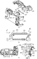
図4(a)はタッチバー82の分解図であり、タッチバー82は外観部品のキートップ303と静電容量方式のタッチ検出を行う電極302を有するプリント基板301から構成されている。
FIG. 4A is an exploded view of the
静電容量方式のタッチ検出方法はユーザーの指がキートップ303に接触した時に変化する静電容量を電極302により検出する。
In the capacitance type touch detection method, the capacitance that changes when a user's finger touches the
そのため、キートップ303は非導電部材で構成される必要がある。 Therefore, the key top 303 needs to be made of a non-conductive member.
また、タッチ検出の反応を向上させるためには静電容量の変化を大きく必要があり、キートップ303の非導電部材の誘電率は高いほうが良い。
Further, in order to improve the response of touch detection, it is necessary to increase the change in capacitance. Therefore, it is preferable that the dielectric constant of the non-conductive member of the
そのため、非導電性の樹脂材料に誘電率の高いガラスフィラーを含有した材料としている。 For this reason, a non-conductive resin material containing a glass filler having a high dielectric constant is used.
図4(a)に示すようにキートップ303はキートップ固定部材401にビス402で固定され、キートップ固定部材401はキートップ303とともにビス403でデジタルカメラ100の上カバー404に固定される。
As shown in FIG. 4A, the
また、キートップ303はビス405によりキートップ固定部材401とともにデジタルカメラ100の背面カバー406に固定される。
The
上カバー404と背面カバー406はデジタルカメラ100の電気ノイズ遮蔽性能を向上させるために導電性の材料で構成される。
The
たとえば、マグネシウム合金や導電樹脂などである。つぎに図4(b)に示すようにキートップ303の裏側にプリント基板301が貼り付けられている。
For example, a magnesium alloy or a conductive resin is used. Next, as shown in FIG. 4B, a printed
キートップ303の裏側にはボス407とリブ408が形成されている。
A
プリント基板301は、位置決め穴305に対してボス407を嵌合させると共にリブ408に押し当てる形でタッチバー82のキートップ303に不図示の両面テープで貼り付けられる。
The printed
この時、両面テープはタッチセンサの検知を阻害しないように50μmから100μm程度の薄手のものを利用する事が好ましい。 At this time, it is preferable to use a thin double-sided tape of about 50 μm to 100 μm so as not to hinder the detection of the touch sensor.
この事により、操作面としてのキートップ303に対してプリント基板301及びそれに配線させるタッチセンサ電極を限られた領域かつタッチセンサ電極に近い位置で精度良く取り付ける事が可能となる。
This makes it possible to accurately attach the printed
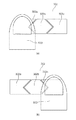
つぎに図4(c)はタッチバー82の断面図を示している。
Next, FIG. 4C shows a cross-sectional view of the
上述したように、キートップ303はキートップ外形線303aに内包されるタッチ検出領域とキートップ外形線303aとキートップ外形線303bに内包されるタッチ非検出領域を有している。
As described above, the
キートップ外形線303aの内側を第1の操作面とし、キートップ外形線303aの外側で、キートップ外形線303bの内側を第2の操作面とする(図3参照)。
The inside of the key
キートップ外形線303aの内側の第1の操作面とタッチセンサ電極と重畳する面を第1のタッチ検出領域、キートップ外形線303aの内側の第1の操作面とタッチセンサ電極と重畳しない面を第1のタッチ非検出領域とする。
A surface that overlaps the first operation surface inside the key
第1の操作面の外周を第2の操作面が取り囲んでいる(図3参照)。 The outer periphery of the first operation surface is surrounded by the second operation surface (see FIG. 3).
第2の操作面とタッチセンサ電極と重畳する面を第2のタッチ検出領域、第2の操作面とタッチセンサ電極と重畳しない面を第2のタッチ非検出領域とする(図3参照)。 A surface that overlaps the second operation surface and the touch sensor electrode is a second touch detection region, and a surface that does not overlap the second operation surface and the touch sensor electrode is a second touch non-detection region (see FIG. 3).
撮像装置の背面に配置された平面である第1の操作面は、第1の操作面の外周を取り囲んだ第2の操作面よりも背面側に突出している。 The first operation surface, which is a plane disposed on the back surface of the imaging device, protrudes more rearward than the second operation surface surrounding the outer periphery of the first operation surface.
つまり、第1の操作面は、第2の操作面よりも背面側に高い位置に面が存在している。 That is, the first operation surface has a surface at a position higher on the back side than the second operation surface.
これは、導電材料で構成される上カバー404および背面カバー406とタッチセンサ電極302との間に一定の距離を設けないとタッチ検出の静電容量が導電材料へ放出されてタッチ検出の出力が低下してしまうためである。
This is because, unless a certain distance is provided between the
図4(c)にタッチセンサ電極302と上カバー404および背面カバー406とのクリアランス409、410を示す。
FIG. 4C shows
本実施例のタッチセンサ電極302においては少なくとも1mm以上のクリアランスを設けることでタッチ検出に必要な出力を得られている。
In the
以上の理由からキートップ303はタッチ非検出領域を全周に有している。
For the above reasons, the
しかしながらが、ユーザーがEVF29を覗きながらタッチバー82のタッチ操作を行った場合は、ブラインド操作になるためタッチ検出領域とタッチ非検出領域の判別ができない。
However, when the user performs a touch operation on the
そのため、図4(c)に示すようにキートップ303のタッチ検出領域はタッチ非検出領域に対し凸形状411とし、タッチ非検出領域は凹面形状412とすることでブラインドによるタッチ操作を可能としている。
Therefore, as shown in FIG. 4C, the touch detection area of the
本実施例においては、タッチ検出領域(第1の操作面)の凸面形状411の高さは凹面形状412に対し1mm高い。
In the present embodiment, the height of the convex shape 411 of the touch detection area (first operation surface) is 1 mm higher than the
ユーザーが親指待機位置300を把持した場合に、容易にタッチ検出の誤操作をしないように親指待機位置300の面よりZ方向で高くしている。
When the user holds the
また、ユーザーが接眼部16のEVF29を覗いたときに容易にタッチ検出の誤操作をしないようにタッチ検出領域の凸形状411の高さは接眼部16の面よりZ方向で低くしている。
In addition, the height of the convex shape 411 of the touch detection area is set lower in the Z direction than the surface of the
また、キートップ303のタッチ検出領域の表面はタッチ非検出領域に対し、滑らかな質感とし、タッチ非検出領域の表面はざらつく質感とすることで判別ができるようにしている。
The surface of the touch detection area of the
また、キートップ303のタッチ検出領域の表面の色をタッチ非検出領域に対して異ならせることでタッチ検出領域の視認性を上げている。
Further, the color of the surface of the touch detection area of the
(サブ電子ダイヤル73の説明)
図1(b)、図4(a)のように、サブ電子ダイヤル73は、タッチバー82のタッチ面401に対して撮像装置の前面側(Z方向)に凹んだ位置に設けられている。
(Description of sub electronic dial 73)
As shown in FIGS. 1B and 4A, the sub
しかしながら、タッチバー82のタッチ面401と右手親指でサブ電子ダイヤル73を回動する接触面のZ方向の段差は小さい。
However, the step in the Z direction between the
よって、サブ電子ダイヤル73の操作時、隣接するタッチバー82に意図せず触れてしまう可能性がある。
Therefore, when the sub
図1(b)、図4(a)の本実施例では、タッチバー82のタッチ面401に対して撮像装置の前面側(Z方向)に凹んだ位置に設けられている。
1B and 4A, the touch bar is provided at a position recessed on the front surface side (Z direction) of the imaging apparatus with respect to the
しかし、逆に、タッチバー82のタッチ面401に対して撮像装置の背面側(Z方向)に突出した位置に設けられている形態も本発明に含まれる。
However, conversely, a form provided at a position protruding from the
タッチバー82のタッチ面401と右手親指でサブ電子ダイヤル73を回動する接触面の背面側(Z方向)に突出する段差が小さい。
The step that projects to the rear side (Z direction) of the contact surface on which the sub
よって、サブ電子ダイヤル73の操作時、隣接するタッチバー82に意図せず、右手親指が触れてしまう可能性があるためである。
Therefore, when operating the sub
サブ電子ダイヤル73は、Y方向を回転軸として、X方向に一軸に回転される回転操作部材である。
The sub
撮像装置(電子機器)の背面側から見た場合、第1の操作部材としてのタッチバー82は、表示部としてのタッチパネル28の操作面とスライド方向(X方向)に重なっている。
When viewed from the back side of the imaging device (electronic device), the
そして、第1の操作部材としてのタッチバー82は、表示部としてのタッチパネル28の操作面とスライド方向と直交する方向(Y方向)に重なっていない。
The
撮像装置(電子機器)の背面側から見た場合、タッチバー82は、タッチパネル28の操作面に対して前面側(Z方向)に凹んだ位置に配置されている。
When viewed from the back side of the imaging device (electronic device), the
しかしながら、タッチバー82の操作面(タッチ面)とタッチパネル28の操作面(タッチ面)のZ方向の段差は比較的大きくなっている。
However, the step in the Z direction between the operation surface (touch surface) of the
よって、タッチパネル28の操作時、隣接するタッチバー82に意図せず、指が触れてしまう可能性は低い。
Therefore, when operating the
本実施例では、タッチバー82のタッチ面とタッチパネル28のタッチ面のZ方向の段差は、タッチバー82のタッチ面401とサブ電子ダイヤル73を回動する接触面のZ方向の段差よりも大きくなっている。
In the present embodiment, the step in the Z direction between the touch surface of the
検知手段としてのタッチセンサ電極302のタッチ検知面の短辺の中点を通るスライド方向に伸びた線分A(図3)を定義する。
A line segment A (FIG. 3) extending in the slide direction passing through the midpoint of the short side of the touch detection surface of the
その場合、線分A(中心線)を基準として、第Nのタッチ検知面302nの第2の操作部材73に近い側の領域を第1の領域とする。
In this case, with the line segment A (center line) as a reference, the area on the side closer to the
そして、第Nのタッチ検知面302nの表示部(タッチパネル)28に近い側の領域を第2の領域としたとき、第1の領域の表面積は第2の領域の表面積よりも狭くなっている。 When the area on the side of the Nth touch detection surface 302n closer to the display unit (touch panel) 28 is the second area, the surface area of the first area is smaller than the surface area of the second area.
(リニアリティの説明)
図3(b)に示す本実施例のタッチセンサ電極302においては、タッチセンサ電極302bから隣り合うタッチセンサ電極302a、及び302cに対して、くの字の勾配形状が形成されている。
(Explanation of linearity)
In the
このことによりスライド操作を行った際にタッチセンサ電極の静電容量の入力値が徐々に隣の電極へと移っていきリニアリティを確保した操作が行える。 Thus, when the slide operation is performed, the input value of the capacitance of the touch sensor electrode gradually shifts to the adjacent electrode, and an operation can be performed while ensuring linearity.
図3(b)に示す本実施例のタッチセンサ電極302においては、くの字の勾配形状の頂点がタッチセンサ電極302のY方向略中央に配置されており、かつ頂点の角度Θ1及びΘ2が略90度に設定されている。
In the
つぎに図5にキートップ303と隣接するサブ電子ダイヤル73および親指待機位置300とのサイズ関係を示す。
Next, FIG. 5 shows the size relationship between the
図5(a)に示すようにX方向幅は親指待機位置300のX方向幅L1に対してサブ電子ダイヤル73のX方向幅L2およびキートップ303のタッチ検出領域のX方向幅L3はL1<L2、L2≦L3となる。
As shown in FIG. 5A, the X-direction width L1 of the sub
たとえば親指待機位置300のX方向幅L1は、日本人の親指の幅の平均が約20mmであり、その4分の1の10mmが親指待機位置300との把持する場合の接触面積と想定すると5mm以上必要である。
For example, the X-direction width L1 of the
サブ電子ダイヤル73やタッチバー82を操作する場合は、親指の接触面積に対して2倍以上のスライド距離がないと、1回のスライド操作における設定値の変更幅が小さくなってしまう。
When operating the sub
そのため、繰り返しスライド動作を行わなければならない。 Therefore, the slide operation must be repeatedly performed.
そのため、少なくともサブ電子ダイヤル73のX方向幅L2およびキートップ303のタッチ検出領域のX方向幅L3は10mm以上必要である。
Therefore, at least the X-direction width L2 of the sub
また、タッチバー82はサブ電子ダイヤル73に対して同等のスライド操作性を持たせる。
Further, the
そのために、キートップ303のタッチ検出領域のX方向幅L3は、サブ電子ダイヤル73のX方向幅L2と同等以上の長さである必要がある。
Therefore, the width L3 of the touch detection area of the key top 303 in the X direction needs to be equal to or greater than the width L2 of the sub
また、図5(b)に示すようにサブ電子ダイヤル73のY方向幅H1およびキートップ303のタッチ検出領域のY方向幅H2およびタッチ非検出領域のY方向幅H3はH1≦H2、H1>H3となる。
Further, as shown in FIG. 5B, the width H1 of the sub
上述したように、タッチバー82はサブ電子ダイヤル73に対して同等のスライド操作性を持たせる、
そのためにキートップ303のタッチ検出領域のY方向幅H2は少なくともサブ電子ダイヤル73のY方向幅H1よりも同等以上にする必要がある。
As described above, the
Therefore, the Y direction width H2 of the touch detection area of the key top 303 needs to be at least equal to or greater than the Y direction width H1 of the sub
また、キートップ303のタッチ非検出領域のY方向幅H3は検出領域と誤認識されないために少なくともサブ電子ダイヤル73のY方向幅H1よりも小さくする必要がある。
Further, the width H3 in the Y direction of the touch non-detection area of the key top 303 must be at least smaller than the width H1 in the Y direction of the sub
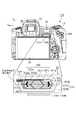
図6(a)はユーザーがデジタルカメラ100を把持した状態をデジタルカメラ100の上面から見た図であり、図6(b)は背面から見た図である。
FIG. 6A is a diagram of a state in which the user holds the
図6(a)に示すように親指待機位置300は、一般的にグリップ90を背面側に投影した位置に存在し、ラバー等を貼付する事でその位置を示すと共にグリップ感を高めている事が多い。
As shown in FIG. 6A, the
また、図6(b)に示すようにタッチバー82とサブ電子ダイヤル73の位置関係は、親指待機位置300を中心に親指の回転軌跡上に配置することでグリップ90を握りながらタッチバー82とサブ電子ダイヤル73を操作できるようになっている。
As shown in FIG. 6B, the positional relationship between the
サブ電子ダイヤル73の回転方向とタッチバー82のスライド操作の方向は親指の回転軌跡に合わせて、図6(b)のX方向と一致にしており、タッチバー82とサブ電子ダイヤル73の操作性を同一にしている。
The rotation direction of the sub
また、タッチバー82は、親指待機位置300に隣接する。
The
よって、前述の通りグリップ部90を握った状態で右手の親指でタップ操作、左右(図3に示すスライド方向)へのスライド操作などが行いやすい配置となっている。
Therefore, as described above, the arrangement is such that the tap operation with the thumb of the right hand and the slide operation to the left and right (sliding direction shown in FIG. 3) can be easily performed while holding the
タッチバー82は、操作に応じてそれぞれ機能を割り当てる事が可能である。 A function can be assigned to each of the touch bars 82 according to an operation.
例えば、操作部材のメイン電子ダイヤル71やサブ電子ダイヤル73で設定可能な露出関係の設定値を変更する機能を割り当てることができる。
For example, a function of changing the exposure-related set value that can be set with the main
露出関係の設定値はシャッター速度(Tv)や絞り値(Av)、ISO感度、オート露出モード時の露出補正値である。 The set value of the exposure relation is a shutter speed (Tv), an aperture value (Av), an ISO sensitivity, and an exposure correction value in an auto exposure mode.
例えば、ISO感度設定の機能をタッチバー82に割り当てた場合を説明する。
For example, a case in which the function of setting the ISO sensitivity is assigned to the
タッチバー82の左半分の位置においてタップ操作が行われた場合には、デジタルカメラ100の撮影ISO感度を1/3段低感度に設定する機能操作が行われた場合には、撮影ISO感度を1/3段高感度に設定する機能が割り当てられる。
When a tap operation is performed at the left half position of the
右半分の位置座標においてタップ操作が行われた場合には、撮影ISO感度を1/3段高感度に設定する機能が割り当てられる。 When a tap operation is performed at the right half position coordinates, a function of setting the shooting ISO sensitivity to 1 / 3-step high sensitivity is assigned.
また、スライド操作が行われた場合には、デジタルカメラ100の撮影ISO感度をスライドの1段階毎に1/3段ずつ増減する機能が割り当てられる。
In addition, when a slide operation is performed, a function of increasing or decreasing the shooting ISO sensitivity of the
これらの割り当てられる機能はユーザーによってカスタマイズ可能であり、例えば、左半分の位置においてタップ操作が行われた場合には、デジタルカメラ100の撮影ISO感度を自動設定にする機能を割り当てるといった変更が可能である。
These assigned functions can be customized by the user. For example, when a tap operation is performed at the left half position, a change to assign a function of automatically setting the shooting ISO sensitivity of the
右半分の位置座標においてタップ操作が行われた場合には、撮影ISO感度を最高ISO感度に設定する機能を割り当てるといった変更が可能である。 When the tap operation is performed at the right half position coordinates, a change such as assigning a function of setting the photographing ISO sensitivity to the highest ISO sensitivity is possible.
また、タッチバー82は、露出関係の設定値以外にもホワイトバランス設定、AFモード、ドライブモードの設定、再生画像送りが割り当て可能である。
The
また、動画撮影モード時にはマイクの録音レベル調整や動画再生の早送りや逆戻し機能を割り当てすることができる。 In addition, in the moving image shooting mode, a function for adjusting the recording level of the microphone and a function of fast-forwarding and reversing the reproduction of the moving image can be assigned.
上述したようにタッチバー82はさまざまな機能を操作可能であるが、タッチバー82に設定されたさまざまな機能を把握して操作するためには、デジタルカメラ100に配置された表示画面を見ながら操作する必要がある。
As described above, the
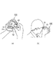
図7(a)ではカメラ背面に設けられた表示部28やカメラ上面に設けられたファインダー外表示部43を見ながらタッチバー82をユーザーが操作する概略図を示している。
FIG. 7A shows a schematic diagram in which the user operates the
また、図7(b)には接眼ファインダー内のEVF29を見ながらタッチバー82をユーザーが操作する概略図を示している。
FIG. 7B is a schematic diagram of a user operating the
図7のように複数の表示部を有するカメラの場合、ユーザーはさまざまなスタイルで撮影や撮影機能の設定を行うため、タッチバー82はどの表示部を見ながらでも操作しやすい位置に配置する必要がある。 In the case of a camera having a plurality of display units as shown in FIG. 7, the user performs shooting in various styles and sets shooting functions. is there.
図8は本発明の特徴である複数の表示部とタッチバー82との位置関係を示した概略図である。
FIG. 8 is a schematic diagram showing a positional relationship between a plurality of display units and the
図8(a)はカメラ背面に設けられた表示部28と接眼ファインダー内のEVF29との位置関係を、図8(b)はカメラ上面に設けられたファインダー外表示部43との位置関係を示している。
FIG. 8A shows a positional relationship between the
図8(a)に示すようにタッチバー82は表示部28の上辺28aとEVF29の右辺29aとそれぞれ隣接するように配置されている。
As shown in FIG. 8A, the
また、図8(b)に示すようにタッチバー82はファインダー外表示部43の下辺43aと隣接するように配置されている。
In addition, as shown in FIG. 8B, the
このように各表示部に囲われるようにタッチバー82を配置することで、図7に示すようにどの表示部を見ながらでも各表示画面とタッチ操作を把握しながらタッチバー82を操作することができる。
By arranging the
とくにプロカメラマンやハイアマチュアといわれるカメラユーザーはEVF29やファインダー外表示部43を見ながら素早く撮影設定をすることが多い。
Particularly, a professional photographer or a camera user who is called a high amateur often quickly sets shooting while looking at the
そのため、本発明のタッチバー82の配置であると表示部を覗きこむ動作とタッチ操作を一連の動作で行うことができる。
Therefore, with the arrangement of the
つぎに図9は各表示部の表示画面とタッチバー82のスライド方向との関係を示した概略図である。図9(a)は露出関係の撮影設定値が表示された各表示画面を示している。
Next, FIG. 9 is a schematic diagram showing the relationship between the display screen of each display unit and the sliding direction of the
カメラ背面に設けられた表示部28には表示画面下部28bに撮影設定値がX方向に並んで配置されている。
On the
一般的に撮影画像はX方向に長い(横長)サイズであり、長辺と短辺の比率(アスペクト比)は3:2か4:3である。 Generally, a captured image is long (horizontally long) in the X direction, and the ratio (aspect ratio) of the long side to the short side is 3: 2 or 4: 3.
そのため、撮像された画像の再生表示やLV表示を行う表示部28とEVF29は、撮影画像のアスペクト比に合わせてX方向に長い。
For this reason, the
表示部28は図9(a)のようにLV表示時に被写体像と表示が被らないように、かつ撮影設定値をすべて一列に表示するために設定値を表示画面下部28bにX方向に並べて配置している。
The
とくにマニュアル露出モード時の測光値やオート露出モード時の補正値を示す露出メーター28cは長い表示幅であるため、Y方向に並べて表示するには不向きである。
In particular, since the
露出メーター28cの測光値や補正値を示す露出メーターカーソル28dは設定値が変更されるとメーター上をX方向にスクロールする。
When the set value is changed, the
本発明においては設定値のカーソル移動やスライドによる設定値の表示切り替えをスクロールとし、その方向をスクロール方向と定義する。 In the present invention, scrolling is used to switch the display of the set value by moving the cursor or sliding the set value, and that direction is defined as the scroll direction.
設定変更可能な設定値は設定値選択カーソル28eにより選択されており、操作部材のメイン電子ダイヤル71やサブ電子ダイヤル73、タッチバー82によりカーソル選択されている設定を変更可能である。
The set value whose setting can be changed is selected by the set
EVF29の表示画面は表示部28と同様に表示画面下部29bに露出メーター29cと露出メーターカーソル29dを含む各設定値と設定値選択カーソル29eをX方向に並べて表示されている。
On the display screen of the
ファインダー外表示部43は撮影画像を表示せず各設定値のみ表示するため、各設定値と設定値選択カーソル43eは横並びには表示されない。
Since the
ただし、ファインダー外表示部43の露出メーター43cと露出メーターカーソル43dの表示方向は表示部28やEVF29の露出メーターに合わせてX方向としている。
However, the display directions of the
よってタッチバー82をスライド操作でオート露出モード時の露出補正値を変更した場合は、各表示部の露出メーターの露出メーターカーソルはX方向にスクロールする。
Therefore, when the exposure correction value in the automatic exposure mode is changed by sliding the
また、マニュアル露出モード時にタッチバー82によってシャッター速度(Tv)や絞り値(Av)、ISO感度を変更した場合も、各表示部の露出メーターの露出メーターカーソルはX方向にスクロールする。
Also, when the shutter speed (Tv), aperture value (Av), and ISO sensitivity are changed by the
そのため、タッチバー82のスライド操作方向を露出メーターカーソルのスクロール方向と同一とすることでユーザーは露出メーターカーソル移動と関連付けてスライド操作を行うことが可能である。
Therefore, by making the slide operation direction of the
図9(b)ではISO感度をタッチバー82で変更した場合の概略図を示している。
FIG. 9B is a schematic diagram when the ISO sensitivity is changed by the
各表示部の設定値選択カーソル(28e、29e、43e)はISO感度の項目を選択した状態であり、タッチバー82にて設定変更可能である。
The setting value selection cursors (28e, 29e, 43e) of each display section are in a state where the item of ISO sensitivity is selected, and the setting can be changed by the
ユーザーがタッチバー82に親指を接触させ、スライド操作を開始すると、表示部28とEVF29にISO感度メーター28fと29fがそれぞれ表示される。
When the user touches the
ユーザーはタッチバー82上の親指をX方向右側にスライドさせていくとISO感度メーター28f、29fの表示はX方向右側にスクロールされ、ISO感度はISO100からISO400へ変更される。
When the user slides the thumb on the
そしてISO感度の変更に合わせて露出値が2段上がるため、各表示部の露出メーターの露出メーターカーソル(28d、29d、43d)はX方向右側にスクロールする。 Then, since the exposure value increases by two steps in accordance with the change in the ISO sensitivity, the exposure meter cursors (28d, 29d, 43d) of the exposure meters on the respective display units scroll rightward in the X direction.
タッチバー82でシャッター速度(Tv)や絞り値(Av)を変更した場合も同様に、各設定値のメーターが表示されX方向にスクロールする。
Similarly, when the shutter speed (Tv) or the aperture value (Av) is changed by the
以上のように、各表示部の露出メーターカーソルや各設定値のメーター表示のスクロール方向とタッチバー82のスライド操作方向を同一とする。
As described above, the scroll direction of the exposure meter cursor of each display unit and the meter display of each set value and the slide operation direction of the
よって、ユーザーは各表示部を見ながら直感的にタッチバー82で様々な設定変更を行うことができる。
Therefore, the user can intuitively change various settings with the
本実施例ではタッチバー82のスクロール方向はX方向であるが各表示部に表示される設定値の各設定値のメーター表示のスクロール方向と同一であればよいため、X方向に限定されるものではない。
In the present embodiment, the scroll direction of the
また、本実施例はEVF29においてタッチバー82との位置関係を説明した。
In this embodiment, the positional relationship between the
それに限定されず、ミラーとペンタプリズムと焦点板を有した光学ファインダーにおける焦点板に重畳した透過型の液晶表示部でも実施可能であり、EVF29を有する接眼ファインダーに限定されるものではない。
However, the present invention is not limited to this, and the present invention can also be implemented in a transmission type liquid crystal display unit superimposed on a focusing screen in an optical viewfinder having a mirror, a pentaprism, and a focusing screen, and is not limited to an eyepiece viewfinder having an
例えば、ここまで、タッチセンサ電極の大きさに関しては平面的な表面積として捉えて説明してきたが、曲面形状や凹凸形状といった立体的な形状として捉えて入力しやすさを調整しても良い。 For example, although the size of the touch sensor electrode has been described above as a planar surface area, the touch input may be adjusted as a three-dimensional shape such as a curved surface shape or an uneven shape.
以上、本発明の好ましい実施形態について説明したが、本発明はこれらの実施形態に限定されず、その要旨の範囲内で種々の変形及び変更が可能である。 Although the preferred embodiments of the present invention have been described above, the present invention is not limited to these embodiments, and various modifications and changes can be made within the scope of the gist.
本発明の電子機器は、撮像装置であるデジタルカメラに限定されない。複写機、レーザービームプリンタ(LBP)、インクジェットプリンタにも適用できる。 The electronic device of the present invention is not limited to a digital camera that is an imaging device. The present invention can be applied to a copying machine, a laser beam printer (LBP), and an ink jet printer.
モニターを把持しながら、タッチ操作/スライド操作でコピー枚数や、コピー用紙のサイズ、を変更するタッチ操作面に本発明のタッチバーを用いても良い。 The touch bar of the present invention may be used on a touch operation surface for changing the number of copies or the size of copy paper by a touch operation / slide operation while holding the monitor.
また、スマートフォン、タブレットコンピュータ、スマートウォッチ、等の携帯可能な小型のコンピューターであるモバイルにも適用できる。 In addition, the present invention can be applied to a mobile that is a small portable computer such as a smartphone, a tablet computer, and a smart watch.
モバイルの画面外に本発明のタッチバーを配置して、画像送り、選択などのタッチ操作/スライド操作を可能とできる。 By disposing the touch bar of the present invention outside the screen of the mobile device, it is possible to perform a touch operation / slide operation such as image feed and selection.
他にも、自動車、医療機器、ゲームにも適用できる。 In addition, it can be applied to automobiles, medical devices, and games.
自動車のステアリング部に本発明のタッチバーを配置して、ハンドル操作を行いながら、タッチ操作によるメニュー切り替えや、スライド操作による音量の微調整、カーナビ画面の縮小/拡大などが可能とできる。 By arranging the touch bar of the present invention on the steering portion of the automobile, it is possible to perform menu switching by touch operation, fine adjustment of volume by slide operation, reduction / enlargement of the car navigation screen, etc. while operating the steering wheel.
また、医療機器として、ハンディーX線の把持部に本発明のタッチバーを配置して、スライドにより操作の微調整が可能とできる。 Further, as a medical device, the touch bar of the present invention can be arranged on a handy X-ray holding portion, and the operation can be finely adjusted by sliding.
28 表示部
29 EVF
43 ファインダー外表示部
73 サブ電子ダイヤル
82 タッチバー
301 フレキシブルプリント配線板
302a1 第1のタッチ検出領域
302a2 第2のタッチ検出領域
303 電極
404 上カバー
406 背面カバー
28
43
Claims (6)
前記タッチ検知面は、前記スライド操作の方向において、第1の電極面から第Nの電極面の少なくとも2つの電極面に分割され、
前記タッチ検知面が前記外装カバーと電気的に絶縁されるように、前記タッチ検知面は、前記外装カバーと離間しており、
前記電子機器の背面側から見た場合、前記タッチ操作面は、前記タッチ検知面と重畳するタッチ検出領域と、前記タッチ検出領域の外周に配置され且つ前記タッチ検知面と重畳しないタッチ非検出領域と、を備え、
前記タッチ検出領域と前記タッチ非検出領域との背面側への突出量及び質感及び色の何れか一つが異なることを特徴とする電子機器。 A first operation unit having a non-conductive touch operation surface on which a touch operation and a slide operation are performed; a touch detection surface arranged inside the touch operation surface to detect the touch operation; and a periphery of the touch operation surface And a conductive outer cover arranged to cover the electronic device, comprising:
The touch detection surface is divided into at least two electrode surfaces from a first electrode surface to an Nth electrode surface in the direction of the slide operation;
The touch detection surface is separated from the exterior cover so that the touch detection surface is electrically insulated from the exterior cover,
When viewed from the back side of the electronic device, the touch operation surface is a touch detection region that overlaps the touch detection surface, and a touch non-detection region that is arranged around the touch detection region and does not overlap the touch detection surface. And
An electronic device, wherein the touch detection area and the touch non-detection area are different from each other in one of a protruding amount, a texture, and a color on a rear side.
前記接眼部は、前記スライド操作の方向において、前記少なくとも2つの電極面の中で前記第1の電極面に最も近接して配置され、
前記把持部は、前記スライド操作の方向において、前記少なくとも2つの電極面の中で前記第Nの電極面に最も近接して配置され、
前記タッチ検出領域の背面側に向かう方向の高さは、前記把持部の背面側に向かう方向の高さよりも高く、且つ、前記接眼部の背面側に向かう方向の高さよりも低い請求項1又は2に記載の電子機器。 An eyepiece protruding rearward with respect to the touch operation surface, and a gripper gripped by a user,
The eyepiece is disposed closest to the first electrode surface among the at least two electrode surfaces in the direction of the slide operation,
The grip portion is disposed closest to the N-th electrode surface among the at least two electrode surfaces in the direction of the slide operation,
The height of the touch detection region in the direction toward the back side is higher than the height of the grip portion in the direction toward the back side, and is lower than the height in the direction toward the back side of the eyepiece. Or the electronic device according to 2.
前記タッチ検出領域のスライド操作の方向の長さは、前記電子機器の背面側の面に位置する把持部のスライド操作の方向の長さよりも長く、且つ、前記回転操作部材を回転操作する回転操作幅よりも長い請求項1乃至4の何れか一項に記載の電子機器。 In the direction of the slide operation, a rotation operation member is provided at a position closest to the N-th electrode surface among the at least two electrode surfaces,
The length of the touch detection area in the direction of the slide operation is longer than the length of the gripping portion located on the rear surface of the electronic device in the direction of the slide operation, and the rotation operation of rotating the rotation operation member is performed. The electronic device according to claim 1, wherein the electronic device is longer than the width.
前記タッチ検出領域のスライド操作の方向と直交する方向の長さは、前記回転操作部材の前記タッチ検知面のスライド操作の方向と直交する方向の長さよりも長く、且つ、前記タッチ非検出領域の各々のスライド操作の方向と直交する方向の長さは、前記回転操作部材の前記タッチ検知面のスライド操作の方向と直交する方向の長さよりも短い請求項5に記載の電子機器。 When viewed from the back side of the electronic device, in a direction orthogonal to the direction of the slide operation, the touch operation surface is, in order from the rotary operation member, the touch non-detection area, the touch detection area, and the touch non-detection. Are arranged in regions,
The length of the touch detection area in the direction orthogonal to the direction of the slide operation is longer than the length of the rotary operation member in the direction orthogonal to the direction of the slide operation of the touch detection surface, and the length of the touch non-detection area. The electronic device according to claim 5, wherein a length in a direction orthogonal to a direction of each slide operation is shorter than a length in a direction orthogonal to the direction of the slide operation of the touch detection surface of the rotary operation member.
Priority Applications (2)
| Application Number | Priority Date | Filing Date | Title |
|---|---|---|---|
| JP2018125513A JP7071234B2 (en) | 2018-06-29 | 2018-06-29 | Electronics |
| US16/455,365 US11010000B2 (en) | 2018-06-29 | 2019-06-27 | Electronic equipment having a touch operating member that can be operated while viewing display monitors |
Applications Claiming Priority (1)
| Application Number | Priority Date | Filing Date | Title |
|---|---|---|---|
| JP2018125513A JP7071234B2 (en) | 2018-06-29 | 2018-06-29 | Electronics |
Publications (2)
| Publication Number | Publication Date |
|---|---|
| JP2020003734A true JP2020003734A (en) | 2020-01-09 |
| JP7071234B2 JP7071234B2 (en) | 2022-05-18 |
Family
ID=69007573
Family Applications (1)
| Application Number | Title | Priority Date | Filing Date |
|---|---|---|---|
| JP2018125513A Active JP7071234B2 (en) | 2018-06-29 | 2018-06-29 | Electronics |
Country Status (2)
| Country | Link |
|---|---|
| US (1) | US11010000B2 (en) |
| JP (1) | JP7071234B2 (en) |
Families Citing this family (1)
| Publication number | Priority date | Publication date | Assignee | Title |
|---|---|---|---|---|
| JP6647348B2 (en) * | 2018-06-29 | 2020-02-14 | キヤノン株式会社 | Electronics |
Citations (7)
| Publication number | Priority date | Publication date | Assignee | Title |
|---|---|---|---|---|
| JP2002116880A (en) * | 2000-10-11 | 2002-04-19 | Sony Corp | Input device and electronic equipment having the same device |
| JP2008236765A (en) * | 2008-03-31 | 2008-10-02 | Fujifilm Corp | Mobile electronic device |
| JP2009164757A (en) * | 2007-12-28 | 2009-07-23 | Victor Co Of Japan Ltd | Image display apparatus and imaging apparatus |
| JP2010004217A (en) * | 2008-06-19 | 2010-01-07 | Casio Comput Co Ltd | Electronic device, operation assistance method, and program |
| JP2010165149A (en) * | 2009-01-15 | 2010-07-29 | Victor Co Of Japan Ltd | Electronic apparatus and operation control method using touch sensor |
| JP2013016069A (en) * | 2011-07-05 | 2013-01-24 | Dainippon Printing Co Ltd | Transparent electrode sensor for touch panel, touch panel, filament bundle for transparent electrode sensor, and fabric for transparent electrode sensor |
| JP2013242767A (en) * | 2012-05-22 | 2013-12-05 | Tokai Rika Co Ltd | Input apparatus |
Family Cites Families (36)
| Publication number | Priority date | Publication date | Assignee | Title |
|---|---|---|---|---|
| US5548306A (en) * | 1994-04-28 | 1996-08-20 | At&T Global Information Solutions Company | Visible and touchable touch screen shield |
| JP4127982B2 (en) * | 2001-05-28 | 2008-07-30 | 富士フイルム株式会社 | Portable electronic devices |
| US6972749B2 (en) * | 2001-08-29 | 2005-12-06 | Microsoft Corporation | Touch-sensitive device for scrolling a document on a display |
| US20070097090A1 (en) * | 2005-10-31 | 2007-05-03 | Battles Amy E | Digital camera user interface |
| JP5013798B2 (en) * | 2005-11-11 | 2012-08-29 | 旭ファイバーグラス株式会社 | Glass filler for polycarbonate resin and polycarbonate resin composition |
| US9335868B2 (en) * | 2008-07-31 | 2016-05-10 | Apple Inc. | Capacitive sensor behind black mask |
| JP5410887B2 (en) * | 2008-09-11 | 2014-02-05 | パナソニック株式会社 | Display device and imaging device |
| US8218069B2 (en) * | 2008-09-19 | 2012-07-10 | Panasonic Corporation | Camera body with which various flash devices can be interchangeably used |
| JP5446626B2 (en) * | 2009-09-07 | 2014-03-19 | ソニー株式会社 | Sensor device and information processing device |
| JP5306266B2 (en) * | 2010-03-15 | 2013-10-02 | キヤノン株式会社 | Imaging apparatus and control method thereof |
| JP2012010061A (en) | 2010-06-24 | 2012-01-12 | Nikon Corp | Imaging apparatus |
| TW201216130A (en) * | 2010-10-06 | 2012-04-16 | Univ Nat Cheng Kung | Interface system of image-capturing device |
| TWI471774B (en) * | 2011-09-30 | 2015-02-01 | Wintek Corp | Touch-sensitive device and touch-sensitive display device |
| FR2990020B1 (en) * | 2012-04-25 | 2014-05-16 | Fogale Nanotech | CAPACITIVE DETECTION DEVICE WITH ARRANGEMENT OF CONNECTION TRACKS, AND METHOD USING SUCH A DEVICE. |
| KR101515623B1 (en) * | 2012-05-14 | 2015-04-28 | 삼성전자주식회사 | Method and apparatus for operating functions of portable terminal having bended display |
| JP2013250900A (en) * | 2012-06-01 | 2013-12-12 | Sony Corp | Information processing apparatus and method of manufacturing the same |
| CN104396230B (en) * | 2012-06-29 | 2017-03-01 | 富士胶片株式会社 | Photographing unit and its method of controlling operation |
| KR101932164B1 (en) * | 2012-07-17 | 2019-03-21 | 삼성디스플레이 주식회사 | touch screen panel and display device with the same |
| US9886116B2 (en) * | 2012-07-26 | 2018-02-06 | Apple Inc. | Gesture and touch input detection through force sensing |
| US20140267891A1 (en) * | 2013-03-14 | 2014-09-18 | William Adams | Mobile device camera enclosure with imaging sensor |
| JP6210855B2 (en) * | 2013-11-19 | 2017-10-11 | オリンパス株式会社 | Operating device |
| FR3021134B1 (en) * | 2014-05-14 | 2023-01-06 | Lg Electronics Inc | MOBILE TERMINAL |
| GB2523216B (en) * | 2014-10-17 | 2016-01-27 | Novalia Ltd | Capacitive touch device |
| US9576177B2 (en) * | 2014-12-11 | 2017-02-21 | Fingerprint Cards Ab | Fingerprint sensing device |
| US20160309069A1 (en) * | 2015-04-17 | 2016-10-20 | mPerpetuo, Inc. | Lighting System for a Camera Including Multiple LEDS |
| JP6529332B2 (en) * | 2015-05-13 | 2019-06-12 | キヤノン株式会社 | Electronic device and control method thereof |
| KR102360791B1 (en) * | 2015-09-30 | 2022-02-10 | 엘지디스플레이 주식회사 | In-cell touch display device |
| WO2017068195A1 (en) * | 2015-10-23 | 2017-04-27 | Universität des Saarlandes | Object made of a folded sheet with printed electric controls |
| CN105204692B (en) * | 2015-10-28 | 2018-01-26 | 京东方科技集团股份有限公司 | A kind of display drive method of touch-screen, display device and display device |
| US10209819B2 (en) * | 2015-12-31 | 2019-02-19 | Lg Display Co., Ltd. | Electronic device |
| JP6757140B2 (en) * | 2016-01-08 | 2020-09-16 | キヤノン株式会社 | Display control device and its control method, program, and storage medium |
| DE112017002168B4 (en) * | 2016-06-10 | 2020-02-20 | Fujifilm Corporation | Adjustment device and camera |
| JP2018032171A (en) * | 2016-08-23 | 2018-03-01 | 株式会社ジャパンディスプレイ | Display |
| US9854157B1 (en) * | 2016-10-04 | 2017-12-26 | Gopro, Inc. | Camera with touch sensor integrated with lens window |
| JP6701070B2 (en) * | 2016-12-26 | 2020-05-27 | キヤノン株式会社 | Display control device and method |
| US10579258B2 (en) * | 2018-07-16 | 2020-03-03 | Honeywell International Inc. | Customizable gesture controller |
-
2018
- 2018-06-29 JP JP2018125513A patent/JP7071234B2/en active Active
-
2019
- 2019-06-27 US US16/455,365 patent/US11010000B2/en active Active
Patent Citations (7)
| Publication number | Priority date | Publication date | Assignee | Title |
|---|---|---|---|---|
| JP2002116880A (en) * | 2000-10-11 | 2002-04-19 | Sony Corp | Input device and electronic equipment having the same device |
| JP2009164757A (en) * | 2007-12-28 | 2009-07-23 | Victor Co Of Japan Ltd | Image display apparatus and imaging apparatus |
| JP2008236765A (en) * | 2008-03-31 | 2008-10-02 | Fujifilm Corp | Mobile electronic device |
| JP2010004217A (en) * | 2008-06-19 | 2010-01-07 | Casio Comput Co Ltd | Electronic device, operation assistance method, and program |
| JP2010165149A (en) * | 2009-01-15 | 2010-07-29 | Victor Co Of Japan Ltd | Electronic apparatus and operation control method using touch sensor |
| JP2013016069A (en) * | 2011-07-05 | 2013-01-24 | Dainippon Printing Co Ltd | Transparent electrode sensor for touch panel, touch panel, filament bundle for transparent electrode sensor, and fabric for transparent electrode sensor |
| JP2013242767A (en) * | 2012-05-22 | 2013-12-05 | Tokai Rika Co Ltd | Input apparatus |
Also Published As
| Publication number | Publication date |
|---|---|
| US20200004360A1 (en) | 2020-01-02 |
| US11010000B2 (en) | 2021-05-18 |
| JP7071234B2 (en) | 2022-05-18 |
Similar Documents
| Publication | Publication Date | Title |
|---|---|---|
| CN110661945B (en) | Electronic equipment | |
| US10958826B2 (en) | Electronic apparatus and control method for electronic apparatus | |
| US20200021748A1 (en) | Image sensing apparatus and control method of image sensing apparatus | |
| US11281074B2 (en) | Image capturing apparatus improved in operability of operation section | |
| US10897568B2 (en) | Electronic device | |
| JP6647348B2 (en) | Electronics | |
| JP7071234B2 (en) | Electronics | |
| US11418703B2 (en) | Electronic equipment to perform functions based on different touches to a touch detecting face | |
| JP6676807B2 (en) | Electronics | |
| JP7195788B2 (en) | Electronics | |
| WO2018150983A1 (en) | Display control device and method | |
| US20200404158A1 (en) | Electronic device | |
| JP7210158B2 (en) | ELECTRONIC DEVICE, ELECTRONIC DEVICE CONTROL METHOD, PROGRAM, AND RECORDING MEDIUM |
Legal Events
| Date | Code | Title | Description |
|---|---|---|---|
| A621 | Written request for application examination |
Free format text: JAPANESE INTERMEDIATE CODE: A621 Effective date: 20210601 |
|
| A977 | Report on retrieval |
Free format text: JAPANESE INTERMEDIATE CODE: A971007 Effective date: 20220323 |
|
| TRDD | Decision of grant or rejection written | ||
| A01 | Written decision to grant a patent or to grant a registration (utility model) |
Free format text: JAPANESE INTERMEDIATE CODE: A01 Effective date: 20220405 |
|
| A61 | First payment of annual fees (during grant procedure) |
Free format text: JAPANESE INTERMEDIATE CODE: A61 Effective date: 20220506 |
|
| R151 | Written notification of patent or utility model registration |
Ref document number: 7071234 Country of ref document: JP Free format text: JAPANESE INTERMEDIATE CODE: R151 |