JP2020003348A - Position estimating device and position estimating system - Google Patents
Position estimating device and position estimating system Download PDFInfo
- Publication number
- JP2020003348A JP2020003348A JP2018123161A JP2018123161A JP2020003348A JP 2020003348 A JP2020003348 A JP 2020003348A JP 2018123161 A JP2018123161 A JP 2018123161A JP 2018123161 A JP2018123161 A JP 2018123161A JP 2020003348 A JP2020003348 A JP 2020003348A
- Authority
- JP
- Japan
- Prior art keywords
- landmark
- information
- image
- position estimation
- unit
- Prior art date
- Legal status (The legal status is an assumption and is not a legal conclusion. Google has not performed a legal analysis and makes no representation as to the accuracy of the status listed.)
- Pending
Links
Images


Classifications
-
- H—ELECTRICITY
- H04—ELECTRIC COMMUNICATION TECHNIQUE
- H04W—WIRELESS COMMUNICATION NETWORKS
- H04W4/00—Services specially adapted for wireless communication networks; Facilities therefor
- H04W4/30—Services specially adapted for particular environments, situations or purposes
- H04W4/40—Services specially adapted for particular environments, situations or purposes for vehicles, e.g. vehicle-to-pedestrians [V2P]
- H04W4/44—Services specially adapted for particular environments, situations or purposes for vehicles, e.g. vehicle-to-pedestrians [V2P] for communication between vehicles and infrastructures, e.g. vehicle-to-cloud [V2C] or vehicle-to-home [V2H]
-
- G—PHYSICS
- G06—COMPUTING; CALCULATING OR COUNTING
- G06T—IMAGE DATA PROCESSING OR GENERATION, IN GENERAL
- G06T7/00—Image analysis
- G06T7/70—Determining position or orientation of objects or cameras
-
- G—PHYSICS
- G06—COMPUTING; CALCULATING OR COUNTING
- G06V—IMAGE OR VIDEO RECOGNITION OR UNDERSTANDING
- G06V20/00—Scenes; Scene-specific elements
- G06V20/50—Context or environment of the image
- G06V20/56—Context or environment of the image exterior to a vehicle by using sensors mounted on the vehicle
- G06V20/58—Recognition of moving objects or obstacles, e.g. vehicles or pedestrians; Recognition of traffic objects, e.g. traffic signs, traffic lights or roads
- G06V20/584—Recognition of moving objects or obstacles, e.g. vehicles or pedestrians; Recognition of traffic objects, e.g. traffic signs, traffic lights or roads of vehicle lights or traffic lights
-
- H—ELECTRICITY
- H04—ELECTRIC COMMUNICATION TECHNIQUE
- H04W—WIRELESS COMMUNICATION NETWORKS
- H04W4/00—Services specially adapted for wireless communication networks; Facilities therefor
- H04W4/02—Services making use of location information
- H04W4/025—Services making use of location information using location based information parameters
-
- G—PHYSICS
- G06—COMPUTING; CALCULATING OR COUNTING
- G06T—IMAGE DATA PROCESSING OR GENERATION, IN GENERAL
- G06T2207/00—Indexing scheme for image analysis or image enhancement
- G06T2207/30—Subject of image; Context of image processing
- G06T2207/30248—Vehicle exterior or interior
- G06T2207/30252—Vehicle exterior; Vicinity of vehicle
Abstract
Description
本開示は、位置推定装置、位置推定システムに関する。 The present disclosure relates to a position estimation device and a position estimation system.
従来より、ランドマークを用いて自己の位置を推定する方法が知られている(例えば、特許文献1)。 2. Description of the Related Art Conventionally, a method of estimating a position of a self using a landmark is known (for example, Patent Document 1).
しかし、例えば、霧などの天候の影響によってランドマークを正しく観測できない場合があった。このような場合、ランドマークの情報を正しく取得できず、この結果として、自己の位置を推定することができなくなる虞があった。 However, there were cases where landmarks could not be observed correctly due to the influence of weather such as fog. In such a case, the information of the landmark cannot be correctly acquired, and as a result, there is a possibility that the position of the self cannot be estimated.
本発明は、以下の形態として実現することが可能である。 The present invention can be realized as the following modes.
本発明の一形態によれば、位置推定装置(100)が提供される。この位置推定装置(100)は、周辺環境の画像を取得する画像取得部(11)と、前記画像からランドマークの情報を抽出する抽出部(12)と、前記ランドマークの情報を受信する受信部(13)と、前記受信したランドマークの情報と、前記抽出したランドマークの情報とを照合することにより、前記ランドマークを特定する特定部(14)と、前記特定したランドマークの情報と、前記画像とを用いて、現在位置を推定する推定部(15)と、を備える。 According to one aspect of the present invention, there is provided a position estimation device (100). The position estimation device (100) includes an image acquisition unit (11) for acquiring an image of a surrounding environment, an extraction unit (12) for extracting landmark information from the image, and a reception unit for receiving the landmark information. (13) a specifying unit (14) for specifying the landmark by comparing the received landmark information with the extracted landmark information; And an estimating unit (15) for estimating a current position using the image and the image.
この形態の位置推定装置によれば、受信したランドマークの情報を用いることにより、ランドマークの情報を正しく取得できるため、現在位置の推定精度が向上する。 According to the position estimating device of this aspect, the information of the landmark can be correctly acquired by using the received information of the landmark, so that the estimation accuracy of the current position is improved.
A.第1実施形態
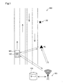
図1に示すように、本実施形態の位置推定システム500は、位置推定装置100と、送信機ALと、基地局BSと、を備える。本実施形態では、位置推定装置100は、車両MCに搭載されている。なお、位置推定装置100は、例えば、船舶やドローンなどの車両以外の物体に搭載されていてもよい。また、位置推定システム500は、基地局BSを備えなくてもよい。
A. First Embodiment As shown in FIG. 1, a
図2に示すように、車両MCは、位置推定装置100のほか、車両制御部110と、カメラ22と、GNSSセンサ24とを備える。車両制御部110は、車両MCの制御を行う機能部であり、車両制御部110には、カメラ22、GNSSセンサ24が電気的に接続されているため、これらのセンサによる検知結果が通知される。カメラ22は、車両の前方における周辺画像を取得する。GNSS(Global Navigation Satellite System)センサ24は、例えば、GPS(Global Positioning System)センサにより構成され、GPSを構成する人工衛星から受信する電波に基づき、現在位置を検出する。
As shown in FIG. 2, the vehicle MC includes a
本実施形態の位置推定装置100は、車両MCの車両制御部110と電気的に接続されている。具体的には、本実施形態の位置推定装置100は、車両MCのOBD2に接続されているため、位置推定装置100は、車両制御部110から車両MCの各種の情報の受信が可能である。なお、位置推定装置100と車両MCとの接続はこれに限られず、例えば、無線通信による接続を用いてもよい。また、位置推定装置100と車両MCとは接続されておらず、位置推定装置100が、カメラ22やGNSSセンサ24を別途備えてもよい。本実施形態では、OBD2から位置推定装置100へ電力が供給されるが、これに限られず、位置推定装置100は別途バッテリーを備えてもよく、車両MCのシガーソケットから位置推定装置100の電力を供給してもよい。
The
位置推定装置100は、画像取得部11と、抽出部12と、受信部13と、特定部14と、推定部15とを備える。位置推定装置100は、CPUと、ROMやRAMなどのメモリと、を備える周知のコンピュータとして構成されている。画像取得部11は、周辺環境の画像を取得する。本実施形態では、カメラ22により取得された画像を車両MCから取得する。抽出部12は、取得された画像からランドマークの情報を抽出する。ここで、ランドマークとは、SLAMに用いられ得る物体のことを言う。SLAMとは、Simultaneous Localization And Mappingの頭字語であり、自己位置推定と環境地図作成とを同時に行う手法のことである。ランドマークとしては、例えば、案内標識や、看板などが挙げられる。受信部13は、送信機ALからのランドマークの情報を受信する。特定部14は、受信したランドマークの情報と抽出したランドマークの情報とを照合することにより、ランドマークを特定する。推定部15は、ランドマークの情報を用いて現在位置を推定する。
The
送信機ALは、位置推定装置100へランドマークの情報を送信する機器である。本実施形態では、送信機ALは、信号機に設けられている。送信機ALは、所定の間隔を開けてランドマークの情報を発信する。
The transmitter AL is a device that transmits landmark information to the
基地局BSは、送信機ALと位置推定装置100と通信可能な基地局である。基地局BSは、サーバ135を備え、サーバ135は、送信機ALや位置推定装置100と通信した情報を収集するとともに、管理する。サーバ135により管理された情報は、車両向けテレマティクスサービスや路車協調サービスや車車協調サービスに用いられる。以下、本実施形態における位置推定装置100の現在位置推定処理について説明する。
The base station BS is a base station that can communicate with the transmitter AL and the
図3に示すように、まず、位置推定装置100の画像取得部11は、周辺環境の画像を取得する。本実施形態では、画像取得部11は、車両制御部110を介して、車両MCのカメラ22により取得された画像を取得する(工程S100)。
As shown in FIG. 3, first, the
画像を取得した後、位置推定装置100の抽出部12は、取得した画像からランドマークの情報を抽出する(工程S110)。図4に示される画像は、晴天の場合に取得された画像の例である。本実施形態において、位置推定装置100の抽出部12は、まず、画像の中からオブジェクトを認識する。本実施形態では、オブジェクトとしてランドマークを認識し、より具体的には、抽出部12は、図4の図面右側にある「Cレストラン」の看板をオブジェクトとして認識する。そして、抽出部12は、「Cレストラン」の看板をランドマークLMとして、ランドマークの情報を抽出する。ランドマークの情報の抽出方法について、図5を用いて説明する。
After acquiring the image, the
本実施形態では、任意のマッピング関数を用いて、ランドマークを示す画像を、画像よりもデータ情報の少ないテキストなどのデジタル情報に変換する。このようにすることにより、位置推定装置100が扱うデータ情報を少なくできるため、迅速に処理を行うことができる。本実施形態では、ランドマークの情報として、看板の情報をマッピング関数によってアルファベットに変換した情報を用いる。具体的には、抽出部12は、看板の外形形状を確定した後、内部を所定の形状に分割し、各分割領域の画像をマッピング関数によりアルファベットにそれぞれ変換することにより、「ABBDEDEZCE」とのアルファベットの情報を得る。晴天時のように視界が良好である場合、位置推定装置100の抽出部12は、通常、正しくランドマークの情報を抽出できる。
In the present embodiment, an image indicating a landmark is converted into digital information such as text having less data information than an image using an arbitrary mapping function. By doing so, the data information handled by the
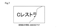
一方、ランドマークの情報を正しく抽出できない場合がある。例えば、図6に示される画像は、霧の場合に取得された画像の例である。このような場合、図7に示すように、画像の一部に不鮮明な部分が生じることがあり、この結果として、位置推定装置100の抽出部12は、画像からランドマークの情報を正しく抽出できない場合がある。具体的には、マッピング関数を用いた変換後において、正しく認識された場合の情報が、「ABBDEDEZCE」であるにもかかわらず、例えば、「ABBDBD??C?」というように変換されるような場合がある。
On the other hand, landmark information may not be correctly extracted. For example, the image shown in FIG. 6 is an example of an image acquired in the case of fog. In such a case, as shown in FIG. 7, an unclear portion may occur in a part of the image, and as a result, the
このような場合においても、本実施形態では、以下の処理が行われることにより、現在位置の推定が可能となる。具体的には、図3に示すように、位置推定装置100の受信部13は、送信機ALからランドマークの情報を受信する(工程S120)。本実施形態では、送信機ALが「Cレストラン」のマッピング関数を用いて変換した後の情報を示す「ABBDEDEZCE」との情報を発信した後、位置推定装置100の受信部がこの情報を受信する。送信機ALは、予め周囲のランドマークを特定する情報を記憶している。送信機ALは、これを繰り返し発信している。送信機ALが発信するランドマークを特定する情報は一つに限らず、2以上の場合もあり得る。
Even in such a case, in the present embodiment, the current processing can be estimated by performing the following processing. Specifically, as shown in FIG. 3, the receiving
その後、位置推定装置100の特定部14は、受信したランドマークの情報と、記抽出したランドマークの情報とを照合する(工程S140)。そして、照合ができた場合(S140:YES)、特定部14は、ランドマークを特定することができる。本実施形態では、照合ができた場合とは、抽出したランドマークの情報と受信したランドマークの情報とのうち、5割以上の情報が一致することをいう。送信機ALが複数のランドマークを特定する情報を発信していれば、特定部14は、これらの情報を順次照合に用いる。
After that, the
照合ができない場合(S140:NO)、受信したランドマークの情報と抽出したランドマークの情報とは一致しない情報であるため、ランドマークは特定できずにフローが終了する。 If the collation cannot be performed (S140: NO), the received landmark information and the extracted landmark information do not match, and thus the landmark cannot be identified and the flow ends.
一方、照合ができた場合(S140:YES)、特定部14はランドマークを特定し、特定したランドマークと、画像取得部11が取得した画像とを用いて、現在位置の推定を行う(工程S150)。具体的には、推定部15は、取得した画像の全体に対するランドマークの位置および大きさを用いて、現在位置の推定を行う。以上により、このフローは終了するが、この処理は、位置推定装置100の電源が投入されている限り、繰り返し行われる。
On the other hand, if the verification is successful (S140: YES), the specifying
通常、位置推定装置100は、車両MCのGNSSセンサ24から、位置推定装置100のおおよその位置を認識している。しかし、この処理を行うことにより、現在位置の推定精度が向上する。
Normally, the
そして、本実施形態によれば、天候などの影響によりランドマークを正しく観測できない場合においても、送信機ALから受信したランドマークの情報を用いることにより、現在位置の推定精度が向上する。 According to the present embodiment, even when a landmark cannot be correctly observed due to the influence of weather or the like, the estimation accuracy of the current position is improved by using the information of the landmark received from the transmitter AL.
また、本実施形態では、送信機ALが信号機に設けられている。このようにすることにより、既存の設備及び電源を用いて、ランドマークの情報を送信することができる。 In the present embodiment, the transmitter AL is provided in the traffic light. By doing so, landmark information can be transmitted using the existing equipment and power supply.
ここで、送信機ALが送信するランドマークの情報は、ランドマークの情報を送信する時刻の情報を含んでもよい。位置推定装置100の特定部14は、複数の送信機ALからの複数のランドマークの情報を受信した場合、受信したランドマークの情報の中で、最も新しい時刻の情報が含まれるランドマークの情報を用いて、ランドマークの特定を行ってもよい。図8に示すように、複数の送信機AL1,AL2が存在することにより、複数のランドマークの情報を受信する場合においても、最新情報を用いてランドマークの特定を行うため、現在位置の推定精度を向上できる。
Here, the landmark information transmitted by the transmitter AL may include information on the time at which the landmark information is transmitted. When receiving the information of a plurality of landmarks from the plurality of transmitters AL, the specifying
また、送信機ALが発信する情報として、さらに、周辺の交通情報を含んでもよい。このようにすることにより、位置推定装置100が受信した情報を車両MCの車両制御部110に通知することにより、車両MCの車両制御部110は、周囲の交通情報を反映した車両MCの制御が可能となる。
The information transmitted by the transmitter AL may further include traffic information of the surrounding area. By doing so, by notifying the information received by the
B.変形例
上述の実施形態では、送信機ALは信号機に設けられていたが、これに限定されない。送信機ALとして、例えば、街灯を用いてもよく、電光掲示板を用いてもよく、WiFiの通信装置を用いてもよい。また、送信機ALは、道路もしくは建物の中に埋め込まれていてもよい。このようにすることにより、送信機ALの設置場所の自由度を向上できる。また、送信機ALは、ドローンや車両などの移動体に設けられていてもよい。このようにすることにより、送信機ALのシステム整備時などに用いることができる。送信機ALを移動体に設ける場合は、移動体の移動位置に応じて情報を発信する対象となるランドマークを変更すればよい。
B. Modification In the above-described embodiment, the transmitter AL is provided in the traffic light. However, the present invention is not limited to this. As the transmitter AL, for example, a streetlight, an electric bulletin board, or a WiFi communication device may be used. Further, the transmitter AL may be embedded in a road or a building. By doing so, the degree of freedom of the installation location of the transmitter AL can be improved. Further, the transmitter AL may be provided on a moving body such as a drone or a vehicle. By doing so, it can be used when the system of the transmitter AL is maintained. When the transmitter AL is provided on a moving object, a landmark to which information is transmitted may be changed according to the moving position of the moving object.
本発明は、上述の実施形態や変形例に限られるものではなく、その趣旨を逸脱しない範囲において種々の構成で実現することができる。例えば、発明の概要の欄に記載した各形態中の技術的特徴に対応する本実施形態、変形例中の技術的特徴は、上述の課題の一部又は全部を解決するために、あるいは、上述の効果の一部又は全部を達成するために、適宜、差し替えや、組み合わせを行うことが可能である。また、その技術的特徴が本明細書中に必須なものとして説明されていなければ、適宜、削除することが可能である。 The present invention is not limited to the above-described embodiments and modified examples, and can be implemented with various configurations without departing from the spirit thereof. For example, the present embodiment corresponding to the technical features in each of the embodiments described in the summary of the invention, the technical features in the modifications may be used to solve some or all of the above-described problems, or In order to achieve some or all of the effects described above, replacements and combinations can be made as appropriate. If the technical features are not described as essential in this specification, they can be deleted as appropriate.
11 画像取得部、12 抽出部、13 受信部、14 特定部、15 推定部、22 カメラ、24 GNSSセンサ、100 位置推定装置、110 車両制御部、135 サーバ、500 位置推定システム、AL 送信機、BS 基地局、LM ランドマーク、MC 車両、 11 image acquisition section, 12 extraction section, 13 reception section, 14 identification section, 15 estimation section, 22 camera, 24 GNSS sensor, 100 position estimation device, 110 vehicle control section, 135 server, 500 position estimation system, AL transmitter, BS base station, LM landmark, MC vehicle,
Claims (5)
前記画像からランドマークの情報を抽出する抽出部(12)と、
前記ランドマークの情報を受信する受信部(13)と、
前記受信したランドマークの情報と、前記抽出したランドマークの情報とを照合することにより、前記ランドマークを特定する特定部(14)と、
前記特定したランドマークの情報と、前記画像とを用いて、現在位置を推定する推定部(15)と、を備える、位置推定装置(100)。 An image acquisition unit (11) for acquiring an image of the surrounding environment;
An extraction unit (12) for extracting landmark information from the image;
A receiving unit (13) for receiving the landmark information;
A specifying unit (14) for specifying the landmark by comparing the received landmark information with the extracted landmark information;
A position estimating device (100), comprising: an estimating unit (15) for estimating a current position using information of the specified landmark and the image.
前記前記位置推定装置へ前記ランドマークの情報を送信する送信機(AL)と、を備える位置推定システム(500)であって、
前記送信機が送信する前記ランドマークの情報は、前記ランドマークの情報を送信する時刻の情報を含み、
前記特定部は、複数の前記ランドマークの情報を受信した場合、受信した前記ランドマークの情報の中で、最も新しい時刻の情報が含まれる前記ランドマークの情報を用いて前記ランドマークの特定を行う、位置推定システム。 A position estimation device according to claim 1,
A transmitter (AL) for transmitting the information of the landmark to the position estimating device, wherein:
The landmark information transmitted by the transmitter includes information of a time at which the landmark information is transmitted,
When the information of the plurality of landmarks is received, the identification unit identifies the landmark by using information of the landmark including information of the latest time among the received information of the landmarks. Do, position estimation system.
前記送信機は、信号機に設けられている、位置推定システム。 The position estimation system according to claim 2,
The position estimation system, wherein the transmitter is provided in a traffic light.
前記送信機は、道路もしくは建物の中に埋め込まれている、位置推定システム。 The position estimation system according to claim 2,
The position estimation system, wherein the transmitter is embedded in a road or a building.
前記送信機は、ドローンもしくは車両に設けられている、位置推定システム。 The position estimation system according to claim 2,
The position estimation system, wherein the transmitter is provided in a drone or a vehicle.
Priority Applications (2)
| Application Number | Priority Date | Filing Date | Title |
|---|---|---|---|
| JP2018123161A JP2020003348A (en) | 2018-06-28 | 2018-06-28 | Position estimating device and position estimating system |
| US16/452,896 US11393221B2 (en) | 2018-06-28 | 2019-06-26 | Location estimation apparatus and location estimation system |
Applications Claiming Priority (1)
| Application Number | Priority Date | Filing Date | Title |
|---|---|---|---|
| JP2018123161A JP2020003348A (en) | 2018-06-28 | 2018-06-28 | Position estimating device and position estimating system |
Publications (1)
| Publication Number | Publication Date |
|---|---|
| JP2020003348A true JP2020003348A (en) | 2020-01-09 |
Family
ID=69054698
Family Applications (1)
| Application Number | Title | Priority Date | Filing Date |
|---|---|---|---|
| JP2018123161A Pending JP2020003348A (en) | 2018-06-28 | 2018-06-28 | Position estimating device and position estimating system |
Country Status (2)
| Country | Link |
|---|---|
| US (1) | US11393221B2 (en) |
| JP (1) | JP2020003348A (en) |
Citations (3)
| Publication number | Priority date | Publication date | Assignee | Title |
|---|---|---|---|---|
| JP2007093260A (en) * | 2005-09-27 | 2007-04-12 | Nissan Motor Co Ltd | Navigation apparatus, update system for map data stored in navigation apparatus, and map data update method |
| WO2015083538A1 (en) * | 2013-12-06 | 2015-06-11 | 日立オートモティブシステムズ株式会社 | Vehicle position estimation system, device, method, and camera device |
| JP2017073023A (en) * | 2015-10-08 | 2017-04-13 | 住友電気工業株式会社 | Traffic event information provision system, central device, unmanned flying body, and traffic event information provision program |
Family Cites Families (7)
| Publication number | Priority date | Publication date | Assignee | Title |
|---|---|---|---|---|
| JPH10122871A (en) | 1996-10-24 | 1998-05-15 | Sony Corp | Device and method for detecting state |
| JP3485774B2 (en) | 1997-11-07 | 2004-01-13 | 株式会社豊田中央研究所 | Traffic flow simulation system |
| JP2001283373A (en) | 2000-03-30 | 2001-10-12 | Toshiba Corp | Traffic flow measuring system |
| JP2012133726A (en) | 2010-12-24 | 2012-07-12 | Nissan Motor Co Ltd | Onboard communication device and communication method |
| KR20160002178A (en) | 2014-06-30 | 2016-01-07 | 현대자동차주식회사 | Apparatus and method for self-localization of vehicle |
| CN111351495A (en) | 2015-02-10 | 2020-06-30 | 御眼视觉技术有限公司 | Server system, method and machine-readable medium |
| WO2018017793A1 (en) * | 2016-07-21 | 2018-01-25 | Intelligent Technologies International, Inc. | System and method for creating, updating, and using maps generated by probe vehicles |
-
2018
- 2018-06-28 JP JP2018123161A patent/JP2020003348A/en active Pending
-
2019
- 2019-06-26 US US16/452,896 patent/US11393221B2/en active Active
Patent Citations (3)
| Publication number | Priority date | Publication date | Assignee | Title |
|---|---|---|---|---|
| JP2007093260A (en) * | 2005-09-27 | 2007-04-12 | Nissan Motor Co Ltd | Navigation apparatus, update system for map data stored in navigation apparatus, and map data update method |
| WO2015083538A1 (en) * | 2013-12-06 | 2015-06-11 | 日立オートモティブシステムズ株式会社 | Vehicle position estimation system, device, method, and camera device |
| JP2017073023A (en) * | 2015-10-08 | 2017-04-13 | 住友電気工業株式会社 | Traffic event information provision system, central device, unmanned flying body, and traffic event information provision program |
Also Published As
| Publication number | Publication date |
|---|---|
| US11393221B2 (en) | 2022-07-19 |
| US20200005057A1 (en) | 2020-01-02 |
Similar Documents
| Publication | Publication Date | Title |
|---|---|---|
| US9651393B2 (en) | Driving support device, driving support method, and recording medium storing driving support program | |
| US10762128B2 (en) | Information collection system and information center | |
| US10753757B2 (en) | Information processing apparatus and information processing method | |
| CN107209988B (en) | Method for determining the optimal speed of a motor vehicle approaching a traffic light | |
| WO2015083538A1 (en) | Vehicle position estimation system, device, method, and camera device | |
| CN110208739A (en) | Assist method, apparatus, equipment and the computer readable storage medium of vehicle location | |
| US20200322571A1 (en) | Imaging apparatus, image processing apparatus, and image processing method | |
| US10917808B2 (en) | Extra-vehicular communication device, onboard device, onboard communication system, communication control method, and communication control program | |
| US20200370890A1 (en) | Systems and methods for increasing the accuracy of vehicle positioning | |
| US11453367B2 (en) | Information processing system, program, and information processing method | |
| US11823464B2 (en) | Message-based image processing method and electronic device implementing same | |
| US11035927B2 (en) | Apparatus and method for determining a geographical position of a vehicle | |
| CN111886612A (en) | Mobile micropositioning | |
| JP2022030770A5 (en) | ||
| US20230392943A1 (en) | Server apparatus and information processing method | |
| US11710408B2 (en) | Communication apparatus, vehicle, computer-readable storage medium, and communication method | |
| US20190371178A1 (en) | Object detection device for vehicle and object detection system for vehicle | |
| JP2020003348A (en) | Position estimating device and position estimating system | |
| US20210223409A1 (en) | Method and device for determining a position of a vehicle | |
| US20200252544A1 (en) | Camera, method, non-transitory computer-readable medium, and system | |
| CN109579864B (en) | Navigation method and device | |
| JP7415849B2 (en) | Programs for vehicle systems and object signs | |
| KR20060098156A (en) | Position recognizing device and method for the position of mobile | |
| JP2019168985A (en) | Control device, control method, program and storage medium | |
| US20220225071A1 (en) | Base station, traffic communication system, and traffic communication method |
Legal Events
| Date | Code | Title | Description |
|---|---|---|---|
| A621 | Written request for application examination |
Free format text: JAPANESE INTERMEDIATE CODE: A621 Effective date: 20210215 |
|
| A131 | Notification of reasons for refusal |
Free format text: JAPANESE INTERMEDIATE CODE: A131 Effective date: 20211221 |
|
| A521 | Request for written amendment filed |
Free format text: JAPANESE INTERMEDIATE CODE: A523 Effective date: 20220217 |
|
| A02 | Decision of refusal |
Free format text: JAPANESE INTERMEDIATE CODE: A02 Effective date: 20220705 |