JP2020003030A - Member for forming open hole to wall - Google Patents

Member for forming open hole to wall Download PDF

Info

Publication number
JP2020003030A
JP2020003030A JP2018124332A JP2018124332A JP2020003030A JP 2020003030 A JP2020003030 A JP 2020003030A JP 2018124332 A JP2018124332 A JP 2018124332A JP 2018124332 A JP2018124332 A JP 2018124332A JP 2020003030 A JP2020003030 A JP 2020003030A
Authority
JP
Japan
Prior art keywords
wall
hole
hole forming
pipes
view
Prior art date
Legal status (The legal status is an assumption and is not a legal conclusion. Google has not performed a legal analysis and makes no representation as to the accuracy of the status listed.)
Granted
Application number
JP2018124332A
Other languages
Japanese (ja)
Other versions
JP6768035B2 (en
Inventor
有 水野
Yu Mizuno
有 水野
Current Assignee (The listed assignees may be inaccurate. Google has not performed a legal analysis and makes no representation or warranty as to the accuracy of the list.)
Inaba Denki Sangyo Co Ltd
Original Assignee
Inaba Denki Sangyo Co Ltd
Priority date (The priority date is an assumption and is not a legal conclusion. Google has not performed a legal analysis and makes no representation as to the accuracy of the date listed.)
Filing date
Publication date
Application filed by Inaba Denki Sangyo Co Ltd filed Critical Inaba Denki Sangyo Co Ltd
Priority to JP2018124332A priority Critical patent/JP6768035B2/en
Publication of JP2020003030A publication Critical patent/JP2020003030A/en
Application granted granted Critical
Publication of JP6768035B2 publication Critical patent/JP6768035B2/en
Active legal-status Critical Current
Anticipated expiration legal-status Critical

Links

Images

Landscapes

  • Building Environments (AREA)
  • Supports For Pipes And Cables (AREA)

Abstract

To provide a member for forming an open hole to a wall, capable of installing pipes even in a case where a wall is not formed.SOLUTION: A member for forming an open hole to a wall comprises: insertion parts 11, 11 configured in a cylindrical shape that allows pipes 8 to be inserted, and capable of inserting fastening members 10, 10 fixed to a ceiling or floor F; and a plurality of reinforcement ribs provided on an inner surface, and configured by combining a plurality of members 1, 2 divided into at least two in a radial direction of the cylindrical shape. The plurality of ribs is formed along the axial direction of the cylindrical shape.SELECTED DRAWING: Figure 10

Description

本発明は、壁への貫通孔形成部材に関する。   The present invention relates to a member for forming a through hole in a wall.

従来、躯体に配管類を通すためには、まず、躯体に貫通孔を形成し、形成された貫通孔に配管類を挿通させる。挿通した配管類の貫通孔から外れた部分にシート状の熱膨張耐熱シール材を巻き付けた後、前記熱膨張耐熱シール材の外側に備える粘着テープにより前記巻き付けた状態を保持する。この状態から、前記熱膨張耐熱シール材が貫通孔内に位置するように配管類を移動させる。そののち、移動した前記熱膨張耐熱シール材を張り付けた外側の粘着テープの外周面と貫通孔の内周面との間にモルタルや耐火パテ等の耐火性充填材を充填する(例えば特許文献1)。   Conventionally, in order to pass pipes through a frame, first, a through hole is formed in the frame, and the pipes are inserted through the formed through hole. After the sheet-like heat-expanding heat-resistant seal material is wound around the portion of the pipes that have passed through the through-holes, the wound state is held by an adhesive tape provided outside the heat-expansion heat-resistant seal material. From this state, the piping is moved so that the heat-expandable heat-resistant seal material is located in the through hole. After that, a refractory filler such as mortar or refractory putty is filled between the outer peripheral surface of the outer pressure-sensitive adhesive tape to which the moved heat-expandable heat-resistant sealing material is attached and the inner peripheral surface of the through hole (for example, Patent Document 1). ).

特開2000−240854号公報JP 2000-240854 A

上記特許文献1では、躯体が床であるが、壁に配管類を通す場合も同様である。つまり、壁に配管類を通す場合には、床と同様に壁に予め貫通孔が形成されている場合にのみ配管類を通すことができる構成であるため、壁が形成されていない場合には、壁を形成する前に、配管類を設置することができない不都合があり、改善の余地があった。   In Patent Literature 1, the skeleton is a floor, but the same applies when piping is passed through a wall. In other words, when pipes are passed through the wall, the pipes can be passed only when the through-holes are formed in advance in the wall, like the floor. However, there is a disadvantage that the pipes cannot be installed before the wall is formed, and there is room for improvement.

本発明は前述の状況に鑑み、解決しようとするところは、壁が形成されていない場合でも、配管類を施工することができる壁への貫通孔形成部材を提供するものである。   SUMMARY OF THE INVENTION The present invention has been made in view of the above circumstances, and has as its object to provide a member for forming a through hole in a wall on which piping can be constructed even when a wall is not formed.

本発明の壁への貫通孔形成部材は、前述の課題解決のために、配管類を挿通可能な筒形状に構成され、かつ、天井又は床に固定する締結部材を挿通可能な挿通部を備えたことを特徴としている。   In order to solve the above-mentioned problems, the through-hole forming member for the wall of the present invention is configured in a tubular shape through which piping can be inserted, and includes an insertion portion through which a fastening member for fixing to a ceiling or a floor can be inserted. It is characterized by having.

本発明によれば、壁を形成する前に、床又は天井の壁が形成される位置に貫通孔形成部材を締結部材を用いて固定しておけば、固定した貫通孔形成部材に配管類を通すための貫通孔が形成されるので、壁が形成されていない場合であっても、壁を形成する前に、配管類を貫通孔形成部材に配置することができる。   According to the present invention, before forming a wall, if a through-hole forming member is fixed to a position where a wall of a floor or a ceiling is formed using a fastening member, piping is fixed to the fixed through-hole forming member. Since the through-hole for passing is formed, even if the wall is not formed, the pipes can be arranged on the through-hole forming member before the wall is formed.

又、本発明の壁への貫通孔形成部材は、筒形状の径方向に少なくとも2つに分割された複数の部材を組み合わせて構成されていることが好ましい。   Further, the member for forming a through-hole in the wall of the present invention is preferably constituted by combining a plurality of members divided into at least two in a radial direction of a cylindrical shape.

上記のように、壁を形成する前に固定された貫通孔形成部材に配管類を配置する場合に、少なくとも1つの部材を天井又は床に固定し、該固定した部材に配管類を配置した状態で他の部材を一体化して貫通孔形成部材を組み立てることで迅速に配管類を貫通孔形成部材に配置することができる。   As described above, when arranging the pipes on the through-hole forming member fixed before forming the wall, at least one member is fixed on the ceiling or the floor, and the pipes are arranged on the fixed member. By assembling the through-hole forming member by integrating other members, piping can be quickly arranged on the through-hole forming member.

又、本発明の壁への貫通孔形成部材は、内面に複数の補強用のリブを備え、該複数のリブが前記筒形状の軸方向に沿って形成されていてもよい。   The member for forming a through hole in a wall according to the present invention may have a plurality of reinforcing ribs on an inner surface thereof, and the plurality of ribs may be formed along an axial direction of the cylindrical shape.

上記のように、複数のリブが筒形状の軸方向に沿って形成されていれば、リブが配管類の挿通方向に沿って形成されることになるため、貫通孔形成部材内を移動させる配管類との接触抵抗を低減することができる。   As described above, if the plurality of ribs are formed along the axial direction of the cylindrical shape, the ribs are formed along the direction in which the pipes are inserted, so that the pipe that moves in the through-hole forming member is formed. The contact resistance with the kind can be reduced.

又、本発明の壁への貫通孔形成部材は、前記筒形状の軸方向両端部のうちの少なくとも一方の端部に、該端部から外部へ煙が放出されることを阻止する煙阻止部材を備えていてもよい。   The member for forming a through-hole in a wall according to the present invention may further include a smoke-suppressing member for preventing at least one of the two axial ends of the cylindrical shape from discharging smoke from the end to the outside. May be provided.

上記のように、筒形状の軸方向両端部のうちの少なくとも一方の端部に、煙阻止部材を備えていれば、火災時に発生する煙が他方の端部から内部へ移動して該一方の端部から外部に放出されることを阻止することができる。   As described above, if at least one end of the cylindrical axial ends is provided with a smoke blocking member, the smoke generated during a fire moves from the other end to the inside, and It can be prevented from being released from the end to the outside.

本発明によれば、配管類を挿通可能な筒形状に構成され、かつ、天井又は床に固定する締結部材を挿通可能な挿通部を備えることによって、壁が形成されていない場合でも、配管類を施工することができる壁への貫通孔形成部材を提供することができる。   According to the present invention, even when no wall is formed, the pipes are configured in a tubular shape through which the pipes can be inserted, and by providing an insertion portion through which a fastening member fixed to a ceiling or a floor can be inserted. Can be provided.

貫通孔形成部材の下側部材の正面図である。It is a front view of the lower member of a through-hole formation member. 同下側部材の平面図である。It is a top view of the same lower member. 同下側部材の底面図である。It is a bottom view of the same lower member. 同下側部材の左側面図である。It is a left view of the same lower member. 同下側部材の右側面図である。It is a right view of the same lower member. 図2におけるVI−VI線断面図である。FIG. 6 is a sectional view taken along line VI-VI in FIG. 2. 図2におけるVII−VII線断面図である。FIG. 7 is a sectional view taken along line VII-VII in FIG. 2. 図2におけるVIII−VIII線断面図である。FIG. 7 is a sectional view taken along line VIII-VIII in FIG. 2. (a),(b)同下側部材を床にビスにより固定する直前の状態を示す縦断正面図及び縦断側面図である。(A), (b) It is the longitudinal front view and longitudinal side view which show the state just before fixing the lower member to the floor with a screw. (a),(b)は床に固定された同下側部材に配管類を配置して上側部材を被せた状態を示す縦断正面図及び縦断側面図である。(A), (b) is the longitudinal front view and longitudinal side view which show the state which arrange | positioned piping and the upper member over the same lower member fixed to the floor. (a),(b)は図10の状態から壁を装着した状態を示す縦断正面図及び縦断側面図である。(A), (b) is the longitudinal front view and longitudinal side view which show the state which mounted | wore the wall from the state of FIG. (a)は煙阻止部材を構成する2つの部材を示す正面図、(b)は煙阻止部材を構成する2つの部材のうちの一方の部材を内側から見た図である。(A) is a front view showing the two members constituting the smoke blocking member, and (b) is a view of one of the two members constituting the smoke blocking member viewed from the inside. 煙阻止部材を貫通孔形成部材の長手方向両端に取り付けた縦断側面図である。It is a vertical side view which attached the smoke prevention member to the longitudinal direction both ends of the through-hole formation member. 他の形態の貫通孔形成部材を示し、(a)は、それの平面図、(b)は2つの貫通孔形成部材を上下方向から一体する直前の状態を示す正面図である。FIG. 7A is a plan view of another form of the through-hole forming member, and FIG. 7B is a front view showing a state immediately before the two through-hole forming members are integrated from above and below. 他の形態の貫通孔形成部材の4個を連結部材により連結する直前の状態を示す正面図である。It is a front view showing the state immediately before connecting four of the penetration hole formation members of other forms with a connection member. 他の形態の貫通孔形成部材の2個を連結する直前の状態を示す平面図である。It is a top view showing the state immediately before connecting two of the penetration hole formation members of other forms. 他の形態の貫通孔形成部材の2個を連結する直前の状態を示す平面図である。It is a top view showing the state immediately before connecting two of the penetration hole formation members of other forms. 他の形態の貫通孔形成部材を示し、(a)は、それの平面図、(b)はそれの正面図、(c)は、それの側面図である。9A and 9B show another form of a through-hole forming member, wherein FIG. 9A is a plan view thereof, FIG. 9B is a front view thereof, and FIG. 9C is a side view thereof. 他の形態の貫通孔形成部材を示し、(a)は、それの正面図、(b)は、それの側面図、(c)は、それの底面図である。FIGS. 4A and 4B show another form of a through-hole forming member, wherein FIG. 4A is a front view thereof, FIG. 4B is a side view thereof, and FIG. 4C is a bottom view thereof. 他の形態の貫通孔形成部材を示し、(a)は、それの平面図、(b)はそれの正面図、(c)は、それの側面図である。9A and 9B show another form of a through-hole forming member, wherein FIG. 9A is a plan view thereof, FIG. 9B is a front view thereof, and FIG. 9C is a side view thereof. 他の形態の貫通孔形成部材を示し、(a)は、それの平面図、(b)はそれの正面図、(c)は、それの縦断側面図である。7A and 7B show another form of a through-hole forming member, in which FIG. 7A is a plan view thereof, FIG. 7B is a front view thereof, and FIG.

以下、本発明の実施形態を図面に基づいて説明する。   Hereinafter, embodiments of the present invention will be described with reference to the drawings.

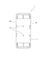
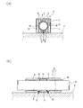
本発明の壁への貫通孔形成部材について説明する。貫通孔形成部材は、上側に位置する上側部材と上側部材と同一構成の下側に位置する下側部材とから構成されているが、異なる構成にしてもよい。図1〜図8には、一方の下側部材1を示し、この下側部材1を長手方向の軸回りで180度回転させることにより、上側部材2(図10(a),(b)参照)を構成することができる。ここでは、下側部材1と上側部材2とを同一部材から構成することによって、上下方向を気にすることなく、固定することができるようになっているが、異なる形状から構成してもよい。下側部材1は、底壁部3と底壁部3の幅方向両端から上方に延びる左右の側壁部4A,4Bとを備えている。ここでは、上側部材2及び下側部材1を合成樹脂から形成しているが、金属等で構成してもよく、材料は限定されない。   The member for forming a through hole in a wall according to the present invention will be described. The through-hole forming member includes an upper member located on the upper side and a lower member located on the lower side of the same configuration as the upper member, but may have a different configuration. 1 to 8 show one lower member 1, and by rotating the lower member 1 by 180 degrees around the longitudinal axis, the upper member 2 (see FIGS. 10A and 10B). ) Can be configured. Here, the lower member 1 and the upper member 2 are configured from the same member, so that the lower member 1 and the upper member 2 can be fixed without worrying about the vertical direction, but may be configured from different shapes. . The lower member 1 includes a bottom wall portion 3 and left and right side wall portions 4A and 4B extending upward from both ends in the width direction of the bottom wall portion 3. Here, the upper member 2 and the lower member 1 are formed of a synthetic resin, but may be made of metal or the like, and the material is not limited.

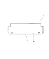
底壁部3は、平坦な底面を有し、長手方向両端のそれぞれに外側ほど径が大きくなるテーパー部5を備えている。また、底壁部3は、長手方向略中央部に図9(b)に示す耐火材6を収容する平面視略矩形状(図2では幅方向に長い平面視略長方形状)の収容空間を形成する凹部7が形成され、凹部7の長手方向両端のそれぞれからテーパー部5,5にそれぞれ向かって配管類8を支持する複数(図では5本)の補強用のリブ9が形成されている。これらリブ9は、図2に示すように、長手方向(筒形状の軸方向)に沿って形成され、しかも断面形状が円形の配管類8を確実に支持できるように幅方向外側に位置するリブ9ほど高さが高くなっている(図7及び図8参照)。また、凹部7を挟んで両側に位置する10本のリブ9のうちの幅方向中央に位置するリブ9,9それぞれの長手方向中央側端部に、床(又は天井)Fに下側部材1を固定するためのビス(締結部材)10(図9(a)参照)を挿通可能な2つの貫通孔(挿通部)11,11を備えている。複数のリブ9が筒形状の軸方向に沿って形成されていれば、リブ9が配管類8の挿通方向に沿って形成されることになるため、貫通孔形成部材H内を移動させる配管類8との接触抵抗を低減することができる。配管類8としては、給湯管、給水管、排水管、電線管等が挙げられる。ここでは、締結部材としてビス10を示しているが、床又は天井に備えた孔に差し込んで固定するピンや床又は天井に取り付けた固定部に貫通孔形成部材Hを締め付け固定するバンドであってもよい。   The bottom wall portion 3 has a flat bottom surface, and is provided with a tapered portion 5 having a diameter that increases toward the outside at both ends in the longitudinal direction. The bottom wall 3 has a substantially rectangular accommodation space (in FIG. 2, a substantially rectangular shape that is long in the width direction in plan view) that accommodates the refractory material 6 shown in FIG. A concave portion 7 to be formed is formed, and a plurality (five in the figure) of reinforcing ribs 9 that support the pipes 8 from both ends in the longitudinal direction of the concave portion 7 toward the tapered portions 5 and 5 are formed. . As shown in FIG. 2, the ribs 9 are formed along the longitudinal direction (axial direction of the cylindrical shape), and are located on the outside in the width direction so as to reliably support the pipes 8 having a circular cross section. The height is increased by about 9 (see FIGS. 7 and 8). The lower member 1 is attached to the floor (or ceiling) F at the longitudinal center ends of the ribs 9 located at the center in the width direction of the ten ribs 9 located on both sides of the recess 7. 9 (see FIG. 9 (a)) for fixing screws (fastening members) 10 are provided. If the plurality of ribs 9 are formed along the axial direction of the cylindrical shape, the ribs 9 will be formed along the direction in which the pipes 8 are inserted. 8 can be reduced. Examples of the pipes 8 include a hot water supply pipe, a water supply pipe, a drain pipe, and a conduit pipe. Here, the screw 10 is shown as a fastening member, but it is a pin that is inserted into a hole provided in the floor or ceiling and is a band that fastens and fixes the through-hole forming member H to a fixing portion attached to the floor or ceiling. Is also good.

耐火材6としては、熱膨張性の耐火材を用いている。この熱膨張性の耐火材は、熱膨張性(加熱により体積が増加する性質)と耐火性(熱に耐えやすい性質、溶融温度が高く燃えにくい性質)とを有する部材である。熱膨張性の耐火材としては、公知の材質のものを特に制限なく用いることができ、例えばパテ状部材(熱膨張性パテ状耐火材)を用いることができる。熱膨張性の耐火材は、例えば所定温度(例えば200℃)以上に加熱された際に、その厚み方向に膨張して配管類8と貫通孔形成部材Hの貫通孔19(図10(b)参照)との間の隙間を埋めることで壁を挟んで一方の部屋から他方の部屋へ貫通孔形成部材H内を通して火炎が移動することを防止する。   As the refractory material 6, a thermally expandable refractory material is used. The heat-expandable refractory material is a member having heat expansion properties (the property of increasing the volume by heating) and fire resistance (the property of easily withstanding heat, the property of a high melting temperature and the difficulty of burning). As the heat-expandable refractory material, a known material can be used without any particular limitation. For example, a putty-like member (heat-expandable putty-like refractory material) can be used. For example, when heated to a predetermined temperature (for example, 200 ° C.) or more, the heat-expandable refractory material expands in its thickness direction and expands in the piping 8 and the through-hole 19 of the through-hole forming member H (FIG. 10B). (See FIG. 1) to prevent the flame from moving through the through-hole forming member H from one room to the other room across the wall.

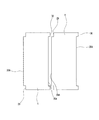
左右の側壁部4A,4Bについて説明すれば、図2及び図7に示すように、一方(左側)の側壁部4Aに対して他方(右側)の側壁部4Bが高くなっている。また、高くなっている右側の側壁部4Bの長手方向両端部のそれぞれに、長手方向に長い平面視長方形状の空間12が形成されるように右側の側壁部4Bの内面に3面を有する囲い部13を備えている。これに対して、低くなっている左側の側壁部4Aの長手方向両端部のそれぞれに、前記空間12に入り込み可能な平面視長方形状の板部14を備えている。また、右側の側壁部4Bの中央部の2箇所(前記凹部7の長手方向両端それぞれの近傍箇所)に内側に突出する第1係止部15を備えている。また、前記第1係止部15に上下方向から係止可能となるように外側に突出する第2係止部16を、左側の側壁部4Aの中央部の2箇所(前記凹部7の長手方向両端それぞれの近傍箇所)に備えている。したがって、下側部材1に上側部材2を上方から合わせることによって、上側部材2の2枚の板部14,14が下側部材1の2つの空間12,12にそれぞれ入り込んで、上側部材2と下側部材1とが位置決めされる。位置決めされると同時に、上側部材2の4つの係止部15,15,16,16のそれぞれが下側部材1の4つの係止部16,16,15,15のそれぞれに係止して、上側部材2と下側部材1とが分離不能に係止固定される。   Describing the left and right side walls 4A and 4B, as shown in FIGS. 2 and 7, one (left) side wall 4A is higher than the other (right) side wall 4B. In addition, an enclosure having three surfaces on the inner surface of the right side wall portion 4B such that a rectangular space 12 which is long in the longitudinal direction and which is rectangular in a plan view is formed at each of both end portions in the longitudinal direction of the right side wall portion 4B which is raised. A section 13 is provided. On the other hand, each of the lower end portions of the left side wall portion 4 </ b> A is provided with a rectangular plate portion 14 in a plan view that can enter the space 12 at each of both ends in the longitudinal direction. Further, first locking portions 15 protruding inward are provided at two places in the center of the right side wall 4B (near each of both ends in the longitudinal direction of the recess 7). Further, the second locking portion 16 protruding outward so as to be able to lock to the first locking portion 15 from above and below is provided at two places at the center of the left side wall 4A (in the longitudinal direction of the recess 7). Near each end). Therefore, by fitting the upper member 2 to the lower member 1 from above, the two plate portions 14, 14 of the upper member 2 enter the two spaces 12, 12 of the lower member 1, respectively. The lower member 1 is positioned. At the same time as being positioned, each of the four locking portions 15, 15, 16, 16 of the upper member 2 is locked to each of the four locking portions 16, 16, 15, 15, 15 of the lower member 1, The upper member 2 and the lower member 1 are locked and fixed inseparably.

前記のように構成された貫通孔形成部材Hにより配管類8を配置する作業工程について説明する。   An operation process of disposing the pipes 8 by the through hole forming member H configured as described above will be described.

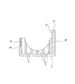
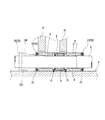
図9(a),(b)に示すように、床Fに下側部材1を配置して2個のビス10,10を用いて固定する。この固定する際に、床Fに下側部材1を固定する位置、つまり後述する壁17が設けられる位置がマーカーやテープ等により予め記されていて、その壁17の位置に合わせて下側部材1を固定することになる。下側部材1の固定が完了すると、配管類8を下側部材1に配置(載置)した後、上側部材2を上方から被せて下側部材1に上側部材2を係止固定する(図10(a),(b)参照)。この状態から、一対の壁17,17を設置する(図11(a),(b)参照)。なお、壁17,17の設置後は、壁17,17と貫通孔形成部材Hとの間に発生する隙間18にパテやモルタル等の充填材(図示せず)により塞ぐことになる。   As shown in FIGS. 9A and 9B, the lower member 1 is arranged on the floor F and fixed using two screws 10. When this is fixed, the position where the lower member 1 is fixed to the floor F, that is, the position where the wall 17 described later is provided is previously marked by a marker or tape, and the lower member 1 is adjusted in accordance with the position of the wall 17. 1 will be fixed. When the fixing of the lower member 1 is completed, the pipes 8 are arranged (placed) on the lower member 1, and then the upper member 2 is covered from above and the upper member 2 is locked and fixed to the lower member 1 (FIG. 10 (a), (b)). From this state, the pair of walls 17, 17 is installed (see FIGS. 11A and 11B). After the installation of the walls 17, 17, the gap 18 generated between the walls 17, 17 and the through-hole forming member H is closed with a filler (not shown) such as putty or mortar.

前記のように、壁17を形成する前に、床F(又は天井でもよい)の壁17が形成される位置に貫通孔形成部材Hを固定しておけば、固定した貫通孔形成部材Hに配管類8を挿通可能な筒形状(ここでは円筒形状)の貫通孔19(図10(b)参照)が形成されるので、壁17が形成されていない場合であっても、配管類8を固定した貫通孔形成部材Hに挿通して配置することができる。ここでは、床F(又は天井)への下側部材(一方の部材)1の固定で約半周分の貫通孔が形成される。   As described above, if the through-hole forming member H is fixed at a position where the wall 17 of the floor F (or may be a ceiling) is formed before the wall 17 is formed, the fixed through-hole forming member H can be fixed. Since the cylindrical (here, cylindrical) through hole 19 (see FIG. 10B) through which the pipes 8 can be inserted is formed, even if the wall 17 is not formed, the pipes 8 can be removed. It can be inserted through the fixed through-hole forming member H and arranged. Here, a through-hole for about a half circumference is formed by fixing the lower member (one member) 1 to the floor F (or ceiling).

また、壁17を形成する前に固定された貫通孔形成部材Hに配管類8を配置する場合に、2つに分割された一方の下側部材1に配管類8を配置した状態で他方の上側部材2を一体化することで迅速に配管類8を貫通孔形成部材Hに配置することができる。   When the pipes 8 are arranged on the through hole forming member H fixed before forming the wall 17, the pipes 8 are arranged on one lower member 1 divided into two while the other is arranged. By integrating the upper member 2, the pipes 8 can be quickly arranged on the through hole forming member H.

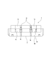
図12及び図13に示すように、前記構成の貫通孔形成部材Hの筒形状の軸方向両端部のそれぞれに、端部から外部へ煙が放出されることを阻止する煙阻止部材20を備えていてもよい。ここでは、煙阻止部材20を貫通孔形成部材Hの長手方向両端部に備えているが、一方の端部にのみ煙阻止部材20を備えて実施してもよい。   As shown in FIGS. 12 and 13, a smoke blocking member 20 is provided at each of the cylindrical axial ends of the through hole forming member H having the above-described configuration to prevent smoke from being released from the end to the outside. May be. Here, the smoke prevention member 20 is provided at both ends in the longitudinal direction of the through-hole forming member H. However, the smoke prevention member 20 may be provided at only one end.

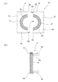
煙阻止部材20は、左右一対の部材21,21を係止固定することにより一体化して構成される。2つの部材21,21は、いずれも同一に構成されており、一方の部材21について説明する。部材21は、半リング状の合成ゴム発泡シート22と、この合成ゴム発泡シート22を保持する合成樹脂製(金属であってもよい)の枠部23とを備えている。枠部23は、合成ゴム発泡シート22を保持する円弧状の凹部23aが形成された本体部23Aと、一方の部材21と他方の部材21とを左右方向で合わせた時に他方の部材21に形成されている被係止部(図示せず)に係止して両方の部材21,21を一体化するための第1係止部としての第1係止爪23Bと、煙阻止部材20を貫通孔形成部材Hの長手方向の端部に形成の被係止部(図示せず)に係止するための第2係止部としての第2係止爪23Cとを備えている。第1係止爪23Bは、本体部23Aの上下に位置する内側端23U,23Uのうちの一方に他方の本体部23A側へ突出するように形成されている。第2係止爪23Cは、各部材21の裏面の2つの角部に後方に突出するように形成されている(全部で4つ)。合成ゴム発泡シート22は、EPDMゴムを主成分とした発泡シール材であるが、他の材料から構成されていてもよい。   The smoke prevention member 20 is integrally formed by locking and fixing a pair of left and right members 21 and 21. The two members 21 and 21 have the same configuration, and one member 21 will be described. The member 21 includes a semi-ring shaped synthetic rubber foam sheet 22 and a synthetic resin (may be metal) frame 23 holding the synthetic rubber foam sheet 22. The frame portion 23 is formed on the other member 21 when one member 21 and the other member 21 are combined in the left-right direction with the main body portion 23A having the arc-shaped concave portion 23a for holding the synthetic rubber foam sheet 22. A first locking claw 23B as a first locking portion for locking both members 21 and 21 by being locked to a locked portion (not shown), and penetrates the smoke prevention member 20. A second locking claw 23C as a second locking portion for locking to a locked portion (not shown) formed at a longitudinal end of the hole forming member H is provided. The first locking claw 23B is formed at one of the inner ends 23U, 23U located above and below the main body 23A so as to protrude toward the other main body 23A. The second locking claws 23C are formed at two corners on the back surface of each member 21 so as to protrude rearward (four in total). The synthetic rubber foam sheet 22 is a foam sealing material containing EPDM rubber as a main component, but may be made of another material.

図13に、貫通孔形成部材Hの長手方向両端に煙阻止部材20が係止固定されている状態を示している。図13の2点鎖線で示す煙阻止部材20を矢印の方向に移動させることにより、4つの第2係止爪23C(図13では2つのみ図示している)が貫通孔形成部材Hの端部に形成している被係止部(図示せず)に係止して、煙阻止部材20を貫通孔形成部材Hの両端のそれぞれに固定することができる。貫通孔形成部材Hの筒形状の軸方向両端部のうちの少なくとも一方の端部に、煙阻止部材20を備えていれば、火災時に発生する煙が貫通孔形成部材Hの他方の端部から内部へ移動して一方の端部から外部に放出されることを阻止することができる。   FIG. 13 shows a state in which the smoke blocking members 20 are locked and fixed to both ends in the longitudinal direction of the through hole forming member H. By moving the smoke blocking member 20 indicated by the two-dot chain line in FIG. 13 in the direction of the arrow, the four second locking claws 23C (only two are shown in FIG. 13) are provided at the ends of the through hole forming member H. The smoke blocking member 20 can be fixed to each of both ends of the through hole forming member H by being locked to a locked portion (not shown) formed in the portion. At least one end of the cylindrical axial ends of the through-hole forming member H is provided with the smoke blocking member 20, so that the smoke generated at the time of a fire is discharged from the other end of the through-hole forming member H. It can be prevented from moving inside and being discharged from one end to the outside.

尚、本発明は、上記実施形態に限定されるものではなく、本発明の要旨を逸脱しない範囲で種々の変更が可能である。例えば、複数の貫通孔形成部材を上下方向又は左右方向あるいは上下方向及び左右方向の両方向に位置決めできる構成を備えて実施してもよい。   Note that the present invention is not limited to the above embodiment, and various changes can be made without departing from the gist of the present invention. For example, the present invention may be implemented with a configuration in which a plurality of through-hole forming members can be positioned vertically or horizontally, or both vertically and horizontally.

図14(a),(b)では、貫通孔形成部材Hの上面の長手方向中央部の左右幅方向両端部のそれぞれに上方に突出する係止爪24,24を備え、それら係止爪24,24に係止する被係止部である凹部25,25を貫通孔形成部材Hの下面の長手方向中央部の左右幅方向両端部に形成している。また、図15では、貫通孔形成部材Hの4つの角部それぞれに略L字状の切欠き部26を長手方向全域に渡って形成している。左右方向で隣り合うように平行に並べられる2つの貫通孔形成部材H,Hの対向する側端部の下端に形成された切欠き部26,26間に跨って連結する略C字状の第1連結部材27を設けている。また、左右方向に2列で上下方向に2段となる4つの貫通孔形成部材H,H,H,Hを配置し、上側に位置する2つの貫通孔形成部材H,Hと下側に位置する2つの貫通孔形成部材H,Hとを同時に連結する第2連結部材28を設けている。これら第1連結部材27及び第2連結部材28は、切欠き部26,26に対して水平方向から移動させて入り込ませることにより貫通孔形成部材H,H,H,Hを連結する。また、図16では、貫通孔形成部材Hの左右の側壁29,30のうちの一方の側壁30の長さ方向全域よりも少し短い領域に凹部30Aを形成し、この凹部30Aに入り込んで位置決めするための凸部29Aを他方の側壁29に形成している。また、図17では、貫通孔形成部材Hの左右の側壁31,32のうちの一方の側壁31の長さ方向中央部に凹部31Aを形成し、この凹部31Aに入り込む凸部32Aを他方の側壁32の長さ方向中央部に形成している。   14A and 14B, locking claws 24, 24 protruding upward are provided at both ends in the left-right width direction at the center in the longitudinal direction of the upper surface of the through-hole forming member H. , 24 are formed at both ends in the left-right width direction at the longitudinal center of the lower surface of the through-hole forming member H. In FIG. 15, a substantially L-shaped notch 26 is formed in each of the four corners of the through-hole forming member H over the entire area in the longitudinal direction. A substantially C-shaped second connecting member extending across the notch portions 26 formed at the lower ends of the opposed side ends of the two through-hole forming members H, which are arranged in parallel so as to be adjacent to each other in the left-right direction. One connecting member 27 is provided. In addition, four through-hole forming members H, H, H, H arranged in two rows in the left-right direction and two steps in the vertical direction are arranged, and the two through-hole forming members H, H positioned on the upper side and the lower side are positioned on the lower side. A second connecting member 28 is provided for simultaneously connecting the two through-hole forming members H, H to be formed. The first connecting member 27 and the second connecting member 28 connect the through-hole forming members H, H, H, H by moving from the horizontal direction and entering the notches 26, 26. In FIG. 16, a recess 30A is formed in a region slightly shorter than the entire length direction of one of the side walls 30 of the left and right side walls 29, 30 of the through-hole forming member H, and enters into the recess 30A for positioning. Projection 29A is formed on the other side wall 29. In FIG. 17, a concave portion 31A is formed in the longitudinal center of one of the left and right side walls 31, 32 of the through hole forming member H, and the convex portion 32A that enters the concave portion 31A is formed on the other side wall. 32 are formed at the center in the length direction.

前記実施形態では、下側部材1の底壁部3にビス10を挿通する貫通孔11,11を形成しているため、上側部材2を下側部材1に被せる前に下側部材1をビス10で床Fに固定しなければならない構成であるが、図18(a),(b),(c)に示すように、ビスを挿通する貫通孔33A,33Aを貫通孔形成部材Hの長手方向両端のそれぞれにおける左右幅方向両端から長手方向外側にそれぞれ延びる延出部33,33に形成している。なお、図18では、貫通孔形成部材Hを1つの部材から構成したが、複数の部材から構成することもできる。また、図19(a),(b),(c)では、貫通孔形成部材Hの幅方向の両側壁34,35のうちの一方の側壁34の下端部でかつ長手方向一端部に幅方向外側に延出される第1延出部36と他方の側壁35の下端部でかつ長手方向他端部に幅方向外側に延出される第2延出部37とを備え、それら延出部36,37のそれぞれに貫通孔36A,37Aを形成している。また、貫通孔形成部材Hの底面において2つの延出部36,37が存在しない2つの角部に幅方向に隣接配置される貫通孔形成部材Hの第1延出部36又は第2延出部37が入り込む切欠き部38,39が形成されている。また、図20(a),(b),(c)では、貫通孔形成部材Hの長手方向両端の左右幅方向中央でかつ下端にそれぞれ、長手方向外側に延びる延出部40を備え、それら延出部40,40のそれぞれに貫通孔40Aを形成している。また、図21(a),(b),(c)では、貫通孔形成部材Hの底壁部41に2つの貫通孔41A,41Aを形成し、貫通孔形成部材Hの天壁部42の底壁部41に形成した貫通孔41A,41Aの直上方位置に貫通孔41A,41Aよりも大径の大径貫通孔42A,42Aを形成している。このように形成することによって、配管類8を貫通孔形成部材Hに通していない状態において、大径貫通孔42A,42Aを通して下方の貫通孔41A,41Aへビスを通すことができる。なお、図18〜図21では、貫通孔形成部材Hを1つの部材から構成しているが、複数の部材を組み合わせて構成することもできる。   In the above embodiment, since the through-holes 11, 11 through which the screws 10 are inserted are formed in the bottom wall portion 3 of the lower member 1, the lower member 1 is screwed before the upper member 2 is put on the lower member 1. In FIG. 18 (a), (b) and (c), the through holes 33A, 33A into which the screws are inserted are formed in the longitudinal direction of the through hole forming member H. Extension portions 33, 33 extending from both ends in the width direction at both ends in the longitudinal direction to the outside in the longitudinal direction, respectively. In FIG. 18, the through-hole forming member H is formed of one member, but may be formed of a plurality of members. 19 (a), (b) and (c), the width direction is provided at the lower end of one of the side walls 34 and 35 of the through hole forming member H in the width direction and at one end in the longitudinal direction. A first extension 36 extending outward and a second extension 37 extending at the lower end of the other side wall 35 and the other end in the longitudinal direction outward in the width direction are provided. The through holes 36A and 37A are formed in each of the 37. In addition, the first extension portion 36 or the second extension portion of the through-hole forming member H disposed adjacent to the two corners where the two extension portions 36 and 37 do not exist on the bottom surface of the through-hole forming member H in the width direction. Notch portions 38 and 39 into which the portion 37 enters are formed. 20 (a), 20 (b) and 20 (c), the through hole forming member H is provided with extending portions 40 which extend outward in the longitudinal direction, respectively, at the center in the left and right width direction and at the lower end of both ends in the longitudinal direction. A through hole 40A is formed in each of the extending portions 40,40. 21A, 21B, and 21C, two through holes 41A, 41A are formed in the bottom wall 41 of the through hole forming member H, and the top wall 42 of the through hole forming member H is formed. Large-diameter through holes 42A, 42A having a diameter larger than the through holes 41A, 41A are formed immediately above the through holes 41A, 41A formed in the bottom wall portion 41. By forming in this manner, screws can be passed through the large diameter through holes 42A, 42A to the lower through holes 41A, 41A in a state where the pipes 8 are not passed through the through hole forming member H. In FIGS. 18 to 21, the through-hole forming member H is configured by one member, but may be configured by combining a plurality of members.

また、前記実施形態では、固定した貫通孔形成部材Hに配管類8を配置してから壁17を形成したが、固定した貫通孔形成部材Hに壁17を形成してから配管類8を貫通孔形成部材Hに挿通させて配置してもよい。   Further, in the above-described embodiment, the pipes 8 are arranged on the fixed through-hole forming member H and then the wall 17 is formed. However, after the wall 17 is formed on the fixed through-hole forming member H, the pipes 8 are penetrated. It may be arranged to be inserted through the hole forming member H.

また、前記実施形態では、貫通孔形成部材Hを2つの部材1,2から構成したが、1つの部材又は3つ以上の任意の個数の部材から構成してもよい。   Further, in the above-described embodiment, the through-hole forming member H is configured by two members 1 and 2, but may be configured by one member or an arbitrary number of three or more members.

1…下側部材、2…上側部材、3…底壁部、4A,4B…左右の側壁部、5…テーパー部、6…耐火材、7…凹部、8…配管類、9…リブ、10…ビス、11…貫通孔、12…空間、13…囲い部、14…板部、15…第1係止部、16…第2係止部、17…壁、18…隙間、19…貫通孔、20…煙阻止部材、21…部材、22…合成ゴム発泡シート、23…枠部、23A…本体部、23B…係止爪、23C…係止爪、23U…内側端、23a…凹部、24…係止爪、25…凹部、26…切欠き部、27…第1連結部材、28…第2連結部材、29,30…側壁、29A…凸部、30A…凹部、31,32…側壁、31A…凹部、32A…凸部、33…延出部、33A…貫通孔、34,35…側壁、36,37…延出部、36A,37A…貫通孔、38,39…切欠き部、40…延出部、40A…貫通孔、41…底壁部、41A…貫通孔、42…天壁部、42A…大径貫通孔、F…床、H…貫通孔形成部材   DESCRIPTION OF SYMBOLS 1 ... Lower member, 2 ... Upper member, 3 ... Bottom wall part, 4A, 4B ... Left and right side wall parts, 5 ... Tapered part, 6 ... Refractory material, 7 ... Recessed part, 8 ... Pipings, 9 ... Rib, 10 ... Screw, 11 ... Through hole, 12 ... Space, 13 ... Enclosure part, 14 ... Plate part, 15 ... First locking part, 16 ... Second locking part, 17 ... Wall, 18 ... Gap, 19 ... Through hole , 20: smoke blocking member, 21: member, 22: synthetic rubber foam sheet, 23: frame portion, 23A: body portion, 23B: locking claw, 23C: locking claw, 23U: inner end, 23a: concave portion, 24 ... locking claw, 25 ... concave portion, 26 ... notched portion, 27 ... first connecting member, 28 ... second connecting member, 29, 30 ... side wall, 29A ... convex portion, 30A ... concave portion, 31, 32 ... side wall, 31A: concave portion, 32A: convex portion, 33: extending portion, 33A: through hole, 34, 35: side wall, 36, 37 ... extending portion, 36A, 37A ... Through holes, 38, 39: Notch, 40: Extension, 40A: Through hole, 41: Bottom wall, 41A: Through hole, 42: Top wall, 42A: Large diameter through hole, F: Floor, H: Through-hole forming member

Claims (4)

配管類を挿通可能な筒形状に構成され、かつ、天井又は床に固定する締結部材を挿通可能な挿通部を備えたことを特徴とする壁への貫通孔形成部材。   A through-hole forming member for a wall, which is formed in a tubular shape through which pipes can be inserted, and has an insertion portion through which a fastening member fixed to a ceiling or a floor can be inserted. 筒形状の径方向に少なくとも2つに分割された複数の部材を組み合わせて構成されていることを特徴とする請求項1に記載の壁への貫通孔形成部材。   The member for forming a through hole in a wall according to claim 1, wherein the member is formed by combining a plurality of members divided into at least two in a radial direction of a cylindrical shape. 内面に複数の補強用のリブを備え、該複数のリブが前記筒形状の軸方向に沿って形成されていることを特徴とする請求項1又は2に記載の壁への貫通孔形成部材。   The member for forming a through hole in a wall according to claim 1 or 2, wherein a plurality of reinforcing ribs are provided on an inner surface, and the plurality of ribs are formed along an axial direction of the cylindrical shape. 前記筒形状の軸方向両端部のうちの少なくとも一方の端部に、該端部から外部へ煙が放出されることを阻止する煙阻止部材を備えていることを特徴とする請求項1〜3のうちのいずれか1項に記載の壁への貫通孔形成部材。   At least one of the two axial ends of the cylindrical shape is provided with a smoke prevention member for preventing the emission of smoke from the end to the outside. The member for forming a through hole to a wall according to any one of the above.
JP2018124332A 2018-06-29 2018-06-29 Through hole forming member to the wall Active JP6768035B2 (en)

Priority Applications (1)

Application Number Priority Date Filing Date Title
JP2018124332A JP6768035B2 (en) 2018-06-29 2018-06-29 Through hole forming member to the wall

Applications Claiming Priority (1)

Application Number Priority Date Filing Date Title
JP2018124332A JP6768035B2 (en) 2018-06-29 2018-06-29 Through hole forming member to the wall

Publications (2)

Publication Number Publication Date
JP2020003030A true JP2020003030A (en) 2020-01-09
JP6768035B2 JP6768035B2 (en) 2020-10-14

Family

ID=69099275

Family Applications (1)

Application Number Title Priority Date Filing Date
JP2018124332A Active JP6768035B2 (en) 2018-06-29 2018-06-29 Through hole forming member to the wall

Country Status (1)

Country Link
JP (1) JP6768035B2 (en)

Citations (5)

* Cited by examiner, † Cited by third party
Publication number Priority date Publication date Assignee Title
JPS5315521U (en) * 1976-07-21 1978-02-09
JPS57102776U (en) * 1980-12-16 1982-06-24
JPS619686U (en) * 1984-06-21 1986-01-21 日立電線株式会社 Airtight fireproof structure for pipe penetrations
JP2000240854A (en) * 1999-02-18 2000-09-08 Inaba Denki Sangyo Co Ltd Thermal expansion material for fire protection
JP2007218320A (en) * 2006-02-15 2007-08-30 Kasaku Kamata Pipe fixture

Patent Citations (5)

* Cited by examiner, † Cited by third party
Publication number Priority date Publication date Assignee Title
JPS5315521U (en) * 1976-07-21 1978-02-09
JPS57102776U (en) * 1980-12-16 1982-06-24
JPS619686U (en) * 1984-06-21 1986-01-21 日立電線株式会社 Airtight fireproof structure for pipe penetrations
JP2000240854A (en) * 1999-02-18 2000-09-08 Inaba Denki Sangyo Co Ltd Thermal expansion material for fire protection
JP2007218320A (en) * 2006-02-15 2007-08-30 Kasaku Kamata Pipe fixture

Also Published As

Publication number Publication date
JP6768035B2 (en) 2020-10-14

Similar Documents

Publication Publication Date Title
KR101687140B1 (en) Device for Mounting a Fire Resistance Filler within a Pipe
JP6664997B2 (en) Holding tool
JP2018008052A (en) Support tool
JP2015209933A (en) Fireproof treatment tool using fire compartment wall open hole, and fireproof treatment structure
JP2020003030A (en) Member for forming open hole to wall
JP6348320B2 (en) Refractory material and fire barrier wall structure
JP2020003029A (en) Method for installing pipes to wall
JP6466672B2 (en) Joinery
JP4942964B2 (en) Drainage piping structure
KR20180124620A (en) Fire-stopping Pipe Jacket
JP6799524B2 (en) Fireproof material and fireproof compartment wall structure
JP6983215B2 (en) Through hole forming member to the wall
JP6586364B2 (en) door
JP2008510943A (en) Fire protection structure for bulkhead installation structure
JP2009055697A (en) Fire-spread inhibitor structure in hollow wall
JP6405215B2 (en) Smoke exhaust window
KR20190068167A (en) Fixing device for fireproof filling element
JP2014098305A (en) Drain piping joint
JP2017225812A (en) Fireproof pack member
KR101938732B1 (en) Construction method for bus duct
JP6377384B2 (en) Joinery
JP7432230B2 (en) Construction methods for fire-resistant components and fire-resistant structures
KR102417492B1 (en) Piercing sleeve unit
KR102324834B1 (en) An apparatus for filling fire resistance within a pipe used fab process in semiconductor
JP6980878B1 (en) Gap closing unit

Legal Events

Date Code Title Description
A621 Written request for application examination

Free format text: JAPANESE INTERMEDIATE CODE: A621

Effective date: 20200407

A871 Explanation of circumstances concerning accelerated examination

Free format text: JAPANESE INTERMEDIATE CODE: A871

Effective date: 20200407

A975 Report on accelerated examination

Free format text: JAPANESE INTERMEDIATE CODE: A971005

Effective date: 20200601

A131 Notification of reasons for refusal

Free format text: JAPANESE INTERMEDIATE CODE: A131

Effective date: 20200605

A521 Request for written amendment filed

Free format text: JAPANESE INTERMEDIATE CODE: A523

Effective date: 20200702

TRDD Decision of grant or rejection written
A01 Written decision to grant a patent or to grant a registration (utility model)

Free format text: JAPANESE INTERMEDIATE CODE: A01

Effective date: 20200828

A61 First payment of annual fees (during grant procedure)

Free format text: JAPANESE INTERMEDIATE CODE: A61

Effective date: 20200918

R150 Certificate of patent or registration of utility model

Ref document number: 6768035

Country of ref document: JP

Free format text: JAPANESE INTERMEDIATE CODE: R150

R250 Receipt of annual fees

Free format text: JAPANESE INTERMEDIATE CODE: R250