JP2020002903A - Power generating system and its control device and control method - Google Patents
Power generating system and its control device and control method Download PDFInfo
- Publication number
- JP2020002903A JP2020002903A JP2018124770A JP2018124770A JP2020002903A JP 2020002903 A JP2020002903 A JP 2020002903A JP 2018124770 A JP2018124770 A JP 2018124770A JP 2018124770 A JP2018124770 A JP 2018124770A JP 2020002903 A JP2020002903 A JP 2020002903A
- Authority
- JP
- Japan
- Prior art keywords
- load capacity
- value
- upper limit
- power generation
- capacity value
- Prior art date
- Legal status (The legal status is an assumption and is not a legal conclusion. Google has not performed a legal analysis and makes no representation as to the accuracy of the status listed.)
- Granted
Links
Images


Classifications
-
- F—MECHANICAL ENGINEERING; LIGHTING; HEATING; WEAPONS; BLASTING
- F01—MACHINES OR ENGINES IN GENERAL; ENGINE PLANTS IN GENERAL; STEAM ENGINES
- F01D—NON-POSITIVE DISPLACEMENT MACHINES OR ENGINES, e.g. STEAM TURBINES
- F01D17/00—Regulating or controlling by varying flow
-
- F—MECHANICAL ENGINEERING; LIGHTING; HEATING; WEAPONS; BLASTING
- F01—MACHINES OR ENGINES IN GENERAL; ENGINE PLANTS IN GENERAL; STEAM ENGINES
- F01K—STEAM ENGINE PLANTS; STEAM ACCUMULATORS; ENGINE PLANTS NOT OTHERWISE PROVIDED FOR; ENGINES USING SPECIAL WORKING FLUIDS OR CYCLES
- F01K23/00—Plants characterised by more than one engine delivering power external to the plant, the engines being driven by different fluids
- F01K23/02—Plants characterised by more than one engine delivering power external to the plant, the engines being driven by different fluids the engine cycles being thermally coupled
- F01K23/06—Plants characterised by more than one engine delivering power external to the plant, the engines being driven by different fluids the engine cycles being thermally coupled combustion heat from one cycle heating the fluid in another cycle
- F01K23/10—Plants characterised by more than one engine delivering power external to the plant, the engines being driven by different fluids the engine cycles being thermally coupled combustion heat from one cycle heating the fluid in another cycle with exhaust fluid of one cycle heating the fluid in another cycle
-
- F—MECHANICAL ENGINEERING; LIGHTING; HEATING; WEAPONS; BLASTING
- F02—COMBUSTION ENGINES; HOT-GAS OR COMBUSTION-PRODUCT ENGINE PLANTS
- F02G—HOT GAS OR COMBUSTION-PRODUCT POSITIVE-DISPLACEMENT ENGINE PLANTS; USE OF WASTE HEAT OF COMBUSTION ENGINES; NOT OTHERWISE PROVIDED FOR
- F02G5/00—Profiting from waste heat of combustion engines, not otherwise provided for
- F02G5/02—Profiting from waste heat of exhaust gases
-
- H—ELECTRICITY
- H02—GENERATION; CONVERSION OR DISTRIBUTION OF ELECTRIC POWER
- H02P—CONTROL OR REGULATION OF ELECTRIC MOTORS, ELECTRIC GENERATORS OR DYNAMO-ELECTRIC CONVERTERS; CONTROLLING TRANSFORMERS, REACTORS OR CHOKE COILS
- H02P9/00—Arrangements for controlling electric generators for the purpose of obtaining a desired output
- H02P9/04—Control effected upon non-electric prime mover and dependent upon electric output value of the generator
-
- Y—GENERAL TAGGING OF NEW TECHNOLOGICAL DEVELOPMENTS; GENERAL TAGGING OF CROSS-SECTIONAL TECHNOLOGIES SPANNING OVER SEVERAL SECTIONS OF THE IPC; TECHNICAL SUBJECTS COVERED BY FORMER USPC CROSS-REFERENCE ART COLLECTIONS [XRACs] AND DIGESTS
- Y02—TECHNOLOGIES OR APPLICATIONS FOR MITIGATION OR ADAPTATION AGAINST CLIMATE CHANGE
- Y02T—CLIMATE CHANGE MITIGATION TECHNOLOGIES RELATED TO TRANSPORTATION
- Y02T10/00—Road transport of goods or passengers
- Y02T10/10—Internal combustion engine [ICE] based vehicles
- Y02T10/12—Improving ICE efficiencies
Abstract
Description
本発明は、発電システム及びその制御装置並びに制御方法に関するものである。 The present invention relates to a power generation system, a control device thereof, and a control method.
舶用の排熱回収(以下「舶用排熱回収」という。)として、船舶推進用のディーゼルエンジン(メインエンジン)の排ガスの一部を抽気してパワータービンに導き発電に利用すると共に、ディーゼルエンジンの排ガスを用いて生成された蒸気を蒸気タービンに導き発電に利用する発電システムが知られている。 As marine exhaust heat recovery (hereinafter referred to as “marine exhaust heat recovery”), a part of the exhaust gas from a diesel engine (main engine) for marine propulsion is extracted and guided to a power turbine to be used for power generation. There is known a power generation system in which steam generated using exhaust gas is guided to a steam turbine and used for power generation.
例えば、特許文献1には、舶用排熱回収によって発電された出力電力と船内機器の要求電力との差分である余剰電力を用いてメインエンジンを加勢する加勢モータを駆動する船舶推進装置が開示されている。
For example,
特許文献2には、蒸気タービンに対して蒸気を供給する蒸気供給系統に設けられた調速弁の開度を制御することにより、蒸気タービンによる出力電力を制御する発電システムが開示されている。特許文献2に開示される発電システムは、PCT(タービンコントロールパネル)と、PMS(パワーマネジメントシステム)とを備える制御装置を有している。TCPは、タービン発電機が出力可能な出力電力を示す負荷容量値を算出し、PMSは、TCPによって算出された負荷容量値に応じてタービン発電機と他のディーゼルエンジン発電機との発電の負担割合(以下「負荷配分」という。)を決定し、決定された負荷配分に基づいて蒸気タービンの調速弁の弁開度を増減させる増減パルス信号を出力する。
特許文献2に開示されている発電システムでは、負荷容量値を算出する際に、メインエンジンの負荷及び外気温度を変数とする予め定められた関数によって制限負荷容量値(負荷容量値の上限値)を設定し、この制限負荷容量値を超えないように負荷容量値を設定する。しかしながら、この制限負荷容量値は、調速弁開度や主蒸気圧力などを考慮しない値であるため、タービン発電機が実際に出力可能な出力電力値よりもかなり大きな負荷容量値が設定されてしまうおそれがある。
In the power generation system disclosed in
蒸気タービンの調速弁の開度が全開に近い状態で制御されている場合に、船内の要求負荷が急激に上昇した場合には、負荷容量値が適切に設定されていないと、調速弁の開度増加と開度減少とを繰り返すハンチングが発生するおそれがあり、制御が不安定になるという問題があった。このようなハンチングが発生すると、安定するまでに時間を要し、負荷変動への応答性能が低下してしまう。 If the required load on the ship suddenly rises when the opening of the governor of the steam turbine is controlled to near full open, if the load capacity value is not set properly, the governor There is a possibility that hunting in which the opening degree increases and the opening degree decreases repeatedly may occur, and the control becomes unstable. When such hunting occurs, it takes time until the hunting becomes stable, and the response performance to a load change is reduced.
なお、特許文献2に開示される発電システムでは、船内電力系統に対して他のディーゼルエンジン発電機が接続されているため、負荷変動が発生した場合に、他の発電機が有するドループ制御機能によって系統の周波数変動を抑制することが可能である。しかしながら、他のディーゼルエンジン発電機が船内に設けられている場合でも、船内電力系統に接続されていない状態もありえるため、ディーゼルエンジン発電機が船内電力系統に接続されているか否かにかかわらず、上記のようなハンチング現象が発生しないように調速弁の開度を制御することが好ましい。
In addition, in the power generation system disclosed in
本発明は、このような事情に鑑みてなされたものであって、調速弁開度が全開に近い弁開度範囲で調速弁開度の増減が繰り返されるハンチングを抑制し、安定した弁開度制御を実現することのできる発電システム及びその制御装置並びに制御方法を提供することを目的とする。 The present invention has been made in view of such circumstances, and suppresses hunting in which the speed-control valve opening is repeatedly increased and decreased in a valve-opening range in which the speed-controlling valve opening is close to full open. It is an object of the present invention to provide a power generation system capable of realizing opening control, a control device thereof, and a control method.
本発明の第一態様は、排ガスによって生成された蒸気によって駆動される蒸気タービンと、前記蒸気タービンに供給する蒸気量を制御する調速弁と、前記蒸気タービンに接続された発電機とを備える発電システムに適用される制御装置であって、蒸気条件及び調速弁開度の少なくともいずれか一方を用いて前記発電機の負荷容量値を算出する負荷容量値算出部を備え、前記負荷容量値算出部は、前記調速弁開度が全開に近い値に設定された所定の開度範囲における前記負荷容量値の増加幅又は増加率が前記調速弁開度の他の開度範囲に比べて小さくなるような前記負荷容量値を算出する発電システムの制御装置である。 A first aspect of the present invention includes a steam turbine driven by steam generated by exhaust gas, a speed regulating valve for controlling an amount of steam supplied to the steam turbine, and a generator connected to the steam turbine. A control device applied to a power generation system, comprising: a load capacity value calculation unit configured to calculate a load capacity value of the generator using at least one of a steam condition and a governing valve opening; The calculating unit is configured such that an increase width or an increase rate of the load capacity value in a predetermined opening degree range in which the governing valve opening degree is set to a value close to full opening is compared with other opening degree ranges of the regulating valve opening degree. The control device of the power generation system calculates the load capacity value so as to be smaller.
上記発電システムの制御装置によれば、調速弁開度が全開に近い値に設定された所定の開度範囲においては負荷容量値の増加幅又は増加率が他の開度範囲に比べて小さく設定されるので、調速弁開度が全開に近い所定開度範囲において負荷容量値と実際の発電機出力電力値とが乖離することを抑制することができる。これにより、調速弁開度が全開に近い範囲で、調速弁開度の増減が繰り返されるハンチングを抑制でき、安定した弁開度制御を実現することが可能となる。 According to the control device of the power generation system, in the predetermined opening range in which the governing valve opening is set to a value close to full opening, the increase width or the increasing rate of the load capacity value is smaller than in other opening ranges. Since it is set, it is possible to suppress a deviation between the load capacity value and the actual generator output power value in a predetermined opening range in which the governing valve opening is close to full opening. As a result, hunting in which the speed-control valve opening is repeatedly increased and decreased can be suppressed in a range where the speed-control valve opening is close to full open, and stable valve-opening control can be realized.
上記発電システムの制御装置において、前記所定の開度範囲における前記負荷容量値の増加幅又は増加率は、前記調速弁開度が全開に近づくほど小さな値とされていてもよい。 In the control device of the power generation system, an increase width or an increase rate of the load capacity value in the predetermined opening degree range may be set to a smaller value as the regulating valve opening degree approaches full opening.
上記発電システムの制御装置によれば、調速弁開度が所定の開度範囲において大きくなるほど、負荷容量値の増加幅又は増加率が小さく設定されるので、負荷容量値の増加幅を抑え、実際の発電機出力電力値との乖離を更に抑制することが可能となる。 According to the control device of the power generation system, as the governing valve opening increases in the predetermined opening range, the increasing width or the increasing rate of the load capacity value is set to be smaller, so that the increasing width of the load capacity value is suppressed, It is possible to further suppress the deviation from the actual generator output power value.
上記発電システムの制御装置において、前記負荷容量値算出部は、前記調速弁開度に応じて変化する上限パラメータと前記発電機の実出力電力値とを用いて前記負荷容量値の上限値を設定する上限値設定部を備え、前記上限パラメータは、前記調速弁開度が全開に近い値に設定された前記所定の開度範囲の増加幅又は増加率が前記調速弁開度の他の開度範囲に比べて小さく設定されていてもよい。 In the control device of the power generation system, the load capacity value calculation unit sets an upper limit value of the load capacity value using an upper limit parameter that changes according to the governing valve opening and an actual output power value of the generator. An upper limit value setting unit for setting, wherein the upper limit parameter is an increase width or an increase rate of the predetermined opening range in which the governing valve opening is set to a value close to full opening, other than the regulating valve opening. May be set smaller than the opening degree range.
上記発電システムの制御装置において、例えば、前記負荷容量値算出部は、蒸気条件及び調速弁開度の少なくともいずれか一方を用いて前記蒸気タービンの負荷容量値を算出する演算部と、前記演算部によって算出された前記負荷容量値が前記上限値を超えている場合に、前記上限値を前記負荷容量値として出力するリミッタ部とを備えていても良い。 In the control device of the power generation system, for example, the load capacity value calculation unit calculates a load capacity value of the steam turbine using at least one of a steam condition and a governing valve opening, and the calculation unit A limiter unit that outputs the upper limit value as the load capacity value when the load capacity value calculated by the unit exceeds the upper limit value.
上記発電システムの制御装置によれば、調速弁開度に応じて変化する上限パラメータと発電機の実出力電力値とを用いて負荷容量値の上限値が設定され、負荷容量値がこの上限値を超えないようにリミッタ部によって制御されるので、調速弁開度が全開に近い値に設定された所定の開度範囲における負荷容量値の増加幅を容易に制御することができる。 According to the control device of the power generation system, the upper limit value of the load capacity value is set using the upper limit parameter that changes according to the governing valve opening and the actual output power value of the generator. Since the limiter unit is controlled so as not to exceed the value, it is possible to easily control the increase width of the load capacity value in a predetermined opening range in which the governing valve opening is set to a value close to full opening.
上記発電システムは、前記排ガスを排出するディーゼルエンジンと、前記ディーゼルエンジンの回転軸に連結可能に設けられ、前記発電機の余剰出力電力によって駆動されるモータとを備えていてもよく、上記発電システムの制御装置において、前記リミッタ部は、前記モータが前記発電機の余剰出力電力によって駆動されていない状態では、前記上限値にかかわらず、前記演算部によって算出された前記負荷容量値を出力することとしてもよい。 The power generation system may include a diesel engine that discharges the exhaust gas, and a motor that is provided to be connectable to a rotating shaft of the diesel engine and that is driven by surplus output power of the generator. In the control device, the limiter unit outputs the load capacity value calculated by the calculation unit regardless of the upper limit value in a state where the motor is not driven by the surplus output power of the generator. It may be.
上記発電システムの制御装置によれば、モータが発電機の余剰出力電力によって駆動されていない状態においては、蒸気条件及び調速弁開度の少なくともいずれか一方を用いて前記蒸気タービンの負荷容量値が用いられて調速弁開度が制御される。モータがディーゼルエンジンを加勢する加勢モータとして駆動していないとき、換言すると、モータが発電機として駆動している場合には、調速弁開度が全開に近い範囲で制御されているときに要求負荷が増加しても、発電機が有するドループ機能によってその要求負荷変動を吸収できる可能性がある。しかしながら、モータが加勢モータとして機能している場合には、発電機のときのようにドループ機能が働かないため、モータによって負荷変動を吸収することができない。したがって、モータが発電機として機能している場合には、調速弁開度による負荷容量値の増加幅の抑制は行わずに、モータが加勢モータとして機能している場合に限って、調速弁開度に応じた上限値を設けることとしている。 According to the control device of the power generation system, when the motor is not driven by the surplus output power of the generator, the load capacity value of the steam turbine is determined by using at least one of the steam condition and the governing valve opening. Is used to control the governing valve opening. When the motor is not driven as an energizing motor for energizing the diesel engine, in other words, when the motor is operating as a generator, a request is made when the governing valve opening is controlled in a range close to full open. Even if the load increases, there is a possibility that the required load fluctuation can be absorbed by the droop function of the generator. However, when the motor is functioning as an energizing motor, the load fluctuation cannot be absorbed by the motor because the droop function does not work as in the case of the generator. Therefore, when the motor is functioning as a generator, the increase in the load capacity value is not suppressed by the opening of the governing valve, and only when the motor is functioning as an assisting motor, An upper limit is set according to the valve opening.
本発明の第二態様は、排ガスによって生成された蒸気によって駆動される蒸気タービンと、前記蒸気タービンに供給する蒸気量を制御する調速弁と、前記蒸気タービンに接続された発電機とを備える発電システムに適用される制御装置であって、蒸気条件及び調速弁開度の少なくともいずれか一方を用いて前記発電機の負荷容量値を算出する負荷容量値算出部を備え、前記負荷容量値算出部は、発電状態に影響を与えるパラメータを用いて前記負荷容量値の上限値を設定する上限値設定部を備える発電システムの制御装置である。 A second aspect of the present invention includes a steam turbine driven by steam generated by exhaust gas, a speed regulating valve for controlling an amount of steam supplied to the steam turbine, and a generator connected to the steam turbine. A control device applied to a power generation system, comprising: a load capacity value calculation unit configured to calculate a load capacity value of the generator using at least one of a steam condition and a governing valve opening; The calculation unit is a control device of a power generation system including an upper limit value setting unit that sets an upper limit value of the load capacity value using a parameter that affects a power generation state.
上記発電システムの制御装置によれば、発電機の発電状態に影響を与えるパラメータを用いて上限値が演算されるので、現在の発電状態を加味した負荷容量値を決定することが可能となる。これにより、負荷容量値が現在の発電状態から乖離することを抑制することができ、調速弁開度が全開に近い範囲でその増減が繰り返されるハンチングを抑制でき、安定した弁開度制御を実現することが可能となる。
上記「発電機の発電状態に影響を与えるパラメータ」は、主蒸気圧力、主蒸気温度、排ガス圧力、及び調速弁開度の少なくとも一つを含む。
According to the control device of the power generation system, since the upper limit value is calculated using the parameter that affects the power generation state of the generator, it is possible to determine the load capacity value in consideration of the current power generation state. As a result, it is possible to suppress the load capacity value from deviating from the current power generation state, and it is possible to suppress hunting in which the speed-control valve opening is repeatedly increased and decreased in a range close to full open, thereby achieving stable valve opening control. It can be realized.
The “parameters affecting the power generation state of the generator” include at least one of a main steam pressure, a main steam temperature, an exhaust gas pressure, and a governing valve opening.
上記発電システムの制御装置において、前記負荷容量値算出部は、蒸気条件及び調速弁開度の少なくともいずれか一方を用いて前記蒸気タービンの負荷容量値を算出する演算部と、前記演算部によって算出された前記負荷容量値が前記上限値を超えている場合に、前記上限値を前記負荷容量値として出力するリミッタ部とを備えていてもよい。 In the control device of the power generation system, the load capacity value calculation unit includes a calculation unit that calculates a load capacity value of the steam turbine using at least one of a steam condition and a governing valve opening, and the calculation unit. When the calculated load capacity value exceeds the upper limit value, a limiter unit that outputs the upper limit value as the load capacity value may be provided.
上記発電システムの制御装置によれば、発電状態に影響を与えるパラメータを用いて負荷容量値の上限値が設定され、負荷容量値がこの上限値を超えないようにリミッタ部によって制御されるので、負荷容量値を適切な値に容易に設定することができる。 According to the control device of the power generation system, the upper limit value of the load capacity value is set using the parameter that affects the power generation state, and the load capacity value is controlled by the limiter unit so as not to exceed the upper limit value. The load capacitance value can be easily set to an appropriate value.
上記発電システムは、前記排ガスを排出するディーゼルエンジンと、前記ディーゼルエンジンの回転軸に連結可能に設けられ、前記発電機の余剰出力電力によって駆動されるモータとを備えていてもよく、上記発電システムの制御装置において、前記負荷容量値算出部は、前記モータが前記発電機の余剰出力電力によって駆動されていない状態では、前記上限値にかかわらず、前記演算部によって算出された前記負荷容量値を出力することとしてもよい。 The power generation system may include a diesel engine that discharges the exhaust gas, and a motor that is provided to be connectable to a rotating shaft of the diesel engine and that is driven by surplus output power of the generator. In the control device, the load capacity value calculation unit, in a state where the motor is not driven by the surplus output power of the generator, regardless of the upper limit, the load capacity value calculated by the calculation unit. It may be output.
上記発電システムの制御装置によれば、モータが発電機の余剰出力電力によって駆動されていない状態においては、蒸気条件及び調速弁開度の少なくともいずれか一方を用いて決定された負荷容量値が設定される。モータがディーゼルエンジンを加勢する加勢モータとして駆動していないとき、換言すると、モータが発電機として駆動している場合には、調速弁開度が全開に近い範囲で制御されているときに要求負荷が増加しても、発電機が有するドループ機能によってその要求負荷変動を吸収できる可能性がある。しかしながら、モータが加勢モータとして機能している場合には、発電機のときのようにドループ機能が働かないため、モータによって負荷変動を吸収することができない。したがって、モータが発電機として機能している場合には、調速弁開度による負荷容量値の増加幅の抑制は行わずに、モータが加勢モータとして機能している場合に限って、調速弁開度に応じた上限値を設けることとしている。 According to the control device of the power generation system, in a state where the motor is not driven by the surplus output power of the generator, the load capacity value determined using at least one of the steam condition and the governing valve opening is Is set. When the motor is not driven as an energizing motor for energizing the diesel engine, in other words, when the motor is operating as a generator, a request is made when the governing valve opening is controlled in a range close to full open. Even if the load increases, there is a possibility that the required load fluctuation can be absorbed by the droop function of the generator. However, when the motor is functioning as an energizing motor, the droop function does not work as in the case of the generator, so that the load fluctuation cannot be absorbed by the motor. Therefore, when the motor is functioning as a generator, the increase in the load capacity value is not suppressed by the opening of the governing valve, and only when the motor is functioning as an assisting motor, An upper limit is set according to the valve opening.
上記発電システムの制御装置は、前記調速弁開度を目標開度に近づけるための第1負荷容量値を算出する第1演算部と、前記第1演算部によって算出された前記第1負荷容量値と、前記上限値設定部によって設定された前記上限値とを用いて、前記負荷容量値を演算する第2演算部とを更に備えていても良い。 The control device of the power generation system includes a first calculation unit that calculates a first load capacity value for bringing the governing valve opening closer to a target opening, and the first load capacity calculated by the first calculation unit. The information processing apparatus may further include a second calculation unit that calculates the load capacity value using the value and the upper limit value set by the upper limit value setting unit.
上記発電システムの制御装置によれば、第1負荷容量値と、発電機の発電状態に影響を与える少なくとも一つのパラメータを用いて演算された上限値とを用いて負荷容量値が演算されるので、現在の発電状態を反映した適切な負荷容量値を決定することが可能となる。 According to the control device of the power generation system, the load capacity value is calculated using the first load capacity value and the upper limit value calculated using at least one parameter that affects the power generation state of the generator. Thus, it is possible to determine an appropriate load capacity value reflecting the current power generation state.
上記発電システムは、前記排ガスを排出するディーゼルエンジンを備えていてもよく、前記上限値設定部は、発電状態に影響を与えるパラメータを用いて第1上限値を算出する第1上限値算出部と、前記ディーゼルエンジンの負荷と外気温度とを用いて第2上限値を算出する第2上限値算出部と、前記第1上限値と前記第2上限値のうち、小さい方の値を前記上限値として選択する低値選択部とを備え、前記第2演算部は、前記上限値設定部によって設定された前記上限値を用いて前記負荷容量値を算出することとしてもよい。 The power generation system may include a diesel engine that discharges the exhaust gas, wherein the upper limit setting unit calculates a first upper limit using a parameter that affects a power generation state. A second upper limit value calculating unit that calculates a second upper limit value using a load of the diesel engine and an outside air temperature, and sets a smaller one of the first upper limit value and the second upper limit value to the upper limit value. And a second value calculation unit configured to calculate the load capacity value using the upper limit value set by the upper limit value setting unit.
上記発電システムの制御装置によれば、発電機の発電状態に影響を与えるパラメータを用いて演算された第1上限値及びディーゼルエンジンの負荷と外気温度とに基づいて演算された第2上限値のうち、小さな値の方が上限値として設定され、この上限値と第1負荷容量値とから負荷容量値が演算される。これにより、現在の発電状態を反映した適切な負荷容量値を決定することが可能となる。
「発電機の発電状態に影響を与えるパラメータ」は、主蒸気圧力、主蒸気温度、排ガス圧力、調速弁開度の少なくとも一つを含む。
According to the control device of the power generation system, the first upper limit value calculated using the parameter that affects the power generation state of the generator and the second upper limit value calculated based on the load of the diesel engine and the outside air temperature. Among them, the smaller value is set as the upper limit value, and the load capacity value is calculated from the upper limit value and the first load capacity value. This makes it possible to determine an appropriate load capacity value that reflects the current power generation state.
"Parameters affecting the power generation state of the generator" include at least one of the main steam pressure, the main steam temperature, the exhaust gas pressure, and the governing valve opening.
上記発電システムは、前記排ガスを排出するディーゼルエンジンと、前記ディーゼルエンジンの回転軸に連結可能に設けられ、前記発電機の余剰出力電力によって駆動される加勢モータとを備えていてもよく、上記発電システムの制御装置において、前記上限値設定部は、前記加勢モータが前記発電機の余剰出力電力によって駆動されていない状態において、前記第2上限値を前記上限値として設定することとしてもよい。 The power generation system may include a diesel engine that discharges the exhaust gas, and a boost motor that is provided so as to be connectable to a rotating shaft of the diesel engine and that is driven by surplus output power of the generator. In the control device of the system, the upper limit value setting unit may set the second upper limit value as the upper limit value in a state where the boosting motor is not driven by the surplus output power of the generator.
上記発電システムの制御装置によれば、上記発電システムの制御装置によれば、モータが発電機の余剰出力電力によって駆動されていない状態においては、ディーゼルエンジンの負荷と外気温度とに基づいて演算された第2上限値が用いられる。
モータがディーゼルエンジンを加勢する加勢モータとして駆動していないとき、換言すると、モータが発電機として駆動している場合には、調速弁開度が全開に近い範囲で制御されているときに要求負荷が増加しても、発電機が有するドループ機能によってその要求負荷変動を吸収できる可能性がある。しかしながら、モータが加勢モータとして機能している場合には、発電機のときのようにドループ機能が働かないため、モータによって負荷変動を吸収することができない。したがって、モータが発電機として機能している場合には、第1上限値を用いずに第2上限値を用いることにより、上限の条件を緩和している。
According to the control device for the power generation system, according to the control device for the power generation system, when the motor is not driven by the surplus output power of the generator, the operation is performed based on the load of the diesel engine and the outside air temperature. A second upper limit is used.
When the motor is not driven as an energizing motor for energizing the diesel engine, in other words, when the motor is operating as a generator, a request is made when the governing valve opening is controlled in a range close to full open. Even if the load increases, there is a possibility that the required load fluctuation can be absorbed by the droop function of the generator. However, when the motor is functioning as an energizing motor, the droop function does not work as in the case of the generator, so that the load fluctuation cannot be absorbed by the motor. Therefore, when the motor functions as a generator, the condition of the upper limit is relaxed by using the second upper limit instead of using the first upper limit.
本発明の第三態様は、排ガスによって生成された蒸気によって駆動される蒸気タービンと、前記蒸気タービンに供給する蒸気量を制御する調速弁と、前記蒸気タービンに接続された発電機とを備える発電システムに適用される制御装置であって、調速弁開度を目標開度に近づけるための第1負荷容量値を算出する第1演算部と、前記第1負荷容量値と前記発電機の実出力電力値とを用いて負荷容量値を演算する第2演算部とを備える発電システムの制御装置である。 A third aspect of the present invention includes a steam turbine driven by steam generated by exhaust gas, a speed regulating valve for controlling an amount of steam supplied to the steam turbine, and a generator connected to the steam turbine. A control device applied to a power generation system, comprising: a first calculation unit that calculates a first load capacity value for bringing a governing valve opening close to a target opening; and a first calculation unit configured to calculate the first load capacity value and the generator. And a second calculating unit that calculates a load capacity value using the actual output power value.
上記発電システムの制御装置によれば、タービン発電機の実際の出力を用いて負荷容量値を演算するので、負荷容量値がタービン発電機の実出力値から乖離することを容易に抑制することが可能となる。これにより、調速弁開度が全開に近い範囲で、調速弁開度の増減が繰り返されるハンチングを抑制でき、安定した弁開度制御を実現することが可能となる。 According to the control device of the power generation system, since the load capacity value is calculated using the actual output of the turbine generator, it is possible to easily suppress the load capacity value from deviating from the actual output value of the turbine generator. It becomes possible. As a result, hunting in which the speed-control valve opening is repeatedly increased and decreased can be suppressed in a range where the speed-control valve opening is close to full open, and stable valve-opening control can be realized.
上記発電システムは、前記排ガスを排出するディーゼルエンジンを備えていてもよく、上記発電システムの制御装置は、前記ディーゼルエンジンの負荷と外気温度とを用いて前記負荷容量値の上限値を算出する上限値算出部と、前記第2演算部によって算出された前記負荷容量値が前記上限値算出部によって算出された前記上限値を超える場合に、前記上限値を前記負荷容量値として出力するリミッタ部とを備えていてもよい。 The power generation system may include a diesel engine that discharges the exhaust gas, and the control device of the power generation system calculates an upper limit of the load capacity value using a load of the diesel engine and an outside air temperature. A value calculation unit, and a limiter unit that outputs the upper limit value as the load capacity value when the load capacity value calculated by the second calculation unit exceeds the upper limit value calculated by the upper limit value calculation unit. May be provided.
上記発電システムの制御装置によれば、タービン発電機の実際の出力を用いて算出された負荷容量値と、ディーゼルエンジンの負荷と外気温度とを用いて算出された上限値とがリミッタ部によって比較され、負荷容量値が上限値を超えないように制御される。これにより、ディーゼルエンジン及び外気温度も反映して負荷容量値を設定することが可能となる。 According to the control device of the power generation system, the limiter unit compares the load capacity value calculated using the actual output of the turbine generator with the upper limit value calculated using the load of the diesel engine and the outside air temperature. The load capacity value is controlled so as not to exceed the upper limit value. This makes it possible to set the load capacity value by also reflecting the diesel engine and the outside air temperature.
本発明の第四態様は、排ガスによって生成された蒸気によって駆動される蒸気タービンと、前記蒸気タービンに供給する蒸気量を制御する調速弁と、前記蒸気タービンに接続された発電機と、上記記載の発電システムの制御装置とを備える発電システムである。 A fourth aspect of the present invention provides a steam turbine driven by steam generated by exhaust gas, a speed regulating valve for controlling an amount of steam supplied to the steam turbine, a generator connected to the steam turbine, It is a power generation system provided with the control device of the above-mentioned power generation system.
本発明の第五態様は、排ガスによって生成された蒸気によって駆動される蒸気タービンと、前記蒸気タービンに供給する蒸気量を制御する調速弁と、前記蒸気タービンに接続された発電機とを備える発電システムに適用される制御方法であって、蒸気条件及び調速弁開度の少なくともいずれか一方を用いて前記蒸気タービンの負荷容量値を算出する目標値算出工程を有し、前記目標値算出工程は、前記調速弁開度が全開に近い値に設定された所定の開度範囲における前記負荷容量値の増加幅又は増加率が前記調速弁開度の他の開度範囲に比べて小さくなるような前記負荷容量値を算出する発電システムの制御方法である。 A fifth aspect of the present invention includes a steam turbine driven by steam generated by exhaust gas, a speed control valve for controlling an amount of steam supplied to the steam turbine, and a generator connected to the steam turbine. A control method applied to a power generation system, comprising: a target value calculating step of calculating a load capacity value of the steam turbine using at least one of a steam condition and a governing valve opening; In the step, the increasing width or the increasing rate of the load capacity value in a predetermined opening range in which the governing valve opening is set to a value close to the full opening is compared with other opening ranges of the regulating valve opening. This is a control method for a power generation system that calculates the load capacity value so as to be smaller.
本発明の第六態様は、排ガスによって生成された蒸気によって駆動される蒸気タービンと、前記蒸気タービンに供給する蒸気量を制御する調速弁と、前記蒸気タービンに接続された発電機とを備える発電システムに適用される制御方法であって、蒸気条件及び調速弁開度の少なくともいずれか一方を用いて前記蒸気タービンの負荷容量値を算出する目標値算出工程を有し、前記目標値算出工程は、主蒸気圧力、主蒸気温度、排気圧力の少なくとも一つを含む発電状態に影響を与えるパラメータを用いて前記負荷容量値の上限値を設定する発電システムの制御方法である。 A sixth aspect of the present invention includes a steam turbine driven by steam generated by exhaust gas, a speed regulating valve for controlling an amount of steam supplied to the steam turbine, and a generator connected to the steam turbine. A control method applied to a power generation system, comprising: a target value calculating step of calculating a load capacity value of the steam turbine using at least one of a steam condition and a governing valve opening; The step is a control method for a power generation system that sets the upper limit of the load capacity value using a parameter that affects a power generation state including at least one of a main steam pressure, a main steam temperature, and an exhaust pressure.
本発明の第七態様は、排ガスによって生成された蒸気によって駆動される蒸気タービンと、前記蒸気タービンに供給する蒸気量を制御する調速弁と、前記蒸気タービンに接続された発電機とを備える発電システムに適用される制御方法であって、調速弁開度を目標開度に近づけるための第1負荷容量値を算出する第1演算工程と、前記第1負荷容量値と前記発電機の実出力電力値とを用いて前記発電機の負荷容量値を演算する第2演算工程とを有する発電システムの制御方法である。 A seventh aspect of the present invention includes a steam turbine driven by steam generated by exhaust gas, a speed control valve for controlling an amount of steam supplied to the steam turbine, and a generator connected to the steam turbine. A control method applied to a power generation system, comprising: a first calculation step of calculating a first load capacity value for bringing a governing valve opening close to a target opening; and a first calculation step of calculating the first load capacity value and the generator. A second calculating step of calculating a load capacity value of the generator using an actual output power value.
本発明によれば、調速弁開度が全開に近い弁開度範囲で調速弁開度の増減が繰り返されるハンチングを抑制し、安定した弁開度制御を実現することができるという効果を奏する。 Advantageous Effects of Invention According to the present invention, it is possible to suppress hunting in which the control valve opening is repeatedly increased and decreased in a valve opening range in which the control valve opening is close to full open, and achieve an effect that stable valve opening control can be realized. Play.
〔第1実施形態〕
以下に、本発明の第1実施形態に係る発電システム及びその制御装置並びに制御方法について、図面を参照して説明する。本実施形態においては、船舶に搭載され、出力電力を船内電力系統に供給する場合を例示して説明するが、本発明の適用先はこの例に限定されない。
[First Embodiment]
Hereinafter, a power generation system, a control device thereof, and a control method according to a first embodiment of the present invention will be described with reference to the drawings. In the present embodiment, a case will be described as an example in which the power is mounted on a ship and the output power is supplied to an onboard power system, but the application of the present invention is not limited to this example.
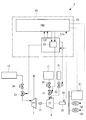
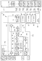
図1は、本発明の第1実施形態に係るタービン発電機系統1の概略構成を示す。本実施形態では、メインエンジン3として船舶推進用のディーゼルエンジンを用いている。
タービン発電機系統1は、メインエンジン3と、メインエンジン3の排ガスによって駆動される過給機5と、過給機5の上流側から抽気されたメインエンジン3の排ガスによって駆動されるパワータービン(ガスタービン)7と、メインエンジン3の排ガスによって蒸気を生成する排ガスエコノマイザ11と、排ガスエコノマイザ11によって生成された蒸気(高圧蒸気)によって駆動される蒸気タービン9とを備えている。
FIG. 1 shows a schematic configuration of a
The
メインエンジン3は、推進軸26の一端に直結され、この推進軸26を回転駆動させる。推進軸26の他端には、船舶の推進用プロペラ50が固定されている。メインエンジン3と推進用プロペラ50の間には、モータ46が設けられている。モータ46は、後述するタービン発電機25の出力電力が船内需用電力よりも大きい場合に、メインエンジン3を加勢する加勢モータとして機能、換言すると、負荷として機能する。また、後述するタービン発電機25の出力電力が船内需用電力よりも小さい場合に、発電機として機能し、船内需用電力を補充する。
The
メインエンジン3の各気筒のシリンダ部の排気ポートは、排ガス集合管としての排気マニホールド15に接続されている。排気マニホールド15は、第1排気管L1を介して過給機5のタービン部5aの入口側と接続されている。また、排気マニホールド15は第2排気管L2(抽気通路)を介してパワータービン7の入口側と接続され、排ガスの一部が、過給機5に供給される前に抽気されてパワータービン7に供給されるようになっている。
An exhaust port of a cylinder of each cylinder of the
過給機5は、タービン部5aと、コンプレッサ部5bと、タービン部5aとコンプレッサ部5bを連結する回転軸5cとを備えている。タービン部5aは、排気マニホールド15から排出された排ガスが第1排気管L1を介して導かれ回転駆動される。タービン部5aが回転駆動されると、同軸上に設けられたコンプレッサ部5bが回転し空気を圧縮する。圧縮された空気は、吸気管K1を通じてメインエンジン3の吸気マニホールドに供給される。吸気管K1には、空気冷却器(インタークーラ)19が設置されている。
The
パワータービン7は、第2排気管L2を介して排気マニホールド15から抽気された排ガスによって回転駆動されるようになっている。蒸気タービン9は、排ガスエコノマイザ11によって生成された蒸気が供給されて回転駆動されるようになっている。
排ガスエコノマイザ11には、過給機5のタービン部5aの出口側から第3排気管L3を介して排出される排ガスと、パワータービン7の出口側から第4排気管L4を介して排出される排ガスとが導入される。導入された排ガスは、熱交換部21において給水管23を流通する水と熱交換することにより、蒸気を発生させる。排ガスエコノマイザ11で生成された蒸気は第1蒸気管J1を介して蒸気タービン9に導入され、蒸気タービン9を回転駆動させる。蒸気タービン9で仕事を終えた蒸気は、第2蒸気管J2を通じて排出され、コンデンサ(復水器)40に導かれるようになっている。
The
The exhaust gas is discharged to the
第1蒸気管J1には、蒸気タービン9へ向かう蒸気を取り出して復水器40へと導く蒸気ダンプ配管J3が設けられている。蒸気ダンプ配管J3には、蒸気ダンプ配管J3から復水器40へ導かれる蒸気量を制御するダンプ弁41が設けられている。この蒸気ダンプ配管J3によって、蒸気タービン9に供給するには過剰とされる蒸気が蒸気タービン9をバイパスして復水器40へと廃棄される。
The first steam pipe J <b> 1 is provided with a steam dump pipe J <b> 3 that takes out steam directed to the
パワータービン7と蒸気タービン9とは直列に結合されてタービン発電機25を駆動するようになっている。蒸気タービン9の回転軸29は図示しない減速機及びカップリングを介してタービン発電機25に接続している。パワータービン7の回転軸27は図示しない減速機及びクラッチ31を介して蒸気タービン9の回転軸29と連結されている。クラッチ31としては、所定の回転数にて嵌脱されるクラッチが用いられ、例えばSSS(Synchro Self Shifting)クラッチが好適に用いられる。なお、本実施形態においては、パワータービン7と蒸気タービン9とを直列に結合してタービン発電機25を駆動するようにしているが、パワータービン7と蒸気タービン9とを並列に結合し、それぞれの回転動力から減速機を介してタービン発電機25を駆動するようにしてもよい。
タービン発電機25はコンタクタ48を介して船内電力系統42に接続可能とされている。タービン発電機25による出力電力は船内電力系統42に供給され、同じくコンタクタ48を介して船内電力系統42に接続される各種船内機器44やモータ46へ供給され、船内機器44やモータ46の駆動に用いられる。また、船内電力系統42には、コンタクタ48を介して複数(本実施形態では2台)のディーゼルエンジン発電機60が接続可能とされている。
The
The
第2排気管L2には、パワータービン7に導入するガス量を制御する排ガス量調整弁33と、非常時にパワータービン7への排ガスの供給を遮断する非常停止用緊急遮断弁36とが設けられている。
The second exhaust pipe L2 is provided with an exhaust gas
第1蒸気管J1には、蒸気タービン9に導入する蒸気量を制御する調速弁(蒸気量調整弁)37と、非常時に蒸気タービン9への蒸気の供給を遮断する非常停止用緊急遮断弁39とが設置されている。調速弁37は、後述する発電システム制御装置43(図2参照)のガバナ制御部59によって、その開度が制御される。
The first steam pipe J1 has a speed regulating valve (steam amount regulating valve) 37 for controlling the amount of steam introduced into the
以上のようにタービン発電機系統1は、メインエンジン3の排ガス(燃焼ガス)の排気エネルギーを動力として駆動されるようになっており、排気エネルギー回収装置を構成している。
As described above, the
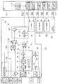
図2には、図1に示したタービン発電機系統1を有する発電システム2の概略構成が示されている。本実施形態に係る発電システム2の制御装置である発電システム制御装置43は、調速弁37の開度が所定の目標開度で一定となるように制御することで、蒸気タービン9に導入する蒸気圧を変化させる変圧運転を行う。
発電システム制御装置43には、タービン発電機25の出力電力(出力電力)を検出する電力センサ45からの信号が入力される。また、発電システム制御装置43には、ディーゼルエンジン発電機60からの出力信号と、船内消費電力を検出する船内消費電力センサ51からの信号とが入力される。
FIG. 2 shows a schematic configuration of a
A signal from a
発電システム制御装置43は、PMS(Power Management System;パワーマネジメントシステム)53と、TCP(Turbine Control Panel;タービンコントロールパネル)57aとを主な構成として備えている。PMS53及びTCP57aはいずれもコンピュータを有し、例えば、CPU、CPUが実行するプログラム及びこのプログラムにより参照されるデータ等を記憶するための補助記憶装置、各プログラム実行時のワーク領域として機能する主記憶装置、ネットワークに接続するための通信インターフェース等を有している。補助記憶装置の一例として、磁気ディスク、光磁気ディスク、半導体メモリ等が挙げられる。
The power generation
後述する各種機能を実現するための一連の処理は、一例として、プログラム(例えば、発電システム制御プログラム)の形式で補助記憶装置に記憶されており、このプログラムをCPUが主記憶装置に読み出して、情報の加工・演算処理を実行することにより、各種機能が実現される。なお、プログラムは、補助記憶装置に予めインストールされている形態や、他のコンピュータ読み取り可能な記憶媒体に記憶された状態で提供される形態、有線又は無線による通信手段を介して配信される形態等が適用されてもよい。コンピュータ読み取り可能な記憶媒体とは、磁気ディスク、光磁気ディスク、CD−ROM、DVD−ROM、半導体メモリ等である。 As an example, a series of processes for realizing various functions described later are stored in an auxiliary storage device in the form of a program (for example, a power generation system control program), and the CPU reads out the program to a main storage device, Various functions are realized by executing information processing and arithmetic processing. The program may be installed in an auxiliary storage device in advance, provided in a state stored in another computer-readable storage medium, or delivered via a wired or wireless communication unit. May be applied. The computer-readable storage medium is a magnetic disk, a magneto-optical disk, a CD-ROM, a DVD-ROM, a semiconductor memory, or the like.
TCP57aは、ガバナ制御部59を備えている。ガバナ制御部59は、調速弁37の開度制御を行う制御部である。ガバナ制御部59がPMS53から出力される開度増減のパルス信号に応じて調速弁37の弁開度を制御することで、蒸気タービン9へ供給される蒸気量が調整され、蒸気タービン9の回転数が制御される。
The
ここで、パワータービン7と蒸気タービン9とタービン発電機25は1つの軸に直列に結合されている。
発電システム制御装置43は、排ガス量調整弁33を制御するための制御部(図示略)を備えている。発電システム制御装置43は、定常運転中において、排ガス量調整弁33を全開の状態し、パワータービン7の立ち上げ及び立ち下げ時に限り、排ガス量調整弁33の開度を漸増または漸減させてもよい。パワータービンの出力が変動すると、ガバナ制御部59はその変動を吸収するように調速弁37の弁開度を制御する。
Here, the
The power generation
蒸気タービン9の中間段へは、低圧蒸気源61から混気蒸気(低圧蒸気)が供給される。混気蒸気の供給ライン上には、蒸気タービン9に導入する混気蒸気量を制御する調整弁62が設置されている。調整弁62の開度は、低圧蒸気源61での蒸気の発生量の増加及び減少に伴い、増加または減少する。混気蒸気の供給量に変化があると、ガバナ制御部59はその変動を吸収するように調速弁37の弁開度を制御する。低圧蒸気源61としては排ガスエコノマイザ11の低圧段(図1参照)が挙げられる。
Mixed steam (low-pressure steam) is supplied from a low-
次に、本実施形態に係る調速弁37の制御(ガバナ制御)について説明する。
本実施形態に係るガバナ制御では、TCP57aによって、蒸気タービン9による負荷容量値が算出され、この負荷容量値に基づいてガバナ制御部59による調速弁37の弁開度が制御される。
Next, control (governor control) of the governing
In the governor control according to the present embodiment, the load capacity value of the
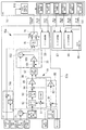
以下、図3を参照して、本実施形態に係るガバナ制御について詳細に説明する。図3は、本実施形態に係る発電システム制御装置43が備える機能のうち、ガバナ制御に係る機能を主に抽出して示した機能ブロック図である。
TCP57aは、PMS53へ出力する負荷容量値を算出する負荷容量値算出部70aを備える。負荷容量値算出部70aは、蒸気条件及び調速弁開度の少なくともいずれか一方を用いて、蒸気タービン9が出力可能な最大出力値である「負荷容量値」を算出する。負荷容量値算出部70aは、調速弁37の弁開度が全開に近い値に設定された所定の開度範囲において、負荷容量値の増減幅を他の開度範囲に比べて小さくする。
Hereinafter, the governor control according to the present embodiment will be described in detail with reference to FIG. FIG. 3 is a functional block diagram mainly extracting and showing functions related to governor control among functions provided in the power generation
The
具体的には、負荷容量値算出部70aは、設計値算出部71、第1演算部72、第2演算部73、上限値設定部74a、リミッタ部75、及び選択部76を主な構成として備えている。
Specifically, the load capacity
設計値算出部71は、負荷容量値の設計値(以下「負荷容量設計値」という。)を算出する。負荷容量設計値は、現在のメインエンジン3の運転状況に応じて理論上(設計上)求められる蒸気タービン9が出力可能な最大出力である。また、現在の運転状況に加えて環境条件を加味してもよい。設計値算出部71は、例えば、メインエンジン3の負荷(M/E Load)と外気温度(Atomos.Temp.)とを変数とする予め定められた関数を保有しており、この関数を用いて負荷容量設計値を算出する。なお、負荷容量設計値を演算する際に用いられるこれらのパラメータは一例であり、他のパラメータを加味して、より現実に則したものとされてもよい。
The design
第1演算部72は、負荷容量値を演算する。第1演算部72は、例えば、第1目標演算部80と、第2目標演算部90と、低値選択部97とを備えている。
第1目標演算部80は、調速弁開度(GV Lift)を目標開度(GV lift Setting)に近づけるための調速弁開度に基づく負荷容量値(以下「第1負荷容量値」という。)を演算する。
実施形態において、目標開度は一定値として設定され、一例として、92%に設定されている。第1目標演算部80は、調速弁開度と目標開度との開度偏差を演算する減算部81と、開度偏差に対してPID制御等を行い、開度偏差を用いて第1負荷容量値を演算するPID部82とを備える。
The
The first
In the embodiment, the target opening is set as a constant value, and is set to 92% as an example. The first
第2目標演算部90は、蒸気タービン9に供給される高圧蒸気圧(主蒸気圧)の計測値(HP Press)を蒸気圧設定値(例えば、最小設定値:HP Press Min Setting)に近づけるための蒸気圧力に基づく負荷容量値(以下「第2負荷容量値」という。)を演算する。
第2目標演算部90は、例えば、減算部91、高値選択部92、レートリミッタ93、減算部94、及びPID制御部95を備える。
減算部91は、高圧蒸気圧の計測値から予め定められた変動抑制値(規制値)を減算する。変動抑制値は、例えば0.5barである。高値選択部92は、変動抑制値が減算された高圧蒸気圧の計測値と予め設定されている高圧蒸気圧の最小設定値とを比較し、大きい方の値を選択し、レートリミッタ93に出力する。レートリミッタ93は、高値選択部92から出力された値を所定の時間変化率で変化させて減算部94に出力する。減算部94は、レートリミッタ93からの出力値と高圧蒸気の計測値との圧力偏差を演算し、PID制御部95に出力する。PID制御部95は、圧力偏差に対してPID制御を行うことにより、高圧蒸気圧を所定の蒸気圧設定値に近づけるための第2負荷容量値を演算する。
The second
The second
The subtracting
上記のように、第2目標演算部90は、減算部91、高値選択部92、及びレートリミッタ93を備えている。これら構成を備えることにより、高圧蒸気圧の計測値と蒸気圧設定値との偏差が大きい場合でも第2負荷容量値の変動量を抑制し、緩やかに変化させることが可能となる。
As described above, the second
第1目標演算部80によって算出された調速弁開度に基づく第1負荷容量値及び第2目標演算部90によって算出された蒸気圧力(蒸気条件)に基づく第2負荷容量値は、低値選択部97に出力される。低値選択部97は、両者を比較し、小さい方の値を選択し出力する。以下、低値選択部97によって選択された第1負荷容量値または第2負荷容量値を便宜上「第3負荷容量値」という。
ここで、低値選択を行っている理由は、実際の蒸気圧が設定最小値未満とならないようにするためである。すなわち、調速弁開度が開くほど蒸気圧は低下するが、蒸気圧には最小値が設定されているため、実際の蒸気圧が最小値未満となるような第1負荷容量値を負荷容量値として設定することはできない。第2負荷容量値は、蒸気圧を最小設定値に近づけるための負荷容量値であるため、常に、第2負荷容量値を超えないような第1負荷容量値を負荷容量値として選択することで、実際の蒸気圧を最小設定値以上に維持することができる。
The first load capacity value based on the governing valve opening calculated by the first
Here, the reason why the low value is selected is to prevent the actual vapor pressure from being lower than the set minimum value. That is, although the steam pressure decreases as the governing valve opening increases, the minimum value is set for the steam pressure, so that the first load capacity value at which the actual steam pressure becomes less than the minimum value is set to the load capacity. It cannot be set as a value. Since the second load capacity value is a load capacity value for bringing the vapor pressure close to the minimum set value, the first load capacity value that does not exceed the second load capacity value is always selected as the load capacity value. In addition, the actual vapor pressure can be maintained at or above the minimum set value.
設計値算出部71によって算出された負荷容量設計値(Designed
Available Power)及び第1演算部72によって演算された第3負荷容量値は、第2演算部73に出力される。
第2演算部73は、負荷容量設計値及び第3負荷容量値を用いて、負荷容量設計値を上限とした負荷容量値を演算する。第2演算部73は、例えば、減算部101、PID制御部102、及び乗算部103を備えている。
減算部101は、第3負荷容量値と乗算部103から出力された負荷容量値の前回値との偏差を演算し、PID制御部102に出力する。PID制御部102は、入力された偏差に対してPID制御を行うことで、第3負荷容量値を負荷容量値の前回値に近づけるような1以下の補正係数を演算する。乗算部103は、負荷容量設計値の今回値にPID制御部102から出力された補正係数を乗じることで、負荷容量設計値を上限とした負荷容量値(今回値)を算出する。
The load capacity design value calculated by the design value calculation unit 71 (Designed
Available Power) and the third load capacity value calculated by the
The
The
上限値設定部74aは、負荷容量値の上限値を設定する。上限値設定部74aは、現在のタービン発電機25の出力電力値と調速弁開度に応じて変化する上限パラメータとを用いて負荷容量値の上限値(以下、単に「上限値」という。)を設定する。例えば、上限値設定部74aは、図4に示すような上限パラメータ情報を有している。上限パラメータ情報は、調速弁37の弁開度と負荷容量値の増減幅とが関連付けられた情報である。上限パラメータ情報において、調速弁37の弁開度が全開に近い所定の弁開度範囲(例えば、92%から100%の範囲)における増減幅は、他の弁開度範囲における増減幅よりも小さな値に設定されている。また、所定の弁開度範囲における増減幅は、調速弁開度が全開に近づくほど小さな値とされている。なお、図4に示した上限パラメータ情報では、所定の弁開度範囲は92%以上100%以下に設定されているが、この範囲は例示であり、この例に限定されない。例えば、所定の弁開度範囲は概ね85%以上100%以下の範囲において適宜に設定可能である。
The upper limit
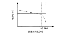
例えば、図5に示すように、全開に近いある弁開度(図5では一例として92%)未満の領域では、調速弁37の弁開度と流量との関係はほぼ比例関係にあるが、弁開度が全開に近い弁開度範囲(図5では一例として92%以上100%以下)においては流量特性が低下し、弁開度を増加させても流量がほとんど変化しなくなる。このため、例えば、調速弁37の弁開度が全開に近い弁開度範囲においては、弁開度を増加させても蒸気タービン9に供給される蒸気量を増加させることができず、この結果、蒸気タービン9による出力電力も増加させることが難しくなる。このような弁開度流量特性を考慮して、本実施形態では、調速弁開度が全開(100%)に近い所定の弁開度範囲において、負荷容量値の過剰な増加を抑制するため、上限値の増減幅を小さく設定する。
上限値設定部74aは、現在の調速弁37の弁開度に対応する増減幅を図4に示したような上限パラメータ情報から取得し、取得した増減幅を現在のタービン発電機25の出力電力値に加算することにより、負荷容量値の上限値を算出し、設定する。
For example, as shown in FIG. 5, in a region where the valve opening is close to full open and is less than 92% in FIG. In a valve opening range in which the valve opening is close to the full opening (in FIG. 5, for example, 92% or more and 100% or less), the flow characteristic is reduced, and the flow hardly changes even if the valve opening is increased. For this reason, for example, in the valve opening range in which the valve opening of the governing
The upper limit
なお、上限値設定部74aが備える上限パラメータ情報は図4に示す情報に限定されない。例えば、図6に示すように、調速弁開度と上限係数(増減率)とが関連付けられた情報であってもよい。図6に示す上限パラメータ情報は、調速弁の弁開度と上限係数とを関連付けた情報(例えば、テーブル)であり、一例として、全開(100%)のときに係数1.0とされている。
Note that the upper limit parameter information included in the upper limit
図6に示した上限パラメータ情報において、弁開度が小さくなるにつれて係数も徐々に増加する特性を有する。このように、上限係数と調速弁開度とを関連付けた上限パラメータ情報を用いる場合には、現在の調速弁37の弁開度に対応する上限係数を上限パラメータ情報から取得し、取得した上限係数をタービン発電機25の出力電力値に乗じることで上限値を算出し、設定する。
なお、調速弁開度と上限係数とを関連付けた情報は図6に示すものに限定されない。例えば、この特性は、Y軸に沿って平行移動させることも可能であり、例えば、目標開度(例えば、92%)のときに係数1.0と設定されていてもよい。
The upper limit parameter information shown in FIG. 6 has a characteristic that the coefficient gradually increases as the valve opening decreases. As described above, when the upper limit parameter information in which the upper limit coefficient and the governing valve opening are associated is used, the upper limit coefficient corresponding to the current valve opening of the
The information that associates the governing valve opening with the upper limit coefficient is not limited to that shown in FIG. For example, this characteristic can be moved in parallel along the Y axis. For example, the coefficient may be set to 1.0 at the target opening (for example, 92%).
また、上限パラメータ情報は、負荷容量値を増加させるときと、減少させるときとで異なる特性とされていてもよい。例えば、負荷容量値を低下させる場合には、上限パラメータが一定値として設定された上限パラメータ情報を用いてもよく、必ずしも図4、図6に示したように、調速弁開度が100%に近い所定の開度範囲における減少幅または減少率が他の開度範囲と比較して小さく設定される必要はない。 Further, the upper limit parameter information may have different characteristics when the load capacity value is increased and when the load capacity value is decreased. For example, when decreasing the load capacity value, upper limit parameter information in which the upper limit parameter is set as a constant value may be used, and as shown in FIGS. It is not necessary that the reduction width or the reduction rate in the predetermined opening range close to is set smaller than the other opening ranges.
上述のように、上限値設定部74aは、例えば、図4に示した上限パラメータ情報から得られた上限値の増減幅をタービン発電機25の現在の出力電力値(実出力値)に加算することで負荷容量値の上限値を算出してもよいし、図6に示したような上限パラメータ情報から得られた上限係数をタービン発電機25の現在の出力電力値(実出力値)に乗じることで負荷容量値の上限値を算出してもよい。
As described above, the upper
リミッタ部75は、第2演算部73によって演算された負荷容量値と、上限値設定部74aによって設定された上限値とを比較し、負荷容量値が上限値を超える場合には、上限値を負荷容量値として出力する。これにより、上限値設定部74aによって設定された上限値を上限とした負荷容量値が出力されることとなる。
ここで、本実施形態に係る発電システムでは、蒸気タービン9に低圧蒸気源61から低圧蒸気が供給されるため、低圧蒸気による出力電力も加味して負荷容量値を算出する必要がある。このため、例えば、第2演算部73によって演算された負荷容量値に対して、別途算出された低圧蒸気に基づく負荷容量値を加算する加算部(図示略)を有し、加算後の負荷容量値をリミッタ部75に出力することが好ましい。
The
Here, in the power generation system according to the present embodiment, since the low-pressure steam is supplied from the low-
選択部76は、モータ46がメインエンジン3を加勢する加勢モータとして駆動している場合、換言すると、タービン発電機25の出力電力が船内需用電力よりも大きいために、モータ46がタービン発電機25の余剰電力によって駆動されている場合に、リミッタ部75から出力される負荷容量値を選択する。一方、モータ46が加勢モータとして駆動していない場合に、第2演算部73によって演算された負荷容量値を選択する。
なお、モータ46はメインエンジン3を加勢する加勢モータとして駆動しているときには、ドループ機能を持たない。
When the
It should be noted that the
選択部76から出力された負荷容量値は、図示しない加算部に出力され、加算部において別途算出されたパワータービンの出力値が加算される。そして、パワータービンの出力値が加算された負荷容量値がアナログ信号としてPMS53に出力される。
The load capacity value output from the selecting
PMS53は、負荷分担制御部110及びガバナ増減パルス生成部111を備える。
負荷分担制御部110は、TCP57aから入力された負荷容量値に基づいて、蒸気タービン9及びディーゼルエンジン発電機60の負荷分担を示す負荷分担信号を生成する。ガバナ増減パルス生成部111は、負荷分担制御部110からの負荷分担信号に基づいて、蒸気タービン9及びディーゼルエンジン発電機60に対して、制御値(速度設定値)を増加又は減少させるためのガバナ増又はガバナ減を示すパルス信号(以下「ガバナ増減パルス信号」という。)を生成し、各々に対応するガバナ制御部59,87,88へ出力する。
The
The load
例えば、蒸気タービン9の回転速度を制御するガバナ制御部59は、TCP57aに備えられ、PMS53が指示する回転速度の速度設定値(ガバナ増減パルス信号)に応じて調速弁37の弁開度を増減させることで、蒸気タービン9の出力を制御するとともに、調速弁開度が目標開度となるように制御する。
For example, the
また、各ディーゼルエンジン発電機60を制御するガバナ制御部87、88は、各々対応するディーゼルエンジン発電機60に備えられ、ディーゼルエンジン発電機60の回転速度を制御する。ガバナ制御部87、88は、PMS53が指示する回転速度の速度設定値(ガバナ増減パルス信号)に応じて調速弁37の弁開度を増減させることで、ディーゼルエンジン発電機60の出力を制御する。
The
次に、本実施形態に係る発電システム制御装置(以下、単に「制御装置」という。)43による負荷変動に対する応答特性について図を参照して説明する。また、比較例として、例えば、本実施形態に係る発電システム制御装置のTCP57aにおいて、上限値設定部74aが図7に示すような上限パラメータ情報を有する場合の負荷変動に対する応答特性を想定して説明する。図7に示した比較例における上限パラメータ情報は、調速弁開度にかかわらず、増減幅が一定(例えば、400kW)とされている。なお、図7では、本実施形態に係る上限パラメータ情報と比較しやすいように、本実施形態に係る上限パラメータ特性を破線で示している。比較例として挙げた発電システム制御装置では、上限値はタービン発電機25の実出力電力値に一定値(400kW)を加算した値に設定されることとなる。
Next, a response characteristic to a load change by the power generation system control device (hereinafter, simply referred to as a “control device”) 43 according to the present embodiment will be described with reference to the drawings. Further, as a comparative example, for example, in the
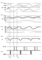
まず、比較例としての制御装置を用いた場合の負荷変動に対する各種制御量等の時間的変化について、図8を参照して説明する。図8は、調速弁37が全開に近い弁開度に設定された目標開度(例えば、92%)で制御されている場合に、船内負荷が増加した場合における各種パラメータの時間変化について示した図である。図8において、図8(a)は船内負荷の時間的変化を示したグラフであり、実線は船内負荷の消費電力、破線はモータ46の駆動に消費されるモータの消費電力、一点鎖線は船内負荷の消費電力にモータ46の消費電力を加算した船内消費電力の合計値を示している。図8(b)はタービン発電機25の出力電力を示したグラフであり、実線はタービン発電機25の実出力電力値、破線はTCPから出力される負荷容量値を示している。図8(c)は調速弁37の実弁開度を示したグラフである。図8(d)は船内電力系統の周波数を示したグラフである。図8(e)は、PMS53から調速弁37のガバナ制御部59に出力されるガバナ増減パルス信号を示したグラフである。
First, temporal changes in various control amounts and the like with respect to load fluctuation when a control device as a comparative example is used will be described with reference to FIG. FIG. 8 shows a change over time of various parameters when the load on the ship increases when the governing
図8において、時刻t1において船内負荷が増加すると(図8(a)参照)、船内電力系統42の周波数が低下する(図8(d)参照)。この周波数低下を吸収すべく、調速弁37の調速弁開度は増加する(図8(c)参照)。これは、調速弁37が有するドループ機能に基づく制御である。調速弁開度が増加することによりタービン発電機25の実出力も増加するが(図8(b)参照)、既に調速弁開度は92%で制御されているため、開度余裕が8%(=100%−92%)しかない。この8%では吸収しきれない負荷変動の場合には、調速弁開度はしばらく100%に張り付くこととなる。
8, when the load on the ship increases at time t1 (see FIG. 8A), the frequency of the
一方、調速弁開度が増加するので、TCPは調速弁開度を目標開度に近づけるべく、負荷容量値を減少させる(時刻t1〜t3)。PMS53は減少傾向にある負荷容量値に基づいて負荷分担を行い、ガバナ制御部59に対して減パルス信号を出力する(時刻t2〜t3)。これにより、調速弁開度は徐々に減少し、タービン発電機25の実出力も減少する(時刻t2〜t3)。なお、負荷容量値が減少し始めてからこれに伴う減パルス信号が出力されるまでに時間差が生じているのは(時刻t1〜t2)、制御遅れによるものである。
On the other hand, since the governing valve opening increases, the TCP reduces the load capacity value in order to bring the governing valve opening closer to the target opening (time t1 to t3). The
時刻t3において、TCPは調速弁開度が目標開度以下のため、調速弁開度を目標開度に近づけようと負荷容量値を増加させる。PMS53は増加傾向にある負荷容量値に基づいて負荷分担を行い、増パルス信号を調速弁37のガバナ制御部59に出力する(時刻t4)。これにより、調速弁開度は増加し始め、時刻t5において目標弁開度を超え、開き気味の弁開度となる。このとき、時刻t3においてTCPが負荷容量値を増加させ始めてから、時刻t5において調速弁開度が目標弁開度近くまで増加するまでに制御遅延による時間差がある(時刻t3〜t5の期間)。この間、調速弁開度は目標弁開度に達していないことから負荷容量値は増加傾向を示すわけであるが、比較例における制御装置では、上限値がタービン発電機25の実出力電力に所定値(例えば、400kW)加算した値に設定されているため、負荷容量値はこの上限値(例えば、1900kW)に達するまで増加し続ける。
これにより、PMSは増加傾向を示す負荷容量値に基づいて増パルス指令を出力し続け(時刻t4〜t5)、調速弁の弁開度は上限値に対応する開度(例えば、100%)まで上昇し続けることとなる(時刻t6)。
そして、時刻t5において、調速弁の弁開度が目標弁開度よりも大きいことから、TCPは調速弁37の弁開度を目標弁開度に近づけるべく、負荷容量値を減少させる。これに伴い、所定の時間差を持って減パルス信号が調速弁37のガバナ制御部59に出力され、調速弁開度が減少し始める。そして、上記のような制御が繰り返されることにより、調速弁開度は目標弁開度を挟んで増減を繰り返すように制御され、ハンチング現象が発生する。この結果、制御系が不安定となり、収束までに時間を要することとなる。
At time t3, the TCP increases the load capacity value so that the governing valve opening approaches the target opening because the governing valve opening is equal to or less than the target opening. The
As a result, the PMS continues to output an increasing pulse command based on the load capacity value indicating the increasing tendency (time t4 to t5), and the valve opening of the speed control valve corresponds to the upper limit (for example, 100%). (Time t6).
Then, at time t5, since the valve opening of the governing valve is larger than the target valve opening, the TCP reduces the load capacity value so that the valve opening of the governing
次に、図3に示したTCP57aを備える本実施形態に係る制御装置43を用いた場合の船内負荷変動に対する各種パラメータの時間的変化について図9を参照して説明する。図9は、調速弁37が全開に近い弁開度に設定された目標開度(例えば、92%)で制御されている場合に、船内負荷が増加した場合における各パラメータの時間変化について示した図である。図9において、図9(a)〜(e)で示されるグラフは、図8と同じ各種信号や出力を示しているため、ここでの説明は省略する。
Next, a description will be given, with reference to FIG. 9, of a temporal change of various parameters with respect to a change in the load on the ship when the
図9において、時刻t1〜t3までは上述した図8のときの時間的変化と同様であるため、説明は省略する。時刻t3において、TCP57aは調速弁開度が目標開度以下のため、調速弁開度を目標開度に近づけようと負荷容量値を増加させる。このとき、負荷容量値の上限は、例えば、図4または図6に示したように、調速弁開度に応じた増減幅または上限係数に応じて設定される。すなわち、時刻t4〜t5にかけて調速弁開度が増加するにつれ、上限値の増加幅や増加率は徐々に小さくなる。このため、図8に示した比較例による制御装置のときと異なり、負荷容量値がタービン発電機25の実出力と乖離して大きな値に設定されることを抑制することが可能となる。これにより、SPM53からガバナ制御部59に対して過剰な増パルス信号が出力されることがない。この結果、図8に示したようなハンチング現象を回避することができ、安定した制御を実現することが可能となる。
In FIG. 9, the time t1 to t3 is the same as the temporal change in FIG. 8 described above, and the description is omitted. At time t3, the
以上説明したように、本実施形態に係る発電システム及びその制御装置並びに制御方法によれば、調速弁開度が全開に近い値に設定された所定の開度範囲においては負荷容量値の増加幅又は増加率が他の開度範囲に比べて小さく設定されるので、調速弁開度が全開に近い所定開度範囲において負荷容量値と実際の発電機出力電力値とが乖離することを抑制することができる。これにより、調速弁開度が全開に近い範囲で、調速弁開度の増減が繰り返されるハンチングを抑制でき、安定した弁開度制御を実現することが可能となる。 As described above, according to the power generation system, the control device, and the control method according to the present embodiment, the load capacity value increases in a predetermined opening range in which the governing valve opening is set to a value close to full open. Since the width or increase rate is set smaller than the other opening ranges, the difference between the load capacity value and the actual generator output power value in the predetermined opening range in which the governing valve opening is close to full open. Can be suppressed. As a result, hunting in which the speed-control valve opening is repeatedly increased and decreased can be suppressed in a range where the speed-control valve opening is close to full open, and stable valve-opening control can be realized.
〔第2実施形態〕
次に、本発明の第2実施形態に係る発電システム及びその制御装置並びに制御方法について、図面を参照して説明する。本実施形態に係る発電システムは、上述した第1実施形態に係る発電システムと略同様の構成を有するが、発電システム制御装置が備えるTCPの構成が一部異なる。
以下、第1実施形態と同一の構成については同一の符号を付して説明を省略し、異なる点について主に説明する。
[Second embodiment]
Next, a power generation system, a control device thereof, and a control method according to a second embodiment of the present invention will be described with reference to the drawings. The power generation system according to the present embodiment has substantially the same configuration as the power generation system according to the above-described first embodiment, but partially differs in the configuration of the TCP included in the power generation system control device.
Hereinafter, the same components as those of the first embodiment are denoted by the same reference numerals, and description thereof will be omitted. Differences will mainly be described.
図10は本実施形態に係る発電システム制御装置が備える機能のうち、TCP57及びPMS53のガバナ制御に関する機能を主に抽出して示した機能ブロック図である。
図10に示すように、本実施形態に係るTCP57bは、負荷容量値算出部70bを備えている。負荷容量値算出部70bは、上限値設定部74bの構成が図3に示した第1実施形態に係る負荷容量値算出部70aの上限値設定部74aと異なり、他の構成については同じである。本実施形態に係る上限値設定部74bは、タービン発電機25の発電状態に影響を与える少なくとも一つのパラメータを用いて上限値を設定する。タービン発電機の発電状態に影響を与えるパラメータとして、例えば、主蒸気圧力、主蒸気温度、排ガス圧力、及び調速弁開度等が一例として挙げられる。上限値設定部74bは、タービン発電機25の発電状態に影響を与える1または複数のパラメータを変数として含む上限値演算式、または、タービン発電機25の発電状態に影響を与える1または複数のパラメータと上限値とを関連付けたテーブルやマップを保有しており、これらの情報に対して主蒸気圧力等のパラメータの計測値や制御値等を代入(入力)することにより、上限値を演算する。例えば、上限値は、主蒸気圧力が低いほど、主蒸気温度が低いほど、蒸気タービンの排気圧力が高いほど小さくなるように設定される。
このようにして算出された上限値はリミッタ部75に出力される。リミッタ部75では、第2演算部73によって算出された負荷容量値と上限値とが比較され、小さい方の値が最終的な負荷容量値として出力される。
FIG. 10 is a functional block diagram mainly extracting and showing functions related to governor control of the TCP 57 and the
As shown in FIG. 10, the
The upper limit value thus calculated is output to the
以上、説明したように、本実施形態に係る発電システム及びその制御装置並びに制御方法によれば、主蒸気圧力、主蒸気温度、排ガス圧力、及び調速弁開度等のように、発電機の発電状態に影響を与える少なくとも一つのパラメータを用いて上限値が演算されるので、現在の発電状態を加味した負荷容量値を決定することが可能となる。これにより、負荷容量値が現在の発電状態から乖離することを抑制することができ、上述した制御のハンチングなどを防止することが可能となる。これにより、船内負荷の変動に対する応答性能を向上させることが可能となる。 As described above, according to the power generation system, the control device, and the control method according to the present embodiment, the power generation system, such as the main steam pressure, the main steam temperature, the exhaust gas pressure, and the governing valve opening, is used. Since the upper limit value is calculated using at least one parameter that affects the power generation state, it is possible to determine the load capacity value in consideration of the current power generation state. As a result, it is possible to suppress the load capacity value from deviating from the current power generation state, and it is possible to prevent the above-described hunting of the control. As a result, it is possible to improve the response performance to the fluctuation of the load on the ship.
〔第3実施形態〕
次に、本発明の第3実施形態に係る発電システム及びその制御装置並びに制御方法について、図面を参照して説明する。本実施形態に係る発電システムは、上述した第2実施形態に係る発電システムと略同様の構成を有するが、発電システム制御装置が備えるTCPの構成が一部異なる。
以下、第2実施形態と同一の構成については同一の符号を付し説明を省略し、異なる点について主に説明する。
[Third embodiment]
Next, a power generation system, a control device thereof, and a control method according to a third embodiment of the present invention will be described with reference to the drawings. The power generation system according to the present embodiment has substantially the same configuration as the power generation system according to the above-described second embodiment, but partially differs in the configuration of the TCP included in the power generation system control device.
Hereinafter, the same components as those of the second embodiment are denoted by the same reference numerals, and description thereof will be omitted, and different points will be mainly described.
図11は本実施形態に係る発電システム制御装置が備える機能のうち、TCP57c及びPMS53のガバナ制御に関する機能を主に抽出して示した機能ブロック図である。
図11に示すように、本実施形態に係るTCP57cは、負荷容量値算出部70cを備えている。負荷容量値算出部70cは、設計値算出部71、第1演算部72、第2演算部73、上限値設定部74b、低値選択部200、及び選択部76aを備えている。
FIG. 11 is a functional block diagram mainly extracting and showing functions relating to governor control of the
As shown in FIG. 11, the
負荷容量値算出部70cにおいて、上限値設定部(第1上限値算出部)74bによって算出された上限値(第1上限値)、及び設計値算出部(第2上限値算出部)71によって算出された負荷容量設計値(第2上限値)は低値選択部200に出力される。低値選択部200は、これらのうち小さい方の値を選択し、上限値として出力する。
In the load capacity
選択部76aは、モータ46がメインエンジン3を加勢する加勢モータとして駆動している場合、換言すると、タービン発電機25の出力電力が船内需用電力よりも大きいために、モータ46がタービン発電機25の余剰電力によって駆動されている場合に、低値選択部200から出力される上限値を選択し、モータ46が加勢モータとして駆動していない場合に、設計値算出部71によって算出された負荷容量設計値を上限値として選択する。選択部76によって選択された上限値は、第2演算部73に出力される。
なお、モータ46はメインエンジン3を加勢する加勢モータとして駆動しているときには、ドループ機能を持たない。
When the
It should be noted that the
第2演算部73は、選択部76aから出力された上限値及び第1演算部72から出力された第3負荷容量値を用いて負荷容量値を算出する。具体的には、減算部101は、第3負荷容量値と乗算部103から出力された負荷容量値との偏差を演算し、PID制御部102に出力する。PID制御部102は、入力された偏差に対してPID制御を行うことで、第3負荷容量値を目標出力電力に近づけるような1以下の補正係数を演算する。乗算部103は、選択部76aから出力された上限値にPID制御部102から出力された補正係数を乗じることで、上限値を上限とした負荷容量値を算出する。
このようにして算出された負荷容量値には、別途算出された低圧蒸気に基づく負荷容量値及びパワータービンの出力値が加算され、最終的な負荷容量値としてPMS53に出力される。
The
The load capacity value based on the low-pressure steam and the output value of the power turbine, which are calculated separately, are added to the load capacity value calculated in this way, and output to the
以上、説明したように、本実施形態に係る発電システム及びその制御装置並びに制御方法によれば、主蒸気圧力、主蒸気温度、排ガス圧力、調速弁開度等のように、発電機の発電状態に影響を与える少なくとも一つのパラメータを用いて演算された第1上限値及びメインエンジン3の負荷及び外気温度に基づいて演算された第2上限値のうち、小さな値の方が上限値として設定され、この上限値と第3負荷容量値とから負荷容量値が演算される。このように、現在の発電状態を加味した負荷容量値を決定することが可能となる。これにより、負荷容量値が現在の発電状態から乖離することを抑制することができ、上述した制御のハンチングなどを防止することが可能となる。これにより、船内負荷の変動に対する応答性能を向上させることが可能となる。
As described above, according to the power generation system, the control device, and the control method according to the present embodiment, the power generation of the generator, such as the main steam pressure, the main steam temperature, the exhaust gas pressure, and the governing valve opening, is performed. Of the first upper limit calculated using at least one parameter affecting the state and the second upper limit calculated based on the load of the
〔第4実施形態〕
次に、本発明の第4実施形態に係る発電システム及びその制御装置並びに制御方法について、図面を参照して説明する。本実施形態に係る発電システムは、上述した第1実施形態に係る発電システムと略同様の構成を有するが、発電システム制御装置が備えるTCPの構成が一部異なる。
以下、第1実施形態と同一の構成については同一の符号を付して説明を省略し、異なる点について主に説明する。
[Fourth embodiment]
Next, a power generation system, a control device thereof, and a control method according to a fourth embodiment of the present invention will be described with reference to the drawings. The power generation system according to the present embodiment has substantially the same configuration as the power generation system according to the above-described first embodiment, but partially differs in the configuration of the TCP included in the power generation system control device.
Hereinafter, the same components as those of the first embodiment are denoted by the same reference numerals, and description thereof will be omitted. Differences will mainly be described.
図12は本実施形態に係る発電システム制御装置が備える機能のうち、TCP57d及びPMS53のガバナ制御に関する機能を主に抽出して示した機能ブロック図である。
図12に示すように、本実施形態に係るTCP57dは、負荷容量値算出部70dを備えている。負荷容量値算出部70dは、設計値算出部71、第1演算部72、第2演算部73、リミッタ部75を備えている。
FIG. 12 is a functional block diagram mainly extracting and showing functions related to governor control of the
As shown in FIG. 12, the
負荷容量値算出部70dにおいて、第2演算部73には、第1演算部72によって演算された第3負荷容量値およびタービン発電機の実出力電力値が入力される。第2演算部73は、第3負荷容量値およびタービン発電機の実出力電力値を用いて負荷容量値を演算する。具体的には、第2演算部73の減算部101は、第3負荷容量値と乗算部103から出力された負荷容量値との偏差を演算し、PID制御部102に出力する。PID制御部102は、入力された偏差に対してPID制御を行うことで、第3負荷容量値を負荷容量値に近づけるような補正係数を演算する。乗算部103は、タービン発電機の実出力電力値にPID制御部102から出力された補正係数を乗じることで負荷容量値を算出する。
In the load capacity
このようにして算出された負荷容量値は、別途算出された低圧蒸気に基づく負荷容量値が加算され、リミッタ部75に出力される。リミッタ部75には、設計値算出部71によって算出された負荷容量設計値及び第2演算部73によって演算された負荷容量値が入力される。リミッタ部75は、負荷容量値と負荷容量設計値とを比較し、負荷容量値が負荷容量設計値を超えている場合に、負荷容量設計値を負荷容量値として出力する。これにより、負荷容量設計値を上限とした負荷容量値が出力されることとなる。
リミッタ部75から出力された負荷容量値には、パワータービンの出力値が加算され、最終的な負荷容量値としてPMS53に出力される。
The load capacity value calculated in this way is added to a separately calculated load capacity value based on low-pressure steam, and output to the
The output value of the power turbine is added to the load capacity value output from the
以上、説明したように、本実施形態に係る発電システム及びその制御装置並びに制御方法によれば、タービン発電機の実際の出力を用いて負荷容量値を演算するので、負荷容量値がタービン発電機の実出力値から乖離することを抑制することが可能となり、制御のハンチングなどを防止することが可能となる。これにより、船内負荷の変動に対する応答性能を向上させることが可能となる。 As described above, according to the power generation system, the control device, and the control method according to the present embodiment, the load capacity value is calculated using the actual output of the turbine generator. Can be suppressed from deviating from the actual output value of, and control hunting and the like can be prevented. As a result, it is possible to improve the response performance to the fluctuation of the load on the ship.
以上、本発明を、上記実施形態を用いて説明したが、本発明の技術的範囲は上記実施形態に記載の範囲には限定されない。発明の要旨を逸脱しない範囲で上記実施形態に多様な変更又は改良を加えることができ、該変更又は改良を加えた形態も本発明の技術的範囲に含まれる。 As described above, the present invention has been described using the above embodiment, but the technical scope of the present invention is not limited to the scope described in the above embodiment. Various changes or improvements can be made to the above-described embodiment without departing from the spirit of the invention, and embodiments with such changes or improvements are also included in the technical scope of the present invention.
例えば、上記各実施形態では、各実施形態に係るタービン発電機系統1が舶用の発電システムとして用いられる形態について説明したが、本発明は、これに限定されるものではなく、本実施形態に係るタービン発電機系統1は、例えば陸上のプラント設備に適用される形態としてもよい。
この形態の場合、プラント設備は、無限大母線と接続されていない、所謂マイクログリッド(アイランドモードともいう。)で運用される。
For example, in each of the embodiments described above, the mode in which the
In this case, the plant equipment is operated in a so-called microgrid (also referred to as an island mode) that is not connected to the infinite bus.
また、上記実施形態では、一例として、排ガスがメインエンジン3によって生成される形態について説明したが、本発明は、これに限定されるものではなく、排ガスをメインエンジン3以外で生成される排ガス、例えば、ボイラで生成される排ガスとしてもよい。
Further, in the above-described embodiment, as an example, the form in which the exhaust gas is generated by the
1 タービン発電機系統
2 発電システム
3 メインエンジン
5 過給機
7 パワータービン
9 蒸気タービン
11 排ガスエコノマイザ
25 タービン発電機(発電機)
37 調速弁
42 船内電力系統
43 発電システム制御装置
46 モータ
53 PMS
57a〜57d TCP
59 ガバナ制御部
60 ディーゼルエンジン発電機
70a〜70d 負荷容量値算出部
71 設計値算出部
72 第1演算部
73 第2演算部
74a、74b 上限値設定部
75 リミッタ部
76、76a 選択部
80 第1目標演算部
90 第2目標演算部
200 低値選択部
DESCRIPTION OF
37
57a-57d TCP
59
Claims (18)
蒸気条件及び調速弁開度の少なくともいずれか一方を用いて前記発電機の負荷容量値を算出する負荷容量値算出部を備え、
前記負荷容量値算出部は、前記調速弁開度が全開に近い値に設定された所定の開度範囲における前記負荷容量値の増加幅又は増加率が前記調速弁開度の他の開度範囲に比べて小さくなるような前記負荷容量値を算出する発電システムの制御装置。 A control device applied to a power generation system including: a steam turbine driven by steam generated by exhaust gas; a speed control valve for controlling an amount of steam supplied to the steam turbine; and a generator connected to the steam turbine. And
A load capacity value calculation unit that calculates a load capacity value of the generator using at least one of a steam condition and a governing valve opening degree,
The load capacity value calculation unit is configured to determine whether the rate of increase or the rate of increase of the load capacity value in a predetermined opening range in which the governing valve opening is set to a value close to full opening is the other opening of the governing valve. A control device for a power generation system that calculates the load capacity value so as to be smaller than a degree range.
前記上限パラメータは、前記調速弁開度が全開に近い値に設定された前記所定の開度範囲の増加幅又は増加率が前記調速弁開度の他の開度範囲に比べて小さく設定されている請求項2に記載の発電システムの制御装置。 The load capacity value calculating unit includes an upper limit value setting unit that sets an upper limit value of the load capacity value using an upper limit parameter that changes according to the governing valve opening and an actual output power value of the generator. ,
The upper limit parameter is set such that an increasing width or an increasing rate of the predetermined opening range in which the governing valve opening is set to a value close to full opening is smaller than other opening ranges of the regulating valve opening. The control device for a power generation system according to claim 2, wherein:
蒸気条件及び調速弁開度の少なくともいずれか一方を用いて前記蒸気タービンの負荷容量値を算出する演算部と、
前記演算部によって算出された前記負荷容量値が前記上限値を超えている場合に、前記上限値を前記負荷容量値として出力するリミッタ部と
を具備する請求項3に記載の発電システムの制御装置。 The load capacity value calculation unit,
A calculating unit that calculates a load capacity value of the steam turbine using at least one of a steam condition and a governing valve opening degree;
The control device for a power generation system according to claim 3, further comprising: a limiter unit that outputs the upper limit value as the load capacity value when the load capacity value calculated by the calculation unit exceeds the upper limit value. .
前記リミッタ部は、前記モータが前記発電機の余剰出力電力によって駆動されていない状態では、前記上限値にかかわらず、前記演算部によって算出された前記負荷容量値を出力する請求項4に記載の発電システムの制御装置。 The power generation system includes a diesel engine that discharges the exhaust gas, and a motor that is provided so as to be connectable to a rotation shaft of the diesel engine and that is driven by surplus output power of the generator.
5. The limiter unit according to claim 4, wherein in a state where the motor is not driven by surplus output power of the generator, regardless of the upper limit value, the limiter unit outputs the load capacity value calculated by the calculation unit. 6. Control device for power generation system.
蒸気条件及び調速弁開度の少なくともいずれか一方を用いて前記発電機の負荷容量値を算出する負荷容量値算出部を備え、
前記負荷容量値算出部は、発電状態に影響を与えるパラメータを用いて前記負荷容量値の上限値を設定する上限値設定部を備える発電システムの制御装置。 A control device applied to a power generation system including: a steam turbine driven by steam generated by exhaust gas; a speed control valve for controlling an amount of steam supplied to the steam turbine; and a generator connected to the steam turbine. And
A load capacity value calculation unit that calculates a load capacity value of the generator using at least one of a steam condition and a governing valve opening degree,
The control device for a power generation system, wherein the load capacity value calculation unit includes an upper limit value setting unit that sets an upper limit value of the load capacity value using a parameter that affects a power generation state.
蒸気条件及び調速弁開度の少なくともいずれか一方を用いて前記蒸気タービンの負荷容量値を算出する演算部と、
前記演算部によって算出された前記負荷容量値が前記上限値を超えている場合に、前記上限値を前記負荷容量値として出力するリミッタ部と
を備える請求項6に記載の発電システムの制御装置。 The load capacity value calculation unit,
A calculating unit that calculates a load capacity value of the steam turbine using at least one of a steam condition and a governing valve opening degree;
The control device for a power generation system according to claim 6, further comprising: a limiter unit that outputs the upper limit value as the load capacity value when the load capacity value calculated by the calculation unit exceeds the upper limit value.
前記負荷容量値算出部は、前記モータが前記発電機の余剰出力電力によって駆動されていない状態では、前記上限値にかかわらず、前記演算部によって算出された前記負荷容量値を出力する請求項7に記載の発電システムの制御装置。 The power generation system includes a diesel engine that discharges the exhaust gas, and a motor that is provided so as to be connectable to a rotation shaft of the diesel engine and that is driven by surplus output power of the generator.
8. The load capacity value calculation unit outputs the load capacity value calculated by the calculation unit regardless of the upper limit value when the motor is not driven by surplus output power of the generator. A control device for a power generation system according to claim 1.
前記第1演算部によって算出された前記第1負荷容量値と、前記上限値設定部によって設定された前記上限値とを用いて、前記負荷容量値を演算する第2演算部と
を具備する請求項6に記載の発電システムの制御装置。 A first calculation unit for calculating a first load capacity value for bringing the governing valve opening closer to the target opening;
A second calculation unit configured to calculate the load capacitance value using the first load capacity value calculated by the first calculation unit and the upper limit value set by the upper limit value setting unit. Item 7. A control device for a power generation system according to item 6.
前記上限値設定部は、
発電状態に影響を与えるパラメータを用いて第1上限値を算出する第1上限値算出部と、
前記ディーゼルエンジンの負荷と外気温度とを用いて第2上限値を算出する第2上限値算出部と、
前記第1上限値と前記第2上限値のうち、小さい方の値を前記上限値として選択する低値選択部と
を備え、
前記第2演算部は、前記上限値設定部によって設定された前記上限値を用いて前記負荷容量値を算出する請求項9に記載の発電システムの制御装置。 The power generation system includes a diesel engine that discharges the exhaust gas,
The upper limit setting unit,
A first upper limit value calculation unit that calculates a first upper limit value using a parameter that affects a power generation state;
A second upper limit value calculation unit that calculates a second upper limit value using the load of the diesel engine and the outside air temperature;
A low value selection unit that selects a smaller one of the first upper limit value and the second upper limit value as the upper limit value,
The control device for a power generation system according to claim 9, wherein the second calculation unit calculates the load capacity value using the upper limit value set by the upper limit value setting unit.
前記上限値設定部は、前記加勢モータが前記発電機の余剰出力電力によって駆動されていない状態において、前記第2上限値を前記上限値として設定する請求項10に記載の発電システムの制御装置。 The power generation system includes a diesel engine that discharges the exhaust gas, and an exciting motor that is provided so as to be connectable to a rotating shaft of the diesel engine and that is driven by surplus output power of the generator.
The control device of the power generation system according to claim 10, wherein the upper limit value setting unit sets the second upper limit value as the upper limit value in a state where the boosting motor is not driven by surplus output power of the generator.
調速弁開度を目標開度に近づけるための第1負荷容量値を算出する第1演算部と、
前記第1負荷容量値と前記発電機の実出力電力値とを用いて負荷容量値を演算する第2演算部と
を備える発電システムの制御装置。 A control device applied to a power generation system including: a steam turbine driven by steam generated by exhaust gas; a speed control valve for controlling an amount of steam supplied to the steam turbine; and a generator connected to the steam turbine. And
A first calculator for calculating a first load capacity value for bringing the governing valve opening closer to the target opening;
A control device for a power generation system, comprising: a second calculation unit that calculates a load capacity value using the first load capacity value and an actual output power value of the generator.
前記ディーゼルエンジンの負荷と外気温度とを用いて前記負荷容量値の上限値を算出する上限値算出部と、
前記第2演算部によって算出された前記負荷容量値が前記上限値算出部によって算出された前記上限値を超える場合に、前記上限値を前記負荷容量値として出力するリミッタ部と
を備える請求項13に記載の発電システムの制御装置。 The power generation system includes a diesel engine that discharges the exhaust gas,
An upper limit value calculation unit that calculates an upper limit value of the load capacity value using a load of the diesel engine and an outside air temperature;
14. A limiter unit that outputs the upper limit value as the load capacity value when the load capacity value calculated by the second calculation unit exceeds the upper limit value calculated by the upper limit value calculation unit. A control device for a power generation system according to claim 1.
前記蒸気タービンに供給する蒸気量を制御する調速弁と、
前記蒸気タービンに接続された発電機と、
請求項1又は請求項6又は請求項13に記載の発電システムの制御装置と
を備える発電システム。 A steam turbine driven by steam generated by the exhaust gas,
A regulating valve for controlling the amount of steam supplied to the steam turbine,
A generator connected to the steam turbine,
A power generation system comprising: the power generation system control device according to claim 1, claim 6, or claim 13.
蒸気条件及び調速弁開度の少なくともいずれか一方を用いて前記蒸気タービンの負荷容量値を算出する目標値算出工程を有し、
前記目標値算出工程は、前記調速弁開度が全開に近い値に設定された所定の開度範囲における前記負荷容量値の増加幅又は増加率が前記調速弁開度の他の開度範囲に比べて小さくなるような前記負荷容量値を算出する発電システムの制御方法。 A control method applied to a power generation system including: a steam turbine driven by steam generated by exhaust gas; a speed control valve for controlling an amount of steam supplied to the steam turbine; and a generator connected to the steam turbine. And
A target value calculating step of calculating a load capacity value of the steam turbine using at least one of a steam condition and a governing valve opening,
The target value calculating step may include the step of increasing or decreasing the load capacity value within a predetermined opening range in which the governing valve opening is set to a value close to full opening. A method for controlling a power generation system, wherein the load capacity value is calculated to be smaller than a range.
蒸気条件及び調速弁開度の少なくともいずれか一方を用いて前記蒸気タービンの負荷容量値を算出する目標値算出工程を有し、
前記目標値算出工程は、主蒸気圧力、主蒸気温度、排気圧力の少なくとも一つを含む発電状態に影響を与えるパラメータを用いて前記負荷容量値の上限値を設定する発電システムの制御方法。 A control method applied to a power generation system including: a steam turbine driven by steam generated by exhaust gas; a speed control valve for controlling an amount of steam supplied to the steam turbine; and a generator connected to the steam turbine. And
A target value calculating step of calculating a load capacity value of the steam turbine using at least one of a steam condition and a governing valve opening,
The target value calculation step is a control method for a power generation system that sets an upper limit value of the load capacity value using a parameter that affects a power generation state including at least one of a main steam pressure, a main steam temperature, and an exhaust pressure.
調速弁開度を目標開度に近づけるための第1負荷容量値を算出する第1演算工程と、
前記第1負荷容量値と前記発電機の実出力電力値とを用いて前記発電機の負荷容量値を演算する第2演算工程と
を有する発電システムの制御方法。
A control method applied to a power generation system including: a steam turbine driven by steam generated by exhaust gas; a speed control valve for controlling an amount of steam supplied to the steam turbine; and a generator connected to the steam turbine. And
A first calculation step of calculating a first load capacity value for bringing the governing valve opening closer to the target opening;
A second calculating step of calculating a load capacity value of the generator using the first load capacity value and an actual output power value of the generator.
Priority Applications (2)
| Application Number | Priority Date | Filing Date | Title |
|---|---|---|---|
| JP2018124770A JP7150498B2 (en) | 2018-06-29 | 2018-06-29 | POWER GENERATION SYSTEM AND ITS CONTROL DEVICE AND CONTROL METHOD |
| PCT/JP2019/006502 WO2020003600A1 (en) | 2018-06-29 | 2019-02-21 | Electricity generating system, and control device and control method for same |
Applications Claiming Priority (1)
| Application Number | Priority Date | Filing Date | Title |
|---|---|---|---|
| JP2018124770A JP7150498B2 (en) | 2018-06-29 | 2018-06-29 | POWER GENERATION SYSTEM AND ITS CONTROL DEVICE AND CONTROL METHOD |
Publications (3)
| Publication Number | Publication Date |
|---|---|
| JP2020002903A true JP2020002903A (en) | 2020-01-09 |
| JP2020002903A5 JP2020002903A5 (en) | 2021-07-26 |
| JP7150498B2 JP7150498B2 (en) | 2022-10-11 |
Family
ID=68986402
Family Applications (1)
| Application Number | Title | Priority Date | Filing Date |
|---|---|---|---|
| JP2018124770A Active JP7150498B2 (en) | 2018-06-29 | 2018-06-29 | POWER GENERATION SYSTEM AND ITS CONTROL DEVICE AND CONTROL METHOD |
Country Status (2)
| Country | Link |
|---|---|
| JP (1) | JP7150498B2 (en) |
| WO (1) | WO2020003600A1 (en) |
Citations (4)
| Publication number | Priority date | Publication date | Assignee | Title |
|---|---|---|---|---|
| JPS56142201U (en) * | 1980-03-26 | 1981-10-27 | ||
| JPS6081408A (en) * | 1983-10-13 | 1985-05-09 | Toshiba Corp | Load controller in compound-cycle power plant system |
| JP2017036721A (en) * | 2015-08-14 | 2017-02-16 | 三菱重工業株式会社 | Control device of power generating system, power generating system, and power generating method |
| JP2017180406A (en) * | 2016-03-31 | 2017-10-05 | 三菱重工業株式会社 | Exhaust heat recovery system, internal combustion engine system, ship and control method for exhaust heat recovery system |
-
2018
- 2018-06-29 JP JP2018124770A patent/JP7150498B2/en active Active
-
2019
- 2019-02-21 WO PCT/JP2019/006502 patent/WO2020003600A1/en active Application Filing
Patent Citations (4)
| Publication number | Priority date | Publication date | Assignee | Title |
|---|---|---|---|---|
| JPS56142201U (en) * | 1980-03-26 | 1981-10-27 | ||
| JPS6081408A (en) * | 1983-10-13 | 1985-05-09 | Toshiba Corp | Load controller in compound-cycle power plant system |
| JP2017036721A (en) * | 2015-08-14 | 2017-02-16 | 三菱重工業株式会社 | Control device of power generating system, power generating system, and power generating method |
| JP2017180406A (en) * | 2016-03-31 | 2017-10-05 | 三菱重工業株式会社 | Exhaust heat recovery system, internal combustion engine system, ship and control method for exhaust heat recovery system |
Also Published As
| Publication number | Publication date |
|---|---|
| WO2020003600A1 (en) | 2020-01-02 |
| JP7150498B2 (en) | 2022-10-11 |
Similar Documents
| Publication | Publication Date | Title |
|---|---|---|
| JP5155977B2 (en) | Power generation system control device, power generation system, and power generation system control method | |
| JP5155980B2 (en) | Turbo compound system and operation method thereof | |
| KR101232393B1 (en) | Control method and device for turbine generator | |
| JP5138643B2 (en) | Turbine generator, turbine generator control method, control device, and ship equipped with the turbine generator | |
| CN107923258B (en) | Control device for power generation system, and power generation method | |
| JP2011027053A5 (en) | ||
| JP5232766B2 (en) | Ship engine control system | |
| WO2009084250A1 (en) | Device and method for controlling compressor | |
| KR101965122B1 (en) | Electricity generation system and electricity generation system control method | |
| WO2020003600A1 (en) | Electricity generating system, and control device and control method for same | |
| JP2013029111A (en) | Power generation method, turbine power generator, method of controlling turbine power generator, control device, and ship including the turbine power generator | |
| JP2013032153A (en) | Ship control method, and ship | |
| JP5398886B2 (en) | Power generation system control device, power generation system, and power generation method | |
| JP5675932B2 (en) | Power generation method, turbine generator, turbine generator control method, control apparatus, and ship equipped with the turbine generator |
Legal Events
| Date | Code | Title | Description |
|---|---|---|---|
| A711 | Notification of change in applicant |
Free format text: JAPANESE INTERMEDIATE CODE: A711 Effective date: 20200325 |
|
| A521 | Request for written amendment filed |
Free format text: JAPANESE INTERMEDIATE CODE: A523 Effective date: 20210514 |
|
| A621 | Written request for application examination |
Free format text: JAPANESE INTERMEDIATE CODE: A621 Effective date: 20210514 |
|
| A131 | Notification of reasons for refusal |
Free format text: JAPANESE INTERMEDIATE CODE: A131 Effective date: 20220315 |
|
| A521 | Request for written amendment filed |
Free format text: JAPANESE INTERMEDIATE CODE: A523 Effective date: 20220512 |
|
| TRDD | Decision of grant or rejection written | ||
| A01 | Written decision to grant a patent or to grant a registration (utility model) |
Free format text: JAPANESE INTERMEDIATE CODE: A01 Effective date: 20220830 |
|
| A61 | First payment of annual fees (during grant procedure) |
Free format text: JAPANESE INTERMEDIATE CODE: A61 Effective date: 20220928 |
|
| R150 | Certificate of patent or registration of utility model |
Ref document number: 7150498 Country of ref document: JP Free format text: JAPANESE INTERMEDIATE CODE: R150 |