JP2020002888A - Electric fan - Google Patents
Electric fan Download PDFInfo
- Publication number
- JP2020002888A JP2020002888A JP2018124068A JP2018124068A JP2020002888A JP 2020002888 A JP2020002888 A JP 2020002888A JP 2018124068 A JP2018124068 A JP 2018124068A JP 2018124068 A JP2018124068 A JP 2018124068A JP 2020002888 A JP2020002888 A JP 2020002888A
- Authority
- JP
- Japan
- Prior art keywords
- plate
- fan
- guard
- plates
- motor unit
- Prior art date
- Legal status (The legal status is an assumption and is not a legal conclusion. Google has not performed a legal analysis and makes no representation as to the accuracy of the status listed.)
- Pending
Links
Images


Abstract
Description
本発明は、ファンから送出される風を利用して、その風を直接浴びることで涼感を得る場合や、エアコンなどと併用して室内の空気を攪拌することで省エネ効果を得る場合に使用される扇風機に関するものである。 The present invention is used in a case where a cool feeling is obtained by directly taking the wind using a wind sent from a fan, or in a case where an energy saving effect is obtained by stirring indoor air in combination with an air conditioner or the like. Related to electric fans.
従来、扇風機は、モーター部に接続されたファンの回転により昇圧された空気が送出され、それにより発生した気流を利用して、その気流を直接浴びることで涼感を得たり、エアコンと併用して室内の気流を攪拌して温度差を抑制し、省エネに活用したりするものが知られている。 Conventionally, an electric fan is supplied with pressurized air by the rotation of a fan connected to a motor unit, and uses the generated airflow to directly take the airflow to obtain a cool feeling, or to be used together with an air conditioner. 2. Description of the Related Art There is known an apparatus that stirs an airflow in a room to suppress a temperature difference and utilize it for energy saving.
また、最近ではその気流を制御して、遠方まで風を到達させることで、広範囲に渡って涼感を得ることができる扇風機も知られている。 In recent years, there has been known an electric fan that can control the airflow and allow the wind to reach a distant place to obtain a cool feeling over a wide area.
以下、その扇風機について図5を参照しながら説明する。 Hereinafter, the electric fan will be described with reference to FIG.
図5に示すように、モーター部101と、モーター部101に回動可能に接続されたファン102と、回転しているファン102に誤って人体が接触することを抑制する目的で、ファン102を内包するガード103とを備えており、ガード103は、フロントガード105とリアガード106とから構成され、フロントガード105は、モーター部101の回転軸中心から等間隔で整流板104を備えている。
As shown in FIG. 5, a
ファン102により送出された気流は、整流板104に沿うような流れに制御され、目的の気流となりフロントガード105から前方に送出されて目的の効果を達成する。
The airflow sent out by the
このような従来の扇風機においては、整流板の形状が複雑になり、金属材料による成形や溶接では製造が難しく、大量生産には向かないため、樹脂材料による射出成型などが選択される。 In such a conventional fan, the shape of the current plate is complicated, and it is difficult to manufacture by molding or welding with a metal material, and it is not suitable for mass production. Therefore, injection molding with a resin material or the like is selected.
ここで、フロントガードはモーター部やファンの運転による振動にさらされている。 Here, the front guard is exposed to vibration caused by operation of the motor unit and the fan.
一般に、樹脂材料は金属材料に比べて、その固有振動数が低いため、扇風機の運転中にフロントガードの固有振動が励起され、振動騒音が増幅される可能性があるという課題を有していた。 In general, the resin material has a lower natural frequency than the metal material. Therefore, the natural vibration of the front guard is excited during the operation of the electric fan, and there is a problem that the vibration noise may be amplified. .
そこで本発明は、上記従来の課題を解決するものであり、運転中に樹脂製のフロントガードの固有振動が励起されることを低減し、振動騒音の増幅を抑制した扇風機を提供することを目的とする。 The present invention has been made to solve the above-mentioned conventional problems, and an object of the present invention is to provide a fan in which natural vibration of a resin front guard is reduced during operation and amplification of vibration noise is suppressed. And
そして、この目的を達成するために、本発明は、モーター部と、前記モーター部に回動可能に接続されたファンと、前記ファンを内包するガードとを備えた扇風機であって、前記ガードは、フロントガードとリアガードとから構成され、前記フロントガードは、中心板と、前記中心板よりも内径の大きな外周リングと、前記中心板の外縁から前記外周リングへ延び、等間隔に配置された複数枚の整流板と、隣り合う複数の前記整流板を連結する複数の連結板とを有し、複数の前記連結板は、互いに前記モーター部の回転軸中心からの距離が異なるように設けられたものであり、これにより所期の目的を達成するものである。 In order to achieve this object, the present invention provides a fan including a motor unit, a fan rotatably connected to the motor unit, and a guard that includes the fan. , A front guard and a rear guard, wherein the front guard includes a center plate, an outer peripheral ring having a larger inner diameter than the center plate, and a plurality of equidistantly arranged extending from the outer edge of the center plate to the outer peripheral ring. And a plurality of connecting plates for connecting adjacent ones of the straightening plates, and the plurality of connecting plates are provided so that the distances from the rotation axis center of the motor unit are different from each other. This achieves the intended purpose.
本発明によれば、フロントガードは、中心板と、中心板よりも内径の大きな外周リングと、中心板の外縁から前記外周リングへ延び、等間隔に配置された複数枚の整流板と、隣り合う複数の整流板を連結する複数の連結板とを有し、複数の前記連結板は、互いに前記モーター部の回転軸中心からの距離が異なるように設けられた構成にしたことにより、整流板を、中心板と外周リングとにより両端固定の板とみなしたとき、連結板により整流板は、中心板の外縁と外周リングとの間に固定端が設けられることになるが、連結板の位置が変わることで、それぞれの整流板は、固定端の位置が変化する。これにより、それぞれの整流板の固有振動数を変化させる。 According to the present invention, the front guard includes a center plate, an outer peripheral ring having an inner diameter larger than the center plate, a plurality of straightening plates extending from the outer edge of the center plate to the outer peripheral ring, and arranged at equal intervals. A plurality of connecting plates for connecting a plurality of matching rectifying plates, wherein the plurality of connecting plates are provided so as to have different distances from the rotation axis center of the motor unit. When the plate is regarded as a plate fixed at both ends by the center plate and the outer peripheral ring, the rectifying plate is provided with a fixed end between the outer edge of the center plate and the outer peripheral ring by the connecting plate. As a result, the position of the fixed end of each current plate changes. Thereby, the natural frequency of each current plate is changed.
そのため、フロントガードが、ファンやモーター部の振動を受けた場合であっても、整流板はそれぞれ固有振動数が異なるため、フロントガードの振動が抑制され、扇風機の振動騒音が低減されるという効果を得ることができる。 Therefore, even when the front guard receives vibration from the fan and motor, the straightening plates have different natural frequencies, so that the front guard is suppressed and the fan noise is reduced. Can be obtained.
本発明の請求項1記載の扇風機は、モーター部と、前記モーター部に回動可能に接続されたファンと、前記ファンを内包するガードとを備えた扇風機であって、前記ガードは、フロントガードとリアガードとから構成され、前記フロントガードは、中心板と、前記中心板よりも内径の大きな外周リングと、前記中心板の外縁から前記外周リングへ延び、等間隔に配置された複数枚の整流板と、隣り合う複数の前記整流板を連結する複数の連結板とを有し、複数の前記連結板は、互いに前記モーター部の回転軸中心からの距離が異なるように設けられた構成を有する。これにより、前記整流板を、前記中心板と前記外周リングとにより両端固定の板とみなしたとき、前記連結板により前記整流板は、前記中心板の外縁と前記外周リングとの間に固定端が設けられることになるが、前記連結板の位置が変わることで、それぞれの前記整流板は、前記固定端の位置が変化する。これにより、それぞれの前記整流板の固有振動数を変化させるので、前記フロントガードが、前記ファンや前記モーター部の振動を受けた場合であっても、前記整流板はそれぞれ固有振動数が異なるため、前記フロントガードの振動を抑制し、扇風機の振動騒音を低減するという効果を奏する。 The fan according to claim 1 of the present invention is a fan including a motor unit, a fan rotatably connected to the motor unit, and a guard that includes the fan, wherein the guard is a front guard. And a rear guard, wherein the front guard includes a center plate, an outer peripheral ring having an inner diameter larger than the center plate, and a plurality of rectifiers extending from an outer edge of the center plate to the outer peripheral ring and arranged at equal intervals. A plate, and a plurality of connecting plates that connect the plurality of adjacent rectifying plates, and the plurality of connecting plates has a configuration in which the distances from the rotation axis center of the motor unit are different from each other. . Thus, when the rectifying plate is regarded as a plate fixed at both ends by the center plate and the outer peripheral ring, the rectifying plate is fixed between the outer edge of the center plate and the outer peripheral ring by the connecting plate. However, when the position of the connecting plate changes, the position of the fixed end of each rectifying plate changes. Thereby, since the natural frequency of each of the rectifying plates is changed, even when the front guard receives vibration of the fan or the motor unit, the rectifying plates have different natural frequencies. This has the effect of suppressing the vibration of the front guard and reducing the vibration noise of the electric fan.
また、前記連結板を不連続に複数設けた構成にしてもよい。これにより、複数の前記連結板の位置を任意に変えることで、それぞれの前記整流板の固有振動も任意に変化させるので、それぞれの前記整流板の固有振動を大きくずらすことも可能となり、前記フロントガードの振動をより効果的に抑制するという効果を奏する。 Further, a configuration in which a plurality of the connection plates are provided discontinuously may be employed. Thereby, by arbitrarily changing the positions of the plurality of connecting plates, the natural vibration of each of the rectifying plates is also arbitrarily changed. This has the effect of suppressing the vibration of the guard more effectively.
また、モーター部と、前記モーター部に回動可能に接続されたファンと、前記ファンを内包するガードとを備えた扇風機であって、前記ガードは、フロントガードとリアガードとから構成され、前記フロントガードは、中心板と、前記中心板よりも内径の大きな外周リングと、前記中心板の外縁から前記外周リングへ延び、等間隔に配置された複数枚の整流板と、隣り合う複数の前記整流板を連結する連結板とを有し、前記連結板は、前記モーター部の回転軸中心からの距離が変化するように設けられた構成を有する。これにより、前記整流板を、前記中心板と前記外周リングとにより両端固定の板とみなしたとき、前記連結板により前記整流板は、前記中心板の外縁と前記外周リングとの間に固定端が設けられることになるが、前記連結板の位置が変わることで、それぞれの前記整流板は、前記固定端の位置が変化する。これにより、それぞれの前記整流板の固有振動数を変化させるので、前記フロントガードが、前記ファンや前記モーター部の振動を受けた場合であっても、前記整流板はそれぞれ固有振動数が異なるため、前記フロントガードの振動を抑制し、扇風機の振動騒音を低減するという効果を奏する。また、前記整流板を連続して連結することにより、前記フロントガードの強度を向上させるという効果を奏する。 Further, the electric fan includes a motor unit, a fan rotatably connected to the motor unit, and a guard including the fan, wherein the guard includes a front guard and a rear guard, The guard includes a center plate, an outer peripheral ring having an inner diameter larger than the center plate, a plurality of rectifying plates extending from an outer edge of the center plate to the outer peripheral ring, and arranged at regular intervals, and a plurality of adjacent rectifying plates. A connection plate for connecting the plates, wherein the connection plate is provided such that a distance from a center of a rotation axis of the motor unit changes. Thus, when the rectifying plate is regarded as a plate fixed at both ends by the center plate and the outer peripheral ring, the rectifying plate is fixed between the outer edge of the center plate and the outer peripheral ring by the connecting plate. However, when the position of the connecting plate changes, the position of the fixed end of each rectifying plate changes. Thereby, since the natural frequency of each of the rectifying plates is changed, even when the front guard receives vibration of the fan or the motor unit, the rectifying plates have different natural frequencies. This has the effect of suppressing the vibration of the front guard and reducing the vibration noise of the electric fan. Further, by connecting the straightening plates continuously, there is an effect that the strength of the front guard is improved.
以下、本発明の実施の形態について図面を参照しながら説明する。 Hereinafter, embodiments of the present invention will be described with reference to the drawings.
(実施の形態1)
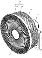
図1に示すように、扇風機1は、モーター部2と、軸流ファン3と、ガード部4とを備えている。
(Embodiment 1)
As shown in FIG. 1, the electric fan 1 includes a motor unit 2, an
モーター部2は、通電により回動する回転軸(図示せず)を備えており、軸流ファン3は回転軸に固定されている。
The motor unit 2 has a rotating shaft (not shown) that rotates when energized, and the
ガード部4は、フロントガード5と、リアガード6とを備え、リアガード6は、フロントガード5に設けたツメ(図示せず)に嵌合して、軸流ファン3を内包する。
The
リアガード6は、金属製の線材に対して曲げるなどの加工を施したあと、溶接などにより構成され、モーター部2の前面に、ネジ(図示せず)などによって固定される。
The
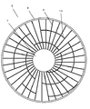
図2に示すように、フロントガード5は、樹脂材料(たとえば、ポリプロピレン(PP))であり、中心板7と、外周リング8と、整流板9と、連結板10とを備えている。
As shown in FIG. 2, the
中心板7は、円板形状であり、扇風機1を正面から見ると、フロントガード5の中央部に配置されている。中心板7の中心軸が、モーター部2の回転軸と同軸上に配置されている。
The center plate 7 has a disk shape, and is disposed at the center of the
整流板9は、細長板形状であり、中心板7の外縁から等間隔に外方へ延びている。中心板7の外縁から外方へ延びた方向が、整流板9の長辺方向である。中心板7の外縁から外方へ延びた整流板9の先端は、外周リング8に固定されている。
The current plate 9 has an elongated plate shape and extends outward from the outer edge of the center plate 7 at equal intervals. The direction extending outward from the outer edge of the center plate 7 is the long side direction of the current plate 9. The end of the current plate 9 extending outward from the outer edge of the center plate 7 is fixed to the outer
外周リング8は、円環形状であり、外周リング8の内径は、中心板7の外径よりも大きい。中心板7の外縁から延びた整流板9の先端は、外周リング8の内面に固定されている。
The
連結板10は、細長板形状であり、整流板9と交差するように延び、隣り合う複数の整流板9を連結している。細長板形状の連結板10における短辺方向は、モーター部2の回転軸方向である。なお、中心板7と、外周リング8と、整流板9と、連結板10とは、一体で形成している(たとえば、射出成型など)。
The connecting
以上のように、フロントガード5は、中心板7と、中心板7よりも外径の大きな外周リング8と、中心板7の外縁から外周リング8へ向けて、等間隔に、板状の複数枚の整流板9が外周リング8に接続され、隣り合う複数の整流板9に連結する連結板10が、互いにモーター部2の回転軸中心からの距離が異なるように設けられている。
As described above, the
具体的には、連結板10は、モーター部2の回転軸を中心点とした円弧状の板であり、ここでは5枚を配設している。それぞれの連結板10の位置は、モーター部2の回転軸から半径R1、R2、R3、R4、R5として表される。ここで、R1、R2、R3、R4、R5はいずれも異なる値とする。また、それぞれの連結板10の円弧の長さは、C1、C2、C3、C4、C5として表される。ここで、C1、C2、C3、C4、C5はいずれも異なる値とする。また、5枚のそれぞれの連結板10は、互いが隣り合わないように、整流板9に設けられている。なお、モーター部2の回転軸から複数の連結板10までの距離が半径R1、R2、R3、R4、R5のように、それぞれの距離が異なり、5枚のそれぞれの連結板10は、互いが隣り合わないように配置された場合は、連結板10を不連続に複数設けた構成である。
Specifically, the connecting
連結板10を配設したことにより、整流板9は、中心板7と連結板10に支持される部分と、連結板10と外周リング8に支持される部分とに分けることができる。連結板10により分けられていない整流板9の長さをL0、連結板10により分けられた整流板9の長さをL1、L2、L3、L4、L5、L6、L7、L8、L9、L10としたとき、いずれも異なる値となる。
By arranging the connecting
このような構成によれば、軸流ファン3の回転により昇圧された空気は気流となって、モーター部2より前方に送出される。ガード部4は、軸流ファン3を内包しているため、ユーザーが回転している軸流ファン3に誤って接触することを抑制する。
According to such a configuration, the air pressurized by the rotation of the
気流は、フロントガード5に備わる整流板9を通過して、所望の気流へと変化したあと、フロントガード5より前方へ送出される。
The airflow passes through the flow straightening plate 9 provided in the
このとき、モーター部2や、軸流ファン3は振動しており、その振動はフロントガード5にも伝播する。整流板9は、中心板7と外周リング8とに接続されているので、両端固定の状態となっている。一般的にポリプロピレンのような樹脂材料は固有振動数が低いところに存在する。このため、モーター部2や、軸流ファン3の振動に励起されて、中心板7と外周リング8との間で、整流板9が固有振動することが考えられる。とくに、モーター部2の出力を制御して、軸流ファン3の回転数を変化させることで気流の量を調整できる場合には、その調整中や調整後に整流板9の固有値に合致して固有振動が励起される可能性もある。
At this time, the motor unit 2 and the
ここで、整流板9については両端固定の板と見立てることができる。そのとき、固有振動数fは、f=λ/(2・π・L)・√(E/ρ)と表すことができる。Eは整流板9の材料の縦弾性係数(ヤング率)、ρは整流板9の材料の密度、Lは整流板9の弦の長さ、λは固有振動のモードによって決まる定数である。 Here, the current plate 9 can be regarded as a plate fixed at both ends. At that time, the natural frequency f can be expressed as f = λ / (2 · π · L) · √ (E / ρ). E is the modulus of longitudinal elasticity (Young's modulus) of the material of the current plate 9, ρ is the density of the material of the current plate 9, L is the length of the chord of the current plate 9, and λ is a constant determined by the mode of natural vibration.
連結板10により、整流板9は各々長さの異なる板であることから、固有振動も各々に異なる数値となる。このため、モーター部2や軸流ファン3の振動がフロントガード5に伝播した場合でも、整流板9は連結板10により固有振動数を変えることができるので、フロントガード5が全体で固有振動することを低減することができる。
Since the straightening plates 9 are plates having different lengths due to the connecting
そのため、軸流ファン3を一定の回転数で運転させるときや、風量を調節するために軸流ファン3の回転数を変化させたとき、いずれかの整流板9の固有振動数に合致したとしても、フロントガード5が全体で固有振動することを低減することができるので、扇風機1の運転中の振動騒音を抑制することができる。
Therefore, when the
(実施の形態2)
図3において、図1および図2と同様の構成要素については同一の符号を付し、その詳細な説明は省略する。
(Embodiment 2)
3, the same components as those in FIGS. 1 and 2 are denoted by the same reference numerals, and detailed description thereof will be omitted.
図3に示す連結板10は、隣り合う複数の整流板9に連結する連結板10が、モーター部の回転軸中心からの距離が変化するように設けられた構成である。具体的には、連結板10は、アルキメデス螺旋を参考にした渦巻き状で、中心軸からの半径が連続的に変化する形状である。
The connecting
整流板9は、中心板7と連結板10とに支持される部分と、連結板10の間で支持される部分と、連結板10と外周リング8とに支持される部分に分けられる。
The current plate 9 is divided into a portion supported by the center plate 7 and the connecting
このような構成において、整流板9の弦の長さLは連続的に変化するため、各々の整流板9の固有振動数も連続的に変化させることができる。そのため、軸流ファン3を一定の回転数で運転させるときや、風量を調節するために軸流ファン3の回転数を変化させたとき、いずれかの整流板9の固有振動数に合致したとしても、フロントガード5が全体で固有振動することを低減することができるので、扇風機1の運転中の振動騒音を抑制することができる。また、整流板9は連続して連結されているため、フロントガード5の強度を向上させる効果がある。
In such a configuration, the string length L of the current plate 9 changes continuously, so that the natural frequency of each current plate 9 can also be changed continuously. Therefore, when the
(実施の形態3)
図4において、図1から図3と同様の構成要素については同一の符号を付し、その詳細な説明は省略する。
(Embodiment 3)
4, the same components as those in FIGS. 1 to 3 are denoted by the same reference numerals, and a detailed description thereof will be omitted.
図4に示す連結板10は、実施の形態2において示した渦巻き状の一部を省き、不連続に設けた構成とした形状である。
The connecting
このような構成においても、連結板10が配置されている部分の整流板9の弦の長さLは連続的に変化するため、各々の整流板9の固有振動数も連続的に変化させることができる。そのため、軸流ファン3を一定の回転数で運転させるときや、風量を調節するために軸流ファン3の回転数を変化させたとき、いずれかの整流板9の固有振動数に合致したとしても、フロントガード5が全体で固有振動することを低減することができるので、扇風機1の運転中の振動騒音を抑制することができる。
Even in such a configuration, since the chord length L of the rectifying plate 9 at the portion where the connecting
なお、実施の形態2および実施の形態3では、連結板10について、モーター部2の回転軸からの距離の変化の説明について、アルキメデス螺旋を参考として表現しているが、この例に限らず任意の曲線を用いて、整流板9の固有振動数を変化させてもよく、その作用効果に差異を生じない。
In the second and third embodiments, the description of the change in the distance from the rotation axis of the motor unit 2 with respect to the connecting
本発明にかかる扇風機は、運転中の振動がフロントガードに伝播して、その振動に固有振動が励起されて、振動騒音が大きくなることを抑制することを可能とするものであるので、一般的な家屋やフードコートなどに設置され、直接に気流を浴びて涼感を得る場合や、空気を攪拌して温度差を抑制する場合に使用される扇風機等として有用である。 The fan according to the present invention is capable of suppressing vibration during operation from propagating to the front guard, thereby exciting natural vibration to the vibration and increasing vibration noise. It is installed in a small house or food court, and is useful as a fan or the like that is used when a bath is directly exposed to airflow to obtain a cool feeling, or when air is stirred to suppress a temperature difference.
1 扇風機
2 モーター部
3 軸流ファン
4 ガード部
5 フロントガード
6 リアガード
7 中心板
8 外周リング
9 整流板
10 連結板
DESCRIPTION OF SYMBOLS 1 Fan 2
Claims (4)
前記モーター部に回動可能に接続されたファンと、
前記ファンを内包するガードとを備えた扇風機であって、
前記ガードは、
フロントガードとリアガードとから構成され、
前記フロントガードは、
中心板と、
前記中心板よりも内径の大きな外周リングと、
前記中心板の外縁から前記外周リングへ延び、等間隔に配置された複数枚の整流板と、
隣り合う複数の前記整流板を連結する複数の連結板とを有し、
複数の前記連結板は、互いに前記モーター部の回転軸中心からの距離が異なるように設けられたことを特徴とする扇風機。 Motor part,
A fan rotatably connected to the motor unit,
A fan with a guard that contains the fan,
The guard is
It consists of a front guard and a rear guard,
The front guard,
A center plate,
An outer peripheral ring having a larger inner diameter than the center plate;
A plurality of straightening plates extending from the outer edge of the center plate to the outer peripheral ring and arranged at equal intervals;
A plurality of connecting plates for connecting a plurality of adjacent straightening plates,
The electric fan, wherein the plurality of connection plates are provided so as to have different distances from the center of the rotation axis of the motor unit.
前記モーター部に回動可能に接続されたファンと、
前記ファンを内包するガードとを備えた扇風機であって、
前記ガードは、
フロントガードとリアガードとから構成され、
前記フロントガードは、
中心板と、
前記中心板よりも内径の大きな外周リングと、
前記中心板の外縁から前記外周リングへ延び、等間隔に配置された複数枚の整流板と、
隣り合う複数の前記整流板を連結する連結板とを有し、
前記連結板は、前記モーター部の回転軸中心からの距離が変化するように設けられたことを特徴とする扇風機。 Motor part,
A fan rotatably connected to the motor unit,
A fan with a guard that contains the fan,
The guard is
It consists of a front guard and a rear guard,
The front guard,
A center plate,
An outer peripheral ring having a larger inner diameter than the center plate;
A plurality of straightening plates extending from the outer edge of the center plate to the outer peripheral ring and arranged at equal intervals;
And a connecting plate for connecting a plurality of the straightening plates adjacent to each other,
The electric fan, wherein the connection plate is provided such that a distance from a center of a rotation axis of the motor unit changes.
Priority Applications (1)
| Application Number | Priority Date | Filing Date | Title |
|---|---|---|---|
| JP2018124068A JP2020002888A (en) | 2018-06-29 | 2018-06-29 | Electric fan |
Applications Claiming Priority (1)
| Application Number | Priority Date | Filing Date | Title |
|---|---|---|---|
| JP2018124068A JP2020002888A (en) | 2018-06-29 | 2018-06-29 | Electric fan |
Publications (1)
| Publication Number | Publication Date |
|---|---|
| JP2020002888A true JP2020002888A (en) | 2020-01-09 |
Family
ID=69099824
Family Applications (1)
| Application Number | Title | Priority Date | Filing Date |
|---|---|---|---|
| JP2018124068A Pending JP2020002888A (en) | 2018-06-29 | 2018-06-29 | Electric fan |
Country Status (1)
| Country | Link |
|---|---|
| JP (1) | JP2020002888A (en) |
Citations (9)
| Publication number | Priority date | Publication date | Assignee | Title |
|---|---|---|---|---|
| JPS5146565A (en) * | 1974-10-18 | 1976-04-21 | Matsushita Refrigeration | Hogogaadobanno seizohoho |
| JPH0783002A (en) * | 1993-09-17 | 1995-03-28 | Hitachi Ltd | Fluid machine and blade device of fluid machine |
| JPH08319988A (en) * | 1995-05-23 | 1996-12-03 | Mitsubishi Electric Corp | Ventilation fan |
| JP2004270701A (en) * | 2003-03-05 | 2004-09-30 | Halla Climate Control Corp | Axial fan |
| JP2004353628A (en) * | 2003-05-30 | 2004-12-16 | Kujiyaku Kinmo Kk | Electric fan |
| US20050271529A1 (en) * | 2004-04-26 | 2005-12-08 | Behr Gmbh & Co.Kg | Fan housing for a heat exchanger, particular for motor vehicles |
| WO2016121485A1 (en) * | 2015-01-26 | 2016-08-04 | シャープ株式会社 | Fan guard and blower device |
| WO2017026143A1 (en) * | 2015-08-10 | 2017-02-16 | 三菱電機株式会社 | Blower and air-conditioning device |
| WO2017086123A1 (en) * | 2015-11-18 | 2017-05-26 | 日本電産テクノモータ株式会社 | Fan unit and outdoor unit |
-
2018
- 2018-06-29 JP JP2018124068A patent/JP2020002888A/en active Pending
Patent Citations (9)
| Publication number | Priority date | Publication date | Assignee | Title |
|---|---|---|---|---|
| JPS5146565A (en) * | 1974-10-18 | 1976-04-21 | Matsushita Refrigeration | Hogogaadobanno seizohoho |
| JPH0783002A (en) * | 1993-09-17 | 1995-03-28 | Hitachi Ltd | Fluid machine and blade device of fluid machine |
| JPH08319988A (en) * | 1995-05-23 | 1996-12-03 | Mitsubishi Electric Corp | Ventilation fan |
| JP2004270701A (en) * | 2003-03-05 | 2004-09-30 | Halla Climate Control Corp | Axial fan |
| JP2004353628A (en) * | 2003-05-30 | 2004-12-16 | Kujiyaku Kinmo Kk | Electric fan |
| US20050271529A1 (en) * | 2004-04-26 | 2005-12-08 | Behr Gmbh & Co.Kg | Fan housing for a heat exchanger, particular for motor vehicles |
| WO2016121485A1 (en) * | 2015-01-26 | 2016-08-04 | シャープ株式会社 | Fan guard and blower device |
| WO2017026143A1 (en) * | 2015-08-10 | 2017-02-16 | 三菱電機株式会社 | Blower and air-conditioning device |
| WO2017086123A1 (en) * | 2015-11-18 | 2017-05-26 | 日本電産テクノモータ株式会社 | Fan unit and outdoor unit |
Similar Documents
| Publication | Publication Date | Title |
|---|---|---|
| US6514036B2 (en) | Radial flow fan with impeller having blade configuration for noise reduction | |
| US9745996B2 (en) | Fan | |
| US10184490B2 (en) | Noise reduction diffuser for an electric blower | |
| GB2502103A (en) | Bladeless fan | |
| US9980549B2 (en) | Hair dryer | |
| US20160213122A1 (en) | Hair dryer | |
| JP6303461B2 (en) | Impeller and blower | |
| US10935039B2 (en) | Blower impeller for a handheld blower | |
| JP2022500590A (en) | Forward / reverse rotation fan | |
| KR20160063743A (en) | Fan assembly for centrifugal blower and air conditioning equipment having the same | |
| CA2777140A1 (en) | An axial fan, fan rotor and method of manufacturing a rotor for an axial fan | |
| JP2020002888A (en) | Electric fan | |
| JP2006322378A (en) | Blower impeller | |
| JP2019002395A (en) | Air blower | |
| JP7355755B2 (en) | debris blower | |
| CN109083853A (en) | A kind of blower fan structure and air conditioner | |
| JP4872997B2 (en) | Blower and air conditioner equipped with the blower | |
| Hurtado et al. | Design of low speed rim driven ventilation fan for minimum noise | |
| JP2009030520A (en) | Blower fan and blower | |
| JP2728855B2 (en) | Sound conditioning type blower | |
| TWI465647B (en) | Piezoelectric fan | |
| CN220452243U (en) | Handheld fan | |
| JP2019002378A (en) | Propeller fan | |
| JP2013228168A (en) | Air conditioner | |
| JP2009203908A (en) | Blower and air conditioner provided with blower |
Legal Events
| Date | Code | Title | Description |
|---|---|---|---|
| RD01 | Notification of change of attorney |
Free format text: JAPANESE INTERMEDIATE CODE: A7421 Effective date: 20190123 |
|
| A621 | Written request for application examination |
Free format text: JAPANESE INTERMEDIATE CODE: A621 Effective date: 20210525 |
|
| A977 | Report on retrieval |
Free format text: JAPANESE INTERMEDIATE CODE: A971007 Effective date: 20220304 |
|
| A131 | Notification of reasons for refusal |
Free format text: JAPANESE INTERMEDIATE CODE: A131 Effective date: 20220315 |
|
| A02 | Decision of refusal |
Free format text: JAPANESE INTERMEDIATE CODE: A02 Effective date: 20220913 |