JP2019532729A - Tissue repair device - Google Patents
Tissue repair device Download PDFInfo
- Publication number
- JP2019532729A JP2019532729A JP2019520131A JP2019520131A JP2019532729A JP 2019532729 A JP2019532729 A JP 2019532729A JP 2019520131 A JP2019520131 A JP 2019520131A JP 2019520131 A JP2019520131 A JP 2019520131A JP 2019532729 A JP2019532729 A JP 2019532729A
- Authority
- JP
- Japan
- Prior art keywords
- implant
- needle
- ratchet
- repair device
- suture
- Prior art date
- Legal status (The legal status is an assumption and is not a legal conclusion. Google has not performed a legal analysis and makes no representation as to the accuracy of the status listed.)
- Pending
Links
Images


Classifications
-
- A—HUMAN NECESSITIES
- A61—MEDICAL OR VETERINARY SCIENCE; HYGIENE
- A61B—DIAGNOSIS; SURGERY; IDENTIFICATION
- A61B17/00—Surgical instruments, devices or methods, e.g. tourniquets
- A61B17/04—Surgical instruments, devices or methods, e.g. tourniquets for suturing wounds; Holders or packages for needles or suture materials
- A61B17/0491—Sewing machines for surgery
-
- A—HUMAN NECESSITIES
- A61—MEDICAL OR VETERINARY SCIENCE; HYGIENE
- A61B—DIAGNOSIS; SURGERY; IDENTIFICATION
- A61B17/00—Surgical instruments, devices or methods, e.g. tourniquets
- A61B17/04—Surgical instruments, devices or methods, e.g. tourniquets for suturing wounds; Holders or packages for needles or suture materials
- A61B17/0401—Suture anchors, buttons or pledgets, i.e. means for attaching sutures to bone, cartilage or soft tissue; Instruments for applying or removing suture anchors
-
- A—HUMAN NECESSITIES
- A61—MEDICAL OR VETERINARY SCIENCE; HYGIENE
- A61B—DIAGNOSIS; SURGERY; IDENTIFICATION
- A61B17/00—Surgical instruments, devices or methods, e.g. tourniquets
- A61B17/04—Surgical instruments, devices or methods, e.g. tourniquets for suturing wounds; Holders or packages for needles or suture materials
- A61B17/0469—Suturing instruments for use in minimally invasive surgery, e.g. endoscopic surgery
-
- A—HUMAN NECESSITIES
- A61—MEDICAL OR VETERINARY SCIENCE; HYGIENE
- A61B—DIAGNOSIS; SURGERY; IDENTIFICATION
- A61B17/00—Surgical instruments, devices or methods, e.g. tourniquets
- A61B17/04—Surgical instruments, devices or methods, e.g. tourniquets for suturing wounds; Holders or packages for needles or suture materials
- A61B17/06—Needles ; Sutures; Needle-suture combinations; Holders or packages for needles or suture materials
- A61B17/06066—Needles, e.g. needle tip configurations
-
- A—HUMAN NECESSITIES
- A61—MEDICAL OR VETERINARY SCIENCE; HYGIENE
- A61B—DIAGNOSIS; SURGERY; IDENTIFICATION
- A61B17/00—Surgical instruments, devices or methods, e.g. tourniquets
- A61B17/04—Surgical instruments, devices or methods, e.g. tourniquets for suturing wounds; Holders or packages for needles or suture materials
- A61B17/0482—Needle or suture guides
-
- A—HUMAN NECESSITIES
- A61—MEDICAL OR VETERINARY SCIENCE; HYGIENE
- A61B—DIAGNOSIS; SURGERY; IDENTIFICATION
- A61B17/00—Surgical instruments, devices or methods, e.g. tourniquets
- A61B2017/00367—Details of actuation of instruments, e.g. relations between pushing buttons, or the like, and activation of the tool, working tip, or the like
- A61B2017/00407—Ratchet means
-
- A—HUMAN NECESSITIES
- A61—MEDICAL OR VETERINARY SCIENCE; HYGIENE
- A61B—DIAGNOSIS; SURGERY; IDENTIFICATION
- A61B17/00—Surgical instruments, devices or methods, e.g. tourniquets
- A61B17/04—Surgical instruments, devices or methods, e.g. tourniquets for suturing wounds; Holders or packages for needles or suture materials
- A61B17/0401—Suture anchors, buttons or pledgets, i.e. means for attaching sutures to bone, cartilage or soft tissue; Instruments for applying or removing suture anchors
- A61B2017/0409—Instruments for applying suture anchors
-
- A—HUMAN NECESSITIES
- A61—MEDICAL OR VETERINARY SCIENCE; HYGIENE
- A61B—DIAGNOSIS; SURGERY; IDENTIFICATION
- A61B17/00—Surgical instruments, devices or methods, e.g. tourniquets
- A61B17/04—Surgical instruments, devices or methods, e.g. tourniquets for suturing wounds; Holders or packages for needles or suture materials
- A61B17/0401—Suture anchors, buttons or pledgets, i.e. means for attaching sutures to bone, cartilage or soft tissue; Instruments for applying or removing suture anchors
- A61B2017/0414—Suture anchors, buttons or pledgets, i.e. means for attaching sutures to bone, cartilage or soft tissue; Instruments for applying or removing suture anchors having a suture-receiving opening, e.g. lateral opening
-
- A—HUMAN NECESSITIES
- A61—MEDICAL OR VETERINARY SCIENCE; HYGIENE
- A61B—DIAGNOSIS; SURGERY; IDENTIFICATION
- A61B17/00—Surgical instruments, devices or methods, e.g. tourniquets
- A61B17/04—Surgical instruments, devices or methods, e.g. tourniquets for suturing wounds; Holders or packages for needles or suture materials
- A61B17/0401—Suture anchors, buttons or pledgets, i.e. means for attaching sutures to bone, cartilage or soft tissue; Instruments for applying or removing suture anchors
- A61B2017/0417—T-fasteners
-
- A—HUMAN NECESSITIES
- A61—MEDICAL OR VETERINARY SCIENCE; HYGIENE
- A61B—DIAGNOSIS; SURGERY; IDENTIFICATION
- A61B17/00—Surgical instruments, devices or methods, e.g. tourniquets
- A61B17/04—Surgical instruments, devices or methods, e.g. tourniquets for suturing wounds; Holders or packages for needles or suture materials
- A61B17/0401—Suture anchors, buttons or pledgets, i.e. means for attaching sutures to bone, cartilage or soft tissue; Instruments for applying or removing suture anchors
- A61B2017/0464—Suture anchors, buttons or pledgets, i.e. means for attaching sutures to bone, cartilage or soft tissue; Instruments for applying or removing suture anchors for soft tissue
-
- A—HUMAN NECESSITIES
- A61—MEDICAL OR VETERINARY SCIENCE; HYGIENE
- A61B—DIAGNOSIS; SURGERY; IDENTIFICATION
- A61B17/00—Surgical instruments, devices or methods, e.g. tourniquets
- A61B17/04—Surgical instruments, devices or methods, e.g. tourniquets for suturing wounds; Holders or packages for needles or suture materials
- A61B17/0469—Suturing instruments for use in minimally invasive surgery, e.g. endoscopic surgery
- A61B2017/0475—Suturing instruments for use in minimally invasive surgery, e.g. endoscopic surgery using sutures having a slip knot
-
- A—HUMAN NECESSITIES
- A61—MEDICAL OR VETERINARY SCIENCE; HYGIENE
- A61B—DIAGNOSIS; SURGERY; IDENTIFICATION
- A61B17/00—Surgical instruments, devices or methods, e.g. tourniquets
- A61B17/04—Surgical instruments, devices or methods, e.g. tourniquets for suturing wounds; Holders or packages for needles or suture materials
- A61B17/06—Needles ; Sutures; Needle-suture combinations; Holders or packages for needles or suture materials
- A61B17/06066—Needles, e.g. needle tip configurations
- A61B2017/061—Needles, e.g. needle tip configurations hollow or tubular
-
- A—HUMAN NECESSITIES
- A61—MEDICAL OR VETERINARY SCIENCE; HYGIENE
- A61B—DIAGNOSIS; SURGERY; IDENTIFICATION
- A61B90/00—Instruments, implements or accessories specially adapted for surgery or diagnosis and not covered by any of the groups A61B1/00 - A61B50/00, e.g. for luxation treatment or for protecting wound edges
- A61B90/03—Automatic limiting or abutting means, e.g. for safety
- A61B2090/033—Abutting means, stops, e.g. abutting on tissue or skin
- A61B2090/034—Abutting means, stops, e.g. abutting on tissue or skin abutting on parts of the device itself
-
- A—HUMAN NECESSITIES
- A61—MEDICAL OR VETERINARY SCIENCE; HYGIENE
- A61B—DIAGNOSIS; SURGERY; IDENTIFICATION
- A61B90/00—Instruments, implements or accessories specially adapted for surgery or diagnosis and not covered by any of the groups A61B1/00 - A61B50/00, e.g. for luxation treatment or for protecting wound edges
- A61B90/03—Automatic limiting or abutting means, e.g. for safety
- A61B2090/033—Abutting means, stops, e.g. abutting on tissue or skin
- A61B2090/036—Abutting means, stops, e.g. abutting on tissue or skin abutting on tissue or skin
Abstract
ハンドル(102)、ハンドルから延在する軸の方向穴(116)を画定する細長い針本体(104)、縫合糸(306)によって接続され、針(104)の軸方向の穴(116)内に少なくとも部分的に配置された第一および第二のインプラント(302、304)を含む、組織修復装置(100)。ラチェットアセンブリ(112)は、第一および第二のインプラントを所定の順序でそこから付勢するように、針本体を経由して漸進的に前進させるプッシャー部材(508)と、プッシャー部材に連結された近位に付勢された回転可能なラチェット(700)と、ラチェットがハンドル(102)内の歯面の連続してより遠位の歯(718)に交互に係合および離脱するように軸方向の力および回転駆動力を提供するように構成された、軸方向に移動可能な駆動機構(712)とを含む。針(104)からのインプラントの望ましくない放出を妨げる一つ以上のインプラント保特機構(604)。【選択図】図1A handle (102), an elongated needle body (104) defining an axial directional hole (116) extending from the handle, connected by a suture (306) and into the axial hole (116) of the needle (104). A tissue repair device (100) comprising first and second implants (302, 304) disposed at least partially. A ratchet assembly (112) is coupled to the pusher member and a pusher member (508) that progressively advances through the needle body to bias the first and second implants therefrom in a predetermined order. A proximally biased rotatable ratchet (700) and a shaft so that the ratchet alternately engages and disengages from the teeth of the tooth surface in the handle (102) in succession (718). And an axially movable drive mechanism (712) configured to provide directional force and rotational drive force. One or more implant retention features (604) that prevent undesired release of the implant from the needle (104). [Selection] Figure 1
Description
本開示は、組織を修復するための装置および方法に関する。 The present disclosure relates to an apparatus and method for repairing tissue.
組織に裂け目ができたとき、組織が外科的に骨に再付着され得る、または外科的に修復できる体の領域は、二頭筋腱、膝の外側側副靭帯、膝の内側側副靭帯、膝の半月板、脚の膝窩靱帯を含むが、これらに限定されない。筋肉、靭帯、および半月板断裂などの繊維組織の傷は、縫合糸を使用して関節鏡下で修復され得る。従来、繊維組織の傷を閉じるために、外科医は縫合糸を取り付けた状態で二本の縫合針を組織内に挿入し、縫合糸を傷に通し、その後、組織内で結び目を作り、縫合糸の自由端を固定していた。 When the tissue is breached, the areas of the body where the tissue can be surgically reattached to the bone or surgically repaired are the biceps tendon, the lateral collateral ligament of the knee, the medial collateral ligament of the knee, Including, but not limited to, the meniscus of the knee and the popliteal ligament of the leg. Fibrous tissue wounds such as muscles, ligaments, and meniscal tears can be repaired arthroscopically using sutures. Traditionally, to close a wound in a fibrous tissue, a surgeon inserts two suture needles into the tissue with the suture attached, passes the suture through the wound, and then ties a knot in the tissue, and the suture The free end of the was fixed.
創縫合を単純化し、固定を改善するために、装置の送達に使用するための様々なタイプの装置、およびツールが開発されてきた。一部のタイプの装置は、二つの別個の作動部材を使用し、それによってインプラントが連続的な方法で配置されるか、または第一のインプラントを配置する単一の作動部材が格納されて第二のインプラントを逐次的に配置される。一つの市販されている組織修復装置は、半月板など軟組織の裂傷を修復するために設計されたFAST FIX(商標)装置である。この装置および創縫合で使用するための他の装置は、米国特許第7,153,312号、同第7,887,551号、同第8,512,375号、および同第7,651,509号に示されかつ記載され、この開示は、その全体が参照により本明細書に組み込まれる。 Various types of devices and tools have been developed for use in device delivery to simplify wound closure and improve fixation. Some types of devices use two separate actuating members, whereby the implant is placed in a continuous manner, or a single actuating member that houses the first implant is stored in the first. Two implants are placed sequentially. One commercially available tissue repair device is a FAST FIX ™ device designed to repair soft tissue tears such as the meniscus. Other devices for use with this device and wound closure are described in U.S. Patent Nos. 7,153,312, 7,887,551, 8,512,375, and 7,651. No. 509, which is hereby incorporated by reference in its entirety.
必要とされるのは、外科手術修復手順の間に関連するエラーが最小化または排除されるように、単純かつ直感的に使える組織修復装置である。 What is needed is a tissue repair device that is simple and intuitive to use so that errors associated during a surgical repair procedure are minimized or eliminated.
一態様では、本開示は、組織修復装置に関し、より詳細には、インプラントを(例えば、半月板修復装置などで)引き出すための機構に関する。装置は、縦軸を有するハンドルと、軸方向の穴を有するハンドルから延在する針と、軸方向の穴内に少なくとも部分的に互いに前後に配置された縫合糸と、所定の順序で少なくとも第一および第二のインプラントを針から制御可能に付勢するように構成されたプッシャー部材(例えば、プッシャーロッド、柔軟な管など)を含み得るラチェットアセンブリによって接続された二つ以上のインプラントと、インプラントを配置するための方向とは反対の方向(例えば近位)にばね付勢されてもよいプッシャー部材に連結された回転可能なラチェットと、ハンドル内の歯付き表面の連続してより遠位に離間した歯と交互に係合および離脱するようにラチェットを付勢する軸方向の力および回転駆動力を提供する軸方向に平行移動可能な駆動機構とを用いて構成されてよい。プッシャー部材は、曲げるのに十分な柔軟性を有するように、すなわち、こうした実施形態において針の遠位の曲がりに対応するように、設計されてもよい(例えば、寸法的に材料の選択によって)。 In one aspect, the present disclosure relates to a tissue repair device, and more particularly to a mechanism for withdrawing an implant (eg, with a meniscal repair device or the like). The apparatus includes a handle having a longitudinal axis, a needle extending from the handle having an axial hole, sutures disposed at least partially back and forth within the axial hole, and at least first in a predetermined order. And two or more implants connected by a ratchet assembly that may include a pusher member (eg, pusher rod, flexible tube, etc.) configured to controllably bias the second implant from the needle; A rotatable ratchet connected to a pusher member that may be spring biased in a direction opposite to the direction for placement (eg, proximal) and a more distally spaced apart toothed surface in the handle An axially movable drive mechanism for providing an axial force and a rotational drive force for biasing the ratchet to alternately engage and disengage from the tooth It may be constructed using. The pusher member may be designed to be flexible enough to bend, i.e. to accommodate the distal bending of the needle in such embodiments (e.g., by dimensional material selection). .
一実施形態では、ラチェットアセンブリは、駆動機構としてノブ付きプランジャーを用いることができ、これは使用者のやりとりを簡単にするフランジを含み得る。プランジャーが直線的に進むと、プランジャーはラチェットが両方遠位方向に直線的に動くよう付勢し、後者の動きは次の歯が取り除かれるまで妨げられる。歯の除去は、最初のまたは連続するインプラントの配置と同時になり得る。ラチェット、またはより具体的にはラチェットの一つ以上の特徴(例えば、アーム、ウィングなど)が相互作用する歯は、機構の内壁上に形成される。一実施形態では、内壁は、ノブ付きプランジャー駆動機構によってラチェットへのアクセスを可能にしながら、ラチェットの周りのハンドル内に位置付けられたスプラインチューブの内部表面を備えてもよい。他の実施形態では、歯付きの内壁はハンドル自体の内部表面を備え得る。力がラチェットに加えられ、ラチェット機構の寸法は、各連続する歯との係合が触覚的応答および/または聴覚的応答を伴い、インプラントが針から押し出されたことを装置の使用者に示す。 In one embodiment, the ratchet assembly may use a knob plunger as a drive mechanism, which may include a flange that simplifies user interaction. As the plunger advances linearly, the plunger urges both ratchets to move linearly in the distal direction, and the latter movement is impeded until the next tooth is removed. Teeth removal can be concurrent with the initial or sequential placement of the implant. The teeth on which the ratchet, or more specifically one or more features (eg, arms, wings, etc.) of the ratchet interact, are formed on the inner wall of the mechanism. In one embodiment, the inner wall may comprise an inner surface of a spline tube positioned in a handle around the ratchet while allowing access to the ratchet by a knob-driven plunger drive mechanism. In other embodiments, the toothed inner wall may comprise the inner surface of the handle itself. A force is applied to the ratchet, and the dimensions of the ratchet mechanism indicate to the user of the device that the engagement with each successive tooth is accompanied by a tactile and / or auditory response and the implant has been pushed out of the needle.
一実施形態では、ラチェットは、一つ以上の近位に配向された先細の歯で構成された近位部分を有する。駆動機構は、ラチェットの歯に対向するが、ラチェットに回転バイアスを提供するようにオフセットされた、遠位方向を向いた先細の歯を用いて構成されてもよい。ラチェットは、内壁の歯を除去した後に回転してもよく、その時点で、ばねバイアスは、ラチェットを固定位置にはめ込み、ラチェットおよび駆動機構のそれぞれの歯の回転可能に付勢された対向する係合を再設定させる。一実施形態では、第二のインプラントが針から配置された後ラチェットをさらに回転させると、ラチェットのアーム(またはウィングなど)が初期開始溝に回転して戻り、それによって回転可能なラチェットがその元の開始位置にバイアスされる。さらにインプラントを再充填して繰り返し送達操作を行うことを有利に可能にすることに加えて、組織修復装置の機能が製造時により簡単に試験されるようになる。 In one embodiment, the ratchet has a proximal portion comprised of one or more proximally oriented tapered teeth. The drive mechanism may be configured with tapered teeth facing away from the ratchet teeth but offset to provide rotational bias to the ratchet. The ratchet may rotate after removing the teeth on the inner wall, at which point the spring bias engages the ratchet in a fixed position, and the counter-rotated biased engagement of the respective teeth of the ratchet and drive mechanism. Reset the password. In one embodiment, further rotation of the ratchet after the second implant is placed from the needle causes the ratchet arm (or wing, etc.) to rotate back into the initial starting groove, thereby causing the rotatable ratchet to return to its original position. Biased to the starting position. Furthermore, in addition to advantageously allowing the implant to be refilled and repeated delivery operations, the function of the tissue repair device becomes easier to test during manufacture.
近位および遠位のインプラントは、針から軸方向に個々に配置されてもよく、互いに強固に接続されていない。むしろ、例えば、組織内の裂傷を閉じるように、インプラントが展開されると締め付けられ得るノット縫合糸の長さによって接続され得る。針の遠位端は、(インプラントの縦軸に対して平行な)軸方向スロットを含んでもよく、またインプラントは、スロットによって摺動されて収容されるボス(例えば、ブリッジまたは他の突出部など)を用いて、針内のインプラントの回転を制限するように構成されてもよい。インプラントの一部またはすべては、針の軸方向の穴の形状に近似した断面を有する本体部分を有するように寸法設定されてもよく、それによってインプラントは針の穴に沿った線形動作を制約する。 The proximal and distal implants may be individually placed axially from the needle and are not rigidly connected to each other. Rather, it can be connected by a length of knot suture that can be tightened as the implant is deployed, for example, to close a laceration in the tissue. The distal end of the needle may include an axial slot (parallel to the longitudinal axis of the implant) and the implant is slidably received by the slot (eg, a bridge or other protrusion) ) May be used to limit the rotation of the implant within the needle. Some or all of the implant may be sized to have a body portion with a cross-section that approximates the shape of the needle's axial hole, thereby constraining the linear motion along the needle's hole .
特定の実施形態では、インプラントのうちの一つ以上は、入口および出口開口部がインプラントに配置された状態で、縫合糸を摺動可能に通すことができる縫合経路を含み得、それによってインプラントの外側の縫合部分はインプラントの動きを妨げないようにし、また針スロットによって切断されないようにしてもよい。縫合経路は、(針のスロットと嵌合するために)ボスまたはフィンのそれぞれの縫合穴で、それぞれ一つの端部で始まる二つの内側の向かい合う角度のセグメントを含んでよく、インプラントの底面の窪みによって部分的に形成され得る第三のセグメントによって接続され得る。縫合穴は、幅広い端および穴によって縫合が摺動可能に収容されるように、その間に狭い部分を有する溝の反対側の幅広い端に形成されてもよく、狭い部分の幅は縫合の一部分を引き締めて提供し得る。 In certain embodiments, one or more of the implants can include a suture path through which the suture can be slidably passed, with the inlet and outlet openings disposed in the implant, thereby The outer suture portion may not interfere with the movement of the implant and may not be cut by the needle slot. The suture path may include two inwardly facing angular segments, each starting at one end, at each suture hole in the boss or fin (to mate with the needle slot) Can be connected by a third segment which can be partly formed by. The suture hole may be formed at the wide end opposite the groove having a narrow portion therebetween so that the suture is slidably received by the wide end and the hole, the width of the narrow portion being a portion of the suture. Can be provided tightened.
別の実施形態では、装置は、インプラントが誤って配置される一つまたは複数の点を超えてラチェットの遠位進行を除外するように構成された内壁上の一つ以上の機械的停止部で構成される。 In another embodiment, the device is one or more mechanical stops on the inner wall configured to exclude the ratchet distal progression beyond one or more points where the implant is misplaced. Composed.
別の実施形態では、近位インプラント(またはインプラント)の不注意による配置は、インプラントおよび針穴の内壁上で、隣接するインプラントで、および/またはインプラントを押し出すためのプッシュロッドアクチュエータ上で、対応する保持機構(例えば、くぼみ、スロット、ボスなど)の使用を通して回避され得る。第一および第二の保持機構の各対は、例えば、遠位インプラントの配置後の近位インプラントなど、針の遠位端からのインプラントの望ましくない配置を防止するために協働するように構成される。一緒に、保持機構は、線形位置決め機構の使用を通してプッシュロッドアクチュエータ動作を意図的に実施することによって克服され得るインプラント配置の方向に対向する抵抗力を提供する。一部の実施形態では、第一の保持機構は、インプラントの近位端またはインプラントの側面に、ボスまたはボス受容機構を備え、また第二の保持機構は、針の遠位端にある軸方向の穴の内壁上、隣接して近位に配置されたインプラントの遠位端上、またはプッシュロッドアクチュエータの遠位端のいずれかに構成された対応する反対側の嵌合可能機構を備える。保持機構の対は、嵌合可能なまたは連動する機構を含んでもよく、または抵抗力を生成するためのわずかな障害物として構成されてもよい。 In another embodiment, inadvertent placement of the proximal implant (or implant) corresponds on the inner wall of the implant and needle hole, on the adjacent implant, and / or on the push rod actuator for pushing the implant. It can be avoided through the use of retention mechanisms (eg, indentations, slots, bosses, etc.). Each pair of first and second retention features are configured to cooperate to prevent undesired placement of the implant from the distal end of the needle, for example, the proximal implant after placement of the distal implant. Is done. Together, the retention mechanism provides a resistance force that opposes the direction of implant placement that can be overcome by intentionally performing a push rod actuator operation through the use of a linear positioning mechanism. In some embodiments, the first retention mechanism comprises a boss or boss receiving mechanism at the proximal end of the implant or at the side of the implant, and the second retention mechanism is an axial direction at the distal end of the needle. Corresponding opposite matable features configured either on the inner wall of the bore, on the adjacent proximally disposed implant distal end, or on the distal end of the push rod actuator. The pair of retention mechanisms may include a matable or interlocking mechanism, or may be configured as a slight obstacle to create a resistance force.
本開示の適用性のさらなる領域は、以下に提供される詳細な説明から明らかになるであろう。当然のことながら、詳細な説明および特定の例は、本開示の好ましい実施形態を示す一方で、例示のみを目的としており、本開示の範囲を限定することを意図していない。 Further areas of applicability of the present disclosure will become apparent from the detailed description provided below. It should be understood that the detailed description and specific examples, while indicating the preferred embodiment of the disclosure, are intended for purposes of illustration only and are not intended to limit the scope of the disclosure.
本開示の少なくとも一つの実施形態の様々な態様が、添付図面を参照して以下に論じられる。当然のことながら、図示の簡略化および明瞭化のため、図面に示される要素は必ずしも正確または正しい縮尺で描かれてはいない。例えば、一部の要素の寸法は、明確化のため、他の要素に対して誇張され得、またはいくつかの物理的構成要素が一つの機能的ブロックまたは要素に含まれ得る。さらに、適切と考えられる場合、対応する要素または類似の要素を示すために複数の図面間で参照番号が繰り返され得る。明確化のため、全ての構成要素が全ての図面で標識付けされ得ない。図面は、例示および説明の目的で提供されるものであり、本発明の限界を定義することを意図するものではない。図面において、
以下の詳細な説明では、本開示の態様を完全に理解するために多数の具体的な詳細が記載されている。当業者であれば、これらの具体的な詳細のいくつかを独立して行うことなくこれらを実施することができることを理解するであろう。他の例では、周知の方法、手順、構成要素および構造は、実施形態を不明瞭にしないよう、詳細に記述されていない場合がある。 In the following detailed description, numerous specific details are set forth in order to provide a thorough understanding of aspects of the present disclosure. Those skilled in the art will appreciate that these can be practiced without making some of these specific details independently. In other instances, well-known methods, procedures, components, and structures may not be described in detail so as not to obscure the embodiments.
好ましい実施形態の以下の説明は、単に本質的に例示的であり、本開示、その用途、または使用を限定することを意図していない。実施または実行される様々な方法がある。また、本明細書に使用される表現および用語は、説明のみを目的とするものであり、限定するものとみなされるべきではないことが理解されるべきである。 The following description of the preferred embodiments is merely exemplary in nature and is not intended to limit the present disclosure, its application, or uses. There are various ways to be implemented or performed. It should also be understood that the expressions and terms used herein are for illustrative purposes only and should not be considered limiting.
明確化のため、特定の特徴は、別々の実施形態の文脈で説明されているが、単一の実施形態において組み合わせて提供され得ることが理解されよう。逆に、様々な特徴は、簡潔さのために、単一の実施形態の文脈で説明されたものであるが、別々にまたは任意の好適な部分的組合せで提供されてもよい。 For clarity, certain features are described in the context of separate embodiments, but it will be understood that they may be provided in combination in a single embodiment. On the contrary, the various features are described in the context of a single embodiment for the sake of brevity, but may be provided separately or in any suitable subcombination.
本開示の方法および装置の目的は、(所定の配列で)個別に送達され、かつ人体器官または構造の一部に対して縫合されたインプラントの対(少なくとも)を適用すること、および縫合されたインプラントが配置されている本体部品の相対位置を調節することである。より具体的には、本開示の装置および方法を使用して、半月板組織などの身体部分、器官または構造を上昇させ、接近させ、および/または抑えるようにし得る。一実施形態では、組織修復装置は、その各端に二つの剛性のインプラントを接続する細長い縫合糸と、それと関連付けられる、インプラント間の動作長さを調節するように構成されたシンチングノットを備える。装置は、インプラントを保持するように構成された細長い針本体がそこから延在するハンドル部分と、インプラントを針本体から所定の順序で個々に前進させるためのラチェットアセンブリとを含み得る。 The purpose of the disclosed method and apparatus is to apply and (at least) a pair of implants (at least) delivered individually (in a predetermined arrangement) and sutured to a part of a human organ or structure Adjusting the relative position of the body part in which the implant is placed. More specifically, the devices and methods of the present disclosure may be used to raise, approximate and / or restrain body parts, organs or structures such as meniscal tissue. In one embodiment, the tissue repair device comprises an elongated suture connecting two rigid implants at each end thereof and a cinching knot associated therewith configured to adjust the operating length between the implants. . The apparatus may include a handle portion from which an elongated needle body configured to hold an implant extends and a ratchet assembly for individually advancing the implant from the needle body in a predetermined order.
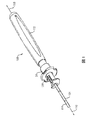
図1および2は、例えば、半月板修復手順において、単純かつ直感的に使用できる、本開示の軟組織修復装置100の第一の実施形態を示す。装置100は、ハンドル102およびハンドル102に連結された針104を含む。ハンドル102は、プラスチック、および金属製の針104から構成されることが好ましい。ハンドル102は、縦軸106を有する本体を含み、針104が組織部位に挿入され得る深さを制限するための調節可能な深さ停止部108を含み得る。深さ停止部108の軸方向位置は、針104からのインプラントの配置の役割を果たす、移動可能要素の軸方向の動きの範囲が深さ停止部108によって制限されるように、ハンドル102に対して調節可能に固定され得る。ハンドルの本体は、インプラントを制御可能に配置するための線形位置決めラチェットアセンブリ112のハウジング部分の溝110を画定し得る。針104は、ハンドル本体の溝110内から延在し、針の長さを延ばす軸方向の穴116を画定する内部表面114を有し得る。
1 and 2 show a first embodiment of the presently disclosed soft
針104は、ラチェットアセンブリ112に延びて連結された近位端118を有し得る。図3に示すように、針104は、遠位インプラント302’を少なくとも部分的に収容する遠位端300(または低プロファイル実施形態302’’)および針の軸方向の穴116の中の近位インプラント304’(または低プロファイル実施形態304’’)を有し得る。近位インプラント304’および遠位インプラント302’は、針の遠位端300から個別にかつ逐次的に配置可能であり、(下記の特定の実施形態では)互いに機械的に連結されていても、いなくてもよく、ノット付きの縫合糸306の長さによって接続される。
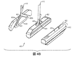
図3は、インプラントの二つの代替的な実施形態、高プロファイルインプラント302’、304’、および低プロファイルインプラント302’’、304’’を示し、それぞれが針104の遠位端300に少なくとも部分的に配置される。針104は、外部表面310から軸方向の穴116および開口遠位端300へ延在するスロット308で構成されてもよく、これは先細で尖った組織穿刺チップ312を形成してもよい。遠位インプラント302および近位インプラント304は、実質的に類似した形状または異なる形状を有し得る。インプラント400の断面、側面および底面斜視図を図4Aに示す。インプラント400は概して、針104内の押し込み嵌めで受けることができるように、軸方向の穴116の断面積にほぼ適合する寸法を有する細長い円筒体402を有し得る。それぞれのインプラントは、針に充填された時、針104の外部表面310を超えて、軸方向の穴116から延在することが意図されているボス404(例えば、突出部、リブ、フィンなど)も有し得、ボス404はスロット308によって摺動可能に受けられる。スロット308による各ボス404の摺動装置は、針104内のインプラント400の放射状アライメントを維持するよう動作する。
FIG. 3 shows two alternative embodiments of the implant, a
各インプラント400は、縫合糸410を通し得る内部縫合経路406で構成され得る。図3は、縫合経路406を形成するボス316内に形成された側部縫合糸交差穴314で構成された高プロファイルインプラント302’、304’の実施形態を示す(図4Aに示される別個の実施形態)。図4Bの代替的実施形態では、内部縫合経路406’は、上部縫合穴408で開始および終了する。これらの構成の両方は有利なことに、縫合糸410の露出した部分がインプラントの配置を妨げず、縫合糸410が誤って切断される危険性を最小限にするために、縫合糸410の必然的に露出した部分(インプラントを接続する部分)を針穴116の外側に配置する。低プロファイル移植302’’、304’’は、組織(例えば、半月板など)部位への外傷を最小限に抑え、手術中に穿刺中の組織との相互作用および針104の除去に起因するインプラント302’’、304’’の不注意による変位を防止するというさらなる利点を提供するために、断面積を減らして構成され得る。図4Aに示すように、インプラント400の「底」側412は(すなわち、穴の開いた面に対して反対側)は、二つのより広い部分418の間の狭い部分416を有する縦の方向の窪み414で構成され得る。狭い部分416は、縫合経路406の「U」字形状の実施形態の底部を形成してもよく、縫合糸410の一部を固定するのに十分嵌合してもよい。
Each
U字形状の縫合経路の代替として、図4Bに示すインプラントの実施形態は、三つの別個のセグメント420a〜420cから構成される縫合経路406’で構成されている。二つのセグメント420a、420bは、インプラント400のボス402のそれぞれの縫合穴408からのインプラント400の本体内で互いに内部に角度をなすように構成され得る。縫合穴408は、縫合穴408の間の狭い部分424を有するボス402内に形成された上部溝422の反対側にあり得る。狭い部分424およびより広い縫合穴408は、縫合糸410が狭い部分424としっかりと適合し、縫合穴408を通って容易に動くように、縫合糸410に対して大きさが決められる。二つのセグメント420a、420bは、インプラント400の底面412の窪み426に形成され得る第三のセグメント420cによって接続される。窪み426は縫合糸410がインプラント400内に実質的に含まれる十分な長さおよび十分な深さを形成する。各縫合経路セグメント420a〜420cは、例えば、縫合糸410の直径よりわずかに大きい直径であるように、縫合糸410に摺動可能に収容するように寸法決めされ、それにより縫合糸のわずかな変形が、縫合糸をインプラント400へ固定するのに十分な機械的抵抗を引き起こし得る。縫合糸410は、セグメント420を通過して、インプラント400内のループを形成することができる。縫合ループをインプラント内に配置することで、外科医が縫合糸の自由端を引くときに、縫合ループが組織と同様にインプラントと針の内壁との間に食い込むことを防ぐ。
As an alternative to a U-shaped suture path, the embodiment of the implant shown in FIG. 4B is comprised of a suture path 406 'comprised of three separate segments 420a-420c. The two
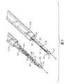
針504からの遠位インプラント500および近位インプラント502の連続的な配置の実施形態の段階が、図5A〜5Cに示されている。図5Aに示すように、両方のインプラント500、502は、最初に針504の軸方向の穴506の中に少なくとも部分的に収容される。高プロファイルインプラントが示されているが、低プロファイルまたは高プロファイルインプラントと低プロファイルインプラントの組み合わせも利用され得ることに留意されたい。配置の最初の段階では、近位インプラント502は、軸方向の穴506を通して並進移動するラチェットアセンブリ112(図示せず)のプッシャー部材508(例えば、フレキシブルロッドまたはチューブなど)によって遠位インプラント500と接触するよう(図5B)に軸方向に付勢され得る。図5Cは、針504の遠位端510が、修復される組織の様々な位置へのアクセスを容易にするための一つまたは複数の平面に湾曲した幾何学的形状を有する代替的実施形態を示す。プッシャー部材508は、この曲がりを収容するように屈曲することができる材料から構成されてもよい。遠位インプラント500が針504から放出された後の近位インプラント502の位置も図5Cに示される。プッシャー部材508は次に、近位インプラント502を針504から押し出してもよく、その後、インプラントを接続する縫合糸を締めてもよい。
Stages of an embodiment of sequential placement of
図6Aおよび6Bに示すように、針602の遠位端600は、遠位インプラント606および/または近位インプラント608のいずれかまたは両方が誤って針602の開口遠位端600から放出または引き出される可能性を最小限にするような適切な寸法で一つ以上の保持機構(例えばくぼみ停止部604)で構成され得る。くぼみ停止部604は、インプラント606、608に加えられた抵抗力がプッシュロッドアクチュエータ610の使用者の動きによって克服され得るように設計される。それぞれのインプラントは、インプラントの寸法を選択して針602の内部表面614内で摺動可能に嵌合することによって、縦方向の穴612内で少なくとも部分的に半径方向の動きに対して軸方向に制約され得る。再び、インプラント606、608は、インプラントボス616および針スロット618による回転運動に対して制約され得る。
As shown in FIGS. 6A and 6B, the
インプラント保持機構は一般に、遠位インプラント606が配置されて近位インプラント608が開口遠位端600の近くの位置に進められた後に、針602の開口遠位端600からより近位に配置されたインプラント608が放出されるなど、インプラントの望ましくない動きに抵抗するように協働するよう対で構成される。図示した実施形態では、くぼみ停止部604は第一の保持機構を備え、インプラント608の本体は第二の保持機構を表す。図6Cに示す別の実施形態では、インプラント626は、針634の内部表面632上に形成された対応する雌受け入れスロット630など、第二の保持機構と相互作用するための雄タブ628などの保持機構で構成され得る。使用者がプッシュロッドアクチュエータ638を介して軸方向の力(矢印636で示す)を適用すると、インプラント626は遠位に移動し、雄タブ628は雌受け入れスロット630に位置する。インプラント626は、保持機構によって生成される抵抗力を克服するために、使用者によってプッシュロッドアクチュエータ638を介して小さな追加的な力がかけられるまで固定される。
The implant retention mechanism is generally placed more proximally from the open
追加的な実施形態では、様々な保持機構が可能である。例えば、針602の開口遠位端600は、代替的に、内部表面632にへこまされるか、または捲縮され、軸方向の穴612内に突き出る保持機構を提供してもよい。第一の保持図は、任意のボスまたはボス受け入れ機構を備えてもよく、内部表面632上の協働保持機構は、対応する嵌合形状を有してもよく、インプラント626上に形成された保持機構は、その側面上および/またはインプラントの遠位または近位端上に形成され得る。
In additional embodiments, various retention mechanisms are possible. For example, the open
他の実施形態では、図6D〜6Fに示すように、第一の保持図は、インプラント642の近位端640上に形成されてもよく、一方対応する嵌合保持図は、プッシュロッドアクチュエータ646の遠位端644上に形成される。図示された様々な実施形態では、連動する保持機構は、くぼみ648、フックおよびロック650、および嵌合可能な角度をなす表面652を含むインターフェースで構成される。
In other embodiments, as shown in FIGS. 6D-6F, the first retention diagram may be formed on the
さらに別の実施形態では、上述の第一および第二の連動する保持機構のいずれかは、端と端に配置される遠位インプラントの近位端および近位インプラントの遠位端に形成され得る。相互接続結合部は、インプラントが針602の開口遠位端600を通って放出されるように、回転ヒンジとして作用するように構成されてもよく、針の穴の内壁によってもはや制約されないインプラントの遠位端は、軸方向に回転し、組織部位でのインプラントの配置において有用であり得る。単一の縫合の上にある三つ以上のインプラントが利用され得ることが容易に理解されるであろう。
In yet another embodiment, any of the first and second interlocking retention mechanisms described above can be formed at the proximal end of the distal implant disposed end to end and the distal end of the proximal implant. . The interconnect joint may be configured to act as a rotating hinge so that the implant is ejected through the open
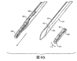
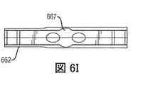
図6G〜6Jに示す実施形態では、針スロット654は、互いに向かって内側に湾曲することができるスロット654の対向する縁部658、660にアワーグラス型保持領域656を含んでもよく、遠位インプラント664が展開された後に近位インプラント662の遠位の(および回転する)動きに抵抗する力を提供する量だけ、縁部間の距離を狭める。遠位インプラント664を配置することにより、近位インプラント662を「アワーグラス」領域656に移動する。遠位インプラント664が配置された後、針666を半月板から除去するときに、近位インプラント662が針666から引き抜かれるのを防止するため、その引抜力が近位インプラント662を遠位に移動するのに十分大きい場合に、さらなる干渉を提供するために、近位インプラント662はその中心667または近位端668で追加的な材料を用いて構成される。さらなる干渉は引抜力を制圧する。各インプラント662、664は、円筒形の本体部分670と、遠位端674から近位端668に実質的に延在するリブ様のボス機構672とを含む。各インプラント662、664のリブ様のボス機構672は、針スロット654内に位置する。
In the embodiment shown in FIGS. 6G-6J, the
好ましい実施形態では、アワーグラス保持領域656は、インプラント662、664のリブ様のボス機構672の幅w2より狭い幅W1を有する。リブ様のボス機構672は、均一な幅を有し得る。しかしながら、一実施形態では、近位インプラント662は、厚さが変化し、インプラント662とアワーグラス保持領域656の間の追加的な圧縮力を生成する、リブ様のボス機構672を有する。図6Jに示すように、近位インプラント662は、遠位端674に沿って均一な幅を有し、インプラント662の中間スパンを超えて延在するリブ様のボス機構672を有し、次にインプラント662の近位端668での厚さが徐々に増加する。さらなるリブ様のボス機構の幅の位置は、遠位インプラント664が展開された後の近位インプラント662の配置位置と一致する。針が半月板から除去される間、近位インプラントが針から放出されないようにするために、追加的な圧縮力が望ましい時にこの位置にある。針とインプラントの間の追加的な圧縮力は、インプラントの意図しない遠位移動を防ぐことを目的としている。
In a preferred embodiment, the hourglass holding region 656 has a width W1 that is narrower than the width w2 of the rib-
図2を再び参照すると、線形位置決めラチェットアセンブリ112は、針軸方向の穴116を通して徐々に引き出され、または格納され、その遠位端で近位インプラント(図示せず)に連結されるように構成されるプッシュロッドアクチュエータ120を含んでもよい。
Referring again to FIG. 2, the linear
図7Aおよび7Bは、回転可能な実質的に環状のラチェット部材700および線形位置決めラチェットアセンブリ702の実施形態を示す。ラチェット部材700は、アクチュエータ706の近位端704に連結されてもよい。ラチェット部材700は、ばね710によって近位方向(矢印708で示す)で付勢され得る。線形位置決めラチェットアセンブリ702はまた、ユーザーノブ(図8Aにおいてノブ800として示される)を含む軸方向に移動可能なプランジャー駆動機構712を含んでもよく、使用者によって直線的に前進したとき(矢印716によって示される方向に)、図7Bのプランジャー駆動機構702の拡大図に示されるように、ラチェット部材700は、ハンドル溝722内の内壁720に形成された離間した歯718と交互に係合および離脱する。ラチェット部材700に近接した先細の歯724は、駆動機構712の対向する遠位に配向された先細の歯726と動作可能に連結される。ラチェット歯724および駆動機構の歯726のそれぞれのセットは、摺動を促進するための類似したピッチ角度および傾斜角を有してもよいが、一連の歯は、初期位置において、かつアーム730(または指、羽根など)の各再配置において、連続する歯718のガレット732内のラチェット部材700をオフセットするように構成され、駆動機構712の遠位に前進すると、ラチェット部材700にかかる回転駆動力を生み出す。駆動機構の先細の歯726のセットは、ノブ800を含む単一の一体的に形成された構成要素、および装置ハンドル734内のスリップ嵌めの一部とし得る。
FIGS. 7A and 7B show an embodiment of a rotatable substantially
ラチェット部材700は、ラチェット部材700の本体の少なくとも一部に沿って軸方向に配置された、一つ以上の半径方向延長アーム730(またはリブ、または類似の特徴など)を用いて構成されてもよく、またハンドル734内の内壁720内に形成された歯718’、718’’と係合するように構成されてもよい。一実施形態では、内壁720は、ハンドルと固定して配置された同軸スプラインチューブ736の内部表面を含み(図2にその全体を示す)。一方で、別の実施形態では、内壁720は、ハンドルの内部の溝の壁を含んでもよい。内壁の歯718’、718’’を接続する軸方向に整列された溝738またはスプラインは、ラチェットアーム730がインプラントの配置中に遠位に移動し得る経路を提供する。両方の(および他の)実施態様では、プランジャー駆動機構712は自由に直線的に動き、ラチェット部材700と係合する。内壁の歯718、718’は、駆動機構712がラチェット部材700を溝またはスプライン経路738に沿って遠位に押す間、ラチェット部材700の回転を防ぐ。しかしながら、ラチェットアーム730が歯718を除去すると、ラチェット部材700は、対向するラチェット先細の歯724と駆動機構先細の歯726との間のオフセット嵌めから生じる回転付勢力、およびばね710によって加えられた近位バイアスに応じて、次のより遠位の内壁の歯718’にある固定位置(例えば、歯ガレット732)の中へ回転する(矢印740で示される方向)。ラチェットアーム730による内壁の歯718、718’の摺動および除去は、それぞれ遠位インプラントまたは近位インプラントの配置に対応する遠位位置で起こるように設計されている。一つ以上の停止部742も、第一の展開段階の間に近位インプラントが誤って配置されないように、ラチェット部材700の前進を所望の遠位前進位置へ制限し得る。歯のガレット732へのラチェット部材の回転およびバネ付勢された再配置は、対応するインプラントが配置された触覚的、および/または聴覚的表示(例えば、スナップなど)を使用者に提供するよう設計され得る。代替的に、プッシャーアクチュエータ706の適切な前進に応答したクリッカー機能(図示せず)は、この表示を使用者に提供し得る。
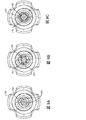
図8A〜8Cおよび図9A〜9Cは、インプラント配置の明確な段階で、組織修復装置802の斜視図および軸方向図を示す。線形位置決めラチェットアセンブリ804およびラチェット部材806の初期状態が図8Aおよび9Aに示される。使用者は、プランジャー駆動機構808を直線的に線形的に(矢印716で示す)遠位に進めて、駆動機構の先細の歯810をアクチュエータ812と回転可能に接続され得るラチェット部材806と係合させる。プッシュ部材(図示せず)の遠位先端は直線的に引き出され、遠位インプラントを配置する。ラチェット部材アーム816と半径方向に整列している個別の止め具814は、遠位インプラントの配置中にアクチュエータ812が過度に前進するのを防止する。
8A-8C and 9A-9C show perspective and axial views of the
プランジャー駆動機構808は、バイアスばねによって付勢されている近位インプラントを配置するために、最初の開始位置に近接して格納してもよい。図8Bおよび9Bは、ラチェット部材806’のより遠位位置、およびより遠位の内壁歯818’で今回転されたアーム816’を示す。次に、近位インプラントは、プランジャー駆動機構800を再度遠位に前進させることによって配置されてもよく、結合されたアクチュエータ812を遠位に引き出し、従って近位インプラントを遠位に動かし、針の先端から近位インプラントを放出する。図8Cおよび9Cは、近位インプラントの配置後、別のより遠位の内壁歯818’’におけるラチェット部材アーム816’’のより遠位で回転した位置を示す。第二の(または最終的な)インプラントが配置されると、ラチェット部材806をさらに回転し、その初期開始溝と再整列させ(すなわち、360度の回転を完了した)、または開始溝の近位端と整列する近位端を有する別の溝の中に回転させることができる。次に、ばねバイアスは、ラチェット部材806を付勢してその開始位置(図8Aに示すような)に戻すか、または開始位置と整列させるようにする。これにより、インプラントの再充填および装置の再使用、ならびに製造後および使用前の装置機能の試験が可能になり得る。
図10A〜10Dを参照すると、本開示の実施形態による組織修復装置1001は、損傷した半月板を修復するなど、最先端の臨床手順で使用され得る。縫合糸1006を使用して連結された二つ(またはそれ以上の)インプラント1002、1004は、針1008によって針穴1010およびスロット1012に保持され得る。望ましい半月板修復位置1013にカニューレで到達すると、針1008は半月板1014に突き刺されてもよく、遠位インプラント1002はラチェットアセンブリを使用して配置され得る。図10Cに示されるように、半月板への挿入深さは、深さチューブ1016によって制限され得る。深さチューブ1016は、深さ停止部1018に遠位に取り付けられ得る。深さ停止部1018が調節されるとき、遠位露出した針の長さを長くするか短くして、針が半月板1014へ貫通するのを制限し得る。次に、針1008は半月板1014から引き戻され、組織の裂傷1020の平面を横切って再挿入するために再配置されてもよく(例えば、裂傷1020の反対側または同じ側にあるが、交差している)、半月板1014に突き刺され得る。次に、近位インプラント1004が配置され得る。移植された時、インプラント1002、1004は組織の表面上にある。次に、装置1001を取り外し、縫合糸の自由端を引っぱった時に、インプラント1002、1004の間の距離を近づけるように結んだ縫合糸1022の長さを残し、インプラント間の縫合糸の長さを短くし、次に組織の裂傷を閉じてもよい。次に、縫合糸1022を締めて切断してもよい。以前のインプラントの配置手段には、二つの別個の作動部材が含まれ、それによって、インプラントが連続的に、または第一のインプラントを配置し、その後、格納して第二のインプラントに順次配置する単一の作動部材に配置する。有利なことに、組織修復装置の実施形態は、インプラントを配置するために使用者によってより直感的に動かされ得る単一の作動部材(例えば、プッシュロッドなど)を含み得る。さらに、一実施形態では、組織修復装置は、再度充填することなく複数の対のインプラントを配置するように構成され得る。
Referring to FIGS. 10A-10D, a
本開示の目的で、ハンドル、アクチュエータ、針、フランジまたはノブ付き駆動機構、ラチェット部材、バネ、深さ停止部および直線位置決めラチェットアセンブリ遠位前進停止部は、金属(例えば、ステンレス鋼)および/または非金属生体適合性材料で形成され得る。縫合糸は、ポリマー材料などの当分野で知られる種類の材料で形成されてもよく、吸収可能であってもよく、または吸収可能でなくてもよい。インプラントは、ポリエチレン、アセタール、またはポリプロピレンなどの剛性で生体適合性の材料から作製され得る。別の方法として、インプラントは金属、弾性的に変形可能な材料、または生体吸収性材料から作製され得る。インプラントは単一で射出成形された断片であることが好ましいが、他の方法でも製造され得る。構成要素間の結合は、機械的手段、非毒性接着剤、生体適合性接着剤、接着糊などの接着手段、または当業者に既知の他の手段を介して形成され得る。装置およびその構成要素はすべて、当業者に既知の製造方法によって作製される。 For purposes of this disclosure, the handle, actuator, needle, flange or drive mechanism with a knob, ratchet member, spring, depth stop and linear positioning ratchet assembly distal advance stop may be metal (eg, stainless steel) and / or It can be formed of a non-metallic biocompatible material. The suture may be formed of a type of material known in the art, such as a polymeric material, and may or may not be absorbable. The implant can be made from a rigid, biocompatible material such as polyethylene, acetal, or polypropylene. Alternatively, the implant can be made from a metal, an elastically deformable material, or a bioabsorbable material. The implant is preferably a single injection molded piece, but may be manufactured in other ways. The bond between the components can be formed through mechanical means, non-toxic adhesives, biocompatible adhesives, adhesive means such as adhesive glue, or other means known to those skilled in the art. The device and its components are all made by manufacturing methods known to those skilled in the art.
当業者には、様々な代替的実施形態が容易に理解されるであろう。例えば、組織修復装置は、可変線形変位で設計され、プッシャー部材の剛性を増加/減少してもよい。プランジャーノブを使用するのではなく、代替的なハンドル型の幾何学的形状および針先端の曲がりを使用し、インプラントを能動的に配置してもよい。組織修復装置は、針を使用して配置する必要はなく、また関節鏡下で配置する必要はない。代わりに、外科医は、開放手順の間にアンカーを組織に対して配置することができる。組織修復装置は、半月板の裂傷以外の組織の傷の修復に使用できる。例えば、装置を皮膚、筋肉、および靭帯における裂傷の修復し、また骨などの構造を支持するために組織を再付着するために使用できる。 Various alternative embodiments will be readily apparent to those skilled in the art. For example, the tissue repair device may be designed with a variable linear displacement to increase / decrease the stiffness of the pusher member. Rather than using a plunger knob, an alternative handle-type geometry and needle tip bending may be used to actively place the implant. The tissue repair device need not be placed using a needle and need not be placed arthroscopically. Alternatively, the surgeon can place the anchor relative to the tissue during the opening procedure. The tissue repair device can be used to repair tissue wounds other than meniscal tears. For example, the device can be used to repair lacerations in skin, muscle, and ligaments, and to reattach tissue to support structures such as bone.
本明細書で使用される要素、作用、または指示は、明示的そのように記載されていない限り、重要または必須と解釈されるべきではない。また、本明細書で使用される場合、冠詞「a」および「an」は一つ以上の項目を含むことが意図されており、「一つ以上」と交換可能に使用されてもよい。さらに、本明細書で使用される場合、「セット」という用語は一つ以上の項目を含むことが意図されており、「一つ以上」と交換可能に使用されてもよい。一つの項目のみが意図されている場合、用語「一つの(one)」または類似の言語が使用される。また、本明細書で使用される場合、「有する(has)」、「有する(have)」、「有する(having)」などの用語はオープンエンドの用語であることが意図されている。さらに、「基づく」という語句は、特に明記しない限り、「少なくとも部分的に基づく」を意味することを意図する。 No element, act, or instruction used herein should be construed as critical or essential unless explicitly described as such. Also, as used herein, the articles “a” and “an” are intended to include one or more items and may be used interchangeably with “one or more”. Further, as used herein, the term “set” is intended to include one or more items and may be used interchangeably with “one or more”. Where only one item is intended, the term “one” or similar language is used. Also, as used herein, terms such as “has”, “have”, “having” and the like are intended to be open-ended terms. Further, the phrase “based on” is intended to mean “based at least in part” unless specifically stated otherwise.
本開示の範囲を逸脱することなく、対応する図を参照して上述した例示的実施形態に対して様々な修正を行うことができるので、前述の説明に含まれ、かつ添付図面に示されているすべての事項は、限定的ではなく例示的として解釈されることを意図する。従って本開示の広さおよび範囲は、上記の例示的な実施形態のいずれかによって限定されるべきではなく、本明細書に添付される以下の請求項およびその均等物に従ってのみ定義されるべきである。 Various modifications can be made to the exemplary embodiments described above with reference to corresponding figures without departing from the scope of this disclosure, and thus are included in the foregoing description and shown in the accompanying drawings. All matters are intended to be construed as illustrative rather than limiting. Accordingly, the breadth and scope of the present disclosure should not be limited by any of the above-described exemplary embodiments, but should be defined only in accordance with the following claims and their equivalents appended hereto. is there.
Claims (29)
縦軸を有するハンドルと、
前記ハンドルから延在する軸方向の穴を画定する細長い針であって、前記針が近位端および遠位端を含む、細長い針と、縫合糸によって接続され、前記針の前記軸方向の穴内に少なくとも部分的に配置される第一のインプラントおよび第二のインプラントであって、前記第二のインプラントが前記第一のインプラントの近位に配置される、第一のインプラントおよび第二のインプラントと、
前記針を通して徐々に前進し、所定の順序で前記第一および前記第二のインプラントをそこから付勢するように構成されたプッシャー部材と、前記プッシャー部材に連結された近位に付勢された回転可能なラチェットと、軸方向の力および回転駆動力を提供し、前記ハンドル内の歯面の連続的なより遠位の歯から前記ラチェットを交互に係合かつ解除させるように構成された軸方向に移動可能な駆動機構と、を備える、ラチェット組立体と、を備える、組織修復装置。 A tissue repair device,
A handle having a longitudinal axis;
An elongate needle defining an axial hole extending from the handle, wherein the needle includes a proximal end and a distal end and is connected by a suture and within the axial hole of the needle A first implant and a second implant disposed at least in part, wherein the second implant is disposed proximal to the first implant; and ,
A pusher member configured to progressively advance through the needle and bias the first and second implants therefrom in a predetermined order and a proximally biased member coupled to the pusher member; A rotatable ratchet and an axis configured to provide axial force and rotational driving force to alternately engage and disengage the ratchet from successive more distal teeth of the tooth surface in the handle A ratchet assembly comprising: a drive mechanism movable in a direction;
前記駆動機構が、前記ラチェットを回転可能に付勢するように、前記ラチェットの一つ以上の先細の歯を係合させるために遠位に配向された前記先細の歯で構成される、請求項1に記載の組織修復装置。 The ratchet has a proximal portion composed of one or more proximally oriented teeth;
The drive mechanism comprises the tapered teeth oriented distally to engage one or more tapered teeth of the ratchet to rotatably bias the ratchet. 2. The tissue repair device according to 1.
前記第一のインプラントおよび前記第二のインプラントのうちの少なくとも一つが、前記針の前記軸方向の穴に近似する断面と、前記スロットと嵌合して前記針内の前記インプラントの回転を防止する突出部と有する本体を備える、請求項1に記載の組織修復装置。 The distal end of the needle includes a slot;
At least one of the first implant and the second implant is fitted with the cross-section approximating the axial hole of the needle and the slot to prevent rotation of the implant within the needle. The tissue repair device according to claim 1, comprising a main body having a protrusion.
縦方向の穴、開口遠位端、前記遠位端近くの軸方向スロットを含む針と、
第一のインプラントおよびノット付きの縫合糸によって接続された第二のインプラントであって、前記第一のインプラントが前記第二のインプラントの遠位に位置し、それぞれのインプラントが少なくとも部分的に前記縦方向の穴の中に制約され、前記穴の中にインプラントの回転を制限するように、前記軸方向の針スロットに摺動可能に収容されるようにボスを有するように構成される、第一のインプラントおよび第二のインプラントと、
前記針の前記穴の中で移動可能であるように構成されたプッシャーであって、前記プッシャーが前記第一のインプラントおよび前記第二のインプラントを前記針の前記開口遠位端から逐次的に放出するように構成された、プッシャーと、
前記プッシャーを作動させるための線形位置決め機構と、を備え、
前記第二のインプラントが、前記第一のインプラントが放出された後に、第二の保持機構と協働して前記針の前記遠位端から前記第二のインプラントの放出に抵抗するように構成される第一の保持機構を含む、システム。 A system for repairing the meniscus,
A needle including a longitudinal bore, an open distal end, an axial slot near the distal end;
A second implant connected by a first implant and a knotted suture, wherein the first implant is located distal to the second implant, and each implant is at least partially in the longitudinal direction. A first boss constrained in the directional bore and configured to have a boss slidably received in the axial needle slot to limit rotation of the implant in the bore. An implant and a second implant,
A pusher configured to be movable within the bore of the needle, wherein the pusher sequentially releases the first implant and the second implant from the open distal end of the needle. A pusher, configured to
A linear positioning mechanism for operating the pusher,
The second implant is configured to cooperate with a second retention mechanism to resist release of the second implant from the distal end of the needle after the first implant is released. Including a first retention mechanism.
前記プッシャーは、前記曲がりを収容するために屈曲することができる材料から構成される、請求項16に記載のシステム。 The distal end of the needle has a bend in at least one plane;
The system of claim 16, wherein the pusher is comprised of a material that can be bent to accommodate the bend.
前記第二の保持機構が、前記針の前記遠位端で前記縦方向の穴の内壁上に構成された対応する嵌合可能機構を含む、請求項16に記載のシステム。 The first holding mechanism includes a boss or a boss receiving mechanism;
The system of claim 16, wherein the second retention mechanism includes a corresponding matable mechanism configured on an inner wall of the longitudinal bore at the distal end of the needle.
前記第二の保持機構が、前記縦方向の穴の内壁上に構成された前記突出部に対する障害物を含み、前記プッシャーを前進させることによって適用可能な軸方向の力よりも小さな抵抗力を提供する、請求項16に記載のシステム。 The first retention mechanism comprises a protrusion from a side of the second implant;
The second holding mechanism includes an obstacle to the protrusion configured on the inner wall of the longitudinal hole and provides a resistance force that is less than the axial force that can be applied by advancing the pusher The system of claim 16.
前記第二の保持機構が、前記プッシャーの遠位先端上に構成された対応する連動する機構を備える、請求項16に記載のシステム。 The first holding mechanism includes a boss or a boss receiving mechanism;
The system of claim 16, wherein the second retention mechanism comprises a corresponding interlocking mechanism configured on a distal tip of the pusher.
前記第二のインプラントが、遠位端上に第四の保持機構をさらに備え、また所望の配置前に前記針の前記遠位端から前記第一のインプラントの放出に抵抗するように前記第三の保持機構と連動するように構成される、請求項16に記載のシステム。 The first implant further comprises a third retention mechanism on the proximal end;
The second implant further comprises a fourth retention mechanism on the distal end and the third implant to resist release of the first implant from the distal end of the needle prior to desired placement. The system of claim 16, wherein the system is configured to interface with a holding mechanism of
それぞれが、前記ボスのそれぞれの縫合穴において一方の端部で開始され、第三のセグメントによって接続された、二つの内側の向かい合う角度をなすセグメントを含む縫合経路であって、それぞれのセグメントが縫合糸を摺動可能に収容する、縫合経路を備える、請求項16に記載のシステム。 At least one of the implants is
Each of the suturing paths comprising two inwardly angled segments starting at one end in each stitching hole of the boss and connected by a third segment, each segment being stitched The system of claim 16, comprising a suture path for slidably receiving a thread.
縫合経路の一対の縫合穴を含み、前記縫合糸が幅広い端および穴によって摺動可能に収容され、かつ前記狭い部分の幅が前記縫合糸の一部をロックし得るように、前記穴が間に狭い部分を有する溝の反対側の幅広い端に形成される、請求項28に記載のシステム。 At least one of the first or second implants is
Including a pair of suture holes in the suture path, wherein the holes are interposed so that the suture is slidably received by a wide end and holes, and the width of the narrow portion can lock a portion of the suture. 29. The system of claim 28, wherein the system is formed at a wide end opposite a groove having a narrow portion.
Applications Claiming Priority (5)
| Application Number | Priority Date | Filing Date | Title |
|---|---|---|---|
| US201662413705P | 2016-10-27 | 2016-10-27 | |
| US62/413,705 | 2016-10-27 | ||
| US201762513046P | 2017-05-31 | 2017-05-31 | |
| US62/513,046 | 2017-05-31 | ||
| PCT/US2017/057977 WO2018081045A1 (en) | 2016-10-27 | 2017-10-24 | Tissue repair device |
Publications (2)
| Publication Number | Publication Date |
|---|---|
| JP2019532729A true JP2019532729A (en) | 2019-11-14 |
| JP2019532729A5 JP2019532729A5 (en) | 2020-12-03 |
Family
ID=60263108
Family Applications (1)
| Application Number | Title | Priority Date | Filing Date |
|---|---|---|---|
| JP2019520131A Pending JP2019532729A (en) | 2016-10-27 | 2017-10-24 | Tissue repair device |
Country Status (6)
| Country | Link |
|---|---|
| US (1) | US10772622B2 (en) |
| EP (1) | EP3531930B1 (en) |
| JP (1) | JP2019532729A (en) |
| CN (1) | CN109906055B (en) |
| AU (1) | AU2017350787A1 (en) |
| WO (1) | WO2018081045A1 (en) |
Families Citing this family (15)
| Publication number | Priority date | Publication date | Assignee | Title |
|---|---|---|---|---|
| US11650294B2 (en) | 2018-03-28 | 2023-05-16 | Murata Manufacturing Co., Ltd. | Fabry-pérot element in lidar device |
| AU2019271230A1 (en) * | 2018-05-17 | 2020-11-26 | Smith & Nephew Asia Pacific Pte Limited | Tissue repair device and method |
| EP3738519A1 (en) * | 2019-05-13 | 2020-11-18 | Smith & Nephew, Inc. | Anchor delivery systems |
| EP3738520B1 (en) | 2019-05-16 | 2024-01-24 | Smith & Nephew, Inc. | Tissue repair assembly |
| WO2021150706A1 (en) * | 2020-01-21 | 2021-07-29 | Children's Medical Center Corporation | Tissue fastening |
| JP2023521285A (en) | 2020-04-08 | 2023-05-24 | スミス アンド ネフュー インコーポレイテッド | meniscal repair delivery device |
| US11375991B1 (en) | 2021-04-08 | 2022-07-05 | Integrity Orthopaedics, Inc. | Tensionable and lockable micro suture anchors and anchor arrays for anatomical attachment of soft tissue to bone |
| US11389154B1 (en) | 2021-04-08 | 2022-07-19 | Integrity Orthopaedics, Inc. | Knotless micro suture anchor array for high density anatomical attachment of soft tissue to bone |
| US11375995B1 (en) | 2021-04-08 | 2022-07-05 | Integrity Orthopaedics, Inc. | Locking suture construct for tensioned suture to suture stitches in anchor arrays for attaching soft tissue to bone |
| US11375992B1 (en) | 2021-04-08 | 2022-07-05 | Integrity Orthopaedics, Inc. | Cartridge device for suture anchor and suture management during implantation of a micro suture anchor array |
| US11382613B1 (en) | 2021-04-08 | 2022-07-12 | Integrity Orthopaedics, Inc. | Methods for transtendinous implantation of knotless micro suture anchors and anchor arrays |
| CN114224411A (en) * | 2021-12-17 | 2022-03-25 | 青岛九远医疗科技有限公司 | Meniscus suturing instrument with good stability |
| CN114668437B (en) * | 2022-05-31 | 2022-08-26 | 杭州锐健马斯汀医疗器材有限公司 | Suturing device |
| CN115177314B (en) * | 2022-08-11 | 2023-12-22 | 杭州锐健马斯汀医疗器材有限公司 | Suture device |
| CN116712144B (en) * | 2023-06-09 | 2023-12-22 | 杭州伯柯曼生物科技有限公司 | Suture implant excitation device |
Family Cites Families (28)
| Publication number | Priority date | Publication date | Assignee | Title |
|---|---|---|---|---|
| CA2124651C (en) * | 1993-08-20 | 2004-09-28 | David T. Green | Apparatus and method for applying and adjusting an anchoring device |
| US5507754A (en) * | 1993-08-20 | 1996-04-16 | United States Surgical Corporation | Apparatus and method for applying and adjusting an anchoring device |
| US5772673A (en) | 1996-03-07 | 1998-06-30 | United States Surgical Corporation | Apparatus for applying surgical clips |
| US5928252A (en) | 1997-01-21 | 1999-07-27 | Regen Biologics, Inc. | Device and method for driving a needle and meniscal repair |
| US6228098B1 (en) | 1998-07-10 | 2001-05-08 | General Surgical Innovations, Inc. | Apparatus and method for surgical fastening |
| GB2340199A (en) * | 1998-08-03 | 2000-02-16 | Stanley Works Ltd | Ratchet mechanism |
| US7153312B1 (en) | 1999-12-02 | 2006-12-26 | Smith & Nephew Inc. | Closure device and method for tissue repair |
| US7887551B2 (en) | 1999-12-02 | 2011-02-15 | Smith & Nephew, Inc. | Soft tissue attachment and repair |
| JP4160386B2 (en) * | 2000-11-02 | 2008-10-01 | スミス アンド ネフュー インコーポレーテッド | Tissue repair occlusion device and tissue repair method |
| AU2007200095B2 (en) | 2000-11-02 | 2008-07-17 | Smith & Nephew, Inc. | Closure device and method for tissue repair |
| US7083638B2 (en) | 2001-02-12 | 2006-08-01 | Arthrocare Corporation | Method and apparatus for attaching connective tissues to bone using a knotless suture anchoring device |
| US6972027B2 (en) * | 2002-06-26 | 2005-12-06 | Stryker Endoscopy | Soft tissue repair system |
| US9314235B2 (en) | 2003-02-05 | 2016-04-19 | Smith & Nephew, Inc. | Tissue anchor and insertion tool |
| CA2583247C (en) * | 2004-10-08 | 2013-06-25 | Tyco Healthcare Group Lp | Endoscopic surgical clip applier |
| US8128640B2 (en) | 2005-02-07 | 2012-03-06 | Ivy Sports Medicine LLC | System and method for all-inside suture fixation for implant attachment and soft tissue repair |
| ES2590252T3 (en) | 2005-02-07 | 2016-11-21 | Ivy Sports Medicine, Llc. | System for fixing a completely internal suture for joining an implant and repairing a soft tissue |
| US20080051707A1 (en) * | 2006-08-25 | 2008-02-28 | Phan Christopher U | Apparatus and methods for use of expandable members in surgical applications |
| US7771429B2 (en) * | 2006-08-25 | 2010-08-10 | Warsaw Orthopedic, Inc. | Surgical tool for holding and inserting fasteners |
| US8758366B2 (en) * | 2007-07-09 | 2014-06-24 | Neotract, Inc. | Multi-actuating trigger anchor delivery system |
| US8828052B2 (en) * | 2008-04-02 | 2014-09-09 | Linvatec Corporation | Method and apparatus for meniscal repair |
| US20100023025A1 (en) | 2008-07-25 | 2010-01-28 | Zeiner Mark S | Reloadable laparoscopic fastener deploying device with disposable cartridge for use in a gastric volume reduction procedure |
| CN103705280B (en) * | 2008-11-26 | 2017-11-14 | 史密夫和内修有限公司 | Tissue repair device |
| US8894669B2 (en) | 2009-05-12 | 2014-11-25 | Ethicon, Inc. | Surgical fasteners, applicator instruments, and methods for deploying surgical fasteners |
| DK200970073A (en) * | 2009-07-22 | 2011-01-23 | Coloplast As | Suturing system and assembly |
| US8403945B2 (en) * | 2010-02-25 | 2013-03-26 | Covidien Lp | Articulating endoscopic surgical clip applier |
| WO2015068166A1 (en) | 2013-11-06 | 2015-05-14 | Yehuda Bachar | Apparatus and method for fixating a device to a body tissue |
| JP2017506980A (en) | 2014-03-05 | 2017-03-16 | コアクシス メディカル, インコーポレイテッド | Suture anchoring system and delivery method |
| CN106999182A (en) | 2014-10-15 | 2017-08-01 | 史密夫和内修有限公司 | Anchoring piece/implant configuration device and relative method of tissue repair |
-
2017
- 2017-10-24 JP JP2019520131A patent/JP2019532729A/en active Pending
- 2017-10-24 WO PCT/US2017/057977 patent/WO2018081045A1/en unknown
- 2017-10-24 EP EP17794584.7A patent/EP3531930B1/en active Active
- 2017-10-24 CN CN201780062378.6A patent/CN109906055B/en active Active
- 2017-10-24 AU AU2017350787A patent/AU2017350787A1/en not_active Abandoned
- 2017-10-26 US US15/794,082 patent/US10772622B2/en active Active
Also Published As
| Publication number | Publication date |
|---|---|
| EP3531930A1 (en) | 2019-09-04 |
| US10772622B2 (en) | 2020-09-15 |
| AU2017350787A1 (en) | 2019-05-23 |
| CN109906055B (en) | 2022-05-10 |
| CN109906055A (en) | 2019-06-18 |
| EP3531930B1 (en) | 2021-12-15 |
| US20180116654A1 (en) | 2018-05-03 |
| WO2018081045A1 (en) | 2018-05-03 |
Similar Documents
| Publication | Publication Date | Title |
|---|---|---|
| JP2019532729A (en) | Tissue repair device | |
| CN107440773B (en) | Meniscal repair devices, systems and methods | |
| CA2510080C (en) | Minimally invasive stitching device | |
| JP4190752B2 (en) | Fasteners for fixing hernia mesh | |
| US10390822B2 (en) | Surgical fasteners and methods and devices for deploying a surgical fastener | |
| US20150250470A1 (en) | Suture anchoring system and delivery method | |
| US11864750B2 (en) | Knotless anchor insertion | |
| EP3154446B1 (en) | Apparatus for suturing a tissue | |
| US20220240925A1 (en) | Minimally-invasive tissue suturing device | |
| WO2019014158A1 (en) | Systems, devices and methods for delivering transfascial suture implants for securing surgical mesh to tissue | |
| RU2667609C2 (en) | Surgical fastening elements with hinged connections and tips made with possibility to deflect | |
| WO2023126493A1 (en) | Knotless anchor inserter tool extraction | |
| US20240122592A1 (en) | Knotless anchor insertion | |
| BR112019009685B1 (en) | MINIMALLY INVASIVE DEVICE FOR TISSUE SUTURE |
Legal Events
| Date | Code | Title | Description |
|---|---|---|---|
| RD03 | Notification of appointment of power of attorney |
Free format text: JAPANESE INTERMEDIATE CODE: A7423 Effective date: 20190419 |
|
| RD04 | Notification of resignation of power of attorney |
Free format text: JAPANESE INTERMEDIATE CODE: A7424 Effective date: 20190426 |
|
| A521 | Request for written amendment filed |
Free format text: JAPANESE INTERMEDIATE CODE: A523 Effective date: 20201023 |
|
| A621 | Written request for application examination |
Free format text: JAPANESE INTERMEDIATE CODE: A621 Effective date: 20201023 |
|
| A977 | Report on retrieval |
Free format text: JAPANESE INTERMEDIATE CODE: A971007 Effective date: 20210806 |
|
| A131 | Notification of reasons for refusal |
Free format text: JAPANESE INTERMEDIATE CODE: A131 Effective date: 20210810 |
|
| A02 | Decision of refusal |
Free format text: JAPANESE INTERMEDIATE CODE: A02 Effective date: 20220307 |