JP2019530538A - System and method for defoaming needle assembly - Google Patents
System and method for defoaming needle assembly Download PDFInfo
- Publication number
- JP2019530538A JP2019530538A JP2019520154A JP2019520154A JP2019530538A JP 2019530538 A JP2019530538 A JP 2019530538A JP 2019520154 A JP2019520154 A JP 2019520154A JP 2019520154 A JP2019520154 A JP 2019520154A JP 2019530538 A JP2019530538 A JP 2019530538A
- Authority
- JP
- Japan
- Prior art keywords
- needle
- distal end
- needle assembly
- antifoam
- base
- Prior art date
- Legal status (The legal status is an assumption and is not a legal conclusion. Google has not performed a legal analysis and makes no representation as to the accuracy of the status listed.)
- Pending
Links
- 238000000034 method Methods 0.000 title claims abstract description 35
- 239000007788 liquid Substances 0.000 claims abstract description 63
- 239000002518 antifoaming agent Substances 0.000 claims abstract description 24
- 239000012530 fluid Substances 0.000 claims abstract description 14
- 238000004891 communication Methods 0.000 claims abstract description 11
- 230000003254 anti-foaming effect Effects 0.000 claims abstract description 5
- 238000000605 extraction Methods 0.000 claims description 13
- 150000001875 compounds Chemical class 0.000 claims description 8
- 230000005587 bubbling Effects 0.000 claims description 2
- 239000002131 composite material Substances 0.000 claims description 2
- 238000005187 foaming Methods 0.000 description 18
- 239000003814 drug Substances 0.000 description 17
- 229940079593 drug Drugs 0.000 description 17
- 239000000243 solution Substances 0.000 description 16
- 238000012986 modification Methods 0.000 description 7
- 230000004048 modification Effects 0.000 description 7
- 230000001681 protective effect Effects 0.000 description 4
- 239000007789 gas Substances 0.000 description 3
- 239000007787 solid Substances 0.000 description 3
- 238000001802 infusion Methods 0.000 description 2
- 239000000463 material Substances 0.000 description 2
- 238000005266 casting Methods 0.000 description 1
- 238000010586 diagram Methods 0.000 description 1
- 230000009977 dual effect Effects 0.000 description 1
- 230000000694 effects Effects 0.000 description 1
- 239000006260 foam Substances 0.000 description 1
- 239000011521 glass Substances 0.000 description 1
- 238000002347 injection Methods 0.000 description 1
- 239000007924 injection Substances 0.000 description 1
- 238000001746 injection moulding Methods 0.000 description 1
- 238000004519 manufacturing process Methods 0.000 description 1
- 230000035515 penetration Effects 0.000 description 1
- 239000000843 powder Substances 0.000 description 1
- 238000003860 storage Methods 0.000 description 1
- 238000002560 therapeutic procedure Methods 0.000 description 1
- 239000012815 thermoplastic material Substances 0.000 description 1
- XLYOFNOQVPJJNP-UHFFFAOYSA-N water Substances O XLYOFNOQVPJJNP-UHFFFAOYSA-N 0.000 description 1
Images


Classifications
-
- A—HUMAN NECESSITIES
- A61—MEDICAL OR VETERINARY SCIENCE; HYGIENE
- A61J—CONTAINERS SPECIALLY ADAPTED FOR MEDICAL OR PHARMACEUTICAL PURPOSES; DEVICES OR METHODS SPECIALLY ADAPTED FOR BRINGING PHARMACEUTICAL PRODUCTS INTO PARTICULAR PHYSICAL OR ADMINISTERING FORMS; DEVICES FOR ADMINISTERING FOOD OR MEDICINES ORALLY; BABY COMFORTERS; DEVICES FOR RECEIVING SPITTLE
- A61J1/00—Containers specially adapted for medical or pharmaceutical purposes
- A61J1/14—Details; Accessories therefor
- A61J1/20—Arrangements for transferring or mixing fluids, e.g. from vial to syringe
- A61J1/2003—Accessories used in combination with means for transfer or mixing of fluids, e.g. for activating fluid flow, separating fluids, filtering fluid or venting
- A61J1/2079—Filtering means
- A61J1/2082—Filtering means for gas filtration
-
- A—HUMAN NECESSITIES
- A61—MEDICAL OR VETERINARY SCIENCE; HYGIENE
- A61J—CONTAINERS SPECIALLY ADAPTED FOR MEDICAL OR PHARMACEUTICAL PURPOSES; DEVICES OR METHODS SPECIALLY ADAPTED FOR BRINGING PHARMACEUTICAL PRODUCTS INTO PARTICULAR PHYSICAL OR ADMINISTERING FORMS; DEVICES FOR ADMINISTERING FOOD OR MEDICINES ORALLY; BABY COMFORTERS; DEVICES FOR RECEIVING SPITTLE
- A61J1/00—Containers specially adapted for medical or pharmaceutical purposes
- A61J1/14—Details; Accessories therefor
- A61J1/20—Arrangements for transferring or mixing fluids, e.g. from vial to syringe
- A61J1/2003—Accessories used in combination with means for transfer or mixing of fluids, e.g. for activating fluid flow, separating fluids, filtering fluid or venting
- A61J1/2006—Piercing means
- A61J1/2013—Piercing means having two piercing ends
-
- A—HUMAN NECESSITIES
- A61—MEDICAL OR VETERINARY SCIENCE; HYGIENE
- A61J—CONTAINERS SPECIALLY ADAPTED FOR MEDICAL OR PHARMACEUTICAL PURPOSES; DEVICES OR METHODS SPECIALLY ADAPTED FOR BRINGING PHARMACEUTICAL PRODUCTS INTO PARTICULAR PHYSICAL OR ADMINISTERING FORMS; DEVICES FOR ADMINISTERING FOOD OR MEDICINES ORALLY; BABY COMFORTERS; DEVICES FOR RECEIVING SPITTLE
- A61J1/00—Containers specially adapted for medical or pharmaceutical purposes
- A61J1/14—Details; Accessories therefor
- A61J1/20—Arrangements for transferring or mixing fluids, e.g. from vial to syringe
- A61J1/2003—Accessories used in combination with means for transfer or mixing of fluids, e.g. for activating fluid flow, separating fluids, filtering fluid or venting
- A61J1/202—Separating means
- A61J1/2027—Separating means having frangible parts
-
- A—HUMAN NECESSITIES
- A61—MEDICAL OR VETERINARY SCIENCE; HYGIENE
- A61J—CONTAINERS SPECIALLY ADAPTED FOR MEDICAL OR PHARMACEUTICAL PURPOSES; DEVICES OR METHODS SPECIALLY ADAPTED FOR BRINGING PHARMACEUTICAL PRODUCTS INTO PARTICULAR PHYSICAL OR ADMINISTERING FORMS; DEVICES FOR ADMINISTERING FOOD OR MEDICINES ORALLY; BABY COMFORTERS; DEVICES FOR RECEIVING SPITTLE
- A61J1/00—Containers specially adapted for medical or pharmaceutical purposes
- A61J1/14—Details; Accessories therefor
- A61J1/20—Arrangements for transferring or mixing fluids, e.g. from vial to syringe
- A61J1/2003—Accessories used in combination with means for transfer or mixing of fluids, e.g. for activating fluid flow, separating fluids, filtering fluid or venting
- A61J1/202—Separating means
- A61J1/2037—Separating means having valve means
-
- A—HUMAN NECESSITIES
- A61—MEDICAL OR VETERINARY SCIENCE; HYGIENE
- A61J—CONTAINERS SPECIALLY ADAPTED FOR MEDICAL OR PHARMACEUTICAL PURPOSES; DEVICES OR METHODS SPECIALLY ADAPTED FOR BRINGING PHARMACEUTICAL PRODUCTS INTO PARTICULAR PHYSICAL OR ADMINISTERING FORMS; DEVICES FOR ADMINISTERING FOOD OR MEDICINES ORALLY; BABY COMFORTERS; DEVICES FOR RECEIVING SPITTLE
- A61J1/00—Containers specially adapted for medical or pharmaceutical purposes
- A61J1/14—Details; Accessories therefor
- A61J1/20—Arrangements for transferring or mixing fluids, e.g. from vial to syringe
- A61J1/2003—Accessories used in combination with means for transfer or mixing of fluids, e.g. for activating fluid flow, separating fluids, filtering fluid or venting
- A61J1/2048—Connecting means
- A61J1/2058—Connecting means having multiple connecting ports
-
- A—HUMAN NECESSITIES
- A61—MEDICAL OR VETERINARY SCIENCE; HYGIENE
- A61J—CONTAINERS SPECIALLY ADAPTED FOR MEDICAL OR PHARMACEUTICAL PURPOSES; DEVICES OR METHODS SPECIALLY ADAPTED FOR BRINGING PHARMACEUTICAL PRODUCTS INTO PARTICULAR PHYSICAL OR ADMINISTERING FORMS; DEVICES FOR ADMINISTERING FOOD OR MEDICINES ORALLY; BABY COMFORTERS; DEVICES FOR RECEIVING SPITTLE
- A61J1/00—Containers specially adapted for medical or pharmaceutical purposes
- A61J1/14—Details; Accessories therefor
- A61J1/20—Arrangements for transferring or mixing fluids, e.g. from vial to syringe
- A61J1/2003—Accessories used in combination with means for transfer or mixing of fluids, e.g. for activating fluid flow, separating fluids, filtering fluid or venting
- A61J1/2068—Venting means
- A61J1/2075—Venting means for external venting
-
- A—HUMAN NECESSITIES
- A61—MEDICAL OR VETERINARY SCIENCE; HYGIENE
- A61J—CONTAINERS SPECIALLY ADAPTED FOR MEDICAL OR PHARMACEUTICAL PURPOSES; DEVICES OR METHODS SPECIALLY ADAPTED FOR BRINGING PHARMACEUTICAL PRODUCTS INTO PARTICULAR PHYSICAL OR ADMINISTERING FORMS; DEVICES FOR ADMINISTERING FOOD OR MEDICINES ORALLY; BABY COMFORTERS; DEVICES FOR RECEIVING SPITTLE
- A61J1/00—Containers specially adapted for medical or pharmaceutical purposes
- A61J1/14—Details; Accessories therefor
- A61J1/20—Arrangements for transferring or mixing fluids, e.g. from vial to syringe
- A61J1/2096—Combination of a vial and a syringe for transferring or mixing their contents
-
- A—HUMAN NECESSITIES
- A61—MEDICAL OR VETERINARY SCIENCE; HYGIENE
- A61M—DEVICES FOR INTRODUCING MEDIA INTO, OR ONTO, THE BODY; DEVICES FOR TRANSDUCING BODY MEDIA OR FOR TAKING MEDIA FROM THE BODY; DEVICES FOR PRODUCING OR ENDING SLEEP OR STUPOR
- A61M5/00—Devices for bringing media into the body in a subcutaneous, intra-vascular or intramuscular way; Accessories therefor, e.g. filling or cleaning devices, arm-rests
- A61M5/178—Syringes
- A61M5/31—Details
- A61M5/32—Needles; Details of needles pertaining to their connection with syringe or hub; Accessories for bringing the needle into, or holding the needle on, the body; Devices for protection of needles
- A61M5/3295—Multiple needle devices, e.g. a plurality of needles arranged coaxially or in parallel
- A61M5/3298—Needles arranged in parallel
-
- A—HUMAN NECESSITIES
- A61—MEDICAL OR VETERINARY SCIENCE; HYGIENE
- A61M—DEVICES FOR INTRODUCING MEDIA INTO, OR ONTO, THE BODY; DEVICES FOR TRANSDUCING BODY MEDIA OR FOR TAKING MEDIA FROM THE BODY; DEVICES FOR PRODUCING OR ENDING SLEEP OR STUPOR
- A61M5/00—Devices for bringing media into the body in a subcutaneous, intra-vascular or intramuscular way; Accessories therefor, e.g. filling or cleaning devices, arm-rests
- A61M5/178—Syringes
- A61M5/31—Details
- A61M5/32—Needles; Details of needles pertaining to their connection with syringe or hub; Accessories for bringing the needle into, or holding the needle on, the body; Devices for protection of needles
- A61M5/34—Constructions for connecting the needle, e.g. to syringe nozzle or needle hub
- A61M5/344—Constructions for connecting the needle, e.g. to syringe nozzle or needle hub using additional parts, e.g. clamping rings or collets
- A61M5/345—Adaptors positioned between needle hub and syringe nozzle
-
- A—HUMAN NECESSITIES
- A61—MEDICAL OR VETERINARY SCIENCE; HYGIENE
- A61M—DEVICES FOR INTRODUCING MEDIA INTO, OR ONTO, THE BODY; DEVICES FOR TRANSDUCING BODY MEDIA OR FOR TAKING MEDIA FROM THE BODY; DEVICES FOR PRODUCING OR ENDING SLEEP OR STUPOR
- A61M5/00—Devices for bringing media into the body in a subcutaneous, intra-vascular or intramuscular way; Accessories therefor, e.g. filling or cleaning devices, arm-rests
- A61M5/178—Syringes
- A61M5/31—Details
- A61M5/32—Needles; Details of needles pertaining to their connection with syringe or hub; Accessories for bringing the needle into, or holding the needle on, the body; Devices for protection of needles
- A61M5/34—Constructions for connecting the needle, e.g. to syringe nozzle or needle hub
- A61M5/347—Constructions for connecting the needle, e.g. to syringe nozzle or needle hub rotatable, e.g. bayonet or screw
-
- A—HUMAN NECESSITIES
- A61—MEDICAL OR VETERINARY SCIENCE; HYGIENE
- A61M—DEVICES FOR INTRODUCING MEDIA INTO, OR ONTO, THE BODY; DEVICES FOR TRANSDUCING BODY MEDIA OR FOR TAKING MEDIA FROM THE BODY; DEVICES FOR PRODUCING OR ENDING SLEEP OR STUPOR
- A61M5/00—Devices for bringing media into the body in a subcutaneous, intra-vascular or intramuscular way; Accessories therefor, e.g. filling or cleaning devices, arm-rests
- A61M5/36—Devices for bringing media into the body in a subcutaneous, intra-vascular or intramuscular way; Accessories therefor, e.g. filling or cleaning devices, arm-rests with means for eliminating or preventing injection or infusion of air into body
- A61M5/38—Devices for bringing media into the body in a subcutaneous, intra-vascular or intramuscular way; Accessories therefor, e.g. filling or cleaning devices, arm-rests with means for eliminating or preventing injection or infusion of air into body using hydrophilic or hydrophobic filters
- A61M5/385—Devices for bringing media into the body in a subcutaneous, intra-vascular or intramuscular way; Accessories therefor, e.g. filling or cleaning devices, arm-rests with means for eliminating or preventing injection or infusion of air into body using hydrophilic or hydrophobic filters using hydrophobic filters
-
- A—HUMAN NECESSITIES
- A61—MEDICAL OR VETERINARY SCIENCE; HYGIENE
- A61M—DEVICES FOR INTRODUCING MEDIA INTO, OR ONTO, THE BODY; DEVICES FOR TRANSDUCING BODY MEDIA OR FOR TAKING MEDIA FROM THE BODY; DEVICES FOR PRODUCING OR ENDING SLEEP OR STUPOR
- A61M5/00—Devices for bringing media into the body in a subcutaneous, intra-vascular or intramuscular way; Accessories therefor, e.g. filling or cleaning devices, arm-rests
- A61M5/178—Syringes
- A61M5/31—Details
- A61M2005/3123—Details having air entrapping or venting means, e.g. purging channels in pistons
Abstract
【解決手段】 底部とそれに対向するチャンバとを有する容器から液体を抜き出すときに泡を回避するための消泡ニードルアセンブリのためのシステムおよび方法が提供される。より具体的には、消泡ニードルアセンブリは、ニードル基部を有し、ニードル基部は、第1の端部と、その反対側の第2の端部と、それらの間の側壁と、を備え、第2の端部は、バレルとプランジャとを有するシリンジに一時的に接続するように構成および配置されており、第1のニードルは、中空シャフトと、第1の端部から延びて第1の端部の上方で開いた遠位端を提供する第1の長さとを有し、第1のニードルは、側壁を通って通気された第2の端部を有し、第2のニードルは、中空シャフトと、反転したときに、第1の端部の上方、かつ第1のニードルの遠位端の下方の遠位端を提供するために、第1のニードルとほぼ平行に第1の端部から延びる第2の長さを有し、第2のニードルは、ニードル基部の第2の端部と流体連通する第2の端部を有する。関連する使用方法もまた提供される。【選択図】図1ASystems and methods are provided for an antifoaming needle assembly for avoiding bubbles when withdrawing liquid from a container having a bottom and an opposing chamber. More specifically, the antifoam needle assembly has a needle base, the needle base comprising a first end, an opposite second end, and a sidewall therebetween. The second end is configured and arranged to temporarily connect to a syringe having a barrel and a plunger, and the first needle extends from the hollow shaft and the first end to the first end. A first length providing a distal end open above the end, the first needle has a second end vented through the sidewall, and the second needle is A first end substantially parallel to the first needle to provide a hollow shaft and, when inverted, a distal end above the first end and below the distal end of the first needle. A second length extending from the second portion, wherein the second needle is in fluid communication with the second end of the needle base. Having end. Related uses are also provided. [Selection] Figure 1A
Description
本発明は、概して、バイアルからシリンジまで液体を抽出するための装置に関し、液体を通して気泡として生じる一般的な発泡を回避する。泡は注射器内に容易に引き込まれないので泡立ちは非常に望ましくなく、したがってバイアル内で取得できないままで残っている液体の少なくともいくらかの損失をもたらし、高価で無駄な問題である。 The present invention relates generally to an apparatus for extracting liquid from a vial to a syringe, avoiding the general foaming that occurs as bubbles through the liquid. Foaming is highly undesirable because it is not easily drawn into the syringe, thus leading to at least some loss of liquid that remains unacquired in the vial, an expensive and wasteful problem.
いくつかの用途では事前装填された注射器が使用されているが、事前に計量されたバイアルで薬が提供されることがはるかに一般的である。典型的には、バイアルは無菌容器であり、一般的にはガラス製であり、ニードルを抜き取るために通過を許容しながら、安全にその中に薬液を収容するように作用する貫通可能かつ再シール可能な栓を有する。 Although some applications use pre-loaded syringes, it is much more common for drugs to be provided in pre-metered vials. Typically, the vial is a sterile container, typically made of glass, that is pierceable and resealable that acts to safely contain the medicinal solution therein while allowing the needle to pass through. Has a possible plug.
バイアル内の薬剤は典型的には2つの形態のうちの1つで提供され、第1は抽出の準備ができている液体薬剤溶液としてである。輸送費、重さ、そして潜在的に薬の寿命のために、第二の形態は粉末のように乾燥しており、薬液を提供するために計量された量の水または他の液体をバイアルに注入することによって再構成される。 The drug in the vial is typically provided in one of two forms, the first being as a liquid drug solution ready for extraction. Due to transportation costs, weight, and potentially drug life, the second form is dry like a powder, and a metered amount of water or other liquid is placed in a vial to provide a drug solution. Reconstituted by injection.
どちらの方法でも、同じ発泡の問題が発生する可能性がある。バイアルは所望の液体を含みシールされているので、シリンジを装填する一般的な方法は、ゴム栓を通してシリンジのニードルを導き、次にシリンジのプランジャを引き戻してシリンジの室内に吸引力を生じさせ、それに応じてニードルを通して液体を吸引する。 Both methods can cause the same foaming problem. Because the vial contains and is sealed with the desired liquid, a common method of loading the syringe is to guide the syringe needle through a rubber stopper and then pull the syringe plunger back to create a suction force in the syringe chamber, Accordingly, liquid is sucked through the needle.
液体がシリンジ内に引き込まれるにつれて、シリンジ内の圧力で低下し、ニードルの周りで空気がバイアル内に吸い込まれる。さらに、ゴムシールはニードルの周囲から液体が漏れるのを防ぐのに十分であるが、ゴム栓の圧力差及び可撓性の性質により空気が吸い込まれる。 As the liquid is drawn into the syringe, the pressure in the syringe drops and air is drawn into the vial around the needle. In addition, the rubber seal is sufficient to prevent liquid from leaking around the needle, but air is inhaled due to the pressure difference and the flexible nature of the rubber stopper.
バイアルは典型的には抽出中にひっくり返されるので、ゴムシールはバイアルの最下点にある。したがって、ニードルの周囲でバイアルに入る空気は、バイアル内の液体を通って浸透しなければならず、したがって泡立ちおよび発泡の問題を引き起こす。より多くの液体が抽出されるにつれて、より多くの空気が吸い込まれ、より多くの発泡が起こり得る。 Since the vial is typically turned over during extraction, the rubber seal is at the lowest point of the vial. Thus, air entering the vial around the needle must penetrate through the liquid in the vial, thus causing foaming and foaming problems. As more liquid is extracted, more air is inhaled and more foaming can occur.
いくつかの場合において、ニードルとゴムシールとの間のシールは、空気が入らないほどきついが、空気を導入しなければ、ユーザが所望の量の薬液を引き出すことはほとんど不可能であることに留意すべきである。 Note that in some cases, the seal between the needle and the rubber seal is so tight that no air enters, but it is almost impossible for the user to withdraw the desired amount of drug solution without introducing air. Should.
もちろん、推奨される選択肢の1つは、バイアルから引き出す薬液の量と等しい量の空気をシリンジに引き込み、ニードルをストッパに挿入し、バイアルを裏返してバイアルに空気を注入し、薬液を引き出すことである。これは典型的な最終使用者の患者にとって、実用的ではない。バイアルに注入する空気が多すぎると、薬液がニードルの周囲に押し出される可能性がある。空気が薬液を通して注入され、その上に注入されていない場合は、再び泡立ちと発泡が起こる可能性がある。 Of course, one of the recommended options is to draw an amount of air equal to the amount of drug solution to be withdrawn from the vial into the syringe, insert the needle into the stopper, turn the vial over, inject air into the vial, and pull out the drug solution. is there. This is not practical for typical end-user patients. If too much air is injected into the vial, the drug solution may be pushed out around the needle. If air is injected through the drug solution but not over it, foaming and foaming can occur again.
薬が注入治療用で、バイアル全体が1回の治療に使用される可能性が高い場合は、このプロセスを何度も繰り返す必要があり、各繰り返しプロセスで、発泡と潜在的な損失という同じ問題が発生する。さらに、空気注入と吸引の繰り返しは、注射器内の薬液に気泡を追加する可能性が最も高く、これもまた望ましくない。 If the drug is for infusion therapy and the entire vial is likely to be used for a single treatment, this process must be repeated many times, with the same problem of foaming and potential loss with each iteration process Will occur. Further, repeated air infusion and aspiration is most likely to add bubbles to the drug solution in the syringe, which is also undesirable.
抽出プロセス中にバイアルへの空気の導入を容易にするために、Braun Medical Inc.によりMini-Spike(登録商標)として知られる装置が開発されている。一般に、これらの装置は本質的に通気ニードルとして機能する構造であり、その例は、サイドポート付きのベント型ニードルと題されたRainsの米国特許第4,787,878号である。より具体的には、Rainsは、互いに直角をなす2つのポートを有する本体を教示しており、一方は液体を通すためのものであり、他方は空気を通すためのものである。これらのポートはそれぞれニードル先で終端しており、連続的な傾斜した端部構造を提供する。空気用のポートは液体用のポートよりわずかに上にあるが、高さの違いはそれほど重要ではない。 A device known as Mini-Spike® has been developed by Braun Medical Inc. to facilitate the introduction of air into the vial during the extraction process. In general, these devices are designed to function essentially as vent needles, an example of which is Rains US Pat. No. 4,787,878 entitled Bent Needle with Side Ports. More specifically, Rains teaches a body having two ports at right angles to each other, one for passing liquid and the other for passing air. Each of these ports terminates at the needle tip, providing a continuous slanted end structure. The air port is slightly above the liquid port, but the height difference is less important.
薬液の抽出中にバイアル内に空気を導入することは効果的であるが、空気ポートと流体ポートは効果的に互いに隣接し、抽出中に薬液内にあるので、空気ポートによってもたらされる改善された空気流は、薬液中に直接空気を供給し、通気孔のないニードルの周りに浸透している空気よりもさらに大きな泡立ちと泡立ちをもたらす結果となる。 While it is effective to introduce air into the vial during the extraction of the medicinal solution, the air port and the fluid port are effectively adjacent to each other and are in the medicinal solution during the extraction, resulting in an improved air port The air flow provides air directly into the drug solution, resulting in greater foaming and foaming than air permeating around a needle without a vent.
Scislowiczの以前の参考文献である米国特許第3,938,520号もまた2つのポートを提供しており、この場合はピアスチップの側面にある。参考文献Rainsと同様に、Scislowicz装置は空気ポートと液体ポートとを互いに実質的に隣り合わせに配置しているので、バイアルからの抽出中は両方とも液体内に配置される。したがって、より現代的なRains装置と同様に、Scislowicz装置も抽出プロセス中に泡立ちと発泡を生じさせるのに非常に効果的である。 Scislowicz's previous reference, US Pat. No. 3,938,520, also provides two ports, in this case on the side of the piercing tip. Similar to the reference Rains, the Scislowicz device places the air port and the liquid port substantially next to each other so that both are placed in the liquid during extraction from the vial. Therefore, as with the more modern Rains device, the Scislowicz device is very effective in producing foaming and foaming during the extraction process.
さらに、Scislowicz、Rains、Mini-Spike(登録商標)、または一般的なスタイルの同等品であるかどうかにかかわらず、これらのタイプのベントニードルでは、抽出時に空気供給ポイントが薬液自体の中にあるため、バイアル内の泡の発生を許容する。 In addition, these types of vent needles, whether they are Scislowicz, Rains, Mini-Spike (R), or a common style equivalent, have an air supply point in the drug solution itself during extraction Therefore, generation | occurrence | production of the bubble in a vial is permitted.
したがって、上記で特定された課題のうちの1つまたは複数を克服することができる、バイアルから薬液を取り除くことができる消泡ニードルアセンブリのための方法およびシステムが必要とされている。 Accordingly, there is a need for a method and system for an antifoaming needle assembly that can remove a drug solution from a vial that can overcome one or more of the problems identified above.
本発明は、消泡ニードルアセンブリのための新規なシステムおよび方法を提供することによって従来技術の問題を解決する。 The present invention solves the problems of the prior art by providing a novel system and method for an antifoam needle assembly.
特に、一例として、本発明の一実施形態によれば、液体を収容するのに適した中空容器から液体を抜き出すときに泡が発生するのを回避する方法であって、容器は、底部と、反対側に、貫通可能かつ再シール可能な栓でシールされている開口部とを有するチャンバを有し、栓は、チャンバの上に内面を形成し、方法は、中空シャフトを有する第1のニードルを貫通可能かつ再シール可能なストッパを通して挿入し、第1のニードルの遠位端をチャンバの底部に隣接して配置し、第1のニードルの第2の端はチャンバの外側で開いたままであり、中空シャフトを有する第2のニードルを貫通可能かつ再シール可能なストッパを通して挿入して第2のニードルの遠位端を内面に隣接して配置し、第2のニードルの第2の端を、プランジャ付きバレルを有するシリンジに接続し、容器を反転させ、第1のニードルの遠位端を、チャンバの最上部の内面に隣接して配置し、プランジャを作動させて液体を容器から第2のニードルを通してシリンジのバレルの中に引き込み、第1のニードルは、抽出中の液体の泡立ちを最小限に抑えるために分配される液体の上の容器に空気を送ることを可能にする。 In particular, by way of example, according to one embodiment of the present invention, a method for avoiding the generation of bubbles when extracting liquid from a hollow container suitable for containing liquid, the container comprising: On the opposite side, has a chamber having an opening that is sealed with a penetrable and resealable plug, the plug forming an inner surface over the chamber, and the method includes a first needle having a hollow shaft Through the pierceable and resealable stopper, the distal end of the first needle is positioned adjacent to the bottom of the chamber, and the second end of the first needle remains open outside the chamber A second needle having a hollow shaft is inserted through the penetrable and resealable stopper to place the distal end of the second needle adjacent the inner surface, and the second end of the second needle is Barre with plunger The syringe is connected, the container is inverted, the distal end of the first needle is positioned adjacent to the top inner surface of the chamber, and the plunger is activated to allow liquid to flow from the container through the second needle The first needle allows air to be delivered to the container above the dispensed liquid to minimize liquid bubbling during extraction.
異なる実施形態では、液体を収容するのに適した中空容器から液体を抜き出すときに泡が発生するのを回避する消泡ニードルアセンブリであって、容器は、底部と、反対側に、貫通可能かつ再シール可能な栓でシールされている開口部とを有するチャンバを有し、栓は、チャンバの上に内面を形成し、消泡ニードルアセンブリは、ニードル基部を有し、ニードル基部は、第1の端部と、その反対側の第2の端部と、それらの間の側壁と、を備え、第2の端部は、バレルとプランジャとを有するシリンジに一時的に接続するように構成および配置されており、第1のニードルは、中空シャフトと、第1の端部から延びて第1の端部の上方で開いた遠位端を提供する第1の長さとを有し、第1のニードルは、側壁を通って通気された第2の端部を有し、第2のニードルは、中空シャフトと、反転したときに、第1の端部の上方、かつ第1のニードルの遠位端の下方の遠位端を提供するために、第1のニードルとほぼ平行に第1の端部から延びる第2の長さを有し、第2のニードルは、ニードル基部の第2の端部と流体連通する第2の端部を有する。 In a different embodiment, an antifoaming needle assembly that avoids the generation of bubbles when withdrawing liquid from a hollow container suitable for containing liquid, the container being penetrable on the bottom and opposite side, and And a chamber having an opening sealed with a resealable plug, the plug forming an inner surface over the chamber, the antifoam needle assembly has a needle base, and the needle base has a first And a second end opposite thereto and a sidewall therebetween, the second end configured to temporarily connect to a syringe having a barrel and a plunger and A first needle having a hollow shaft and a first length extending from the first end and providing an open distal end above the first end; The needle has a second end vented through the side wall. And the second needle is provided with a hollow shaft and, when inverted, to provide a distal end above the first end and below the distal end of the first needle. And a second length extending from the first end substantially parallel to the second end, the second needle having a second end in fluid communication with the second end of the needle base.
更なる実施形態によれば、液体を収容するのに適した中空容器から液体を抜き出すときに泡が発生するのを回避する消泡ニードルアセンブリであって、容器は、底部と、反対側に、貫通可能かつ再シール可能な栓でシールされている開口部とを有するチャンバを有し、栓は、チャンバの上に内面を形成し、消泡ニードルアセンブリは、ニードル基部を有し、ニードル基部は、第1の端部と、その反対側の第2の端部と、それらの間の側壁と、を備え、第2の端部は、バレルとプランジャとを有するシリンジに一時的に接続するように構成および配置されており、第1の複合ニードル組立体は、基部の第1の端部から基部の上方の遠位端まで延びる中空シャフトを有し、シャフトは、第1及び第2の流体チャネルを囲み、第1のチャネルは、ニードル基部の側壁に配置された通気口と流体連通し、シャフトの遠位端の少なくとも1つの開口で終端し、第2のチャネルは、ニードル基部の第2の端部と流体連通し、シャフトに沿った、遠位端の直前の少なくとも1つの第2の開口で終端する。 According to a further embodiment, an antifoaming needle assembly that avoids foaming when extracting liquid from a hollow container suitable for containing liquid, the container being on the bottom and on the opposite side, And an opening sealed with a penetrable and resealable plug, the plug forming an inner surface above the chamber, the defoaming needle assembly has a needle base, the needle base is A first end, an opposite second end, and a sidewall therebetween, the second end temporarily connecting to a syringe having a barrel and a plunger. The first compound needle assembly has a hollow shaft extending from a first end of the base to a distal end above the base, the shaft comprising first and second fluids Surround the channel, the first channel Fluid communication with a vent located in the sidewall of the dollar base and terminates in at least one opening at the distal end of the shaft, and the second channel is in fluid communication with the second end of the needle base and communicates with the shaft. Terminates in at least one second opening along the distal end just before the distal end.
詳細な説明に進む前に、本教示は例示のみを目的としており、限定を目的としていないことを理解されたい。本明細書における概念は、消泡ニードルアセンブリのための特定のシステムまたは方法による使用または適用に限定されない。したがって、本明細書に記載の手段は例示的な実施形態に関して示し説明した説明の便宜のためであるが、本明細書の原理は消泡ニードルアセンブリ、及び薬液を発泡させずに薬液をバイアルから取り出す方法を含む他の種類のシステムおよび方法にも同様に適用できることが理解されよう。 Before proceeding to the detailed description, it is to be understood that the present teachings are for illustrative purposes only and are not intended to be limiting. The concepts herein are not limited to use or application by a particular system or method for an antifoam needle assembly. Thus, while the means described herein are for the convenience of the description shown and described with respect to the exemplary embodiments, the principles herein are that the defoaming needle assembly and the drug solution from the vial without foaming the drug solution. It will be appreciated that other types of systems and methods, including methods of retrieval, are equally applicable.
本発明は、図面を参照して以下の説明において好ましい実施形態に関して説明され、図面において、同じ番号は同じまたは類似の要素を表す。さらに、同じまたは類似の要素の番号付けに関して、先行する値はその要素が最初に識別され説明される図を識別し、例えば、要素100は図1に最初に現れることを理解すべきである。
The present invention is described in terms of preferred embodiments in the following description with reference to the drawings, in which like numbers represent the same or similar elements. Further, with respect to the numbering of the same or similar elements, it should be understood that the preceding value identifies the figure in which the element is first identified and described, for example,
図1を参照し、より具体的には注釈付き図面図1A、図1B、及び図1Cには、本発明の様々な実施形態による消泡ニードルアセンブリ、以下AFNA100の3つの変形例が示されている。以下にさらに説明するように、一般に、AFNA100は、共通の基部106から平行に延びる第1のニードル102及び第2のニードル104を含む。基部106は、第1の端部108と第2の端部110とそれらの間の側壁112とを有する。第1のニードル102は、基部106内の通気口114に連結されている。第2のニードル104は、シリンジに連結されるように構成および配置されている基部106の第2の端部110と流体連通している。
Referring to FIG. 1, and more particularly to the annotated drawings FIGS. 1A, 1B, and 1C, three variations of an antifoam needle assembly, hereinafter AFNA 100, according to various embodiments of the present invention are shown. Yes. As described further below, the AFNA 100 generally includes a
左から始まり、図1Aは、2つの明確に別々のニードル、第1のニードル102A及び第2のニードル104Aを有する、AFNA100Aの変形例1である。真ん中の図1Bは、一方の側に沿って互いに隣接して配置された2つのニードル、すなわち第1のニードル102B及び第2のニードル104Bを有する、AFNA100Bの変形例2を示す。最も右側の図1Cは、2つのニードルを一緒にスリーブ付けしたAFNA100Cの変形例3を示し、第2のニードル104Cは第1のニードル102Cの周りにスリーブ付けされている。
Starting from the left, FIG. 1A is
このAFNA100のためのシステムおよび方法の説明を容易にするために、図に示されるAFNA100の向きは、図1に示されるように互いに直交する3つの軸を有する座標系を基準としている。軸は、AFNA100の中心となるように選択された座標系の原点で互いに交差するが、全ての図に示された軸は、明瞭さと説明を容易にするためにそれらの実際の位置からずれている。
To facilitate the description of the system and method for this
各変形例1、2及び3について、AFNA100の基部106は第1の端部108を有し、その反対側には第2の端部110及び端部間の側壁112がある。第2の端部110は、バレルとプランジャを有するシリンジに一時的に接続するように構成され配置されている(図4Aおよび図4B参照)。さらに、少なくとも一実施形態では、第2の端部110はルアーコネクタである。
For each
示されるように、ニードルはすべて基部の第1の端部108から延びる。さらに、変形例1 100A、変形例2 100B、及び 変形例3 100Cでは、第1及び第2のニードル、それぞれ102A/104A、102B/104B、及び102C/104Cも同様に互いにほぼ平行であることが理解されよう。さらに、図1AのAFNA100Aのような少なくとも1つの実施形態については、当然のことながら、第1のニードル102A及び第2のニードル104Aは、実際、基部106Aから延びる別個の構造である。さらに、第1のニードル102Aと第2のニードル104Aとの間には、それらが基部106から離れる方向に延びるにつれて物理的な空間がある。
As shown, all of the needles extend from the
図1BのAFNA100B又は図1CのAFNA100Cのような少なくとも1つの代替実施形態については、第1のニードル102C/B及び第2のニードル104C/Bは、複合構造として一体化されていない場合には、少なくとも部分的に互いに側面接触している。
For at least one alternative embodiment, such as AFNA 100B in FIG. 1B or AFNA 100C in FIG. 1C, if
第1のニードル102は、中空シャフトを有し、基部106の第1の端部108から延びてそれに近接する少なくとも1つの開口部114を有する遠位端118を提供するように第1の長さL1 116を有する。第1のニードル102が中空であるので、第2の端部は通気口、例えばベース106の側壁112内の通気口114を通じて通気される。さらに別の実施形態では、通気口114を基部106の第1の端部108、さらには第2の端部110に配置することができるが、側壁112に配置される少なくとも1つの実施形態では製造が簡単であり、さらに後述するように、第1のニードル102を基部106内にさらに押し戻してもよい実施形態を容易にすることができる。
The
少なくとも一実施形態では、第1のニードル102には、通気孔114内にフィルタを配置することなどによって、エアフィルタが装着される。さらに、少なくとも1つの実施形態では、第1のニードル102は一方向弁によってゲート制御され、空気が通気口114通過して通気口114内に入り込み、したがって空気流路の遠位端118の少なくとも1つの開口部114から出ることができるが、空気又は液体は第1のニードル102を通過してからは通気口114から出ることはできない。
In at least one embodiment, the
第2のニードル104も同様に、基部106の第1の端部108から延び、第1のニードル102とほぼ平行に延びる中空シャフト及び第2の長さL2 122を有し、反転時には、遠位端124が基部106の上方に、かつ第1のニードル102の遠位端118の下方にくる。第2のニードル104の遠位端124に近接して少なくとも1つの開口部126がある。
Similarly, the
さらに別の実施形態では、AFNA100は、図1Cの変形例3 100Cと同様に、二重チャネル構造からその長さの約4分の1から3分の1、又は半分までテーパーする、より完全に統合された複合ニードルとして提供されてもよく、複合ニードル128構造の第1のニードル102部分の液体チャネルの1つ又はそれ以上の遠位開口の真上に、第1のニードル102だけと同等のニードル構造に、液体用の内部チャネルと同様に第2のニードル104及び第1のニードル102の空気流路を提供する。そのような複合ニードル128構造は、それが効果的に1つの尖った先端のみを有するので、いくつかの実施形態において望ましいかもしれない。
In yet another embodiment,
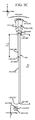
図4から明らかなように、図1および変形例1 100A、変形例2 100B、及び変形例3 100Cの図面では、第1のニードル102の長さ、例えばL1 116は、第2のニードル104の長さ、例えばL2 122よりかなり長い。その重要な要素は、第1のニードル102の遠位端118と第2のニードル104の遠位端124との間の相対的な差、より具体的には第1のニードルの遠位端に近接する開口部120と第2のニードル104の遠位端124に近接する開口部126間の相対的な差である。
As is apparent from FIG. 4, in the drawings of FIG. 1 and
さらに、所与の液体バイアルについて、バイアルチャンバの内側底部と再シール可能な栓の内側表面との間に内部寸法がある。第1の長さと第2の長さとの間の相対的な差は、第1のニードル102の遠位端116をバイアルチャンバの底部に最も近く配置し、第2のニードル104の遠位端124もバイアル内に、かつ再シール可能な栓の内面に近接して配置するように予め選択される。
Further, for a given liquid vial, there is an internal dimension between the inner bottom of the vial chamber and the inner surface of the resealable stopper. The relative difference between the first and second lengths places the
このような構成により、シリンジに固定された実施形態のAFNA100が再シール可能な栓を通して導かれると、第1のニードル102の遠位端116はチャンバの底部および第2のニードル104の遠位端124は、再シール可能な栓の内面に近接する。次にバイアル反転されると、液体は第2のニードル104の遠位端124の近く及び真上にあり、第1のニードル102の遠位端116は液体の上にあり、したがって空気または他の気泡内、かつバイアル内にある。
With such a configuration, when the
プランジャが後方に引っ張られてシリンジのチャンバ内に吸引力が生じると、空気は第1のニードル102の遠位端116に近接した開口部120からバイアル内に通過するが、遠位端116に近接する開口部120は、液体から出ている(例えば、それがバイアル内のエアポケット内の液体の上にある)ので、発泡は起こらない。
When the plunger is pulled rearward to create a suction force in the syringe chamber, air passes through the opening 120 proximate the
さらに、添付の図面を参照して以下でさらに説明されるように、第1のニードル102は、バイアルから液体を出す第2のニードル104の遠位端124の開口部126のかなり上の点でバイアル内への空気の通過を容易にすることを目的とする。
Further, as further described below with reference to the accompanying drawings, the
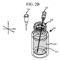
これは、例示的なバイアル200を示す図2Aからより理解され、2つの別々のニードルは、第1のニードル102及び第2のニードル104を表す。理解されるように、バイアル200はチャンバ202とチャンバ202内の液体204とを有する。直立しているとき、液体204の上にエアギャップまたはエアポケット206がある。液体104をより容易に理解できるように、バイアル200がちょうど動かされたかのように、液体204が上部にわずかな波を伴って示されている。「空気」は、厳密には呼吸可能な空気に対する限定ではなく、この空間内のガスを指すことが理解され認識され、通常の空気、消毒された空気、他のガスまたはガスの組み合わせであってもよい。
This is better understood from FIG. 2A showing an
再シール可能な栓208がバイアル200に固定されており、これはバイアル200にニードルを挿入することを可能にし、これはバイアル200から液体204を引き出すための伝統的な方法である。やはり示されているように、チャンバ202の底部212と再シール可能な栓208の内面214との間に寸法D 210がある。
A
示されるように、第1のニードル102及び第2のニードル104は、それらの間の長さの差が事実上寸法D´216となるようにそれらの基部を整列させる。様々な実施形態では、D´216はD 210と等しいかそれよりわずかに小さい。さらに、少なくとも1つの実施形態では、D´216はD 210の少なくとも50%である。さらにまた、少なくとも1つの実施形態では、D´216はD 210の少なくとも80%である。さらに、少なくとも1つの実施形態では、D´216は、D 210とD 210の25%の間にあるように選択される。
As shown, the
図2Bに示すように、第1のニードル102は再シール可能な栓208を通じて挿入されており、第1のニードル102の遠位端118はチャンバ212の底部212上に載っている。対照的に、バイアル200の隣に配置された第2のニードル104は、図3A及び3Bに示すように、再シール可能な栓208を通して導かれたときに、部分的にチャンバ202内に延びているだけである。
As shown in FIG. 2B, the
図3Aでは、第1のニードル102が挿入されたバイアル200は、シリンジ300内にチャンバ302を画定するために協働して作用するバレル306及びプランジャ304を有するシリンジ300に固定された第2のニードル104の上に反転して配置される。バイアル200が反転されているので、第1のニードル102の遠位端118は、チャンバ202の底部212に隣接しているので、第1のニードル102の遠位端118がバイアル200のチャンバ202内のエアポケット206内にあることは明らかである。
In FIG. 3A, the
次いで、バイアル200と第2のニードル104は、図3Bに示されるように一緒にされる。ここで、第2のニードル104の遠位端124は、再シール可能な栓208の内面214に近接していると理解される。このように、プランジャ304が引き込まれると、空気が第1のニードル102を通ってチャンバ202内の液体204よりはるか上にあるリリースポイントまで、バイアル200のチャンバ202内に移動する際に、液体204が第2のニードル104を通ってシリンジ300のチャンバ306内に引き込まれる。そのように、液体204を通る気泡がなく、発泡は有利に回避される。
The
発泡の問題を回避するために確かに効果的であるが、2つの別々の異なるニードル、例えば別々の第1のニードル102及び別々の第2のニードルの使用は、すべての状況において理想的ではないかもしれない。したがって、AFNA100の様々な実施形態は、使用者が両方のニードルを保護する必要なく、どちらのニードルをシリンジに取り付けるべきか、そしてどちらのニードルを取り付けないのかを区別し、第2のニードル104の適切な配置を可能にするために、最初のニードルの向きを操作することなく2つの異なるニードルの消泡効果をもたらす。
While certainly effective to avoid foaming problems, the use of two separate different needles, such as separate
図4A及び図4Bは、図1Aに示す変形例1 100Aに対応するAFNA100の一実施形態を示す。図4A及び図4Bに示すように、AFNA100はシリンジ300に取り付けられている。図3A及び図3Bに示す2つのニードルを用いたプロセスとは有利な対照的に、ここで操作者は1つのアセンブリおよびバイアル200を操作することのみを要求される。
4A and 4B show an embodiment of the
さらに、シリンジ300に取り付けられると、操作者は、握れる固くて大きな対象物を有し、したがって、再シール可能なストッパ208を通して第1のニードル102を向け、次に再シール可能なストッパ208を通して第2のニードル104を着座させるという、より容易な経験を享受し得る。より具体的には、ここで、基部106の第1の端部108が再シール可能な栓208に遭遇し、第1のニードル102又は第2のニードル104のいずれかのバイアル200内へのさらなる動作が効果的に防止される。
In addition, when attached to the
少なくとも一実施形態では、第2のニードル104の長さは、再シール可能なストッパ208を貫通し、第2のニードル104の遠位端124を再シール可能なストッパ208の内面214に近接して配置するのに十分であるように予め選択される。少なくとも一実施形態では、基部106は、オペレータが第1端部108を再シール可能なストッパ208の外面に当接させることによってAFNA100の適切な配置を確認できるように、ほぼ平坦な第1端部108を有する。
In at least one embodiment, the length of the
図によって示唆されているように、第1のニードル102は、第2のニードル104より細いゲージニードルであり、その主な機能は、外部から再シール可能な栓208及び液体204を通して、バイアル200が図示のように反転しているときにバイアル200内の液体204の上方の位置まで空気の通過である。さらに、様々な実施形態では、第1のニードル102は、チャンバ202の底部212に遭遇すると、または遭遇したときに曲がるように、少なくとも部分的に可撓性であり得る。
As suggested by the figure, the
少なくとも一実施形態では、第1のニードル102の長さL1 116は、チャンバ202の底部212と接触するのに十分である。少なくとも1つの代替実施形態では、第1のニードル102の長さL1 116は、図2のD 210として示される内部寸法よりも短くなるように選択される。その結果、第1のニードル102の遠位端118はチャンバ202の底部212に近接するが必ずしも接触しない。
In at least one embodiment, the
さらに別の実施形態では、第1のニードル102が取り付けられている基部106は、AFNA100が再シール可能な栓208を通して第2のニードル104を着座させるように係合し、第1のニードル102がチャンバ202の底部212と接触した場合に、第1のニードル102が基部106内に滑り込むことを可能にする。
In yet another embodiment, the base 106 to which the
さらに別の実施形態では、第1のニードル102は、ぴったりと嵌合するように互いに滑り嵌めされている少なくとも2つの部分を含む伸縮構造である。やはり、ぴったりと嵌合することは、再シール可能なストッパ208の抵抗を克服するのに十分であり得るが、第1のニードル102の遠位端118がチャンバ202の底部212と接触する場合、セクションは余分な長さL1 116を占めて一緒にスライドし、第2のニードル104が再シール可能なストッパ208を通って着座することを可能にする。
In yet another embodiment, the
さらに他の実施形態では、伸縮構造は、最初は圧縮された収納位置にあってもよい。伸縮構造が再シール可能なストッパ208を通って挿入されるとき、それは収納位置から長さL1 116に向かって延ばされてもよい。やはり、伸縮構造は、チャンバ202の底部212に到達するよりも短くなるように構成され配置されてもよく、あるいはチャンバ202の底部212からの抵抗に遭遇すると、同心要素はさらなる拡張を停止してもよい。
In still other embodiments, the telescopic structure may initially be in a compressed storage position. When the telescopic structure is inserted through the
図1B(AFNA 100B)及び図1C(AFNA 100C)に示すAFNA100の変形例のような、ニードル構造が複合ニードル構造である実施形態では、第1のニードル102は、第2のニードル104とほぼ同じ長さで圧縮状態に保持されてもよい。これは、第1のニードル102と第2のニードル104の両方の上に配置された保護カバーによって少なくとも部分的に達成され得る。そのような実施形態では、第1のニードル102は、カバーを貫通しないように鋭利でなくてもよい。しかしながら、カバーを被せられたAFNA100が再シール可能な栓208に対して配置されるとき、第2のニードル104は鋭利であり、カバーが基部106に向かって圧縮するにつれて、第1のニードル102及び第2のニードル104が保護カバーおよび再シール可能なストッパ208を通過する。ここで、無制限に、第1のニードル102は長さL1 116に向かって伸縮自在に拡張することができる。
In embodiments where the needle structure is a compound needle structure, such as a variation of
加えて、遠位端116は、ニードルで典型的であるように角度を付けて示されているが、遠位端116は、中実端のすぐ後ろに配置された、穴またはスリットなどの開口部120を有する中実または閉点であり得る。
In addition, although the
さらに、様々な実施形態では、第1のニードル102の第1の長さL1 116は、第2のニードル104の第2の長さL2 122の少なくとも1.5倍である。実際、少なくとも一実施形態では、第1のニードル102の第1の長さL1 116は、第2のニードル104の第2の長さL2 122の少なくとも2倍である。
Further, in various embodiments, the
図5A、図5B及び図5Cは、図1Aに示すAFNA100のベース106を示す拡大図の注釈である。このような基部106は、第1の端部108、第2の端部110、及び第1の端部108と第2の端部110との間の側壁112を形成するように熱可塑性材料の射出成形又は注型によって作製され得る。基部106は、成形又は彫り込まれた材料のほぼ中実の部分であり得るので、第2のニードル104から基部106を通って第2の端部110への液体通路、及び通気口120から第1の端部への空気通路を提供するポート/チャネルを除いて、側壁112は実際には単にベース106を構成する側部材料として見ることができる。これらの拡大図が示すのに役立つように、少なくとも1つの実施形態では、第1のニードル102は、サイドベント120に接続されているスリーブ500内に配置されている。第2のニードル104は、ルアーコネクタ504としても示されている第2の端部110に接続されているスリーブ502内に配置されている。
5A, 5B and 5C are enlarged view annotations showing the
上述のように、少なくとも一実施形態では、第1のニードル102の遠位端118がチャンバ202の底部212に遭遇すると、第1のニードル102を基部106内に押し戻すことができる。これは、第1のニードル102を、スリーブ500を受け入れる第1のニードル102内に部分的にのみ取り付けることによって達成することができる。そのような実施形態では、チャンバ202の底部212に遭遇した場合、第1のニードル102はさらにベント120に向かってベース106内に押し込まれる。やはり理解され得るように、AFNA100のこの実施形態のための通気口120のサイズは、フィルタ、一方向弁、またはその両方が通気口120内に配置され得るようなものである。
As described above, in at least one embodiment, when the
図1A、図1B及び図1Cに戻ると、少なくとも1つの実施形態では、取り外し可能な保護キャップ(図示せず)が第1のニードル102および第2のニードル104を保護的に覆うために設けられている。図1A、図1B及び図1Cに示されるAFNA100の実施形態に関して、それぞれの端面図が示されている。様々な実施形態では、保護キャップは、ベース106の周りにスナップ嵌合する伝統的なスタイル、または2016年10月12日に出願され、参照により本明細書に組み込まれる、「人間工学的ニードルのためのシステムおよび方法」という名称の米国特許出願第15/291,913に記載の人間工学的ニードル保護装置であり得る。
Returning to FIGS. 1A, 1B, and 1C, in at least one embodiment, a removable protective cap (not shown) is provided to protectively cover the
さらに要約すると、少なくとも1つの実施形態について、液体204の収容に適したバイアル200などの中空容器から液体204を抽出するときに泡の発生を回避するためのAFNA100が提供され、容器は、底部212およびその反対側に、貫通可能かつ再シール可能な栓208でシールされた開口部がチャンバ202の上方に内面214を形成する。このAFNA100は、第1の端部108と、その反対側の第2の端部110と、それらの間の側壁112とを有するニードルベース106を含む。第2の端部110は、バレル302、プランジャ304、及び内部チャンバ306を有するシリンジ300に一時的に接続するように構成および配置されている。中空シャフト及び第1の長さL1 116を有する第1のニードル102は、第1の端部108から延びて第1の端部108の上方に開いた遠位端118を提供し、第1のニードル102は側壁112を通って通気される第2の端部を有する。第2のニードル104が、第1のニードル102とほぼ平行に第1の端部108から延在する中空シャフトと第2の長さL2 122を有し、第2のニードル104は、ニードル基部106の第2の端部110と流体連通する第2の端部を有する。前述のように、第1の長さL1 116は第1のニードル102の遠位端118をチャンバ202の底部212に近接して配置するように予め選択され、第2の長さL2 122は第2のニードル104の遠位端124をチャンバ202内、かつ再シール可能な栓208に近接して配置するように予め選択される。
To further summarize, for at least one embodiment, an
さらに別の実施形態は、液体の封じ込めに適した中空容器から液体204を抽出するときに泡の発生を回避するためのAFNA100であって、容器は、底部212及びそれとは反対側に、チャンバ202の上方に内面214を提供する貫通可能で再シール可能なストッパ208でシールされた開口を有するチャンバ202を有するものとして要約することができる。このAFNA100は、第1の端部108と、その反対側の第2の端部110と、それらの間の側壁112とを有するニードルベース106を含む。第2の端部110は、バレル302とプランジャ304とを有するシリンジ300に一時的に接続するように構成され配置されている。中空シャフト及び第1の長さL1 116を有する第1のニードル102が第1の端部108から延びて第1の端部108の上方に開いた遠位端118を提供する。中空シャフト及び第1のニードル102の第1の長さL1 116の少なくとも半分の第2の長さL2 122を有する第2のニードル104が、第1の端部108から、第1のニードル102とほぼ平行に延び、第1の端部108の上方、かつ第1のニードル102の遠位端118の下に遠位端124を提供し、第2のニードルは、ニードルベース106の第2の端部110と流体連通する第2の端部110を有する。
Yet another embodiment is an
本発明の範囲から逸脱することなく、上記の方法、システム、及び構造に変更を加えることができる。したがって、上記の説明に含まれている及び/又は添付の図面に示されている事項は、例示として解釈されるべきであり、限定的な意味ではないことに留意されたい。実際、当業者には明らかであるように、他の多くの実施形態が実行可能かつ可能である。添付の特許請求の範囲は、本明細書で論じられた実施形態によって、またはその実施形態によって限定されず、それらの用語および均等論によってのみ限定される。 Changes may be made in the above methods, systems, and structures without departing from the scope of the invention. Accordingly, it should be noted that the matter contained in the above description and / or shown in the accompanying drawings is to be construed as illustrative and not restrictive. In fact, many other embodiments are feasible and possible, as will be apparent to those skilled in the art. The scope of the appended claims is not limited by or by the embodiments discussed herein, but only by their terms and equivalents.
Claims (41)
容器は、底部と、反対側に、貫通可能かつ再シール可能な栓でシールされている開口部とを有するチャンバを有し、栓は、チャンバの上に内面を形成し、
方法は、
中空シャフトを有する第1のニードルを貫通可能かつ再シール可能なストッパを通して挿入し、第1のニードルの遠位端をチャンバの底部に隣接して配置し、第1のニードルの第2の端はチャンバの外側で開いたままであり、
中空シャフトを有する第2のニードルを貫通可能かつ再シール可能なストッパを通して挿入して第2のニードルの遠位端を内面に隣接して配置し、第2のニードルの第2の端を、プランジャ付きバレルを有するシリンジに接続し、
容器を反転させ、第1のニードルの遠位端を、チャンバの最上部の内面に隣接して配置し、
プランジャを作動させて液体を容器から第2のニードルを通してシリンジのバレルの中に引き込み、第1のニードルは、抽出中の液体の泡立ちを最小限に抑えるために分配される液体の上の容器に空気を送ることを可能にする、方法。 A method for avoiding the generation of bubbles when extracting liquid from a hollow container suitable for containing liquid,
The container has a chamber having a bottom and, on the opposite side, an opening sealed with a penetrable and resealable stopper, the stopper forms an inner surface above the chamber;
The method is
A first needle having a hollow shaft is inserted through a penetrable and resealable stopper, the distal end of the first needle is positioned adjacent to the bottom of the chamber, and the second end of the first needle is Remain open outside the chamber,
A second needle having a hollow shaft is inserted through a penetrable and resealable stopper to position the distal end of the second needle adjacent to the inner surface and the second end of the second needle is a plunger. Connected to a syringe with a barrel with
Invert the container and place the distal end of the first needle adjacent the top inner surface of the chamber;
Actuate the plunger to draw liquid from the container through the second needle into the barrel of the syringe and the first needle is in the container above the liquid to be dispensed to minimize liquid bubbling during extraction. A method that allows you to send air.
消泡ニードルアセンブリは、
ニードル基部を有し、ニードル基部は、
第1の端部と、その反対側の第2の端部と、それらの間の側壁と、を備え、第2の端部は、バレルとプランジャとを有するシリンジに一時的に接続するように構成および配置されており、
第1のニードルは、中空シャフトと、第1の端部から延びて第1の端部の上方で開いた遠位端を提供する第1の長さとを有し、第1のニードルは、側壁を通って通気された第2の端部を有し、
第2のニードルは、中空シャフトと、反転したときに、第1の端部の上方、かつ第1のニードルの遠位端の下方の遠位端を提供するために、第1のニードルとほぼ平行に第1の端部から延びる第2の長さを有し、第2のニードルは、ニードル基部の第2の端部と流体連通する第2の端部を有する、
請求項1に記載の方法。 The method is performed using an antifoam needle assembly,
The defoaming needle assembly
Having a needle base,
A first end, a second end opposite the first end, and a sidewall therebetween, the second end temporarily connecting to a syringe having a barrel and a plunger. Configured and arranged,
The first needle has a hollow shaft and a first length extending from the first end and providing a distal end open above the first end, the first needle having a side wall. A second end vented through,
The second needle is substantially the same as the first needle to provide a hollow shaft and, when inverted, a distal end above the first end and below the distal end of the first needle. A second length extending in parallel from the first end, the second needle having a second end in fluid communication with the second end of the needle base;
The method of claim 1.
容器は、底部と、反対側に、貫通可能かつ再シール可能な栓でシールされている開口部とを有するチャンバを有し、栓は、チャンバの上に内面を形成し、
消泡ニードルアセンブリは、
ニードル基部を有し、ニードル基部は、
第1の端部と、その反対側の第2の端部と、それらの間の側壁と、を備え、第2の端部は、バレルとプランジャとを有するシリンジに一時的に接続するように構成および配置されており、
第1のニードルは、中空シャフトと、第1の端部から延びて第1の端部の上方で開いた遠位端を提供する第1の長さとを有し、第1のニードルは、側壁を通って通気された第2の端部を有し、
第2のニードルは、中空シャフトと、反転したときに、第1の端部の上方、かつ第1のニードルの遠位端の下方の遠位端を提供するために、第1のニードルとほぼ平行に第1の端部から延びる第2の長さを有し、第2のニードルは、ニードル基部の第2の端部と流体連通する第2の端部を有する、
消泡ニードルアセンブリ。 A defoaming needle assembly that avoids the generation of bubbles when withdrawing liquid from a hollow container suitable for containing liquid,
The container has a chamber having a bottom and, on the opposite side, an opening sealed with a penetrable and resealable stopper, the stopper forms an inner surface above the chamber;
The defoaming needle assembly
Having a needle base,
A first end, a second end opposite the first end, and a sidewall therebetween, the second end temporarily connecting to a syringe having a barrel and a plunger. Configured and arranged,
The first needle has a hollow shaft and a first length extending from the first end and providing a distal end open above the first end, the first needle having a side wall. A second end vented through,
The second needle is substantially the same as the first needle to provide a hollow shaft and, when inverted, a distal end above the first end and below the distal end of the first needle. A second length extending in parallel from the first end, the second needle having a second end in fluid communication with the second end of the needle base;
Antifoam needle assembly.
容器は、底部と、反対側に、貫通可能かつ再シール可能な栓でシールされている開口部とを有するチャンバを有し、栓は、チャンバの上に内面を形成し、
消泡ニードルアセンブリは、
ニードル基部を有し、ニードル基部は、
第1の端部と、その反対側の第2の端部と、それらの間の側壁と、を備え、第2の端部は、バレルとプランジャとを有するシリンジに一時的に接続するように構成および配置されており、
第1の複合ニードル組立体は、基部の第1の端部から基部の上方の遠位端まで延びる中空シャフトを有し、シャフトは、第1及び第2の流体チャネルを囲み、
第1のチャネルは、ニードル基部の側壁に配置された通気口と流体連通し、シャフトの遠位端の少なくとも1つの開口で終端し、
第2のチャネルは、ニードル基部の第2の端部と流体連通し、シャフトに沿った、遠位端の直前の少なくとも1つの第2の開口で終端する、消泡ニードルアセンブリ。 A defoaming needle assembly that avoids the generation of bubbles when withdrawing liquid from a hollow container suitable for containing liquid,
The container has a chamber having a bottom and, on the opposite side, an opening sealed with a penetrable and resealable stopper, the stopper forms an inner surface above the chamber;
The defoaming needle assembly
Having a needle base,
A first end, a second end opposite the first end, and a sidewall therebetween, the second end temporarily connecting to a syringe having a barrel and a plunger. Configured and arranged,
The first compound needle assembly has a hollow shaft extending from a first end of the base to a distal end above the base, the shaft enclosing the first and second fluid channels;
The first channel is in fluid communication with a vent located in the side wall of the needle base and terminates in at least one opening at the distal end of the shaft;
The defoaming needle assembly, wherein the second channel is in fluid communication with the second end of the needle base and terminates in at least one second opening along the shaft just before the distal end.
Applications Claiming Priority (5)
| Application Number | Priority Date | Filing Date | Title |
|---|---|---|---|
| US201662407950P | 2016-10-13 | 2016-10-13 | |
| US62/407,950 | 2016-10-13 | ||
| US15/729,916 US10993877B2 (en) | 2016-10-13 | 2017-10-11 | System and method for anti-foaming needle assembly |
| PCT/US2017/056210 WO2018071588A1 (en) | 2016-10-13 | 2017-10-11 | System and method for anti-foaming needle assembly |
| US15/729,916 | 2017-10-11 |
Publications (2)
| Publication Number | Publication Date |
|---|---|
| JP2019530538A true JP2019530538A (en) | 2019-10-24 |
| JP2019530538A5 JP2019530538A5 (en) | 2020-11-19 |
Family
ID=61905990
Family Applications (1)
| Application Number | Title | Priority Date | Filing Date |
|---|---|---|---|
| JP2019520154A Pending JP2019530538A (en) | 2016-10-13 | 2017-10-11 | System and method for defoaming needle assembly |
Country Status (3)
| Country | Link |
|---|---|
| US (1) | US10993877B2 (en) |
| JP (1) | JP2019530538A (en) |
| WO (1) | WO2018071588A1 (en) |
Families Citing this family (2)
| Publication number | Priority date | Publication date | Assignee | Title |
|---|---|---|---|---|
| US11278669B2 (en) | 2020-01-21 | 2022-03-22 | Repro Med Systems, Inc. | Gear-driven infusion assemblies, systems, and methods |
| US20220143312A1 (en) * | 2020-11-10 | 2022-05-12 | Damea Alexander | Systems and methods for improving fluid flow during medication delivery procedures |
Citations (3)
| Publication number | Priority date | Publication date | Assignee | Title |
|---|---|---|---|---|
| JP2001505092A (en) * | 1995-05-02 | 2001-04-17 | カルメル ファルマ アクチボラゲット | Dosing device for toxic fluids |
| JP2010279409A (en) * | 2009-06-02 | 2010-12-16 | Panasonic Corp | Medical fluid sucking composite needle, medical fluid container using the same, and medical fluid sucking method |
| JP2013501536A (en) * | 2009-08-07 | 2013-01-17 | メドトロニック ミニメド インコーポレイテッド | Transfer guard system and method |
Family Cites Families (16)
| Publication number | Priority date | Publication date | Assignee | Title |
|---|---|---|---|---|
| US3938520A (en) | 1974-06-10 | 1976-02-17 | Abbott Laboratories | Transfer unit having a dual channel transfer member |
| US4787878A (en) | 1986-07-28 | 1988-11-29 | Nikkel Lee F | High torque cushion drive coupling |
| US4787898A (en) | 1987-05-12 | 1988-11-29 | Burron Medical Inc. | Vented needle with sideport |
| US5472434A (en) | 1993-05-14 | 1995-12-05 | Akzo N.V. | Spike retainer system |
| US6139534A (en) | 2000-01-24 | 2000-10-31 | Bracco Diagnostics, Inc. | Vial access adapter |
| US7288078B2 (en) * | 2004-04-12 | 2007-10-30 | P. Rowan Smith, Jr. | Spring loaded automatic retractable needle syringe |
| WO2007069907A1 (en) | 2005-12-12 | 2007-06-21 | Ge Healthcare As | Spike-accommodating container holder |
| CN101478946B (en) | 2006-05-25 | 2013-11-06 | 拜耳医药保健有限公司 | Reconstitution device |
| WO2008067511A1 (en) | 2006-11-30 | 2008-06-05 | Medi-Physics, Inc. | Dual-lumen needle with an elongate notch opening |
| WO2008067506A1 (en) | 2006-11-30 | 2008-06-05 | Medi-Physics, Inc. | Dual-lumen needle |
| CN101668558B (en) | 2007-04-24 | 2013-01-23 | 海克隆实验室有限公司 | Sterile connector systems |
| US7938454B2 (en) | 2007-04-24 | 2011-05-10 | Hyclone Laboratories, Inc. | Sterile connector systems |
| WO2011139921A2 (en) | 2010-04-29 | 2011-11-10 | Yukon Medical, Llc | Multi-container fluid transfer and delivery device |
| US9254243B2 (en) | 2011-03-31 | 2016-02-09 | Panasonic Corporation | Drug transferring needle and drug transferring method |
| US9089475B2 (en) * | 2013-01-23 | 2015-07-28 | Icu Medical, Inc. | Pressure-regulating vial adaptors |
| CA2953229C (en) | 2014-06-20 | 2024-01-02 | Icu Medical, Inc. | Pressure-regulating vial adaptors |
-
2017
- 2017-10-11 JP JP2019520154A patent/JP2019530538A/en active Pending
- 2017-10-11 US US15/729,916 patent/US10993877B2/en active Active
- 2017-10-11 WO PCT/US2017/056210 patent/WO2018071588A1/en unknown
Patent Citations (3)
| Publication number | Priority date | Publication date | Assignee | Title |
|---|---|---|---|---|
| JP2001505092A (en) * | 1995-05-02 | 2001-04-17 | カルメル ファルマ アクチボラゲット | Dosing device for toxic fluids |
| JP2010279409A (en) * | 2009-06-02 | 2010-12-16 | Panasonic Corp | Medical fluid sucking composite needle, medical fluid container using the same, and medical fluid sucking method |
| JP2013501536A (en) * | 2009-08-07 | 2013-01-17 | メドトロニック ミニメド インコーポレイテッド | Transfer guard system and method |
Also Published As
| Publication number | Publication date |
|---|---|
| US10993877B2 (en) | 2021-05-04 |
| US20180116909A1 (en) | 2018-05-03 |
| WO2018071588A1 (en) | 2018-04-19 |
Similar Documents
| Publication | Publication Date | Title |
|---|---|---|
| EP0496868B1 (en) | Sheath for cannula | |
| US11684548B2 (en) | Pooling device for single or multiple medical containers | |
| US8500699B2 (en) | Pre-filled syringe apparatus having internal guard | |
| CN106110445B (en) | A kind of infusion system of portable medication infusion device | |
| ES2952384T3 (en) | Pen needle removal device for a drug delivery device | |
| JPH06154337A (en) | Plug connector for forming and interrupting fluid connection path | |
| JP2004524914A5 (en) | ||
| KR20160088869A (en) | Device for interfacing a flask to be perforated | |
| KR101456378B1 (en) | Filter Assembly for Syringe | |
| KR102214772B1 (en) | Multi vial access connector | |
| JP2019530538A (en) | System and method for defoaming needle assembly | |
| US11529468B2 (en) | Syringe for administering foam | |
| JP2021520866A (en) | Introductory needle with notch for improved flashback | |
| KR101996378B1 (en) | Device for interfacing a fluid injection instrument with a puncturable flask and method for use thereof | |
| US20050182357A1 (en) | Syringes | |
| EP3525851A1 (en) | System and method for anti-foaming needle assembly | |
| KR20110009755A (en) | Prefilled syringe | |
| US11129771B2 (en) | Intravenous fluid bag with an integrated valve having a seal with a compressed state that permits fluid flow into the bag and a relaxed state preventing fluid flow | |
| US20110046562A1 (en) | Split syringe device | |
| JP7371445B2 (en) | Syringe type ejection device | |
| JP2020074933A (en) | Double hook needle | |
| TWI836489B (en) | Needle structure for receiving needle and preventing needlestick | |
| KR20140125611A (en) | Needle and injector thereof | |
| JP2019047957A (en) | Closed drug transfer system | |
| TW202402334A (en) | Needle structure for receiving needle and preventing needlestick |
Legal Events
| Date | Code | Title | Description |
|---|---|---|---|
| A521 | Request for written amendment filed |
Free format text: JAPANESE INTERMEDIATE CODE: A523 Effective date: 20201009 |
|
| A621 | Written request for application examination |
Free format text: JAPANESE INTERMEDIATE CODE: A621 Effective date: 20201009 |
|
| A977 | Report on retrieval |
Free format text: JAPANESE INTERMEDIATE CODE: A971007 Effective date: 20210618 |
|
| A131 | Notification of reasons for refusal |
Free format text: JAPANESE INTERMEDIATE CODE: A131 Effective date: 20210622 |
|
| A601 | Written request for extension of time |
Free format text: JAPANESE INTERMEDIATE CODE: A601 Effective date: 20210922 |
|
| A521 | Request for written amendment filed |
Free format text: JAPANESE INTERMEDIATE CODE: A523 Effective date: 20211117 |
|
| A02 | Decision of refusal |
Free format text: JAPANESE INTERMEDIATE CODE: A02 Effective date: 20220118 |