JP2019526888A - Lamp with coded light function - Google Patents
Lamp with coded light function Download PDFInfo
- Publication number
- JP2019526888A JP2019526888A JP2019503244A JP2019503244A JP2019526888A JP 2019526888 A JP2019526888 A JP 2019526888A JP 2019503244 A JP2019503244 A JP 2019503244A JP 2019503244 A JP2019503244 A JP 2019503244A JP 2019526888 A JP2019526888 A JP 2019526888A
- Authority
- JP
- Japan
- Prior art keywords
- lamp
- light emitting
- code
- segments
- codes
- Prior art date
- Legal status (The legal status is an assumption and is not a legal conclusion. Google has not performed a legal analysis and makes no representation as to the accuracy of the status listed.)
- Pending
Links
Images


Classifications
-
- H—ELECTRICITY
- H04—ELECTRIC COMMUNICATION TECHNIQUE
- H04B—TRANSMISSION
- H04B10/00—Transmission systems employing electromagnetic waves other than radio-waves, e.g. infrared, visible or ultraviolet light, or employing corpuscular radiation, e.g. quantum communication
- H04B10/11—Arrangements specific to free-space transmission, i.e. transmission through air or vacuum
- H04B10/114—Indoor or close-range type systems
- H04B10/116—Visible light communication
-
- F—MECHANICAL ENGINEERING; LIGHTING; HEATING; WEAPONS; BLASTING
- F21—LIGHTING
- F21V—FUNCTIONAL FEATURES OR DETAILS OF LIGHTING DEVICES OR SYSTEMS THEREOF; STRUCTURAL COMBINATIONS OF LIGHTING DEVICES WITH OTHER ARTICLES, NOT OTHERWISE PROVIDED FOR
- F21V23/00—Arrangement of electric circuit elements in or on lighting devices
- F21V23/02—Arrangement of electric circuit elements in or on lighting devices the elements being transformers, impedances or power supply units, e.g. a transformer with a rectifier
- F21V23/023—Power supplies in a casing
-
- H—ELECTRICITY
- H05—ELECTRIC TECHNIQUES NOT OTHERWISE PROVIDED FOR
- H05B—ELECTRIC HEATING; ELECTRIC LIGHT SOURCES NOT OTHERWISE PROVIDED FOR; CIRCUIT ARRANGEMENTS FOR ELECTRIC LIGHT SOURCES, IN GENERAL
- H05B45/00—Circuit arrangements for operating light-emitting diodes [LED]
- H05B45/10—Controlling the intensity of the light
-
- H—ELECTRICITY
- H05—ELECTRIC TECHNIQUES NOT OTHERWISE PROVIDED FOR
- H05B—ELECTRIC HEATING; ELECTRIC LIGHT SOURCES NOT OTHERWISE PROVIDED FOR; CIRCUIT ARRANGEMENTS FOR ELECTRIC LIGHT SOURCES, IN GENERAL
- H05B47/00—Circuit arrangements for operating light sources in general, i.e. where the type of light source is not relevant
- H05B47/10—Controlling the light source
- H05B47/105—Controlling the light source in response to determined parameters
- H05B47/115—Controlling the light source in response to determined parameters by determining the presence or movement of objects or living beings
- H05B47/125—Controlling the light source in response to determined parameters by determining the presence or movement of objects or living beings by using cameras
-
- H—ELECTRICITY
- H05—ELECTRIC TECHNIQUES NOT OTHERWISE PROVIDED FOR
- H05B—ELECTRIC HEATING; ELECTRIC LIGHT SOURCES NOT OTHERWISE PROVIDED FOR; CIRCUIT ARRANGEMENTS FOR ELECTRIC LIGHT SOURCES, IN GENERAL
- H05B47/00—Circuit arrangements for operating light sources in general, i.e. where the type of light source is not relevant
- H05B47/10—Controlling the light source
- H05B47/155—Coordinated control of two or more light sources
-
- F—MECHANICAL ENGINEERING; LIGHTING; HEATING; WEAPONS; BLASTING
- F21—LIGHTING
- F21K—NON-ELECTRIC LIGHT SOURCES USING LUMINESCENCE; LIGHT SOURCES USING ELECTROCHEMILUMINESCENCE; LIGHT SOURCES USING CHARGES OF COMBUSTIBLE MATERIAL; LIGHT SOURCES USING SEMICONDUCTOR DEVICES AS LIGHT-GENERATING ELEMENTS; LIGHT SOURCES NOT OTHERWISE PROVIDED FOR
- F21K9/00—Light sources using semiconductor devices as light-generating elements, e.g. using light-emitting diodes [LED] or lasers
- F21K9/20—Light sources comprising attachment means
- F21K9/27—Retrofit light sources for lighting devices with two fittings for each light source, e.g. for substitution of fluorescent tubes
-
- F—MECHANICAL ENGINEERING; LIGHTING; HEATING; WEAPONS; BLASTING
- F21—LIGHTING
- F21Y—INDEXING SCHEME ASSOCIATED WITH SUBCLASSES F21K, F21L, F21S and F21V, RELATING TO THE FORM OR THE KIND OF THE LIGHT SOURCES OR OF THE COLOUR OF THE LIGHT EMITTED
- F21Y2113/00—Combination of light sources
-
- F—MECHANICAL ENGINEERING; LIGHTING; HEATING; WEAPONS; BLASTING
- F21—LIGHTING
- F21Y—INDEXING SCHEME ASSOCIATED WITH SUBCLASSES F21K, F21L, F21S and F21V, RELATING TO THE FORM OR THE KIND OF THE LIGHT SOURCES OR OF THE COLOUR OF THE LIGHT EMITTED
- F21Y2115/00—Light-generating elements of semiconductor light sources
- F21Y2115/10—Light-emitting diodes [LED]
-
- Y—GENERAL TAGGING OF NEW TECHNOLOGICAL DEVELOPMENTS; GENERAL TAGGING OF CROSS-SECTIONAL TECHNOLOGIES SPANNING OVER SEVERAL SECTIONS OF THE IPC; TECHNICAL SUBJECTS COVERED BY FORMER USPC CROSS-REFERENCE ART COLLECTIONS [XRACs] AND DIGESTS
- Y02—TECHNOLOGIES OR APPLICATIONS FOR MITIGATION OR ADAPTATION AGAINST CLIMATE CHANGE
- Y02B—CLIMATE CHANGE MITIGATION TECHNOLOGIES RELATED TO BUILDINGS, e.g. HOUSING, HOUSE APPLIANCES OR RELATED END-USER APPLICATIONS
- Y02B20/00—Energy efficient lighting technologies, e.g. halogen lamps or gas discharge lamps
- Y02B20/30—Semiconductor lamps, e.g. solid state lamps [SSL] light emitting diodes [LED] or organic LED [OLED]
-
- Y—GENERAL TAGGING OF NEW TECHNOLOGICAL DEVELOPMENTS; GENERAL TAGGING OF CROSS-SECTIONAL TECHNOLOGIES SPANNING OVER SEVERAL SECTIONS OF THE IPC; TECHNICAL SUBJECTS COVERED BY FORMER USPC CROSS-REFERENCE ART COLLECTIONS [XRACs] AND DIGESTS
- Y02—TECHNOLOGIES OR APPLICATIONS FOR MITIGATION OR ADAPTATION AGAINST CLIMATE CHANGE
- Y02B—CLIMATE CHANGE MITIGATION TECHNOLOGIES RELATED TO BUILDINGS, e.g. HOUSING, HOUSE APPLIANCES OR RELATED END-USER APPLICATIONS
- Y02B20/00—Energy efficient lighting technologies, e.g. halogen lamps or gas discharge lamps
- Y02B20/40—Control techniques providing energy savings, e.g. smart controller or presence detection
Abstract
ランプは、複数の発光セグメントを各々前記ランプ内の異なる位置に含み、前記発光セグメントの各々は、異なる個別コードを送信するよう変調された照明を発するように構成される。コントローラは、異なる前記発光セグメントの前記コードを、前記コード間に所定の関係を有するように制御するよう構成される(例えば、一方のコードはNであり、他方のコードはN+1である)。The lamp includes a plurality of light emitting segments each at a different location within the lamp, each of the light emitting segments being configured to emit illumination that is modulated to transmit a different individual code. A controller is configured to control the codes of the different light emitting segments to have a predetermined relationship between the codes (eg, one code is N and the other code is N + 1) .
Description
本開示は、照明装置であって、信号を照明に埋め込むために前記照明装置が発する前記照明を変調する能力を有する照明装置に関する。 The present disclosure relates to a lighting device having the ability to modulate the lighting emitted by the lighting device to embed a signal in the lighting.
可視光通信(VLC)は、時には符号化光(CL)とも呼ばれる、可視光に埋め込まれた信号による情報の通信を指す。情報は、任意の適切な変調技術に従って、可視光の特性、典型的には強度を変調することによって埋め込まれる。例えば、符号化光方式の或る例によれば、複数の光源の各々からの可視光の強度が、或る特定の変調周波数であって、前記変調周波数が各光源の個別識別子(ID)の役割を果たすように、前記変調周波数が、前記光源のうちの所与の1つに対しては固定され、前記光源のうちの異なる光源に対しては異なるような或る特定の変調周波数を有する搬送波波形を形成するよう変調される。より複雑な方式では、所与の光源によって発せられる光にデータのシンボルを埋め込むために、搬送波波形の特性が、例えば、搬送波波形の振幅、周波数、位相又は形状をデータのシンボルを表すように変調することによって、変調され得る。更に他の可能性では、ベースバンド変調が用いられてもよく、即ち、搬送波はなく、むしろ、シンボルが、発せられる光の明るさの変動パターンとして光に変調される。これは、直接行われてもよく(強度変調)、又は(例えば、PWM調光波形のマーク:スペース比を変調することによって、若しくはパルス位置を変調することによって)間接的に行われてもよい。 Visible light communication (VLC) refers to communication of information by signals embedded in visible light, sometimes called coded light (CL). Information is embedded by modulating the properties of visible light, typically intensity, according to any suitable modulation technique. For example, according to an example of an encoded light system, the intensity of visible light from each of a plurality of light sources is a specific modulation frequency, and the modulation frequency is an individual identifier (ID) of each light source. In order to play a role, the modulation frequency has a certain modulation frequency that is fixed for a given one of the light sources and different for different ones of the light sources. Modulated to form a carrier waveform. In more complex schemes, in order to embed data symbols in the light emitted by a given light source, the characteristics of the carrier waveform, for example, modulate the amplitude, frequency, phase or shape of the carrier waveform to represent the data symbols Can be modulated. In yet another possibility, baseband modulation may be used, i.e. there is no carrier wave, rather the symbols are modulated into light as a variation pattern of the brightness of the emitted light. This may be done directly (intensity modulation) or indirectly (eg by modulating the mark: space ratio of the PWM dimming waveform or by modulating the pulse position). .
照明の分野におけるLED技術の現在の採用は、照明器具によって発せられる照明、例えば室内照明に信号を埋め込み、斯くして、照明器具からの照明を情報の担体として兼用することを可能にするための符号化光の使用への関心を高めている。好ましくは、変調は、人間の視覚には知覚できないよう、又は少なくとも、あらゆる目に見える一時的な光アーチファクト(例えば、フリッカ及び/又はストロボアーチファクト)が人間にとって許容できるよう十分に弱いように、十分に高い周波数及び十分に低い変調度で実施される。 The current adoption of LED technology in the field of lighting is to embed signals in the lighting emitted by the luminaire, for example room lighting, thus allowing the illumination from the luminaire to be used as a carrier for information as well. There is a growing interest in the use of coded light. Preferably, the modulation is sufficient so that it is not perceptible to human vision, or at least sufficiently weak that any visible temporary light artifacts (eg, flicker and / or strobe artifacts) are acceptable to humans. At a very high frequency and a sufficiently low modulation depth.
変調に基づいて、符号化光の中の情報は、光検出器を用いて検出され得る。これは、専用のフォトセル、又はフォトセル(ピクセル)のアレイとアレイ上に画像を形成するためのレンズとを含むカメラのいずれかであり得る。例えば、カメラは、スマートフォン又はタブレットなどのモバイルユーザデバイスの汎用カメラであってもよい。符号化光のカメラをベースにした検出は、グローバルシャッタカメラでもローリングシャッタカメラでも可能である(例えば、ローリングシャッタ読み出しは、スマートフォン及びタブレットなどのモバイルデバイスにおいて見られるモバイルCMOSイメージセンサに一般的である)。グローバルシャッタカメラでは、ピクセルアレイ全体(フレーム全体)が同時に取り込まれ、従って、グローバルシャッタカメラはフレームごとに所与の照明器具からの光の時間的サンプル(temporal sample)を1つしか取り込まない。一方、ローリングシャッタカメラでは、フレームはライン(一般に水平な行)に分けられ、フレームは時系列にラインごとに露光され、時系列における各ラインは、直前のものよりも少し後に露光される。従って、ローリングシャッタ読み出しは、高速時間光変調を、センサのライン読み出し方向における空間パターンに変換させ、それから符号化信号が復号され得る。従って、ローリングシャッタカメラは、一般により安価な種類のものであり、写真撮影のような目的には劣っていると考えられるが、符号化光を検出する目的には、それらは、フレームごとにより多くの時間的サンプルを取り込むという利点を有し、それ故、所与のフレームレートに対してより高いサンプルレートという利点を有する。それでも、符号化光検出は、サンプルレートが変調周波数又はデータレートと比べて十分に高い(即ち、情報を符号化する変調を検出するのに十分に高い)限り、グローバルシャッタカメラ用いてもローリングシャッタカメラを用いても達成され得る。 Based on the modulation, information in the encoded light can be detected using a photodetector. This can be either a dedicated photocell or a camera that includes an array of photocells (pixels) and a lens for forming an image on the array. For example, the camera may be a general purpose camera of a mobile user device such as a smartphone or a tablet. Encoded light camera-based detection is possible with either global shutter cameras or rolling shutter cameras (eg, rolling shutter readout is common in mobile CMOS image sensors found in mobile devices such as smartphones and tablets) ). In a global shutter camera, the entire pixel array (entire frame) is captured simultaneously, so the global shutter camera captures only one temporal sample of light from a given luminaire per frame. On the other hand, in the rolling shutter camera, the frame is divided into lines (generally horizontal rows), the frame is exposed for each line in time series, and each line in the time series is exposed slightly after the previous one. Thus, rolling shutter readout converts high-speed temporal light modulation into a spatial pattern in the sensor line readout direction, from which the encoded signal can be decoded. Therefore, rolling shutter cameras are generally of a cheaper type and are considered inferior for purposes such as photography, but for purposes of detecting encoded light, they are more often per frame. Has the advantage of capturing a temporal sample of the same, and therefore has the advantage of a higher sample rate for a given frame rate. Nonetheless, coded light detection can be achieved using a global shutter camera as long as the sample rate is sufficiently high compared to the modulation frequency or data rate (ie, high enough to detect the modulation encoding the information). It can also be achieved using a camera.
符号化光は多くの可能なアプリケーションを有する。例えば、所与の環境内の照明器具、例えば、所与の建物内の照明器具の各々によって発せられる照明に、各IDが少なくとも当該環境内でユニークであるように、異なる個別IDが埋め込まれ得る。例えば、ユニークなIDは、ユニークな変調周波数又はユニークなシンボルのシーケンスの形態をとり得る。その場合、これは、任意の1つ以上の様々なアプリケーションを可能にし得る。例えば、照明器具を遠隔制御するためのモバイルデバイスがカメラなどの光センサを備えている場合には、ユーザは、モバイルデバイスが、センサによって取り込まれる発せられた照明から個別IDを検出し、次いで、対応する1つ以上の照明器具を制御するためにそれらを識別するために検出されたIDを用いることができるように、特定の照明器具又は照明器具のサブグループにセンサを向けることができる。これは、ユーザがどの照明器具を制御したいかを識別するためのユーザフレンドリなやり方をユーザに提供する。モバイルデバイスは、例えば、取り込まれた光から埋め込まれたIDを検出し、次いで、(例えばRFバックチャネルを介して)対応する制御機能を実施するよう構成されている照明制御アプリを実行するスマートフォン又はタブレットの形態をとり得る。 Coded light has many possible applications. For example, different individual IDs may be embedded in lighting fixtures in a given environment, for example, lighting emitted by each of the lighting fixtures in a given building, so that each ID is at least unique within the environment . For example, the unique ID may take the form of a unique modulation frequency or a sequence of unique symbols. In that case, this may allow any one or more of various applications. For example, if the mobile device for remotely controlling the luminaire is equipped with a light sensor such as a camera, the user detects the individual ID from the emitted light captured by the sensor, and then Sensors can be directed to a particular luminaire or a subgroup of luminaires so that the detected IDs can be used to identify one or more corresponding luminaires. This provides the user with a user friendly way to identify which lighting fixture the user wants to control. The mobile device can detect, for example, an embedded ID from captured light and then run a lighting control app configured to perform a corresponding control function (eg, via an RF back channel) or It can take the form of a tablet.
別の例として、各照明器具のIDをそれの位置(例えば、間取り図上の座標)にマッピングする位置データベースが供給されてもよく、このデータベースは、インターネット及び/又は無線ローカルエリアネットワーク(WLAN)などの1つ以上のネットワークを介してサーバからモバイルデバイスに利用可能にされ得る。その場合、モバイルデバイスが、照明器具のうちの1つ以上からの光を含む1つ以上の画像を取り込む場合には、前記モバイルデバイスは、それらのIDを検出し、これらを用いて位置データベースにおいてそれらの位置を検索してそれに基づいてモバイルデバイスの位置を検出することができる。例えば、これは、受信信号強度、飛行時間及び/若しくは到来角などの受けた光の特性を測定し、次いで、三角測量、三辺測量、多辺測量若しくはフィンガープリント法などの技術を適用することによって、又は単に、最も近い若しくは唯一の取り込まれた照明器具の位置がほぼモバイル機器の位置であると仮定することによって(場合によっては、このような情報は、よりロバストな結果を供給するために、他の情報源、例えば、内蔵加速度計、磁力計などと組み合わされ得る)、達成され得る。検出された位置は、次いで、例えば建物の間取り図上のユーザの位置を示すナビゲーションの目的で、モバイルデバイスを通してユーザに出力され得る。その代わりに又は更に、決定された位置は、ユーザが位置をベースにしたサービスにアクセスするための条件として用いられてもよい。例えば、ユーザの能力であって、前記ユーザのモバイルデバイスを用いて、或る特定の領域(例えば、或る特定の部屋)内の照明(又は暖房などの別のユーティリティ)を制御する能力は、前記ユーザのモバイルデバイスの位置がその同じ領域(例えば、同じ部屋)内である、あるいは当該照明と関連する或る特定の制御ゾーン内であると検出されていることを条件とされ得る。他の形態の位置をベースにしたサービスは、例えば、位置に依存した支払いをする又は位置に依存した支払いに応じる能力を含み得る。 As another example, a location database may be provided that maps each luminaire ID to its location (e.g., coordinates on a floor plan), which may be an Internet and / or wireless local area network (WLAN). May be made available to the mobile device from the server via one or more networks. In that case, if the mobile device captures one or more images containing light from one or more of the luminaires, the mobile device detects their ID and uses them in the location database. These locations can be searched and the location of the mobile device can be detected based thereon. For example, it measures the characteristics of received light such as received signal strength, time of flight and / or angle of arrival, and then applies techniques such as triangulation, triangulation, multi-edge survey or fingerprinting Or simply by assuming that the location of the closest or only captured luminaire is approximately the location of the mobile device (in some cases, such information may provide a more robust result. Other information sources, such as a built-in accelerometer, magnetometer, etc.), can be achieved. The detected location can then be output to the user through the mobile device, for example for navigation purposes indicating the user's location on the floor plan of the building. Alternatively or additionally, the determined location may be used as a condition for a user to access location-based services. For example, a user's ability to control lighting (or another utility such as heating) within a particular area (eg, a particular room) using the user's mobile device is: It may be conditioned on the location of the user's mobile device being detected within the same area (eg, the same room) or within a certain control zone associated with the lighting. Other forms of location-based services may include, for example, the ability to make location-dependent payments or respond to location-dependent payments.
別の例として、データベースは、照明器具IDを、個別の1つ以上の照明器具と同じ部屋内の特定の博物館展示に関する情報、又は個別の1つ以上の照明器具によって照明される或る特定の位置においてモバイルデバイスに供給されるべき広告などの位置特有情報にマッピングし得る。その場合、モバイルデバイスは、例えばモバイルデバイスのユーザに位置特有情報を表示するために、照明からIDを検出し、これを用いてデータベースにおいて位置特有情報を検索することができる。他の例においては、ID以外のデータコンテンツは、受信デバイスが検索を実施する必要なしに受信デバイスに通信され得るように、直接、照明に符号化され得る。 As another example, the database may include a luminaire ID, information about a particular museum exhibit in the same room as the individual one or more luminaires, or a specific one that is illuminated by the individual one or more luminaires. The location may map to location specific information such as an advertisement to be served to the mobile device. In that case, the mobile device may detect the ID from the lighting and use it to search the database for location specific information, for example, to display location specific information to a user of the mobile device. In other examples, data content other than an ID can be encoded directly into the lighting so that the receiving device can be communicated to the receiving device without having to perform a search.
このようにして、符号化光は、個別照明制御、屋内ナビゲーション、位置をベースにしたサービスのような、家、オフィス又は他の場所における様々な商用アプリケーションを有する。 In this way, the encoded light has a variety of commercial applications in the home, office or other location, such as individual lighting control, indoor navigation, location based services.
例えば、VLCに基づく屋内測位(IPS)が、現在、市場、即ち、スーパーマーケットのような小売りシナリオ(retail scenario)に導入されている。他の測位技術と比べてのVLC(符号化光)をベースにした屋内測位のユニークな利点は、より高い精度及び正確且つ即時の向き情報の利用可能性である。向き情報は、何かが左にあるのか右にあるのかをユーザに示すことができ、実際の会場と合致した向きで会場の地図を表示することができることから、極めて有用である。ユーザが移動しても、地図の正しい向きが維持され得る。 For example, indoor positioning (IPS) based on VLC is currently being introduced in the retail scenario such as the market, i.e. supermarket. A unique advantage of indoor positioning based on VLC (coded light) compared to other positioning technologies is the higher accuracy and availability of accurate and immediate orientation information. The orientation information is extremely useful because it can indicate to the user whether something is on the left or right, and the map of the venue can be displayed in an orientation that matches the actual venue. Even if the user moves, the correct orientation of the map can be maintained.
向きの検出は、一般に、2つの異なる符号化光シグネチャ(coded light signature)がカメラの視野内にあることを必要とする(位置が位置データベースからも知られる場合には、画像内の2つの異なる光の位置が、カメラがそれらをどの方向から見ているかを検出器に伝える)。現在、照明器具ごとに1つのIDでは、これは、2つの照明器具がカメラの視野内にあることを必要とする。向きが問題にならない(又は唯一の問題ではない)場合でも、(例えば、三角測量、三辺測量、多辺測量又はフィンガープリント法を可能にするよう)2つ以上のコードが視野内にない限り、より高い位置決め精度は得られない。あるいはより広くは、例えばデュアルデータチャネルを並行して供給するために、一度に検出され得る3つ以上のコードを発することが望ましい他のアプリケーションがあり得る。 Orientation detection generally requires that two different coded light signatures be in the camera's field of view (if the position is also known from the location database, two different in the image). The position of the light tells the detector from which direction the camera is looking). Currently with one ID per luminaire, this requires two luminaires to be in the camera's field of view. Even if orientation doesn't matter (or isn't the only one), as long as there is more than one code in the field of view (eg to allow triangulation, triangulation, multilateral surveying or fingerprinting) Higher positioning accuracy cannot be obtained. Or more broadly, there may be other applications where it is desirable to emit more than two codes that can be detected at one time, for example to provide dual data channels in parallel.
複数ランプ器具(multi-lamp fixtures)では、隣接するランプは、多くの場合、(例えばTLEDの場合のように)細長い形状をしており、且つ互いに平行であり、従って、互いに近い。これは、符号化光検出には好ましくない。なぜなら、本発明者は、経験から、検出ソフトウェアが隣接する平行な細長い管から異なるコードを検出するのは困難であることを見出したからである。また、コードが互いに近い場合は向きを正確に導き出すことができないことから、これは、位置決めには好ましくない。これら又は他の形状のランプでは他の問題も経験され得る。例えば、必ずしも、複数の照明器具が検出器(例えばカメラ)の視野内にない。また、幾つかの照明器具が単一のランプしかとらないか、あるいは照明器具内のランプのうちの1つだけが符号化光発光体であるかもしれない。それ故、視野内には単一の符号化ランプしかないかもしれない。 In multi-lamp fixtures, adjacent lamps are often elongated (eg, as in the case of TLEDs) and are parallel to each other and therefore close to each other. This is not preferable for encoded light detection. This is because the present inventors have found from experience that it is difficult for detection software to detect different codes from adjacent parallel elongated tubes. In addition, when the cords are close to each other, the direction cannot be accurately derived, which is not preferable for positioning. Other problems may also be experienced with these or other shaped lamps. For example, a plurality of luminaires are not necessarily within the field of view of a detector (eg, a camera). Also, some luminaires may only take a single lamp, or only one of the lamps in the luminaire may be an encoded light emitter. Therefore, there may be only a single coded ramp in the field of view.
従来、上記のような要因は、多くの場合、任意の所与の時間に単一の信号しか発せられることができない又は検出されることができないことを意味するであろう。更に、符号化光ランプは、非符号化光ランプよりも高価であり、従って、複数ランプ器具内に符号化光ランプを1つしか持たないことが好ましい場合がある。 Conventionally, factors such as those above will often mean that only a single signal can be emitted or detected at any given time. Furthermore, encoded light lamps are more expensive than non-encoded light lamps, and therefore it may be preferable to have only one encoded light lamp in a multiple lamp fixture.
上記の理由又は他の理由のいずれかのために、単一のランプから2つ(又は2つより多く)の異なる符号化光信号を発するものを提供することは望ましいだろう。(排他的ではないが、とりわけ、屋内測位のために利用される場合)符号化光検出のための重要な性能指標は検出時間である。一般に、(目に見えるフリッカの発生を防止するために)変調度は小さいことから、符号化光検出は、例えば電源リップル(mains ripple)に起因するノイズによって容易に妨げられる。検出されているランプからの電源リップルと他のランプからの電源リップルとの両方が妨げとなり得る。更に、異なるランプから発せられる光の間の干渉も、検出において困難をもたらし得る。このような要因のために、一般的な符号化光検出器は、時として、正しいコードが受信される(CRCによって確認される)まで、コードを検出しようとする試みを何度かやり直す必要がある。 For either of the above reasons or other reasons, it would be desirable to provide one that emits two (or more) different encoded optical signals from a single lamp. An important performance indicator for coded light detection is (but not exclusively, but especially when utilized for indoor positioning) detection time. In general, since the degree of modulation is small (to prevent the occurrence of visible flicker), encoded light detection is easily hindered by noise due to, for example, mains ripple. Both power supply ripple from the lamp being detected and power supply ripple from other lamps can be a hindrance. Furthermore, interference between light emitted from different lamps can also cause difficulties in detection. Because of these factors, typical coded photodetectors sometimes need to try several times to detect the code until the correct code is received (verified by CRC). is there.
それ故、同じランプに2つのコードを含めることは、セグメントが非常に接近している状態では、セグメント間の干渉が検出を遅くする可能性があるという点で、より一層問題をもたらす。 Therefore, including two codes on the same ramp is even more problematic in that interference between segments can slow down detection when the segments are very close.
本開示の或る態様によれば、ランプであり、前記ランプを照明器具に前記照明器具の相補コネクタ(complementary connector)を介して取り外し可能に接続するための機械的コネクタを含み、更に、複数の発光セグメントを各々前記ランプ内の異なる位置に含むランプであって、前記ランプ内の前記発光セグメントの各々が、異なる個別コードを送信するよう変調された照明を発するよう動作可能であるランプと、異なる前記発光セグメントの前記コードを制御するよう構成されるコントローラであって、前記コードが、前記コードのより速い検出のために前記コード間に所定の関係を有するコントローラとを有する照明装置であって、前記所定の関係が、或る個別コードが別の個別コードの既知の関数であるような数学的関係である照明装置が提供される。 According to one aspect of the present disclosure, a lamp includes a mechanical connector for removably connecting the lamp to a lighting fixture via a complementary connector of the lighting fixture, and further comprising: Different from lamps that each include a light emitting segment at a different location in the lamp, wherein each of the light emitting segments in the lamp is operable to emit illumination modulated to transmit a different individual code. A controller configured to control the code of the light emitting segment, wherein the code has a controller having a predetermined relationship between the codes for faster detection of the code, A lighting device is provided in which the predetermined relationship is a mathematical relationship in which one individual code is a known function of another individual code. It is.
単に任意の2つのコードを発するのではなく、むしろコード間に(例えば、一方がNであり、他方がN+1である)所定の関係を有するよう明示的に制御されるコードを発することによって、次いで、この関係が前記デコーダにおいても既知であることによって、これは、有利なことには、同じランプ内から発せられる場合でも、前記2つのコードの各々のより速い検出を可能にする。上述のように、近くに配置された発光体間の干渉は、検出を困難にする。しかしながら、前記デコーダが前記コードについて所定の知識(例えば、前記コードは、おそらく、N+1又はN-1であるという知識)を持っている場合には、これは検出速度を上げる。なぜなら、前記コードが或る特定の値を持つかどうかのチェックは、値がどんなものでもあり得る場合の値の識別よりも速いからである。 Rather than simply issuing any two codes, rather by issuing a code that is explicitly controlled to have a predetermined relationship between the codes (eg, one is N and the other is N + 1) Then, since this relationship is also known in the decoder, this advantageously allows for faster detection of each of the two codes, even when emitted from within the same ramp. As mentioned above, interference between nearby emitters makes detection difficult. However, if the decoder has some knowledge about the code (eg, knowledge that the code is probably N + 1 or N-1), this will increase the detection speed. This is because checking whether the code has a certain value is faster than identifying the value if the value can be anything.
実施例においては、前記コードの各々は、数値であってもよく、前記所定の関係は、数値関係であってもよい。 In an embodiment, each of the codes may be a numerical value, and the predetermined relationship may be a numerical relationship.
実施例においては、前記発光セグメントは、2つのセグメント、第1セグメント及び第2セグメントから成ってもよく、前記関係は、前記第2セグメントの前記コードが、前記第1セグメントの前記コードに所定の値をプラス若しくはマイナスしたものであるという関係であってもよい。あるいは、実施例においては、前記発光セグメントは、2つより多いセグメントから成ってもよく、前記関係は、前記複数のセグメントの前記コードが互いに対して線形のシーケンスに従うという関係であってもよい。 In an embodiment, the light emitting segment may consist of two segments, a first segment and a second segment, and the relationship is such that the code of the second segment is predetermined by the code of the first segment. It may be a relationship that the value is a plus or minus value. Alternatively, in an embodiment, the light emitting segment may consist of more than two segments, and the relationship may be such that the codes of the plurality of segments follow a linear sequence with respect to each other.
実施例においては、前記発光セグメントは、2つのセグメント、第1セグメント及び第2セグメントから成ってもよく、前記コードの各々は、発せられる前記照明に変調される個別波形によって表されてもよく、前記関係は、前記第2セグメントの前記コードを表す前記波形は、前記第1セグメントの前記コードを表す前記波形の逆であるという関係であってもよい。 In an embodiment, the light emitting segment may consist of two segments, a first segment and a second segment, and each of the codes may be represented by a separate waveform modulated on the emitted light, The relationship may be such that the waveform representing the code of the second segment is the inverse of the waveform representing the code of the first segment.
実施例においては、前記コントローラは、前記コードのタイミングを制御するよう動作可能であってもよく、前記コードが時間的に重ならないような異なる時間に前記異なる発光セグメントから送信されるよう前記コードを制御するよう構成されてもよい。 In an embodiment, the controller may be operable to control the timing of the code, wherein the code is transmitted from the different light emitting segments at different times such that the codes do not overlap in time. It may be configured to control.
実施例においては、前記コントローラは、発光が時間的に重ならないような異なる時間に発せられるよう前記異なる発光セグメントからの前記照明を制御するよう構成されてもよい。 In an embodiment, the controller may be configured to control the illumination from the different light emitting segments so that the lights are emitted at different times such that they do not overlap in time.
実施例においては、前記コントローラは、間に休止を挟んで前記異なる発光セグメントから送信されるよう前記コードを制御するよう構成されてもよく、又は間に休止を挟んで前記異なる発光セグメントから発せられるよう前記照明を制御するよう構成されてもよい。 In an embodiment, the controller may be configured to control the code to be transmitted from the different light emitting segments with a pause in between, or emitted from the different light emitting segments with a pause in between. It may be configured to control the illumination.
実施例においては、前記発光セグメントは、非照明放射領域が前記発光セグメントを分離するようにして構成されてもよい。 In an embodiment, the light emitting segment may be configured such that a non-illuminated radiation region separates the light emitting segment.
実施例においては、前記ランプは、透明な、半透明な又は拡散性の外側のケーシングを更に有してもよく、前記照明は、前記ケーシングを通して発せられ、前記ケーシングは、前記発光セグメントが入れられるキャビティを形成してもよく、前記複数の発光セグメントは、同じケーシングに一緒に入れられる。 In an embodiment, the lamp may further comprise a transparent, translucent or diffusive outer casing, the illumination is emitted through the casing, and the casing is encased with the light emitting segment. A cavity may be formed, and the plurality of light emitting segments are put together in the same casing.
実施例においては、前記機械的コネクタは、前記照明を発するよう前記ランプ内の前記発光セグメントに給電するために前記照明器具の電力供給回路から電力を受け取るよう構成されてもよく、前記複数の発光セグメントは、前記コネクタを介して前記電力を受け取るよう構成される。 In an embodiment, the mechanical connector may be configured to receive power from a power supply circuit of the luminaire to power the light emitting segment in the lamp to emit the light, the plurality of light emitting A segment is configured to receive the power via the connector.
実施例においては、前記機械的コネクタは、プラグであってもよく、且つ前記照明器具のソケットに差し込むためのものであってもよい(即ち、前記相補コネクタはソケットである)。 In an embodiment, the mechanical connector may be a plug and may be for plugging into a socket of the luminaire (ie, the complementary connector is a socket).
実施例においては、前記コントローラは前記ランプに組み込まれてもよい。 In an embodiment, the controller may be incorporated in the lamp.
実施例においては、前記ランプは、LEDベースのランプを含んでもよく、前記発光セグメントの各々は、1つ以上のLEDを含む。 In an embodiment, the lamp may include an LED-based lamp, and each of the light emitting segments includes one or more LEDs.
実施例においては、前記ランプは、蛍光灯用に設計された照明器具に後付け可能な、後付け可能なLEDベースのランプの形態を取ってもよい。 In an embodiment, the lamp may take the form of a retrofit LED-based lamp that can be retrofitted to a luminaire designed for fluorescent lamps.
本明細書において開示される別の態様によれば、ランプであって、複数の発光セグメントを各々前記ランプ内の異なる位置に含むランプの画像を取り込むためのカメラであって、前記ランプ内の前記発光セグメントの各々が、異なる個別コードを送信するよう変調された照明を発するよう動作可能であるカメラと、前記カメラによって取り込まれた前記ランプの前記画像から前記コードの検出をし、前記コードの前記検出を前記コード間の所定の関係に基づいて実施するよう構成されるデコーダとを有する検出装置であって、前記所定の関係が、或る個別コードが別の個別コードの既知の関数であるような数学的関係である検出装置が提供される。 According to another aspect disclosed herein, a lamp is a camera for capturing an image of a lamp that includes a plurality of light-emitting segments, each at a different location in the lamp, the lamp in the lamp. Each of the light emitting segments is operable to emit illumination modulated to transmit a different individual code; and detecting the code from the image of the lamp captured by the camera; and And a decoder configured to perform detection based on a predetermined relationship between the codes, wherein the predetermined relationship is such that one individual code is a known function of another individual code. A detection device that is of a mathematical relationship is provided.
実施例においては、前記コードの各々は、数値であってもよく、前記所定の関係は、数値関係であってもよく、その場合には、前記デコーダは、前記コードの前記検出を所定の前記数値関係に基づいて実施するよう構成される。 In an embodiment, each of the codes may be a numerical value, and the predetermined relationship may be a numerical relationship, in which case the decoder performs the detection of the code with a predetermined value. It is configured to perform based on numerical relationships.
実施例においては、前記発光セグメントは、2つのセグメント、第1セグメント及び第2セグメントから成り、前記関係は、前記第2セグメントの前記コードが、前記第1セグメントの前記コードに所定の値をプラス若しくはマイナスしたものであるという関係であってもよく、又は前記発光セグメントは、2つより多いセグメントから成り、前記関係は、前記複数のセグメントの前記コードが互いに対して線形のシーケンスに従うという関係であってもよい。このような場合には、前記デコーダは、前記コードの前記検出を、前記コードは前記所定の値又は線形のシーケンスによって互いにオフセットされているという所定の知識に基づいて実施するように構成される。 In an embodiment, the light emitting segment is composed of two segments, a first segment and a second segment, and the relationship is that the code of the second segment adds a predetermined value to the code of the first segment. Or the light emitting segment consists of more than two segments, and the relationship is such that the codes of the plurality of segments follow a linear sequence with respect to each other. There may be. In such a case, the decoder is configured to perform the detection of the code based on a predetermined knowledge that the codes are offset from each other by the predetermined value or a linear sequence.
実施例においては、前記発光セグメントは、2つのセグメント、第1セグメント及び第2セグメントから成り、前記コードの各々は、発せられる前記照明に変調される個別波形によって表され、前記関係は、前記第2セグメントの前記コードを表す前記波形は、前記第1セグメントの前記コードを表す前記波形の逆であるという関係であってもよい。このような場合には、前記デコーダは、前記コードの前記検出を、第2のものは第1のものの逆であるという所定の知識に基づいて実施するように構成される。 In an embodiment, the light emitting segment consists of two segments, a first segment and a second segment, wherein each of the codes is represented by a separate waveform modulated on the emitted light, and the relationship is The relationship may be that the waveform representing the code of two segments is the inverse of the waveform representing the code of the first segment. In such a case, the decoder is configured to perform the detection of the code based on a predetermined knowledge that a second is the inverse of the first.
実施例においては、前記コードが、前記コードが時間的に重ならないような異なる時間に前記異なる発光セグメントから送信されてもよく、又は前記異なる発光セグメントからの前記照明が、発光が時間的に重ならないような異なる時間に発せられてもよい。このような場合には、前記デコーダは、異なる送信又は発光時間に少なくとも部分的に基づいて前記コードを識別するよう構成されてもよい。 In an embodiment, the code may be transmitted from the different light emitting segments at different times such that the codes do not overlap in time, or the illumination from the different light emitting segments may emit light over time. It may be issued at different times that would not be. In such a case, the decoder may be configured to identify the code based at least in part on different transmission or emission times.
実施例においては、前記コードが、前記異なる発光セグメントから間に休止を挟んで送信されてもよく、又は前記照明が、前記異なる発光セグメントから間に休止を挟んで発せられてもよい。このような場合には、前記デコーダは、送信又は発光時間の間の前記休止に少なくとも部分的に基づいて前記コードを識別するよう構成されてもよい。 In an embodiment, the code may be transmitted from the different light emitting segments with a pause in between, or the illumination may be emitted from the different light emitting segments with a pause in between. In such a case, the decoder may be configured to identify the code based at least in part on the pauses during transmission or lighting times.
実施例においては、前記発光セグメントは、非照明放射領域が前記発光セグメントを分離するようにして構成されてもよく、前記デコーダは、非照明放射領域に少なくとも部分的に基づいて前記コードを識別するよう構成されてもよい。 In an embodiment, the light emitting segment may be configured such that a non-illuminated radiating region separates the luminescent segment, and the decoder identifies the code based at least in part on the non-illuminated radiating region. It may be configured as follows.
実施例においては、前記コントローラは、更に、前記個別コードに基づいて個別の冗長データ(例えば、CRCデータ)を発するよう前記セグメントを制御するよう構成される。実施例においては、前記検出装置の前記デコーダは、前記冗長データを用いて前記セグメントの各々からの前記個別コードの適切な受信を確認するよう(例えば、個別のCRCデータに基づいてCRCチェックを実施するよう)構成される。 In an embodiment, the controller is further configured to control the segment to emit individual redundant data (eg, CRC data) based on the individual code. In an embodiment, the decoder of the detection device uses the redundant data to confirm proper reception of the individual code from each of the segments (eg, performs a CRC check based on individual CRC data) To be configured.
本明細書において開示される別の態様によれば、前記ランプの前記機械的コネクタ及び前記照明器具の相補コネクタを介して前記照明器具に接続される前記照明装置と、カメラ及びデコーダを含む検出装置であって、前記デコーダが、前記カメラによって取り込まれた前記ランプの画像から前記コードの検出をし、前記コードの前記検出を前記コード間の前記所定の関係に基づいて実施するよう構成される検出装置とを有するシステムが提供される。 According to another aspect disclosed herein, the lighting device connected to the lighting fixture via the mechanical connector of the lamp and a complementary connector of the lighting fixture, and a detection device including a camera and a decoder A detection wherein the decoder is configured to detect the code from an image of the lamp captured by the camera and to perform the detection of the code based on the predetermined relationship between the codes A system is provided.
本明細書において開示される別の態様によれば、ランプであって、複数の発光セグメントを各々前記ランプ内の異なる位置に含むランプを、前記発光セグメントの各々に給電するために電力を供給する照明器具に接続するステップと、異なる個別コードを送信するよう変調された照明を発するよう前記ランプ内の前記発光セグメントの各々を制御するステップであって、前記制御するステップが、異なる前記発光セグメントの前記コードを、前記コードのより速い検出のために前記コード間に所定の関係を有するように制御するステップを含み、前記所定の関係が、或る個別コードが別の個別コードの既知の関数であるような数学的関係であるステップと、カメラを用いて前記ランプの画像を取り込むステップと、デコーダを用いて前記画像から前記コードの検出をするステップであって、前記検出が、前記異なる発光セグメントの前記コード間の前記所定の関係に基づくステップとを有する方法が提供される。 According to another aspect disclosed herein, a lamp, comprising a plurality of light emitting segments each at a different location within the lamp, provides power to power each of the light emitting segments. Connecting each of the light emitting segments in the lamp to emit light modulated to transmit a different individual code, the controlling step comprising: Controlling the code to have a predetermined relationship between the codes for faster detection of the code, wherein the predetermined relationship is a known function of one individual code to another individual code. A step that is mathematically related, a step of capturing an image of the lamp using a camera, and a portion of the image using a decoder. The method comprising the detection of al the code, the detection method comprising the steps of: based on the predetermined relationship between the codes of the different emission segments are provided.
本開示の理解を助けるために、及び実施例がどのようにして実施され得るかを示すために、一例として、添付図面への参照がなされる。
上述したように、符号化光又は「VLC」は、例えば屋内ナビゲーションの目的又は位置依存サービス若しくは位置依存情報(例えば広告)の提供などのための屋内測位を含む多くのアプリケーションを有する。このような技術は、例えば、小売り又はオフィス環境、例えば、(ハイパーマーケットを含む)スーパーマーケットなどの店又はショッピングモールにおいて用途を見出し得る。 As described above, coded light or “VLC” has many applications including indoor positioning, for example for indoor navigation purposes or for providing location dependent services or location dependent information (eg advertisements). Such technology may find application in, for example, retail or office environments, for example, stores or shopping malls such as supermarkets (including hypermarkets).
しかしながら、VLCをベースにした屋内測位の限界は、従来、検出デバイス(最も一般的にはスマートフォン)のカメラが視野内に少なくとも2つの照明器具を有するときにだけ高い精度及び向きが得られ得るということである。これには多くの望ましくない結果がある。第1に、照明システムは、カメラが照明システムの環境内にある場合は必ず、少なくとも2つの照明器具が常にカメラの視野内にあるよう照明器具間の距離が十分に小さいように設計されなければならない。しかしながら、これは必ずしも実用的ではないかもしれない。例えば、大きな店におけるLED照明器具をベースにした屋内測位の場合において、本発明者は、これは、時として、照明プランの(望ましくない)適応を必要とすることに気づいた。別の結果は、蛍光灯がTLEDに取り替えられる場合には、照明プランは固定され、従って、照明器具が離れすぎている場合には、屋内測位が不可能である(又は低い性能を有する)ということになる。更に、2つの照明器具の検出は、時間がかかるかもしれず、正確な位置及び向きが常にすぐに利用可能とは限らない。 However, the limitations of indoor positioning based on VLC have traditionally been found that high accuracy and orientation can only be obtained when the camera of the detection device (most commonly a smartphone) has at least two luminaires in the field of view. That is. This has many undesirable consequences. First, the lighting system must be designed so that the distance between the luminaires is sufficiently small so that at least two luminaires are always in the field of view of the camera whenever the camera is in the environment of the lighting system. Don't be. However, this may not always be practical. For example, in the case of indoor positioning based on LED luminaires in large stores, the inventor has realized that this sometimes requires (unwanted) adaptation of the lighting plan. Another result is that if the fluorescent lamp is replaced with a TLED, the lighting plan is fixed, so indoor positioning is not possible (or has poor performance) if the luminaire is too far away. It will be. Furthermore, detection of the two luminaires may be time consuming and the exact position and orientation is not always readily available.
幾つかの照明器具は2つ以上の蛍光灯を受け入れる。原理上は、2つの照明器具ではなく同じ照明器具内の2つのランプでも正確な位置決め及び方位測定が可能であるはずであるが、(多くの場合、そうであるように)ランプが平行で互いに近い場合には、完全な精度は達成されることができない。更に、(例えば、コスト上の理由で)照明器具内のランプのうちの1つだけがVLC機能を備えていることが望ましい場合がある。 Some luminaires accept more than one fluorescent lamp. In principle, accurate positioning and orientation measurements should be possible with two lamps in the same luminaire rather than two luminaires, but in many cases the lamps are parallel to each other. In the near case, perfect accuracy cannot be achieved. Furthermore, it may be desirable (for cost reasons) that only one of the lamps in the luminaire is equipped with VLC functionality.
上記の又は同様の問題点に対処するため、本開示は、検出装置に検出可能且つ区別可能であるようにして、同じランプ、例えば、同じTLED内に2つの異なるVLCコードを含めるための技術を提供する。 To address the above or similar problems, this disclosure provides techniques for including two different VLC codes within the same lamp, eg, the same TLED, in a manner that is detectable and distinguishable by the detection device. provide.
例えば、蛍光灯の代替品(例:TLED)などで、ランプが(長さが幅よりも長い)直線形状である場合、直線状ランプの両端にある異なるセグメントは、2つの隣接する平行な直線状ランプと比べてより良い検出を可能にするだろう(例えば、2本の平行な管を用いるのではなく、管の長さを2つのセグメントに分ける)。例えば、平行な直線状ランプが互いに近い場合、これらに基づく向きの検出は正確ではない。ランプが部分的にしか視野内にない場合には、重心が決定されることができず、従って、向きは更に精度が低くなる。更に、2つの平行な直線状ランプから異なるコードを検出することは、2つのランプからの光が混ざることから、困難である、又は不可能でさえある。2つのコードが両端にある1つの直線状ランプはこれらの問題を抱えていない。 For example, if the lamp is a linear shape (length is longer than width), such as a fluorescent lamp replacement (eg TLED), the different segments at the ends of the linear lamp will be two adjacent parallel straight lines Would allow better detection compared to a lamp (eg, instead of using two parallel tubes, divide the length of the tube into two segments). For example, when parallel linear lamps are close to each other, the direction detection based on them is not accurate. If the lamp is only partially in the field of view, the center of gravity cannot be determined and therefore the orientation is even less accurate. Furthermore, it is difficult or even impossible to detect different codes from two parallel linear lamps because the light from the two lamps mixes. One linear lamp with two cords at both ends does not have these problems.
すぐに、図4乃至8を参照して、これの幾つかの実施例についてより詳細に述べるが、最初に、文脈のために、図1乃至3を参照して、開示技術が適用され得るシステム例について記述する。 Several embodiments of this will now be described in more detail with reference to FIGS. 4-8, but first, for context, with reference to FIGS. 1-3, a system to which the disclosed technology can be applied. An example is described.
図1は、本開示の実施例による、符号化光を発するための照明器具100及び符号化光を検出するための検出装置110の例を示している。照明器具100は、支持面101、典型的には天井に取り付けられる(が、これは、その代わりに、壁のような他の面であってもよく、又は照明器具は、吊り下げられてもよい)。照明器具100は、(図示されているように)支持面101上に取り付けられることによって、又は支持面101に埋め込まれる(支持面101の一部が照明器具100を収容するよう切り取られる)ことによって、支持面101に取り付けられ得る。いずれにしても、照明器具100は、(人間の占有者が環境内で前記占有者の進路を見る及び見つけることを可能にするように)その環境109を照明するのに寄与するために環境109内へ支持面101から外側へ可視照明を発するように取り付けられる。当該環境109は、オフィスの1つ以上の部屋、家若しくは小売スペースのような屋内空間であってもよく、又は公園若しくは庭のような屋外空間であってもよく、又はスタジアムや展望台のような部分的に覆われた空間であってもよく、又は電車若しくはクルーズ船の内部のような任意の他の占有可能空間であってもよい。
FIG. 1 illustrates an example of a
照明器具100は、ランプ12の対応するコネクタを介してランプ12を受け入れるよう構成されるコネクタ及びハウジングを含む照明器具ボディ102を有する(一般に、照明器具のコネクタは、ソケット、即ち、メスコネクタであり、ランプのコネクタは、対応するプラグ、即ち、オスコネクタである)。照明器具100は、この支持を介して、ランプがその照明を発することができるようにランプに給電すると共に、ランプを物理的に(即ち、機械的に)支持する、即ち、ランプを照明器具100に収容するよう構成される。従って、ランプ12は、照明器具100に差し込まれる取り外し可能且つ交換可能なモジュール式構成要素である。エンドユーザの観点からはランプ12も単一の不可分の構成要素であり、即ち、ランプ12はエンドユーザによって分解されるようには設計されていないことに留意されたい。
The
ランプ100は、複数の発光素子を有する。発光素子108は、(ランプごとに発光素子108の1つ以上を備える)1つ以上のランプに組み込まれ得る。発光素子108の各々は、LED、LEDのセット、又はフィラメント電球などの任意の適切な形態を取り得る。発光素子がどのような形態をとるにしても、発光素子108は、環境内へ上述の照明を能動的に発するよう構成され、ランプ12が接続されるときに設計されているようにして配置されれば、発光素子108は、照明器具ボディ102の外側に面する面107(環境109に面する面)から外側へ光を発するよう構成される。例えば、照明器具105は、発光素子108を覆って(発光素子108と環境109との間に)配置される拡散器105を有してもよく、その場合には、前記面107は、拡散器105の外側に面する面(即ち、環境109に面する面)であると考えられてもよく、発光素子108からの照明は、それを通して発光素子108の照明を発する。
The
更に、発光素子108からの照明は、すぐにより詳細に述べるように、環境109内へ外へ発せられる照明に信号を埋め込むよう変調される。
In addition, the illumination from the
照明器具100は、発光素子108に結合されるドライバ106と、ドライバ106に結合される組込コントローラ104の形態の制御論理回路とを更に有する。ドライバ106は、発光素子108に照明を能動的に発させるために、照明器具100の電力供給回路10(例えば安定器)からの電力を発光要素108に供給するように構成される。即ち、照明器具100は、光以外(一般に電気)の形態でエネルギを供給する電源(図示せず)を有するか、又は前記電源に接続され、ドライバ106は、このエネルギを発光素子108に供給して、環境109内へ送出される照明に変換する。
The
更に、コントローラ104は、それ自体は当技術分野で既に知られている符号化光技術に従って照明を変調し、信号を埋め込むために、発光素子108によって発せられる照明の特性、典型的には強度を変えるようドライバ106を制御するよう構成される。
In addition, the
コントローラ104は、照明器具100のプロセッサにおいて実行するよう構成され、照明器具100のメモリに記憶されるソフトウェア(コントローラ104が記憶されるメモリであって、1つ以上のメモリユニットを有するメモリ、及びプロセッサであって、コントローラ104が前記プロセッサにおいて実行するよう構成され、1つ以上の処理ユニットを有するプロセッサ)の形態で実施されてもよい。他の例においては、コントローラ104は、専用のハードウェア回路、又はPGA若しくはFPGAなどの構成可能な若しくは再構成可能なハードウェア回路、又はソフトウェアとハードウェアとの任意の組み合わせにおいて実施されてもよい。
The
検出装置110は、カメラ112と画像処理モジュール114とを有する。カメラ112は、様々な時点において変調照明のサンプルを取り込むことができる。カメラ112は、所与のフレーム(所与の静止画像)内に照明における変調の複数の異なる時間的サンプルを取り込むために、所与のフレームを時系列でラインごとに露光し、各ラインを異なる時点に露光するローリングシャッタカメラの形態を取ってもよい。他の例においては、カメラ112は、同時にフレーム全体を露光するグローバルシャッタカメラの形態を取ってもよく、その場合には、各フレームは、異なる個別の時間における照明における変調をサンプリングする。また、ローリングシャッタカメラの場合でも、信号に符号化されたメッセージが1フレームより長く続く場合には、複数のフレームからのサンプルが必要とされ得ることにも留意されたい。サンプルがどのような手段で取り込まれても、カメラ112は、それ自体は当技術分野で既に知られている技術を用いて、取り込まれたサンプルから信号が復号されるように、サンプルを画像処理モジュール114に出力するよう構成される。
The detection device 110 includes a
画像処理モジュール114は、検出装置110のプロセッサにおいて実行するよう構成され、検出装置110のメモリに記憶されるソフトウェア(画像処理モジュール114が記憶されるメモリであって、1つ以上のメモリユニットを有するメモリ、及びプロセッサであって、画像処理モジュール114が前記プロセッサにおいて実行するよう構成され、1つ以上の処理ユニットを有するプロセッサ)の形態で実施されてもよい。他の例においては、画像処理モジュール114は、専用のハードウェア回路、又はPGA若しくはFPGAなどの構成可能な若しくは再構成可能なハードウェア回路、又はソフトウェアとハードウェアとの任意の組み合わせにおいて実施されてもよい。
The
検出装置110は、タブレット、スマートフォン又はスマートウォッチなどのモバイルユーザ端末の形態を取ってもよく、カメラ112は、画像処理モジュール114も(例えば、適切な光検出「アプリ」として)同じモバイルユーザ端末上に実装されているモバイルユーザ端末の組込カメラであってもよい。例えば、ユーザ端末は、スマートフォン又はタブレットであってもよく、カメラ112は、スマートフォン又はタブレットの前面カメラであってもよい。他の例においては、カメラ112は、画像処理モジュールとは別の物理的ユニット上に実装されてもよい。例えば、カメラ112は、専用のカメラユニット若しくはカメラ周辺機器上、又はスマートフォン、タブレット若しくはスマートウォッチ上に実装され得る一方で、画像処理モジュールは、任意の適切な有線又は無線接続、例えば、USB接続などの有線接続、又はWi-Fi若しくはBluetooth(登録商標)接続などの無線接続を介して、又は無線ローカルエリアネットワーク(例えばWi-Fiネットワーク)及び/又は有線エリアネットワーク若しくはインターネットのようなインターネットワークなどの有線又は無線ネットワークを介してカメラ112を収容するユニットに接続される、サーバ、デスクトップコンピュータ又はラップトップコンピュータのような別のコンピュータユニット上に実装され得る。
The detection device 110 may take the form of a mobile user terminal such as a tablet, smart phone or smart watch, and the
照明器具100及びランプ12の別の図が図2に示されており、ここでは、照明器具100内へのランプの接続及び照明器具100からランプへの電力の供給に焦点を当てている。上述のように、各照明器具4は、電力供給回路10と、少なくとも1つのランプ12と、ハウジング102とを有する。電力供給回路10は、ハウジングの内部にあってもよく、ランプ12に給電するために複数のランプ12を電力供給回路10に接続するためのソケットであってもよい。ハウジング102は、ドライバ106を介してランプ12の発光素子108の全てに電力を供給してそれらに給電してそれらの個別の照明を発するために、ランプ12が嵌合する少なくとも1つのソケットの形態のコネクタも有する。従って、ランプ12内の全ての発光素子が、その照明器具100の電力供給回路10に接続する共有コネクタ(例えば、同じプラグ)を介して、同じ照明器具100の同じ電力供給回路10によって給電される。電力供給回路10は、組込コントローラ104にも給電し得る(が、組込コントローラ104がランプ12内のバッテリなどの別の電源を含み得ることは除外されない)。電力供給回路10は必ずしも供給される電力の最終供給源ではないことに留意されたい。むしろ、実施例においては、電力供給回路10は、上流電源16、例えば主電源に接続し、これに基づいてランプ12に給電するのに適した電力供給を生成するよう構成される。例えば、一般的には、電力供給回路10は、安定器、即ち、その照明器具4内のランプに供給される電流を制限するためのデバイスの形態を取る。
Another view of the
実施例においては、照明器具100は、(少なくとも1つの)蛍光灯(即ち、従来のガス放電管)を受け入れるためのソケットを有する蛍光照明器具の形態を取り得る。この場合には、ランプ12は、「管LED」(TLED)、即ち、従来の蛍光灯用に設計された従来の蛍光照明器具内の蛍光灯に取って代わるよう設計された後付け可能なLEDベースのランプの形態を取り得る。あるいは、別の実施例においては、ランプ12は、(長さが、その最も幅広い箇所における幅よりもかなり長い、例えば、その最も幅広い箇所における幅の少なくとも2倍、又は少なくとも3倍、又は少なくとも5倍、又は少なくとも10倍ある)別のタイプの直線状ランプの形態を取り得る。例えば、実施例においては、ランプ12は、LEDストリップの形態を取り得る。以下の実施例のうちの幾つかは、TLEDの例に関して説明され得るが、これはすべての可能な実施例に限定してはいないことは理解されるだろう。
In an embodiment, the
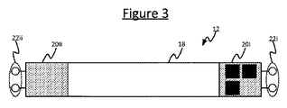
図3は、図1及び2に関連して説明されている照明器具100において用いられるランプ12のうちのいずれかを表し得る個々のTLEDランプ12を図示している。示されているように、ランプ12は、ケーシング18を含み、実際の照明素子(例えばLED)108は、そのケーシングによって形成される同じ光キャビティ内に一緒に入れられる。ケーシング18は、一般的には、外観を柔らかくするために拡散器の形態を取るが、それは透明又は半透明であってもよい。いずれにせよ、発光素子108は、給電されるときにケーシング18を通してそれらの照明を発するように構成される。実施例においては、ケーシング18は、単一の連続した材料片、例えば、単一のプラスチック片から形成されてもよい。
FIG. 3 illustrates an
ランプ12は、少なくとも1つの端部口金20も含み、蛍光灯に取って代わるTLEDの場合には、ランプ12は、実際には、2つの端部口金20i、20iiを含む。各端部口金20i、20iiは、照明器具100のソケットを介してランプ12を安定器10に接続し、それによって、照明素子18を安定器10によって供給される電力に接続するための個別のコネクタ22を有する。蛍光灯の場合には、各コネクタ22は、実際には、受容フィラメントの両端子である2つの端子(一対のピン)を含むが、2つの端子が必要であるのは、蛍光灯の特有の要件であり、LEDベースのランプには必ずしも関係ないので、蛍光灯に取って代わるTLEDの場合には、各コネクタの2つの端子は、一般的には、短絡される。
The
更に、ランプ12の少なくとも1つの端部口金20iは、ランプ12が、符号化光を発する、無線制御される且つ/又はLEDをベースにした、蛍光灯又はフィラメント電球などのより従来のランプの代替品であるという事実に特有の構成要素である付加的な構成要素を収容するために用いられる。これらの付加的な構成要素は、(蛍光灯などの従来のランプに給電するために設計されている)安定器10によって供給される電力をLEDベースの照明素子108を駆動するのに適した電力に変換するためのLEDドライバ106を含む。ドライバは、安定器10によって供給されるAC電力を受け取り、それをDCに変換し、次いで、LEDベースの照明素子108(例えばLED)に給電し、それによって、照明素子18から所望の光出力を発させるためのほぼ一定の(しかし、実施例においては、調節可能な)電流供給に変換するために、整流器(図示せず)を介してランプ12のコネクタ22i、22iiに接続される。照明器具の電力供給回路10によって供給される電力が既にDCである場合には、整流器は必要とされないが、一般に、後付け可能なLEDベースのランプのシナリオでは、照明器具自身の電力供給回路(例えば安定器)10からの電力は実際はACであり、それ故、整流する必要があることに留意されたい。
Furthermore, at least one end cap 20i of the
更に、端部口金20i内の付加的な構成要素は、組込コントローラ104を含み、随意に、ランプ12を遠隔制御するための無線インターフェース28を含む。上述のように、コントローラ104は、ランプ12の組込メモリに記憶され、ランプ12の組込処理デバイス上で実行されるソフトウェアにおいて実施されてもよく、又はコントローラ104は、ハードウェア回路、若しくはその2つの組み合わせにおいて実施されてもよい。無線インターフェース28は、例えば、ZigBee、Wi-Fi、802.15.4又はBluetooth(登録商標)トランシーバなどの無線受信機又はトランシーバの形態を取り得る。
In addition, additional components within the end cap 20 i include an embedded
実施例においては、照明器具4内のランプ12間の最良の通信のための設置を助けるために、付加的な構成要素を収容する端部口金20iは、1つ又は複数の物理的な(例えば、目に見える)マークで印をつけられてもよい。例えば、無線機がある端部に物理的なマークが設けられてもよく、設置者は、照明器具内でマークを集めるよう指示されてもよい。他の例においては、一方の端部20iには或る色のマークを備え、他方の端部20iiには別の色のマークを備える色分けが用いられてもよい。例えば、一方の口金には赤色の点が設けられ(随意に、他方の口金には青色の点が設けられ)、同じ色の口金を一緒にするという指示が供給されてもよい。このようにして、ランプ12は、照明器具100内で所定の既知の向きを与えられる。
In an embodiment, the end cap 20i that houses the additional components is one or more physical (e.g., to facilitate installation for best communication between the
構成要素28、104、26は、必ずしも同じ端部口金20内に収容される必要はなく、必ずしも端部口金のうちの1つに収容される必要もないことにも留意されたい。これは単に説明のための例である。
It should also be noted that the
オプションの無線インターフェース28が含まれる場合には、コントローラ104は無線インターフェース28(及びLEDドライバ106)に接続される。コントローラ104は、無線インターフェース28を用いて、専用の遠隔制御デバイス、無線壁スイッチ若しくは壁パネル、又はスマートフォン、タブレット、ラップトップコンピュータ若しくはデスクトップコンピュータのようなユーザ端末において実行する照明制御アプリケーションなどの手動又は自動照明コントローラ(図示せず)から照明制御コマンドを受信するよう構成される(例えばプログラムされる)。それに応じて、コントローラ104は、次いで、受信した制御コマンドに従って照明素子108の光出力を制御するためにドライバ106を制御する。例えば、これは、光をオン若しくはオフにすること、光出力を増光若しくは減光すること、光出力の色を変えること、又は動的な(時間変化する)照明効果を作成することを含み得る。例えば、コントローラ104は、光出力を調光するためにLED108に供給される電流レベルを調節することができ、且つ/又は光出力の全体的な色を調節するためにLED108のうちの異なる色のもの若しくはサブアレイに供給される電流レベルを調節することができる。
If the optional wireless interface 28 is included, the
更に、ランプ12が無線調光又は色制御を可能にするかどうかという問題は別として、本目的のためのコントローラ104の主な機能は、発光素子108によって発せられる照明の特性、一般的には強度(即ち、明るさ)を変調し、それによって、信号を、発せられる照明に符号化するように(ドライバ106を介して)照明の放射を制御することである。実施例においては、この信号は、検出装置110にアクセス可能なデータベースにおいてIDコードにマッピングされた或る特定の情報、例えば、ランプ12の位置を検索するために用いられ得るIDコードを含む。
Furthermore, apart from the question of whether the
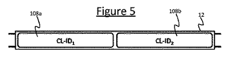
実際、本開示によれば、照明素子108は、各々が発光素子108のうちの1つ以上を含む少なくとも2つの別々に制御可能なセグメント108a、108bに分けられ、コントローラ104は、異なる個別IDコード、CL-ID1及びCL-ID2を発するようセグメント108a、108bの各々を制御するよう構成される。これの例は図4において図示されており、ここで、ランプ12は、ランプ12の長さに沿って互いに端から端まで配設されるLEDの2つの別々のまっすぐな列を含む直線状に配設されている発光素子108(例えばLED)で直線(例えばTLEDのような管)状を取る。従って、2つのコードの各々は、直線状ランプ12の異なる端部を表す。
In fact, according to the present disclosure, the
検出装置110のデコーダ114は、カメラ112によってランプ112の画像が取り込まれるときに、ランプ12の画像から両方のIDコードを検出及び復号するよう構成される。CL-IDデコーダ114は、TLEDの画像を2つの部分108a、108bに分け、各部分から別々にCL-IDを導き出す。次いで、デコーダ114は、コードの各々を個別の情報にマッピングするデータベースにおいて両方のコードを検索することができる。例えば、コードの一方又は両方が、(例えばコミッショニングから知られる)ランプ12の位置にマッピングされてもよく、コードの各々が、ランプ12のどの端部をコードが表すかを区別する。データベースは、検出装置110内にローカルに含まれてもよく(例えば、検出装置110がスマートフォン、タブレットなどである場合には、ローカルメモリに記憶されてもよく)、又はデコーダ114は、検出装置110と遠隔エンティティとの間の任意の有線接続及び/若しくは無線接続を介して(1つ以上の地理的場所に1つ以上のサーバユニットを有する)サーバなどの遠隔エンティティからデータベースにアクセスするよう構成されてもよい。例えば、この接続は、検出装置110と無線アクセスポイント又はルータとの間のローカル無線接続を介し、次いで、インターネット及び/又は会社のイントラネットなどの有線ネットワークを介する接続を介するものであってもよい。別の例として、接続は、モバイルセルラーネットワークを介するものであってもよい。本明細書で用いられているようなデータベースという用語は、如何なる特定のタイプのデータ構造にも限定されず、データベースは、小さなルックアップテーブルから大きなデータベースまで任意の形態を取り得ることにも留意されたい。
The
どのIDがランプ12のどの端部を表すかを知り、取り込まれた画像内の2つのセグメント108a、108bの位置とこれを比較することによって、デコーダ110はランプに対するカメラ112の向きを検出することができる。従って、単一のランプ12のみの画像に基づいて、即ち、カメラ112の視野内に単一のランプしかない状態で、カメラ112(例えば、スマートフォンカメラ)の向きを検出することが可能である。両方のコードもセグメント108a、108の各々の位置にマッピングする場合には、受信信号強度、飛行時間及び/又は到来角などの受けた光の位置依存特性を測定し、三角測量、三辺測量、多辺測量又はフィンガープリント法などの位置決め技術を適用することによって、ランプ12に対するカメラ112の位置を決定することも可能であり得る。三角測量、三辺測量又は多辺測量は、一意解を得るためには通常3つの基準点を必要とするが、上記のようにカメラ112の向きも知られている(即ち、デコーダ114が、カメラ112がどの方向からランプ12に面しているかを知っている)場合には、2つの基準点108a、108bのみに基づいて位置決め計算に対する一意解を得ることが可能であることに留意されたい。
By knowing which ID represents which end of the
図6において示されているように、ランプ12は、両方とも照明器具位置データベースに含まれている2つの基準点a(xa、ya)とb(xb、yb)を持つ。従って、1つのTLEDが、既存のVLC屋内測位システムにおける2つの照明器具の機能を有することができ、正確な位置決め及び方位測定を供給することができる。
As shown in FIG. 6, the
更に、検出を助けるために、ランプ12(例えばTLED)の両側108a、108bのCL-IDは関連付けられている。例えば、一方の側108aのコードCL-ID1が、Nである場合、他方の側108bのコードCL-ID2は、N+1、又はより広くはNプラス若しくはマイナス所定のオフセット、又はNに所定の係数を乗じたもの、又は(一方が他方の既知の関数である)それらの間に何らかの他の所定の数学的関係を有するものである。各半分に対して関連コードを用いることの利点は、デコーダ114によるより速いVLC検出である。例示的な検出プロセスは以下の通りである。
Further, to aid detection, the CL-IDs of both
デコーダ114は、カメラ112によって取り込まれた1つ又は複数の画像を分析して、取り込まれた画像において1つ以上の「光の塊(light blob)」、即ち、発光領域を識別する。更に、デコーダ114は、それが現在用いられている環境109に関する、2コードランプが環境109に取り付けられているという事実(又はより広くはランプ12ごとのコード数)を少なくとも含む、ランプ12についての所定の情報を有する。所定の情報は、環境内のランプ12の形状を示すものも含んでもよい(例えば、ランプがTLEDであることを知ることは、ランプが各々管状であることを示し、又はTLのモデルを知ることは、デコーダ114がその長さ又は相対寸法を知ることを意味する)。通常、所与の環境109、例えば、スーパーマーケット全体にわたって同じタイプの器具100内の同じタイプのランプ12が取り付けられるか、又は少なくとも相対的に少数の所定の種類のランプ12しか存在しない。したがって、カメラ112がどの環境109(即ち、会場)の画像を取り込んでいるかについての知識は、デコーダ114が探しているランプ12の1つ又は複数のタイプについての知識を与える。例えば、検出装置110(例えばスマートフォン)は、例えば、あまり正確ではないが、それでも異なる会場を識別するのに十分正確である位置決め方法を通して、検出装置110がどの会場内にあるのかを検出するための符号化光以外の手段(GPS、Core OS location)を有してもよい。他の例においては、会場の識別(identity)は、ユーザによって手動で入力されてもよい。どのような手段によって決定されても、デコーダ114は、次いで、識別された会場において予想されるランプ12の1つ又は複数のタイプを検索し得る。これは、デコーダと同じデバイス(例えば、スマートフォン)にローカルに記憶されたローカルデータベースに基づいてもよく、又はデコーダ114は、有線若しくは無線の接続若しくはネットワーク(例えば、前述のいずれか)を介してサーバ(例えば、クラウドサービス)などの遠隔記憶場所に記憶されたデータベースにアクセスしてもよい。他の例においては、デコーダ114は、単に、1つ又は複数の或る特定のタイプのランプ12を想定するよう予めプログラムされていてもよい。
The
実施例においては、デコーダ114は、まず、検出を助けるためにランプ12の形状を用いてもよい。例えば、スーパーマーケットのような会場では、符号化光を備える光源と、符号化光を備えない光源とがあり得る。デコーダは、「光の塊」を識別し、各々から符号化光IDを導き出すことを試みる。非符号化光源である光の塊の分析において時間を無駄するのを避けるために、デコーダは光の塊の形状を分析する。(非符号化光TLEDを除く)他の形状の光の塊は無視され得る。TLEDのようなランプ12は、一般に、明確に規定された形状を持ち、従って、デコーダ114にはっきりと認識可能である。更に、本明細書に開示されている実施例においては、デコーダ114は、この形状を2つの半分に分割し、各半分を分析して個別コードを検出する(又はより広くは、ランプ12ごとに存在するコードと同じ数の部分に形状を分割する)。ランプ12ごとのコード数、及び随意に各セグメント108a、108bの形状は、例えば、前述のような会場についてのデコーダの知識に基づいて、デコーダが検出しようとしている所定のタイプのランプ12に与えられている所定の特徴としてデコーダに既知であり得る。
In an embodiment, the
場合によっては、遷移が隣接するセグメント108a、108bの間のどこにあるかを検出することに幾らかの困難があり得ることに注意されたい。これに対する解決策は少なくとも2つある。第1の解決策は、2つのコードを備える領域の間に暗い隙間を設けるものである(が、これの不利な点は、隙間が人間に見えることである)。第2の解決策は、コード間の遷移がランプの中央にあるという知識を用いるように検出器114をプログラムするものである。いずれにせよ、検出器は、好ましくは、検出のために中央から離れた領域を用いるだろう(従って、はっきりしない領域からコードを検出しようとすることを避けるだろう)。
Note that in some cases there may be some difficulty in detecting where the transition is between
従って、デコーダ114は、符号化光コードを求めて取り込まれた画像を検索することができる。このような符号化光検出は、デコーダ114が特定の予め指定されたコードを検索している場合には、あらゆる任意の未知の信号を検出しようとするよりはむしろ速い。これ自体は、1つ又は複数の取り込まれた画像内の光源を検出することに基づいて動作する既知の符号化光デコーダの特性である。それ故、デコーダ114を助けるために、本開示の実施例によれば、ランプ12内の異なるセグメント108a、108bは、異なるが関連付けられたコードを持つよう構成される。例えば、前述のように、第1セグメント108aのコードがNである場合には、第2セグメントのコードはN+1であり得る。デコーダ114は、最初に、コードのうちの1つを求めて取り込まれた画像を検索するよう構成され、これは、あらゆる未知の任意のコードに対する(即ち、最初のコード自体についての所定の知識が全くない、より遅い)オープンエンドサーチ(open-ended search)であってもよい。他の例においては、デコーダ114は、環境109内のランプ12によって発せられるコードは所定の有限集合の中からのものであるだろうという所定の知識を用いて構成されてもよく、その場合には、それは検索を制限し得る(これは、このような所定の知識が利用可能であるので、より高速である)。従って、いずれにしても、デコーダ114は、最初に、ランプ12内の発光セグメント108a、108bのうちの一方のコードを検出する。次に、デコーダ114は、コード間の関係についてのデコーダ114の所定の知識に基づいて、ランプの他方の隣接セグメント108b、108aにおいて関連コード(又は3つ以上のセグメントが存在する場合には他のセグメントにおいて他のコード)を探すよう構成される。従って、例えば、デコーダ114が、ランプ114が2つの符号化発光セグメントを有し、ランプ内のコードがN及びN+1という関係によって関係付けられているという情報を用いて構成される場合には、デコーダ114は、所与のランプ12において1つのコードを見つけたら、隣接セグメントにおいて同じコード+1又は-1を検出しようと試みることしか必要としない(デコーダ114は、デコーダ114がどちらを見つけたのかを知らない。即ち、デコーダ114は、Nをチェックすることを必要とするN+1を見つけたかもしれず、又はデコーダ114は、N+1をチェックすることを必要とするNを見つけたかもしれない)。これは、あらゆる2つの任意の関連付けられていないコードを求めて画像のオープンエンドサーチを実施するよりも速い。
Therefore, the
実施例においては、各発光セグメント108a、108bからの符号化光信号は、検出されるべき発せられるコードに基づいて生成される冗長情報、例えば、CRCデータ又はチェックサムを更に含むことにも留意されたい。この場合には、デコーダ114は、例えば、CRCチェックを実施することによって、又はチェックサムをチェックすることによって、冗長情報を用いて、各コードが正しく検出されたことを確認するよう構成され得る。
It is also noted that in an embodiment, the encoded optical signal from each light emitting
関連付けられているコードの別の例が、図7に図示されている。ここでは、一方の側の電流が増加するとき、他方の側の電流は減少する。即ち、コードのうちの一方の波形は、他方の波形の逆である。これは、より速い検出を可能にするだけでなく、総電流が経時的に一定であるという更なる利点も有する。実施例においては、これは、ドライバ106がより単純且つより安価にされ得ることを意味する。(元々は蛍光灯用であった安定器からの電流である)TLEDのための外部駆動電流は一定であることから、時間的に変動させる唯一の方法は、コンデンサ又はコイルに電気エネルギを一時的に蓄えるものである。コンデンサ及びコイルは、高価であり、十分な寿命を得るために注意を必要である。しかしながら、図7に示すように総出力電流が経時的に一定である場合には、電気エネルギの蓄積は必要とされない。
Another example of associated code is illustrated in FIG. Here, when the current on one side increases, the current on the other side decreases. That is, one waveform of the code is the opposite of the other waveform. This not only allows for faster detection but also has the additional advantage that the total current is constant over time. In the example, this means that
更に、符号化光を作成する幾つかの方法は、環境の占有者に不快であり得る且つ/又は他の装置(例えばバーコードスキャナ)に干渉し得るフリッカを引き起こす。しかしながら、図7において示されているような、一方のコードCL-ID1が他方のコードCL-ID2の逆である実施例においては、総光出力は経時的に一定であり、(ランプの環境を照明する光における)フリッカの発生を防止する。カメラ112のみがランプ12の2つの部分108a、108bを識別することができる。
In addition, some methods of creating encoded light cause flicker that can be uncomfortable to environmental occupants and / or can interfere with other devices (eg, barcode scanners). However, in an embodiment in which one code CL-ID1 is the opposite of the other code CL-ID2, as shown in FIG. 7, the total light output is constant over time (the lamp environment Prevent flickering (in the illuminating light). Only the
他の実施例においては、ランプ12は、(2つのセグメントの場合には、2つの発光部108a、108bの間のランプ12の中央に、例えば、LEDの2つの列の間のTLEDの中央に)異なるCL-IDを持つ領域を分離する非照明領域を有するよう構成される。これは、カメラ112による識別及び画像からCL-ID1及びCL-ID2を導き出すための検出SWを容易にする。即ち、デコーダ114は、セグメント間の非発光分離に少なくとも部分的に基づいて、取り込まれた画像において2つ(又はそれ以上)の異なるセグメント108a、108bの位置を認識し、分離するよう構成される。
In another embodiment, the
コードの分離可能性を助けるための別の代わりの又は付加的な技術として、2つのセグメント108a、108bのコードは、同時には発せられず、好ましくはそれらの間で重複がないようにして、好ましくは周期的に、異なる時間に次々に発せられる。利点は、隣接する発光領域の2つの異なるコードの検出は、領域間に暗い隙間がない場合には困難であるが、コードが、好ましくは間に休止を挟んで、次々に発せられる場合には、CL-ID1とCL-ID2との両方が検出され得ることである。
As another alternative or additional technique to aid in code separability, the codes of the two
幾つかの実施例においては、デコーダ114は、更に、不測の事態として、任意の所与の時間にランプ12の2つのセグメント108a、108bが視野内にない場合には、異なるやり方で向きを検出するよう構成され得る。取り付けている高さ及びランプサイズが既知である場合には、デコーダ114は、ランプ12全体が視野内にあるのか、又はランプ12の一部しか視野内にないのかを画像から検出することができる(例えば図8参照、図8において、点線800は、ランプ12の、カメラ112の視野内にある部分を表わしている)。ランプ12全体が視野内にある場合には、ランプは2つの等しい部分に分けられ、各部分のコードが検出される。しかしながら、図8において示されているように、視野内にランプ全体がない場合には、デコーダ114は、視野内にある部分800の各半分からコードを識別しようとする。一方はコードをもたらすだろうが、他方からはコードは取得されることができない。この情報から、デコーダ114はランプの識別及び向きを導き出すことができる。一般に、VLC屋内測位ソフトウェアは、カメラ112が視野内に有する全ての「光の塊」を分析し、それらの形状に基づいて符号化を有すると期待されるものを選択することから開始し、次いで、このような塊の各々のコードを識別する(これは時間のかかるプロセスであり、従って、非符号化光の「光の塊」において時間を無駄にすることは可能な限り避けられる)。検出器114が、識別されていない符号化光IDがどちら側にあるのかを「知る」ように、少なくとも1つのランプ12の全体が視野内にあるのであれば、TLED(又は他の符号化ランプ)12の形状及び2つのコードのうちの一方が識別される場合には、正確な位置決めプラス方位測定にはそれで十分である。換言すれば、ランプ12は非対称形をしており、従って、1つのコードで正確な位置決め及び方位測定が可能である。即ち、検出器114が、ランプ12の1つの半分108aからのコードを識別し、(光の塊から認識可能な)同じランプ12の別の部分108bが存在することを見る場合、ランプ12がカメラ112に対してどのように向けられているかは明らかである。光の塊の角度に部分的に基づいて、光の塊は対称性を有し、依然として2つの可能性が存在するが、これら2つの向きのうちどちらが正しいかは、1つの符号化光IDから得られる。
In some embodiments, the
本発明のとりわけ有利なアプリケーションは、会場イネーブルメント(venue enablement)にある。会場イネーブルメントは、照明器具位置データベースを作成するための既知のプロセスである。これは、スーパーマーケットなどの特定の会場内の全ての照明器具の符号化光ID及びそれらの位置のデータベース(即ち、コミッショニングプロセスの一部)である。データベースは、デバイス110の位置及び向きを取得するためにユーザの検出装置110(例えば、スマートフォン)における屋内測位ソフトウェアによって用いられる。本明細書において開示されている実施例によれば、2つの基準点a及びb(図6参照)の会場イネーブルメントは、照明器具と同じ方法で、しかし、ランプごとに二箇所を用いることで、可能である。これは、会場イネーブルメントを行う人にとってはより困難であるかもしれない。しかしながら、現在の方法及びツールの以下の拡張がこれを軽減し得る。即ち、とりわけユーザフレンドリな実施例においては、TLEDの2コード特性が、(例えば、AutoCADドローイング及びAutoCADプラグインを介して)会場イネーブルメント(VE)ツールに入力される。例えば、VEツールは、マップ上のどのランプが取り込まれているかに加えて、ランプ100の向きをユーザが示すことを可能にする。VEは、現在行われているように、ランプごとに行われるが、ツールは、数秒間、視野内に少なくとも2つのTLEDを有することを必要とする。VEツールは、どのCL-IDがどちら側にあるのかを自動的に識別することができる。
A particularly advantageous application of the present invention is in venue enablement. Venue enablement is a known process for creating a luminaire location database. This is an encoded light ID of all luminaires in a particular venue, such as a supermarket, and a database of their locations (ie, part of the commissioning process). The database is used by indoor positioning software on the user's detection device 110 (eg, a smartphone) to obtain the position and orientation of the device 110. According to the embodiments disclosed herein, the venue enablement of the two reference points a and b (see FIG. 6) is the same as the luminaire, but using two locations per lamp. Is possible. This may be more difficult for those who do venue enablement. However, the following extensions of current methods and tools can alleviate this. That is, in a particularly user-friendly embodiment, the TLED's two-code characteristics are input to a venue enablement (VE) tool (eg, via an AutoCAD drawing and an AutoCAD plug-in). For example, the VE tool allows the user to indicate the orientation of the
上記の実施例は、様々なシナリオにおいて有利であり得るが、正確な位置決め及び方位測定が、会場全体にわたっては必要とされず、むしろ、或る特定の小さな領域だけでしか必要とされない会場においてとりわけ有利であり得る。例えば、空港のような会場においては、会場のほとんどの領域ではより低い精度で十分であることから、会場全体にわたっては、BLE(Bluetooth(登録商標) Low Energy)又はWi-FiなどのRFをベースにした技術を用いて位置決めが供給されてもよいが、1つ以上の特定の領域では、例えば、人々を左側若しくは右側に誘導するために、セキュリティカウンタにわたって人々を分散させるために、及び/又は入場規制などのために、向き及びより正確な位置決めが、望まれ、必要とされ得る。これらの領域においては、VLCをベースにした位置決めが、本明細書に開示されている技術のうちの1つ以上を用いて供給され得る。別の例は、方向(例えば、左右)、ショーウィンドウ内のアイテムについての情報を与えるために、及び/又は待ち行列を編成するためなどに符号化光照明領域が用いられ得るショッピングモールである。 The above embodiments may be advantageous in various scenarios, but especially in venues where precise positioning and orientation measurements are not required throughout the venue, but rather only in certain small areas. Can be advantageous. For example, in venues such as airports, lower accuracy is sufficient in most areas of the venue, so the entire venue is based on RF such as BLE (Bluetooth® Low Energy) or Wi-Fi. Positioning may be provided using the techniques described above, but in one or more specific areas, for example, to direct people to the left or right, to distribute people across security counters, and / or Orientation and more accurate positioning may be desired and required for admission control and the like. In these areas, VLC-based positioning can be provided using one or more of the techniques disclosed herein. Another example is a shopping mall where encoded light illumination areas can be used to provide information about items in a show window (eg, left and right), and / or to organize a queue.
上記の実施例はほんの一例として記載されていることは理解されるであろう。 It will be appreciated that the above embodiment has been described by way of example only.
例えば、本開示の範囲は、2つの個別コードを備える2つのセグメント108a、108bだけに限定されるわけではく、それよりむしろ、各々が自身の個別コードを備えるそれ以上のCL放射発光セグメントが含まれてもよい。これは、位置及び/又は向きの計算を実施するために単一のランプ12の画像からデコーダに利用可能になる情報の解像度を高めるだろう。更に、本開示の範囲は、位置決め又は向き検出に限定されない。他の使用事例においては、2つ(又はそれ以上)のコードが他の目的ために用いられてもよく、例えば、或るコードは、位置をベースにした広告にマッピングする一方で、別のコードは、同時に、照明器具100の位置、又は展示に関する事実情報などの別の情報にリンクする。
For example, the scope of this disclosure is not limited to only two
更に、上記の実施例においては、2つのコードは、ランプ12自身に組み込まれるコントローラ104によって適用されるが、他の実施例においては、コントローラ104はランプ12の外部にあってもよい。例えば、コントローラ104は、その代わりに、照明器具100に組み込まれ、接続した機械的コネクタ22を介してランプ12の2つ以上の個別のセグメント108a、108bにコードを通信するよう構成されてもよい。別の例として、コントローラ104は、照明器具100の外部のエンティティに組み込まれてもよく、例えば、サーバに実装されてもよく、又はビルコントローラ、集中照明制御ユニット若しくは照明ブリッジに組み込まれてもよい。この場合には、コントローラ104は、外部エンティティから個別のセグメント108a、108bへ、外部エンティティと照明器具との間の任意の有線及び/又は無線接続を介して(例えば、WLAN、ローカルイーサネット(登録商標)ネットワーク、及び/又はインターネットを介して)、次いで、機械的コネクタ22の接続を介して、コードを通信し得る。
Further, in the above embodiment, the two codes are applied by the
それ故、機械的コネクタ22の機能は必ずしも電力を供給することだけではないことにも留意されたい。実施例においては、コネクタ22はまた、発せられるべきコードを発光セグメント108a、108bに供給するために、及び/又は他のデータを送るためなどに、例えば、照明器具から若しくは照明器具を通してランプ12へ(全体的な照明レベルを増光若しくは減光する、又はその色を変えるような)照明制御コマンドを送るために、又はランプ12から照明器具100へ又は照明器具100を通して状態報告を送り返すために、照明装置100とランプ12との間にデータ信号を供給し得る。これは、電力接続自体のうちの1つにおいて信号を送ることによって、又はコネクタ22に1つ若しくは複数の別個のデータピンを含めることによって、達成され得る。他の実施例においては、機械的コネクタ22がランプ12に電力を供給する機能を持つ必要は全くない。その代わりに、ランプ12は、バッテリなどのそれ自身の内部電源を有してもよく、機械的コネクタ22は、ランプを照明器具内に物理的に保持する機能しか持たなくてもよく、又はそれにデータ接続を加えた機能しか持たなくてもよい。
Therefore, it should also be noted that the function of the mechanical connector 22 is not necessarily just supplying power. In an embodiment, the connector 22 may also be supplied to the
他の実施例においては、ドライバ106及び変調の実施のための様々な異なる可能性がある。また、機械的コネクタ22は、必ずしも、単一の接続要素に限定されない(同様に、照明器具100における相補コネクタに限定されない)。例えば上記の実施例においては、異なる発光セグメント108a、108bが、照明器具100の電力供給回路10(例えば、安定器)への同じ機械的コネクタ22を共有する。これは、両方(又は全て)のセグメント108a、108bが、コネクタ22の同じコネクタ要素を介して供給される電力によって給電されることを意味し得る。他の例においては、異なるセグメント108a、108bの各々は、照明器具100から異なる個別のコネクタ要素を介して供給される異なる電力入力を介して給電されてもよい。これは、異なるドライバ及び変調構成の可能性も与える。例えば、実施例においては、ドライバ106は必ずしもランプ12に組み込まれる必要はなく、且つ/又は変調は必ずしもランプにおいて適用される必要はない。その代わりに、ドライバ106は、照明器具100に組み込まれてもよく、その場合には、ドライバによって出力される電力の変調は、照明器具100において適用されてもよく、又はランプにおいて適用されてもよい。
In other embodiments, there are various different possibilities for the
例えば、(上で例示したような)T-LED交換の場合には、ドライバ106は、T-LED内にあり、異なる発光セグメント108aは、照明器具100によって供給される電力に接続するために同じコネクタ要素を共有してもよい。この場合には、ランプ12内のドライバ106が、組込又は外部コントローラ104の制御下で、この2つ(又はそれ以上)の別々に変調された電力から、2つ(又はそれ以上)の別々の発光セグメント108a、108bを駆動する出力を生成する。しかし、別のタイプのデバイス、例えば、照明器具100内に変調を実施するドライバを備えるデバイスの場合には、ドライバ106はまた、ランプ12に接続する2つ(又はそれ以上)の別々の機械的コネクタ要素を介する2つ(又はそれ以上)の出力、第1コネクタ要素を介して第1セグメント108aを駆動するID1で変調される一方の出力、及び別の第2コネクタ要素を介して第2セグメント108aを駆動するID2で変調される他方の出力を有してもよい。別の代案として、照明器具内の2つの非変調出力を持つドライバ、及びドライバと個別の発光セグメント108a、108bとの間に接続される2つの個別のアドオン変調ユニットがあってもよい。
For example, in the case of a T-LED replacement (as exemplified above), the
当業者は、請求項に記載の発明を実施する際に、図面、明細及び添付の請求項の研究から、開示されている実施例に対する他の変形を、理解し、達成し得る。請求項において、「有する」という用語は、他の要素又はステップを除外せず、単数形表記は、複数の存在を除外しない。請求項において列挙されている幾つかの要素の機能を、単一のプロセッサ又は他のユニットが果たしてもよい。単に、特定の手段が、互いに異なる従属請求項において挙げられているという事実は、これらの手段の組み合わせが有利になるように用いられることができないことを示すものではない。コンピュータプログラムは、他のハードウェアと一緒に又は他のハードウェアの一部として供給される光学式記憶媒体又は固体媒体のような適切な媒体上に記憶及び/又は分散されてもよいが、インターネット又は他の有線若しくは無線電気通信システムを介するような他の形態で分散されてもよい。請求項における如何なる参照符号も、範囲を限定するものとして解釈されてはならない。 Those skilled in the art may appreciate and achieve other variations to the disclosed embodiments from a study of the drawings, specification, and appended claims, when practicing the claimed invention. In the claims, the word “comprising” does not exclude other elements or steps, and the singular form does not exclude the presence of a plurality. A single processor or other unit may fulfill the functions of several elements recited in the claims. The mere fact that certain measures are recited in mutually different dependent claims does not indicate that a combination of these measured cannot be used to advantage. The computer program may be stored and / or distributed on any suitable medium, such as an optical storage medium or solid medium supplied with or as part of other hardware, Or it may be distributed in other forms, such as via other wired or wireless telecommunication systems. Any reference signs in the claims should not be construed as limiting the scope.
Claims (15)
異なる前記発光セグメントの前記コードを制御するよう構成されるコントローラであって、前記コードが、前記コードのより速い検出のために前記コード間に所定の関係を有するコントローラとを有する照明装置であって、
前記所定の関係が、或る個別コードが別の個別コードの既知の関数であるような数学的関係である照明装置。 A lamp comprising a mechanical connector for releasably connecting the lamp to a luminaire via a complementary connector of the luminaire, and further comprising a plurality of light emitting segments each at a different location within the lamp A lamp operable to emit illumination, each of the light emitting segments in the lamp being modulated to transmit a different individual code;
A controller configured to control the codes of different light emitting segments, the code comprising a controller having a predetermined relationship between the codes for faster detection of the codes, ,
The lighting device, wherein the predetermined relationship is a mathematical relationship in which one individual code is a known function of another individual code.
前記発光セグメントが、2つより多いセグメントから成り、前記関係が、前記複数のセグメントの前記コードが互いに対して線形のシーケンスに従うという関係である請求項2に記載の装置。 The light-emitting segment is composed of two segments, a first segment and a second segment, and the relationship is that the code of the second segment is obtained by adding or subtracting a predetermined value to the code of the first segment. 3. The apparatus of claim 2, wherein the relationship is, or the light emitting segment consists of more than two segments, and the relationship is a relationship in which the codes of the plurality of segments follow a linear sequence with respect to each other. .
前記カメラによって取り込まれた前記ランプの前記画像から前記コードの検出をし、前記コードの前記検出を前記コード間の所定の関係に基づいて実施するよう構成されるデコーダとを有する検出装置であって、
前記所定の関係が、或る個別コードが別の個別コードの既知の関数であるような数学的関係である検出装置。 A lamp for capturing an image of a lamp that includes a plurality of light emitting segments each at a different location in the lamp, wherein each of the light emitting segments in the lamp is modulated to transmit a different individual code A camera that is operable to emit directed illumination;
A detector comprising: a decoder configured to detect the code from the image of the lamp captured by the camera and to perform the detection of the code based on a predetermined relationship between the codes; ,
A detection device wherein the predetermined relationship is a mathematical relationship in which one individual code is a known function of another individual code.
カメラ及びデコーダを含む検出装置であって、前記デコーダが、前記カメラによって取り込まれた前記ランプの画像から前記コードの検出をし、前記コードの前記検出を前記コード間の前記所定の関係に基づいて実施するよう構成される検出装置とを有するシステム。 The lighting device according to any one of claims 1 to 12, connected to the lighting fixture via the mechanical connector of the lamp and a complementary connector of the lighting fixture;
A detection device including a camera and a decoder, wherein the decoder detects the code from an image of the lamp captured by the camera, and the detection of the code is based on the predetermined relationship between the codes. And a detection device configured to be implemented.
異なる個別コードを送信するよう変調された照明を発するよう前記ランプ内の前記発光セグメントの各々を制御するステップであって、前記制御するステップが、異なる前記発光セグメントの前記コードを、前記コードのより速い検出のために前記コード間に所定の関係を有するように制御するステップを含み、前記所定の関係が、或る個別コードが別の個別コードの既知の関数であるような数学的関係であるステップと、
カメラを用いて前記ランプの画像を取り込むステップと、
デコーダを用いて前記画像から前記コードの検出をするステップであって、前記検出が、前記異なる発光セグメントの前記コード間の前記所定の関係に基づくステップとを有する方法。 Connecting a lamp, comprising a plurality of light emitting segments, each at a different location within the lamp, to a luminaire that supplies power to power each of the light emitting segments;
Controlling each of the light emitting segments in the lamp to emit illumination modulated to transmit different individual codes, the controlling step comprising: Controlling to have a predetermined relationship between the codes for fast detection, the predetermined relationship being a mathematical relationship such that one individual code is a known function of another individual code Steps,
Capturing an image of the lamp using a camera;
Detecting the code from the image using a decoder, wherein the detection is based on the predetermined relationship between the codes of the different light emitting segments.
Applications Claiming Priority (3)
| Application Number | Priority Date | Filing Date | Title |
|---|---|---|---|
| EP16180479.4 | 2016-07-21 | ||
| EP16180479 | 2016-07-21 | ||
| PCT/EP2017/067008 WO2018015176A1 (en) | 2016-07-21 | 2017-07-06 | Lamp with coded light functionality |
Publications (2)
| Publication Number | Publication Date |
|---|---|
| JP2019526888A true JP2019526888A (en) | 2019-09-19 |
| JP2019526888A5 JP2019526888A5 (en) | 2020-08-13 |
Family
ID=56507437
Family Applications (1)
| Application Number | Title | Priority Date | Filing Date |
|---|---|---|---|
| JP2019503244A Pending JP2019526888A (en) | 2016-07-21 | 2017-07-06 | Lamp with coded light function |
Country Status (5)
| Country | Link |
|---|---|
| US (1) | US20190280769A1 (en) |
| EP (1) | EP3488667A1 (en) |
| JP (1) | JP2019526888A (en) |
| CN (1) | CN109691232A (en) |
| WO (1) | WO2018015176A1 (en) |
Families Citing this family (8)
| Publication number | Priority date | Publication date | Assignee | Title |
|---|---|---|---|---|
| JP2019132673A (en) * | 2018-01-31 | 2019-08-08 | 沖電気工業株式会社 | Terminal device and position detection system |
| WO2020000021A1 (en) * | 2018-06-29 | 2020-01-02 | Monash University | Visible light positioning receiver arrangement and two stage positioning method |
| US11558949B2 (en) | 2018-10-26 | 2023-01-17 | Current Lighting Solutions, Llc | Identification of lighting fixtures for indoor positioning using color band code |
| CN111757010B (en) * | 2019-05-23 | 2021-10-22 | 深圳市瑞立视多媒体科技有限公司 | Active optical rigid body configuration method, system and terminal equipment |
| WO2020232704A1 (en) * | 2019-05-23 | 2020-11-26 | 深圳市瑞立视多媒体科技有限公司 | Rigid body identification method and apparatus, system, and terminal device |
| GB201913977D0 (en) * | 2019-09-27 | 2019-11-13 | Purelifi Ltd | Optical wireless communication (OWC) unit |
| US11176810B2 (en) * | 2020-04-10 | 2021-11-16 | The Boeing Company | Wireless control of a passenger service unit |
| US11387902B2 (en) * | 2020-04-10 | 2022-07-12 | The Boeing Company | Wireless control of a passenger service unit using a personal device of a passenger |
Citations (4)
| Publication number | Priority date | Publication date | Assignee | Title |
|---|---|---|---|---|
| JP2006115539A (en) * | 2005-12-05 | 2006-04-27 | Nakagawa Kenkyusho:Kk | Light-emitting device and visible light data transmission system |
| US20150280820A1 (en) * | 2014-03-25 | 2015-10-01 | Osram Sylvania Inc. | Techniques for adaptive light modulation in light-based communication |
| JP5936800B1 (en) * | 2015-03-16 | 2016-06-22 | 三菱電機株式会社 | Optical communication system and optical signal generator |
| JP2016126902A (en) * | 2014-12-26 | 2016-07-11 | パナソニックIpマネジメント株式会社 | Lighting fixture and visible light communication system |
Family Cites Families (21)
| Publication number | Priority date | Publication date | Assignee | Title |
|---|---|---|---|---|
| JP4689412B2 (en) * | 2005-08-31 | 2011-05-25 | 京セラ株式会社 | Transmitting apparatus and communication system |
| US8405323B2 (en) * | 2006-03-01 | 2013-03-26 | Lancaster University Business Enterprises Limited | Method and apparatus for signal presentation |
| KR100891769B1 (en) * | 2007-05-30 | 2009-04-07 | 삼성전자주식회사 | Wireless visible light optical communication system |
| JP5441900B2 (en) * | 2007-07-16 | 2014-03-12 | コーニンクレッカ フィリップス エヌ ヴェ | Driving the light source |
| CN101430075B (en) * | 2008-03-17 | 2011-01-12 | 马田专业公司 | Location encoding of illuminating apparatus |
| KR101015643B1 (en) * | 2008-06-17 | 2011-02-22 | 삼성전자주식회사 | Visible light communication method and apparatus |
| BRPI1006706B1 (en) * | 2009-04-08 | 2019-12-10 | Koninl Philips Electronics Nv | remote controller, lighting system, method for assigning an identity to a light source in a coded light lighting system, and method for operating a lighting system |
| RU2012103598A (en) * | 2009-07-03 | 2013-08-10 | Конинклейке Филипс Электроникс Н.В. | METHOD AND SYSTEM FOR ASYNCHRONOUS LAMP IDENTIFICATION |
| US8414151B2 (en) * | 2009-10-02 | 2013-04-09 | GE Lighting Solutions, LLC | Light emitting diode (LED) based lamp |
| KR101654934B1 (en) * | 2009-10-31 | 2016-09-23 | 삼성전자주식회사 | Visible communication method and apparatus |
| BR112012017094A8 (en) * | 2010-01-15 | 2017-07-11 | Koninklijke Philips Electronics Nv | DETECTION SYSTEM FOR DETERMINING A FIRST REPEATING SEQUENCE OF N SYMBOLS INCLUDED IN A FIRST CODE, METHOD FOR DETERMINING A FIRST REPEATING SEQUENCE OF N SYMBOLS INCLUDED IN A FIRST CODE AND COMPUTER PROGRAM |
| JP5620707B2 (en) * | 2010-04-21 | 2014-11-05 | パナソニック株式会社 | Lighting system |
| KR20120064543A (en) * | 2010-12-09 | 2012-06-19 | 한국전자통신연구원 | Apparatus and method for light indication |
| EP2503852A1 (en) * | 2011-03-22 | 2012-09-26 | Koninklijke Philips Electronics N.V. | Light detection system and method |
| GB2496379A (en) * | 2011-11-04 | 2013-05-15 | Univ Edinburgh | A freespace optical communication system which exploits the rolling shutter mechanism of a CMOS camera |
| RU2678689C2 (en) * | 2013-07-04 | 2019-01-31 | Филипс Лайтинг Холдинг Б.В. | Determining orientation |
| US9551463B2 (en) * | 2013-08-19 | 2017-01-24 | Lunera Lighting Inc. | Retrofit LED lighting system |
| JP6473996B2 (en) * | 2014-06-12 | 2019-02-27 | パナソニックIpマネジメント株式会社 | Worker management system |
| US10020881B2 (en) * | 2014-11-25 | 2018-07-10 | Qualcomm Incorporated | Method and apparatus for transmitting secure VLC identifiers |
| CN104602416B (en) * | 2015-01-27 | 2016-04-13 | 深圳市洲明科技股份有限公司 | A kind of LED illumination lamp |
| US20160226585A1 (en) * | 2015-02-02 | 2016-08-04 | Blackberry Limited | Computing devices and methods for data transmission |
-
2017
- 2017-07-06 EP EP17735160.8A patent/EP3488667A1/en not_active Withdrawn
- 2017-07-06 CN CN201780044855.6A patent/CN109691232A/en active Pending
- 2017-07-06 JP JP2019503244A patent/JP2019526888A/en active Pending
- 2017-07-06 WO PCT/EP2017/067008 patent/WO2018015176A1/en unknown
- 2017-07-06 US US16/319,367 patent/US20190280769A1/en not_active Abandoned
Patent Citations (4)
| Publication number | Priority date | Publication date | Assignee | Title |
|---|---|---|---|---|
| JP2006115539A (en) * | 2005-12-05 | 2006-04-27 | Nakagawa Kenkyusho:Kk | Light-emitting device and visible light data transmission system |
| US20150280820A1 (en) * | 2014-03-25 | 2015-10-01 | Osram Sylvania Inc. | Techniques for adaptive light modulation in light-based communication |
| JP2016126902A (en) * | 2014-12-26 | 2016-07-11 | パナソニックIpマネジメント株式会社 | Lighting fixture and visible light communication system |
| JP5936800B1 (en) * | 2015-03-16 | 2016-06-22 | 三菱電機株式会社 | Optical communication system and optical signal generator |
Also Published As
| Publication number | Publication date |
|---|---|
| WO2018015176A1 (en) | 2018-01-25 |
| CN109691232A (en) | 2019-04-26 |
| EP3488667A1 (en) | 2019-05-29 |
| US20190280769A1 (en) | 2019-09-12 |
Similar Documents
| Publication | Publication Date | Title |
|---|---|---|
| JP2019526888A (en) | Lamp with coded light function | |
| US9883563B2 (en) | Directional lighting system and method | |
| US10772171B2 (en) | Directional lighting system and method | |
| US10601516B2 (en) | Emitting coded light from a multi-lamp luminaire | |
| JP6440902B2 (en) | Lamp with wireless communication | |
| EP2749141B1 (en) | Coded light transmission and reception for light scene creation | |
| US11949532B2 (en) | Camera-based commissioning | |
| JP2018531481A6 (en) | Lamp with wireless communication | |
| US9980337B1 (en) | Automated luminaire location identification and group assignment using light based sectorized communication for commissioning a lighting control system | |
| US10045415B1 (en) | Automated luminaire location identification and group assignment using light based communication for commissioning a lighting control system | |
| US20180054876A1 (en) | Out of plane sensor or emitter for commissioning lighting devices | |
| US20190182930A1 (en) | Method for calibration of lighting system sensors | |
| US11632173B2 (en) | Method and system for communicating via light signals | |
| WO2018215989A1 (en) | Automated luminaire location identification and group assignment using light based communication for commissioning a lighting control system | |
| WO2020030463A1 (en) | Method and controller for reducing the energy consumption of a lighting system | |
| WO2018015272A1 (en) | Detecting signals embedded in visible light | |
| WO2018215986A1 (en) | Automated luminaire location identification and group assignment using light based communication for commissioning a lighting control system |
Legal Events
| Date | Code | Title | Description |
|---|---|---|---|
| A521 | Request for written amendment filed |
Free format text: JAPANESE INTERMEDIATE CODE: A523 Effective date: 20200703 |
|
| A621 | Written request for application examination |
Free format text: JAPANESE INTERMEDIATE CODE: A621 Effective date: 20200703 |
|
| A977 | Report on retrieval |
Free format text: JAPANESE INTERMEDIATE CODE: A971007 Effective date: 20210528 |
|
| A131 | Notification of reasons for refusal |
Free format text: JAPANESE INTERMEDIATE CODE: A131 Effective date: 20210602 |
|
| A02 | Decision of refusal |
Free format text: JAPANESE INTERMEDIATE CODE: A02 Effective date: 20211221 |