JP2019521444A - Computer system and method for dynamic construction and on-line deployment of a motion-centric first principles process model for predictive analysis - Google Patents
Computer system and method for dynamic construction and on-line deployment of a motion-centric first principles process model for predictive analysis Download PDFInfo
- Publication number
- JP2019521444A JP2019521444A JP2019500348A JP2019500348A JP2019521444A JP 2019521444 A JP2019521444 A JP 2019521444A JP 2019500348 A JP2019500348 A JP 2019500348A JP 2019500348 A JP2019500348 A JP 2019500348A JP 2019521444 A JP2019521444 A JP 2019521444A
- Authority
- JP
- Japan
- Prior art keywords
- unit
- model
- plant
- process model
- modeled
- Prior art date
- Legal status (The legal status is an assumption and is not a legal conclusion. Google has not performed a legal analysis and makes no representation as to the accuracy of the status listed.)
- Pending
Links
Images


Classifications
-
- G—PHYSICS
- G05—CONTROLLING; REGULATING
- G05B—CONTROL OR REGULATING SYSTEMS IN GENERAL; FUNCTIONAL ELEMENTS OF SUCH SYSTEMS; MONITORING OR TESTING ARRANGEMENTS FOR SUCH SYSTEMS OR ELEMENTS
- G05B13/00—Adaptive control systems, i.e. systems automatically adjusting themselves to have a performance which is optimum according to some preassigned criterion
- G05B13/02—Adaptive control systems, i.e. systems automatically adjusting themselves to have a performance which is optimum according to some preassigned criterion electric
- G05B13/04—Adaptive control systems, i.e. systems automatically adjusting themselves to have a performance which is optimum according to some preassigned criterion electric involving the use of models or simulators
- G05B13/048—Adaptive control systems, i.e. systems automatically adjusting themselves to have a performance which is optimum according to some preassigned criterion electric involving the use of models or simulators using a predictor
-
- G—PHYSICS
- G05—CONTROLLING; REGULATING
- G05B—CONTROL OR REGULATING SYSTEMS IN GENERAL; FUNCTIONAL ELEMENTS OF SUCH SYSTEMS; MONITORING OR TESTING ARRANGEMENTS FOR SUCH SYSTEMS OR ELEMENTS
- G05B17/00—Systems involving the use of models or simulators of said systems
- G05B17/02—Systems involving the use of models or simulators of said systems electric
Abstract
【課題】リアルタイムプラント操業を監視、予測及び制御するオンライン配備に適した動作中心型第一原理モデルを構築する方法を提供する。【解決手段】産業プラントのプラントワイドプロセスモデルを特定し、特定されたプラントワイドプロセスモデルに含まれる、産業プラントにおける実際の動作ユニットに対応するモデル化された動作ユニットを選択し、特定されたプラントワイドプロセスモデルを、選択された動作ユニットのユニットプロセスモデルに変換し、このモデルを、実際の動作ユニットの計器によって収集されたリアルタイム測定値に基づいて機能できるように再校正し、再校正されたモデルを産業プラントにおいてオンラインで配備し、計器により収集されたリアルタイム測定値に基づいて、実際の動作ユニットの動作挙動を予測するKPIを算出し、実際の動作ユニットを、予測された動作挙動に従って制御する。【選択図】図1A method for constructing an action-centric first-principles model suitable for on-line deployment to monitor, predict and control real-time plant operations is provided. A plant-wide process model of an industrial plant is identified, a modeled operational unit corresponding to an actual operational unit in the industrial plant included in the identified plant-wide process model is selected, and the identified plant The wide process model was converted to a unit process model for the selected operating unit, and this model was recalibrated and recalibrated to function based on real-time measurements collected by the actual operating unit instrument Deploy models online in industrial plants, calculate KPIs that predict the behavior of actual operating units based on real-time measurements collected by instruments, and control the actual operating units according to the predicted operating behavior To do. [Selection] Figure 1
Description
本願は、2016年7月7日付出願の米国仮特許出願第62/359,379号の利益を主張する。この仮特許出願の全体は、参照をもって本明細書に取り入れたものとする。 This application claims the benefit of US Provisional Patent Application No. 62 / 359,379, filed July 7, 2016. The entire provisional patent application is incorporated herein by reference.
プロセス産業では、長きにわたって、安全かつ持続可能なプラント操業、低い経済コストおよび高い操業効率が、資産最適化の目標であった。プロセスモデルは、プラントエンジニアやオペレータがプラント操業を最適化して所望の目標を達成するのを支援するという重要な機能を果たすことができる。プロセス産業で求められる複雑な意思決定を促すためにプロセスモデルを用いることは、広く定着している。プロセスモデルはこの複雑な意思決定において、処理される大量のプラントデータを整理及び構造化するのを支援すること、システム出力をシステム入力に直接関連付けること、機能の透明性を提供すること、および、それらのドメインの明示的表現を維持することなどの数多くの利点を奏する。 In the process industry for a long time, safe and sustainable plant operation, low economic costs and high operating efficiency have been the goals of asset optimization. Process models can perform an important function of helping plant engineers and operators optimize plant operations and achieve desired goals. The use of process models to facilitate the complex decisions required in the process industry is widespread. The process model assists in organizing and structuring the large amount of plant data processed in this complex decision making, directly associating system outputs with system inputs, providing functional transparency, and It offers many advantages, such as maintaining explicit representations of those domains.
大半のプロセスモデルは、(1)プラント測定値から通常導き出される経験(ブラックボックス)モデルと、(2)物理的、化学的及び熱力学的な基本原理及び基本法則を内包した第一原理モデルとの2種類の主な分類のうちの一つに分けられることができる。第一原理モデルは、ブラックボックスモデルに比べて多数の利点を有する。例えば、第一原理モデルの方が、堅牢で、予測力が高く、モデル化されたプロセスの非線形性に上手く対処することができ、かつ、元来のモデル構築範囲を超える領域への外挿を高い信頼性で行うことができる。 Most process models consist of (1) an empirical (black box) model usually derived from plant measurements, and (2) a first principle model that incorporates physical, chemical and thermodynamic basic principles and laws. It can be divided into one of two main classes. First principles models have a number of advantages over black box models. For example, first-principles models are more robust, more predictive, can better handle the non-linearity of the modeled process, and extrapolate to areas beyond the original model construction range It can be done with high reliability.
多数の利点にかかわらず第一原理モデルは、プロセス産業において、プラントを操業するのに求められるリアルタイムの意思決定を促すものとして普及していない。むしろ、大半の第一原理モデルは、プロセスの設計、評価などのオフライン用途用に典型的に開発されている。このようなオフライン用途用に作成された第一原理モデルは、しばしば、オンライン用途には適していない。例えば、これらのオフラインモデルは、オンラインモデル用途に求められるものとは違って、簡単な校正を支援するように構造化されておらず、計測情報を欠いており、かつ、プラント操業の制御目的又は操業目的が反映されていない。さらなる例として、これらのオフラインモデルは、オンラインモデル用途に求められるものとは違って、当該モデルが表現する実際の(物理的な)プラント機器の物理的寸法と整合しておらず、複数の動作モード用に設計されておらず、かつ、モデル化アルゴリズムによる高速解に適していない。 Despite numerous advantages, first principles models are not pervasive in the process industry as facilitating the real-time decisions required to operate a plant. Rather, most first principles models are typically developed for off-line applications such as process design and evaluation. First principles models created for such offline applications are often not suitable for online applications. For example, unlike those required for online model applications, these offline models are not structured to support simple calibration, lack measurement information, and control objectives for plant operation or Operation purpose is not reflected. As a further example, these off-line models do not match the physical dimensions of the actual (physical) plant equipment that the model represents, unlike those required for on-line model applications, and multiple operations It is not designed for mode and is not suitable for fast solution with modeling algorithm.
プロセス産業において、第一原理モデルを利用する可能性があるオンライン用途の種類の一つはリアルタイム最適化(RTO)である。この用途で注目するのは典型的にプラントワイド操業(プラント全体の運転)であり、その目標は通常、プラント全体が最適な定常状態に達することを可能にするプロセス調節を行うことである。この用途には、第一原理モデルが適したものとなり得る。というのも、当該用途には広い動作範囲が求められるため、当該用途に必要な分解能が比較的低くてもよいからである。対照的に、動作中心型(単一ユニットの動作)用途に対しては、第一原理モデルは一般的に言って適していない。というのも、当該用途には、プラントプロセスの各種特性の正確な予測及びプラントプロセスのリアルタイム操業透明性を提供するための高い忠実度が要求されるからである。さらに、第一原理モデルは、次の理由からも動作中心型用途に対して一般的に言って適していない:このような用途では、モデルが、リアルタイムのプラント測定値に密接に合致すると共に流体力学的校正と熱力学的校正との両方に関して適応できることが必要となる。オンライン用途及び動作中心型モデル化用途についての数多くの要件が、プロセス産業において第一原理モデルをこれらの用途に利用することを困難にしている。 In the process industry, one type of on-line application that may utilize first principles models is real time optimization (RTO). The focus in this application is typically plant-wide operation (operation of the entire plant) and the goal is usually to make process adjustments that allow the entire plant to reach optimal steady state. First principle models may be suitable for this application. Because the application requires a wide operating range, the resolution required for the application may be relatively low. In contrast, first-principle models are generally not suitable for motion-centric (single-unit motion) applications. Because the application requires accurate prediction of various characteristics of the plant process and high fidelity to provide real-time operational transparency of the plant process. In addition, first principles models are generally not suitable for operation-centric applications, for the following reasons: in such applications, the models closely match real-time plant measurements and the fluid It needs to be adaptable for both mechanical and thermodynamic calibration. A number of requirements for on-line applications and operation-centric modeling applications make it difficult to utilize first principles models for these applications in the process industry.
本発明の実施形態は、プロセス産業において第一原理モデルをオンライン用途及び動作中心型用途に利用するという課題に対処する。 Embodiments of the present invention address the problem of utilizing first principles models for on-line applications and operation-centric applications in the process industry.
いくつかの実施形態は、動作中心型用途に利用される第一原理モデルを、自動的に構築、校正及びオンラインで配備することに向けられている。実施形態は、広範なプロセス範囲(例えば、プラントワイド範囲等)を包含し且つプラントプロセスの設計又は評価などのオフライン目的用に作成されたものである第一原理モデル(ソースモデル)から始まる。実施形態は、広範なプロセス範囲のこのソースモデルを、(動作ユニット範囲の)校正された動作中心型第一原理モデルに動的に変換する。当該校正された動作中心型モデルは、プラントの単一の動作ユニット(例えば、蒸留塔、熱交換器、及び反応器等)用に構成されており、かつ、そのプラントを操業するうえでのリアルタイム意思決定を促すためのオンライン配備に有用である。これにより、プラント操業(当該プラント操業の保守及び制御)は、人間による時折の介入が最小限ないしゼロとなって自動化される。 Some embodiments are directed to automatically building, calibrating and deploying on-line first-principles models utilized for operation-centric applications. Embodiments begin with a first principles model (source model) that encompasses a broad process range (e.g., a plant wide range, etc.) and is created for off-line purposes such as design or evaluation of plant processes. Embodiments dynamically convert this source model of a wide process range into a calibrated, motion-centric first principles model (of the operating unit range). The calibrated motion-centered model is configured for a single operating unit of the plant (e.g., distillation column, heat exchanger, reactor, etc.) and is a real-time operation of the plant. Useful for online deployment to facilitate decision making. This allows plant operation (maintenance and control of the plant operation) to be automated with occasional human intervention being minimal to zero.
前記ソースモデルを変換するために実施形態により実行される校正は、流量調和及び温度調和を含む。これらの調和(適合)によって、得られる動作中心型モデルは、プラントにおける動作ユニットの実際の流量計器及び温度計器から収集されたプラント測定値により駆動されることをできる。このようにして、これらの調和によって、動作中心型モデルは、プラントのリアルタイムパフォーマンス監視、予測分析及び自動制御を支援できる。動作中心型モデルに対して実施形態により実行される校正は、さらに、モデル化された動作ユニットに入る原料ストリームの組成を推定するのに用いられる原料推定手段(原料推定器)を構築することを含む。実施形態に含まれる、プラントの動作ユニットの一例は、蒸留塔である。蒸留塔(および他の同様の動作ユニット)のパフォーマンスは、当該蒸留塔の内部の液体流及び蒸気流に左右される。蒸留塔の場合、動作中心型モデルに対して実施形態により実行される校正は、さらに、当該動作中心型モデルの流体力学的モデルを調整(チューニング)することを含む。 The calibration performed by the embodiment to convert the source model includes flow conditioning and temperature conditioning. By these reconciliations, the resulting motion-centered model can be driven by plant measurements collected from the actual flow and temperature gauges of the operating units in the plant. In this way, these harmonizations allow the operation-centric model to support real-time performance monitoring, predictive analysis and automatic control of the plant. The calibration performed by the embodiment on the motion centric model further comprises constructing a raw material estimation means (raw material estimator) used to estimate the composition of the raw material stream entering the modeled operating unit. Including. An example of an operating unit of a plant included in the embodiment is a distillation column. The performance of the distillation column (and other similar operating units) depends on the liquid and vapor streams inside the distillation column. In the case of a distillation column, the calibration performed by the embodiment on the motion centered model further includes tuning (tuning) the hydrodynamic model of the motion centered model.
前記いくつかの実施形態は、校正された動作中心型モデルであって、モデル化された動作ユニットについての主要プロセス指標(KPI)をリアルタイムで算出する動作中心型モデルをオンラインで配備する。配備及び校正された当該ユニットプロセスモデルは、モデル化された動作ユニットのリアルタイム動作を監視、予測及び制御するのに用いられるKPIを算出する。蒸留塔動作ユニットの例では、動作中心型モデルが、流量、温度、圧力、生成物ストリームの不純物、フラッディング率、塔内の臨界状態の蒸気流量、塔内の重要な段の液体流量、塔の総物質収支および様々な塔段での温度に関するKPIを算出する。実施形態は、算出されたKPIを用いてプラント制御システムやプラント従事者(例えば、プラントオペレータ、及びプラントエンジニア等)にリアルタイムの正確なプロセス情報を提供して、プラント操業のリアルタイムパフォーマンス監視、予測及び制御を可能にする。 The above embodiments deploy on-line a calibrated, motion-centric model that calculates, in real time, key process indicators (KPIs) for the modeled motion unit. The deployed and calibrated unit process model calculates KPIs used to monitor, predict and control the real time operation of the modeled operation unit. In the example of the distillation column operation unit, the operation center model includes flow rate, temperature, pressure, product stream impurities, flooding rate, critical state vapor flow rate in the column, important stage liquid flow rate in the column, column Calculate KPIs for the total mass balance and the temperatures at the various tower stages. Embodiments provide real-time accurate process information to plant control systems and plant workers (e.g., plant operators, plant engineers, etc.) using calculated KPIs to perform real-time performance monitoring, forecasting and operation of plant operations. Allow control.
例示的な実施形態は、オンラインのユニットプロセス(動作中心型)モデルを生成するコンピュータシステム、方法及びプログラムプロダクトに向けられている。前記コンピュータシステムは、少なくとも1つのプロセッサと、コンピュータコード命令が記憶されたメモリとを備える。前記メモリは、前記プロセッサにより実行されると前記コンピュータコード命令が前記コンピュータシステムにモデル変換手段(モデル変換器)、モデル校正手段(モデル校正器)及び配備エンジンを実装させるように、前記プロセッサに作動的に接続されている。一部の実施形態では、前記コンピュータコード命令は、さらに、前記コンピュータシステムにデータセット生成部、流量調和部、温度調和部、原料推定手段構築部及び流体力学的モデルを含む前記モデル校正手段を実装させる。前記コンピュータプログラムプロダクトは、コード命令が記憶された非過渡的なコンピュータ読取り可能記憶媒体を備える。当該記憶媒体は、プロセッサにより実行されると前記コンピュータコード命令が、当該プロセッサに前記オンラインのユニットプロセスモデルを生成させるように、当該プロセッサに作動的に接続されている。 The illustrative embodiments are directed to computer systems, methods and program products for generating on-line unit process (action centric) models. The computer system comprises at least one processor and a memory in which computer code instructions are stored. The memory operates the processor such that the computer code instructions, when executed by the processor, cause the computer system to implement model transformation means (model transformer), model calibration means (model calibrator) and a deployment engine. Connected. In some embodiments, the computer code instructions further implement the model calibration means in the computer system including a data set generation unit, a flow rate adjustment unit, a temperature adjustment unit, a raw material estimation unit construction unit, and a hydrodynamic model. Let The computer program product comprises a non-transitory computer readable storage medium on which code instructions are stored. The storage medium is operatively connected to the processor such that the computer code instructions, when executed by the processor, cause the processor to generate the on-line unit process model.
前記コンピュータ方法、(前記モデル変換手段による)システム、およびプログラムプロダクトは、産業プラントのプラントワイドプロセスモデルを特定する。当該プラントワイドプロセスモデルは、前記産業プラントのオフライン操業を実行するように構成されている。例示的な実施形態では、前記プラントワイドプロセスモデルが第一原理モデルである。前記コンピュータ方法、システムおよびプログラムプロダクトは、前記プラントワイドプロセスモデルに含まれる、モデル化された動作ユニットを選択する。選択された当該モデル化された動作ユニットは、前記産業プラントでの例えば蒸留塔等の実際の動作ユニットに対応する。 The computer method, the system (by the model transformation means) and the program product identify a plant wide process model of an industrial plant. The plant wide process model is configured to perform the off-line operation of the industrial plant. In an exemplary embodiment, the plant-wide process model is a first principles model. The computer method, system and program product select a modeled operating unit to be included in the plant wide process model. The selected modeled operating unit corresponds to the actual operating unit, eg a distillation column, at the industrial plant.
前記コンピュータ方法、システムおよびプログラムプロダクトは、前記プラントワイドプロセスモデルを、前記モデル化された動作ユニットのユニットプロセス(動作中心型)モデルに変換する。例示的な実施形態では、変換後の前記プラントワイドプロセスモデルが第一原理モデルである。一部の実施形態では、前記コンピュータ方法、システムおよびプログラムプロダクトが前記プラントワイドプロセスモデルを、選択された前記モデル化された動作ユニットとは無関係の変数及び式を取り除く(除去する)ことによって変換する。これらの実施形態では、前記コンピュータ方法、システムおよびプログラムプロダクトが、次に、前記プラントワイドプロセスモデルを更新して、選択された前記モデル化された動作ユニットの仕様を当該モデル化された動作ユニットについての標準仕様に置き換え(置換し)、かつ、当該モデルの計算基準を標準形式に変換する。これらの実施形態では、前記コンピュータ方法、システムおよびプログラムプロダクトが、次に、選択された前記モデル化された動作ユニットのプロセス変数を再設定する。当該実施形態のうちの一部の実施形態では、前記コンピュータ方法、システムおよびプログラムプロダクトが前記プロセス変数を、選択された前記モデル化された動作ユニットの操作変数(MV)及び出力変数(OV)を特定し、特定されたそれぞれのMV及びOVを少なくとも1つの計器タグにマッピングすることによって再設定する。これらの実施形態では、前記コンピュータ方法、システムおよびプログラムプロダクトが、さらに、選択された前記モデル化された動作ユニットの制御ループを決定する。決定された当該制御ループは、選択された前記モデル化された動作ユニットの動作目的を特定する。一部の実施形態では、前記コンピュータ方法、(前記モデル校正手段によって)システム、およびプログラムプロダクトが、前記ユニットプロセスモデルを、前記物理的な動作ユニットの事象(イベント)についての指示案内(prescriptive guidance)を(例えば、警告スコア等によって)ユーザに提示するルールエンジンを生成するように適用する。 The computer method, system and program product convert the plant-wide process model into a unit process (action centric) model of the modeled operating unit. In an exemplary embodiment, the converted plant-wide process model is a first principle model. In some embodiments, the computer method, system and program product convert the plant-wide process model by removing (removing) variables and expressions that are not related to the selected modeled operating unit. . In these embodiments, the computer method, system and program product may then update the plant-wide process model to obtain specifications of the selected modeled operating unit for the modeled operating unit. Replace (replace) with the standard specification of, and convert the calculation standard of the model to the standard form. In these embodiments, the computer method, system and program product then reconfigures process variables of the selected modeled operating unit. In some of the embodiments, the computer method, system and program product select the process variable, an manipulated variable (MV) and an output variable (OV) of the selected modeled motion unit. Identify and reconfigure each identified MV and OV by mapping to at least one instrument tag. In these embodiments, the computer method, system and program product further determine the control loop of the selected modeled operating unit. The determined control loop specifies the operation purpose of the selected modeled operation unit. In some embodiments, the computer method, the system (by the model calibration means), and the program product include the unit process model and a prescriptive guidance for an event of the physical operation unit. Are applied to generate a rules engine that presents to the user (eg, by a warning score, etc.).
前記コンピュータ方法、(前記モデル校正手段による)システム、およびプログラムプロダクトは、次に、前記ユニットプロセスモデルを、前記実際の動作ユニットの計器によって収集されたリアルタイム測定値に基づいて機能できるように再校正する。一部の実施形態では、前記コンピュータ方法、(前記モデル校正手段の前記データセット生成部による)システム、およびプログラムプロダクトが、リアルタイムプラントヒストリアンから取り出されたプラントデータに基づくデータセットを生成する。生成された当該データセットは、校正された時間ホライズン中に定常状態で収集された、前記プラントデータのサブセットを含む。 The computer method, the system (by the model calibration means), and the program product then recalibrate the unit process model so that it can function based on real-time measurements collected by the meter of the actual operating unit. Do. In some embodiments, the computer method, the system (by the data set generator of the model calibration means), and the program product generate a data set based on plant data retrieved from a real time plant historian. The data set generated includes a subset of the plant data collected at steady state during a calibrated time horizon.
一部の実施形態では、前記コンピュータ方法、(前記モデル校正手段の前記流量調和部による)システム、およびプログラムプロダクトが、前記ユニットプロセスモデルにおけるモデル化された流量を調和させて、前記ユニットプロセスモデルが前記産業プラントでの実際の流量計器により収集された測定値を用いて機能することを可能にする。一部の実施形態では、前記コンピュータ方法、(前記モデル校正手段の前記温度調和部による)システム、およびプログラムプロダクトが、さらに、前記ユニットプロセスモデルにおけるモデル化された温度を調和させて、前記ユニットプロセスモデルが前記産業プラントでの物理的な温度計器により収集された測定値を用いて機能することを可能にする。これらの実施形態において、前記コンピュータ方法、および(前記モデル校正手段の前記原料推定手段構築部による)システムは、次に、選択された前記動作ユニットに入る原料ストリームの組成を前記ユニットプロセスモデルが推定することを可能にする原料推定手段を構築する。一部の実施形態では、選択された前記モデル化された動作ユニットが蒸留塔である場合、前記コンピュータ方法、および(前記モデル校正手段の前記流体力学的モデル調整部による)システムが、さらに、前記ユニットプロセスモデルにおける当該蒸留塔の内部の液体・蒸気往来流を表す流体力学的モデルを調整する。 In some embodiments, the computer method, the system (by the flow conditioning unit of the model calibration means), and the program product harmonize the modeled flow rates in the unit process model such that the unit process model is It is possible to work with the measurements collected by the actual flow meter at the industrial plant. In some embodiments, the computer method, the system (by the temperature conditioning unit of the model calibration means), and the program product further reconcile the modeled temperature in the unit process model to the unit process Allows models to function with measurements collected by physical temperature meters at the industrial plant. In these embodiments, the computer method and system (by the material estimation means construction unit of the model calibration means) then estimate the composition of the material stream entering the selected operation unit by the unit process model Build a raw material estimation means that allows you to In some embodiments, if the selected modeled operating unit is a distillation column, the computer method and the system (by the hydrodynamic model adjuster of the model calibration means) further include the system Adjust a hydrodynamic model that represents liquid and vapor flow inside the distillation column in a unit process model.
例示的な実施形態では、前記コンピュータ方法、システムおよびプログラムプロダクトが前記モデル化された流量及びモデル化された温度を、前記実際の計器それぞれにおける期待誤差を選択し、前記データセットの前記プラントデータを、トレーニングセットとテストセットに分けることによって調和させる。これらの例示的な実施形態では、前記コンピュータ方法、システムおよびプログラムプロダクトが、次に、最適化モデルを前記トレーニングセットにおける各データ点について生成し、当該最適化モデルの解を求めることにより、前記モデル化された流量又はモデル化された温度についての校正パラメータを決定する。これらの例示的な実施形態では、前記コンピュータ方法、システムおよびプログラムプロダクトが、次に、シミュレーションモデルを前記テストセットにおける各データ点について生成し、生成された当該シミュレーションモデルの解を求めることにより、決定された前記校正パラメータの品質を決定する。これらの例示的な実施形態における前記モデル化された流量の前記校正パラメータは、前記実際の流量計器によって測定された流量と前記ユニットプロセスモデルによって算出された流量との差分を表す流量オフセットを含んでもよい。これらの例示的な実施形態における前記モデル化された温度の前記校正パラメータは、さらに、前記実際の温度計器によって測定された温度と前記ユニットプロセスモデルによって算出された温度との分離度(離れている程度)を表す効率パラメータ、および前記実際の動作ユニットにおいて測定された圧力降下が前記ユニットプロセスユニットによって算出された圧力降下と合致するか否かを表す通気パラメータを含んでもよい。 In an exemplary embodiment, the computer method, system and program product select the modeled flow rate and modeled temperature, the expected error in each of the actual instruments, and the plant data of the data set Harmonize by dividing it into a training set and a test set. In these exemplary embodiments, the computer method, system and program product then generate an optimization model for each data point in the training set and solve for the optimization model. Determine calibration parameters for the integrated flow rate or modeled temperature. In these exemplary embodiments, the computer method, system and program product are then determined by generating a simulation model for each data point in the test set and solving for the generated simulation model. Determine the quality of said calibration parameters. The calibration parameters of the modeled flow in these exemplary embodiments may also include a flow offset representing the difference between the flow measured by the actual flow meter and the flow calculated by the unit process model. Good. The calibration parameters of the modeled temperature in these exemplary embodiments are further separated from the temperature measured by the actual temperature meter and the temperature calculated by the unit process model It may include an efficiency parameter representing a degree) and a ventilation parameter representing whether the pressure drop measured in the actual operation unit matches the pressure drop calculated by the unit processing unit.
前記コンピュータ方法、(前記配備エンジンによる)システム、およびプログラムプロダクトは、次に、校正された前記ユニットプロセスモデルをプラントプロセスにおいてオンラインで配備する。これを行うために、前記コンピュータ方法、システムおよびプログラムプロダクトは、前記実際の動作ユニットの前記計器によって収集されたリアルタイム測定値に基づいて、主要プロセス指標(KPI)を算出する。当該KPIは、前記産業プラントにおける前記実際の動作ユニットの動作挙動を監視、予測及び制御するのに用いられる。例示的な一部の実施形態では、前記コンピュータ方法、システムおよびプログラムプロダクトが前記ユニットプロセスモデルを、当該ユニットプロセスモデルの動的に実行可能なバージョンを生成し、前記実際の動作ユニットの前記計器によるリアルタイム測定値を当該ユニットプロセスモデルによって算出される対応する数値にリンクする変数を生成することによって配備する。前記コンピュータ方法、システムおよびプログラムプロダクトは、次に、前記モデルに、リンクされた変数をリアルタイム測定値と関連付けて設定するように、前記実際の動作ユニットのリアルタイム測定値を取り出す。前記コンピュータ方法、システムおよびプログラムプロダクトは、次に、前記ユニットプロセスモデルの前記動的に実行可能なバージョンの解を求め、リンクされた変数を算出されるモデル値と関連付けて設定し、前記モデル化された動作ユニットのKPIの数値を決定する。前記コンピュータ方法、システムおよびプログラムプロダクトは、決定された前記KPIを、当該KPIに基づいて前記実際の動作ユニットを予測及び制御するように構成されたプラントコンピュータによるアクセスのために、リアルタイムヒストリアンに書き込む。前記コンピュータ方法、システムおよびプログラムプロダクトは、前記実際の動作ユニットを、当該実際の動作ユニットの予測された動作挙動に従って制御する制御システムコンピュータと通信する。 The computer method, system (by the deployment engine), and program product then deploys the calibrated unit process model online in a plant process. To do this, the computer method, system and program product calculate key process indicators (KPIs) based on real-time measurements collected by the meter of the actual operating unit. The KPI is used to monitor, predict and control the operating behavior of the actual operating unit in the industrial plant. In some exemplary embodiments, the computer method, system and program product generate the unit process model, a dynamically executable version of the unit process model, and the meter of the actual operating unit Deploy real-time measurements by generating variables that link to the corresponding numbers calculated by the unit process model. The computer method, system and program product then retrieve real-time measurements of the actual operating unit so as to set linked variables in the model in association with real-time measurements. The computer method, system and program product then solves for the dynamically executable version of the unit process model, sets linked variables in association with calculated model values, and models the modeling. Determine the KPI value of the selected motion unit. The computer method, system and program product write the determined KPIs to a real time historian for access by a plant computer configured to predict and control the actual operating unit based on the KPIs. . The computer method, system and program product communicate with a control system computer that controls the actual operating unit according to the predicted operating behavior of the actual operating unit.
前述の内容は、添付の図面に示す、本発明の例示的な実施形態についての以下のより詳細な説明から明らかになる。異なる図をとおして、同一の参照符号は同一の構成/構成要素を指すものとする。図面は必ずしも縮尺どおりではなく、むしろ、本発明の実施形態を図示することに重点が置かれている。 The foregoing will be apparent from the following more particular description of exemplary embodiments of the invention, as illustrated in the accompanying drawings. The same reference numbers refer to the same components / components throughout the different figures. The drawings are not necessarily to scale, emphasis instead being placed upon illustrating embodiments of the present invention.
以下では、本発明の例示的な実施形態について説明する。
過去30年間にわたって、第一原理モデルをリアルタイム最適化、高度プロセス制御(アドバンスプロセス制御)(APC)などの用途にオンラインで配備するために多大な労力が費やされてきた。第一原理モデルをこのような用途に配備するための過去のアプローチは、手動での長期にわたる高価なモデル構成を必要とし、かつ、常に専門家の介入を伴うものであった。これらの過去のアプローチは、しばしば、第一原理モデルをプラントプロセス用に構築、校正及び配備するのに、熟練のプロセスエンジニア(専門家)による数週間ないし数ヶ月間の期間を要するものであった。そのため、最小限の労力により第一原理モデルを(特には、動作中心型用途に)オンラインで実装することが、プラントオペレータやエンジニアの重要な目標である。
In the following, exemplary embodiments of the invention will be described.
Over the past thirty years, a great deal of effort has been expended to deploy first principles models online for real-time optimization, advanced process control (APC) and other applications. Previous approaches for deploying first principles models to such applications have required long-term, expensive, manual model construction and have always involved expert intervention. These past approaches often took weeks to months with skilled process engineers to build, calibrate and deploy first principles models for plant processes . Therefore, it is an important goal of plant operators and engineers to implement first principles models online (especially for operation centric applications) with minimal effort.
本発明のいくつかの実施形態は、第一原理モデルを実装するうえで過去のアプローチに比べて幾つかの利点を奏するコンピュータ方法、システムおよびプログラムプロダクトに向けられている。例えば、これらの実施形態は、前記モデルの構築、校正及びオンライン配備を可能にするより優れた技術を包含し、前記モデルにおけるワークフローの向上を支援し、前記モデルにおける最良の慣習を自動化し、かつ、前記モデルのライフサイクル全体にわたって当該モデルの管理を支援する。しかも、これらの実施形態は、オンラインの第一原理モデルが新規のモデルとして構築されることを必要とせず、むしろ、別の範囲を持つ既存のオフラインのプロセスモデルから当該モデルを生成することを可能にしている。既存のオフラインのモデルをこのように活用することは、プロセス産業において重要である。というのも、数多くのプラントが、様々なオフライン用途に対して大量の既存のプロセスモデルの開発に多大な投資を行ってきたからである。 Some embodiments of the present invention are directed to computer methods, systems and program products that offer several advantages over past approaches in implementing first principles models. For example, these embodiments encompass better techniques that allow construction, calibration and on-line deployment of the model, help improve workflow in the model, automate best practices in the model, and Assist in managing the model throughout the life cycle of the model. Moreover, these embodiments do not require the on-line first principles model to be built as a new model, but rather allow the model to be generated from existing offline process models with different scopes. I have to. This exploitation of existing off-line models is important in the process industry. For many plants have invested heavily in the development of large numbers of existing process models for various offline applications.
[ユニットプロセスモデルを、構築、校正及び配備するシステム]
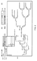
図1は、本発明のいくつかの実施形態において、ユニットプロセス(動作中心型)モデルを、構築、校正及びオンラインで配備するように構成されたコンピュータシステム100を示すブロック図である。コンピュータシステム100は、産業プラント及び化学プラント等のプラントのネットワークインフラストラクチャ内で構成されている。コンピュータシステム100は、モデル変換手段140、モデル校正手段150及び配備エンジン160を実行するように構成された少なくとも1つのコンピュータ(例えば、アプリケーションサーバ等)を含む。コンピュータシステム100は、さらに、ディスプレイ装置上に構成されたユーザインターフェース(例えば、グラフィカルなユーザインターフェース等)110、およびデータサーバ135に接続された集中データストア(データベース)130を含む。前記コンピュータシステムは、さらに、前記プラントでの動作ユニットを物理的に測定及び制御する計器装置180A〜180I(例えば、センサ、メータ、プローブ、バルブ、アクチュエータ、ゲージ、ヒータ等)と通信可能に接続されている計測制御操業コンピュータ175で構成された、分散制御システム170を備える。ユーザインターフェース110、(データサーバ135を介して)集中データストア130、モデル変換手段140、モデル校正手段150、配備エンジン160および分散制御システム175は、コンピュータシステム100内においてプラントネットワーク120によって通信可能に接続されている。
[System to build, calibrate and deploy unit process models]
FIG. 1 is a block diagram that illustrates a
コンピュータシステム100は、産業プラント及び化学プラント等のプラントでの物理的な(実際の)動作ユニットに関するリアルタイムの意思決定を促すユニットプロセスモデルを、動的に構築、校正及びオンラインで配備するように構成されている。コンピュータシステム100のモデル変換手段140は、そのオンラインのユニットプロセスモデルをプラントワイドプロセスモデル(ソースモデル)から構築する。当該ソースモデルは、プラントワイド操業の第一原理プロセスモデルであってもよい。前記ユニットプロセスモデルを構築するために、モデル変換手段140が、ソースモデルを選択するためのオプションを(プラントネットワーク120を介して)ユーザインターフェース110上でユーザに対して表示する。例えば、モデル変換手段140はユーザインターフェース110上に、ユーザがソースモデルを指定するためのフィールドを提示してもよい。他の例として、モデル変換手段140は、集中データストア130又はプラントネットワーク120内の別の到達可能な場所にクエリすることによってソースモデルのリストを取り出してもよい。そして、モデル変換手段140はユーザインターフェース110上でソースモデルのそのリストを、ユーザが当該ソースモデルのうちの一つを選択することを可能にする形式で表示してもよい。選択された当該ソースモデルは、フローシートの形態のような、モデル化されたプロセスのユニット動作ならびに当該ユニット動作間の材料、エネルギー及び情報の流れを含む構造化された形式で構成されたものであってもよい。
The
ユーザがソースモデルを選択した後、モデル変換手段140はユーザインターフェース110上でユーザに対して、そのソースモデルに含まれる例えば蒸留塔、熱交換器、反応器等のモデル化された動作ユニット(ユニット動作)を表示する。モデル化された各動作ユニットは、前記プラントでの物理的な動作ユニットに対応する。これを行うために、モデル変換手段140は、集中データストア130又はプラントネットワーク120内の別の到達可能な場所から、選択された前記ソースモデルを読み出してもよい。そして、モデル変換手段140は、ユーザインターフェース110上で、この読み出されたソースモデルの前記モデル化された動作ユニットを、ユーザが対象の動作ユニットを選択することを可能にする形式で表示してもよい。モデル変換手段140は、また、ユーザインターフェース110上で、前記読み出されたソースモデル内の動作ユニットを、グラフィカルな表現、リスト表現およびスプレッドシート表現等のユニット動作間の従属関係を表した表現で表示してもよい。
After the user has selected a source model, the model conversion means 140 sends to the user on the user interface 110 a modeled operating unit (unit such as a distillation column, a heat exchanger, a reactor, etc.) included in the source model. Display the operation). Each modeled operating unit corresponds to a physical operating unit in the plant. To do this, the model transformation means 140 may retrieve the selected source model from the
ユーザがユニット動作を選択すると、モデル変換手段140は前記ソースモデルを、選択された前記モデル化された動作ユニットのユニットプロセス(動作中心型)モデルに変換する。モデル変換手段140はユーザインターフェース110上で、変換される前記ユニットプロセスモデルを、ユーザが主要プロセス変数(例えば、操作変数、出力変数等)を前記選択されたモデル化された動作ユニットについての計器タグにマッピングすることを可能にする形式で表示する。モデル変換手段140はユーザインターフェース110上で、さらに、前記変換されるユニットプロセスモデルを、ユーザが前記選択されたモデル化された動作ユニットの動作目的を示す制御ループを当該ユニットプロセスモデルにおいて構成することを可能にする形式で表示する。そして、モデル変換手段140は、構造化された前記変換されたユニットプロセスモデルをコンピュータメモリに(例えば、構成ファイル等に)記憶する。例えば、モデル変換手段140は前記変換されたユニットプロセスモデルを、集中データストア130又はプラントネットワーク120内の別の到達可能な場所に構成ファイルとして記憶してもよい。
When the user selects a unit operation, the
前記ユニットプロセスモデルが構築されると、モデル校正手段150が当該ユニットプロセスモデルを校正する。この校正を実行するために、モデル校正手段150のデータセット生成部が、まず、前記ユニットプロセスモデルを調和させるのに用いられる校正データセットを生成する。前記データセット生成部はユーザインターフェース110上でユーザに対して、前記データセット用の時間ホライズンを校正するためのオプションを提示する。そして、前記データセット生成部は、(集中データストア130又はプラントネットワーク120上の別の場所に位置した)リアルタイムプラントヒストリアンから、校正された前記時間ホライズンにおけるプラントデータを取り出す。(モデル校正手段150の)前記データセット生成部は、マッピングされた前記計器タグに対応するプラントデータを取り出し、取り出された当該プラントデータのうちの、プラントプロセスの定常状態挙動を表すサブセットを、前記校正データセットとして選択する。
When the unit process model is constructed, the model calibration means 150 calibrates the unit process model. To perform this calibration, the data set generator of the model calibration means 150 first generates a calibration data set which is used to reconcile the unit process model. The data set generator presents the user on the
そして、モデル校正手段150の流量調和部が、生成された前記データセットを用いて、モデル化された流量を調和させる。前記流量調和部は、前記モデル化された動作ユニットに入る製品ストリーム(製品物流)をモデル化するための流量オフセット(校正パラメータ)を算出する。算出される当該流量オフセットは、前記プラントでの前記物理的な動作ユニットの流量計器(例えば、180A〜180Eのうちの少なくとも1つ等)による流量測定値と前記ユニットプロセスモデルにより算出された流量値との差分を定めたものである。同様に、モデル校正手段150の温度調和部が、生成された前記データセットを用いて、モデル化された温度を調和させる。前記モデル化された動作ユニットが蒸留塔である例では、前記温度調和部が、当該モデル化された動作ユニットの効率パラメータ及び通気パラメータを含む校正パラメータを算出する。効率パラメータは、前記プラントでの物理的な前記蒸留塔の計器(例えば、180A〜180Eのうちの少なくとも1つ等)により測定された温度と前記ユニットプロセスモデルにより算出された温度値との分離度を表す。通気パラメータは、前記プラントにおける前記蒸留塔での測定された圧力降下が前記ユニットプロセスモデルにより算出された圧力降下と合致するか否かを表す。前記モデル化された流量及び温度を調和させることにより前記ユニットプロセスモデルは、前記プラントでの前記物理的な動作ユニットの物理的な流量計器及び温度計器(例えば、180A〜180Eのうちの少なくとも1つ等)により収集された測定値を用いて、定常状態で機能することが可能となる。 Then, the flow rate matching unit of the model calibration means 150 uses the generated data set to match the modeled flow rate. The flow rate adjustment unit calculates a flow rate offset (calibration parameter) for modeling a product stream (product distribution) entering the modeled operation unit. The flow rate offset to be calculated is the flow rate measured value by the flow rate meter (for example, at least one of 180A to 180E, etc.) of the physical operation unit in the plant and the flow rate value calculated by the unit process model And the difference between Similarly, the temperature harmonization unit of the model calibration means 150 harmonizes the modeled temperature using the generated data set. In an example in which the modeled operating unit is a distillation column, the temperature harmony unit calculates calibration parameters including efficiency parameters and aeration parameters of the modeled operating unit. The efficiency parameter is the degree of separation between the temperature measured by the instrument (for example, at least one of 180A to 180E, etc.) of the physical distillation column at the plant and the temperature value calculated by the unit process model Represents The aeration parameters represent whether the measured pressure drop at the distillation column in the plant matches the pressure drop calculated by the unit process model. By reconciling the modeled flow rates and temperatures, the unit process model may include at least one of physical flow rate meters and temperature gauges (eg, 180A-180E) of the physical operating unit at the plant. Etc.) can be used in steady state.
次に、モデル校正手段150の原料推定手段構築部が、(前記ユニットプロセスモデルによりモデル化された)前記物理的な動作ユニットに入る原料ストリームの組成を推定する原料推定手段を構築する。当該原料推定手段構築部は、前記ユニットプロセスモデルについて生成された前記校正データセットを推定された原料組成で更新し、かつ、更新された当該データセットを用いて前記ユニットプロセスモデル(の流量及び温度)を再調和させる。前記動作ユニットが蒸留塔(又は同様のユニット)である場合には、次に、モデル校正手段150の流体力学的モデル調整部が、当該蒸留塔の各段での液体・蒸気往来を表現する。当該流体力学的モデル調整部は、前記蒸留塔内の所与の段が動作しているゾーン(例えば、安定動作ゾーン、不安定動作ゾーン、問題動作ゾーン等)を流体力学的モデルが正確に予測することを可能にする、調節可能なパラメータ(例えば、システムフォーム(foam)ファクタ等)についての数値を算出する。モデル校正手段150は、集中データストア130又はプラントネットワーク120内の別の到達可能な場所における前記変換されたユニットプロセスモデルの記憶された前記構成ファイルを、これらの校正パラメータによって更新してもよい。
Next, the raw material estimation means construction unit of the model calibration means 150 constructs a raw material estimation means for estimating the composition of the raw material stream entering the physical operation unit (modeled by the unit process model). The raw material estimation means construction unit updates the calibration data set generated for the unit process model with the estimated raw material composition, and uses the updated data set to calculate the flow rate and temperature of the unit process model. Rebalance). When the operation unit is a distillation column (or similar unit), next, the hydrodynamic model adjustment unit of the model calibration means 150 represents liquid / vapor traffic in each stage of the distillation column. The hydrodynamic model adjustment unit allows the hydrodynamic model to accurately predict the zone (e.g., stable operation zone, unstable operation zone, problem operation zone, etc.) in which the given stage in the distillation column is operating. Calculate numerical values for adjustable parameters (eg, system foam factor, etc.) that allow you to The model calibration means 150 may update the stored configuration file of the transformed unit process model at the
前記ユニットプロセスモデルが校正されると、配備エンジン160が当該ユニットプロセスモデルをオンラインで配備する。これを行うために、配備エンジン160は、校正された前記ユニットプロセスモデルを記憶した前記構成ファイルを読み出し、当該構成ファイルをリアルタイムプラントデータと関連付けて前記モデルをオンラインで動的に実行する。配備エンジン160はそのリアルタイムプラントデータを、(データサーバ135を介して)集中データストア130、又はプラントネットワーク120上の別の場所に位置した前記リアルタイムプラントヒストリアンから取り出す。前記リアルタイムプラントデータは、計測制御操業コンピュータ175によってプラントネットワーク120の物理的な計器(例えば、180A〜180Iのサブセット等)からリアルタイムで収集されて、配備エンジン160で設定された前記コンピュータのような他のプラントコンピュータにより取り出されることが可能であるように、前記リアルタイムプラントヒストリアンに書き込まれる。配備エンジン160は前記オンラインのユニットプロセスモデルを、リンクさせるために、前記取り出されたリアルタイムプラントデータに関連付け、当該オンラインのユニットプロセスモデルの解を求めることにより、対象のKPIの数値を算出する。当該数値は、リアルタイムプラントヒストリアン130に書き込まれる。計測制御操業コンピュータ175のようなプラントコンピュータが、前記リアルタイムプラントヒストリアン130からのKPI値にアクセスして、前記モデル化された動作ユニットの動作のリアルタイムの監視及び予測分析を実行してもよい。計測制御操業コンピュータ175は、この監視及び予測分析に基づいてプラント計器(例えば、180A〜180Iのサブセット等)を、前記プラントの前記モデル化された動作ユニット又は他の動作ユニットの動作を最適化又は制御する設定にプログラムしてもよい。計測制御操業コンピュータ175は、また、ユーザインターフェース110を介して、プラントオペレータなどのプラント従事者に、前記プラントの前記モデル化された動作ユニットのような動作ユニットの動作を最適化又は制御するための行動を取れるように、前記監視及び予測分析についてのデータを提供してもよい。
When the unit process model is calibrated, the
[例示的なユーザインターフェース画面]
図2〜図4は、本発明の実施形態において用いられる例示的なユーザインターフェース画面200〜400を示す概略図である。モデル変換手段140は、ユニットプロセスモデルを構築するプロセスの一部として、例示的なユーザインターフェース画面200〜400をユーザに表示してもよい。図2に、ソースモデル(プラントワイド第一原理プロセスモデル)からユニットプロセス第一原理モデルを生成するための例示的なユーザインターフェース画面200を示す。例示的なユーザインターフェース画面200によって、ユーザは、前記ユニットプロセスモデルの名前205を入力でき、当該ユニットプロセスモデルに関する説明220を入力できる。例示的なユーザインターフェース画面200によって、さらに、前記ユニットプロセスモデルに変換したいソースモデル210をユーザは選択できる。例示的なユーザインターフェース画面200は、選択されたソースモデル230をグラフィカルに表示する。この選択されたソースモデル230は、その動作ユニット235,240,245など、ならびに当該動作ユニット235,240,245など間の材料、エネルギー及び情報の流れを表示することを含む。
Exemplary User Interface Screen
2-4 are schematic diagrams illustrating exemplary user interface screens 200-400 used in embodiments of the present invention. The model transformation means 140 may display the exemplary user interface screens 200-400 to the user as part of the process of building a unit process model. FIG. 2 illustrates an exemplary
ユーザは、前記ユニットプロセスモデルに変換したい前記表示されたソースモデル230の、前記表示された動作ユニット235,240,245などのうちの一つを選択してもよい。これを行うために、ユーザは、その動作ユニットに付随するラベル(例えば、T−C1、T−C2、T−C3等)をドロップダウンリスト215から選択する。例えば、図2においてユーザは、ドロップダウンリスト215から、蒸留塔動作ユニットに付随するラベルT−C3を選択する。ユーザインターフェース画面200は、ユーザに対して、選択された前記ラベルに関連する前記選択された動作ユニットに対応する機器名225を表示する。例示的なユーザインターフェース画面200は、選択された前記モデル化された動作ユニットについてのユニットプロセスモデルへの前記ソースモデルの変換をユーザが開始するための、例えばボタンのようなグラフィカルな選択手段等のオプション(図示せず)を提示する。
The user may select one of the displayed operating
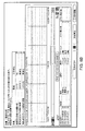
図3に、生成された前記ユニットプロセスモデルにおける前記動作ユニットの主要プロセス変数(操作変数及び出力変数)に計器タグをマッピングするための例示的なユーザインターフェース画面300を示す。図3に示すように、例示的なユーザインターフェース画面300は、ユーザに対して、前記ユニットプロセスモデル内に表示された前記蒸留塔動作ユニットの主要操作変数(塔圧力、原料流量[すなわち、図3の「TC2SF流量」]、生成物流量[すなわち、図3の「蒸気留分流量」及び「液体留分流量」]など)を提示する。例示的なユーザインターフェース画面300は、ユーザに対してさらに、計器タグ(PU−8706、FU−8610など)を提示する。ユーザは、当該計器タグをドラッグすることによって前記操作変数にマッピングしてもよい。
FIG. 3 shows an exemplary
図4に、生成された前記ユニットプロセスモデルにおける前記動作ユニットに制御ループをマッピングするための例示的なユーザインターフェース画面400を示す。図4に示すように、例示的なユーザインターフェース画面400は、ユーザに対して、前記ユニットプロセスモデル内に表示された前記蒸留塔動作ユニットの制御ループ(生成物組成、トレイ温度[すなわち、図4の「塔頂製品組成」及び「塔底製品組成」]など)を提示する。当該制御ループは、前記動作ユニットの一対のプロセス変数(操作変数及び制御変数)により決まる。例示的なユーザインターフェース画面400は、ユーザに対してさらに、計器タグ(PU−8706、FU−8610など)を提示する。ユーザは、当該計器タグをドラッグすることにより、前記制御ループを前記モデル化された動作ユニットの動作目的にマッピングしてもよい。
FIG. 4 illustrates an exemplary
[ユニットプロセスモデルを構築する方法]
図5は、本発明の実施形態においてユニットプロセスモデルを構築する、コンピュータに実装される方法500を示すフロー図である。一部の実施形態では、図1のモデル変換手段140が方法500を実行することにより、前記ユニットプロセスモデルを構築する。方法500は、ステップ510にて開始する。
[How to build a unit process model]
FIG. 5 is a flow diagram illustrating a computer-implemented
方法500はステップ520にて、産業プラント及び化学プラント等のプラントについてのプロセスモデル(ソースモデル)を選択する。一部の実施形態において、方法500(ステップ520)によって、人間つまりシステムユーザは、ユーザインターフェース110を介して前記ソースモデルを選択できる。他の実施形態では、方法500(ステップ520)が、プログラムされた条件、集中データストア130からアクセスされたパラメータ、またはプラントネットワーク120内の動作装置(例えば、図1の175、108A〜108I等)との通信に基づいて、前記ソースモデルを自動的に選択してもよい。選択された前記ソースモデルは、プラント操業の設計や評価などのオフライン用途のために作成及び構成された、(広範なプラントプロセス範囲を包含する)第一原理モデルである。選択された前記モデルは、モデル化されたプラントプロセスの動作ユニット(例えば、蒸留塔等)、ならびに当該動作ユニット間の材料、エネルギー及び情報の流れを含む。一部の実施形態では、前記プロセスモデルが、プラントプロセスの主要(メジャーな)動作ユニットのみを含んでもよい。
方法500はステップ530にて、前記ソースモデル内に含まれる、モデル化された動作ユニットを特定する。モデル化された各動作ユニットは、プラントでの物理的な動作ユニットに相当する。例えば、方法500(ステップ530)は、集中データストア130又はプラントネットワーク120上の別の到達可能な場所からの、選択された前記ソースモデルにアクセスして、当該モデルの動作ユニットを特定してもよい。そして、方法500(ステップ530)は、アクセスされた前記ソースモデルを、読み出し、パースし、検索し、又は処理し、選択された当該ソースモデルの、前記モデル化された動作ユニット及び対応する情報を特定してもよい。一部の実施形態では、方法500(ステップ530)がユーザインターフェース110上でユーザに対して、前記動作ユニットを、モデル化された当該動作ユニットの少なくとも一つを選択するためのオプションと共に表示してもよい。例えば、モデル変換手段140がユーザに対して、前記モデル化された動作ユニットを、(例えば、図2に示すように)前記ソースモデルのグラフィカルな表現内、リスト表現、およびフローシート表現などの、特に制限のない任意の構造化された表現で提示してもよい。
The
方法500はステップ540にて、特定された前記モデル化された動作ユニットから対象のモデル化された動作ユニットを選択する。一部の実施形態では、人間つまりシステムユーザが、ユーザインターフェース110上のオプション(例えば、図2の215等)を用いて当該モデル化された動作ユニットを選択してもよい。他の実施形態では、方法500(ステップ540)が、プログラムされた条件、集中データストア130に記憶されたパラメータ、またはプラントネットワーク120内での動作装置(例えば、図1の175、108A〜108I等)との通信に基づいて、前記モデル化された動作ユニットを自動的に選択してもよい。方法500(ステップ540)が対象の動作ユニットを選択すると、当該方法500はステップ550にて、選択された当該モデル化された動作ユニットについての、オフラインバージョンのユニットプロセスモデルを生成する。
The
方法500はステップ550にて、(広範なプラント範囲の)前記ソースモデルを、選択された前記モデル化された動作ユニットのみに集中した(つまりこの動作ユニットを中心とする)モデルに変換することにより、オフラインのユニットプロセスモデルを生成する。この変換を実行するために、方法500(ステップ550)が、まず、選択された前記モデル化された動作ユニットとは直接関連しない情報を前記モデルから取り除くことにより、前記ソースモデルの範囲を当該選択されたモデル化された動作ユニットの範囲(レベル)に自動的に減少させる。例えば、前記プロセスに動作ユニットが複数存在している場合には、方法500(ステップ550)が、モデル化された他の動作ユニットに関係する(すなわち、選択された前記モデル化された動作ユニットとは無関係の)全ての情報(プロセス変数および式など)を除外する。方法500(ステップ550)は、次に、選択された前記モデル化された動作ユニットについての既存の仕様を当該モデル化された動作ユニットについての標準仕様のセットに自動的に置き換える。置き換えられる仕様は、設計、操業、圧力および効率などの、選択された当該モデル化された動作ユニットについての任意のこのような標準仕様を含んでもよい。方法500(ステップ550)は、さらに、前記ソースモデルにおける計算基準を標準計算形式に変換する。例えば、前記ソースモデルがモル又は体積単位で構成されている場合には方法500(ステップ550)が、当該モデルを質量単位に自動的に変換する。選択された前記モデル化された動作ユニットについての前記標準仕様及び標準計算形式は、集中データストア130又はプラントネットワーク120上の他の場所から取り出されてもよい。選択された前記動作ユニットが蒸留塔である場合には、方法500(ステップ550)が、さらに、前記ユニットプロセスモデルにおいて塔の内部の部位(校正変数)を生成して、当該モデルの正確な校正を支援する。
方法500はステップ560にて、計器(生産)タグを前記ユニットプロセスモデルの主要プロセス変数にマッピングする。他の実施形態では、前記モデル化された動作ユニットの計器(構成要素)を前記ユニットプロセスモデルにおける主要プロセス変数にマッピングするのに、他の方法が用いられてもよい。マッピングを行うために、方法500(ステップ560)は、生成された前記ユニットプロセスモデルから、前記動作ユニットについての主要プロセス変数を取り出す。これらのプロセス変数は、操作変数(MV)と出力変数(OV)という2種類のプロセス変数を含む。MVは、前記ユニットプロセスモデルの解を求めるのに設定される必要がある入力変数である。OVは、前記物理的な動作ユニットの計器により得られた測定値に基づいて算出される、前記ユニットプロセスモデルの出力変数である。OVは、前記モデル化された動作ユニットの物質収支を算出するのに用いられる出力ストリーム流量変数、前記モデルが実際の(物理的な)プラント操業の正確な表現であるか否かを判定するのに有用な出力トレイ温度変数などを含み得る。方法500(ステップ560)は、さらに、(例えば、集中データストア130における)プラントデータヒストリアンから前記モデル化された動作ユニットについての計器タグを取り出し、これら計器タグを、取り出された前記主要プロセス変数にマッピングする。一部の実施形態では、方法500(ステップ560)が、ユーザインターフェース110上でユーザに対して、取り出された前記計器タグ及びプロセス変数を提示し、これにより、ユーザは、(例えば、図3に示すように)当該計器タグを当該プロセス変数に位置付け(例えば、ドラッグ)できる。
The
方法500(ステップ560)が計器タグのこれらのマッピングを実行する理由は、前記ユニットプロセスモデルの構成を育て上げるのに用いられる前記ソースモデルがしばしば理論ベースで作成されているからである。つまり、方法500(ステップ560)は、前記ユニットプロセスモデルをプラントでの前記動作ユニットの実際の物理的構成と整合させるために、計器タグのマッピングを実行する。前記ソースモデルが実際に作成されたものである場合には、前記ユニットプロセスモデルが実際の(物理的な)動作ユニット構成と既に整合しているので、方法500はステップ560を省略してもよい。
The reason that the method 500 (step 560) performs these mappings of instrument tags is that the source model used to develop the unit process model configuration is often created on a theoretical basis. That is, method 500 (step 560) performs instrument tag mapping to match the unit process model with the actual physical configuration of the operating unit at the plant. If the source model is actually created, then the
方法500はステップ570にて、前記ユニットプロセスモデルの前記モデル化された動作ユニットについての動作目的を指定する。これを行うために、方法500(ステップ570)は、計器(生産)タグを、前記モデル化された動作ユニットの動作目的を示す制御ループにマッピングする。他の実施形態では、前記モデル化された動作ユニットの計器(構成要素)を前記ユニットプロセスモデルにおける制御ループにマッピングするのに、他の方法が用いられてもよい。各制御ループは、MVと制御変数(CV)という一対の変数により決まる。方法500(ステップ560)は、前記モデル化された動作ユニットについての制御ループの標準セットを生成する。方法500は、さらに、(例えば、集中データストア130における)プラントデータヒストリアンから前記モデル化された動作ユニットについての計器タグを取り出し、これらの計器タグを、生成された前記制御ループにマッピングする。これらの計器タグのマッピングは、プラントにおける実際の動作ユニットにどの制御ループが存在しているのかを特定して、当該モデル化された動作ユニットの動作目的を示す。一部の実施形態では、方法500(ステップ560)が、ユーザインターフェース110上でユーザに対して、取り出された前記計器タグ及び制御ループを提示し、これにより、ユーザは、(例えば、図4に示すように)当該計器タグを当該制御ループに位置付け(例えば、ドラッグ)できる。
The
方法500はステップ580にて、(マッピングされたプロセス変数及び制御ループを含め)生成された前記ユニットプロセスモデルを、プラントネットワーク120上の(例えば、集中データストア130における)メモリ内の構成ファイル(コンフィグレーションファイル)に保存する。前記ユニットプロセスモデルのこの保存されたバージョンは、オフラインバージョンと称される。前記ユニットプロセスモデルを構築する方法500は、ステップ590にて終了する。
The
[ユニットプロセスモデルを校正する方法]
図6Aは、本発明の実施形態においてユニットプロセスモデルを校正する、コンピュータに実装される方法600を示すフロー図である。方法600は、図5の方法500により生成された前記ユニットプロセスモデルを校正するのに用いられてもよい。一部の実施形態では、図1のモデル校正手段150が方法600を実行することにより、前記ユニットプロセスモデルを構築する。図6Aの実施形態では、前記ユニットプロセスモデルが第一原理モデルである。方法600は、前記ユニットプロセスモデルをオンラインで機能するように校正して、プラントにおいて前記モデル化された動作ユニットに関するリアルタイムの意思決定を促す。方法600は、当該校正の一部として、前記ユニットプロセスモデルのコンポーネンを調和させて、プラントでの物理的な計器装置(例えば、図1の108A〜108I等)からリアルタイムで収集された測定値を用いて当該モデルがオンラインで機能することを可能にする。これにより、調和された前記ユニットプロセスモデルは、プラントでの前記動作ユニットに関するプラント操業を正確に監視及び予測することが可能となる。さらに、このオンラインモデルは、前記モデル化された動作ユニットについてのリアルタイムの正確な予測分析を、プラント制御システム(例えば、図1のコンピュータ175等)やプラント従事者(例えば、プラントエンジニアおよびオペレータ等)に出力することが可能となる。
[How to calibrate a unit process model]
FIG. 6A is a flow diagram illustrating a computer-implemented
[モデルデータセットの生成]
方法600は、ステップ605にて開始する。方法600はステップ610にて、ユニットプロセスモデルについての前記構成ファイルを読み出す。一部の実施形形態では、当該ユニットプロセスモデルは方法500により生成されたものであり、当該構成ファイルは方法500のステップ580で保存されたものである。方法600はステップ615にて、前記ユニットプロセスモデルによりモデル化された前記動作ユニットに入る原料ストリームのベース原料組成を読み出す(初期化する)。方法600(ステップ615)は、前記ユニットプロセスモデルを(図5を参照しながら説明したように)構築するのに用いられた前記ソースモデルから、前記モデル化された動作ユニットのベース原料組成を読み出してもよい。方法600(ステップ615)は、前記モデル化された動作ユニットの各主要成分についての原料組成範囲を、前記ベース原料組成を基準とする割合で算出してもよい。
Generate Model Dataset
方法600はステップ620にて、前記リアルタイムプラントヒストリアンから、前記ユニットプロセスモデルを校正するためのプラントデータを取り出す。前記リアルタイムプラントヒストリアンは、集中データストア130又はプラントネットワーク120上の別の場所に位置してもよい。方法600(ステップ620)は、当該プラントヒストリアンにクエリして当該プラントヒストリアンから、前記ユニットプロセスモデルに(ステップ560〜ステップ570で)マッピングされた前記計器タグに対応するプラントデータを取り出す。方法600(ステップ620)は、当該プラントヒストリアンから、校正された時間ホライズン(例えば、ユーザインターフェース110でユーザにより選択された時間ホライズン等)の前記プラントデータを取り出す。方法600(ステップ620)は、さらに、取り出された前記プラントデータから、前記動作ユニットの各MVの最大値及び最小値(数値範囲)を決定する。
The
方法600はステップ625にて、前記ユニットプロセスモデルを調和させるのに用いられるデータセットを生成する。一部の実施形態では、モデル校正手段150のデータセット生成部が、方法600のステップ610〜ステップ625を実行してもよい。有用なデータセットを生成するには、方法(ステップ625)が、まず、前記プラントヒストリアンから取り出された(ステップ620)、校正された前記時間ホライズンの前記プラントデータを適応させる。一部の実施形態では、方法600(ステップ625)が、内挿を実行して前記プラントデータを適応させる。当該内挿によって、前記プラントヒストリアンにクエリしてそのプラントヒストリアンから取り出された、まさにその前記時間ホライズン(タイムスタンプ)にわたるプラントデータの制御が可能になる。そして、方法600(ステップ625)は、内挿された前記プラントデータに対してローリング平均を実行して前記データセットを生成する。生成された当該データセットは、方法600の後続のステップにおいて、定常状態領域の決定とモデルの生成との両方に利用されてもよい。
The
方法600(ステップ625)は、適応させられた前記プラントデータの各データ点ごとに、前記ユニットプロセスモデルにおける前記動作ユニットの物質収支及びその物質収支誤差(MBE)を算出する。方法600(ステップ625)は、当該物質収支を、全ての出口流量の合計から入口流量の合計を引いたものとして算出し、当該MBEを、入口流量の合計で前記物質収支を正規化したものとして算出する。そして、方法600(ステップ625)は、校正された前記時間ホライズン(校正窓)内の定常状態挙動の時間領域を特定する。図6Bに示すように、方法600(ステップ625)は、当該校正窓にわたって前記物質収支誤差の統計を調べる。方法600は、前記構成窓における各データ点について、当該データ点の前記物質収支誤差が物質収支平均と偏差とにより定まる定常状態バンド内に収まる場合には当該データ点を、定常状態クラスタ内に存在する可能性があるものとして分類する。前記時間ホライズン窓のある時間領域が定常状態クラスタとして見なされるには、当該時間領域が、平均MBE−MBEの標準偏差<MBE<平均MBE+MBEの標準偏差に収まるMBEを有する連続するn個(nは、設定可能なパラメータである)のデータ点を含んでいる必要がある。そして、方法600(ステップ625)は、前記データ点のうちの、特定された前記定常状態領域内に存在するサブセット(システム設定可能なパラメータ)を選択して、前記データセットを生成する。これらのデータ点は、連続する最も長い定常状態時間領域に最も高いサンプリング優先度が与えられるようにしたうえで、サンプリングされる定常状態領域の数が最大になるように選択される。
Method 600 (step 625) calculates, for each data point of the adapted plant data, the mass balance of the operating unit in the unit process model and its mass balance error (MBE). Method 600 (step 625) calculates the mass balance as the sum of all outlet flow rates minus the sum of inlet flow rates, and the MBE as the mass balance normalized by the total inlet flow rates calculate. The method 600 (step 625) then identifies the time domain of steady state behavior within the calibrated time horizon (calibration window). As shown in FIG. 6B, method 600 (step 625) examines the statistics of the mass balance error over the calibration window. The
[流量の調和]
方法600はステップ630にて、生成された前記データセットを用いて、前記ユニットプロセスモデルにおける前記モデル化された流量を調和させる。当該調和により、前記ユニットプロセスモデルは、プラントでの前記モデル化された動作ユニット(又は他の動作ユニット)の物理的な流量計器によりリアルタイムで収集された測定値を用いて機能する(駆動される)ことが可能となる。一部の実施形態では、モデル校正手段150の流量調和部がステップ630を実行してもよい。前記ユニットプロセス(第一原理)モデルの流量調和は、プラントシステムが定常状態にあるときの前記モデル化された動作ユニットの正確なプロキシ(代理)として当該モデルが使用されることが可能となるように、当該モデルについての校正パラメータを算出することを伴う。流量調和用の校正パラメータは、前記動作ユニットに入る製品ストリームの流量オフセットである。流量オフセットは、プラントでの前記動作ユニットの物理的な流量計器により測定された流量値と前記ユニットプロセスモデルにより算出された流量値との差分(すなわち、流量オフセット値=観測プラント値−モデル予測値)である。方法600(ステップ630)が流量調和を実行するには、これらの製品ストリームの原料組成が判明している必要がある。しかし、原料組成を算出するには原料推定手段が必要になるのに対して、原料推定手段は、調和されたユニットプロセス(第一原理)モデルが既に利用可能である場合にしか構築されることができない。方法600が、流量調和を実行する前に(ステップ615で)前記ソースモデルからの原料組成を初期化していたのは、流量調和と原料推定手段の構築との依存関係に対処するためである。
[Harmonization of flow rate]
The
流量調和用の校正パラメータ(流量オフセット)を算出するために、方法600(ステップ630)は、ステップ625で生成された前記データセットの前記データ点をトレーニングセットとテストセットとに、前記校正窓にわたってテスト点及びトレーニング点の範囲が最大になるように分ける(分類する)。方法600(ステップ630)は、ステップ625で決定された前記定常状態クラスタの種類(バリエーション)を最大化する定常状態検出手段を用いて、前記範囲を最大にしてもよい。当該定常状態検出手段は、理想的には:(1)前記モデルの校正に用いられる固有の定常状態の数を最大化する;及び(2)前記構成窓の全体にわたる定常状態クラスタを提供する;ものであるのが望ましい。方法600(ステップ630)は、本発明の実施形態において定常状態検出手段を論理的に改良している。これを行うために、方法600(ステップ630)は、定常状態点間の距離に基づいた定常状態クラスタ選択を優先する。実施形態では、トレーニング点として使用される点の割合が、システム設定パラメータ(システムコンフィグレーションパラメータ)である。
To calculate a calibration parameter (flow offset) for flow conditioning, the method 600 (step 630) generates the data points of the data set generated in
そして、方法600(ステップ630)は、前記モデル化された(物理的な)動作ユニットの前記流量計器での期待誤差を決定する。一部の実施形態では、ユーザが、ユーザインターフェース110を介して前記流量計器での前記期待誤差を設定してもよい。方法600(ステップ630)は、次に、決定された前記期待誤差を考慮しながら第一原理モデルを前記トレーニングセットにおける全ての点について生成し、当該第一原理モデルに関してプラント測定値とモデル変数との誤差が最小化される最適化計算の解を求める。生成された第一原理モデルの校正されるパラメータは、プラント変数とモデル変数との間の流量オフセット、および他の第一原理モデルパラメータ(例えば、蒸留塔モデルの場合には効率等)を含む。方法600(ステップ630)は、複数回のトレーニング実行にわたって前記最適化モデルの生成と解算出を繰り返す。方法600(ステップ630)は、全てのトレーニング実行にわたる各流量オフセットの平均値を算出し、前記校正パラメータを前記流量オフセットの当該算出された平均値に設定する。
The method 600 (step 630) then determines the expected error in the flow meter of the modeled (physical) operating unit. In some embodiments, a user may set the expected error in the flow meter via the
方法600(ステップ630)は、次に、決定された前記期待誤差を考慮しながらシミュレーションモデルを前記テストセットにおける全ての点について生成する。生成された当該シミュレーションモデルは、方法600のステップ630及びステップ635で見つかる前記校正されるパラメータを組み込んだものである。方法600は、さらに、生成された前記シミュレーションモデルの解を(前記校正パラメータを固定したうえで)求めて、前記校正パラメータ(平均流量オフセット)の品質を決定する。前記最適化モデルの生成および解算出は、複数回のテスト実行にわたって繰り返される。つまり、当該テスト実行は、前記トレーニング実行の完了後に実行されるものであるが、決定された前記校正パラメータ及び推定された品質を用いてデータ(モデル予測)を生成する。当該データは、実際のプラント値と共にユーザ(例えば、人間またはシステム等)に提示され、これにより、校正された前記モデルの品質を当該ユーザが判断してもよい。
The method 600 (step 630) then generates a simulation model for all points in the test set, taking into account the determined expected error. The generated simulation model incorporates the calibrated parameters found in
[温度の調和]
方法600はステップ635にて、生成された前記データセット(ステップ625)を用いて、前記ユニットプロセスモデルにおける前記モデル化された温度を調和させる。当該調和により、前記ユニットプロセスモデルは、プラントでの前記モデル化された動作ユニット(又は他の動作ユニット)の物理的な温度計器によりリアルタイムで収集された測定値を用いて機能する(駆動される)ことが可能となる。一部の実施形態では、モデル校正手段150の温度調和部がステップ635を実行してもよい。前記ユニットプロセス(第一原理)モデルの温度調和は、当該モデルの流量調和(ステップ630)と同様に、プラントシステムが定常状態にあるときの前記モデル化された動作ユニットの正確なプロキシ(代理)として当該モデルが使用されることが可能となるように、当該モデルについての校正パラメータを算出することを伴う。前記モデル化された動作ユニットが蒸留塔であるときの当該校正パラメータは、当該モデル化された動作ユニットについての効率パラメータ(変数)及び通気パラメータ(変数)である。方法600(ステップ635)は、前記効率パラメータを、プラント測定値とモデル予測との間の誤差を最小にする解設定時に計算エンジンによって動かされる自由度として設定する。
[Harmony of temperature]
The
方法600(ステップ635)は、算出された塔圧力降下がプラントにおける物理的な蒸留塔での測定された圧力降下と合致することを可能にする、前記通気パラメータについての数値を算出する。方法600(ステップ635)は、前記第一原理モデル内の計算を、まず、モデル予測された塔底段圧力とモデル予測された塔頂段圧力との差分を表す新たなモデル変数(すなわち、モデル予測される塔圧力降下変数)を導入することによって実行する。方法600(ステップ635)は、次に、前記通気パラメータの仕様を固定されたものから計算されたものに変更すると同時に、前記モデル予測される塔圧力降下変数の仕様を計算されたものから固定されたものに変更する。そして、方法600(ステップ635)は、前記モデル予測される塔圧力降下変数をプラントにおいて観測される圧力降下に等しくする。 Method 600 (step 635) calculates a numerical value for the vent parameter that allows the calculated tower pressure drop to match the measured pressure drop at a physical distillation column at the plant. Method 600 (step 635) first calculates the calculations in the first principle model as new model variables representing the difference between the model predicted bottom pressure and the model predicted top pressure (ie, the model It does this by introducing the expected tower pressure drop variable). The method 600 (step 635) may then modify the specification of the model predicted tower pressure drop variable from the calculated one while changing the specification of the aeration parameter from a fixed one to one calculated. Change to The method 600 (step 635) then makes the model predicted tower pressure drop variable equal to the pressure drop observed at the plant.
温度調和用の校正パラメータを算出するために、方法600(ステップ635)は、ステップ625で生成された前記データセットの前記データ点をトレーニングセットとテストセットとに分ける(分類する)。方法600(ステップ635)は、ステップ625で(図6Bに示すように)決定された定常状態クラスタの種類(バリエーション)を最大化する定常状態検出手段を用いて、前記範囲を最大にしてもよい。これを行うために、方法600(ステップ635)は、定常状態点間の距離に基づいた定常状態クラスタ選択を優先する。そして、方法600(ステップ635)は、前記モデル化された(物理的な)動作ユニットの前記温度計器での期待誤差を決定する。一部の実施形態では、ユーザが、ユーザインターフェース110を介して前記温度計器での前記期待誤差を設定してもよい。方法600(ステップ635)は、次に、決定された前記期待誤差を考慮しながら第一原理モデルを前記トレーニングセットにおける全ての点について生成する。そして、方法600(ステップ635)は、当該第一原理モデルに関してプラント測定値とモデル変数との間の誤差が最小化される最適化計算の解を求めて、(前記動作ユニットが蒸留塔である場合には)前記効率パラメータ及び通気パラメータを含む前記校正パラメータを決定する。方法600(ステップ635)は、複数回のトレーニング実行にわたって前記最適化モデルの生成と解算出を繰り返す。方法600(ステップ635)は、全てのトレーニング実行にわたる平均値を算出し、前記校正パラメータを当該算出された平均値に設定する。
To calculate calibration parameters for temperature matching, method 600 (step 635) separates (classifies) the data points of the data set generated in
方法600(ステップ635)は、次に、決定された前記期待誤差を考慮しながらシミュレーションモデルを前記テストセットにおける全ての点について生成する。方法600は、さらに、生成された前記シミュレーションモデルの解を求めて、前記校正パラメータの品質を決定する。前記最適化モデルの生成および解算出は、複数回のテスト実行にわたって繰り返される。つまり、当該テスト実行は、前記トレーニング実行の完了後に実行されるものであるが、決定された前記校正パラメータを用いることにより、前記最適化モデルからの結果の品質を推定する。前記最適化モデルの生成および解算出は、複数回のテスト実行にわたって繰り返される。つまり、当該テスト実行は、前記トレーニング実行の完了後に実行されるものであるが、決定された前記校正パラメータ及び推定された品質を用いてデータ(モデル予測)を生成する。当該データは、実際のプラント値と共にユーザ(例えば、人間またはシステム等)に提示され、これにより、校正された前記モデルの品質を当該ユーザが判断してもよい。
Method 600 (step 635) then generates a simulation model for all points in the test set, taking into account the determined expected error. The
[原料推定手段の構築]
方法600はステップ640にて、前記ユニットプロセスモデルにおいて原料推定手段を構築する。一部の実施形態では、モデル校正手段150の原料推定手段構築部がステップ640を実行してもよい。方法600(ステップ640)は、プラントでの(前記ユニットプロセスモデルによりモデル化された)前記物理的な動作ユニットに入る原料ストリームの組成を推定するために前記原料推定手段を構築する。方法600(ステップ640)は、(630〜635から出力された)調和された前記ユニットプロセスモデルを用いて、前記原料推定手段を構築するのに用いられる原料推定手段データセットを生成する。方法600(ステップ640)は、当該原料推定手段データセットを生成するのに:(i)ステップ615で決定された、動作ユニットの各主要成分についての前記原料組成範囲;及び(ii)ステップ620で決定された、校正された前記時間ホライズンにわたる前記動作ユニットの各MVの範囲;を用いる。
[Construction of raw material estimation means]
The
方法600のステップ640は、2種類のアルゴリズム(ソボル数列(Sobol Sequences)とランダムフォレスト(Random Forest))を新規な手法で組み合わせる。方法600(ステップ640)は、まず、ソボル数列生成アルゴリズムにより、超一様分布のソボル数の多次元単位立方体(立方体の次元は、原料組成変数及びMVからなる)の、構造化されていないサンプリング点の正規化された集合(セット)を生成する。例えば、S. Joe及びF. Y. KuoによるRemark on Algorithm 659: Implementing Sobol's quasirandom sequence generator(「ソボルの準乱数列生成器」), ACM Trans. Math. Softw. 29, 49-57 (2003)等を参照のこと(この全体は、参照をもって本明細書に取り入れたものとする)。さらに、例えば、http://web.maths.unsw.edu.au/~fkuo/sobol/ (2010)等も参照のこと(この全体は、参照をもって本明細書に取り入れたものとする)。方法600(ステップ640)の実施形態は、前記ソボル数列生成アルゴリズムにより、サンプリング点の最適又は略最適な配置を、選択される点の数にかかわらず提供する。
Step 640 of
そして、方法600(ステップ640)は、入力値のこの集合(セット)を用いて、ステップ630〜ステップ635で生成された前記調和されたユニットプロセス(第一原理)モデルの解を求める。方法600(ステップ640)は、上記で生成されたソボル数列の各動作点を入力値として用いて、ステップ630〜ステップ635で生成された前記調和されたユニットプロセス(第一原理)モデルの相異なるインスタンスの解を求めて、プロセスモデル予測される出力変数(OV)データのセットを収集する。当該OVは、ユーザによりマッピングされたプラント測定値のモデル予測に相当する。入力値及び出力値のこれらのセットが全体として、前記原料推定手段データセットを成す。これら入力値及び出力値のセットは、前記ユニットプロセスモデルについてのランダムフォレスト原料推定手段モデルを構築するのに用いられる。方法600は、さらに、ステップ645にて、前記原料推定手段データセットを用いて前記モデル化された動作ユニットの原料組成を推定する。
The method 600 (step 640) then uses this set of input values to solve for the harmonized unit process (first principles) model generated in steps 630-635. Method 600 (step 640) differs from the harmonized unit process (first principles) model generated in steps 630-635, using each operating point of the Sobol sequence generated above as an input value. Solve for the instance and collect a set of process model predicted output variable (OV) data. The OV corresponds to model prediction of plant measurement values mapped by the user. Together these sets of input values and output values make up the raw material estimator means data set. These sets of input and output values are used to construct a random forest raw material estimator model for the unit process model. The
方法600(ステップ645)は、前記ランダムフォレスト原料推定手段モデルを構築するために、ランダムフォレスト回帰子を呼び出す。例えば、http://scikit-learn.org/stable/modules/generated/sklearn.ensemble.RandomForestRegressor.html (2010)等を参照のこと。方法600は、ランダムフォレスト回帰子への入力を前記プロセスユニット動作モデルからの操作変数(MV)及び出力変数(OV)として、前記ランダムフォレストアルゴリズムのパラメータを例えばscikit-learn: machine learningin python, http ://dl.acm.org/citation.cfm?id=2078195 (2011)(この全体は、参照をもって本明細書に取り入れたものとする。)等に示すように算出してもよい。方法600(ステップ645)は、算出されたこれらのパラメータを用いて前記ランダムフォレストアルゴリズムを実行して、前記物理的な動作ユニットで読み取られた測定値に基づいて前記ユニットプロセスモデルの原料組成を推定する。これに関して、方法600は本質的に、超一様分布のソボル数が及ぶ空間にわたって、ステップ630〜ステップ635で生成された前記調和されたユニットプロセス(第一原理)モデルに対して逆関数を実行するものである。方法600は、推定された前記原料組成を用いて、ステップ625からの前記生成されたデータセットを更新する。方法600はステップ560にて、調和結果が未だ安定でないと判断すると、当該調和結果が安定するまで前記更新されたデータセットを用いてステップ630〜ステップ645を繰り返す。方法600(ステップ645、ステップ560)は、調和結果が安定していると当該方法600が判断すると、ステップ650に進む。
The method 600 (step 645) calls a random forest regressor to build the random forest material estimator means model. See, for example, http://scikit-learn.org/stable/modules/generated/sklearn.ensemble.RandomForestRegressor.html (2010). The
一部の実施形態において原料推定手段構築部は、原料組成の変化により直接影響を受ける、蒸留塔での利用可能な温度/圧力/アナライザセンサの数が、推定される原料成分の数よりも少なくなる原料組成に遭遇する場合があり得る。この状況では方法600(ステップ645)が、原料推定を実行する前に、類似した原料成分を一括化する(一様に扱う)。この一括化アプローチは、校正された前記ユニットプロセスモデルからの、原料成分値についてのセンサ値の偏微分を含む感度行列に対して、主成分分析(PCA)を実行する。当該PCA分析での原料成分間の距離が、類似度の定量評価となる。2種類の原料成分が極めて類似している場合には、これらの成分が一括化されるのが望ましい。一括化が完了すると、原料推定プロセスが実行可能となる。一括化された原料成分についての当該原料推定プロセスが完了すると、それらの成分の一括化が解除されて、前記ユニットプロセスモデルに元々存在していた比率に戻される。 In some embodiments, the feedstock estimation means construction unit has a smaller number of available temperature / pressure / analyzer sensors in the distillation column that is directly affected by changes in feedstock composition than the number of feedstock components estimated. There may be cases where the following raw material composition is encountered. In this situation, the method 600 (step 645) packages (uniformly treats) similar raw material components before performing raw material estimation. This integrated approach performs principal component analysis (PCA) on a sensitivity matrix that includes partial derivatives of sensor values for raw material component values from the calibrated unit process model. The distance between the raw material components in the PCA analysis is a quantitative evaluation of the degree of similarity. If the two source components are very similar, it is desirable that these components be packaged together. Once batching is complete, the raw material estimation process can be performed. When the raw material estimation process for the grouped raw material components is completed, the grouping of those components is canceled and returned to the ratio originally existing in the unit process model.
[流体力学的モデルの調整]
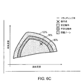
ユニットプロセスモデルが蒸留塔動作ユニットを表したものである場合には、方法600が、さらに、ステップ650にて、当該ユニットプロセスモデルの流体力学的モデルを調整する。一部の実施形態では、モデル校正手段150の流体力学的モデル調整部がステップ650を実行してもよい。前記流体力学的モデルは、前記蒸留塔の各段での液体・蒸気往来を表す。(前記ユニットプロセスモデルの一部としての)当該流体力学的モデルは、蒸留塔が飛沫同伴、フラッディング、またはウィーピングなどの動作上の問題に遭遇しているか否かを判定するように前記ユニットプロセスモデルにより用いられる。フラッディングリスクに関する塔動作の安定性は、十分確立されたフラッディング相関式(例えば、H.Z. Kister and J.R. Haas, Chem. Eng. Prog., 86(9), page 63 (1990)、J.R Fair, Petro/Chem Eng., 33(10), page 45 (1961)等を参照のこと。これらの全体は、参照をもって本明細書に取り入れたものとする。)により定量化されることができる。これらの相関式は、動作変数(例えば、トレイ蒸気流量及びトレイ液体流量等)ならびにパラメータ(例えば、システムフォーミング(foaming)ファクタ等)からフラッディング率(FF)を算出する。前記流体力学的モデルのフラッディング率の算出値に基づき、前記蒸留塔についての動作領域は、図6Cに示すように、安定動作ゾーン(FF<80%)と、不安定動作ゾーン(80%≦FF<90%)と、問題ゾーン(FF>90%:動作上の問題に遭遇する)という3種類の主なゾーンに分けられることができる。前記蒸留塔における所与の段の液体・蒸気流量は、前記3種類のゾーンのうちのどのゾーンで当該塔の所与の段が動作しているかを示す。
[Adjustment of hydrodynamic model]
If the unit process model is representative of a distillation column operating unit, then the
前記流体力学的モデルは複数の調節可能なパラメータ(例えば、システムフォーミングファクタ)を含み、方法600(ステップ650)はパラメータ調節によって当該流体力学的モデルを調整する。方法600(ステップ650)は、前記流体力学的モデルの例えばシステムフォーミングファクタ等の前記調節可能なパラメータについての数値を算出することにより、当該流体力学的モデルを調整する。方法600(ステップ650)は、前記蒸留塔内の所与の段が動作しているゾーンを前記流体力学的モデルが正確に予測することを可能にする、前記調節可能なパラメータについての数値を算出する。 The hydrodynamic model includes a plurality of adjustable parameters (eg, system forming factors), and the method 600 (step 650) adjusts the hydrodynamic model by parameter adjustment. The method 600 (step 650) adjusts the hydrodynamic model by calculating numerical values for the adjustable parameter of the hydrodynamic model, eg, system forming factor. Method 600 (step 650) calculates numerical values for the adjustable parameters that allow the hydrodynamic model to accurately predict the zone in which a given stage in the distillation column is operating. Do.
以下は、トレイ又は充填物(パッキング)からなる蒸留塔を表す前記ユニットプロセスモデルの流体力学的モデルを調整する方法600(ステップ650)により実行される例示的なステップである。方法600(ステップ650)は、まず、ステップ625からの前記生成されたデータセットにおける各点ごとに、ステップ630及びステップ635から出力された前記調和されたユニットプロセス(第一原理)モデルを用いて塔プロファイルを算出する。方法600(ステップ650)は、次に、校正された前記時間ホライズンにわたる塔圧力降下最大値及び対応するフラッディング率値を特定する。一部の実施形態では、これらの数値がユーザによりユーザインターフェース110を介して設定される。他の実施形態では、これらの数値が、ステップ630及びステップ635から出力された前記調和されたユニットプロセス(第一原理)モデルによる推定値として算出される。
The following are exemplary steps performed by the method 600 (step 650) of adjusting the hydrodynamic model of the unit process model representing a distillation column consisting of trays or packings. Method 600 (step 650) first uses, for each point in the generated data set from
そして、方法600(ステップ650)は、前記塔圧力降下最大値に基づいて、前記流体力学的モデルの仮想的な動作点を決定する。方法600(ステップ650)は、次のようにして当該仮想的な動作点を算出する。第一に、方法600(ステップ650)は、最小二乗回帰を用いて、塔圧力降下をトレイ蒸気流量の二乗に対して等式化する。これにより、次の式:DP=aV2+b(式中、DPは塔圧力降下であり、Vはトレイ蒸気流量であり、a及びbは線形回帰により決まるパラメータである)が得られる。第二に、方法600(ステップ650)は、得られた当該式、およびユーザによりユーザインターフェース110を介して設定された前記塔圧力降下最大値を用いて、Vの最大値を算出する。第三に、方法600(ステップ650)は、ステップ630及びステップ635のモデル出力から得られる、モデル算出された蒸気流量対液体流量比を用いて、かつ、蒸気対液体流量比(V/L)が一定であると仮定して、液体流量最大値(Lmax)を算出する。第四に、方法600(ステップ650)は、次に、前記動作点(Lmax、Vmax)のフラッディング率値が(ユーザインターフェース110を介して設定された)ユーザ指定のフラッディング率と等しくなるように、前記流体力学的モデルからの流体力学的相関式を用いて当該流体力学的モデルのパラメータ(例えば、システムフォーミングファクタ等)を操作する。
The method 600 (step 650) then determines a virtual operating point of the hydrodynamic model based on the tower pressure drop maximum. The method 600 (step 650) calculates the virtual operating point as follows. First, method 600 (step 650) uses a least squares regression to equalize the tower pressure drop to the square of the tray vapor flow rate. This yields the following equation: DP = aV 2 + b, where DP is the column pressure drop, V is the tray vapor flow, and a and b are parameters determined by linear regression. Second, method 600 (step 650) calculates the maximum value of V using the obtained equation and the column pressure drop maximum value set by the user via
方法600は、図6Cに示すような蒸留塔のフラッディング曲線(又は他のこのような表現)に基づき、特定された前記フラッディング率値が前記決定された仮想的な動作点と交わり且つステップ625からの前記生成されたデータセットにおける全ての点が前記安定動作ゾーン内に収まるまで、前記流体力学的モデルのパラメータ(例えば、システムフォーミングファクタ等)を調節する。このようにして、方法600は、前記流体力学的モデルの前記安定動作ゾーン、不安定動作ゾーンおよび暴走(ランナウェイ)フラッディングゾーンを算出(調整)する。
The
次に、方法600は、ステップ655にて、(ステップ610〜ステップ650からの)校正結果を、プラントネットワーク120上の(例えば、集中データストア130における)メモリ内のプロセスユニット構成ファイルに保存する。前記ユニットプロセスモデルを校正する方法600は、ステップ655にて終了する。方法600の完了時には、前記ユニットプロセス(第一原理)モデルが、物理的なプラント測定値により駆動されるオンライン用途(プラント操業のリアルタイム監視及び予測)用に構成されている。
Next,
[ユニットプロセスモデルを配備する方法]
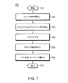
図7は、例えば実装された配備モジュール160等により本発明の実施形態においてユニットプロセスモデルを配備する、コンピュータに実装される方法700を示すフロー図である。方法700は、ステップ710にて開始する。方法700はステップ720にて、校正された前記ユニットプロセスモデルを記憶した前記構成ファイル(コンフィグレーションファイル)を読み出し、当該構成ファイルをリアルタイムプラントデータと関連付けて、前記モデルをオンラインで動的に実行する。一部の実施形態では、前記構成ファイルは、構築方法500及び校正方法600により生成された、保存及び構成されたファイルとして取り出されたものである。方法700(ステップ720)は、まず、前記ユニットプロセスモデルにおける変数を、(図5のステップ560〜ステップ570で提供された)当該変数それぞれのマッピングされた計器タグに結び付ける。方法700は、次に、ステップ730にて、前記リアルタイムプラントヒストリアンから、測定されたプラントデータを取り出し、取り出された当該データを適応させる(すなわち、内挿及び平均化する)。前記リアルタイムプラントヒストリアンは、集中プラントデータストア130に位置してもよい。当該測定されたプラントデータは、方法500のステップ560〜ステップ570からのマッピングされた前記計器タグに対応する。
[How to deploy a unit process model]
FIG. 7 is a flow diagram illustrating a computer-implemented
方法700は、次に、ステップ740にて、前記オンラインのユニットプロセスモデルの動的に実行可能なバージョンを生成する。これを行うために、方法700(ステップ740)は、マッピングされた各計器タグについての変数ブロック(測定ブロック)を生成し、当該変数ブロックを用いて、マッピングされた当該計器についての前記測定されたプラントデータを当該マッピングされた計器についての前記モデルによる算出値にリンクさせる。各測定ブロックは、前記リアルタイムプラントデータの測定値を保持するための変数と、モデル算出結果を保持するための変数と、当該測定プラント値と当該モデル算出値との間の差分つまりオフセットを表す変数という3種類の変数を提供する。前記測定ブロックのサブセットについてのオフセットは、前記モデルがプラントでの実際の(物理的な)操業を厳密に反映することを確実にするための調整因子として用いられる。方法700(ステップ740)は、さらに、前記ユニットからの各材料ストリームについて、前記モデル化された動作ユニットのストリーム変数のブックキーピング(記録付け)を体系化した分析ブロックを生成する。方法700は、また、前記ユニットプロセスモデルの範囲を当該モデルの一体化した部分を超えて拡張するための少なくとも1つの計算ブロックを生成してもよい。
The
当該計算ブロックは、以下の例示的な機能のために方法700(ステップ740)により用いられる。まず、方法700は、前記計算ブロックを、プロセス変数の代数的組合せ(例えば、合計ストリーム流量を物理的なプラントにおいて存在するストリーム流量の合計として算出すること、塔での圧力降下を塔頂及び塔底のトレイ値から算出すること等)として用いる。方法700は、また、前記計算ブロックを、プロセス変数の単位変換(例えば、濃度変数をモルから質量に変換すること等)のために用いる。方法700は、さらに、前記計算ブロックを、モデル変数をプラント測定値と整合するように設定する(例えば、モデル原料流量をプラントで観測された数値に一致するように設定すること等)ために用いる。
The calculation block is used by method 700 (step 740) for the following exemplary functions. First, the
前記オンラインのユニットプロセスモデルの前記動的に実行可能なバージョンを生成するために、方法700はステップ740にて、次に、当該モデルが整然(square)となる(すなわち、式の数が未知の変数の数に等しくなる)ように当該モデルの変数についての正確な仕様を設定する。そして、方法700(ステップ740)は、前記リアルタイムプラントヒストリアンから前記プラントデータのリアルタイム値を取り出して、前記モデルの固定変数(すなわち、MV)を正確に設定する。方法700(ステップ740)は、さらに、方法600の実行により決定された、前記モデルの前記校正パラメータの数値(すなわち、図6Aの流量ステップ630及び温度ステップ635からの校正されたパラメータ)を設定する。方法700(ステップ740)は、さらに、ソルバ(解算出手段)のパラメータを、高速解を導く数値(例えば、デフォルト値等)に設定する。そして、方法700(ステップ740)は、前記ユニットが定常−定常状態であるか否かを判定し、(ステップ640の供給材料推定手段を用いて)供給材料の組成を推定して、前記オンラインのユニットプロセスモデルの前記動的に実行可能なバージョンを完成させる。方法700は、前記モデル化されたユニットの最新(現在)の物質収支誤差が(方法600に関して説明したように)物質収支平均と偏差とにより決まる校正時に観測された定常状態バンド内に収まる場合には、当該モデル化されたユニットを定常状態であると見なす。
To generate the dynamically executable version of the on-line unit process model, the
方法700はステップ750にて、ステップ730からの前記取り出され且つ適応させられたデータを用いて、前記オンラインのユニットプロセスモデルの前記動的に実行可能なバージョンの解を求めて、前記動作ユニットについての対象のKPIの数値を算出する。当該対象のKPIの算出値は、1つのプロセス変数の測定値(例えば、生成物の不純物、凝縮器およびリボイラの負荷等)、予め定められた式を用いて少なくとも1つのプロセス変数の測定値から算出された指数(例えば、算出されたフラッディング率が最も高い塔トレイに対応するトレイ指数等)などを含んでもよい。KPI値の算出の例については、米国特許出願第15/141,701号等を参照のこと(この全体は、参照をもって本明細書に取り入れたものとする)。
The
方法700はステップ760にて、算出された前記KPI値をリアルタイムプラントヒストリアンに書き込む。前記リアルタイムプラントヒストリアンは、集中データストア130又はプラントネットワーク120上の別の場所に位置してもよい。プラントシステム(例えば、図1の計測制御操業コンピュータ175等)やプラント従事者(例えば、プラントオペレータ等)は、そのリアルタイムプラントヒストリアンからの前記KPI値にアクセスして当該KPI値を用いて、前記モデル化された動作ユニットの動作についてのリアルタイムパフォーマンス監視及び予測分析(例えば、インターフェース110を介してユーザに、蒸留塔についての発端のフラッディング事象を知らせる等)を実行してもよい。前記ユニットプロセスモデルによりモデル化された前記動作ユニットが蒸留塔である場合には前記方法は、さらに、(例えば、ステップ650で調整された流体力学的モデルを用いて)塔の流体力学を予測し、前記ユニットプロセスモデルの実行のための安定性図を生成する。方法700は、ステップ770にて終了する。
The
[ルールエンジンの生成]
ルールエンジンが、本発明の実施形態において予測知見及び指示案内のために生成されてもよい。ルールエンジンは、ドメイン固有論理に関連して、少なくとも1つのモデルの組合せを参照する。例えば、前記ルールエンジンは、(例えば、図8Bに示すようなユーザインターフェースを介した)ユーザ入力と、(一部の実施形態では、方法500により生成されたモデルによって算出される)第一原理モデル予測と、プラントタグデータとの組合せを、入力として受け取ってもよい。前記ルールエンジンは、多数の事象を予測するのに用いられてもよい。当該多数の事象は、:(i)物理的な計器により得られたプラント測定値と第一原理モデル予測との不一致;および(ii)差し迫った不所望の動作事象;を含む。前記ルールエンジンは、予測された事象に基づいて、当該事象の警告や改善措置の提案を発行することができる。前者の例示的な事象種類(すなわち、プラント測定値と第一原理モデル予測との不一致)は、前記第一原理モデルが最新(現在)の設備操業に関してもはや適切に校正されていないことや、前記物理的な計器においてドリフトが発生している可能性があり当該物理的な計器の再校正が必要であることをユーザに知らせるのに用いられることができる。
Generate Rule Engine
A rules engine may be generated for predictive knowledge and guidance in embodiments of the present invention. The rules engine refers to the combination of at least one model in connection with domain specific logic. For example, the rules engine may generate user input (eg, via a user interface as shown in FIG. 8B) and a first principles model (computed by the model generated by the
蒸留塔の場合、後者の例示的な事象種類(すなわち、差し迫った不所望の動作事象)の特定の一実施形態は、塔フラッディングである。フラッディングは、「[蒸留]塔内の液体の過剰な蓄積」として定義される(例えば、Kister達による"Distillation Operation (Mechanical-Engineering), Book-mart Press, Inc., pg. 376 (1990)等を参照のこと(この全体は、参照をもって本明細書に取り入れたものとする))。フラッディングの症状は、分離損失を含む不所望な動作状態を含み得る。分離損失は、不純物の上昇や塔トレイ温度差の低下により検出されることができる。フラッディングの症状は、さらに、塔又は塔の一部での過剰な圧力降下および塔差圧の急激な上昇を含み得る。塔フラッディングによる塔分離損失は、仕様に合わない物質の製造につながり得るので、フラッディングの開始を予測してフラッディングシナリオを回避するための指示案内を提供する必要性を駆り立てる。前記ルールエンジンは、これらの症状に基づいて塔フラッディング系の事象をユーザに知らせること促進する。 In the case of a distillation column, one particular embodiment of the latter exemplary event type (i.e. impending undesirable operating event) is column flooding. Flooding is defined as "excess accumulation of liquid in the [[distillation] column]" (for example, "Distillation Operation (Mechanical-Engineering)" by Kister et al., Book-mart Press, Inc., pg. 376 (1990), etc. (This is incorporated herein by reference in its entirety)) Symptoms of flooding may include undesirable operating conditions including separation loss, which may include rise in impurities and / or towers. The symptoms of the flooding can further include an excessive pressure drop in the column or part of the column and a sharp rise in the differential pressure of the column. Since this can lead to the production of substances that do not meet the specifications, it drives the need to provide guidance on predicting the onset of flooding and avoiding flooding scenarios. Down promotes that inform the event towers flooding system to the user based on these symptoms.
図8Aは、本発明の実施形態において指示案内のためのルールエンジンを生成する、コンピュータに実装される方法を示すフロー図である。方法800はステップ805にて、前記ルールエンジンを構築する。当該ルールエンジンは、当該ルールエンジンにより消費される少なくとも1つの警告スコアを生成する、少なくとも1つのブラックボックス(第一原理でない)モデル(警告モデルとも称される)で構成されている。方法800(ステップ805)は、ユーザ入力、(一部の実施形態では、方法500で生成されたモデルによって算出される)第一原理モデル予測及びプラントタグデータを含み得るモデル入力を受け取って前記少なくとも1つの警告スコアを生成するように、前記警告モデルを構築する。一部の実施形態では、前記警告モデルが前記少なくとも1つの警告スコア(Score)を、下記の関数形式(式中、各モデル入力iは、それ自身の係数(Coeff)、定数(Constant)及び指数(Exponent)のルールエンジンパラメータを有する)を用いることによって算出する:
FIG. 8A is a flow diagram illustrating a computer-implemented method of generating a rules engine for directing guidance in an embodiment of the present invention. The
If mini<= (Xi-Constanti) <= maxi:
Score = Sum(Coeffi*(Xi-Constanti)^Exponenti)
Else:
Score = 0
If min i <= (X i -Constant i ) <= max i :
Score = Sum (Coeff i * (X i -Constant i ) ^ Exponent i )
Else:
Score = 0
前記ルールエンジンは、構築されると、生成された前記少なくとも1つの警告スコアのそれぞれを調べて、それぞれの当該警告スコアが警告閾値を超えるか否かを判定する。警告スコアが警告閾値を超えた場合には、前記ルールエンジンが一連のイベントを実行してもよい。一連のイベントは、図8Bのユーザインターフェースを介してユーザに警告のメッセージを画面表示することや、ユーザに提示される指示案内の算出を含む。 The rule engine, when constructed, examines each of the generated at least one alert score to determine whether each respective alert score exceeds an alert threshold. The rules engine may execute a series of events if the warning score exceeds a warning threshold. The series of events include displaying a warning message on the screen of the user via the user interface of FIG. 8B and calculating the instruction guidance presented to the user.
方法800はステップ810にて、前記ルールエンジンの前記警告(ブラックボックス)モデルのうちの一つとして、容量警告モデルを構築する。前記ルールエンジンのための警告スコアを生成する前記警告モデルは、多数のプロセスユニット180に対して用いられる汎用的なもの(例えば、計測誤差についての警告スコアを生成するモデル等)であってもよく、あるいは、特定のユニット180動作タイプに対して特化して用いられるものであってもよい。特定のユニット動作に特化した警告モデルは、ドメイン知識から構築されてもよい。蒸留塔に特化した例示的な警告は、発端のフラッディング事象についてユーザに警告するのに用いられることができる容量警告である。方法800(ステップ810)は、(容量警告スコアを生成する)容量警告モデルを、様々なモデル入力に基づいて構築する。第一に、方法800(ステップ805)は、前記容量警告モデルを、前記蒸留塔の少なくとも1つの指定されたトレイでの塔フラッディング因子(ファクタ)の第一原理モデルによる予測に基づいて構築してもよい。高い予測値は、前述の「流体力学的モデルの調整」の欄で詳述したように、塔フラッディングの確率が高いことを指す。方法800(ステップ805及びステップ810)は、前記第一原理モデルの当該予測を、図5の方法500により構築された前記校正されたモデルを用いることによって取得してもよい。
The
第二に、方法800(ステップ810)は、前記容量警告モデルを、プラントで経時的に測定された少なくとも1つの塔部位差圧の急激な上昇挙動の類似点の定量化に基づいて構築してもよい。第三に、方法800(ステップ810)は、前記容量警告モデルを、プラントで経時的に測定された少なくとも1つの塔部位温度差(DT)の低下挙動の類似点の定量化に基づいて構築してもよい。方法800(ステップ810)は、これらの定量化(急激な上昇及び低下挙動)を各種手法により取得してもよい。前記各種手法は、時系列データの線形回帰を実行して時間の関数としてのデータの、最も良好にフィッティングする傾きを得るというトレンディングを用いることを含む。また、方法800(ステップ810)は、これらの定量化(急激な上昇及び低下挙動)を、時系列データのうちの一部が予め指定されたパターンにどれほど密接に合致するのかを定量化するための動的時間伸縮アルゴリズムを適用することによるパターン認識(例えば、RakthanmanonによるSearching and Mining Trillions of Time Series Subsequences under Dynamic Time Warping(「動的時間伸縮による何兆もの部分時系列の検索及びマイニング」), 18thACM SIGKDD Converence on Knowledge discovery and Data Mining, August 12-16, 2010等を参照のこと(この全体は、参照をもって本明細書に取り入れたものとする))を用いて取得してもよい。第四に、方法800(ステップ810)は、前記容量警告モデルを、プラントで測定された少なくとも1つの塔部位差圧(DP)の最新(現在)値に基づいて構築してもよい。 Second, the method 800 (step 810) builds the volume warning model based on quantifying the similarities of the rapid rising behavior of at least one tower-site differential pressure measured at the plant over time. It is also good. Third, the method 800 (step 810) builds the volume warning model based on quantifying the similarity of the decreasing behavior of at least one tower site temperature difference (DT) measured over time at the plant. May be The method 800 (step 810) may obtain these quantifications (rapid rise and fall behavior) by various techniques. The various approaches include using trending to perform linear regression of time series data to obtain the best fitting slope of the data as a function of time. Also, the method 800 (step 810) is to quantify how closely these quantifications (rapid ups and downs) correspond to a pre-specified pattern of some of the time series data. Recognition by applying a dynamic time warping algorithm (for example, Search and Mining Trillions of Time Series Subsequences under Dynamic Time Warping by Rakthanmanon ("Searching and Mining Trillion Partial Time Series by Dynamic Time Warping"), 18 th ACM SIGKDD Converence on Knowledge discovery and Data Mining, August 12-16, see the like 2010 (all this, with reference to those incorporated herein)) may be obtained using. Fourth, the method 800 (step 810) may construct the volume alert model based on the latest (current) value of at least one tower-site differential pressure (DP) measured at the plant.
方法800は(ステップ815)にて、前記ルールエンジンのパラメータを調整する。前記ルールエンジンがユニット動作に関連する不所望の事象を予測できるためには、当該ルールエンジンのモデル(例えば、警告モデル等)についてのパラメータを適切に決定することが要求される。方法800はステップ815にて、ヒューリスティクスのアプローチを用いて、前記ルールエンジンのモデルパラメータを調整する。蒸留塔についての容量警告モデルの場合、方法800(ステップ815)によって、ユーザは、動作コンテキスト(正常またはフラッディング)を提供することができる。そして、方法800(ステップ815)は、発端のフラッディング時にフラッディング事象が発生しているかもしれないことをユーザに警告する確率が最良となる、ルールエンジンのモデルパラメータ(警告パラメータ)を算出する。方法800(ステップ815)は、当該警告パラメータを、目的関数と当該目的関数を最小化することが可能なソルバ(解算出手段)との2つのコンポーネントを用いて調整する。この目的関数は、(人間のユーザ又はコンピュータに実装されたシステムにより)次のような複数の目的によって定義される。第一に、前記目的関数は、前記モデルの警告スコアが正常動作時に前記警告閾値を超えることがないように(すなわち、フォールスポジティブを防ぐように)定義される。第二に、前記目的関数は、前記モデルの警告スコアが異常動作窓時に前記警告閾値を超えることを確実にするように定義される。第三に、前記目的関数は、正常時間窓と異常時間窓とで前記モデルのスコアの平均値間に隔たりが生じるように定義される。
The
方法800はステップ820にて、ステップ805〜ステップ815で構築及び調整された前記ルールエンジンの実行から、指示案内を決定する。警告スコア閾値に合格していないと前記ルールエンジンが判断すると当該ルールエンジンは、(提供されたドメイン知識に基づく)論理を実行して、対処可能な事項の形態で指示案内をユーザに提示する。蒸留塔についての容量警告モデルの例では、警告のトリガによって、前記ルールエンジンが、少なくとも次の対処可能な事項を検討する:(1)塔還流流量の低減;および(2)少なくとも1つの原料ストリームの原料流量の低減。
The
前記ルールエンジンは、前記警告スコア閾値に合格していない場合の前記指示案内を決定するための条件を適用する。前記容量警告モデルの例では、前記ルールエンジンが、(例えば、図8Bのユーザインターフェース画面を介して)ユーザにより提供された、最新(現在)の生成物ストリーム不純物レベルについての不純物仕様限度を、第一原理モデルによる塔還流及び少なくとも1つの原料ストリームの流量に関する塔生成物不純物の感度についての予測と共に適用する。例えば、前記ルールエンジンは、前記最新(現在)の生成物ストリーム不純物レベルがユーザ指定の前記限度に違反したか否かを判定する。前記ルールエンジンは、さらに、(一部の実施形態では、方法600により生成された)前記第一原理モデルが還流流量の差分動き(動きの大きさは、図8Bのユーザインターフェースにおける設定可能パラメータであってもよい)に基づいて不純物仕様違反を予測しているか否かを判定する。前記ルールエンジンが違反を判定した場合には、当該ルールエンジンが(例えば、図8Bのユーザインターフェース画面を介して)指示案内を提供し、蒸留塔の前記還流流量を低減させるのではなく少なくとも1つの前記原料流量を低減することをユーザに提案する。
The rule engine applies conditions for determining the guidance when the warning score threshold is not passed. In the example of the capacity alert model, the rules engine may generate an impurity specification limit for the current (current) product stream impurity level provided by the user (eg, via the user interface screen of FIG. 8B). It is applied together with the prediction of the sensitivity of column product impurities with respect to column reflux and flow of at least one feed stream according to one principle model. For example, the rules engine determines whether the current (current) product stream impurity level violates the user specified limit. The rule engine further includes: the first principle model (generated by the
[デジタル処理環境]
図9に、本発明が実装され得るコンピュータネットワーク又は同様のデジタル処理環境を示す。
[Digital processing environment]
FIG. 9 illustrates a computer network or similar digital processing environment in which the present invention may be implemented.
少なくとも1つのクライアントコンピュータ/装置50および少なくとも1つのサーバコンピュータ60は、アプリケーションプログラムなどを実行する処理装置、記憶装置および入出力装置を提供する。少なくとも1つのクライアントコンピュータ/装置50は、さらに、他のコンピューティングデバイス(他のクライアント装置/プロセス50および1つ以上の他のサーバコンピュータ60を含む)へと通信ネットワーク70を介して接続(リンク)されることが可能である。通信ネットワーク70は、リモートアクセスネットワーク、グローバルネットワーク(例えば、インターネット等)、クラウドコンピューティングサーバ又はサービス、世界中のコンピュータの集まり、ローカルアエリア又はワイドエリアネットワーク、および現在それぞれのプロトコル(TCP/IP, Bluetooth(登録商標)など)を用いて互いに通信するゲートウェイの一部であってもよい。それ以外の電子デバイス/コンピュータネットワークアーキテクチャも好適である。
At least one client computer /
図10は、図9のコンピュータシステムにおけるコンピュータ(例えば、クライアントプロセッサ/装置50、サーバコンピュータ60等)の内部構造を示す図である。それぞれのコンピュータ50,60は、コンピュータ又は処理システムの構成要素間でのデータ伝送に利用される一連のハードウェアラインであるシステムバス79を備える。バス79は、本質的に、コンピュータシステムの相異なる構成要素(例えば、プロセッサ、ディスクストレージ、メモリ、入出力ポート、ネットワークポート等)を接続して当該構成要素間での情報の伝送を可能にする共有の導管である。システムバス79には、様々な入出力装置(例えば、キーボード、マウス、ディスプレイ、プリンタ、スピーカ等)をコンピュータ50,60に接続するための入出力装置インターフェース82が取り付けられている。ネットワークインターフェース86は、コンピュータが、ネットワーク(例えば、図9のネットワーク70等)に取り付けられた様々な他の装置へと接続することを可能にする。メモリ90は、本発明の一実施形態(例えば、図1〜図8Bに関して先述したユーザインターフェース及び動作手順コード100,200,300,400,500,600,700,800等)を実現するように用いられるコンピュータソフトウェア命令92およびデータ94を記憶する揮発性の記憶部である。ディスクストレージ95は、本発明の一実施形態を実現するように用いられるコンピュータソフトウェア命令92およびデータ94を記憶する不揮発性の記憶部である。データ94は、前述した前記オフラインのモデル、前記プロセスモデルのフローシート、前記データヒストリアンのエントリ/タグ/マッピング、前記第一原理モデル、関連付けられた調和データセット、流体力学的モデル、ルールエンジンなどを含んでもよい。システムバス79には、さらに、コンピュータ命令を実行する中央演算処理装置84が取り付けられている。
FIG. 10 is a diagram showing an internal structure of a computer (eg, client processor /
一実施形態において、プロセッサルーチン92及びデータ94は、コンピュータプログラムプロダクト(概して符号92で表す)である。当該コンピュータプログラムプロダクトは、本発明にかかるシステム用のソフトウェア命令の少なくとも一部を提供するコンピュータ読取り可能媒体(例えば、少なくとも1つのDVD−ROM、CD−ROM、ディスケット、テープなどの取外し可能な記憶媒体等)を含む。コンピュータプログラムプロダクト92は、当該技術分野において周知である任意の適切なソフトウェアインストール方法によってインストールされることができる。また、他の実施形態では、前記ソフトウェア命令の少なくとも一部が、ケーブルおよび/または通信および/または無線接続を介してダウンロードされるものであってもよい。他の実施形態において、本発明にかかるプログラムは、伝播媒体における伝播信号(例えば、電波、赤外線波、レーザ波、音波、インターネットなどのグローバルネットワーク又は他の少なくとも1つのネットワークによって伝播される電気波等)に組み込まれた、コンピュータプログラム伝播信号プロダクト107である。このような搬送媒体又は信号が、本発明にかかるルーチン/プログラム92用のソフトウェア命令の少なくとも一部を提供する。
In one embodiment,
代替的な実施形態では、前記伝播信号が、伝播媒体で搬送されるアナログ搬送波又はデジタル信号である。例えば、前記伝播信号は、グローバルネットワーク(例えば、インターネット等)、電気通信網又は他のネットワークによって伝播されるデジタル信号であってもよい。一実施形態では、前記伝播信号が、ある期間に前記伝播媒体によって送信される信号であり、例えば、数ミリ秒、数秒、数分又はそれ以上の期間にネットワークによってパケットで送信される、ソフトウェアアプリケーション用の命令等である。他の実施形態において、コンピュータプログラムプロダクト92の前記コンピュータ読取り可能媒体は、コンピュータシステム50が受け取って読取りできる伝播媒体である。例えば、コンピュータシステム50は、前述したコンピュータプログラム伝播信号プロダクトの場合のように、伝播媒体を受け取ってその伝播媒体に組み込まれた伝播信号を特定する。
In an alternative embodiment, the propagating signal is an analog carrier or digital signal carried by a propagating medium. For example, the propagated signal may be a digital signal propagated by a global network (eg, the Internet, etc.), a telecommunications network, or another network. In one embodiment, a software application in which the propagated signal is a signal transmitted by the propagation medium in a period of time, for example, transmitted in packets by a network in a few milliseconds, a few seconds, a few minutes or more. And the like. In another embodiment, the computer readable medium of
一般的に言って、「搬送媒体」つまり過渡キャリアという用語は、前述した過渡的信号、伝播信号、伝播媒体、記憶媒体などを包含する。 Generally speaking, the term "carrier medium" or transient carrier includes the aforementioned transient signals, propagation signals, propagation media, storage media and the like.
他の実施形態では、プログラムプロダクト92が、いわゆるサービスとしてのソフトウェア(Saas:「サース」)、またはエンドユーザをサポートする他のインストールもしくは通信として実装されてもよい。
In other embodiments, the
本明細書で引用した全ての特許、特許出願公開公報および刊行物の全教示内容は、参照をもって本明細書に取り入れたものとする。 The entire teachings of all patents, patent application publications and publications cited herein are hereby incorporated by reference.
本発明を例示的な実施形態を参照しながら具体的に図示・説明したが、当業者であれば、添付の特許請求の範囲に包含された本発明の範囲を逸脱しない範疇で形態や細部に様々な変更を施せることを理解するであろう。 While the present invention has been particularly illustrated and described with reference to the exemplary embodiments, those skilled in the art will recognize that the invention can be embodied in forms and details without departing from the scope of the invention as encompassed by the appended claims. It will be understood that various changes can be made.
Claims (22)
産業プラントのプラントワイドプロセスモデルであって、前記産業プラントのオフライン操業を実行するように構成されているプラントワイドプロセスモデルを特定する過程と、
特定された前記プラントワイドプロセスモデルに含まれる、モデル化された動作ユニットであって、前記産業プラントにおける実際の動作ユニットに対応するモデル化された動作ユニットを選択する選択過程と、
特定された前記プラントワイドプロセスモデルを、選択された前記モデル化された動作ユニットのユニットプロセスモデルに変換する変換過程と、
前記ユニットプロセスモデルを、前記実際の動作ユニットの計器によって収集されたリアルタイム測定値に基づいて機能できるように再校正する再校正過程と、
再校正された前記ユニットプロセスモデルであって、前記実際の動作ユニットの前記計器によって収集されたリアルタイム測定値に基づいて、前記産業プラントにおける前記実際の動作ユニットの動作挙動を予測するKPIを算出するユニットプロセスモデルを前記産業プラントにおいてオンラインで配備する配備過程と、
前記実際の動作ユニットを、当該実際の動作ユニットの予測された前記動作挙動に従って制御する制御過程と、
を備える、方法。 A method implemented on a computer to generate an on-line unit process model, comprising:
Identifying a plant wide process model of an industrial plant, wherein the plant wide process model is configured to perform offline operation of said industrial plant;
A selected operation unit included in the identified plant-wide process model, wherein the selected operation unit corresponds to an actual operation unit in the industrial plant;
A conversion process for converting the identified plant-wide process model into a unit process model of the selected modeled operation unit;
Recalibrating the unit process model so that it can function based on real-time measurements collected by the meter of the actual operating unit;
Calculate a KPI, which is the recalibrated unit process model, and which predicts the operation behavior of the actual operating unit in the industrial plant based on real-time measurement values collected by the meter of the actual operating unit A deployment process for deploying unit process models online at the industrial plant;
Controlling the actual operating unit according to the predicted operating behavior of the actual operating unit;
A method comprising.
選択された前記モデル化された動作ユニットとは無関係な変数及び式を除去する除去副過程、
選択された前記モデル化された動作ユニットの仕様を標準仕様に置換する置換副過程、
計算基準を標準形式に変換する変換副過程、
選択された前記モデル化された動作ユニットのプロセス変数
を再設定する再設定副過程、ならびに
選択された前記モデル化された動作ユニットの制御ループであって、選択された前記モデル化された動作ユニットの動作目的を特定する制御ループを決定する決定副過程、
を含む、方法。 The method according to claim 1, wherein the converting step of converting the specified plant wide process model is:
An elimination subprocess that removes variables and expressions that are not related to the selected modeled motion unit,
A substitution subprocess for replacing the selected specification of the modeled operation unit with a standard specification,
Conversion subprocess, which converts the calculation basis to standard form,
A resetting sub-process for resetting process variables of the selected modeled operating unit, and a control loop of the selected modeled operating unit, the selected modeled operating unit Decision subprocess that determines the control loop that identifies the
Method, including.
選択された前記モデル化された動作ユニットの操作変数及び出力変数を特定すること、ならびに
特定された前記操作変数及び前記出力変数のそれぞれを、少なくとも1つの計器タグにマッピングすること、
を有する、方法。 5. The method of claim 4, wherein the resetting substep of resetting the process variable is:
Identifying the selected manipulated variables and output variables of the modeled motion unit, and mapping each of the identified manipulated variables and the output variables to at least one instrument tag;
Have a way.
リアルタイムプラントヒストリアンから取り出されたプラントデータに基づくデータセットであって、校正された時間ホライズン中に定常状態で収集された、前記プラントデータのサブセットを含むデータセットを生成する生成副過程、
前記ユニットプロセスモデルにおけるモデル化された流量を調和させる副過程であって、前記ユニットプロセスモデルが前記産業プラントにおいて実際の流量計器によって収集された測定値を用いて機能することを可能にする、流量調和副過程、
前記ユニットプロセスモデルにおけるモデル化された温度を調和させる副過程であって、前記ユニットプロセスモデルが前記産業プラントにおいて実際の流量計器によって収集された測定値を用いて機能することを可能にする、温度調和副過程、
選択された前記モデル化された動作ユニットに入る原料ストリームの組成を前記ユニットプロセスモデルが推定することを可能にする原料推定手段を構築する構築副過程、ならびに
選択された前記モデル化された動作ユニットが蒸留塔である場合、前記ユニットプロセスモデルにおける当該蒸留塔の内部の液体・蒸気往来流を表す流体力学的モデルを調整する調整副過程、
を含む、方法。 The method according to claim 1, wherein the recalibration step of recalibrating the unit process model is:
A generation subprocess that generates a data set based on plant data extracted from a real time plant historian, the data set including a subset of the plant data collected in steady state during a calibrated time horizon,
A sub-process reconciling modeled flow rates in the unit process model that allows the unit process model to function with measurements collected by actual flow meters in the industrial plant Harmony subprocess,
A sub-process that reconciles modeled temperatures in the unit process model, allowing the unit process model to function in the industrial plant with measurements collected by actual flow meters. Harmony subprocess,
A building sub-process that builds up the raw material estimation means that enables the unit process model to estimate the composition of the raw material stream entering the selected modeled operating unit, and the selected modeled operating unit An adjustment subprocess for adjusting a hydrodynamic model representing liquid / vapor flow inside the distillation column in the unit process model,
Method, including.
前記実際の計器それぞれにおける期待誤差を選択すること、
前記データセットの前記プラントデータを、トレーニングセットとテストセットに分けること、
最適化モデルを前記トレーニングセットにおける各データ点について生成することであって、当該最適化モデルの解を求めることにより、前記モデル化された流量又は前記モデル化された温度についての校正パラメータを決定すること、および
シミュレーションモデルを前記テストセットにおける各データ点について生成することであって、当該シミュレーションモデルの解を求めることにより、決定された前記校正パラメータの品質を決定すること、
を有する、方法。 7. The method according to claim 6, wherein said flow conditioning sub-process of reconciling modeled flow rates or said temperature conditioning sub-process of reconciling modeled temperatures further comprises:
Selecting an expected error in each of the actual instruments,
Separating the plant data of the data set into a training set and a test set;
Generating an optimization model for each data point in the training set and determining a calibration parameter for the modeled flow rate or the modeled temperature by solving the optimization model. And generating a simulation model for each data point in the test set, and determining the quality of the determined calibration parameter by solving the simulation model.
Have a way.
前記実際の温度計器によって測定された温度と前記ユニットプロセスモデルによって算出された温度との分離度を表す効率パラメータ、および
前記実際の動作ユニットにおいて測定された圧力降下が前記ユニットプロセスモデルによって算出された圧力降下と合致するか否かを表す通気パラメータを含む、方法。 The method according to claim 7, wherein the calibration parameter for the modeled temperature is
An efficiency parameter that represents the degree of separation between the temperature measured by the actual temperature meter and the temperature calculated by the unit process model, and the pressure drop measured in the actual operation unit is calculated by the unit process model A method that includes an aeration parameter that indicates whether it matches the pressure drop.
前記ユニットプロセスモデルの動的に実行可能なバージョンを生成する副過程であって、前記実際の動作ユニットの前記計器によるリアルタイム測定値を前記ユニットプロセスモデルによって算出される対応する数値にリンクする変数を生成する、副過程、
前記実際の動作ユニットのリアルタイム測定値を取り出す副過程であって、前記モデルに、リンクされた変数をリアルタイム測定値と関連付けて設定する、副過程、
前記ユニットプロセスモデルの前記動的に実行可能なバージョンの解を求める副過程であって、リンクされた変数を算出されるモデル値に関連付けて設定し、前記モデル化された動作ユニットのKPIについての数値を決定する、副過程、ならびに
決定された前記KPIを、当該KPIに基づいて前記実際の動作ユニットを予測及び制御するように構成されたプラントコンピュータによるアクセスのために、リアルタイムヒストリアンに書き込む副過程、
を含む、方法。 The method according to claim 1, wherein the deploying step of deploying the recalibrated unit process model on-line in the industrial plant;
A subprocess that generates a dynamically executable version of the unit process model, which links the real-time measurements by the meter of the actual operating unit to the corresponding numerical values calculated by the unit process model. Subprocess, to generate
A sub-process for extracting real-time measurement values of the actual operation unit, wherein the linked variable is set in the model in association with the real-time measurement values;
A sub-process for finding a solution of the dynamically executable version of the unit process model, wherein linked variables are set in association with calculated model values, and the KPI of the modeled motion unit is determined. The sub-process which determines the value, the sub-process, and the sub-process which writes the determined KPI to a real-time historian for access by a plant computer configured to predict and control the actual operation unit based on the KPI. process,
Method, including.
再校正された前記ユニットプロセスモデルを、前記実際の動作ユニットの事象についての指示案内のユーザへの提供を自動化しているルールエンジンを生成するように適用する過程、
を備える、方法。 The method according to claim 1, further comprising
Applying the recalibrated unit process model to create a rules engine that is automating the provision of guidance to the user about the actual operating unit events;
A method comprising.
プロセッサと、
コンピュータコード命令が記憶されたメモリと、
を備え、前記メモリは、前記プロセッサにより実行されると前記コンピュータコード命令が
a)モデル変換手段であって、
産業プラントのプラントワイドプロセスモデルであって、前記産業プラントのオフライン操業を実行するように構成されたプラントワイドプロセスモデルを取得し、
取得された前記プラントワイドプロセスモデルに含まれる、モデル化された動作ユニットであって、前記産業プラントでの実際の動作ユニットに対応するモデル化された動作ユニットを選択し、
取得された前記プラントワイドプロセスモデルを、選択された前記モデル化された動作ユニットのユニットプロセスモデルに変換するように構成された、モデル変換手段、
b)前記モデル変換手段に応答して、前記ユニットプロセスモデルを再校正するように構成されたモデル校正手段であって、前記再校正により、前記ユニットプロセスモデルが、前記実際の動作ユニットの計器によって収集されたリアルタイム測定値に基づいて機能できるようにする、モデル校正手段、および
c)再校正された前記ユニットプロセスモデルを前記産業プラントにおいてオンラインで配備するように接続された配備エンジンであって、配備された前記ユニットプロセスモデルは、前記実際の動作ユニットの前記計器によって収集されたリアルタイム測定値に基づいて、前記産業プラントでの前記実際の動作ユニットの動作挙動を予測するKPIを算出する、配備エンジン
を当該コンピュータシステムに実装させるように、前記プロセッサに作動的に接続されており、
前記配備エンジンは、前記実際の動作ユニットを、当該実際の動作ユニットの予測された前記動作挙動に従って制御するように構成された制御システム通信する、コンピュータシステム。 A computer system that generates an on-line unit process model,
A processor,
A memory in which computer code instructions are stored;
The computer code instructions when executed by the processor are a) model transformation means,
Obtaining a plant wide process model of an industrial plant, wherein the plant wide process model is configured to perform an offline operation of said industrial plant;
Selecting a modeled operating unit to be included in the acquired plant-wide process model, the one corresponding to the actual operating unit in the industrial plant,
Model conversion means configured to convert the acquired plant-wide process model into a unit process model of the selected modeled operation unit,
b) model calibration means configured to recalibrate the unit process model in response to the model transformation means, wherein the recalibration causes the unit process model to be measured by the meter of the actual operation unit A model calibration means, and c) a deployment engine connected to deploy the recalibrated unit process model on-line in the industrial plant to enable functioning based on collected real-time measurements, The deployed unit process model calculates a KPI that predicts the operating behavior of the actual operating unit in the industrial plant based on real-time measurement values collected by the meter of the actual operating unit. To have the computer system implement the engine It is operatively connected to the processor,
A computer system, wherein the deployment engine communicates with a control system configured to control the actual operating unit according to the predicted operating behavior of the actual operating unit.
選択された前記モデル化された動作ユニットとは無関係な変数及び式を除去し、
選択された前記モデル化された動作ユニットの仕様を標準仕様に置換し、
計算基準を標準形式に変換し、
選択された前記モデル化された動作ユニットのプロセス変数を再設定し、
選択された前記モデル化された動作ユニットの制御ループであって、選択された前記モデル化された動作ユニットの動作目的を特定する制御ループを決定することによって
変換するように構成されている、コンピュータシステム。 The computer system according to claim 12, wherein the model conversion means further includes the plant-wide process,
Remove variables and expressions unrelated to the selected modeled motion unit,
Replace the selected specification of the modeled operation unit with the standard specification,
Convert the calculation basis to a standard form,
Reset the process variables of the selected modeled operating unit;
A control loop of the selected modeled operating unit, configured to transform by determining the control loop identifying the operating purpose of the selected modeled operating unit. system.
選択された前記モデル化された動作ユニットの操作変数及び出力変数を特定し、
特定された前記操作変数及び前記出力変数のそれぞれを、少なくとも1つの計器タグにマッピングすることによって
再設定するように構成されている、コンピュータシステム。 The computer system according to claim 15, wherein the model conversion means further includes the process variable,
Identifying the manipulated variables and output variables of the selected modeled motion unit;
A computer system configured to reconfigure each of the identified manipulated variable and the output variable by mapping to at least one instrument tag.
リアルタイムプラントヒストリアンから取り出されたプラントデータに基づくデータセットであって、校正された時間ホライズン中に定常状態で収集された、前記プラントデータのサブセットを含むデータセットを生成するように構成されたデータセット生成部、
前記ユニットプロセスモデルにおけるモデル化された流量を調和させるように構成された流量調和部であって、当該調和は、前記ユニットプロセスモデルが前記産業プラントにおいて実際の流量計器によって収集された測定値を用いて機能することを可能にする、流量調和部、
前記ユニットプロセスモデルにおけるモデル化された温度を調和させるように構成された温度調和部であって、当該調和は、前記ユニットプロセスモデルが前記産業プラントにおいて実際の流量計器によって収集された測定値を用いて機能することを可能にする、温度調和部、
選択された前記モデル化された動作ユニットに入る原料ストリームの組成を前記ユニットプロセスモデルが推定することを可能にする原料推定手段を構築するように構成された原料推定手段構築部、ならびに
選択された前記モデル化された動作ユニットが蒸留塔である場合、前記ユニットプロセスモデルにおける当該蒸留塔の内部の液体・蒸気往来流を表す流体力学的モデルを調整するように構成された流体力学的モデル調整部、
を含む、コンピュータシステム。 The computer system according to claim 12, wherein the model calibration means is
A data set based on plant data retrieved from a real time plant historian, configured to generate a data set comprising a subset of said plant data collected in steady state during a calibrated time horizon. Set generation unit,
A flow rate harmonization unit configured to harmonize a modeled flow rate in the unit process model, the harmony using measurements the unit process model collects in the industrial plant by an actual flow rate meter Flow-conditioning unit, which allows to function
A temperature conditioning unit configured to reconcile modeled temperatures in the unit process model, the conditioning using measurements that the unit process model was collected by the actual flow meter in the industrial plant Temperature-conditioning unit, which makes it possible to function
A raw material estimation means construction unit configured to construct a raw material estimation means that enables the unit process model to estimate the composition of the raw material stream entering the selected modeled operation unit, and a selected one When the modeled operation unit is a distillation column, a hydrodynamic model adjustment unit configured to adjust a hydrodynamic model representing liquid / vapor flow inside the distillation column in the unit process model ,
Including computer systems.
前記実際の計器それぞれにおける期待誤差を選択し、
前記データセットの前記プラントデータを、トレーニングセットとテストセットに分けて、
最適化モデルを前記トレーニングセットにおける各データ点について生成し、当該最適化モデルの解を求めることにより、前記モデル化された流量又は前記モデル化された温度についての校正パラメータを決定し、
シミュレーションモデルを前記テストセットにおける各データ点について生成し、当該シミュレーションモデルの解を求めることにより、決定された前記校正パラメータの品質を決定するように構成されている、コンピュータシステム。 The computer system according to claim 17, wherein the flow rate adjusting unit and the temperature adjusting unit further include:
Choose the expected error for each of the actual instruments,
Dividing the plant data of the data set into a training set and a test set;
An optimization model is generated for each data point in the training set and a solution of the optimization model is determined to determine calibration parameters for the modeled flow rate or the modeled temperature.
A computer system configured to determine a quality of the determined calibration parameters by generating a simulation model for each data point in the test set and solving for the simulation model.
前記モデル化された流量については、前記実際の流量計器によって測定された流量と前記ユニットプロセスモデルによって算出された流量との差分を表す流量オフセットであり、
前記モデル化された温度については、前記実際の温度計器によって測定された温度と前記ユニットプロセスモデルによって算出された温度との分離度を表す効率パラメータ、および前記実際の動作ユニットにおいて測定された圧力降下が前記ユニットプロセスユニットによって算出された圧力降下と合致するか否かを表す通気パラメータである、コンピュータシステム。 19. The computer system of claim 18, wherein the calibration parameter is:
The modeled flow rate is a flow rate offset representing the difference between the flow rate measured by the actual flow rate meter and the flow rate calculated by the unit process model,
For the modeled temperature, an efficiency parameter representing the degree of separation between the temperature measured by the actual temperature instrument and the temperature calculated by the unit process model, and the pressure drop measured in the actual operating unit A computer system, wherein the ventilation parameter represents whether or not the pressure matches the pressure drop calculated by the unit process unit.
前記実際の動作ユニットの前記計器によるリアルタイム測定値を前記ユニットプロセスモデルによって算出される対応する数値にリンクする変数を生成することを含み、前記ユニットプロセスモデルの動的に実行可能なバージョンを生成し、
前記実際の動作ユニットのリアルタイム測定値を取り出し、前記モデルに、リンクされた変数をリアルタイム測定値と関連付けて設定し、
前記ユニットプロセスモデルの前記動的に実行可能なバージョンの解を求め、リンクされた変数を算出されるモデル値と関連付けて設定し、前記モデル化された動作ユニットのKPIの数値を決定し、
決定された前記KPIを、当該KPIに基づいて前記実際の動作ユニットを予測及び制御するように構成されたプラントコンピュータによるアクセスのために、リアルタイムヒストリアンに書き込むように構成されている、コンピュータシステム。 The computer system of claim 12, wherein the deployment module further comprises:
Generating a dynamically executable version of the unit process model, including generating variables linking real-time measurements by the meter of the actual operating unit to corresponding numerical values calculated by the unit process model; ,
Taking out real-time measurements of the actual operating unit and setting linked variables in the model in association with the real-time measurements;
Solve for the dynamically executable version of the unit process model, set linked variables in association with calculated model values, and determine KPI values of the modeled motion unit;
A computer system configured to write the determined KPIs to a real-time historian for access by a plant computer configured to predict and control the actual operation unit based on the KPIs.
を備える、コンピュータプログラムプロダクトであって、
前記記憶媒体は、オンラインのユニットプロセスモデルを生成するプロセッサにより実行されると前記コード命令が、当該プロセッサに:
産業プラントのプラントワイドプロセスモデルであって、前記産業プラントのオフライン操業を実行するように構成されているプラントワイドプロセスモデルを取得する手順、
取得された前記プラントワイドプロセスモデルに含まれる、モデル化された動作ユニットであって、前記産業プラントにおける実際の動作ユニットに対応するモデル化された動作ユニットを選択する手順、
取得された前記プラントワイドプロセスモデルを、選択された前記モデル化された動作ユニットの第一原理ユニットプロセスモデルに変換する手順、
前記ユニットプロセスモデルを、前記実際の動作ユニットの計器によって収集されたリアルタイム測定値に基づいて機能できるように再校正して、再校正された第一原理ユニットプロセスモデルとする手順、
再校正された前記第一原理ユニットプロセスモデルであって、前記実際の動作ユニットの前記計器によって収集されたリアルタイム測定値に基づいて、前記産業プラントにおける前記実際の動作ユニットの動作挙動を予測するKPIを算出する第一原理ユニットプロセスモデルを前記産業プラントにおいてオンラインで配備する手順、
前記実際の動作ユニットを、当該実際の動作ユニットの予測された前記動作挙動に従って制御する手順
を実行させるように、当該プロセッサに作動的に接続されている、コンピュータプログラムプロダクト。 Non-transitory computer readable storage medium in which code instructions are stored,
A computer program product comprising
When the storage medium is executed by a processor that generates an on-line unit process model, the code instructions cause the processor to:
Procedure for obtaining a plant wide process model of an industrial plant, wherein the plant wide process model is configured to perform offline operation of said industrial plant,
A procedure of selecting a modeled operation unit, which is included in the acquired plant-wide process model, corresponding to an actual operation unit in the industrial plant;
Converting the acquired plant-wide process model into a first principle unit process model of the selected modeled operation unit;
Re-calibrating the unit process model so that it can function based on real-time measurements collected by the meter of the actual operating unit, into a recalibrated first principle unit process model;
KPI, a recalibrated first principle unit process model, which predicts the operating behavior of the actual operating unit in the industrial plant based on real-time measurements collected by the meter of the actual operating unit. Deploying the first principle unit process model for calculating on-line in the industrial plant,
A computer program product operatively connected to the processor to perform a procedure to control the actual operating unit according to the predicted operating behavior of the actual operating unit.
Priority Applications (1)
| Application Number | Priority Date | Filing Date | Title |
|---|---|---|---|
| JP2021064734A JP7394805B2 (en) | 2016-07-07 | 2021-04-06 | Computer system and method for dynamic construction and online deployment of behavior-centered first-principles process models for predictive analysis |
Applications Claiming Priority (3)
| Application Number | Priority Date | Filing Date | Title |
|---|---|---|---|
| US201662359379P | 2016-07-07 | 2016-07-07 | |
| US62/359,379 | 2016-07-07 | ||
| PCT/US2017/040725 WO2018009546A1 (en) | 2016-07-07 | 2017-07-05 | Computer system and method for the dynamic construction and online deployment of an operation-centric first-principles process model for predictive analytics |
Related Child Applications (1)
| Application Number | Title | Priority Date | Filing Date |
|---|---|---|---|
| JP2021064734A Division JP7394805B2 (en) | 2016-07-07 | 2021-04-06 | Computer system and method for dynamic construction and online deployment of behavior-centered first-principles process models for predictive analysis |
Publications (2)
| Publication Number | Publication Date |
|---|---|
| JP2019521444A true JP2019521444A (en) | 2019-07-25 |
| JP2019521444A5 JP2019521444A5 (en) | 2020-07-27 |
Family
ID=59579903
Family Applications (2)
| Application Number | Title | Priority Date | Filing Date |
|---|---|---|---|
| JP2019500348A Pending JP2019521444A (en) | 2016-07-07 | 2017-07-05 | Computer system and method for dynamic construction and on-line deployment of a motion-centric first principles process model for predictive analysis |
| JP2021064734A Active JP7394805B2 (en) | 2016-07-07 | 2021-04-06 | Computer system and method for dynamic construction and online deployment of behavior-centered first-principles process models for predictive analysis |
Family Applications After (1)
| Application Number | Title | Priority Date | Filing Date |
|---|---|---|---|
| JP2021064734A Active JP7394805B2 (en) | 2016-07-07 | 2021-04-06 | Computer system and method for dynamic construction and online deployment of behavior-centered first-principles process models for predictive analysis |
Country Status (4)
| Country | Link |
|---|---|
| US (1) | US10990067B2 (en) |
| EP (1) | EP3482261B1 (en) |
| JP (2) | JP2019521444A (en) |
| WO (1) | WO2018009546A1 (en) |
Cited By (7)
| Publication number | Priority date | Publication date | Assignee | Title |
|---|---|---|---|---|
| US10990067B2 (en) | 2016-07-07 | 2021-04-27 | Aspen Technology, Inc. | Computer system and method for the dynamic construction and online deployment of an operation-centric first-principles process model for predictive analytics |
| JP2021094557A (en) * | 2019-12-13 | 2021-06-24 | 栗田工業株式会社 | Distillation tower management system, distillation tower state analysis method, and distillation tower management method |
| US11630446B2 (en) | 2021-02-16 | 2023-04-18 | Aspentech Corporation | Reluctant first principles models |
| US11754998B2 (en) | 2019-10-18 | 2023-09-12 | Aspentech Corporation | System and methods for automated model development from plant historical data for advanced process control |
| US11782401B2 (en) | 2019-08-02 | 2023-10-10 | Aspentech Corporation | Apparatus and methods to build deep learning controller using non-invasive closed loop exploration |
| US11853032B2 (en) | 2019-05-09 | 2023-12-26 | Aspentech Corporation | Combining machine learning with domain knowledge and first principles for modeling in the process industries |
| US11934159B2 (en) | 2018-10-30 | 2024-03-19 | Aspentech Corporation | Apparatus and methods for non-invasive closed loop step testing with controllable optimization relaxation |
Families Citing this family (17)
| Publication number | Priority date | Publication date | Assignee | Title |
|---|---|---|---|---|
| US11310125B2 (en) | 2018-05-25 | 2022-04-19 | At&T Intellectual Property I, L.P. | AI-enabled adaptive TCA thresholding for SLA assurance |
| EP3605249A1 (en) * | 2018-08-02 | 2020-02-05 | Siemens Aktiengesellschaft | Method for synchronizing, method for operating an industrial installation, system, and computer readable medium and computer program product |
| PL3705963T3 (en) * | 2019-03-08 | 2022-11-07 | Abb Schweiz Ag | Intent-based automation engineering method |
| US20200387818A1 (en) * | 2019-06-07 | 2020-12-10 | Aspen Technology, Inc. | Asset Optimization Using Integrated Modeling, Optimization, and Artificial Intelligence |
| GB201913601D0 (en) * | 2019-09-20 | 2019-11-06 | Microsoft Technology Licensing Llc | Privacy enhanced machine learning |
| US20210125068A1 (en) * | 2019-10-28 | 2021-04-29 | MakinaRocks Co., Ltd. | Method for training neural network |
| EP4066182A1 (en) | 2019-11-26 | 2022-10-05 | Basf Se | Forecasting industrial aging processes with machine learning methods |
| CN111210131B (en) * | 2019-12-30 | 2023-08-18 | 浙江中控技术股份有限公司 | Material statistical balance method for process industry |
| EP3862832A1 (en) * | 2020-02-07 | 2021-08-11 | Basf Se | Generating a representation of a process network comprising at least two interconnected chenical plants |
| US11698609B2 (en) * | 2020-02-20 | 2023-07-11 | Honeywell International Inc. | Cascaded model predictive control with abstracting constraint boundaries |
| US11656606B2 (en) | 2020-08-20 | 2023-05-23 | International Business Machines Corporation | Site-wide operations management optimization for manufacturing and processing control |
| US11774924B2 (en) | 2020-12-03 | 2023-10-03 | Aspentech Corporation | Method and system for process schedule reconciliation using algebraic model optimization |
| WO2022120360A1 (en) * | 2020-12-03 | 2022-06-09 | Aspen Technology, Inc. | Method and system for process schedule reconciliation using machine learning and algebraic model optimization |
| RU2754239C1 (en) * | 2020-12-22 | 2021-08-30 | Владимир Сергеевич Пахомов | Method for structural and parametric synthesis of decision support tools for managing the development of a complex organizational and technical system and a device for its implementation |
| EP4341223A1 (en) | 2021-05-19 | 2024-03-27 | Glass Service, A.S. | Method of control, control system and glass furnace, in particular for temperature/thermal control |
| WO2023012007A1 (en) * | 2021-08-06 | 2023-02-09 | Basf Se | Method for monitoring and/or controlling a chemical plant using hybrid models |
| US20240022492A1 (en) * | 2022-07-12 | 2024-01-18 | Parallel Wireless, Inc. | Top KPI Early Warning System |
Citations (6)
| Publication number | Priority date | Publication date | Assignee | Title |
|---|---|---|---|---|
| US6088630A (en) * | 1997-11-19 | 2000-07-11 | Olin Corporation | Automatic control system for unit operation |
| JP2009509217A (en) * | 2005-08-26 | 2009-03-05 | カトラー,チャールズ,アール. | Adaptive multi-variable MPC controller |
| JP2011054163A (en) * | 2009-08-31 | 2011-03-17 | Fisher-Rosemount Systems Inc | Heat exchange network heat recovery optimization in process plant |
| US9046881B2 (en) * | 2002-10-22 | 2015-06-02 | Fisher-Rosemount Systems, Inc. | Updating and utilizing dynamic process simulation in an operating process environment |
| US20160171414A1 (en) * | 2014-12-11 | 2016-06-16 | Saudi Arabian Oil Company | Method for Creating an Intelligent Energy KPI System |
| US20190179271A1 (en) * | 2016-07-07 | 2019-06-13 | Aspen Technology, Inc. | Computer System And Method For The Dynamic Construction And Online Deployment Of An Operation-Centric First-Principles Process Model For Predictive Analytics |
Family Cites Families (19)
| Publication number | Priority date | Publication date | Assignee | Title |
|---|---|---|---|---|
| EP1042706A1 (en) | 1998-10-06 | 2000-10-11 | Pavilion Technologies, Inc. | Method and system for monitoring and controlling a manufacturing system |
| JP4789277B2 (en) | 2004-04-22 | 2011-10-12 | 横河電機株式会社 | Plant operation support device |
| US8380842B2 (en) | 2007-04-26 | 2013-02-19 | Mtelligence Corporation | System and methods for the universal integration of plant floor assets and a computerized management system |
| CN101925866B (en) * | 2008-01-31 | 2016-06-01 | 费希尔-罗斯蒙特系统公司 | There is the adaptive model predictive controller of the robust of adjustment for compensation model mismatch |
| US9141911B2 (en) * | 2009-05-29 | 2015-09-22 | Aspen Technology, Inc. | Apparatus and method for automated data selection in model identification and adaptation in multivariable process control |
| US8452719B2 (en) * | 2010-06-29 | 2013-05-28 | Rockwell Automation Technologies, Inc. | Extrapolating empirical models for control, prediction, and optimization applications |
| WO2012012723A2 (en) | 2010-07-23 | 2012-01-26 | Saudi Arabian Oil Company | Machines, computer program products, and computer-implemented methods providing an integrated node for data acquisition and control |
| JP6109066B2 (en) | 2011-02-28 | 2017-04-05 | 横河電機株式会社 | Energy management method |
| US9529348B2 (en) * | 2012-01-24 | 2016-12-27 | Emerson Process Management Power & Water Solutions, Inc. | Method and apparatus for deploying industrial plant simulators using cloud computing technologies |
| US9535808B2 (en) | 2013-03-15 | 2017-01-03 | Mtelligence Corporation | System and methods for automated plant asset failure detection |
| WO2015149928A2 (en) | 2014-03-31 | 2015-10-08 | Basf Se | Method and device for online evaluation of a compressor |
| US10031510B2 (en) | 2015-05-01 | 2018-07-24 | Aspen Technology, Inc. | Computer system and method for causality analysis using hybrid first-principles and inferential model |
| US20170308802A1 (en) | 2016-04-21 | 2017-10-26 | Arundo Analytics, Inc. | Systems and methods for failure prediction in industrial environments |
| EP3295611B1 (en) | 2016-07-13 | 2018-12-05 | Incelligent P.C. | Early warning and recommendation system for the proactive management of wireless broadband networks |
| AU2017345796A1 (en) | 2016-10-21 | 2019-05-23 | DataRobot, Inc. | Systems for predictive data analytics, and related methods and apparatus |
| US20180157225A1 (en) | 2016-12-05 | 2018-06-07 | Honeywell International Inc. | Apparatus and method for automatic model identification from historical data for industrial process control and automation systems |
| US10698372B2 (en) | 2017-06-02 | 2020-06-30 | Aspen Technology, Inc. | Computer system and method for building and deploying predictive inferential models online to predict behavior of industrial processes |
| WO2020227383A1 (en) | 2019-05-09 | 2020-11-12 | Aspen Technology, Inc. | Combining machine learning with domain knowledge and first principles for modeling in the process industries |
| US20200387818A1 (en) | 2019-06-07 | 2020-12-10 | Aspen Technology, Inc. | Asset Optimization Using Integrated Modeling, Optimization, and Artificial Intelligence |
-
2017
- 2017-07-05 WO PCT/US2017/040725 patent/WO2018009546A1/en active Search and Examination
- 2017-07-05 US US16/308,190 patent/US10990067B2/en active Active
- 2017-07-05 EP EP17751159.9A patent/EP3482261B1/en active Active
- 2017-07-05 JP JP2019500348A patent/JP2019521444A/en active Pending
-
2021
- 2021-04-06 JP JP2021064734A patent/JP7394805B2/en active Active
Patent Citations (6)
| Publication number | Priority date | Publication date | Assignee | Title |
|---|---|---|---|---|
| US6088630A (en) * | 1997-11-19 | 2000-07-11 | Olin Corporation | Automatic control system for unit operation |
| US9046881B2 (en) * | 2002-10-22 | 2015-06-02 | Fisher-Rosemount Systems, Inc. | Updating and utilizing dynamic process simulation in an operating process environment |
| JP2009509217A (en) * | 2005-08-26 | 2009-03-05 | カトラー,チャールズ,アール. | Adaptive multi-variable MPC controller |
| JP2011054163A (en) * | 2009-08-31 | 2011-03-17 | Fisher-Rosemount Systems Inc | Heat exchange network heat recovery optimization in process plant |
| US20160171414A1 (en) * | 2014-12-11 | 2016-06-16 | Saudi Arabian Oil Company | Method for Creating an Intelligent Energy KPI System |
| US20190179271A1 (en) * | 2016-07-07 | 2019-06-13 | Aspen Technology, Inc. | Computer System And Method For The Dynamic Construction And Online Deployment Of An Operation-Centric First-Principles Process Model For Predictive Analytics |
Cited By (9)
| Publication number | Priority date | Publication date | Assignee | Title |
|---|---|---|---|---|
| US10990067B2 (en) | 2016-07-07 | 2021-04-27 | Aspen Technology, Inc. | Computer system and method for the dynamic construction and online deployment of an operation-centric first-principles process model for predictive analytics |
| US11934159B2 (en) | 2018-10-30 | 2024-03-19 | Aspentech Corporation | Apparatus and methods for non-invasive closed loop step testing with controllable optimization relaxation |
| US11853032B2 (en) | 2019-05-09 | 2023-12-26 | Aspentech Corporation | Combining machine learning with domain knowledge and first principles for modeling in the process industries |
| US11782401B2 (en) | 2019-08-02 | 2023-10-10 | Aspentech Corporation | Apparatus and methods to build deep learning controller using non-invasive closed loop exploration |
| US11754998B2 (en) | 2019-10-18 | 2023-09-12 | Aspentech Corporation | System and methods for automated model development from plant historical data for advanced process control |
| JP2021094557A (en) * | 2019-12-13 | 2021-06-24 | 栗田工業株式会社 | Distillation tower management system, distillation tower state analysis method, and distillation tower management method |
| JP2021094508A (en) * | 2019-12-13 | 2021-06-24 | 栗田工業株式会社 | Distillation tower management system, distillation tower state analysis method, and distillation tower management method |
| JP7056774B2 (en) | 2019-12-13 | 2022-04-19 | 栗田工業株式会社 | Distillation column management system, distillation column state analysis method and distillation column management method |
| US11630446B2 (en) | 2021-02-16 | 2023-04-18 | Aspentech Corporation | Reluctant first principles models |
Also Published As
| Publication number | Publication date |
|---|---|
| EP3482261A1 (en) | 2019-05-15 |
| EP3482261B1 (en) | 2021-05-05 |
| US20190179271A1 (en) | 2019-06-13 |
| JP7394805B2 (en) | 2023-12-08 |
| JP2021101388A (en) | 2021-07-08 |
| WO2018009546A1 (en) | 2018-01-11 |
| US10990067B2 (en) | 2021-04-27 |
Similar Documents
| Publication | Publication Date | Title |
|---|---|---|
| JP7394805B2 (en) | Computer system and method for dynamic construction and online deployment of behavior-centered first-principles process models for predictive analysis | |
| JP7461440B2 (en) | COMPUTER SYSTEM AND METHOD FOR PERFORMING ROOT CAUSE ANALYSIS AND BUILDING PREDICTION MODELS FOR THE OCCURRENCE OF RARE EVENTS IN PLANT-WIDE OPERATIONS - Patent application | |
| JP6928119B2 (en) | Computer systems and methods for building and deploying predictive inference models online | |
| US10921759B2 (en) | Computer system and method for monitoring key performance indicators (KPIs) online using time series pattern model | |
| JP2019521444A5 (en) | ||
| US20190129395A1 (en) | Process performance issues and alarm notification using data analytics | |
| KR20100042293A (en) | System and methods for continuous, online monitoring of a chemical plant or refinery | |
| JP6985833B2 (en) | Data processing equipment, control systems, data processing methods and programs | |
| KR102343752B1 (en) | Computer-implemented method and system for automatically monitoring and determining the status of entire process segments in a process unit | |
| JP2007249997A (en) | Method and system for monitoring industrial process | |
| JP7469991B2 (en) | Diagnosis device and parameter adjustment method | |
| JP6216294B2 (en) | Multiple regression analysis apparatus and multiple regression analysis method | |
| EP3696693A1 (en) | Method and apparatus for monitoring state of device in process industry and medium | |
| AU2024201310A1 (en) | Methods for identifying key performance indicators | |
| JPWO2020188696A1 (en) | Anomaly detection device and abnormality detection method | |
| JP7151312B2 (en) | control system | |
| WO2017046906A1 (en) | Data analysis device and analysis method | |
| JP2019008435A (en) | Trend graph display device | |
| EP4160344A1 (en) | Monitoring apparatus, monitoring method, and monitoring program | |
| EP4020102A1 (en) | System and method for operating an industrial process | |
| JP7416015B2 (en) | Information processing device, alarm prediction method, and alarm prediction program | |
| JP7443609B1 (en) | Learning devices, learning methods and learning programs | |
| WO2023233858A1 (en) | Calculation device and calculation method for neural network | |
| US20220261393A1 (en) | Methods for analysis of time series sensor measurements in physical systems | |
| Kučera et al. | The Digital Twin of a Measuring Process Within the Industry 4.0 Concept |
Legal Events
| Date | Code | Title | Description |
|---|---|---|---|
| A521 | Request for written amendment filed |
Free format text: JAPANESE INTERMEDIATE CODE: A523 Effective date: 20200610 |
|
| A621 | Written request for application examination |
Free format text: JAPANESE INTERMEDIATE CODE: A621 Effective date: 20200610 |
|
| A871 | Explanation of circumstances concerning accelerated examination |
Free format text: JAPANESE INTERMEDIATE CODE: A871 Effective date: 20200610 |
|
| A975 | Report on accelerated examination |
Free format text: JAPANESE INTERMEDIATE CODE: A971005 Effective date: 20200720 |
|
| A131 | Notification of reasons for refusal |
Free format text: JAPANESE INTERMEDIATE CODE: A131 Effective date: 20200818 |
|
| A02 | Decision of refusal |
Free format text: JAPANESE INTERMEDIATE CODE: A02 Effective date: 20201208 |