JP2019518220A - Pipette device, pipette tip coupler, and pipette tip, apparatus and method - Google Patents
Pipette device, pipette tip coupler, and pipette tip, apparatus and method Download PDFInfo
- Publication number
- JP2019518220A JP2019518220A JP2018565881A JP2018565881A JP2019518220A JP 2019518220 A JP2019518220 A JP 2019518220A JP 2018565881 A JP2018565881 A JP 2018565881A JP 2018565881 A JP2018565881 A JP 2018565881A JP 2019518220 A JP2019518220 A JP 2019518220A
- Authority
- JP
- Japan
- Prior art keywords
- pipette tip
- annular
- distal
- section
- wedge
- Prior art date
- Legal status (The legal status is an assumption and is not a legal conclusion. Google has not performed a legal analysis and makes no representation as to the accuracy of the status listed.)
- Pending
Links
Images


Classifications
-
- B—PERFORMING OPERATIONS; TRANSPORTING
- B01—PHYSICAL OR CHEMICAL PROCESSES OR APPARATUS IN GENERAL
- B01L—CHEMICAL OR PHYSICAL LABORATORY APPARATUS FOR GENERAL USE
- B01L3/00—Containers or dishes for laboratory use, e.g. laboratory glassware; Droppers
- B01L3/02—Burettes; Pipettes
- B01L3/0275—Interchangeable or disposable dispensing tips
- B01L3/0279—Interchangeable or disposable dispensing tips co-operating with positive ejection means
-
- B—PERFORMING OPERATIONS; TRANSPORTING
- B01—PHYSICAL OR CHEMICAL PROCESSES OR APPARATUS IN GENERAL
- B01L—CHEMICAL OR PHYSICAL LABORATORY APPARATUS FOR GENERAL USE
- B01L3/00—Containers or dishes for laboratory use, e.g. laboratory glassware; Droppers
-
- B—PERFORMING OPERATIONS; TRANSPORTING
- B01—PHYSICAL OR CHEMICAL PROCESSES OR APPARATUS IN GENERAL
- B01L—CHEMICAL OR PHYSICAL LABORATORY APPARATUS FOR GENERAL USE
- B01L3/00—Containers or dishes for laboratory use, e.g. laboratory glassware; Droppers
- B01L3/02—Burettes; Pipettes
-
- B—PERFORMING OPERATIONS; TRANSPORTING
- B01—PHYSICAL OR CHEMICAL PROCESSES OR APPARATUS IN GENERAL
- B01L—CHEMICAL OR PHYSICAL LABORATORY APPARATUS FOR GENERAL USE
- B01L3/00—Containers or dishes for laboratory use, e.g. laboratory glassware; Droppers
- B01L3/02—Burettes; Pipettes
- B01L3/021—Pipettes, i.e. with only one conduit for withdrawing and redistributing liquids
- B01L3/0217—Pipettes, i.e. with only one conduit for withdrawing and redistributing liquids of the plunger pump type
-
- B—PERFORMING OPERATIONS; TRANSPORTING
- B01—PHYSICAL OR CHEMICAL PROCESSES OR APPARATUS IN GENERAL
- B01L—CHEMICAL OR PHYSICAL LABORATORY APPARATUS FOR GENERAL USE
- B01L3/00—Containers or dishes for laboratory use, e.g. laboratory glassware; Droppers
- B01L3/02—Burettes; Pipettes
- B01L3/0275—Interchangeable or disposable dispensing tips
-
- B—PERFORMING OPERATIONS; TRANSPORTING
- B01—PHYSICAL OR CHEMICAL PROCESSES OR APPARATUS IN GENERAL
- B01L—CHEMICAL OR PHYSICAL LABORATORY APPARATUS FOR GENERAL USE
- B01L3/00—Containers or dishes for laboratory use, e.g. laboratory glassware; Droppers
- B01L3/56—Labware specially adapted for transferring fluids
- B01L3/563—Joints or fittings ; Separable fluid transfer means to transfer fluids between at least two containers, e.g. connectors
-
- B—PERFORMING OPERATIONS; TRANSPORTING
- B01—PHYSICAL OR CHEMICAL PROCESSES OR APPARATUS IN GENERAL
- B01L—CHEMICAL OR PHYSICAL LABORATORY APPARATUS FOR GENERAL USE
- B01L9/00—Supporting devices; Holding devices
-
- B—PERFORMING OPERATIONS; TRANSPORTING
- B01—PHYSICAL OR CHEMICAL PROCESSES OR APPARATUS IN GENERAL
- B01L—CHEMICAL OR PHYSICAL LABORATORY APPARATUS FOR GENERAL USE
- B01L9/00—Supporting devices; Holding devices
- B01L9/54—Supports specially adapted for pipettes and burettes
- B01L9/543—Supports specially adapted for pipettes and burettes for disposable pipette tips, e.g. racks or cassettes
-
- G—PHYSICS
- G01—MEASURING; TESTING
- G01N—INVESTIGATING OR ANALYSING MATERIALS BY DETERMINING THEIR CHEMICAL OR PHYSICAL PROPERTIES
- G01N1/00—Sampling; Preparing specimens for investigation
-
- G—PHYSICS
- G01—MEASURING; TESTING
- G01N—INVESTIGATING OR ANALYSING MATERIALS BY DETERMINING THEIR CHEMICAL OR PHYSICAL PROPERTIES
- G01N1/00—Sampling; Preparing specimens for investigation
- G01N1/02—Devices for withdrawing samples
- G01N1/10—Devices for withdrawing samples in the liquid or fluent state
-
- G—PHYSICS
- G01—MEASURING; TESTING
- G01N—INVESTIGATING OR ANALYSING MATERIALS BY DETERMINING THEIR CHEMICAL OR PHYSICAL PROPERTIES
- G01N35/00—Automatic analysis not limited to methods or materials provided for in any single one of groups G01N1/00 - G01N33/00; Handling materials therefor
- G01N35/10—Devices for transferring samples or any liquids to, in, or from, the analysis apparatus, e.g. suction devices, injection devices
-
- B—PERFORMING OPERATIONS; TRANSPORTING
- B01—PHYSICAL OR CHEMICAL PROCESSES OR APPARATUS IN GENERAL
- B01L—CHEMICAL OR PHYSICAL LABORATORY APPARATUS FOR GENERAL USE
- B01L2200/00—Solutions for specific problems relating to chemical or physical laboratory apparatus
- B01L2200/02—Adapting objects or devices to another
- B01L2200/021—Adjust spacings in an array of wells, pipettes or holders, format transfer between arrays of different size or geometry
-
- B—PERFORMING OPERATIONS; TRANSPORTING
- B01—PHYSICAL OR CHEMICAL PROCESSES OR APPARATUS IN GENERAL
- B01L—CHEMICAL OR PHYSICAL LABORATORY APPARATUS FOR GENERAL USE
- B01L2200/00—Solutions for specific problems relating to chemical or physical laboratory apparatus
- B01L2200/02—Adapting objects or devices to another
- B01L2200/023—Adapting objects or devices to another adapted for different sizes of tubes, tips or container
-
- B—PERFORMING OPERATIONS; TRANSPORTING
- B01—PHYSICAL OR CHEMICAL PROCESSES OR APPARATUS IN GENERAL
- B01L—CHEMICAL OR PHYSICAL LABORATORY APPARATUS FOR GENERAL USE
- B01L2200/00—Solutions for specific problems relating to chemical or physical laboratory apparatus
- B01L2200/02—Adapting objects or devices to another
- B01L2200/025—Align devices or objects to ensure defined positions relative to each other
-
- B—PERFORMING OPERATIONS; TRANSPORTING
- B01—PHYSICAL OR CHEMICAL PROCESSES OR APPARATUS IN GENERAL
- B01L—CHEMICAL OR PHYSICAL LABORATORY APPARATUS FOR GENERAL USE
- B01L2200/00—Solutions for specific problems relating to chemical or physical laboratory apparatus
- B01L2200/02—Adapting objects or devices to another
- B01L2200/026—Fluid interfacing between devices or objects, e.g. connectors, inlet details
-
- B—PERFORMING OPERATIONS; TRANSPORTING
- B01—PHYSICAL OR CHEMICAL PROCESSES OR APPARATUS IN GENERAL
- B01L—CHEMICAL OR PHYSICAL LABORATORY APPARATUS FOR GENERAL USE
- B01L2200/00—Solutions for specific problems relating to chemical or physical laboratory apparatus
- B01L2200/04—Exchange or ejection of cartridges, containers or reservoirs
-
- B—PERFORMING OPERATIONS; TRANSPORTING
- B01—PHYSICAL OR CHEMICAL PROCESSES OR APPARATUS IN GENERAL
- B01L—CHEMICAL OR PHYSICAL LABORATORY APPARATUS FOR GENERAL USE
- B01L2200/00—Solutions for specific problems relating to chemical or physical laboratory apparatus
- B01L2200/06—Fluid handling related problems
- B01L2200/0689—Sealing
-
- B—PERFORMING OPERATIONS; TRANSPORTING
- B01—PHYSICAL OR CHEMICAL PROCESSES OR APPARATUS IN GENERAL
- B01L—CHEMICAL OR PHYSICAL LABORATORY APPARATUS FOR GENERAL USE
- B01L2300/00—Additional constructional details
- B01L2300/08—Geometry, shape and general structure
- B01L2300/0832—Geometry, shape and general structure cylindrical, tube shaped
-
- B—PERFORMING OPERATIONS; TRANSPORTING
- B01—PHYSICAL OR CHEMICAL PROCESSES OR APPARATUS IN GENERAL
- B01L—CHEMICAL OR PHYSICAL LABORATORY APPARATUS FOR GENERAL USE
- B01L2300/00—Additional constructional details
- B01L2300/12—Specific details about materials
- B01L2300/123—Flexible; Elastomeric
-
- G—PHYSICS
- G01—MEASURING; TESTING
- G01N—INVESTIGATING OR ANALYSING MATERIALS BY DETERMINING THEIR CHEMICAL OR PHYSICAL PROPERTIES
- G01N35/00—Automatic analysis not limited to methods or materials provided for in any single one of groups G01N1/00 - G01N33/00; Handling materials therefor
- G01N35/10—Devices for transferring samples or any liquids to, in, or from, the analysis apparatus, e.g. suction devices, injection devices
- G01N35/1009—Characterised by arrangements for controlling the aspiration or dispense of liquids
- G01N2035/1025—Fluid level sensing
-
- G—PHYSICS
- G01—MEASURING; TESTING
- G01N—INVESTIGATING OR ANALYSING MATERIALS BY DETERMINING THEIR CHEMICAL OR PHYSICAL PROPERTIES
- G01N35/00—Automatic analysis not limited to methods or materials provided for in any single one of groups G01N1/00 - G01N33/00; Handling materials therefor
- G01N35/10—Devices for transferring samples or any liquids to, in, or from, the analysis apparatus, e.g. suction devices, injection devices
- G01N2035/1027—General features of the devices
- G01N2035/103—General features of the devices using disposable tips
-
- G—PHYSICS
- G01—MEASURING; TESTING
- G01N—INVESTIGATING OR ANALYSING MATERIALS BY DETERMINING THEIR CHEMICAL OR PHYSICAL PROPERTIES
- G01N35/00—Automatic analysis not limited to methods or materials provided for in any single one of groups G01N1/00 - G01N33/00; Handling materials therefor
- G01N35/10—Devices for transferring samples or any liquids to, in, or from, the analysis apparatus, e.g. suction devices, injection devices
- G01N35/1009—Characterised by arrangements for controlling the aspiration or dispense of liquids
- G01N35/1011—Control of the position or alignment of the transfer device
Abstract
ピペットアセンブリはピペットチップ装置、ピペットチップ、および前記チップを前記ピペット装置に結合する拡張式マンドレルコレット結合装置を有する。前記結合装置は、周方向に離間したセグメント、前記セグメントの下方に配置され遠位部を有する環状基部、前記遠位部を囲むエラストマー要素、および前記環状基部に第1の端が取り付けられおよび上側自由端を有する上方に延び周方向に離間したアームを有する。前記上側自由端は、第1と第2のより大きい外周との間で拡張するように構成されたセグメントの異なる1つをそれぞれ支持し、前記チップの第1の内側作用面に係合し、同時にエラストマー要素が前記第1の面の下側の第2の作用面を密封し、および同時に前記アームの中間部分の周りに外側に配置されたディスクと、第1および第2の作用面の間に配置された段付き内側肩部との間の当接をする。The pipette assembly comprises a pipette tip device, a pipette tip and an expandable mandrel collet coupling device for coupling the tip to the pipette device. The coupling device includes a circumferentially spaced segment, an annular base disposed below the segment and having a distal portion, an elastomeric element surrounding the distal portion, and a first end attached to the annular base and the upper side An upwardly extending, circumferentially spaced arm having a free end. The upper free end respectively supports different ones of the segments configured to expand between the first and second larger outer circumferences and engages the first inner working surface of the tip, At the same time, an elastomeric element seals the lower second working surface of the first surface, and at the same time between the first and second working surfaces and a disc arranged outwardly around the middle part of the arm. Abut against a stepped inner shoulder located on the
Description
本出願は、同時係属中の2016年6月15日出願の米国仮特許出願第62/350,302号に対する35USC第119条(e)の優先権を主張するものであり、当該出願の全ての開示内容は参照により本明細書に組み込まれる。本出願はまた、同時係属中の2016年6月15日出願の米国仮特許出願第62/350,291号に対する35USC第119条(e)の優先権を主張するものであり、当該出願の全ての開示内容は参照により本明細書に組み込まれる。
This application claims the benefit of priority of 35 USC section 119 (e) to US Provisional Patent Application No. 62 / 350,302 filed on June 15, 2016, co-pending, all of which is incorporated herein by reference. The disclosure content is incorporated herein by reference. This application also claims priority of 35 USC section 119 (e) over co-pending US
本出願は、概略的にはピペット装置(ピペッティング装置、分注装置)に関し、より詳しくは、ピペットチップカプラ(ピペットチップ連結装置)、使い捨てピペットチップ、ピペットチップとカプラのコンビネーション(組合せ)、およびピペット装置により動作可能に支持された少なくとも1つのピペットチップカプラに対して少なくとも1つの使い捨てピペットチップを結合する方法および分離する方法に関する。 The present application relates generally to pipetting devices (pipetting devices, dispensing devices), and more particularly to a pipette tip coupler (pipette tip coupling device), a disposable pipette tip, a combination of a pipette tip and a coupler, and The invention relates to a method of coupling and separating at least one disposable pipette tip to at least one pipette tip coupler operatively supported by a pipetting device.
ピペット装置は、実験的な分析を行うための液体の移送用として多くの産業分野で使用されている。その際、実施される実験内でのコントロール(操作手順)により、使い捨てピペットチップは使い切りで使用される。使い捨てピペットチップは、手動ピペット装置と、多数の容器から同時に試料を吸引しそれらを他の場所に分注するために列またはマトリックス状で配置された多数のピペットユニットを有する自動ピペット装置との両方で使用される。 Pipette devices are used in many industrial fields for the transfer of liquids for performing experimental analyses. At that time, according to the control (operation procedure) in the experiment to be carried out, the disposable pipette tip is used up. Disposable pipette tips are both manual pipetting devices and automatic pipetting devices with multiple pipetting units arranged in rows or in a matrix to simultaneously aspirate samples from multiple containers and dispense them elsewhere. Used in
使い捨てピペットチップは、歴史的に、円錐形または段付きの結合スタッドに接合ないし連結するように構成される。円錐形の結合スタッドが使用される場合には、使い捨てピペットチップは、気密シールを提供するために結合スタッドにプリストレス(予応力)を加える態様で構成される。2つの接合ないし連結する部品の公差のために、液体に接触するピペットチップの端までの距離をうまくコントロールできない。さらに、ピペットチップにプリストレスを加えて気密シールを形成するためには高圧力が必要である。その結果、ピペットチップに微細亀裂が形成されることがあり、これが漏れの原因となる。また、ピペットチップを配置する際に高圧を加えることで、ピペットチップを外すためにそれに対応した高圧を加える必要があるという欠点がある。 Disposable pipette tips have historically been configured to join or connect to conical or stepped coupling studs. If a conical coupling stud is used, the disposable pipette tip is configured in such a way as to pre-stress the coupling stud to provide a gas tight seal. Due to the tolerance of the two joining or joining parts, the distance to the end of the pipette tip in contact with the liquid can not be well controlled. Furthermore, high pressure is required to pre-stress the pipette tip to form a tight seal. As a result, micro cracks may be formed in the pipette tip, which causes leakage. Also, the application of high pressure when placing the pipette tip has the disadvantage that the corresponding high pressure needs to be applied to remove the pipette tip.
本出願の譲受人であるHAMILTON Companyは、2006年4月25日に発行された米国特許第7,033、543号、「Oリングと組み合わせた段付き結合スタッド」において、気密シールを形成するのに必要な高い押圧力を低減するための解決策を提供し、また液体と接触するピペットチップの端の明確ないし正確な軸方向の位置決めを提供する技術を教示する。このOリングは、圧縮される際に、気密シールを提供すると共に結合スタッド上の軸方向結合機構をピペットチップ上の対の軸方向結合機構に係合するための、軸方向の力を提供する。 HAMILTON Company, the assignee of the present application, forms a hermetic seal in US Pat. No. 7,033,543, "Stepped Joint Stud Combined with O-Ring," issued April 25, 2006. Provide a solution for reducing the high pressure required for the above, and also teach a technique for providing clear to accurate axial positioning of the end of the pipette tip in contact with the liquid. The o-ring provides an air tight seal and, when compressed, provides an axial force to engage the axial coupling mechanism on the coupling stud with the pair of axial coupling mechanisms on the pipette tip .
それにもかかわらず、段付き結合スタッドと単独のOリングの構成を利用する現在のシステムは、Oリングが損傷したときに問題があり、気密シール、およびピペット装置の性能が損なわれる結果となる。 Nevertheless, current systems utilizing stepped joint studs and a single o-ring configuration are problematic when o-rings are damaged, resulting in the loss of performance of the hermetic seal and pipetting device.
また、Oリングの圧縮によりOリングが変形する結果、軸方向に向かう力およびピペットチップの作用面に対する気密シールが提供される。この動作とは逆に、Oリングの圧縮が解除された場合、ピペットチップを処分のために結合スタッドやピペット装置から取り外すためにはOリングがピペットチップの作用面から離れなければならない。Oリングが十分に圧縮解除されない場合、残留力が残ってしまい、このためピペットチップが結合スタッドに係合したままになり、処分のためにピペットチップを取り外すために外部から軸方向の反力を自動的に加えることが必要となる。 Also, compression of the O-ring results in deformation of the O-ring, which provides an airtight seal against the axially directed force and the working surface of the pipette tip. Contrary to this operation, if the o-ring is uncompressed, the o-ring must be released from the working surface of the pipette tip in order to remove the pipette tip from the coupling stud or the pipetting device for disposal. If the o-ring is not fully decompressed, residual force will remain, which will cause the pipette tip to remain engaged with the coupling studs and provide an external axial reaction force to remove the pipette tip for disposal. It will need to be added automatically.
さらに、液体が移出および/または移入される孔のサイズが減少するにつれて、ターゲティング(目標決定)を成功させるためには全てのピペットチップを制御して正確に位置決めする必要性が高まる。 In addition, as the size of the holes through which liquid is ejected and / or transferred decreases, the need for controlled and accurate positioning of all pipette tips for successful targeting increases.
よって、上述した重大な欠点の1つ以上を改善ないし克服する必要がある。 Thus, there is a need to ameliorate or overcome one or more of the significant drawbacks discussed above.
従って、1つの観点において、本発明の実施形態は、ピペットチップカプラ(ピペットチップ結合装置)と使い捨てピペットチップのコンビネーションを提供することで、公知従来技術の1以上の欠点を改善ないし克服する。この実施形態は、結果的に生じるプレストレス力(予応力)を提供するために、ピペットチップの近位を向いた(近位側に面した)軸方向停止面の上方の領域においてピペットチップの側壁の内側囲繞面に形成された第1の作用面を画定する円周状ないし環状の内側作用面に係合する、複数の周方向ないし円周状に配置された要素またはセグメントを有してなり、この力がピペットチップに軸方向上向きにプレストレスを加え、これによりカプラの遠位ないし遠位側のエラストマー要素(弾性体要素)にピペットチップの第2の内側作用面からプレストレスが加えられて密封構造ないしシール構造が形成され、これが公知の先行技術におけるシール劣化や不全を排除する。 Thus, in one aspect, embodiments of the present invention ameliorate or overcome one or more disadvantages of the known prior art by providing a combination of a pipette tip coupler (pipette tip coupling device) and a disposable pipette tip. This embodiment provides for the pipet tip to be positioned in the region above the proximally facing axial stop surface of the pipette tip to provide the resulting prestressing force (prestress). Having a plurality of circumferentially or circumferentially arranged elements or segments engaging a circumferential or annular inner working surface defining a first working surface formed on the inner surrounding surface of the side wall This force prestresses the pipette tip axially upwards, which causes the elastomeric element (elastic element) on the distal to distal side of the coupler to be prestressed from the second inner working surface of the pipette tip A sealing structure is formed, which eliminates seal deterioration and failure in the known prior art.
さらに、1つの観点において、遠位のエラストマー要素は、第2の内側作用面に対して圧縮されると、複数の要素またはセグメントに対して軸方向の対向力を提供し、この軸方向の対向力の少なくとも1つの利点は、追加の力が複数の個別ないし個々の要素またはセグメントによって第1の作用面に加えられ、複数の個々の要素またはセグメントが半径方向および軸方向に接合ないし連結した状態のときに、より強い遠位のシールを提供することである。 Furthermore, in one aspect, the distal elastomeric element, when compressed against the second inner working surface, provides an axial counter force against the plurality of elements or segments, and this axial At least one advantage of the force is that an additional force is applied to the first working surface by a plurality of individual or individual elements or segments, and the plurality of individual elements or segments are joined or connected radially and axially. When it is to provide a stronger distal seal.
上記の軸方向の対向力の別の利点は、複数の個別ないし個々の要素またはセグメントが結合解除されて半径方向に後退ないし引っ込んだ状態では、遠位エラストマー要素の軸方向の対向力が軸方向逆向きの係合解除力を画定し、この力がピペットチップカプラからピペットチップを廃棄のために取り外す際の助けとなることである。 Another advantage of the above-mentioned axial counter force is that the axial counter force of the distal elastomeric element is in the axial direction when the individual or individual elements or segments are uncoupled and radially retracted or retracted. A reverse disengaging force is defined which aids in removing the pipette tip from the pipette tip coupler for disposal.
他の観点において、本発明の実施形態は、ピペットチップカプラと使い捨てピペットチップとのコンビネーションを提供する。このカプラは、複数の周方向ないし円周状に配置された要素またはセグメントと、これに限定されないがOリングの形態の遠位のエラストマー要素とを有してなり、またピペットチップは、ペットチップ内に二重の相補的ないし補足的な内側作用面を有してなり、複数の要素またはセグメントと遠位エラストマー要素を二重の補足的な作用面に係合させることで軸方向の合力を提供し、使い捨てピペットチップに軸方向の結合位置までプレストレスを与えるようにする。この結合位置は、ピペットチップカプラの遠位を向いた軸方向停止面と、使い捨てピペットチップの近位を向いた相補的な逆側の軸方向停止面とによって提供され、この結果、ピペットチップカプラと使い捨てピペットチップのコンビネーションを支持するピペット装置のチャネルの長手方向軸に対する垂直なデータム(基準点、基準線(面))が確立され、ピペットチップの真直度と制御された同心性ないし同心度が提供される。 In another aspect, embodiments of the present invention provide a combination of a pipette tip coupler and a disposable pipette tip. The coupler comprises a plurality of circumferentially or circumferentially arranged elements or segments and a distal elastomeric element in the form of, but not limited to, an O-ring, and the pipette tip comprises a pet tip There is a dual complementary or complementary inner working surface inside, and the axial resultant force can be achieved by engaging multiple elements or segments and the distal elastomeric element with the dual complementary working surface. Provide and allow the disposable pipette tip to be prestressed to an axial coupled position. This coupling position is provided by the distally facing axial stop surface of the pipette tip coupler and the complementary opposite axial stop surface facing the disposable pipette tip proximally, such that the pipette tip coupler A datum (reference point, reference line) perpendicular to the longitudinal axis of the channel of the pipetting device supporting the combination of the tip and the disposable pipette tip is established, the straightness and controlled concentricity of the pipette tip Provided.
従って、上記の軸方向の力(合力)による結合位置が公知の従来技術に勝る1つの利点はこの垂直なデータムの確立であり、これによりピペットチップの真直度および制御された同心性が提供される。同心性は、横軸と横軸に垂直な縦軸との間の「φ」として本明細書で定義される角度が大きくなるにつれて悪化する。よって、同心性を制御することは、マルチチャネルシステムや複数のウェルを標的とする場合に特に重要となる。
したがって、このピペットチップカプラと使い捨てピペットチップのコンビネーションによれば、より厳密な同心性を提供し、すべてのピペットチップのより厳格な精度を制御することが可能になり、これにより、液体が移出および移入される複数のウェルおよび/またはより小さい孔のターゲティング(目標決定)を首尾よく行うことができる。
Thus, one advantage of the above axial force coupling position over the known prior art is the establishment of this vertical datum, which provides straightness and controlled concentricity of the pipette tip Ru. Concentricity gets worse as the angle defined herein as “φ” between the horizontal axis and the vertical axis perpendicular to the horizontal axis increases. Thus, controlling concentricity is especially important when targeting multi-channel systems and multiple wells.
Thus, this combination of pipette tip coupler and disposable pipette tip provides tighter concentricity and allows control of tighter precision of all pipette tips, which results in liquid export and removal. Targeting of multiple wells and / or smaller pores to be transferred can be successfully performed.
別の観点において、本発明の実施形態は、ピペットチップカプラと使い捨てピペットチップとのコンビネーションを提供する。このカプラは、複数の周方向(円周状)に配置された要素またはセグメントと、これに限定されないがOリングの形態の遠位エラストマー要素とを有してなり、またピペットチップは、ピペットチップ内に二重の相補的ないし補足的な作用面を有してなり、ピペットチップカプラと使い捨てピペットチップとが結合された構成において、ピペットチップカプラの遠位を向いた軸方向停止面から液体に接触するピペットチップの端部までの軸方向距離として定義される軸方向の結合位置の正確な制御を提供する。これは、ピペットチップ真直度と組み合わされて、ピペットチップカプラと使い捨てピペットチップのコンビネーションを支持するピペット装置が、より小さな穴をターゲットにすることを可能にする。さらに、使い捨てピペットチップの上記距離が既知で固定されていることから、液体が移送されまたは液体がそこから移送される作用面に対してピペットチップ/液体を制御して接触させることが可能になるので、より少量の液体の移送が可能となる。 In another aspect, embodiments of the present invention provide a combination of a pipette tip coupler and a disposable pipette tip. The coupler comprises a plurality of circumferentially arranged elements or segments and a distal elastomeric element in the form of, but not limited to, an O-ring, and the pipette tip comprises a pipette tip In the configuration in which there are double complementary or complementary working surfaces in the inside and in the configuration in which the pipette tip coupler and the disposable pipette tip are combined, from the distally facing axial stop surface of the pipette tip coupler to the liquid Provides precise control of the axial coupling position, which is defined as the axial distance to the end of the touching pipette tip. This, combined with the pipette tip straightness, allows the pipetting device supporting the combination of pipette tip coupler and disposable pipette tip to target smaller holes. Furthermore, the known and fixed distance of the disposable pipette tip allows for controlled contact of the pipette tip / liquid with the working surface to which the liquid is transferred or from which the liquid is transferred. Therefore, it is possible to transfer a smaller amount of liquid.
さらに他の観点において、本発明の実施形態は、ピペットチップの第1の作用面に接触する複数の個々の要素の動きを案内ないし導く傾斜したスクイズ機構(押込み機構)を有してなる、ピペットチップカプラと使い捨てピペットチップのコンビネーションを提供する。これにより、ピペットチップを軸方向の結合位置にプリストレスするためのより大きな軸方向の力(軸力)が得られる。 In still another aspect, an embodiment of the present invention comprises a pipette comprising an inclined squeeze mechanism (push mechanism) for guiding or guiding the movement of a plurality of individual elements contacting the first working surface of the pipette tip. Provide a combination of tip coupler and disposable pipette tip. This provides a greater axial force for prestressing the pipette tip to the axial coupling position.
本発明の実施形態のさらなる態様は、添付の図面および特許請求の範囲と併せて以下の詳細な説明から明らかになる。しかしながら、本開示の好ましい実施形態の詳細な説明にしたがって、以下に述べる特許請求の範囲及びその公正な意味から逸脱することなく、多数の変更及び適合が可能であることが理解されるべきである。 Further aspects of the embodiments of the present invention will be apparent from the following detailed description in conjunction with the accompanying drawings and claims. However, according to the detailed description of the preferred embodiments of the present disclosure, it should be understood that numerous modifications and adaptations are possible without departing from the claims set forth below and their fair meaning. .
上記の概要、および本発明の以下の詳細な説明は、以下の図面を参照することでより完全に理解されるものであり、これらの図面は例示の目的だけのもので、本発明の範囲を限定するものではない。また、図面は必ずしも縮尺通りではなく、本発明の1または複数の概念をより明確に示すために、いくつかの構成要素が現実の実施のサイズに対して拡大され、または比例していない態様で示されていることに留意されたい。 The foregoing summary, as well as the following detailed description of the invention, will be more fully understood with reference to the following drawings, which are for illustrative purposes only and are not to be considered as limiting the scope of the present invention. It is not limited. Also, the drawings are not necessarily to scale, and some components may be enlarged or not in proportion to the size of the actual implementation to more clearly illustrate one or more concepts of the present invention. Note that it is shown.
本発明を説明する目的で、現在好ましい実施形態が図面に示されている。これらの例示的な実施形態は、添付の図面を参照してより完全に説明される。図面のいくつかの図の説明において同様の参照番号が同様の部品または部分を示すために使用される。 For the purpose of illustrating the invention, there are shown in the drawings embodiments which are presently preferred. These exemplary embodiments are more fully described with reference to the accompanying drawings. Like reference numbers are used in the description of the several figures of the drawings to indicate like parts or parts.
拡張式(拡径式)マンドレルコレット結合装置とチップを備えたピペットアセンブリ Pipette assembly with expandable (expandable) mandrel collet coupling device and tip
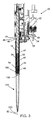
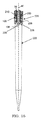
図1および図2は、ピペット装置20の例示的な実施形態、拡張式マンドレルコレット結合装置(拡張マンドレルコレット結合装置)100つまりピペットチップカプラの例示的な実施形態、および拡張式マンドレルコレット結合装置100を介してピペット装置20に取外し自在に結合される使い捨てピペットチップ220の例示的な実施形態を備えた、ピペット装置アセンブリ(ピペット装置組立体)10の例示的な実施形態を示す。
1 and 2 show an exemplary embodiment of a
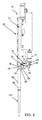
ピペット装置20
図2を参照して、ピペット装置20は、モータ28に動作可能に結合ないし接続され且つこれにより駆動されるプランジャ26を備えた吸引および分注(分配)用の装置24を支持する、本体22を有する。プランジャ26は、ピペット装置20の本体22の遠位(遠位側)つまり下側の端32から延びるプランジャシリンダ30内に存在する。
Referring to FIG. 2, the
ピペット装置20は吸引および分注(分配)用のシリンダ34をさらに備えている、このシリンダは、プランジャ26と軸方向に整列し且つプランジャ26の遠位の下側の位置において少なくとも一部がプランジャシリンダ30内に配置されている。吸引および分注用のシリンダ34は、拡張式マンドレルコレット結合装置100に取り付けるために遠位の取付けフランジ36内に遠位から移行し、この結合装置は次いで使い捨てピペットチップ200に取り外し自在に結合される。
The
図1、図3および図15を参照して、吸引および分注用のシリンダ34は内側の囲繞側壁38をさらに備え、この側壁はそれを通って延びる端部が開口した(開口端)ピペットチャネル40を画定する。端部が開口したピペットチャネル40は、吸引および分注用のシリンダ34の開口上端部42と開口下端部44との間でピペット装置アセンブリ10の長手方向チャネル軸80に沿って長手方向に延びて、プランジャ26と遠位の取付フランジ36に隣接する外部領域との間の開放連通を提供し、遠位の取付フランジ36は拡張式マンドレルコレット結合装置100の中央本体部材102に動作可能に接続されており、また拡張式マンドレルコレット結合装置100を介してチップ220と吸引および分注用のシリンダ34との間の開放連通を提供するために中央本体部材102は中央本体部材102を通って延びる端部が開口した(開口端)中央チャネル136を備える。
With reference to FIGS. 1, 3 and 15, the
ピストンまたはスクイズスリーブ46
Piston or squeeze
図3および図4を参照して、ピペット装置20は、近位(近位側)または上側の端48および遠位(遠位側)または下側の端50を有する中空ピストンつまりスクイズスリーブ46をさらに備える。スクイズスリーブ46は、プランジャシリンダ30と吸引および分注用のシリンダ34の両方を囲み、またスクイズモータ52に動作可能に結合されている。
Referring to FIGS. 3 and 4,
図4に示したように、ピペット装置アセンブリ10のスクイズモータ52は、装置20の本体22上に支持されると共に、リードスクリュー54に動作可能に結合ないし接続されてこれを駆動する。このスクリューは次いで軸方向に並進(並進移動)するリードナット56に結合され、このナットはスクイズリンケージ58に動作可能に結合される。スクイズリンケージ58は、スクイズリンケージアーム60を介してスクイズスリーブ46の近位または上側の端48に動作可能に結合されており、これにより、スクイズモータ52を第1の方向に回転させると、長手方向チャネル軸80(図3)に沿って遠位または垂直下方向にスクイズスリーブ46が直線的に軸方向に並進し、また続いてスクイズモータ52を第2の方向または反対方向へ回転させると、長手方向チャネル軸80(図3)に沿って下方向とは反対の近位または垂直上方向にスクイズスリーブ46が直線的な逆の軸方向並進をする。
As shown in FIG. 4, the
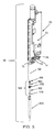
排出スリーブ62
図4を参照して、ピペット装置20は、使い捨てピペットチップ220をピペット装置20から排出するために使用される排出スリーブ62をさらに備えている。排出スリーブ62は、吸引および分注用のシリンダ34(図2)に対して軸方向に移動可能であり、近位または上側の端64、遠位または下側の端66、および排出スリーブアーム68を備えている。排出スリーブアーム68は、第1の端部が上側の端64に隣接して排出スリーブ62に取り付けられ、また反対側の第2の端部がプランジャ装置70の第1の端部に取り付けられる。
Referring to FIG. 4, the
図5に示したように、プランジャ装置70は、排出スリーブばね74の一端に当接する対向端面72を有し、このばねの反対側の端は装置20の本体22の上面部76に当接する。排出スリーブばね74は面72と面76の間に捕捉されてばね付勢(ばね負荷)され、プランジャ装置70および取り付けられたスリーブ62を正常ピペットチップ排出状態(正常にピペットチップが排出された状態)にバイアスする。
As shown in FIG. 5, the
正常ピペットチップ排出状態では、例えばピペットチップ220への結合に際して、排出スリーブ62を図2に示した後退状態(引っ込んだ状態)まで軸方向に押すために、排出スリーブのばねの力に打ち勝つための力を必要とする。図2にはさらに、ばね74の形状を保持し且つばね74の座屈を防するために、ばね74が中央ばねガイド部材78を囲んでいることが示されている。
In the normal pipette tip ejection state, for example, in order to push the
さらに、ばね74は、その弛緩の過程でスリーブ62によってピペットチップ220に及ぼされる力が、拡張式マンドレルコレット結合装置100からチップ220を排出するのを補助することができる寸法(大きさ)に構成される。
Furthermore, the
拡張式マンドレルコレット結合装置100および使い捨てピペットチップ220は、ピペット装置の他の実施形態で実施することができ、ピペット装置20の実施形態は、単なる一例であってこれに限定されない。
The expandable mandrel
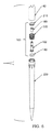
拡張式マンドレルコレット結合装置100
Expandable Mandrel
図5から図7を参照して、拡張式マンドレルコレット結合装置100は、細長い中央本体部材102、細長い中央本体部材102の遠位または下側の端部に支持された遠位または下側のエラストマー要素(ゴム状弾性体要素)140、細長い中央本体部材102を囲むように構成されると共に分割カラー(分割(セグメント化)されたカラー)200を有する拡張式コレット170、および環状ウェッジ(環状楔体)またはワッシャ210を備える。
5-7, expandable mandrel
環状ウェッジ210は、それを通る細長い中央本体部材102の上側部分を受容ないし支持するように構成されており、分割カラー200に隣接する拡張式マンドレルコレット170の内側上部に軸方向に移動自在な状態で置かれており、また分割カラー200は第1の外周(周径)を有する非拡張状態から第2の外周より大きい第2の外周(周径)を有する拡張状態まで環状ウェッジ210の中央本体部材102に対する軸方向の位置に応じて半径方向外向きに拡張し、図21に示した分離(非係合)状態から図29に示したようにピペットチップ220の内側に係合する。
The
細長い中央本体部材102
Elongated
より具体的には、図7と図8を参照して、拡張式マンドレルコレット結合装置100は、長手方向中心軸90に沿って近位または上側の環状端面104と遠位または下側の環状端面130との間に延びる、細長い中央本体部材102を備える。
More specifically, referring to FIGS. 7 and 8, the expandable mandrel
図8に示したように、中央本体部材102の上側の環状端面104は外側の面取りされた外縁106を備え、この外縁は細長い管状の上側シャンク部材108に移行し、このシャンク部材は遠位側で環状のテーパ部分110内に移行する。一つの実施形態において、シャンク部材108は、対応するネジ山を有する遠位の取付フランジ36にねじ込まれて組立られる。環状のテーパ部分110は、シャンク部材108から直径が減少し、また遠位側で筒状ネック部112に移行する。筒状ネック部112は遠位側で、筒状ネック部112の直径よりも大きな直径を有する筒状カラー(筒状環)114内に移行する。
As shown in FIG. 8, the upper
筒状カラー114には、筒状ネック部112の直径よりも大きな直径を有する下側の筒状の本体部材120が続いている。本体部材120は、筒状カラー114から、下側の筒状の本体部材120の直径よりも大きい直径を有する遠位の筒状ステム部面(筒状脚部面)124の上側環状肩部端または停止面122まで、遠位側に延びている。
Following the
同じく図8に示したように、筒状ステム部面124は遠位側で上側環状肩部端122から丸い端板126内に移行し、この端面は、上側面128と、遠位または下側の環状端面130によって画定される下側面とを有する。図示のように、端面126はステム部面124の直径よりも大きい直径を有し、遠位のステム部面124は拡張式マンドレルコレット結合装置100の遠位または下側の溝部132を画定する。
As also shown in FIG. 8, the tubular
図8および図15を参照して、細長い中央本体部材102は、上側環状端面104と下側環状端面130との間で長手方向中心軸90に沿って中央本体部材102を通って延びる端部が開口した(開口端)筒状の中央チャネルまたは通路136を画定する、内側筒状チャネル面134を備え、これにより、細長い中央本体部材102を通って、ピペット装置アセンブリ10の長手方向チャネル軸80に沿って長手方向に延びる端部が開口した(開口端)ピペットチャネル40までの、開放通路連通(開放通路による連通)が提供される。
Referring to FIGS. 8 and 15, the elongated
遠位のエラストマー要素140
Distal
図7にさらに示したように、拡張式マンドレルコレット結合装置100は、細長い中央本体部材102の遠位の端部において同軸状に支持された、遠位または下側のエラストマー要素140をさらに備えている。
As further illustrated in FIG. 7, the expandable mandrel
一つの実施形態において、図9を参照して、遠位のエラストマー要素140は環状本体142を有してなる。環状本体142は、中央開口146を画定する内面144、上面148、周辺外面150、および底面152を備える。中央開口146は、拡張式マンドレルコレット結合装置100の遠位の筒状ステム部面124を密接または緊密に囲む寸法(大きさ)であり、また図7に示されたように溝132内に存在すると共に円周状ないし環状で半径方向外方に端板126を越えて延びる形状に作られる。弛緩状態または非スクイズ(押し込まれていない、圧力が掛けられていない)状態では、遠位のエラストマー要素140は、図15に示したように、周方向に連続した略円形の断面積(断面領域)154を備える。
In one embodiment, referring to FIG. 9, the distal
スペーサ160
図10を参照して、拡張式マンドレルコレット結合装置100は、細長い中央本体部材102を囲むように構成または一体的に形成された、スペーサ160をさらに備える。図示のように、スペーサ160は、上端164と下端165との間に延びる筒状本体162を備える。筒状本体162は、本体162を通って延びる端部が開口した(開口端)通路168を画定する内側囲繞面166(図15)を備え、通路168は、細長い中央本体部材102の下側の筒状本体部材120に密接または緊密に囲む寸法(大きさ)に作られる。
Referring to FIG. 10, expandable mandrel
図7、図10および図15を参照して、スペーサ160はさらに拡張式マンドレルコレット170に囲まれるように構成されており、スペーサ160の上端164が取付フランジ36の遠位端に当接すると共に下端165が拡張式マンドレルコレット170の環状基部172の内側の環状肩部停止面177に当接し、環状基部172は細長い中央本体部材102の遠位の筒状ステム部124(図8)の遠位の環状肩部停止面122上に置かれる遠位側または下側の環状端部176をさらに備え、拡張式マンドレルコレット170を長手方向中心軸90に沿って中央本体部材102と同軸状に取付けないし固定する。
Referring to FIGS. 7, 10 and 15, the
図15および図16を参照し、および上記したように、拡張式マンドレルコレット結合装置100のシャンク部材108は吸引および分注用のシリンダ34の遠位の取付フランジ36内に嵌合するように構成され、拡張式マンドレルコレット結合装置100をピペット装置20に動作可能に結合すると共に拡張式マンドレルコレット結合装置100を介して使い捨てピペットチップ220をピペット装置20に取外し自在に結合し、長手方向のチャネル軸80と中央軸90は一致または共通する長手方向のチャネル軸を形成する。
Referring to FIGS. 15 and 16 and as described above, the
拡張式マンドレルコレット170
図7および図11を参照して、拡張式マンドレルコレット170は複数の周方向(円周状)に離間し上方に延びるコレットアーム180を備えており、これらアームは、下側の環状基部172に取付けられた端部184から、下側の環状基部172の軸方向上方に配置された分割カラー(分割(セグメント化)されたカラー)を画定する分割(セグメント化)された自由端200まで上方に移行する。複数の周方向に離間し上方に延びるコレットアーム180は、複数の周方向に離間し上方に延びる溝182の1つによって互いに分離されている。
Referring to FIGS. 7 and 11,
図11および図12に示したように、複数の上方に延びるコレットアーム180はそれぞれ、各上側アーム部190に移行する各下側アーム部186を備える。一つの実施形態において、複数の周方向に離間した下側アーム部186は略筒状に形成された囲繞下側本体部181を形成し、また複数の周方向に離間した上側アーム部190は、下側本体部181から半径方向外方および上方に移行し円錐台状に形成された囲繞上側本体部183を形成する。下側本体部181は、遠位または下側の環状基部172に対して僅かに上方にテーパ状または周径が増すように構成しても良い。
As shown in FIGS. 11 and 12, the plurality of upwardly extending
基部172
図11および図12を参照して、遠位または下側の環状基部172は、遠位または下側を向いたベース面171と、近位または上側を向いたベース面173とを備える。遠位を向いたベース面171は、下側の環状ベース部172の遠位または下側の環状基部端176で終端する、縮められた遠位または下側の端部環状ステム面(端部環状脚面)174内に下向きに移行する。ベース面171と基部172は、図14に示されたように縮められた遠位の端部環状溝178を画定する。
With reference to FIGS. 11 and 12, the distal or lower
図12および図15を参照して、下側の環状基部172は、図15に示したようにスペーサ160が取付けられた内側環状肩部停止面177内に上向きに移行する内側筒状面175をさらに備えている。さらに、内側筒状面175は中央本体部材102の環状肩部停止面122の真上の位置において中央本体部材102の下側の筒状本体部材120に密接に囲む内径を有する寸法(大きさ)であり、環状肩部停止面122は拡張式マンドレルコレット170の下側環状基部端176のための軸方向停止部を画定し、これにより、拡張式マンドレルコレット170は細長い中央本体部材102を中心としてその上および周りに取付けられる。
Referring to FIGS. 12 and 15, lower
下側アーム部186
図11に示したように、下側アーム部186は、周方向に離間し且つ下側環状基部172に取付けられた、遠位または下側の端部184を備える。図12に示したように、下側アーム部186はさらに、内側の環状で凹状の分割(セグメント化)された面または溝191と外側の半径方向外方に延びる環状に分割(セグメント化)された停止ディスク部194とを有する中間アーム部を画定する、上側の端部を備える。
As shown in FIG. 11,
図11および図12を参照して、分割された停止ディスク部194は、環状の分割された停止ディスク部を画定する複数の周方向に離間した上方に延びるコレットアーム180の中間アーム部の外側を囲み且つこの外側から半径方向に延びている。
Referring to FIGS. 11 and 12, the
図12に示したように、分割された停止ディスク部194の各々は、近位または上方を向いた停止ディスク面198、および遠位または下側を向いた停止ディスク面196を備える。さらに、複数の下側アーム部186は、内側の筒状または内側の分割された面188を備え、この面は細長い中央本体部材102を囲むスペーサ160を密接に囲む内径を備えた寸法(大きさ)である。
As shown in FIG. 12, each of the segmented
内側の分割された面188の遠位または下側の端は、上記で詳述したようにスペーサ160のための停止面を提供する内側環状肩部停止面177内に半径方向内向きに移行する。内側の分割された面188の近位または上側の端は、内側の環状凹状の分割された面または溝191内に移行する。
The distal or lower end of the inner
上側アーム部190
図11および12を参照して、周方向に離間して配置された複数の上側アーム部190は各下側アーム部186から上方および半径方向外方に移行すると共に下側アーム部186から上方および半径方向外方に配置された複数の自由端199内に終端し、複数の自由端199は分割カラー200を画定する半径方向外方に突出するセグメントを有しており、各セグメントは外側の外方を向いた面202を備え、この面は一つの実施形態においてピペットチップの例示的な実施形態の円弧状(弓状)の溝に対応する外向きに丸みを帯びた形状または円弧状(弓状)の形状である。
Referring to FIGS. 11 and 12, a plurality of circumferentially spaced
従って、上側アーム部190は分割された停止ディスク194から分割カラー200を画定する複数の半径方向外方に突出したセグメントまで上方および半径方向外方に移行し、分割カラー200は図7に示されたように拡張式マンドレルコレット結合装置100の長手方向中心軸90を囲むように構成される。
Thus, the
さらに、複数の周方向に離間し半径方向外方および上方に延びる上側アーム部190は、環状ウェッジ210(図7)の近位に傾斜した環状の側面216と相補的である傾斜し分割された内面を形成する内面192をそれぞれ備えるセグメントを含んでおり、これらはそれぞれZ軸に対して遠位に減少する周径(円周)を備え、また上側アーム部190の内面192は細長い中央本体部材102に対して半径方向外方および上方に延びる円錐形状の隙間204を形成する(図15)。
Further, a plurality of circumferentially spaced, radially outwardly and upwardly extending
より詳しくは、図15に示したように、複数の周方向に離間した上側アーム部190の上方および半径方向外方に傾斜した内面192は、上側アーム部190の内面192と、取付けフランジ36の下側部分およびスペーサ160の上側部分の組合わせ部との間に、遠位に先細り(テーパ状)の円錐状の隙間204を画定する。テーパ状で円錐状の隙間204は環状ウェッジ210の下側部分を受容するように構成されており、これにより、環状ウェッジ210の環状楔形状または傾斜した外側面216が、分割カラー200を画定する突出したセグメントを支持する複数の自由端199の内面192に当接する。
More particularly, as shown in FIG. 15, the upper and radially outwardly sloping
環状ウェッジ210
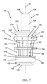
図7、図13、および図15を参照して、環状ウェッジ210は、周方向に連続した、略くさび形の断面211を有する弾力的な(弾性のある)くさび形の環状本体を備える。環状ウェッジ210は、本体102を移動可能に囲むように構成された環状ウェッジ210を通って延びる中央環状開口213を画定する、中央内側環状面212を備える。
Referring to FIGS. 7, 13 and 15,
また、環状ウェッジ210は、LLD回路364のLLD回路リング端366との電気接点スイッチを形成するように構成され、および中央内側環状面212から囲繞外側端面215まで半径方向外方に延びる、頂部平坦円形面214を備えている。
Also, the
さらに、環状ウェッジ210は半径方向外方に近位に傾斜した側面216を備える。この側面は底部環状端218から、半径方向外方に延び且つ囲繞外縁面215で終端する環状周縁リップ219の下側まで、半径方向に上方および外方に延びる、したがって、半径方向外方に近位に傾斜した側面216は遠位にテーパ状のくさび形の面216を画定する。
Furthermore, the
図15に例示したように、環状ウェッジ210の中央環状開口213は遠位の取付けフランジ36および細長い管状の上側シャンク部材108の通過を許容する寸法(大きさ)に作られており、これにより、環状ウエッジ210の半径方向外方に近位に傾斜した面216が、複数の半径方向外方に突出したセグメント200の内面192に当接して着座することが可能になり、この結果、環状ウエッジ210が遠位側に軸方向に並進することで、拡張式マンドレルコレット170の半径方向外方に突出するセグメント200の半径方向の突出、および続く環状ウェッジ210の近位側への並進が生じ、拡張式マンドレルコレット170の半径方向外方に突出したセグメント200の半径方向の後退(収縮)が起きる。
As illustrated in FIG. 15, the central
図15にさらに示したように、拡張式マンドレルコレット結合装置100のシャンク部材108は吸引および分注用のシリンダ34の遠位の取付フランジ36内に嵌合するように構成され、拡張式マンドレルコレット結合装置100をピペット装置アセンブリ10のピペット装置20に動作可能に結合して、長手方向チャネル軸80および長手方向中央軸90は一致または共通の軸線を形成する。
As further shown in FIG. 15, the
拡張式マンドレルコレット170はさらに、スクイズスリーブ46により提供される力の下で環状ウェッジ210が軸方向下方に移動するときに、分割カラー200を、図7に概略的に示した第1の周径(円周)を有する非拡張状態から、図14に概略的に示した第1の周径(円周)よりも大きい第2の周径(円周)を有する拡張状態まで、半径方向外方に拡張するように構成される。
The
スクイズモータの動作 Squeeze motor operation
図15を参照して、拡張式マンドレルコレット結合装置100は遠位の装着フランジ36内に嵌合するように構成され、環状ウェッジ210の頂部平坦円形面214がスクイズスリーブ46の遠位側の端50に隣接して配置される。
従って、図4および図15を参照して、スクイズモータ52を第1の方向に動作(作動)させることでスクイズスリーブ46の遠位または垂直方向下向きの直線的な軸方向並進が生じ、環状ウェッジ210の頂面214に軸方向に力が加えられ、この結果、遠位にテーパ状のくさび面216が円錐状の隙間204内にさらに軸方向に滑り落ちる(押し込まれる)ようになり、遠位にテーパ状のくさび面216が複数の半径方向外方に突出したセグメント200の内面192に押し付けられ、上方に延びるコレットアーム180のばね張力に抗してセグメント200の外側の半径方向外向きの面202(図11)を半径方向外方に押出し、以下に説明する図29に示されたように使い捨てピペットチップ220の溝246を画定する面244の形態のピペットチップの第1の作用面と接触させる。
Referring to FIG. 15, expandable mandrel
Thus, referring to FIGS. 4 and 15, actuating the
次に、スクイズモータ52を、第1の方向とは反対の第2の方向に動作(作動)させることで、スクイズスリーブ46の遠位側の端50が図15に示すホーム位置まで戻り、このため環状ウェッジ部材210が軸方向に上に摺動し、その結果、上方に延びるコレットアーム180に蓄積されたポテンシャルエネルギー(位置エネルギー)が開放ないし放出され、これにより、複数の半径方向外方に突出するセグメント200の外側の半径方向外方に向いた面202が使い捨てピペットチップ220の溝246から後退ないし引っ込む。
Next, the
ピペットチップ220
図2および図16に示したように、および上記したように、拡張式マンドレルコレット結合装置100は、使い捨てピペットチップ220とピペット装置アセンブリ10のピペット装置20との間の開放連通状態の結合を提供する。
As shown in FIGS. 2 and 16, and as described above, the expandable mandrel
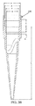
図16から図18を参照して、および一つの実施形態において、使い捨てピペットチップ220は、中央長手軸224を有する細長い管状ピペットチップ本体222を備える。ピペットチップ本体222は、近位または上側の環状端面228と、遠位または下側の環状端面230との間で、中央長手軸224に沿って長手方向に延びる、細長い囲繞側壁226を備え、環状端面228および環状端面230は、囲繞する(周囲を取り囲む)開口した近位の環状端232および遠位の環状端234をそれぞれ画定する。細長い囲繞側壁226は、開口した上側の環状端232と開口した下側の環状端234との間でピペットチップ本体222の中央長手軸224に沿って長手方向に延びるピペットチップ通路開口238を画定する、内面236を備える。
Referring to FIGS. 16-18, and in one embodiment,
したがって、結合装置100がピペット装置20とピペットチップ220との間に結合されているときに、ピペットチップ通路開口238は、開口した遠位の環状端234の外側の領域から(図18)ピペットチップ220を通ってピペット装置チャネル40(図15)まで、拡張式マンドレルコレット結合装置100の中央チャネル136を介して(図16)、開放連通を提供する。この継手構成において、ピペットチップ本体222の中央長手方向軸224は、ピペット装置20の長手方向チャネル軸80と同じの広がりを持つ(同一の領域を占める)。
Thus, when the
第1内面セクション First inner section
図18を参照して、および一つの例示的な実施形態において、細長い囲繞側壁226の内面236は最上部の環状の面取りされた内面(環状面取り内面)240を備え、この内面は、ピペットチップ220の近位の環状端面228から遠位側に半径方向内方に延び且つ第1の直径を有する第1の実質的に筒状の内面セクション242内に移行することで終結する。
Referring to FIG. 18 and in one exemplary embodiment, the
溝を画定する軸方向に円弧状(弓状)の円周面 Axially arced (arcuate) circumferential surface defining the groove
図18に示したように、および1つの例示的な実施形態において、第1の実質的に筒状の内面セクション242は、円周環状溝246を画定する細長い囲繞側壁226内に形成された軸方向に円弧状(弓形)の円周内面(内周面)244を備える。環状溝246は、第1の実質的に筒状の内面セクション242を、上側の第1の実質的に筒状の内面部分と、実質的に等しい直径である下側の第1の実質的に筒状の内面部分とに分割する。従って、環状溝246は、長手方向断面が円弧状面である、第1の実質的に筒状の内面セクション242の円周状ないし環状で半径方向外方に延びる凹んだ形状の内面中断部を提供する。円弧状の内周内面244も、以下に説明するように、別の断面で構成される。また、一つの実施形態において、第1の実質的に筒状の内面セクション242は、円周環状溝246を画定する円弧状の円周内面(内周面)244を欠いている。
As shown in FIG. 18, and in one exemplary embodiment, the first substantially cylindrical
図18および19を参照して、環状溝246を画定する軸方向に円弧状の円周内面(内周面)244は、軸方向に円弧状の円周内面(内周面)244の上側の軸方向に円弧状の円周面セクタ部250内に遠位側に移行する、上側の環状移行端248を備えている。上側の軸方向に円弧状の円周面セクタ部250は、続いて、軸方向に円弧状の円周面244の下側の軸方向に円弧状の円周面セクタ部252内に遠位側に移行する。次に、下側の軸方向に円弧状の円周面セクタ部252は下側の環状移行端254で終端する。
Referring to FIGS. 18 and 19, the axially arc-shaped circumferential inner surface (inner circumferential surface) 244 defining the
上側の軸方向に円弧状の円周面セクタ部または上側部250は、ピペットチップ220の中央長手軸224(図17)に対する半径として、上側の環状移行端248から環状溝246の最大半径まで増加する半径を、環状溝246に提供し、中央長手軸224は環状溝246の周方向環状中心を画定する。下側の軸方向に円弧状の円周面セクタ部または下側部252は、ピペットチップ220の中央長手軸224に対する半径として、環状溝246の周方向環状中心を画定する最大半径から下側の環状移行端254まで減少する半径を、環状溝246に提供する。
The upper axially arcuate circumferential surface sector or
第2の内面セクションおよび環状肩停止面 Second inner section and annular shoulder stop surface
図18に例示したように、第1および第2の実質的に筒状の内面セクション242、262の間に置かれた、近位に面した半径方向内方に延びる環状肩部座面または軸方向停止面260形成するために、第1の実質的に筒状の内面セクション242の軸方向に遠位側には、第1の実質的に筒状の内面セクション242の第1の直径より小さい第2の直径を有する第2の実質的に筒状の内面セクション262がある。
As illustrated in FIG. 18, the proximally facing radially inwardly extending annular shoulder seating surface or shaft located between the first and second substantially cylindrical
1つの例示的な実施形態において、近位に面する軸方向停止面260は、実質的に平坦ないし平面であり、また図17に示したようにピペットチップ本体222の中央長手軸224に対してほぼ垂直である。
In one exemplary embodiment, the proximally facing
第3の内面セクションおよび密封座部(シーリングシート) Third inner section and sealing seat (sealing sheet)
図18および19に同様に示したように、第2の実質的に筒状の内面セクション262の軸方向に遠位側には、セクション262の第2の直径より小さい第3の直径を有する第3の実質的に筒状の内面セクション272がある。
As also shown in FIGS. 18 and 19, on the axially distal side of the second substantially cylindrical
第2のセクション262と第3のセクション272との間には、円周状ないし環状で半径方向内方に傾斜し且つ遠位に延びる遠位の作用面270を画定する円錐台形で環状の密封座面(シール用座面)または停止面270が介在する。円錐台形で環状の密封座面270は、第2の実質的に筒状の内面セクション262と円錐台形で環状の密封座面270との間の環状境界を画定する上側の環状密封座端266を備える。さらに、円錐台形環状密封座面270は、円錐台形で環状の密封座面270と第3の内面セクション272との間の環状境界を画定する下側の環状密封座部端268を備え、上側の環状密封座端266の直径は、下側の環状密封座端268の直径よりも大きい。
Between the
したがって、円錐台形で環状の密封座面270は、第2の実質的に筒状の内面セクション262と第3の実質的に筒状の内面セクション272との間に介在された、円周状ないし環状で半径方向内方に傾斜し且つ遠位に延びる第2の作用面または密封座面270を画定する。
Thus, the frusto-conical annular
例示したように、密封座面270は中央長手軸224に対して鋭角に配置され、この鋭角は中央長手軸224に対する鋭角な密封座面の角度を画定する(図17)。一つの実施形態において、中央長手軸224に対する好適な鋭角な密封座面の角度は約15度から約35度であり、好ましい角度は約25度である。図41に示したように、中央長手軸224に対する別の密封座面2270の鋭角の密封座面の角度は約90度である。
As illustrated,
下側内面部 Lower inner surface
図18にはさらに、第3の実質的に筒状の内面セクション272に続いて第4の内面セクション274があり、これには第5の内面セクション275が遠位側に続いていることが示されている。
FIG. 18 further shows a third substantially cylindrical
一つの例示的な実施形態において、第4の内面セクション274は、第3の実質的に筒状の内面セクション272の遠位の環状端276から第5の内面セクション275の近位の環状端278まで、直径が遠位側にテーパ状(先細り)または減少する。一方、第5の内面セクション275は、第5の内面セクション275の近位の環状端278から、液浸の対象となるピペットチップ220の開口した遠位の環状端234まで、直径が遠位側にテーパ状または減少する。さらに、一つの例示的な実施形態例では、第5の内面セクション275は、第4の内面セクション274より大きなテーパ状を有する(先細りの程度が大きい)。
In one exemplary embodiment, the fourth
外側長手方向リブ Outer longitudinal rib
図17を参照して、ピペットチップ220の一つの例示的な実施形態は複数の周方向ないし円周状に離間され長手方向に延びる外側リブ280を備えており、これらリブは、近位の環状端面228の周囲に隣接する管状のピペットチップ本体222上に配置されると共に、そこから、図18に示したように第3の実質的に筒状の内面セクション272に隣接する囲繞側壁226の外部領域まで、長手方向に外側に延びる。
Referring to FIG. 17, one exemplary embodiment of the
一つの例示的な実施形態において、
複数の周方向に離間し長手方向に延びる外側リブ280は、ピペット本体222が例えば支持面隙間開口284を介して通過する支持面282の上または内側において、ピペット本体222を支持するために利用することができる。支持面282の一つの例示的な実施形態は、これに限定されないが、当該技術分野において公知のチップラック(ピペットチップ用ラック)の形状のラボウェアの形態でもよく、本実施形態でもこれが用いられる。
In one exemplary embodiment,
A plurality of circumferentially spaced, longitudinally extending
自動分注ワークステーションまたはシステム Automatic dispensing workstation or system
図5および図20を参照して、および1つの使用および動作例において、1つ以上のピペット装置アセンブリ10は、自動分注(自動ピペッティング)ワークステーションまたはシステム300に採用される。このシステムは、これに限定されないが、一般的には、容器間での液体のプログラムされた移送(所定の手順での移送)を提供するものであり、例えば、容器間での液体のプログラムされた移送を実行するための、ピペット装置20によって動作可能に支持される拡張式マンドレルコレット結合装置100に1つ以上の使い捨てピペットチップ220を取付けおよび排出するプロセスを有してなる。
Referring to FIGS. 5 and 20, and in one use and operation example, one or more
一つの例示的な実施形態において、自動分注ワークステーション300は、一般的に、水平に配置されたワークステーションデッキ304の垂直上方に少なくとも1つのピペット装置アセンブリ10を保持する、ロボットガントリー(直交ロボット)302を備える。ピペット装置アセンブリ10は、単チャネルのピペットヘッド(分注ヘッド)またはマルチチャネルのピペットヘッドを備えることができる。
In one exemplary embodiment, the robotic dispensing workstation 300 generally holds at least one
また、ロボットガントリー302は典型的には2つまたは3つの自由度を提供し、3つの自由度は、X軸を規定する軸に沿った縦(経度)方向の並進、Y軸を規定する軸に沿った横(緯度)方向の並進、およびZ軸を規定する軸に沿った垂直(上下)方向の並進からなり、これによりピペット装置アセンブリ10は上記デッキの長さ(X軸)及び幅(Y軸)に沿って、およびこれらに対して上下(Z軸)に移動することができる。2つの自由度を持つことで、ロボットガントリーは、典型的には、ピペット装置アセンブリ10を上下方向、および縦方向と横方向のいずれかに並進する機能を備える。
Also, the robot gantry 302 typically provides two or three degrees of freedom, the three degrees of freedom being a longitudinal (longitude) translation along an axis defining the X axis, an axis defining the Y axis Translation along the axis, and vertical (up and down) translation along the axis defining the Z axis, such that the
一つの例示的な実施形態では、自動分注ワークステーション300は、主制御装置(メインコントローラ)306、ピペット軸制御装置308、および主制御装置306とピペット軸制御装置308とピペット装置アセンブリ10とに電力を供給する電源310をさらに備える。
In one exemplary embodiment, the automatic dispensing workstation 300 includes a main controller (main controller) 306, a pipette axis controller 308, and the main controller 306, the pipette axis controller 308, and the
さらに、および1つの例示的な実施形態において、以下に詳述する使い捨てピペットチップ220の取付けおよび排出(結合および分離)プロセスのようなピペット装置アセンブリ10の関連プロセスプロトコルを含むロボットガントリー302およびピペット装置アセンブリ10の制御のために、コンピュータ/コントローラ320をワークステーション300と共に使用し、またメインコントローラ306やピペット軸コントローラ308と通信させることもできる。
In addition, and in one exemplary embodiment, a robotic gantry 302 and pipetting apparatus including associated process protocols of the
一つの例示的な実施形態において、コンピュータ/コントローラ320は、典型的には、プロセッサデバイスまたは中央処理装置(CPU)322、ハードウェア読み出し専用メモリデバイス(ROM)324、ハードウェアメインメモリデバイス(RAM)326、オペレーティングシステム332やピペット装置アセンブリ10用として保存されたユーザ定義プロセス336のようなソフトウェア334を有する非一時的コンピュータ可読媒体またはメモリ330を有してなるハードウェア記憶装置328、ユーザディスプレイ338、ユーザ入力装置340、入力インタフェース342、出力インタフェース344、通信インタフェース装置346、およびコンピュータ/コントローラ320のデバイス間の通信を可能にする1つ以上の導体または通信経路を備えるシステムバス348を備えている。コンピュータ/コントローラ320は、LANおよび/またはサーバ350に動作可能に接続しても良い。電源352は、コンピュータ/コントローラ320に電力を供給する。
In one exemplary embodiment, the computer / controller 320 is typically a processor device or central processing unit (CPU) 322, a hardware read only memory device (ROM) 324, a hardware main memory device (RAM) Hardware storage 328 comprising a non-transitory computer readable medium or memory 330 with software 334 such as operating system 332 and user defined process 336 stored for the
ソフトウェアを含む上記で記述した自動分注ワークステーション300の例は、現在、アメリカ合衆国、ネバダ州 89502、Reno、Energy Way 4970にある本特許出願の譲受人であるHamilton Companyによって製造され、販売されている。 An example of the above-described automated dispensing workstation 300, including software, is currently manufactured and sold by Hamilton Company, assignee of the present patent application in Energy Way 4970, Reno, Nevada 89502, United States of America .
拡張式マンドレルコレット結合装置へのピペットチップのピックアッププロセス Pickup process of pipette tip to expandable mandrel collet binding device
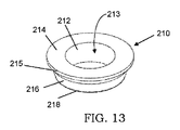
図21から31は、ピペットチップのピックアッププロセスの連続的な段階の例示的な実施形態の詳細を示しており、特に、ピペット装置20によって動作可能に支持された拡張式マンドレルコレット結合装置100へのピペットチップ220の固定取付けを行う方法を示したものである。上述したように、および1つの例示的な実施形態例において、ピペットチップ220は支持面282によって支持されてもよい。
21 to 31 show details of an exemplary embodiment of successive stages of the pipette tip pick-up process, in particular to the expandable mandrel
図21に示したように、拡張式マンドレルコレット結合装置100はピペット装置20に接続されており、コマンド(命令、指令)に応じて、結合装置100は、ピペットチップ220の開口した近位の端232の上方に配置され、それらの中央長手軸はそれぞれZ軸に沿って整列される。排出スリーブ62はイジェクト位置(排出位置)にあり、スクイズスリーブ46は非スクイズ位置にあり、拡張式マンドレルコレット170は弛緩状態にあり、および遠位のOリング140は非スクイズ状態にある。
As shown in FIG. 21, the expandable mandrel
次に、図22は拡大マンドレルコレット結合装置100がZ軸に沿ってピペットチップ220内に下降する状態を示しており、結合装置100の遠位のエラストマー支持部を下げ、ピペットチップ220の内側の筒状の近位の端部内を通過させ、遠位のOリング140をチップ220の環状シーリング座部または停止面270と接触させる一方、ピペットチップ220の上向きの環状の肩座部または停止面260と停止ディスク194の下向きの軸方向の停止ディスク面196とが係合ないし接合する前は遠位のOリング140は非スクイズ状態ないし非圧縮状態に維持される。
Next, FIG. 22 shows the enlarged mandrel
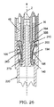
次に、図23は、結合装置100がさらにZ軸に沿って下方に移動した様子を示す。そして、図23から図25を参照して、スクイズスリーブ46はZ軸に沿って下方に移動してLLD回路リング端366を押し、このリング端(リング状端部)は拡張式マンドレルコレット170の上に載った環状ウェッジ210の頂面214に接触してこれを押し、一方、ピペットチップ220の停止面260と停止ディスク194の軸方向の停止肩面196とが嵌合ないし接合する前では、複数の半径方向外方に突出したセグメント200が図24に詳細に示したように非拡張状態に維持され、図25に詳細に示したように遠位のOリング140が非圧縮状態に維持され、これにより、図23に詳細に示したようにピペットチップ220の停止面260と、膨張式マンドレルコレット170の停止ディスク194の軸方向停止肩面196との間に隙間298が維持される。
Next, FIG. 23 shows how the
次に、図26はスクイズスリーブ46がZ軸に沿ってさらに下方に移動した状態を示したものであり、環状ウェッジ210を複数の半径方向外方に突出したセグメント200の内面192に対して押し、これらセグメントを半径方向外方に押し出し、図27に詳しく示したように複数の半径方向外方に突出したセグメント200の外側の半径方向外向きの丸い面202を使い捨てピペットチップ220の溝246の上側の軸方向に円弧状の円周面セクタ部250に当接させて、複数の半径方向外方に突出したセグメント200を溝246内に押し込みまたは押しつけるプロセスを開始し、および最初は溝246を画定する軸方向に円弧状の円周内面(内周面)244の上側の軸方向に円弧状の円周面セクタ部250に当接させる。図26に示したように、また図27に詳しく示したように、複数の半径方向外側に突出したセグメント200が溝246内に延びるまたは突出する動きによって軸方向上向きの力が発生し、これがピペットチップ220を引き上げるプロセスを開始させ、ピペットチップ220の環状肩部座面260を停止ディスク194の軸方向の停止肩面196に着座させ隙間298(図23)を閉じるプロセスが開始されて、図28に詳しく示したようにチップ220の密封座部または停止面270で遠位のOリング140が圧縮される。
Next, FIG. 26 shows the
図29は、スクイズスリーブ46が、それが所定の位置にロック(固定ないし係止)されるまでZ軸に沿って設定された所定の長さだけ下方に移動することで、環状ウェッジ210がスクイズスリーブ46によって停止され所定位置にロックされたことを示す。
FIG. 29 shows that the
この結果、複数の半径方向外方に突出したセグメント200は図30に例示されるように半径方向に所望の距離または値まで拡張され、拡張式マンドレルコレット結合装置100の軸方向停止肩面196がピペットチップ220の環状肩部座面260に完全に着座し、2つの面196、260の着座はZ軸に実質的に垂直なX軸に沿っており、これら2つの軸の間に垂直なデータムが形成される。
As a result, the plurality of radially outwardly projecting
同時に、遠位のOリング140をチップ220の環状シーリング座面270に着座させるために、遠位のOリング140は図31に例示されるように所望の距離または値まで圧縮されてその断面が最終的に圧縮された非円形の形態になり、これにより、ピペット装置20によって動作可能に支持された拡張式マンドレルコレット結合装置100へのピペットチップ220の固定取付けによる結合が完了する。
At the same time, in order to seat the distal o-
上記で詳述した固定取付けプロセスの完了後、複数の半径方向外方に突出したセグメント200と遠位のエラストマー要素140とが組み合わされて機能する、流体密封(流体密封シール)を提供するセグメントおよび密封結合が生成され、複数の半径方向外方に突出したセグメント200は少なくとも一部が周方向の溝246内に収容されると共に少なくとも一部が周方向の溝246を画定する円周状で円弧状の内面244(図18)上に着座し、および遠位のエラストマー要素140はピペットチップ220の面270を密封ないしシールし、一つの実施形態において面270は半径方向内方に傾斜し且つ遠位側または下方に延びる面を提供する。
A segment that provides a fluid tight seal (fluid tight seal) in which the plurality of radially outwardly projecting
したがって、複数の半径方向外方に突出したセグメント200は、半径方向外方に移動して周方向の溝246(図18)と係合しチップ220と結合すると共に、環状ウェッジ210の移動に応じてチップ220を離脱(取り外し)ないし解放するために半径方向内方に移動する。環状ウェッジ210を軸方向下方に動かすための力を加えることで複数の半径方向外方に突出したセグメント200が半径方向外方の位置に押され(付勢され)、また環状ウェッジ210上の力を解放することで複数の半径方向外方に突出したセグメント200を支持する片持ちアーム180(図11)からのエネルギーの放出がなされ、この結果、セグメントが半径方向外方の位置から半径方向内方の位置まで跳ね返る。
Thus, the plurality of radially outwardly projecting
使い捨てピペットチップ排出プロセス Disposable pipette tip ejection process
図21から図31は、逆に、ピペット装置20によって動作可能に支持された拡張式マンドレルコレット結合装置100からピペットチップ220を排出する例示的な方法またはプロセスの連続的な段階を詳細に示したものである。このチップ排出プロセスシーケンスは、逆である以外は、取り付けまたはチップのピックアップ固定プロセスシーケンスに類似しており、また図34は、排出プロセスの間にチップ220を取り外すのを助ける力を提供する圧縮された遠位のOリング140における遠位のOリング軸方向力成分を示したものである。
21-31, in turn, show in detail the sequential steps of an exemplary method or process of ejecting the
一つの例示的な実施形態において、排出プロセスは次のステップを有してなる。
(1) チップを、廃棄物容器(コンテナ)のような、それが処分される(捨てられる)場所に位置決めする。
(2) スクイズスリーブ46を上方に移動する。すると、環状ウェッジ210からの力が解放され、この結果、この力が複数の半径方向外方に突出したセグメント200からも同様に解放されてチップ220内の溝246からの後退が可能となり、遠位のOリング140は貯蔵された弾性ポテンシャルエネルギーまたはばねエネルギーをチップ220に対する力として放出し始め、およびばね付勢された排出スリーブ62がチップ220を同様に押してそれを押し出し、この結果、チップは複数の半径方向外方に突出したセグメント200から離脱ないし解放され始める。
(3) スクイズスリーブ46の上方への移動を継続する。すると、複数の半径方向外方に突出したセグメント200はチップ220内の溝246からの後退を続け、および遠位のOリング140およびばね付勢された排出スリーブ62がチップ220を押してそれを押し出し、チップ220は半径方向外方に突出した複数のセグメント200から離脱ないし解放され続ける。および
(4) スクイズスリーブ46をその最上部位置へ移動させることをさらに続ける。すると、複数の半径方向外方に突出したセグメント200は、それらの元の引込んだ自由状態に戻り、チップ220内の溝246から完全に外れ、遠位のOリング140は元の形状に戻り、ばね付勢された排出スリーブ62がチップ220を押す。これは、ばね付勢された排出スリーブ62によってチップがカプラ100から押し出され、ばね付勢された排出スリーブ62が完全に広がる(拡張する)まで続けられる。
In one exemplary embodiment, the evacuation process comprises the following steps.
(1) Position the chip in a place where it is disposed of (discarded), such as a waste container (container).
(2) Move the
(3) Continue moving the
上記を参照して、このようなチップ取り付けおよび排出プロセスは、広範囲な機械的および/または自動的に駆動されるピペット形式およびデザインのものに適用可能であることは当業者であれば理解できる。 With reference to the above, it will be understood by those skilled in the art that such tip attachment and ejection processes are applicable to a wide range of mechanically and / or automatically driven pipette types and designs.
結合力および排出力 Coupling force and discharge force
図32は、拡張式マンドレルコレット結合装置100の複数の半径方向外方に突出したセグメント200の図式的なベクトル図を例示したものであり、これらセグメントは当初は(初期状態では)溝246内に延びて(広がって)おり、複数の半径方向外方に突出したセグメント200の半径方向に丸い面202は、セグメントの半径の中心より上方のチップ溝の上側角に接触し、これによりピペットチップ220を上方に引っ張る軸方向上向きの力が生じる。図32に示したように、複数の半径方向外方に突出したセグメント200の各々に対するセグメント力(Fsegment_resultant)は、軸方向力(Fsegment_axial)成分と半径方向力(Fsegment_radial)成分の2つの成分からなる。
FIG. 32 illustrates a schematic vector diagram of a plurality of radially outwardly projecting
複数の半径方向外方に突出したセグメント200がセグメント半径(図33の寸法Z)の中心の上方にあるチップ溝の上側角に接触している限り、Fsegment_axialは、セグメント半径の中心と溝の角との間の距離が増加するにつれて増大する。従って、チップのピックアッププロセスの開始時にはセグメントの軸方向力(Fsegment_axial)は、図32に例示し、および図33に詳しく示したように、小さく始まり、また図34に示したようにチッププロセスの終わりにはその最大値まで増大する。
As long as the plurality of radially outwardly projecting
図33を参照して、Z/Rの比はSIN(ω)と等しく、またSIN(ω)は(Fsegment_axial)/(Fsegment_resultant)に等しい。この結果、(Fsegment_axial)は(Fsegment_resultant)にZ/Rの比を掛けたものに等しい。これから、結果として、(Fsegment_axial)はZが増加するにつれて増大する。 Referring to FIG. 33, the ratio of Z / R is equal to SIN (ω), and SIN (ω) is equal to (Fsegment_axial) / (Fsegment_resultant). As a result, (Fsegment_axial) is equal to (Fsegment_resultant) multiplied by the ratio of Z / R. From this, as a result, (Fsegment_axial) increases as Z increases.
図34を参照して、セグメントの軸方向力(Fsegment_axial)は停止ディスク194をチップ220のシート(座部)260に着座させると共にOリングの軸方向力(Fdistal_ring_axial)に打ち勝ち且つ遠位のOリング140を圧縮するのに必要な力を提供する。Oリング140は圧縮された結果生じるOリング力(Fdistal_ring_resultant)を有し、このOリング力は、軸方向成分(Fdistal_ring_axial)と半径方向成分(Fdistal_ring_radial)の2つの成分を有する。また、セグメントの半径方向力(Fsegment_radial)はセグメントをチップ溝246(図18)内にロックするために必要な半径方向の力を提供し、また遠位のOリングの半径方向の力成分(Fdistal_ring_radial)は、チップに対して密封(シール)を維持するために必要な半径方向の力を提供する。さらに、セグメントが溝に入るときにFsegment_axialを増加させる(寸法Zを増加させる)チップ溝に対するセグメントの形状は、Oリングの軸方向力(Fdistal_ring_axial)に打ち勝つのに役立ち、この結果、遠位のOリング140を所望の程度まで完全に圧縮できる。さらに、遠位のOリングの軸方向の力成分(Fdistal_ring_axial)は、排出プロセス中にチップ220を取り外すのを助ける力を提供する。
Referring to FIG. 34, the axial force (Fsegment_axial) of the segment causes the
位置合わせ、整列(アライメント)/位置ずれ(ミスアライメント) Alignment, alignment (alignment) / misalignment (misalignment)
カプラ100の軸方向の肩面196およびチップ220の軸方向の肩部座面260は、正しいチップ位置合わせのために重要である。したがって、カプラ100およびチップ220は、複数の半径方向外方に突出したセグメント200が軸方向の肩面196と軸方向の肩部座面260を一緒に押して、位置ずれを排除ないし防止するように構成される。これら肩部と肩面が適切に嵌合ないし噛み合わない場合、特にそれらが傾いている場合には、位置ずれ誤差(E)が大きくなる可能性があるからである。
The
例えば、図35および図36に示したように、位置ずれ角(θ)、チップの軸方向距離(D)、および位置誤差(E)の間の関係は、E=D×TAN(θ)である。例えば、位置ずれ角(θ)が2度でチップの軸方向距離が90ミリメートルの場合、位置誤差(E)は3.14ミリメートルとなる。これは、典型的な位置誤差の公差が典型的にはプラスまたはマイナス0.5ミリメートルであることを考慮すると、非常に大きいと考えられる。 For example, as shown in FIGS. 35 and 36, the relationship between the misalignment angle (θ), the axial distance of the chip (D), and the positional error (E) is E = D × TAN (θ) is there. For example, if the misalignment angle (θ) is 2 degrees and the axial distance of the chip is 90 mm, the position error (E) is 3.14 mm. This is considered to be very large, considering that typical positional error tolerances are typically plus or minus 0.5 millimeters.
図37は軸方向の肩面196と軸方向の肩座部260とが同一平面(同じ高さ)で互いに接触した正しいチップ位置合わせがされた状態を示しており、正しい位置合わせが提供されると共に、チップの座部260から遠位の端230までのチップの軸方向距離Dが一定に維持され、垂直方向または軸方向の軸Zおよび縦方向の軸Xに沿ったピペットチップの端230の既知で制御された距離が確立される。これは、ピペット装置が小穴や少量の液体を対象とすることを可能にするために重要である。さらに、ピペットチップの距離が既知で固定であるのでより少量の液体を移送することができ、液体292をそこに移送しまたはそこから液体を移送する作用面290にピペットチップ/液体を制御して接触させることができる。
FIG. 37 shows correct tip alignment with
寸法および関連性 Dimensions and relationships
したがって、適切な使用および操作のために、カプラ100とチップ220との間の寸法は結果的に関連する。
Thus, for proper use and operation, the dimensions between the
図15、図38、および図39を参照して、チップの溝の直径Aは、セグメント200がチップ220を引き上げ、およびチップ220を正しい場所に適切に固定するのに十分な大きさでなければならない。逆に、これが大きすぎる場合、セグメント200を適正にロックするために十分に押し込めない場合がある。さらに、内径BおよびCはそれぞれ、停止ディスク194の外径Kおよび環状基部172の外径Lよりも大きくなければならない。しかしながら、これらは大きすぎてもいけない。密着性が低下しおよび/または位置ずれが生じる可能性があるためである。
Referring to FIGS. 15, 38 and 39, the diameter A of the groove of the tip should not be large enough for
図38および図39を参照して、チップの座部から溝までの寸法Sは、停止ディスク座面196からセグメント200までの中央寸法Mと一致しなければならない。この関係は、チップ220と停止ディスク194との間の結合にとって重要である。
Referring to FIGS. 38 and 39, the dimension S from the seat to the groove of the tip must match the central dimension M from the stop
図19、図38、および図39を参照して、図19においてチップの座面260のOリングのシールランド(密封座面)266までの寸法、つまり図38における寸法Fは、停止ディスク面196の遠位を向いた垂直リップ面171までの、図39における寸法Nと一致する必要がある。これらの寸法は、遠位のOリング140が圧縮される量を制御し、したがってそれがいかに良好にシールするか(Oリングによる密封の度合)を制御する。チップの面260と停止ディスク着座/結合面196とは、適切な整列を提供し且つチップの軸方向距離Dを維持するために、完全に嵌合ないし接合されなければならない。
Referring to FIGS. 19, 38 and 39, in FIG. 19, the dimension of
図37から図39を参照して、結合する座部同士の嵌合ないし接合に加えて、チップの座部260から遠位の端230までの間の寸法D(つまり軸方向距離)によって、ピペットチップ端の距離が既知で制御されたものとなる。これは、ピペット装置が小穴や少量液体を対象にすることを可能にするために重要である。さらに、ピペットチップの固定距離が既知であるので、より少量の液体を移送することができ、液体がそこに移送されまたは液体がそこから移送される作用面にピペットチップ/液体を制御して接触させることができる。
Referring to FIGS. 37-39, in addition to the mating or joining of the mating seats, the pipette, due to the dimension D (ie axial distance) between the seating 260 of the tip and the
図15、図38、および図39を参照して、遠位のOリング140が密閉するための座部またはランドを形成するために、チップの内部直径Gは、基部172の直径Lよりも小さくなければならない。直径Gが大きすぎる場合、遠位のOリングが良好に密閉できないことがある。直径が小さすぎる場合、遠位のOリング140が完全に(十分に)圧縮されず、停止ディスク194が着座するのが妨げられる可能性があり、あるいは遠位のOリング140を傷つける場合がある。さらに、傾斜部の長さHは、直径Gと共に、Oリング140と接合する座部またはランドを制御する。これらの寸法は、良好なOリングによる密封を提供する上で重要である。傾斜部の長さHが長すぎると、Oリングがうまく密封できないことがある。Hが短すぎると、Oリングが完全に圧縮されず、停止ディスク194が着座するのを妨げられるか、またはOリング140が傷つけられる可能性がある。
Referring to FIGS. 15, 38 and 39, the inner diameter G of the tip is smaller than the diameter L of the base 172 to form a seat or land for the distal O-
液体レベル検出(LLD)回路接点 Liquid level detection (LLD) circuit contact
図40を参照して、および一つの例示的な実施形態において、ピペット装置アセンブリ10は液体レベル検知回路アセンブリをさらに有してなる。液体レベル検知回路アセンブリはLLD(液体レベル検知)回路基板360を備えており、この回路基板は、電気的に非導体の材料で作られてアセンブリの他部材から絶縁されたスクイズスリーブ46に動作可能に結合されたLLD回路接点364に電気的に接続された処理回路362を有してなり、接点364はスクイズスリーブ46の底部領域に嵌め込まれた(設けられた)回路接点リング端366に終端しており、スクイズスリーブ46は図22に示す非接触状態と図29に示す接触状態との間で回路接点リング端366を環状ウェッジ210に選択的に接触させるように構成され、このためチップ220の内側の第1の作用面と結合される複数の導電性セグメントまたは要素と接触する。
Referring to FIG. 40, and in one exemplary embodiment, the
図29に例示したように、LLD回路接点364は、スクイズスリーブ46と環状ウェッジ210との間に捕捉されたリング端366を備え、LLD回路基板360の処理回路362(図40)と導電性材料で作られた環状ウェッジ210との間で電気的閉鎖または接触が行われる。環状ウェッジ210は、導電性で非柔軟な材料で作られた複数の半径方向外方に突出したセグメント200を押して電気的に接触させる。
As illustrated in FIG. 29, the
従って、チップが取付けられ且つ複数の半径方向外方に突出したセグメント200がチップ220の溝246内にスクイズまたは押されてロックされた状態では、複数の半径方向外方に突出したセグメント200は、同様に導電性材料で作られたチップ220と電気的に接触する。この結果、および図40を参照して、LLD回路基板360の処理回路362とチップ220との間の回路が完成する。
Thus, with the tip attached and the plurality of radially outwardly projecting
また、停止ディスク取り付けポストまたは遠位の取り付けフランジ36は非導電性材料で作られる。このため、本体部材102および複数の半径方向外方に突出したセグメント200は、アセンブリの他の部材から絶縁される。
Also, the stop disk mounting post or distal mounting
さらに、LLD回路基板360の処理回路362は、チップ220が液体に接触するときの信号変化を検出し、それによって、液体が移送される面つまり液体がその上を移送されるかまたはそこから液体が移送される面を検出する能力を有する。つまり、結合装置100がチップ220に取付けられ、および複数の半径方向外方に突出したセグメント200が半径方向に円周状に押し込まれチップ220のチップ溝内にロックされる際に、作動する。
Furthermore, the
別例(代替例)の実施形態 Embodiment of another example (alternative example)
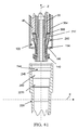
図41は、使い捨てピペットチップ220の例示的な実施形態の上方に配置される拡張式マンドレルコレット結合装置100の例示的な実施形態を示したもので、ピペットチップ220の中央長手方向Z軸に対して実質的に90度の角度を有する別例(代替例)の密閉座面(シール座面)2270を備えている。
FIG. 41 illustrates an exemplary embodiment of the expandable mandrel
図42は、別例(代替例)の密封座面2270を含む使い捨てピペットチップ内に位置する拡張式マンドレルコレット結合装置100の例示的な実施形態を示したもので、チップ220は最終着座状態までに持ち上げられ、および環状ウェッジ210がその最終位置まで移動しており、遠位のエラストマー要素140が最終的に圧縮され別例(代替例)の密封座面2270に対して密封されて着座した状態である最終的な結合状態が画定される。
FIG. 42 illustrates an exemplary embodiment of the expandable mandrel
図43は、別例(代替例)の密封座面2270に対する遠位のエラストマー要素140の最終的な圧縮状態を詳述したものである。
FIG. 43 details the final compressed state of the
図44は、円周状ないし環状で半径方向に凹状ないし凹んだ密封座面3270の形態の他の別例(代替例)の密封座面を含む、使い捨てピペットチップ220の上部内側を示したものである。図45は、図44に示された円周状ないし環状で半径方向に凹状ないし凹んだ密封座面3270を詳述したものである。
FIG. 44 shows the upper inside of
図46は、使い捨てピペットチップ220の例示的な実施形態を示し、円周状ないし環状で半径方向に凸状ないし突出した密封座面4270の形態の別の密封座面の詳細を示す。図47は、図46に示された円周状ないし環状で半径方向に凸状ないし突出した密封座面420を詳述したものである。
FIG. 46 shows an exemplary embodiment of a
図48は、使い捨てピペットチップ220の例示的な実施形態を示しており、円周状ないし環状で上向き歯端状の密封座面5270の形態である、さらに別の密封座面を示す。図49は、図48に示されている円周状ないし環状で上向き歯端の形態の密封座面を詳述する。
FIG. 48 shows an exemplary embodiment of a
図50は、例示したように、長手方向のZ軸に向かって開口し且つV形状の断面を有する使い捨てピペットチップ220の、V形状の円周内面(内周面)2244によって画定される別例(代替例)のV形状の溝2246を備えた使い捨てピペットチップ220の例示的な実施形態の上方に配置される、拡張式マンドレルコレット結合装置100の例示的な実施形態の部分的な縦断面の側面図である。
FIG. 50 illustrates, as illustrated, another example of a
図51は、別例(代替例)のV形状溝2246(図50)を備えた使い捨てピペットチップ220内に位置する拡張式マンドレルコレット結合装置100を示したものであり、チップ220が最終状態まで持ち上げられ、複数の拡張式マンドレルコレットセグメント200の丸い面202がV形状の溝2246内に延在し且つV形状の円周内面(内周面)に当接し、遠位のエラストマー要素140が最終的に圧縮されてチップの密封座面270に着座した状態にある。
FIG. 51 shows the expandable mandrel
図52は、複数の拡張式マンドレルコレットセグメント200のうちの1つの丸い面202が、V字形の溝2246内に延在し且つV字形の溝2246を画定するV字形の円周内面(内周面)2244に当接した状態を示す。
FIG. 52 shows a V-shaped circumferential inner surface (the inner circumference (the inner periphery of which the
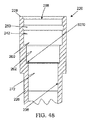
図53は、円周環状溝246を画定する円弧状の円周内面(内周面)244を有していない使い捨てピペットチップ1220の第2の例示的な実施形態の上方に配置される、拡張式マンドレルコレット結合装置の例示的な実施形態を示したものである。
FIG. 53 illustrates the expansion located above the second exemplary embodiment of the
図54は、第2の例示的な実施形態の使い捨てピペットチップ1220の内部を詳細に示したものであり、図18に示す第1の実質的に筒状の内面セクション242の中断された内面セクション242が中断(切れ目)のないものである点を除いて全ての部分において類似しており、これにより使い捨てピペットチップ1220の中断(切れ目)がない内面部分1242が画定され、内面セクション1242が第1の作用面を画定する。
FIG. 54 shows the interior of the
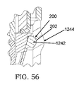
図55は、第2の例示的な実施形態の使い捨てピペットチップ1220内に位置する拡張式マンドレルコレット結合装置100の例示的な実施形態を示したものであり、結合装置100の停止ディスク肩面196が使い捨てピペットチップ1220の第2の例示的な実施形態の軸方向停止面260に当接し且つ複数の拡張式マンドレルコレットセグメント200の丸い面202が使い捨てピペットチップ1220の第2の例示的な実施形態の囲繞側壁の内面1242まで延びて当たり、これにより内面1242の変形1244が生じ、使い捨てピペットチップ1220の第2の例示的な実施形態の密封座面270に対して遠位のエラストマー要素140が最終的に圧縮され着座し密封した状態となる。
FIG. 55 illustrates an exemplary embodiment of the expandable mandrel
図56は、拡張式マンドレルコレット結合装置100の複数の拡張式マンドレルコレットセグメント200のうちの1つの丸い表面202が図55に示した使い捨てピペットチップの第2の例示的な実施形態の囲繞側壁の内面1242まで延びて当たり変形1244を生じさせた状態を詳述する。
56 is a surrounding sidewall of the second exemplary embodiment of the disposable pipette tip of which the
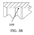
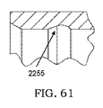
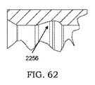
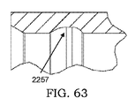
図57から図67は、少なくとも図19に示したセグメント200の円周状で環状のチップ溝、および少なくとも図50に示したV字状の溝のセグメント200に対する別例(代替例)の溝形状の実施形態を備えた、使い捨てピペットチップの例示的な実施形態の部分的な縦断面の側面図である。
57 to 67 show groove shapes of other examples (alternatives) to the circumferential annular chip groove of the
特に、図57から図67は、セグメント200を受容するための個々の別例(代替例)の溝形状2251から2261を示す。
In particular, FIGS. 57 to 67 show individual alternative (alternative)
別例(代替例)の例示的な実施形態のコレット2170
図68は、拡張式マンドレルコレット2170の第2または別例(代替)の例示的な実施形態を示しており、これは拡張式マンドレルコレット結合装置100(図5)の拡張式マンドレルコレット170(図5)に対する直接の代替物として構成されたものである。拡張式マンドレルコレット2170は、コレット170と機能は類似しているが、性能および寿命を改善する構成となっている。
68 shows a second or alternative (alternative) exemplary embodiment of the
図68および図69を参照して、膨張マンドレルコレット2170は、複数の周方向に離間した上方に延びるコレットアーム2180を備えており、これは下側の環状基部2172から半径方向外方に延びると共に上方に円弧状に移行し、自由な分割された 端2200で終端して下側の環状基部2172の軸方向上方に配置された分割カラーを画定する。複数の周方向に離間した上方に延びるコレットアーム2180は、複数の周方向に離間した上方に延びるカーフまたは溝2182の1つにより互いに分離される。
68 and 69, the
図68および図69を参照して、複数の上方に延びる複数のコレットアーム2180のそれぞれは、それぞれの上側アーム部2190内に移行するそれぞれの下側アーム部2186を備える。一つの実施形態では、複数の周方向に離間した下側アーム部2186は囲繞する(周囲を取り囲む)下側の本体部分2181を形成し、複数の周方向に離間した上側アーム部2190は下側の本体部2181から半径方向外方および上方向に移行する円錐台形状の囲繞する上側の本体部分2183を形成する。
68 and 69, each of the plurality of upwardly extending
図68および図69を参照して、遠位または下側の環状基部2172は、遠位または下側を向いた基部面2171を備える。遠位を向いた基部面2171は、下側の環状基部2172の遠位または下側の環状基部端2176で終端する短縮された遠位または下側の端部環状ステム面(端部環状脚面)2174内に下方に移行する。基部面2171および下側の端部環状ステム面2174は短縮された遠位側端の環状溝を画定する。
68 and 69, the distal or lower
図69に示すように、下側の環状基部2172は、内側の環状肩停止面2177内に上方に(上向きに)移行する内側円筒面2175をさらに備える。
As shown in FIG. 69, the lower
図69にさらに示したように、下側のアーム部2186は下側の環状基部2172に取付けられ、周方向に離間した下側の端部2184を備える。下側のアーム部2186はさらに、内側の環状で凹状の分割面または溝2191および外側の半径方向外方に延在する環状に分割された停止ディスク部2194を有する中間アーム部を画定する上側端部を備える。分割された停止ディスク2194は、複数の周方向に離間した上方に延びるコレットアーム2180の中間アーム部分の外側を囲み且つそこから半径方向に延び、環状の分割された停止ディスクを画定する。分割された停止ディスク2194の各々は、近位または上方を向いた停止ディスク面2198および遠位または下方を向いた停止ディスク面2196を備える。さらに、複数の下側のアーム部2186は、細長い中央本体部材102(図10)を囲むスペーサ160(図10)に密接に囲む内径を有する大きさ、内側筒状または内側分割面2188を備える。
As further shown in FIG. 69, the
図68および69を参照して、複数の周方向に離間した上側アーム部2190はそれぞれの下側アーム部2186から上方向および半径方向外方に移行すると共に、下側アーム部2186の上方でそこから半径方向外方に配置された複数の自由端2199内に終端し、複数の自由端2199は分割カラー2200を画定する半径方向外方に突出するセグメントを備え、各セグメントは外側の外向きの面2202を備え、これは一つの実施形態において外向きに丸いまたは円弧状のものである。
従って、上側アーム部2190は、分割された停止ディスク2194から、複数の半径方向外方に突出したセグメントまで、上方及び半径方向外方に移行し、分割カラー2200を画定する。また、複数の周方向に離間し半径方向外方および上方に延びる上側アーム部2190は、それぞれ内面2192を備えたセグメントを含んでおり、環状ウェッジ210(図13)の近位側に傾斜した環状側面216(図13)と相補的である、傾斜した分割された内面を形成する。
Referring to FIGS. 68 and 69, a plurality of circumferentially spaced
Thus, the
図12と図69を対比して、拡張式マンドレルコレット2170は、拡張式マンドレルコレット170に対して、各アーム2180のそれぞれの各端部2184の基部を広げ、およびアーム2180の端2184を半径方向に外方に広げて、アーム2180の各々の半径を拡張式マンドレルコレット170に対して増大させている。下端部を外側に押し出し、直径を大きくすることで、延びたアーム2180のそれぞれの底端2184におけるコードセグメントないし幅を大きくでき、延びたアーム2180のそれぞれの幅が増大することで、伸張したアーム2180のそれぞれの強度が高まる。さらに、アーム2180の下側端2184における半径方向の延長部が増大するので強度が増大する。結合機能は変わらない。
12 and 69,
エンジニアリング(工学技術)の観点から、伸長アーム2180は曲がった片持ちビームとしてモデル化できる。カプラが係合したり離脱する際に生じるような、ビームが曲げられたときの材料応力を評価するため、古典的な材料強度の技術が利用できる。さらに、曲げが繰り返しまたは周期的に行われるとき、適切な製品寿命を求めるために、材料応力が疲労強度に関して分析される。ビームの底部の幅を広げ、また関連する半径を増大することは、応力ないし圧力を軽減し、強度を向上させるために使用される形状変更である。
From an engineering point of view, the
装置の特徴 Equipment features
一つの観点において、本願のピペットチップ結合装置または拡張式マンドレルコレット結合装置100によれば、寿命が改善される。
In one aspect, the present pipette tip coupling device or the expandable mandrel
別の観点において、拡張式マンドレルコレット170の半径方向外方に突出したセグメント200はより堅固な結合を提供し、ピペットチップ220とカプラ100との間のより剛性の高い接合を提供する。
In another aspect, the radially outwardly projecting
別の観点において、拡張式マンドレルコレット170の半径方向外方に突出したセグメント200は、チップ220を引き上げ、これを効率的に着座させる。
In another aspect, the radially outwardly projecting
別の観点において、拡張式マンドレルコレット170の材料は、液体レベル検出や上記で詳述した他の用途のため、チップに電気回路を提供するために導電性材料から容易に作製できる。
In another aspect, the material of the
別の観点において、チップを自由空気(大気)中で排出ないし放出することによる影響(悪影響)をカプラ100は受けない。Oリングの結合寿命は、チップが自由空気中で排出されると悪影響を受ける。ばね付勢された排出スリーブによってチップが押し離される際にOリングがチップ内の溝によって擦られて摩耗するからである。半径方向外方に突出したセグメント200の硬さはこのような刻みや摩耗の有害な動作に耐えることができる。
In another aspect, the
別の観点において、拡張式マンドレルコレット170の材料は、上記で詳述した液体レベル検出や他の用途のために、チップに電気回路を提供するために、導電性材料から容易に作製できる。
In another aspect, the material of the
別の観点において、拡張式マンドレルコレット170の半径方向外方に突出したセグメント200は、寿命を改善するため、これに限定されないが、金属または硬質プラスチックなどの、硬質で耐久性のある材料から形成される。また、個別ないし個々の要素またはセグメントをプラスチック製のチップよりもずっと硬くすることで、Oリングのような軟質のエラストマー材料よりもより有効にチップの溝の中に入る。
In another aspect, the radially outwardly projecting
別の観点において、半径方向外方に突出したセグメント200は、機械的に効率的な設計であるため、小さい(低い)スクイズ/軸方向の力で作動させることができる。スクイズ/軸方向における必要な力が小さい程、軸方向の力を提供する関連部品の寿命が向上する。このようにスクイズ/軸方向における必要な力がより小さくてよい結果、エラストマー材料がそれ程圧縮されず、この半径方向外方に突出したセグメント200により、下側または遠位の密封部材140の寿命が改善される。
In another aspect, the radially outwardly projecting
別の観点によれば、この結合装置100では、交換が必要な場合に下側または遠位の密封部材140に容易にアクセスすることができる。また、下側または遠位の密封部材140は、LLD回路用に導電性である必要がなく、より多様な材料から作製できる。
According to another aspect, the
別の態様では、寿命が改善され且つ上記の下側または遠位の密封部材へのアクセスが容易であるので、メンテナンス費用がより低い。 In another aspect, maintenance costs are lower as the lifetime is improved and access to the lower or distal sealing member is facilitated.
さらに別の態様では着座が改善されるため、ピペット装置20に対するチップの位置合わせないし整列性が改善される。
In yet another aspect, improved seating may result in improved alignment of the tip with respect to the
方法の実施形態 Method embodiment
上記に照らして、そして別の観点において、ピペット装置によって支持ないし保持される拡張式マンドレルコレット結合装置の形態の少なくとも1つのピペットチップカプラへの、少なくとも1つのピペットチップの固定取り付けを行うための方法の例示的な実施形態が提供される。この方法は、以下の構成を備える。
(1) 分注(ピペッティング)される媒体内に浸漬するための開口した遠位端と、開口した遠位端と軸方向に反対側の開口した近位端との間に延び、通路開口を画定する内側囲繞面を有する側壁を備えたピペットチップを提供するステップ、
(2) ピペットチップカプラの囲繞面の軸方向に段付き(段状)のカプラ肩部によって形成された遠位を向いた軸方向停止肩面を含むピペットチップカプラを提供することであって、遠位を向いた軸方向停止肩面は、ピペットチップの側壁の内側囲繞面の軸方向に段付きの肩面によって形成された近位側を向いた軸方向停止面と相補的であるステップ、
(3) 前記ピペットチップカプラ本体の前記上側着座面上に、離間して且つ周方向に配置された(周方向に離間して配置された)複数の個別ないし個々の結合要素またはセグメントを提供するステップ、
(4) ピペットチップカプラによって支持ないし保持された遠位のエラストマー要素を軸方向に段付きのカプラ肩部の下側の位置に設けるステップ、
(5) ピペットチップの開口した近位端の上方において、ピペットチップカプラの遠位端を、ピペットチップカプラの中央長手軸とピペットチップの中央長手軸との間で軸方向に位置合わせ(整列)させて配置するステップ、
(6) ピペットチップカプラの遠位端をピペットチップの開口した近位端を通って並進させるステップであって、上記の並進を、遠位のエラストマー要素がピペットチップの側壁の内側囲繞面の軸方向に段付けされた肩部から遠位にあるピペットチップの側壁の内側囲繞面の円周状ないし環状で半径方向内方に傾斜し且つ遠位側に延びる内側作用面に接触するまで行うステップ、
(7) 複数の個別ないし個々の結合要素またはセグメントを、軸方向に円弧状の円周内面(内周面)の上側の軸方向に円弧状の周面セクタ部分と半径方向に延長ないし伸長して当接した状態になるように軸方向にスクイズ(押し込み)または押圧し、ピペットチップの軸方向停止面より上方の位置で、ピペットチップの側壁の内側囲繞面内に形成された溝を画定するステップであって、ピペットチップに近位側に向けられた半径方向および軸方向の合成的な予応力を提供し、遠位のエラストマー要素の外周部分がピペットチップの側壁の内側囲繞面の円周状ないし環状で半径方向内方に傾斜し且つ遠位側に延びる内側作用面に、軸方向および半径方向に密封当接するようになる圧縮状態に遠位側エラストマー要素を付勢し、ピペットチップの近位側を向いた軸方向停止面を前記ピペットチップカプラ本体の遠位側を向いた軸方向停止面に当接させて、ピペットチップ結合装置上でピペットチップの軸方向の結合位置を画定するステップ。
In light of the above, and in another aspect, a method for fixedly attaching at least one pipette tip to at least one pipette tip coupler in the form of an expandable mandrel collet coupling device supported or held by a pipetting device Exemplary embodiments of are provided. This method comprises the following configuration.
(1) an open distal end for immersion in the medium to be dispensed (pipetting) and an open proximal end axially opposite the open distal end, the passage opening being Providing a pipette tip with a side wall having an inner surrounding surface defining the
(2) A pipette tip coupler comprising a distally facing axial stop shoulder formed by an axially stepped shoulder of the enclosing surface of the pipette tip coupler, The distally facing axial stop shoulder surface being complementary to the proximally directed axial stop surface formed by the axially stepped shoulder surface of the inner surrounding surface of the side wall of the pipette tip;
(3) Providing a plurality of discrete and / or circumferentially-disposed (circumferentially spaced) coupling elements or segments on the upper seating surface of the pipette tip coupler body Step,
(4) providing a distal elastomeric element supported or held by the pipette tip coupler at a lower position of the axially stepped coupler shoulder;
(5) Above the open proximal end of the pipette tip, the distal end of the pipette tip coupler is axially aligned between the central longitudinal axis of the pipette tip coupler and the central longitudinal axis of the pipette tip Step to place and let
(6) translating the distal end of the pipette tip coupler through the open proximal end of the pipette tip, the above-mentioned translation being carried out by the distal elastomeric element being the axis of the inner surrounding surface of the side wall of the pipette tip Step from the directionally stepped shoulder to the circumferential to annular, radially inward sloping and distally extending inner working surface of the inner surrounding surface of the side wall of the pipette tip distal to the contact step ,
(7) A plurality of individual or individual coupling elements or segments are radially extended or extended with an arc-shaped circumferential surface sector portion on the upper side of the axially arc-shaped circumferential inner surface (inner circumferential surface) Axially squeeze or push to abut against, and define a groove formed in the inner surrounding surface of the side wall of the pipette tip at a position above the axial stop surface of the pipette tip Providing a radially and axially combined pre-stress directed proximally to the pipette tip, the outer circumferential portion of the distal elastomeric element being the circumference of the inner surrounding surface of the side wall of the pipette tip Biasing the distal elastomeric element into a compressed state in which it axially and radially sealingly abuts against a radially or inwardly, radially inwardly inclined and distally extending inner working surface, A proximally facing axial stop surface is abutted against the distally facing axial stop surface of the pipette tip coupler body to define an axial coupling position of the pipette tip on the pipette tip coupling device Step.
上述したような本発明の開示に照らして、上述した本発明の開示の実施形態の範囲および適正な趣旨から逸脱することなく、さらなる構造的な修正および改造が可能である。
例えば、図57から図67は、少なくとも図19に示される円周状で環状のチップ溝246、および少なくとも図50に示されたV形状溝セグメント200の、異なる代替えの例示的な実施形態を詳しく示した、部分的な縦断面の側面立面図である。特に、図57から図67は、セグメント200の受容のための、それぞれの代替えの溝形状(構造)2251から2261を示したものである。さらに、カプラのセグメントは、それぞれ異なる代替の例示的な実施形態である溝形状2251から2261とそれぞれ相補的な半径方向外向きの面を備えてもよい。したがって、第1の作用面は、これに限定されないが、図53から図56に示されたそれぞれの溝形状または中断(切れ目)のない構造の形態であり、第1の実質的に筒状の内面セクション242は中断(切れ目)がないものであり、これにより使い捨てピペットチップ1220の中断(途切れの内面セクション1242が画定される。さらに、チップの遠位のOリングの密封座面270は、これに限定されないが、平らな円錐形、凹状のアール(半径)、凸状のアール(半径)、段差付きなどの形態の異なる幾何学的形状ないし構造を有したものでも良い。さらに、遠位のOリングは、Oリングとは異なる形状を有してもよく、これに限定されないが、チップの遠位のOリングの密封座面270と相補的な形状でもよい。
In light of the present disclosure as described above, further structural modifications and alterations are possible without departing from the scope and proper spirit of the embodiments of the present disclosure described above.
For example, FIGS. 57-67 detail different alternative exemplary embodiments of the circumferential
産業上の利用可能性 Industrial applicability
上記のシステム、アセンブリ、装置、および使用および動作を含む方法の記載は、本発明の実施形態の産業上の利用可能性を例証したものである。 The above description of the system, assembly, apparatus, and method including use and operation, is illustrative of the industrial applicability of embodiments of the present invention.
したがって、上述した本開示の実施形態の範囲および正当な意味から逸脱することなく、かつ特許請求の範囲に記載されているように、さらに多くの構造的修正および改造が可能であることは明らかである。したがって、添付の特許請求の範囲の技術思想および範囲は、本発明の実施形態の上記の説明に限定されるものではない。また、添付の特許請求の範囲において、単数形の要素への言及は、明示的に記載されない限り、「1つのみ」を意味するものではなく、むしろ「1つ以上」を意味するものである。さらに、装置または方法が、本発明によって解決される各問題および全問題に対処する必要はなく、これら各請求項によって包含される。 Thus, it will be apparent that many further structural modifications and alterations are possible without departing from the scope and sensible meaning of the embodiments of the present disclosure described above and as set forth in the claims. is there. Accordingly, the spirit and scope of the appended claims should not be limited to the foregoing description of the embodiments of the present invention. Also, in the appended claims, reference to a singular element does not mean "only one," but rather means "one or more," unless explicitly stated otherwise . Furthermore, the device or method does not have to address each and every problem solved by the present invention and is covered by the respective claims.
Claims (116)
外面および内面を有する複数の周方向に離間したセグメントを有してなる分割カラーと、
前記分割カラーの下方に配置された環状基部と、
前記環状基部に取付けられた下側端と前記環状基部の上方に配置された上側自由端とを有する複数の上方に延びる周方向に離間したアームと、を有してなり、
前記上側自由端の各々は前記分割カラーの前記複数の周方向に離間したセグメントの異なる1つを支持し、
前記分割カラーの前記外面を前記分割カラーを囲むピペットチップの上側結合部の第1の内側作用面領域に結合するために、前記分割カラーが、前記分割カラーの前記内面に機械的な力が加えられると、第1の周径と前記第1の周径よりも大きな第2の周径との間で半径方向に拡張するように構成される、ピペットチップ結合装置。 A pipette tip coupling device for coupling and detaching a pipette tip to and from a pipetting device,
A split collar comprising a plurality of circumferentially spaced segments having an outer surface and an inner surface;
An annular base disposed below the split collar;
A plurality of upwardly extending circumferentially spaced arms having a lower end attached to the annular base and an upper free end disposed above the annular base,
Each of the upper free ends carries a different one of the plurality of circumferentially spaced segments of the split collar,
The split collar applies a mechanical force to the inner surface of the split collar in order to couple the outer surface of the split collar to a first inner working surface area of the upper joint of the pipette tip surrounding the split collar. A pipette tip coupling device, configured to radially expand between a first circumferential diameter and a second circumferential diameter greater than the first circumferential diameter.
請求項1に記載のピペットチップ結合装置。 The annular base portion comprising an annular disc member, the annular disc member transitioning to a downwardly reduced annular stem portion;
The pipette tip coupling device according to claim 1.
前記分割カラーが前記ピペットチップの前記上側結合部分の前記第1の内側作用面領域に対して半径方向に拡張される際に、前記エラストマー要素が前記ピペットチップの前記上側結合部分の前記第1の内側作用面領域の下の第2の内側作用面領域を押圧するように構成される、
請求項2に記載のピペットチップ結合装置。 It further comprises an elastomeric element surrounding the reduced diameter annular stem portion below the annular disc member,
When the split collar is radially expanded with respect to the first inner working surface area of the upper coupling portion of the pipette tip, the elastomeric element is adapted to the first of the upper coupling portion of the pipette tip. Configured to press a second inner working surface area below the inner working surface area,
The pipette tip coupling device according to claim 2.
請求項3に記載のピペットチップ結合装置。 Each of the plurality of upwardly extending circumferentially spaced arms has a plurality of radii forming a radially outwardly extending annular segmented stop disc disposed between the annular base member and the split collar. Having an outer intermediate surface with radially outwardly extending stop disc segments defining a direction outwardly extending stop disc segment,
The pipette tip coupling device according to claim 3.
請求項4に記載のピペットチップ結合装置。 When the split collar radially expands into engagement with the first inner working surface area and the elastomeric element is compressed against the second inner working surface area, the stop disc is movable. Configured to seat on an inner shoulder surface area of the pipette tip disposed between the first inner working surface area and the second inner working surface area of the pipette tip
The pipette tip coupling device according to claim 4.
前記中央本体は、上側端部と、上側肩端と下側基部端とを有する下側端部と、前記中央本体を通って延びる開口端通路を画定する内側側壁面とを有し、
前記中央本体は前記分割カラー、前記複数の上方に延び周方向に離間したアーム、および前記環状基部を通って延び、
前記環状基部は、前記中央本体の前記下側基部端の近位側上方で前記中央本体の前記下側端部の前記上側肩端に取り付けられる、
請求項5に記載のピペットチップ結合装置。 Further comprising a central body,
The central body has an upper end, a lower end having an upper shoulder end and a lower base end, and an inner sidewall surface defining an open end passage extending through the central body.
The central body extends through the split collar, the plurality of upwardly extending circumferentially spaced arms, and the annular base;
The annular base is attached to the upper shoulder end of the lower end of the central body, proximally above the lower base end of the central body.
The pipette tip coupling device according to claim 5.
前記環状ウェッジを通って延び、前記環状ウェッジを前記中央本体の前記上側端部の周りに軸方向に移動自在に取り付けるように構成された中央開口とをさらに有してなる、
請求項6に記載のピペットチップ結合装置。 An annular wedge having a top surface transitioning to a lower side having an outer peripheral inclined surface;
And a central opening extending through the annular wedge and configured to movably attach the annular wedge axially around the upper end of the central body.
The pipette tip coupling device according to claim 6.
請求項7に記載のピペットチップ結合装置。 The outer peripheral bevelled surface of the annular wedge is configured to abut the inner surface of the upper free end of the plurality of upwardly extending circumferentially spaced arms;
The pipette tip coupling device according to claim 7.
請求項8に記載のピペットチップ結合装置。 The annular wedge extends circumferentially around the outer peripheral sloping surface of the annular wedge in response to pressure applied to the top surface of the annular wedge member to couple the pipette tip to the pipetting device. The pipette tip is configured to be translated downward relative to the inner surface of the upper free end of the directionally spaced arms, and to release the pipette tip from the pipette device in response to a force released from the top surface of the annular wedge Configured to
The pipette tip coupling device according to claim 8.
中央本体であって、上側端部、下側基部端を有する下側端部、および前記中央本体を通って延びる開口端通路を画定する内側側壁面を備えた中央本体と、
前記中央本体の前記下側端部の領域を囲み前記下側基部端に隣接したエラストマー要素と、
前記中央本体の前記下側基部端の軸方向上方で前記中央本体の周囲に配置され且つ前記エラストマー要素の上方に配置された半径方向外方に延びる環状ディスク部を有してなる環状基部と、前記中央本体の周りで周方向に配置され且つ前記中央本体から半径方向に離間した複数の上方に延びる弾性アームとを有してなる、拡張式コレットと、を有してなり、
前記複数の上方に延びるアームは、前記環状基部の周りに取り付けられた下側端と、前記環状基部の上方の位置において前記中央本体を囲み且つ前記中央本体から半径方向に離間した分割カラーを画定する上側自由端とを有してなり、
前記分割カラーが内面と外面を有し、
前記エラストマー要素が前記ピペットチップの第2の内側作用面領域を押圧する際に、前記分割カラーをそれぞれピペットチップの第1の内側作用面領域に対して離脱状態から結合状態に移行するために、前記分割カラーが前記分割カラーの前記内面に加えられた機械的な力に応じて第1の周径と前記第1の周径より大きな第2の周径との間で半径方向に拡張するように構成される、
ピペットチップ結合装置。 A pipette tip coupling device for coupling and detaching a pipette tip to and from a pipetting device,
A central body having an upper end, a lower end having a lower proximal end, and an inner sidewall surface defining an open end passage extending through the central body;
An elastomeric element surrounding the area of the lower end of the central body and adjacent to the lower base end;
An annular base having a radially outwardly extending annular disc portion disposed axially above the lower base end of the central body and around the central body and disposed above the elastomeric element; An expandable collet comprising: a plurality of upwardly extending resilient arms circumferentially disposed about the central body and radially spaced from the central body;
The plurality of upwardly extending arms define a lower end attached about the annular base and a split collar radially surrounding the central body at a location above the annular base and spaced apart from the central body Have an upper free end that
The split collar has an inner surface and an outer surface,
In order to shift the split collar from the disengaged state to the coupled state respectively with respect to the first inner working surface area of the pipette tip when the elastomeric element presses the second inner working surface area of the pipette tip The split collar radially expanding between a first circumferential diameter and a second circumferential diameter greater than the first circumferential diameter in response to a mechanical force applied to the inner surface of the split collar Configured to
Pipette tip binding device.
請求項10に記載のピペットチップ結合装置。 Each of the plurality of upwardly extending resilient arms circumferentially spaced about the central body and radially spaced from the central body is disposed between the annular base member and the split collar Comprising a radially outwardly extending intermediate outer segment forming a plurality of circumferentially spaced segments defining an outwardly extending annular segmented stop disc;
The pipette tip coupling device according to claim 10.
請求項11に記載のピペットチップ結合装置。 Said split collar radially extending relative to said first inner working surface area of said pipette tip, and said elastomeric element being compressed at said second inner working surface area of said pipette tip; A stop disc is configured to seat on an inner shoulder active surface area of the pipette tip disposed between the first inner active surface area and the second inner active surface area of the pipette tip;
The pipette tip coupling device according to claim 11.
前記環状ウェッジの前記外側軸方向傾斜面が前記複数の上方に延びる弾性アームの前記上側自由端の前記内面に載るように構成される、
請求項12に記載のピペットチップ結合装置。 An annular wedge having a top surface transitioning to the lower side having an outer axially inclined surface, and extending through the annular wedge and axially pivoting the annular wedge around the upper end of the central body Further comprising an annular wedge having a central opening configured to be movably attached in a direction,
The outer axially inclined surface of the annular wedge being configured to rest on the inner surface of the upper free end of the plurality of upwardly extending resilient arms;
The pipette tip coupling device according to claim 12.
請求項13に記載のピペットチップ結合装置。 The central axial body of the annular wedge, with the annular wedge depending on the force applied to the top surface of the annular wedge member to couple the pipette tip to the pipetting device Are configured to be translated downward relative to the inner surface of the upper free end of the plurality of upwardly extending resilient arms circumferentially disposed about and circumferentially spaced from the central body Configured to withdraw the pipette tip from the pipette device in response to the
The pipette tip coupling device according to claim 13.
中央細長本体であって、上側端部と、下側本体端を有する下側端部と、前記中央細長本体を通って延びる開口端通路を画定する内側側壁面とを有し、前記中央細長本体が前記中央細長本体の前記下側本体端に近接して配置された下側の半径方向外方に延びる環状肩面を有してなる、前記中央細長本体と、
拡張可能なコレット部材であって、前記中央細長本体を囲み且つ縮径環状ステム部まで下方に移行し下側環状基部端で終端する半径方向外方に延びる環状ディスク部を備えた環状基部を有し、前記環状基部を前記中央細長本体の前記下側本体端の上方で前記中央細長本体の周りに集中化するために前記下側環状基部端が前記中央細長部材の前記下側の半径方向外方に延びる環状肩面に乗るように構成された、拡張可能なコレット部材と、
前記中央細長本体の周りで周方向に離間された複数の上方および半径方向外方に延びるアームであって、前記環状基部の上側環状部の周りに取り付けられた下側端、および傾斜内面と前記環状基部の上方に配置された分割カラーを画定する半径方向に突出した外面とを有する上側自由端を有してなり、および
前記上側内側傾斜面と前記中央細長本体との間に上側環状円錐台形隙間を形成するために、前記複数の上方および半径方向外方に延びるアームが、前記アームの中間部から延び且つ前記上側自由端の前記傾斜内面を含む上部内側傾斜面を有する、アームと、
前記半径方向外方に延びる環状ディスク部の下方で前記縮径環状ステム部を囲むエラストマー要素と、を有してなる、ピペットチップ結合装置。 A pipette tip coupling device for coupling and detaching a pipette tip to and from a pipetting device,
A central elongated body having an upper end, a lower end having a lower body end, and an inner sidewall surface defining an open end passage extending through the central elongated body, the central elongated body Said central elongated body having a lower radially outwardly extending annular shoulder surface disposed proximate to said lower body end of said central elongated body;
An expandable collet member having an annular base with a radially outwardly extending annular disc encircling the central elongated body and transitioning downward to a reduced diameter annular stem and terminating at a lower annular base end. Said lower annular base end radially outwardly of said lower central elongate member to center said annular base above said lower main body end of said central elongate body and around said central elongate body. An expandable collet member configured to ride on an outwardly extending annular shoulder;
A plurality of upwardly and radially outwardly extending arms circumferentially spaced about the central elongated body, the lower end attached about the upper annulus of the annular base, and an inclined inner surface and An upper free end having a radially projecting outer surface defining a split collar disposed above the annular base, and an upper annular frusto-conical shape between the upper inner inclined surface and the central elongated body The plurality of upwardly and radially outwardly extending arms having an upper inner beveled surface extending from the middle portion of the arms and including the beveled inner surface of the upper free end to form a gap;
An elastomeric element surrounding the reduced diameter annular stem below the radially outwardly extending annular disc.
請求項15に記載のピペットチップ結合装置。 The middle portions of the plurality of upwardly and radially outwardly extending arms together form a radially outwardly extending annular segmented stop disk disposed between the split collar and the annular base. Having an outer surface with radially outwardly extending stop disc segments configured to
The pipette tip coupling device according to claim 15.
前記環状ウェッジの前記外側軸方向傾斜面が、前記複数の上方および半径方向外方に延びるアームの前記上側自由端の前記傾斜内面に載るように構成される、
請求項16に記載のピペットチップ結合装置。 An annular wedge having a top surface transitioning to the lower side having an outer axially sloping surface, and extending through the annular wedge and axially pivoting the annular wedge around the upper end of the central body Further comprising an annular wedge having a central opening configured to movably attach in the direction,
The outer axially sloping surface of the annular wedge being configured to rest on the sloped inner surface of the upper free end of the plurality of upwardly and radially outwardly extending arms;
The pipette tip coupling device according to claim 16.
請求項17記載のピペットチップ結合装置。 The radially projecting outer surface of the upper free end is engaged to a first inner working surface area in an upper coupling portion of a pipette tip that surrounds the pipette tip coupling device, and the lower elastomeric element is coupled to the upper portion. The annular split stop disk which is compressed in the second inner working surface area of the joint and which extends radially outwardly of the first inner working surface area and the second inner working surface area. Between the annular wedge and the outer axial direction of the annular wedge in response to the force applied to the top surface of the annular wedge to seat against the inner shoulder active surface area within the upper joint of the pipette tip. Configured to translate an inclined surface downward relative to the inclined inner surface of the upper free end,
The pipette tip coupling device according to claim 17.
前記頂面部分に選択的に接触し前記環状ウェッジを下方に並進するための力を加えながら前記ピペットチップと前記プロセッサとを電気的に接触させるために、前記軸力並進手段の前記第1の端が前記環状ウェッジの前記頂面部分の上方の位置に配置される、
請求項18記載のピペットチップ結合装置。 The split collar, the wedge member, and the pipette tip are each selectively connected to a first end of a liquid level conductive lead made of conductive material and supported at a first end of an axial translation means. The liquid level conductive lead further comprising a second end electrically connected to the processor, and a force for selectively contacting the top surface portion to translate the annular wedge downwardly. The first end of the axial force translating means is disposed at a position above the top surface portion of the annular wedge, for additionally bringing the pipette tip and the processor into electrical contact,
The pipette tip coupling device according to claim 18.
前記ピペットチップの前記側壁の前記近位結合端により囲まれた結合装置と、を有してなるピペットチップアセンブリであって、
前記結合装置が、
中央本体であって、上側端部、下側本体端を有する下側端部、および前記中央本体を通って延び前記ピペットチップの前記通路開口と開放連通した開口端通路を画定する内側側壁面を有してなる中央本体、
前記下側本体端に隣接し前記中央本体の前記下側端部の領域を囲むエラストマー要素、
環状基部であって、前記環状基部を通って延在する開口を有し、前記中央本体の前記下側本体端の軸方向上方で前記中央本体の周りに配置された環状基部、および
前記中央本体の周りに周方向に離間し且つ前記中央本体から半径方向に離間した複数の上方に延びる弾性アームであって、前記環状基部部材の周りに取り付けられた下側端と、前記環状基部の上方の位置において前記中央本体を囲み且つ前記中央本体から半径方向に離間した分割カラーを画定する上側自由端とを有し、前記分割カラーが内面と外面を有する、複数の上方に延びる弾性アーム、を有してなり、
前記分割カラーと前記環状基部との間に配置された半径方向外方に延びる環状分割停止ディスクを画定するために、前記複数の上方に延びる弾性アームのそれぞれが、前記複数の上方に延びる弾性アームのそれぞれの中間外側面から半径方向外方に延びる停止ディスクセグメントを有し、
前記分割カラーを解放状態から前記ピペットチップの前記側壁の前記近位結合端の前記内面の第1の内側作用面領域に結合した状態まで移行し、同時に前記エラストマー要素を前記上側結合部の第2の内側作用面領域に対して圧縮し、また前記半径方向外方に延びる環状分割停止ディスクを前記ピペットチップの前記上側結合部分内において前記第1の内側作用面領域と前記第2の内側作用面領域との間で前記上側結合部分内の内側肩部作用面領域に着座させるために、前記分割カラーは第1の外周と前記第1の外周よりも大きな第2の外周との間で前記分割カラーの前記内面に加えられた機械的圧力に応じて半径方向に拡張するように構成される、ピペットチップアセンブリ。 A pipette tip having a side wall, the side wall having an inner surface defining a passage opening surrounded by the side wall, the distal end of the side wall being immersed in the medium in which the passage opening is pipetted And a pipette tip extending along a central longitudinal axis of the pipette tip between a proximal coupled end of the side wall and the axially opposite side;
A coupling device surrounded by the proximal coupling end of the side wall of the pipette tip;
The coupling device is
A central body having an upper end, a lower end having a lower body end, and an inner sidewall surface extending through the central body and defining an open end passage in open communication with the passage opening of the pipette tip Central body, having
An elastomeric element adjacent to the lower body end and surrounding an area of the lower end of the central body,
An annular base having an opening extending through the annular base, the annular base being disposed about the central body axially above the lower body end of the central body, and the central body A plurality of upwardly extending resilient arms circumferentially spaced about and circumferentially spaced from said central body, said lower ends mounted about said annular base member; A plurality of upwardly extending resilient arms having an upper free end surrounding the central body in position and defining a split collar radially spaced from the central body, the split collar having an inner surface and an outer surface It becomes
Each of the plurality of upwardly extending resilient arms defines a plurality of upwardly extending resilient arms to define a radially outwardly extending annular split stop disc disposed between the split collar and the annular base. A stop disk segment extending radially outward from the respective medial outer surface of the
The split collar is transferred from the released state to a state where it is coupled to the first inner working surface area of the inner surface of the proximal coupling end of the side wall of the pipette tip, while at the same time the elastomeric element is coupled to the second of the upper coupling portion A radially inward extending annular split stop disk for said inner working surface area of said pipet tip and said first inner working surface area and said second inner working surface within said upper coupling portion of said pipette tip In order to be seated on the inner shoulder working surface area in the upper coupling part between the area, the dividing collar is divided between the first outer circumference and a second outer circumference which is larger than the first outer circumference. A pipette tip assembly configured to radially expand in response to mechanical pressure applied to the inner surface of a collar.
前記外側軸方向傾斜面が、前記上側自由端の前記内面に載るように構成される、
請求項20記載のピペットチップアセンブリ。 An annular wedge having a top surface transitioning to the lower side with an outer axially inclined surface, and extending through it (the annular wedge) and the annular shape around the upper end of the central body Further comprising an annular wedge having a central opening configured to movably mount the wedge axially;
The outer axially inclined surface is configured to rest on the inner surface of the upper free end;
21. The pipette tip assembly of claim 20.
請求項21記載のピペットアセンブリ。 The annular wedge includes the apex of the annular wedge for engaging the outer surface of the upper free end with the first inner working surface area of the inner surface of the proximal coupling end of the side wall of the pipette tip. Configured to translate the outer axially inclined surface downwardly relative to the inclined inner surface of the upper free end in response to a force applied to the surface portion;
22. The pipette assembly of claim 21.
請求項22に記載のピペットアセンブリ。 The split collar, the annular wedge, and the pipette tip are made of a conductive material to selectively contact a first lead end of a fluid level conductive lead having a second lead end electrically connected to the processor The first to provide electrical contact between the pipette tip and the processor while selectively contacting the top surface and applying a force to translate the annular wedge downwards; The lead end of the shaft is adapted to be supported at the first end of the axial translation means, the first end of the axial translation means being disposed at a position above the top surface of the annular wedge,
23. The pipette assembly of claim 22.
請求項23に記載のピペットアセンブリ。 Further comprising a pipetting device mounting flange operably coupled to the upper end of the central body of the coupling device;
24. The pipette assembly of claim 23.
遠位端で終端する中央本体であって、前記中央本体を通って延びる開口端通路を画定する内側囲繞側壁面を備えた中央本体、
前記中央本体を囲み前記中央本体の前記遠位端に隣接したエラストマー要素、および
前記細長中央本体を囲む拡張コレットであって、少なくともその一部が前記エラストマー要素の近位にある環状基部と、前記環状基部に取り付けられた遠位端と近位自由アーム部とを備えた複数の周方向に離間したアームセグメントを有する分割カラーとを備え、各アームセグメントが外側面と内側面とを有する拡張コレットを有してなる、ピペットチップ結合装置。 A pipette tip coupling device for coupling and detaching a pipette tip to and from a pipetting device,
A central body terminating at a distal end, the central body having an inner surrounding sidewall surface defining an open end passage extending therethrough;
An elastomeric element surrounding the central body and adjacent the distal end of the central body, and an expanding collet surrounding the elongated central body, at least a portion of which is proximal to the elastomeric element; An extended collet comprising: a split collar having a plurality of circumferentially spaced arm segments with a distal end and a proximal free arm attached to an annular base, each arm segment having an outer surface and an inner surface A pipette tip binding device.
前記環状ウェッジが、近位ウェッジ面と、遠位ウェッジ面であって前記近位ウェッジ面の外周が前記遠位ウェッジ面の外周よりも大きい遠位ウェッジ面と、前記近位ウェッジを前記遠位ウェッジに連結する外面と、を有してなり、
前記環状ウェッジの前記外面が、前記複数の周方向に離間したアームセグメントの前記近位自由アーム部のそれぞれの前記内面に当接する、
請求項25に記載のピペットチップ結合装置。 Further comprising an annular wedge movably surrounding the central body,
The annular wedge includes a proximal wedge surface, a distal wedge surface, the distal wedge surface having an outer periphery larger than the outer periphery of the distal wedge surface, and the proximal wedge distally And an outer surface connected to the wedge,
The outer surface of the annular wedge abuts the inner surface of each of the proximal free arms of the plurality of circumferentially spaced arm segments.
The pipette tip coupling device according to claim 25.
請求項25に記載のピペットチップ結合装置。 The split collar may extend radially between a first perimeter and a second perimeter larger than the first perimeter.
The pipette tip coupling device according to claim 25.
前記半径方向外方に延びる停止ディスクセグメントが分割された停止ディスクを形成する、
請求項25に記載のピペットチップ結合装置。 Each of the plurality of outer surfaces of the circumferentially spaced arm segments further includes a radially outwardly extending stop disk segment, and the radially outwardly extending stop disk segments form a segmented stop disk. ,
The pipette tip coupling device according to claim 25.
請求項26に記載のピペットチップ結合装置。 The split collar and the annular wedge are made of conductive material,
The pipette tip coupling device according to claim 26.
遠位端で終端する中央本体であって、前記中央本体を通って延びる開口端通路を画定する内側囲繞側壁面を備えた中央本体、
前記中央本体を囲み前記中央本体の前記遠位端に隣接したエラストマー要素、および
前記中央本体を囲む拡張コレットを有してなり、
前記拡張コレットが、少なくとも一部が前記エラストマー要素の近位にある環状基部であって近位環状ディスクと遠位縮径環状ステムを有してなる環状基部と、複数の周方向に離間したアームセグメントとを有する分割カラーとを有してなり、
前記周方向に離間したアームセグメントのそれぞれが、外面、内面、近位自由アーム部、および遠位アーム端を有してなり、
前記遠位アーム端が前記近位環状ディスクに取り付けられており、および前記近位自由アーム部が前記環状基部の上方に延びている、
ピペットチップ結合装置。 A pipette tip coupling device for coupling and detaching a pipette tip to and from a pipetting device,
A central body terminating at a distal end, the central body having an inner surrounding sidewall surface defining an open end passage extending therethrough;
An elastomeric element surrounding the central body and adjacent the distal end of the central body, and an expanding collet surrounding the central body,
A plurality of circumferentially spaced arms, wherein the expanding collet is an annular base at least partially proximal to the elastomeric element, the annular base comprising a proximal annular disc and a distal reduced diameter annular stem; And a segmented color having segments, and
Each of the circumferentially spaced arm segments has an outer surface, an inner surface, a proximal free arm portion, and a distal arm end,
The distal arm end is attached to the proximal annular disc, and the proximal free arm extends above the annular base
Pipette tip binding device.
請求項30に記載のピペットチップ結合装置。 Said elastomeric element comprises an O-ring,
The pipette tip coupling device according to claim 30.
前記スペーサが前記中央本体を囲む筒状本体を有してなる、
請求項30に記載のピペットチップ結合装置。 Further comprising a spacer,
The spacer has a cylindrical body surrounding the central body;
The pipette tip coupling device according to claim 30.
前記環状ウェッジが、近位ウェッジ面と、遠位ウェッジ面であって前記近位ウェッジ面の外周が前記遠位ウェッジ面の外周よりも大きい遠位ウェッジ面と、前記近位ウェッジ面を前記遠位ウェッジ面に連結する外面とを有してなり、
前記環状ウェッジの前記外面が、前記複数の周方向に離間したアームセグメントの前記近位自由アーム部のそれぞれの前記内面に当接する、
請求項30に記載のピペットチップ結合装置。 Further comprising an annular wedge movably surrounding the central body,
The annular wedge includes a proximal wedge surface, a distal wedge surface where the outer periphery of the proximal wedge surface is larger than the outer periphery of the distal wedge surface, and the proximal wedge surface And an outer surface connected to the wedge surface,
The outer surface of the annular wedge abuts the inner surface of each of the proximal free arms of the plurality of circumferentially spaced arm segments.
The pipette tip coupling device according to claim 30.
請求項30に記載のピペットチップ結合装置。 The split collar may extend radially between a first perimeter and a second perimeter larger than the first perimeter.
The pipette tip coupling device according to claim 30.
前記半径方向外方に延びる停止ディスクセグメントが分割された停止ディスクを形成する、
請求項30に記載のピペットチップ結合装置。 Each of the plurality of outer surfaces of the circumferentially spaced arm segments further comprising a radially outwardly extending stop disc segment;
The radially outwardly extending stop disk segments form a split stop disk,
The pipette tip coupling device according to claim 30.
請求項33に記載のピペットチップ結合装置。 The split collar and the annular wedge are made of a conductive material,
34. The pipette tip coupling device according to claim 33.
近位端面を含む近位シャンクと、遠位ステム部と、前記遠位ステム部より遠位の端板であって前記遠位ステム部の直径よりも大きな直径を有する端板と、前記近位端面から前記遠位端板を通って長手方向に延びる開口通路を形成する開口端内側囲繞面と、を有する中央本体、
前記遠位ステム部の周りに配置され、前記遠位端板に隣接する遠位エラストマー要素、および、
前記中央本体の周りに配置された拡張コレットであって、
近位ディスク部および遠位コレットステム端部を有する環状基部と、
複数の周方向に離間した弾性的な上方に延びるアームであって、各周方向に離間した弾性的な上方に延びるアームが、前記ディスク部に取り付けられた遠位端、近位自由アーム部、および半径方向外方に延びる停止ディスクセグメントを含む外面とを有する複数の周方向に離間した弾性的な上方に延びるアームと、を有する拡張コレットを有してなり、
前記複数の周方向に離間した弾性的な上方に延びるアームの前記近位自由アーム部が、第1の外周である非拡張状態と、前記第1の外周よりも大きな第2の外周である拡張状態との間で、前記中央本体に対して半径方向に拡張することができる、
ピペットチップ結合装置。 A pipette tip coupling device for coupling and detaching a pipette tip to and from a pipetting device,
A proximal shank including a proximal end face, a distal stem portion, an end plate distal to the distal stem portion and having a diameter greater than a diameter of the distal stem portion; A central body having an open end inner surrounding surface defining an open passage extending longitudinally from an end face through the distal end plate;
A distal elastomeric element disposed about the distal stem and adjacent the distal end plate;
An expanding collet disposed about the central body,
An annular base having a proximal disc portion and a distal collet stem end;
A plurality of circumferentially spaced resilient upwardly extending arms, each circumferentially spaced resilient upwardly extending arm attached to the disc portion at a distal end, a proximal free arm portion, And a plurality of circumferentially spaced resilient upwardly extending arms having a radially outwardly extending stop disc segment and an outer surface including a radially extending outwardly extending collet.
The proximal free arm portion of the plurality of circumferentially spaced resilient upwardly extending arms has a first outer periphery in an unexpanded state and an outer peripheral portion having a second outer periphery larger than the first outer periphery. Radially expandable with respect to the central body, between states
Pipette tip binding device.
請求項37に記載のピペットチップ結合装置。 Said elastomeric element comprises an O-ring,
The pipette tip coupling device according to claim 37.
前記コレットを前記長手中央軸に沿って前記中央本体と同軸状に取り付けるために前記遠位コレットステム端部が前記近位ステム停止肩面に当接する、
請求項37に記載のピペットチップ結合装置。 The distal stem portion comprises a proximal stem stop shoulder having a diameter greater than the diameter of the proximal shank, and coaxially attaching the collet to the central body along the longitudinal central axis The distal collet stem end abuts against the proximal stem stop shoulder surface for
The pipette tip coupling device according to claim 37.
請求項37に記載のピペットチップ結合装置。 The perimeter of the distal elastomeric element is larger than the perimeter of the end plate of the central body
The pipette tip coupling device according to claim 37.
前記拡張コレットが、前記遠位エラストマー要素の前記近位面と前記内面に当接する、
請求項37に記載のピペットチップ結合装置。 The distal elastomeric element has a proximal surface and an inner surface, and the expanding collet abuts the proximal surface and the inner surface of the distal elastomeric element.
The pipette tip coupling device according to claim 37.
前記環状ウェッジが、近位ウェッジ面と、遠位ウェッジ面であって前記近位ウェッジ面の外周が前記遠位ウェッジ面の外周よりも大きい遠位ウェッジ面と、前記近位ウェッジ面を前記遠位ウェッジ面に連結する外面と、を有してなり、
前記環状ウェッジの前記外面が前記複数の周方向に離間したアームセグメントの前記近位自由アーム部のそれぞれの前記内面に当接する、
請求項37に記載のピペットチップ結合装置。 Further comprising an annular wedge movably surrounding the central body,
The annular wedge includes a proximal wedge surface, a distal wedge surface where the outer periphery of the proximal wedge surface is larger than the outer periphery of the distal wedge surface, and the proximal wedge surface And an outer surface coupled to the lateral wedge surface,
The outer surface of the annular wedge abuts the inner surface of each of the proximal free arms of the plurality of circumferentially spaced arm segments;
The pipette tip coupling device according to claim 37.
請求項37に記載のピペットチップ結合装置。 Further comprising a substantially cylindrical spacer surrounding said central body,
The pipette tip coupling device according to claim 37.
請求項42に記載のピペットチップ結合装置。 The expanding collet and the annular wedge are made of conductive material,
43. The pipette tip coupling device according to claim 42.
開口近位端と開口遠位端との間でピペットチップの中央長手軸に沿って延びる開口内側通路を備えた囲繞側壁、
前記囲繞側壁の内面に形成され前記開口近位端より遠位の第1セクションであって、
第1の直径を有し実質的に筒状の上側第1部分と、
前記第1の直径を有し実質的に筒状の下側第1部分と、
前記実質的に筒状の上側第1部分と前記実質的に筒状の下側第1部分との間に置かれた環状溝と、を有する第1セクション、
実質的に筒状の面を有し前記囲繞側壁の前記内面に形成され前記第1セクションより遠位の第2セクションであって、前記第1の直径より小さい第2の直径を有する第2セクション、
前記第1セクションと前記第2セクションとの接合部で前記囲繞側壁の前記内面に形成された停止肩面、
実質的に筒状の面を有し前記囲繞側壁の前記内面に形成され前記第2セクションより遠位の第3セクションであって、前記第2の直径よりより小さい第3の直径を有する第3セクション
前記第2セクションと前記第3セクションとの接合部で前記囲繞側壁の前記内面に形成された密封座面、および
前記第3セクションと前記遠位開口下側端との間で前記囲繞側壁の前記内面に形成された少なくとも1つの円錐台形セクションを有してなる、ピペットチップ。 A pipette tip,
A surrounding sidewall with an open inner passage extending along the central longitudinal axis of the pipette tip between the open proximal end and the open distal end;
A first section formed on the inner surface of the surrounding sidewall and distal to the open proximal end,
A substantially cylindrical upper first portion having a first diameter;
A substantially cylindrical lower first portion having the first diameter;
A first section having an annular groove disposed between the substantially cylindrical upper first portion and the substantially cylindrical lower first portion;
A second section having a substantially cylindrical surface formed on the inner surface of the enclosing sidewall and distal to the first section, the second section having a second diameter smaller than the first diameter. ,
A stop shoulder formed on the inner surface of the surrounding sidewall at the junction of the first section and the second section;
A third section having a substantially cylindrical surface and formed on the inner surface of the surrounding sidewall and distal to the second section, the third section having a third diameter smaller than the second diameter. Section A sealing bearing surface formed on the inner surface of the surrounding sidewall at the junction of the second section and the third section, and of the surrounding sidewall between the third section and the distal opening lower end A pipette tip comprising at least one frusto-conical section formed on the inner surface.
請求項45に記載のピペットチップ。 Said stop shoulder surface being annular and substantially flat substantially perpendicular to said central longitudinal axis of the pipette tip;
46. The pipette tip of claim 45.
請求項45に記載のピペットチップ。 Said sealing bearing surface being annular and substantially flat substantially perpendicular to said central longitudinal axis of the pipette tip;
46. The pipette tip of claim 45.
前記第2セクションと前記密封座面との交点に上側環状密封座面端と、
前記密封座面と前記第3セクションとの接合部に下側環状密封座面端とをさらに有してなり、
前記上側環状密封座面端が前記下側環状密封座面端よりも直径が大きい、
請求項45に記載のピペットチップ。 The sealing seat is a frusto-conical annular surface;
An upper annular seal bearing end at the intersection of the second section and the seal bearing surface;
And a lower annular seal seat end at the junction of the seal seat and the third section,
The upper annular seal bearing end is larger in diameter than the lower annular seal bearing end,
46. The pipette tip of claim 45.
請求項45に記載のピペットチップ。 Said annular groove is concave,
46. The pipette tip of claim 45.
請求項45に記載のピペットチップ。 The method further comprises an annular chamfered inner surface formed on the inner surface of the surrounding sidewall, extending radially inward from the open proximal end and terminating at the proximal end of the first section.
46. The pipette tip of claim 45.
前記囲繞側壁の内面に形成され、前記第3セクションより遠位の、第4セクションと、
前記囲繞側面の内面に形成され、前記第4セクションより遠位で、前記遠位開口端の近位の、第5セクションとをさらに有してなり、
前記第5セクションが前記第4セクションより大きなテーパを有する、
請求項45に記載のピペットチップ。 A fourth section, wherein the at least one frusto-conical section is formed on the inner surface of the surrounding sidewall and distal to the third section;
Further comprising a fifth section formed on an inner surface of the surrounding side, distal to the fourth section, and proximal to the distal open end,
The fifth section has a greater taper than the fourth section,
46. The pipette tip of claim 45.
前記停止肩面が環状で、ピペットチップの前記中央長手軸に実質的に垂直な実質的に平らな面であり、
前記密封座面が、環状で、ピペットチップの前記中央長手軸に実質的に垂直な実質的に平らな面であり、
前記環状溝が凹状であり、および
前記少なくとも1つの円錐台形セクションが、前記囲繞側壁の前記内面に形成され前記第3セクションより遠位の第4セクションと、前記囲繞側壁の前記内面に形成され前記第4セクションより遠位で前記遠位開口端の近位にある第5セクションであって前記第4セクションより大きなテーパを有する第5セクションと、を有してなる、
請求項45記載のピペットチップ。 Further comprising an annular chamfered inner surface formed on the inner surface of the surrounding sidewall, extending radially inward from the open proximal end and terminating at the proximal end of the first section;
The stop shoulder is annular and is substantially flat substantially perpendicular to the central longitudinal axis of the pipette tip;
Said sealing bearing surface being annular and substantially flat substantially perpendicular to said central longitudinal axis of the pipette tip;
The annular groove is concave, and the at least one frusto-conical section is formed in the inner surface of the surrounding sidewall and is formed in the fourth surface distal to the third section and in the inner surface of the surrounding sidewall. And a fifth section distal to the fourth section and proximal to the distal open end, the fifth section having a larger taper than the fourth section.
46. The pipette tip of claim 45.
前記停止肩面が環状で、ピペットチップの前記中央長手軸に実質的に垂直な実質的に平らな面であり、
前記密封座面が、円錐台形の環状面であり、前記第2セクションと前記密封座面との交点に上側環状密封座面端と、前記密封座面と前記第3セクションとの接合部に下側環状密封座面端とを有してなり、
前記上側環状密封座面端が前記下側環状密封座面端よりも直径が大きく、
前記環状溝が凹状であり、および
前記少なくとも1つの円錐台形セクションが、前記囲繞側壁の前記内面に形成され前記第3セクションより遠位の第4セクションと、前記囲繞側面の前記内面に形成され前記第4セクションより遠位で前記遠位開口端の近位の第5セクションとをさらに有してなり、
前記第5セクションが前記第4セクションより大きなテーパを有する、
請求項45記載のピペットチップ。 Further comprising an annular chamfered inner surface formed on the inner surface of the surrounding sidewall, extending radially inward from the open proximal end and terminating at the proximal end of the first section;
The stop shoulder is annular and is substantially flat substantially perpendicular to the central longitudinal axis of the pipette tip;
The sealing bearing surface is a frusto-conical annular surface, and at the intersection of the second section and the sealing bearing surface is an upper annular sealing bearing surface end, and a junction of the sealing bearing surface and the third section. And a side annular sealing bearing end,
Said upper annular seal bearing end having a larger diameter than said lower annular seal bearing end;
The annular groove is concave, and the at least one frusto-conical section is formed in the inner surface of the surrounding sidewall and is formed in a fourth section distal to the third section and in the inner surface of the surrounding surface. Further comprising a fifth section distal to the fourth section and proximal to the distal open end;
The fifth section has a greater taper than the fourth section,
46. The pipette tip of claim 45.
請求項45に記載のピペットチップ。 The surrounding side wall is made of a conductive material,
46. The pipette tip of claim 45.
請求項52に記載のピペットチップ。 The surrounding side wall is made of a conductive material,
53. The pipette tip of claim 52.
請求項53に記載のピペットチップ。 The surrounding side wall is made of a conductive material,
54. The pipette tip of claim 53.
前記ピペットチップが、開口近位端と開口遠位端との間で前記ピペットチップの中央長手軸に沿って延びる開口内側通路を備えた囲繞側壁を有してなり、
前記ピペットチップ結合装置が、遠位端で終端する中央本体であって前記中央本体を通って延びる開口端通路を画定する内側囲繞側壁面を有する中央本体と、前記中央本体を囲み前記中央本体の前記遠位端に隣接するエラストマー要素と、前記細長い中央本体を囲む拡張コレットであって少なくとも一部が前記エラストマー要素の近位にある環状基部および前記環状基部に取り付けられた遠位端と近位自由アーム部分とを備えた複数の周方向に離間したアームセグメントを備え前記アームセグメントがそれぞれ外面と内面を備えた分割カラーを有する拡張コレットと、を有してなり、
前記ピペットチップを前記ピペットチップ結合装置に固定するために、前記複数の周方向に離間したアームセグメントの前記近位自由アーム部のそれぞれの上側部分が前記ピペットチップの前記囲繞側壁の第1の内面に当接し、および
前記エラストマー要素が前記ピペットチップの前記囲繞側壁の第2の内面に当接して前記ピペットチップ結合装置と前記ピペットチップの間に密封が形成される、ピペットチップ結合装置とピペットチップのアセンブリ。 An assembly of a pipette tip connector and a pipette tip,
The pipette tip having a surrounding sidewall with an open inner passage extending along the central longitudinal axis of the pipette tip between the open proximal end and the open distal end;
A central body having an inner surrounding sidewall surface defining a central body terminating at the distal end and defining an open end passage extending therethrough, the pipette tip coupling device surrounding the central body and of the central body An elastomeric element adjacent the distal end, an expanding collet surrounding the elongated central body, an annular base at least a portion of which is proximal to the elastomeric element and a distal end and proximal end attached to the annular base A plurality of circumferentially spaced arm segments with free arm portions, said arm segments each having an extended collet with a split collar with an outer surface and an inner surface,
An upper portion of each of the proximal free arms of the plurality of circumferentially spaced arm segments for securing the pipette tip to the pipette tip coupling device is a first inner surface of the surrounding sidewall of the pipette tip. A pipette tip coupling device and a pipette tip, wherein the elastomeric element abuts against the second inner surface of the surrounding sidewall of the pipette tip so that a seal is formed between the pipette tip coupling device and the pipette tip Assembly.
前記環状ウェッジが、近位ウェッジ面と、遠位ウェッジ面であって前記近位ウェッジ面の外周が前記遠位ウェッジ面の外周よりも大きい遠位ウェッジ面と、前記外面が前記近位ウェッジを前記遠位ウェッジに連結する外面と、を有してなり、
前記環状ウェッジの前記外面が、前記複数の周方向に離間したアームセグメントの前記近位自由アーム部分それぞれの前記内面に当接する、
請求項57に記載のピペットチップ結合装置とピペットチップのアセンブリ。 Further comprising an annular wedge movably surrounding the central body,
The annular wedge includes a proximal wedge surface, a distal wedge surface where the outer periphery of the proximal wedge surface is larger than the outer periphery of the distal wedge surface, and the outer surface is the proximal wedge. And an outer surface coupled to the distal wedge.
The outer surface of the annular wedge abuts the inner surface of each of the proximal free arm portions of the plurality of circumferentially spaced arm segments.
An assembly of a pipette tip connector and a pipette tip according to claim 57.
請求項58に記載のピペットチップ結合装置とピペットチップのアセンブリ。 The split collar, the annular wedge, and the pipette tip are made of a conductive material,
59. The pipette tip coupling device and pipette tip assembly of claim 58.
実質的に筒状の面を有し前記囲繞側壁の前記内面に形成され前記開口近位端より遠位の第1セクションであって、第1の直径を有する第1セクション、
実質的に筒状の面を有し前記囲繞側壁の前記内面に形成され前記第1セクションより遠位の第2セクションであって、前記第1の直径より小さい第2の直径を有する第2セクション、
前記第1セクションと前記第2セクションとの接合部で前記囲繞側壁の前記内面に形成された停止肩面、
実質的に筒状の面を有し前記囲繞側壁の前記内面に形成され前記第2セクションより遠位の第3のセクションであって、前記第2の直径よりより小さい第3の直径を有する第3セクション、
前記第2セクションと前記第3セクションとの接合部で前記囲繞側壁の前記内面に形成された密封座面、および
前記第3セクションと前記遠位開口下側端との間で前記囲繞側壁の前記内面に形成された少なくとも1つの円錐台形セクションを有してなり、
前記ピペットチップを前記ピペットチップ結合装置に固定するために、前記複数の周方向に離間したアームセグメントの前記近位自由アーム部のそれぞれの上側部分が前記ピペットチップの前記第1セクションに当接し、および
前記エラストマー要素が前記ピペットチップの前記密封座面に当接して前記ピペットチップ結合装置と前記ピペットチップの間に密封が形成される、
請求項57に記載のピペットチップ結合装置とピペットチップのアセンブリ。 The pipette tip is
A first section having a substantially cylindrical surface and formed on the inner surface of the surrounding sidewall and distal to the open proximal end, the first section having a first diameter;
A second section having a substantially cylindrical surface formed on the inner surface of the enclosing sidewall and distal to the first section, the second section having a second diameter smaller than the first diameter. ,
A stop shoulder formed on the inner surface of the surrounding sidewall at the junction of the first section and the second section;
A third section having a substantially cylindrical surface and formed on the inner surface of the surrounding sidewall and distal to the second section, the third section having a third diameter smaller than the second diameter; 3 sections,
A sealing bearing surface formed on the inner surface of the surrounding sidewall at a junction of the second section and the third section; and the sealing sidewall of the surrounding sidewall between the third section and the distal opening lower end Comprising at least one frusto-conical section formed on the inner surface,
Upper portions of the proximal free arms of the plurality of circumferentially spaced apart arm segments abut the first section of the pipette tip to secure the pipette tip to the pipette tip coupling device; And the elastomeric element abuts against the sealing bearing surface of the pipette tip to form a seal between the pipette tip coupling device and the pipette tip.
An assembly of a pipette tip connector and a pipette tip according to claim 57.
前記環状ウェッジが、近位ウェッジ面と、遠位ウェッジ面であって前記近位ウェッジ面の外周が前記遠位ウェッジ面の外周よりも大きい遠位ウェッジ面と、前記近位ウェッジ面を前記遠位ウェッジ面に連結する外面と、を有してなり、
前記環状ウェッジの前記外面が、前記複数の周方向に離間したアームセグメントの前記近位自由アーム部分のそれぞれの前記内面に当接する、
請求項60に記載のピペットチップ結合装置とピペットチップのアセンブリ。 Further comprising an annular wedge movably surrounding the central body,
The annular wedge includes a proximal wedge surface, a distal wedge surface where the outer periphery of the proximal wedge surface is larger than the outer periphery of the distal wedge surface, and the proximal wedge surface And an outer surface coupled to the lateral wedge surface,
The outer surface of the annular wedge abuts the inner surface of each of the proximal free arm portions of the plurality of circumferentially spaced arm segments.
61. The pipette tip connector and pipette tip assembly of claim 60.
請求項61に記載のピペットチップ結合装置とピペットチップのアセンブリ。 The split collar, the annular wedge, and the pipette tip are made of a conductive material,
62. An assembly of pipette tip connector and pipette tip according to claim 61.
前記囲繞側壁の前記内面に形成され前記開口近位端より遠位の第1セクションであって、第1の直径を有する実質的に筒状の上側第1部分と、前記第1の直径を有する実質的に筒状の下側第1部分と、前記実質的に筒状の上側第1部分と前記実質的に筒状の下側第1部分との間に置かれた環状溝と、を有する第1セクション、
実質的に筒状の面を有し前記囲繞側壁の前記内面に形成され前記第1セクションより遠位の第2セクションであって、前記第1の直径より小さい第2の直径を有する第2セクション、
前記第1セクションと前記第2セクションとの接合部で前記囲繞側壁の前記内面に形成された停止肩面、
実質的に筒状の面を有し前記囲繞側壁の前記内面に形成され前記第2セクションより遠位の第3セクションであって、前記第2の直径よりより小さい第3の直径を有する第3セクション、
前記第2セクションと前記第3セクションとの接合部で前記囲繞側壁の前記内面に形成された密封座面、および
前記第3セクションと前記遠位開口下側端との間で前記囲繞側壁の前記内面に形成された少なくとも1つの円錐台形セクションをさらに有してなり、
前記複数の周方向に離間したアームセグメントの前記近位自由アーム部分のそれぞれの上側部分が前記第1セクションの前記環状溝に当接し、および
前記エラストマー要素が前記ピペットチップの前記密封座面に当接して前記ピペットチップ結合装置と前記ピペットチップの間に密封が形成される、
請求項57に記載のピペットチップ結合装置とピペットチップのアセンブリ。 The pipette tip is
A first section formed on the inner surface of the surrounding sidewall and distal to the open proximal end, the first section having a substantially cylindrical upper first portion with a first diameter and the first diameter A substantially cylindrical lower first portion and an annular groove disposed between the substantially cylindrical upper first portion and the substantially cylindrical lower first portion. First section,
A second section having a substantially cylindrical surface formed on the inner surface of the enclosing sidewall and distal to the first section, the second section having a second diameter smaller than the first diameter. ,
A stop shoulder formed on the inner surface of the surrounding sidewall at the junction of the first section and the second section;
A third section having a substantially cylindrical surface and formed on the inner surface of the surrounding sidewall and distal to the second section, the third section having a third diameter smaller than the second diameter. section,
A sealing bearing surface formed on the inner surface of the surrounding sidewall at a junction of the second section and the third section; and the sealing sidewall of the surrounding sidewall between the third section and the distal opening lower end Further comprising at least one frusto-conical section formed on the inner surface,
An upper portion of each of the proximal free arm portions of the plurality of circumferentially spaced arm segments abuts the annular groove of the first section, and the elastomeric element abuts the sealing bearing surface of the pipette tip. A seal is formed between the pipette tip coupling device and the pipette tip,
An assembly of a pipette tip connector and a pipette tip according to claim 57.
請求項63に記載のピペットチップ結合装置とピペットチップのアセンブリ。 The pipette tip further comprising an annular chamfered inner surface formed on the inner surface of the surrounding sidewall and extending radially inward from the open proximal end and terminating at the proximal end of the first section;
64. The pipette tip connector and pipette tip assembly of claim 63.
前記環状ウェッジが、近位ウェッジ面と、遠位ウェッジ面であって前記近位ウェッジ面の外周が前記遠位ウェッジ面の外周よりも大きい遠位ウェッジ面と、前記近位ウェッジを前記遠位ウェッジに連結する外面と、を有してなり、
前記環状ウェッジの前記外面が前記複数の周方向に離間したアームセグメントの前記近位自由アーム部のそれぞれの前記内面に当接する、
請求項63に記載のピペットチップ結合装置とピペットチップのアセンブリ。 Further comprising an annular wedge movably surrounding the central body,
The annular wedge includes a proximal wedge surface, a distal wedge surface, the distal wedge surface having an outer periphery larger than the outer periphery of the distal wedge surface, and the proximal wedge distally And an outer surface connected to the wedge,
The outer surface of the annular wedge abuts the inner surface of each of the proximal free arms of the plurality of circumferentially spaced arm segments;
64. The pipette tip connector and pipette tip assembly of claim 63.
請求項65に記載のピペットチップ結合装置とピペットチップのアセンブリ。 The split collar, the annular wedge, and the pipette tip are each made of a conductive material,
66. An assembly of a pipette tip coupling device and a pipette tip according to claim 65.
前記密封座面が、環状で、前記ピペットチップの前記中央長手軸に実質的に垂直な実質的に平らな面である、
請求項63に記載のピペットチップ結合装置とピペットチップのアセンブリ。 In the pipette tip, the stop shoulder surface is annular, a substantially flat surface substantially perpendicular to the central longitudinal axis of the pipette tip, and the sealing seat surface is annular, the pipette tip A substantially flat surface substantially perpendicular to the central longitudinal axis;
64. The pipette tip connector and pipette tip assembly of claim 63.
前記停止肩面が、環状で、前記ピペットチップの前記中央長手軸に実質的に垂直な実質的に平らな面であり、および
前記密封座面が円錐台形の環状面であり、前記第2セクションと前記密封座面との交点に上側環状密封座面端と、前記密封座面と前記第3セクションとの接合部に下側環状密封座面端とを有してなり、
前記上側環状密封座面端が前記下側環状密封座面端よりも直径が大きい、
請求項63に記載のピペットチップ結合装置とピペットチップのアセンブリ。 The pipette tip is
Said second shoulder section being annular and substantially flat substantially perpendicular to said central longitudinal axis of said pipette tip, and said sealing seat being a frusto-conical annular surface; An upper annular sealing bearing end at the intersection of the sealing bearing surface and a lower annular sealing bearing end at a junction of the sealing bearing surface and the third section;
The upper annular seal bearing end is larger in diameter than the lower annular seal bearing end,
64. The pipette tip connector and pipette tip assembly of claim 63.
前記ピペットチップが、開口近位端と開口遠位端との間で前記ピペットチップの中央長手軸に沿って延びる開口内側通路を備えた囲繞側壁を有してなり、
前記ピペットチップ結合装置が、
遠位端で終端する中央本体であって、前記中央本体を通って延びる開口端通路を画定する内側囲繞側壁面を有する中央本体、
前記中央本体を囲み前記中央本体の前記遠位端に隣接したエラストマー要素、および
前記中央本体を囲む拡張コレットであって、
少なくとも一部が前記エラストマー要素の近位にある環状基部であって近位環状ディスクおよび遠位縮径環状ステムを有する環状基部と、
複数の周方向に離間したアームセグメントとを有してなる分割カラーであって前記周方向に離間したアームセグメントのそれぞれが外側面、内側面、近位自由アーム部、および遠位アーム端を有し、前記遠位アーム端が前記近位環状ディスクに取り付けられており、および前記近位自由アーム部が前記環状基部の上方に延びている分割カラーとを有する拡張コレット、を有してなり、
前記ピペットチップを前記ピペットチップ結合装置に固定するために、前記複数の周方向に離間したアームセグメントの前記近位自由アーム部のそれぞれの上側部分が前記ピペットチップの前記囲繞側壁の第1の内面に当接し、および
前記エラストマー要素が前記ピペットチップの前記囲繞側壁の第2の内面に当接して前記ピペットチップ結合装置と前記ピペットチップの間に密封が形成される、ピペットチップ結合装置とピペットチップのアセンブリ。 An assembly of a pipette tip connector and a pipette tip,
The pipette tip having a surrounding sidewall with an open inner passage extending along the central longitudinal axis of the pipette tip between the open proximal end and the open distal end;
The pipette tip binding device
A central body terminating at the distal end, the central body having an inner surrounding sidewall surface defining an open end passage extending therethrough;
An elastomeric element surrounding the central body and adjacent to the distal end of the central body, and an expansion collet surrounding the central body,
An annular base at least partially proximal to the elastomeric element, the annular base having a proximal annular disc and a distal reduced diameter annular stem;
A split collar comprising a plurality of circumferentially spaced arm segments, each of the circumferentially spaced arm segments having an outer surface, an inner surface, a proximal free arm portion, and a distal arm end An expansion collet having the distal arm end attached to the proximal annular disc and the proximal free arm portion having a split collar extending above the annular base;
An upper portion of each of the proximal free arms of the plurality of circumferentially spaced arm segments for securing the pipette tip to the pipette tip coupling device is a first inner surface of the surrounding sidewall of the pipette tip. A pipette tip coupling device and a pipette tip, wherein the elastomeric element abuts against the second inner surface of the surrounding sidewall of the pipette tip so that a seal is formed between the pipette tip coupling device and the pipette tip Assembly.
前記環状ウェッジが、近位ウェッジ面と、遠位ウェッジ面であって前記近位ウェッジ面の外周が前記遠位ウェッジ面の外周よりも大きい遠位ウェッジ面と、前記近位ウェッジ面を前記遠位ウェッジ面に連結する外面と、を有してなり、
前記環状ウェッジの前記外面が、前記複数の周方向に離間したアームセグメントの前記近位自由アーム部のそれぞれの前記内面に当接する、
請求項69に記載のピペットチップ結合装置とピペットチップのアセンブリ。 Further comprising an annular wedge movably surrounding the central body,
The annular wedge includes a proximal wedge surface, a distal wedge surface where the outer periphery of the proximal wedge surface is larger than the outer periphery of the distal wedge surface, and the proximal wedge surface And an outer surface coupled to the lateral wedge surface,
The outer surface of the annular wedge abuts the inner surface of each of the proximal free arms of the plurality of circumferentially spaced arm segments.
70. The pipette tip connector and pipette tip assembly of claim 69.
請求項69に記載のピペットチップ結合装置とピペットチップのアセンブリ。 70. The pipette tip coupling device and pipette tip assembly of claim 69, wherein the split collar is radially expandable between a first perimeter and a second perimeter that is larger than the first perimeter.
前記半径方向外方に延びる停止ディスクセグメントが分割された停止ディスクを形成する、
請求項69に記載のピペットチップ結合装置とピペットチップのアセンブリ。 Each of the plurality of outer surfaces of the circumferentially spaced arm segments further includes a radially outwardly extending stop disk segment, and the radially outwardly extending stop disk segments form a segmented stop disk. ,
70. The pipette tip connector and pipette tip assembly of claim 69.
請求項70に記載のピペットチップ結合装置とピペットチップのアセンブリ。 The split collar, the annular wedge, and the pipette tip are made of a conductive material,
71. The pipette tip connector and pipette tip assembly of claim 70.
前記ピペットチップが、
開口近位端と開口遠位端との間で前記ピペットチップの中央長手軸に沿って延びる開口内側通路を備えた囲繞側壁、
実質的に筒状の面を有し前記囲繞側壁の前記内面に形成され前記開口近位端より遠位の第1セクションであって、第1の直径を有する第1セクション、
実質的に筒状の面を有し前記囲繞側壁の前記内面に形成され前記第1セクションより遠位の第2セクションであって、前記第1の直径より小さい第2の直径を有する第2セクション、
前記第1セクションと前記第2セクションとの接合部で前記囲繞側壁の前記内面に形成された停止肩面、
実質的に筒状の面を有し前記囲繞側壁の前記内面に形成され前記第2セクションより遠位の第3のセクションであって前記第2の直径よりより小さい第3の直径を有する第3セクション、
前記第2セクションと前記第3セクションとの接合部で前記囲繞側壁の前記内面に形成された密封座面、および
前記第3セクションと前記遠位開口下側端との間で前記囲繞側壁の前記内面に形成された少なくとも1つの円錐台形セクションを有してなり、
前記ピペットチップ結合装置が、
遠位端で終端する中央本体であって前記中央本体を通って延びる開口端通路を画定する内側囲繞側壁面を有する中央本体、
前記中央本体を囲み前記中央本体の前記遠位端に隣接したエラストマー要素、および
前記中央本体を囲む拡張コレットであって、
少なくとも一部が前記エラストマー要素の近位にある環状基部であって近位環状ディスクおよび遠位縮径環状ステムとを有する環状基部と、
複数の周方向に離間したアームセグメントとを有してなる分割カラーであって前記周方向に離間したアームセグメントのそれぞれが、外側面、内側面、近位自由アーム部、および遠位アーム端を有し、前記遠位アーム端が前記近位環状ディスクに取り付けられ、および前記近位自由アーム部分が前記環状基部の上方に延びている分割カラーとを有する拡張コレット、を有してなり、
前記ピペットチップを前記ピペットチップ結合装置に固定するために、前記複数の周方向に離間したアームセグメントの前記近位自由アーム部分のそれぞれの上側部分が前記ピペットチップの前記第1セクションに当接し、および
前記エラストマー要素が前記ピペットチップの前記密封座面に当接して前記ピペットチップ結合装置と前記ピペットチップの間に密封が形成される、ピペットチップ結合装置とピペットチップのアセンブリ。 An assembly of a pipette tip connector and a pipette tip,
The pipette tip is
A surrounding sidewall with an open inner passage extending along the central longitudinal axis of the pipette tip between the open proximal end and the open distal end;
A first section having a substantially cylindrical surface and formed on the inner surface of the surrounding sidewall and distal to the open proximal end, the first section having a first diameter;
A second section having a substantially cylindrical surface formed on the inner surface of the enclosing sidewall and distal to the first section, the second section having a second diameter smaller than the first diameter. ,
A stop shoulder formed on the inner surface of the surrounding sidewall at the junction of the first section and the second section;
A third section having a substantially cylindrical surface and formed on the inner surface of the surrounding sidewall and distal to the second section, the third section having a third diameter smaller than the second diameter; section,
A sealing bearing surface formed on the inner surface of the surrounding sidewall at a junction of the second section and the third section; and the sealing sidewall of the surrounding sidewall between the third section and the distal opening lower end Comprising at least one frusto-conical section formed on the inner surface,
The pipette tip binding device
A central body terminating at a distal end, the central body having an inner surrounding sidewall surface defining an open end passage extending therethrough.
An elastomeric element surrounding the central body and adjacent to the distal end of the central body, and an expansion collet surrounding the central body,
An annular base at least a portion of which is proximal to said elastomeric element, said annular base having a proximal annular disc and a distal reduced diameter annular stem;
A split collar comprising a plurality of circumferentially spaced arm segments, each circumferentially spaced arm segment having an outer surface, an inner surface, a proximal free arm portion, and a distal arm end An expansion collet having the distal arm end attached to the proximal annular disc, and the proximal free arm portion having a split collar extending above the annular base;
Upper portions of respective proximal free arm portions of the plurality of circumferentially spaced apart arm segments abut the first section of the pipette tip to secure the pipette tip to the pipette tip coupling device; And an assembly of a pipette tip coupling device and a pipette tip, wherein the elastomeric element abuts on the sealing bearing surface of the pipette tip to form a seal between the pipette tip coupling device and the pipette tip.
請求項74に記載のピペットチップ結合装置とピペットチップのアセンブリ。 The stop shoulder is annular and substantially flat substantially perpendicular to the central longitudinal axis of the pipette tip.
75. The pipette tip connector and pipette tip assembly of claim 74.
請求項74に記載のピペットチップ結合装置とピペットチップのアセンブリ。 The sealing bearing surface being annular and substantially flat substantially perpendicular to the central longitudinal axis of the pipette tip;
75. The pipette tip connector and pipette tip assembly of claim 74.
前記上側環状密封座面端が前記下側環状密封座面端よりも直径が大きい、
請求項74に記載のピペットチップ結合装置とピペットチップのアセンブリ。 The sealing bearing surface is a frusto-conical annular surface, and at the intersection of the second section and the sealing bearing surface is an upper annular sealing bearing surface end, and a junction of the sealing bearing surface and the third section. Further comprising a side annular sealing bearing end,
The upper annular seal bearing end is larger in diameter than the lower annular seal bearing end,
75. The pipette tip connector and pipette tip assembly of claim 74.
請求項74に記載のピペットチップ結合装置とピペットチップのアセンブリ。 The pipette tip further comprises an annular chamfered inner surface formed on the inner surface of the surrounding sidewall of the pipette tip, extending radially inward from the open proximal end and terminating at the proximal end of the first section.
75. The pipette tip connector and pipette tip assembly of claim 74.
前記第5セクションが前記第4セクションより大きなテーパを有する、
請求項74に記載のピペットチップ結合装置とピペットチップのアセンブリ。 The at least one frusto-conical section is formed on the inner surface of the surrounding side wall and is formed on the fourth section distal to the third section and on the inner surface of the surrounding side and distal to the fourth section And a proximal fifth section of the end,
The fifth section has a greater taper than the fourth section,
75. The pipette tip connector and pipette tip assembly of claim 74.
前記環状ウェッジが、近位ウェッジ面と、遠位ウェッジ面であって前記近位ウェッジ面の外周が前記遠位ウェッジ面の外周よりも大きい遠位ウェッジ面と、前記近位ウェッジ面を前記遠位ウェッジ面に連結する外面と、を有してなり、
前記環状ウェッジの前記外面が、前記複数の周方向に離間したアームセグメントの前記近位自由アーム部のそれぞれの前記内面に当接する、
請求項74に記載のピペットチップ結合装置とピペットチップのアセンブリ。 Further comprising an annular wedge movably surrounding the central body,
The annular wedge includes a proximal wedge surface, a distal wedge surface where the outer periphery of the proximal wedge surface is larger than the outer periphery of the distal wedge surface, and the proximal wedge surface And an outer surface coupled to the lateral wedge surface,
The outer surface of the annular wedge abuts the inner surface of each of the proximal free arms of the plurality of circumferentially spaced arm segments.
75. The pipette tip connector and pipette tip assembly of claim 74.
請求項74に記載のピペットチップ結合装置とピペットチップのアセンブリ。 The split collar may extend radially between a first perimeter and a second perimeter larger than the first perimeter.
75. The pipette tip connector and pipette tip assembly of claim 74.
前記半径方向外方に延びる停止ディスクセグメントが分割された停止ディスクを形成する、
請求項74に記載のピペットチップ結合装置とピペットチップのアセンブリ。 Each of the plurality of outer surfaces of the circumferentially spaced arm segments further includes a radially outwardly extending stop disk segment, and the radially outwardly extending stop disk segments form a segmented stop disk. ,
75. The pipette tip connector and pipette tip assembly of claim 74.
請求項82に記載のピペットチップ結合装置とピペットチップのアセンブリ。 The split stop disc being configured to seat on the stop shoulder surface of the pipette tip;
84. An assembly of pipette tip connector and pipette tip according to claim 82.
請求項80に記載のピペットチップ結合装置とピペットチップのアセンブリ。 The split collar, the annular wedge, and the pipette tip are made of a conductive material,
81. An assembly of a pipette tip connector and a pipette tip according to claim 80.
前記ピペットチップが、
開口近位端と開口遠位端との間で前記ピペットチップの中央長手軸に沿って延びる開口内側通路を備えた囲繞側壁、
前記囲繞側壁の前記内面に形成され前記開口近位端より遠位の第1セクションであって、第1の直径を有する実質的に筒状の上側第1部分と、前記第1の直径を有する実質的に筒状の下側第1部分と、前記実質的に筒状の上側第1部分と前記実質的に筒状の下側第1部分との間に置かれた環状溝と、を有する第1セクション、
実質的に筒状の面を有し前記囲繞側壁の前記内面に形成され前記第1セクションより遠位の第2セクションであって、前記第1の直径より小さい第2の直径を有する第2セクション、
前記第1セクションと前記第2セクションとの接合部で前記囲繞側壁の前記内面に形成された停止肩面、
実質的に筒状の面を有前記囲繞側壁の前記内面に形成され前記第2セクションより遠位の第3のセクションであって、前記第2の直径よりより小さい第3の直径を有する第3セクション、
前記第2セクションと前記第3セクションとの接合部で前記囲繞側壁の前記内面に形成された密封座面、および
前記第3セクションと前記遠位開口下側端との間で前記囲繞側壁の前記内面に形成された少なくとも1つの円錐台形セクションを有してなり、
前記ピペットチップ結合装置が、
遠位端で終端する中央本体であって、前記中央本体を通って延びる開口端通路を画定する内側囲繞側壁面を有する中央本体、
前記中央本体を囲み前記中央本体の前記遠位端に隣接したエラストマー要素、および
前記中央本体を囲む拡張コレットであって、少なくとも一部が前記エラストマー要素の近位にある環状基部であって近位環状ディスクおよび遠位縮径環状ステムとを有する環状基部と、複数の周方向に離間したアームセグメントとを有してなる分割カラーであって前記周方向に離間したアームセグメントのそれぞれが、外側面、内側面、近位自由アーム部、および遠位アーム端を有し、前記遠位アーム端が前記近位環状ディスクに取り付けられ、および前記近位自由アーム部が前記環状基部の上方に延びている分割カラーと、を有する拡張コレット、を有してなり、
前記複数の周方向に離間したアームセグメントの前記近位自由アーム部のそれぞれの上側部分が前記第1セクションの前記環状溝に当接し、および
前記エラストマー要素が前記ピペットチップの前記密封座面に当接して前記ピペットチップ結合装置と前記ピペットチップの間に密封が形成される、ピペットチップ結合装置とピペットチップのアセンブリ。 An assembly of a pipette tip connector and a pipette tip,
The pipette tip is
A surrounding sidewall with an open inner passage extending along the central longitudinal axis of the pipette tip between the open proximal end and the open distal end;
A first section formed on the inner surface of the surrounding sidewall and distal to the open proximal end, the first section having a substantially cylindrical upper first portion with a first diameter and the first diameter A substantially cylindrical lower first portion and an annular groove disposed between the substantially cylindrical upper first portion and the substantially cylindrical lower first portion. First section,
A second section having a substantially cylindrical surface formed on the inner surface of the enclosing sidewall and distal to the first section, the second section having a second diameter smaller than the first diameter. ,
A stop shoulder formed on the inner surface of the surrounding sidewall at the junction of the first section and the second section;
A third section having a substantially cylindrical surface formed on the inner surface of the enclosing sidewall and distal to the second section, the third section having a third diameter less than the second diameter; section,
A sealing bearing surface formed on the inner surface of the surrounding sidewall at a junction of the second section and the third section; and the sealing sidewall of the surrounding sidewall between the third section and the distal opening lower end Comprising at least one frusto-conical section formed on the inner surface,
The pipette tip binding device
A central body terminating at the distal end, the central body having an inner surrounding sidewall surface defining an open end passage extending therethrough;
An elastomeric element surrounding the central body and adjacent to the distal end of the central body, and an expanding collet surrounding the central body, at least a portion of which is an annular base proximal to the elastomeric element, proximal A split collar comprising an annular base having an annular disc and a distal reduced diameter annular stem, and a plurality of circumferentially spaced arm segments, each circumferentially spaced arm segment having an outer surface An inner surface, a proximal free arm portion, and a distal arm end, the distal arm end attached to the proximal annular disc, and the proximal free arm portion extending above the annular base And an extended collet having a split color,
An upper portion of each of the proximal free arms of the plurality of circumferentially spaced arm segments abuts the annular groove of the first section, and the elastomeric element abuts the sealing seating surface of the pipette tip. An assembly of a pipette tip coupling device and a pipette tip, in which a seal is formed between the pipette tip coupling device and the pipette tip.
請求項85に記載のピペットチップ結合装置とピペットチップのアセンブリ。 Said annular groove is concave,
86. The pipette tip connector and pipette tip assembly of claim 85.
前記停止肩面が、環状で、前記ピペットチップの前記中央長手軸に実質的に垂直な実質的に平らな面であり、および
前記密封座面が、環状で、前記ピペットチップの前記中央長手軸に実質的に垂直な実質的に平らな面である、
請求項85に記載のピペットチップ結合装置とピペットチップのアセンブリ。 The pipette tip is
The stop shoulder surface is annular, a substantially flat surface substantially perpendicular to the central longitudinal axis of the pipette tip, and the sealing seat is annular, the central longitudinal axis of the pipette tip A substantially flat surface substantially perpendicular to the
86. The pipette tip connector and pipette tip assembly of claim 85.
前記密封座面が円錐台形の環状面であり、前記第2セクションと前記密封座面との交点に上側環状密封座面端と、前記密封座面と前記第3セクションとの接合部に下側環状密封座面端とを有してなり、
前記上側環状密封座面端が前記下側環状密封座面端よりも直径が大きい、
請求項85に記載のピペットチップ結合装置とピペットチップのアセンブリ。 In the pipette tip, the stop shoulder is annular, substantially flat substantially perpendicular to the central longitudinal axis of the pipette tip, and the sealing seat is a frusto-conical annular surface. An upper annular sealing bearing end at an intersection of the second section and the sealing bearing surface, and a lower annular sealing bearing end at a junction of the sealing bearing surface and the third section;
The upper annular seal bearing end is larger in diameter than the lower annular seal bearing end,
86. The pipette tip connector and pipette tip assembly of claim 85.
前記環状ウェッジが、近位ウェッジ面と、遠位ウェッジ面であって前記近位ウェッジ面の外周が前記遠位ウェッジ面の外周よりも大きい遠位ウェッジ面と、前記近位ウェッジを前記遠位ウェッジに連結する外面と、を有してなり、
前記環状ウェッジの前記外面が、前記複数の周方向に離間したアームセグメントの前記近位自由アーム部分のそれぞれの前記内面に当接する、
請求項85に記載のピペットチップ結合装置とピペットチップのアセンブリ。 Further comprising an annular wedge movably surrounding the central body,
The annular wedge includes a proximal wedge surface, a distal wedge surface, the distal wedge surface having an outer periphery larger than the outer periphery of the distal wedge surface, and the proximal wedge distally And an outer surface connected to the wedge,
The outer surface of the annular wedge abuts the inner surface of each of the proximal free arm portions of the plurality of circumferentially spaced arm segments.
86. The pipette tip connector and pipette tip assembly of claim 85.
請求項85に記載のピペットチップ結合装置とピペットチップのアセンブリ。 86. The pipette tip coupling device and pipette tip assembly of claim 85, wherein the split collar is radially expandable between a first perimeter and a second perimeter that is larger than the first perimeter. .
前記半径方向外方に延びる停止ディスクセグメントが分割された停止ディスクを形成する、
請求項85に記載のピペットチップ結合装置とピペットチップのアセンブリ。 Each of the plurality of outer surfaces of the circumferentially spaced arm segments further includes a radially outwardly extending stop disk segment, and the radially outwardly extending stop disk segments form a segmented stop disk. ,
86. The pipette tip connector and pipette tip assembly of claim 85.
請求項91に記載のピペットチップ結合装置とピペットチップのアセンブリ。 The split stop disc is configured to seat on the stop shoulder surface of the pipette tip.
92. An assembly of a pipette tip connector and a pipette tip according to claim 91.
請求項89に記載のピペットチップ結合装置とピペットチップのアセンブリ。 The split collar, the annular wedge, and the pipette tip are made of a conductive material,
90. An assembly of a pipette tip connector and a pipette tip according to claim 89.
前記ピペットチップが、開口近位端と開口遠位端との間で前記ピペットチップの中央長手軸に沿って延びる開口内側通路を備えた囲繞側壁を有してなり、
前記ピペットチップ結合装置が、
近位端面を含む近位シャンク、遠位ステム部、前記遠位ステム部より遠位の端板であって前記遠位ステム部の直径よりも大きな直径を有する端板、および前記近位端面から前記遠位端板を通って長手方向に延びる開口通路を形成する開口端内側囲繞面を有する中央本体、
前記遠位ステム部の周りに配置され且つ前記遠位端板に隣接する遠位エラストマー要素、および、
前記中央本体の周りに配置された拡張コレットであって、近位ディスク部、および遠位コレットステム端部を有する環状基部と、複数の周方向に離間した弾性的な上方に延びるアームであって、各周方向に離間した弾性的な上方に延びるアームが、前記ディスク部に取り付けられた遠位端、近位自由アーム部、および半径方向外方に延びる停止ディスクセグメントを含む外面を有する複数の周方向に離間した弾性的な上方に延びるアームと、を有する拡張コレットを有してなり、
前記複数の周方向に離間した弾性的な上方に延びるアームの前記近位自由アーム部が、第1の外周である非拡張状態と、前記第1の外周よりも大きな第2の外周である拡張状態との間で、前記中央本体に対して半径方向に拡張することができ、
前記ピペットチップを前記ピペットチップ結合装置に固定するために、前記複数の周方向に離間した弾性的な上方に延びるアームの前記近位自由アーム部のそれぞれの上側部分が前記ピペットチップの前記囲繞側壁の第1の内面に当接し、および
前記エラストマー要素が前記ピペットチップの前記囲繞側壁の第2の内面に当接して前記ピペットチップ結合装置と前記ピペットチップの間に密封が形成される、ピペットチップ結合装置とピペットチップのアセンブリ。 An assembly of a pipette tip connector and a pipette tip,
The pipette tip having a surrounding sidewall with an open inner passage extending along the central longitudinal axis of the pipette tip between the open proximal end and the open distal end;
The pipette tip binding device
A proximal shank including a proximal end surface, a distal stem portion, an end plate distal to the distal stem portion and having a diameter greater than a diameter of the distal stem portion; A central body having an open end inner surrounding surface forming an open passage extending longitudinally through the distal end plate;
A distal elastomeric element disposed about the distal stem and adjacent the distal end plate;
An expanding collet disposed about the central body, the annular base having a proximal disc portion and a distal collet stem end, and a plurality of circumferentially spaced resilient upwardly extending arms A plurality of outer surfaces, each circumferentially spaced, resilient upwardly extending arm having a distal end attached to the disc portion, a proximal free arm portion, and a radially outwardly extending stop disc segment And a circumferentially spaced apart resilient upwardly extending arm;
The proximal free arm portion of the plurality of circumferentially spaced resilient upwardly extending arms has a first outer periphery in an unexpanded state and an outer peripheral portion having a second outer periphery larger than the first outer periphery. Can be radially expanded relative to the central body, between states
An upper portion of each of the proximal free arms of the plurality of circumferentially spaced resilient upwardly extending arms for securing the pipette tip to the pipette tip coupling device is the surrounding sidewall of the pipette tip. A pipette tip in contact with the first inner surface of the pipet, and wherein the elastomeric element abuts on a second inner surface of the surrounding sidewall of the pipette tip so that a seal is formed between the pipette tip coupling device and the pipette tip Coupling device and pipette tip assembly.
前記コレットを前記長手中央軸に沿って前記中央本体と同軸状に固定するために、前記遠位コレットステム端部が前記近位ステム停止肩面に当接する、
請求項94に記載のピペットチップ結合装置とピペットチップのアセンブリ。 The distal stem portion has a proximal stem stop shoulder having a diameter greater than the diameter of the proximal shank, and coaxially secures the collet along the central longitudinal axis to the central body. The distal collet stem end abuts against the proximal stem stop shoulder surface to
An assembly of a pipette tip coupling device and a pipette tip according to claim 94.
請求項94に記載のピペットチップ結合装置とピペットチップのアセンブリ。 The perimeter of the distal elastomeric element is larger than the perimeter of the end plate of the central body
An assembly of a pipette tip coupling device and a pipette tip according to claim 94.
前記拡張コレットが、前記遠位エラストマー要素の前記近位面と前記内面に当接する、
請求項94に記載のピペットチップ結合装置とピペットチップのアセンブリ。 The distal elastomeric element has a proximal surface and an inner surface, and the expanding collet abuts the proximal surface and the inner surface of the distal elastomeric element.
An assembly of a pipette tip coupling device and a pipette tip according to claim 94.
前記環状ウェッジが
近位ウェッジ面と、
遠位ウェッジ面であって、前記近位ウェッジ面の外周が前記遠位ウェッジ面の外周よりも大きい、遠位ウェッジ面と、
前記近位ウェッジを前記遠位ウェッジに連結する外面と、を有してなり、
前記環状ウェッジの前記外面が、前記複数の周方向に離間した、弾性的で、上方に延びるアームの前記近位自由アーム部のそれぞれの前記内面に当接する、
請求項94に記載のピペットチップ結合装置とピペットチップのアセンブリ。 Further comprising an annular wedge movably surrounding the central body,
Said annular wedge being a proximal wedge surface;
A distal wedge surface, wherein the outer periphery of the proximal wedge surface is larger than the outer periphery of the distal wedge surface;
And an outer surface connecting the proximal wedge to the distal wedge.
The outer surface of the annular wedge abuts the inner surface of each of the proximal free arms of the plurality of circumferentially spaced, resilient, upwardly extending arms.
An assembly of a pipette tip coupling device and a pipette tip according to claim 94.
請求項94に記載のピペットチップ結合装置とピペットチップのアセンブリ。 Further comprising a substantially cylindrical spacer surrounding said central body,
An assembly of a pipette tip coupling device and a pipette tip according to claim 94.
請求項98に記載のピペットチップ結合装置とピペットチップのアセンブリ。 The expanding collet and the annular wedge are made of a conductive material,
99. The pipette tip coupling device and pipette tip assembly of claim 98.
前記ピペットチップが、
開口近位端と開口遠位端との間で前記ピペットチップの中央長手軸に沿って延びる開口内側通路を備えた囲繞側壁、
実質的に筒状の面を有し前記囲繞側壁の前記内面に形成され前記開口近位端より遠位の第1セクションであって、第1の直径を有する第1セクション、
実質的に筒状の面を有し前記囲繞側壁の前記内面に形成され前記第1セクションより遠位の第2セクションであって、前記第1の直径より小さい第2の直径を有する第2セクション、
前記第1セクションと前記第2セクションとの接合部で前記囲繞側壁の前記内面に形成された停止肩面、
実質的に筒状の面を有し前記囲繞側壁の前記内面に形成され前記第2セクションより遠位の第3のセクションであって、前記第2の直径よりより小さい第3の直径を有する第3セクション、
前記第2セクションと前記第3セクションとの接合部で前記囲繞側壁の前記内面に形成された密封座面、および
前記第3セクションと前記遠位開口下側端(開口遠位端??)との間で前記囲繞側壁の前記内面に形成された少なくとも1つの円錐台形セクションを有してなり、
前記ピペットチップ結合装置が、
近位端面を含む近位シャンクと、遠位ステム部と、前記遠位ステム部より遠位の端板であって前記遠位ステム部の直径よりも大きな直径を有する端板と、前記近位端面から前記遠位端板を通って長手方向に延びる開口通路を形成する開口端内側囲繞面とを有する中央本体、
前記遠位ステム部の周りに配置され前記遠位端板に隣接する遠位エラストマー要素、および、
前記中央本体の周りに配置された拡張コレットであって、近位ディスク部、および遠位コレットステム端部を有する環状基部と、複数の周方向に離間した弾性的な上方に延びるアームであって各周方向に離間した弾性的な上方に延びるアームが前記ディスク部に取り付けられた遠位端、近位自由アーム部、および半径方向外方に延びる停止ディスクセグメントを含む外面を有する複数の周方向に離間した弾性的な上方に延びるアームと、を有する拡張コレットを有してなり、
前記複数の周方向に離間した弾性的な上方に延びるアームの前記近位自由アーム部が、第1の外周である非拡張状態と、前記第1の外周よりも大きな第2の外周である拡張状態との間で、前記中央本体に対して半径方向に拡張することができ、
前記ピペットチップを前記ピペットチップ結合装置に固定するために、前記複数の周方向に離間した弾性的な上方に延びるアームの前記近位自由アーム部のそれぞれの上側部分が前記ピペットチップの前記第1セクションに当接し、および
前記エラストマー要素が前記ピペットチップの前記密封座面に当接して前記ピペットチップ結合装置と前記ピペットチップの間に密封が形成される、ピペットチップ結合装置とピペットチップのアセンブリ。 An assembly of a pipette tip connector and a pipette tip,
The pipette tip is
A surrounding sidewall with an open inner passage extending along the central longitudinal axis of the pipette tip between the open proximal end and the open distal end;
A first section having a substantially cylindrical surface and formed on the inner surface of the surrounding sidewall and distal to the open proximal end, the first section having a first diameter;
A second section having a substantially cylindrical surface formed on the inner surface of the enclosing sidewall and distal to the first section, the second section having a second diameter smaller than the first diameter. ,
A stop shoulder formed on the inner surface of the surrounding sidewall at the junction of the first section and the second section;
A third section having a substantially cylindrical surface and formed on the inner surface of the surrounding sidewall and distal to the second section, the third section having a third diameter smaller than the second diameter; 3 sections,
A sealing bearing surface formed on the inner surface of the surrounding side wall at the junction of the second section and the third section, and the third section and the lower opening lower end (opening distal end?) And at least one frusto-conical section formed on the inner surface of the surrounding side wall between
The pipette tip binding device
A proximal shank including a proximal end face, a distal stem portion, an end plate distal to the distal stem portion and having a diameter greater than a diameter of the distal stem portion; A central body having an open end inner surrounding surface defining an open passage extending longitudinally from an end face through the distal end plate;
A distal elastomeric element disposed about the distal stem and adjacent the distal end plate;
An expanding collet disposed about the central body, the annular base having a proximal disc portion and a distal collet stem end, and a plurality of circumferentially spaced resilient upwardly extending arms A plurality of circumferential directions each having an outer surface including a distal end attached to the disk portion, a proximal free arm portion, and radially outwardly extending stop disk segments, each circumferentially spaced resiliently extending arm attached to the disk portion And an expanding collet having spaced apart resilient upwardly extending arms,
The proximal free arm portion of the plurality of circumferentially spaced resilient upwardly extending arms has a first outer periphery in an unexpanded state and an outer peripheral portion larger than the first outer periphery in an expanded state Can be radially expanded relative to the central body, between states
An upper portion of each of the proximal free arms of the plurality of circumferentially spaced resilient upwardly extending arms is adapted to secure the pipette tip to the pipette tip coupling device. An assembly of a pipette tip coupling device and a pipette tip, wherein a section is in abutment and the elastomeric element is in abutment against the sealing bearing surface of the pipette tip so that a seal is formed between the pipette tip coupling device and the pipette tip.
請求項101に記載のピペットチップ結合装置とピペットチップのアセンブリ。 The stop shoulder is annular and substantially flat substantially perpendicular to the central longitudinal axis of the pipette tip.
An assembly of a pipette tip connector and a pipette tip according to claim 101.
請求項101に記載のピペットチップ結合装置とピペットチップのアセンブリ。 The sealing bearing surface being annular and substantially flat substantially perpendicular to the central longitudinal axis of the pipette tip;
An assembly of a pipette tip connector and a pipette tip according to claim 101.
前記第2セクションと前記密封座面との交点に上側環状密封座面端と、
前記密封座面と前記第3セクションとの接合部に下側環状密封座面端とをさらに有してなり、
前記上側環状密封座面端が前記下側環状密封座面端よりも直径が大きい、
請求項101に記載のピペットチップ結合装置とピペットチップのアセンブリ。 The sealing seat is a frusto-conical annular surface;
An upper annular seal bearing end at the intersection of the second section and the seal bearing surface;
And a lower annular seal seat end at the junction of the seal seat and the third section,
The upper annular seal bearing end is larger in diameter than the lower annular seal bearing end,
An assembly of a pipette tip connector and a pipette tip according to claim 101.
請求項101に記載のピペットチップ結合装置とピペットチップのアセンブリ The pipette tip further includes an annular chamfered inner surface formed on the inner surface of the surrounding sidewall of the pipette tip and extending radially inward from the open proximal end and terminating at the proximal end of the first section.
An assembly of a pipette tip coupling device according to claim 101 and a pipette tip
前記環状ウェッジが、
近位ウェッジ面と、
遠位ウェッジ面であって、前記近位ウェッジ面の外周が前記遠位ウェッジ面の外周よりも大きい、遠位ウェッジ面と、
前記近位ウェッジ面を前記遠位ウェッジ面に連結する外面と、を有してなり、
前記環状ウェッジの前記外面が、前記複数の周方向に離間した弾性的な上方に延びるアームの前記近位自由アーム部のそれぞれの前記内面に当接する、
請求項101に記載のピペットチップ結合装置とピペットチップのアセンブリ。 Further comprising an annular wedge movably surrounding the central body,
The annular wedge is
A proximal wedge surface,
A distal wedge surface, wherein the outer periphery of the proximal wedge surface is larger than the outer periphery of the distal wedge surface;
And an outer surface connecting the proximal wedge surface to the distal wedge surface.
The outer surface of the annular wedge abuts the inner surface of each of the proximal free arms of the plurality of circumferentially spaced resilient upwardly extending arms.
An assembly of a pipette tip connector and a pipette tip according to claim 101.
請求項101に記載のピペットチップ結合装置とピペットチップのアセンブリ。 A plurality of radially outwardly extending stop disc segments abut the stop shoulder surface of the pipette tip;
An assembly of a pipette tip connector and a pipette tip according to claim 101.
請求項106に記載のピペットチップ結合装置とピペットチップのアセンブリ。 The expanding collet, the annular wedge, and the pipette tip are made of a conductive material,
107. A pipette tip connector and pipette tip assembly according to claim 106.
前記ピペットチップが、
開口近位端と開口遠位端との間で前記ピペットチップの中央長手軸に沿って延びる開口内側通路を備えた囲繞側壁、
前記囲繞側壁の前記内面に形成され前記開口近位端より遠位の第1セクションであって、第1の直径を有する実質的に筒状の上側第1部分と、前記第1の直径を有する実質的に筒状の下側第1部分と、前記実質的に筒状の上側第1部分と前記実質的に筒状の下側第1部分との間に置かれた環状溝と、を有する第1セクション、
実質的に筒状の面を有し前記囲繞側壁の前記内面に形成され前記第1セクションより遠位の第2セクションであって、前記第1の直径より小さい第2の直径を有する第2セクション、
前記第1セクションと前記第2セクションとの接合部で前記囲繞側壁の前記内面に形成された停止肩面、
実質的に筒状の面を有し前記囲繞側壁の前記内面に形成され前記第2セクションより遠位の第3のセクションであって、前記第2の直径よりより小さい第3の直径を有する第3セクション、
前記第2セクションと前記第3セクションとの接合部で前記囲繞側壁の前記内面に形成された密封座面、および
前記第3セクションと前記遠位開口下側端との間で前記囲繞側壁の前記内面に形成された少なくとも1つの円錐台形セクションを有してなり、
前記ピペットチップ結合装置が、
近位端面を含む近位シャンクと、遠位ステム部と、前記遠位ステム部より遠位の端板であって前記遠位ステム部の直径よりも大きな直径を有する端板と、前記近位端面から前記遠位端板を通って長手方向に延びる開口通路を形成する開口端内側囲繞面とを有する中央本体、
前記遠位ステム部の周りに配置され前記遠位端板に隣接する遠位エラストマー要素、および、
前記中央本体の周りに配置された拡張コレットであって、近位ディスク部、および遠位コレットステム端部を有する環状基部と、複数の周方向に離間した弾性的な上方に延びるアームであって各周方向に離間した弾性的な上方に延びるアームが前記ディスク部に取り付けられた遠位端、近位自由アーム部、および半径方向外方に延びる停止ディスクセグメントを含む外面を有する複数の周方向に離間した弾性的な上方に延びるアームと、を有する拡張コレットを有してなり、
前記複数の周方向に離間した弾性的な上方に延びるアームの前記近位自由アーム部が、第1の外周である非拡張状態と、前記第1の外周よりも大きな第2の外周である拡張状態との間で、前記中央本体に対して半径方向に拡張することができ、
前記ピペットチップを前記ピペットチップ結合装置に固定するために、前記複数の周方向に離間した弾性的な上方に延びるアームの前記近位自由アーム部のそれぞれの上側部分が前記ピペットチップの前記環状溝に当接し、および
前記エラストマー要素が前記ピペットチップの前記密封座面に当接して前記ピペットチップ結合装置と前記ピペットチップの間に密封が形成される、ピペットチップ結合装置とピペットチップのアセンブリ。 An assembly of a pipette tip connector and a pipette tip,
The pipette tip is
A surrounding sidewall with an open inner passage extending along the central longitudinal axis of the pipette tip between the open proximal end and the open distal end;
A first section formed on the inner surface of the surrounding sidewall and distal to the open proximal end, the first section having a substantially cylindrical upper first portion with a first diameter and the first diameter A substantially cylindrical lower first portion and an annular groove disposed between the substantially cylindrical upper first portion and the substantially cylindrical lower first portion. First section,
A second section having a substantially cylindrical surface formed on the inner surface of the enclosing sidewall and distal to the first section, the second section having a second diameter smaller than the first diameter. ,
A stop shoulder formed on the inner surface of the surrounding sidewall at the junction of the first section and the second section;
A third section having a substantially cylindrical surface and formed on the inner surface of the surrounding sidewall and distal to the second section, the third section having a third diameter smaller than the second diameter; 3 sections,
A sealing bearing surface formed on the inner surface of the surrounding sidewall at a junction of the second section and the third section; and the sealing sidewall of the surrounding sidewall between the third section and the distal opening lower end Comprising at least one frusto-conical section formed on the inner surface,
The pipette tip binding device
A proximal shank including a proximal end face, a distal stem portion, an end plate distal to the distal stem portion and having a diameter greater than a diameter of the distal stem portion; A central body having an open end inner surrounding surface defining an open passage extending longitudinally from an end face through the distal end plate;
A distal elastomeric element disposed about the distal stem and adjacent the distal end plate;
An expanding collet disposed about the central body, the annular base having a proximal disc portion and a distal collet stem end, and a plurality of circumferentially spaced resilient upwardly extending arms A plurality of circumferential directions each having an outer surface including a distal end attached to the disk portion, a proximal free arm portion, and radially outwardly extending stop disk segments, each circumferentially spaced resiliently extending arm attached to the disk portion And an expanding collet having spaced apart resilient upwardly extending arms,
The proximal free arm portion of the plurality of circumferentially spaced resilient upwardly extending arms has a first outer periphery in an unexpanded state and an outer peripheral portion having a second outer periphery larger than the first outer periphery. Can be radially expanded relative to the central body, between states
An upper portion of each of the proximal free arms of the plurality of circumferentially spaced resilient upwardly extending arms for securing the pipette tip to the pipette tip coupling device is the annular groove of the pipette tip An assembly of a pipette tip coupling device and a pipette tip, in which the elastomeric element abuts on the sealing surface of the pipette tip so that a seal is formed between the pipette tip coupling device and the pipette tip.
前記囲繞側壁の前記内面に形成され前記開口近位端から半径方向内方に延び前記第1セクションの前記近位端で終端する、環状面取り内面をさらに有してなり、
前記停止肩面が、環状で、前記ピペットチップの前記中央長手軸に実質的に垂直な実質的に平らな面であり、および
前記密封座面が、環状で、前記ピペットチップの前記中央長手軸に実質的に垂直な実質的に平らな面である、
請求項109に記載のピペットチップ結合装置とピペットチップのアセンブリ。 The pipette tip is
Further comprising an annular chamfered inner surface formed on the inner surface of the surrounding sidewall and extending radially inward from the open proximal end and terminating at the proximal end of the first section;
The stop shoulder surface is annular, a substantially flat surface substantially perpendicular to the central longitudinal axis of the pipette tip, and the sealing seat is annular, the central longitudinal axis of the pipette tip A substantially flat surface substantially perpendicular to the
110. A pipette tip connector and pipette tip assembly according to claim 109.
前記停止肩面が、環状で、前記ピペットチップの前記中央長手軸に実質的に垂直な実質的に平らな面であり、および
前記密封座面が円錐台形の環状面であり、前記第2セクションと前記密封座面との交点に上側環状密封座面端と、前記密封座面と前記第3セクションとの接合部に下側環状密封座面端とをさらに有してなり、
前記上側環状密封座面端が前記下側環状密封座面端よりも直径が大きい、
請求項109に記載のピペットチップ結合装置とピペットチップのアセンブリ。 Further comprising an annular chamfered inner surface formed on the inner surface of the surrounding sidewall and extending radially inwardly from the open proximal end and terminating at the proximal end of the first section;
Said second shoulder section being annular and substantially flat substantially perpendicular to said central longitudinal axis of said pipette tip, and said sealing seat being a frusto-conical annular surface; An upper annular seal bearing end at the intersection of the seal bearing surface and the lower annular seal bearing end at a junction of the seal bearing surface and the third section;
The upper annular seal bearing end is larger in diameter than the lower annular seal bearing end,
110. A pipette tip connector and pipette tip assembly according to claim 109.
前記環状ウェッジが、近位ウェッジ面と、遠位ウェッジ面であって前記近位ウェッジ面の外周が前記遠位ウェッジ面の外周よりも大きい遠位ウェッジ面と、前記近位ウェッジ面を前記遠位ウェッジ面に連結する外面と、を有してなり、
前記環状ウェッジの前記外面が、前記複数の周方向に離間した弾性的な上方に延びるアームの前記近位自由アーム部のそれぞれの前記内面に当接する、
請求項109に記載のピペットチップ結合装置とピペットチップのアセンブリ。 Further comprising an annular wedge movably surrounding the central body,
The annular wedge includes a proximal wedge surface, a distal wedge surface where the outer periphery of the proximal wedge surface is larger than the outer periphery of the distal wedge surface, and the proximal wedge surface And an outer surface coupled to the lateral wedge surface,
The outer surface of the annular wedge abuts the inner surface of each of the proximal free arms of the plurality of circumferentially spaced resilient upwardly extending arms.
110. A pipette tip connector and pipette tip assembly according to claim 109.
前記半径方向外方に延びる停止ディスクセグメントが分割された停止ディスクを形成する、
請求項109に記載のピペットチップ結合装置とピペットチップのアセンブリ。 Each of the plurality of outer surfaces of the circumferentially spaced arm segments further includes a radially outwardly extending stop disk segment, and the radially outwardly extending stop disk segments form a segmented stop disk. ,
110. A pipette tip connector and pipette tip assembly according to claim 109.
請求項109に記載のピペットチップ結合装置とピペットチップのアセンブリ。 A plurality of radially outwardly extending stop disc segments abut the stop shoulder surface of the pipette tip;
110. A pipette tip connector and pipette tip assembly according to claim 109.
請求項112に記載のピペットチップ結合装置とピペットチップのアセンブリ。 The expanding collet, the annular wedge, and the pipette tip are made of a conductive material,
113. A pipette tip connector and pipette tip assembly according to claim 112.
ピペットチップカプラを提供するステップであって、前記ピペットチップカプラが、分割カラーを画定し外面と内面を有する複数の周方向に離間したセグメントと、前記分割カラーの下方に配置された環状基部と、前記環状基部に取り付けられた下側端と前記環状基部の上方に離間された上側自由端を有する複数の上方に延びる周方向に離間したスプリングアームとを有してなり、前記上側自由端のそれぞれが前記分割カラーの前記複数の周方向に離間したセグメントの異なる1つを支持する、ステップ、
ピペットチップを提供するステップであって、前記ピペットチップが、ピペッティングされる媒体内に浸漬するための開口遠位端と前記開口遠位端と軸方向に反対側の開口近位端との間に延びる通路開口を画定する内側囲繞面を有する側壁を有してなる、ステップと、
前記ピペットチップカプラの中央長手軸と前記ピペットチップの中央長手軸とを軸方向に整列させた状態で前記ピペットチップカプラを、前記ピペットチップの前記開口近位端の上方に配置するステップと、
前記ピペットチップカプラの前記環状基部に通じる前記ピペットチップの前記開口近位端を通って前記ピペットチップカプラの前記分割カラーを並進させるステップ、および
前記分割カラーの前記内面に機械的な力を加えるステップであって、前記分割カラーを第1の外周から前記第1の外周より大きな第2の外周まで半径方向に拡張させ、前記分割カラーの前記外面を前記ピペットチップの前記開口近位端の軸方向下方に位置する前記ピペットチップの前記側壁の前記内側囲繞面の第1の内側作用面領域部分に係合して、前記ピペットチップと前記ピペットチップカプラとの間の固定取り付けする、ステップ、を有してなる、方法。 A method for fixedly attaching at least one pipette tip to at least one pipette tip coupler supported by a pipetting device, comprising:
Providing a pipette tip coupler, wherein the pipette tip coupler defines a plurality of circumferentially spaced segments having an outer surface and an inner surface defining a split collar; and an annular base disposed below the split collar. A lower end attached to the annular base and a plurality of upwardly extending circumferentially spaced spring arms having an upper free end spaced above the annular base, each of the upper free ends Supporting a different one of the plurality of circumferentially spaced segments of the split collar,
Providing a pipette tip, wherein the pipette tip is between an open distal end for immersion in the medium to be pipetted and an open proximal end axially opposite the open distal end A side wall having an inner surrounding surface defining a passage opening extending therethrough;
Placing the pipette tip coupler above the open proximal end of the pipette tip with axial central alignment of the central longitudinal axis of the pipette tip coupler and the central longitudinal axis of the pipette tip;
Translating the split collar of the pipette tip coupler through the open proximal end of the pipette tip in communication with the annular base of the pipette tip coupler; and applying a mechanical force to the inner surface of the split collar The split collar is radially expanded from a first perimeter to a second perimeter greater than the first perimeter, and the outer surface of the split collar is axially oriented of the open proximal end of the pipette tip Engaging the first inner working surface area portion of the inner surrounding surface of the side wall of the pipette tip located below to fixedly attach between the pipette tip and the pipette tip coupler; How to become.
Priority Applications (1)
| Application Number | Priority Date | Filing Date | Title |
|---|---|---|---|
| JP2021182938A JP7166420B2 (en) | 2016-06-15 | 2021-11-10 | Pipette device, pipette tip coupler and pipette tip, device and method |
Applications Claiming Priority (5)
| Application Number | Priority Date | Filing Date | Title |
|---|---|---|---|
| US201662350291P | 2016-06-15 | 2016-06-15 | |
| US201662350302P | 2016-06-15 | 2016-06-15 | |
| US62/350,291 | 2016-06-15 | ||
| US62/350,302 | 2016-06-15 | ||
| PCT/US2016/061308 WO2017218032A1 (en) | 2016-06-15 | 2016-11-10 | Pipetting device, pipette tip coupler, and pipette tip: devices and methods |
Related Child Applications (4)
| Application Number | Title | Priority Date | Filing Date |
|---|---|---|---|
| JP2019131611A Division JP6864719B2 (en) | 2016-06-15 | 2019-07-17 | Pipette devices, pipette tip couplers, and pipette tips, devices and methods |
| JP2019131610A Division JP2020003494A (en) | 2016-06-15 | 2019-07-17 | Pipetting device, pipette tip coupler, pipette tip, devices and methods |
| JP2019131609A Division JP6872584B2 (en) | 2016-06-15 | 2019-07-17 | Pipette devices, pipette tip couplers, and pipette tips, devices and methods |
| JP2021182938A Division JP7166420B2 (en) | 2016-06-15 | 2021-11-10 | Pipette device, pipette tip coupler and pipette tip, device and method |
Publications (2)
| Publication Number | Publication Date |
|---|---|
| JP2019518220A true JP2019518220A (en) | 2019-06-27 |
| JP2019518220A5 JP2019518220A5 (en) | 2020-01-30 |
Family
ID=60661058
Family Applications (15)
| Application Number | Title | Priority Date | Filing Date |
|---|---|---|---|
| JP2018565881A Pending JP2019518220A (en) | 2016-06-15 | 2016-11-10 | Pipette device, pipette tip coupler, and pipette tip, apparatus and method |
| JP2018565877A Active JP6916215B2 (en) | 2016-06-15 | 2017-01-31 | Pipette devices, pipette tip couplers, and pipette tips, devices and methods |
| JP2018565837A Active JP6918029B2 (en) | 2016-06-15 | 2017-03-30 | Pipette devices, pipette tip couplers, and pipette tips, devices and methods |
| JP2019131610A Pending JP2020003494A (en) | 2016-06-15 | 2019-07-17 | Pipetting device, pipette tip coupler, pipette tip, devices and methods |
| JP2019131609A Active JP6872584B2 (en) | 2016-06-15 | 2019-07-17 | Pipette devices, pipette tip couplers, and pipette tips, devices and methods |
| JP2019131611A Active JP6864719B2 (en) | 2016-06-15 | 2019-07-17 | Pipette devices, pipette tip couplers, and pipette tips, devices and methods |
| JP2019132537A Active JP6916247B2 (en) | 2016-06-15 | 2019-07-18 | Pipette devices, pipette tip couplers, and pipette tips, devices and methods |
| JP2019132534A Active JP6916246B2 (en) | 2016-06-15 | 2019-07-18 | Pipette devices, pipette tip couplers, and pipette tips, devices and methods |
| JP2019132528A Active JP6910393B2 (en) | 2016-06-15 | 2019-07-18 | Pipette devices, pipette tip couplers, and pipette tips, devices and methods |
| JP2019132530A Active JP6916245B2 (en) | 2016-06-15 | 2019-07-18 | Pipette devices, pipette tip couplers, and pipette tips, devices and methods |
| JP2019132531A Active JP6910394B2 (en) | 2016-06-15 | 2019-07-18 | Pipette devices, pipette tip couplers, and pipette tips, devices and methods |
| JP2019132538A Active JP6910395B2 (en) | 2016-06-15 | 2019-07-18 | Pipette devices, pipette tip couplers, and pipette tips, devices and methods |
| JP2019134002A Active JP6872585B2 (en) | 2016-06-15 | 2019-07-19 | Pipette devices, pipette tip couplers, and pipette tips, devices and methods |
| JP2021137957A Active JP7291180B2 (en) | 2016-06-15 | 2021-08-26 | Pipette device, pipette tip coupler and pipette tip, device and method |
| JP2021182938A Active JP7166420B2 (en) | 2016-06-15 | 2021-11-10 | Pipette device, pipette tip coupler and pipette tip, device and method |
Family Applications After (14)
| Application Number | Title | Priority Date | Filing Date |
|---|---|---|---|
| JP2018565877A Active JP6916215B2 (en) | 2016-06-15 | 2017-01-31 | Pipette devices, pipette tip couplers, and pipette tips, devices and methods |
| JP2018565837A Active JP6918029B2 (en) | 2016-06-15 | 2017-03-30 | Pipette devices, pipette tip couplers, and pipette tips, devices and methods |
| JP2019131610A Pending JP2020003494A (en) | 2016-06-15 | 2019-07-17 | Pipetting device, pipette tip coupler, pipette tip, devices and methods |
| JP2019131609A Active JP6872584B2 (en) | 2016-06-15 | 2019-07-17 | Pipette devices, pipette tip couplers, and pipette tips, devices and methods |
| JP2019131611A Active JP6864719B2 (en) | 2016-06-15 | 2019-07-17 | Pipette devices, pipette tip couplers, and pipette tips, devices and methods |
| JP2019132537A Active JP6916247B2 (en) | 2016-06-15 | 2019-07-18 | Pipette devices, pipette tip couplers, and pipette tips, devices and methods |
| JP2019132534A Active JP6916246B2 (en) | 2016-06-15 | 2019-07-18 | Pipette devices, pipette tip couplers, and pipette tips, devices and methods |
| JP2019132528A Active JP6910393B2 (en) | 2016-06-15 | 2019-07-18 | Pipette devices, pipette tip couplers, and pipette tips, devices and methods |
| JP2019132530A Active JP6916245B2 (en) | 2016-06-15 | 2019-07-18 | Pipette devices, pipette tip couplers, and pipette tips, devices and methods |
| JP2019132531A Active JP6910394B2 (en) | 2016-06-15 | 2019-07-18 | Pipette devices, pipette tip couplers, and pipette tips, devices and methods |
| JP2019132538A Active JP6910395B2 (en) | 2016-06-15 | 2019-07-18 | Pipette devices, pipette tip couplers, and pipette tips, devices and methods |
| JP2019134002A Active JP6872585B2 (en) | 2016-06-15 | 2019-07-19 | Pipette devices, pipette tip couplers, and pipette tips, devices and methods |
| JP2021137957A Active JP7291180B2 (en) | 2016-06-15 | 2021-08-26 | Pipette device, pipette tip coupler and pipette tip, device and method |
| JP2021182938A Active JP7166420B2 (en) | 2016-06-15 | 2021-11-10 | Pipette device, pipette tip coupler and pipette tip, device and method |
Country Status (5)
| Country | Link |
|---|---|
| US (22) | US10525460B2 (en) |
| EP (14) | EP4302878A1 (en) |
| JP (15) | JP2019518220A (en) |
| CN (13) | CN110385153B (en) |
| WO (3) | WO2017218032A1 (en) |
Cited By (1)
| Publication number | Priority date | Publication date | Assignee | Title |
|---|---|---|---|---|
| JP7377985B2 (en) | 2020-07-31 | 2023-11-10 | ハミルトン カンパニー | Pipetting devices, pipette tip couplers, and pipette tips: devices and methods |
Families Citing this family (19)
| Publication number | Priority date | Publication date | Assignee | Title |
|---|---|---|---|---|
| US11559802B2 (en) * | 2011-07-20 | 2023-01-24 | Avidien Technologies, Inc. | Pipette tip adapter |
| US10429403B2 (en) * | 2014-06-17 | 2019-10-01 | Yamaha Hatsudoki Kabushiki Kaisha | Head device for mounting dispensing tip thereon, and movement device using same |
| CN110385153B (en) * | 2016-06-15 | 2022-05-17 | 汉密尔顿公司 | Pipetting device, pipette tip coupler and pipette tip: apparatus and method |
| DE102016111910A1 (en) * | 2016-06-29 | 2018-01-04 | Eppendorf Ag | Dosing head, dosing device comprising a dosing head and method for dosing by means of a dosing head |
| JP6737554B2 (en) * | 2016-09-27 | 2020-08-12 | 株式会社エー・アンド・デイ | Adapter for mounting pipette tips |
| US11280805B2 (en) * | 2018-06-05 | 2022-03-22 | Chemthief, Llc | Robot device for collection of solid, liquid and/or multiphase samples |
| CN111408418A (en) * | 2019-01-07 | 2020-07-14 | 苏州赛尼特格尔实验室科技有限公司 | Electronic pipettor and precision control method thereof |
| PL3680017T3 (en) * | 2019-01-08 | 2022-02-07 | Eppendorf Ag | Pipette for use with a pipette tip |
| EP3917671B1 (en) * | 2019-01-28 | 2024-02-21 | Formulatrix International Holding Ltd | Positive displacement pipette tip for motorized control automation or instrument system |
| WO2020191496A1 (en) * | 2019-03-28 | 2020-10-01 | Fredsense Technologies Corp. | Attachment device for fluid dispensing assemblies |
| USD901035S1 (en) | 2019-07-18 | 2020-11-03 | CLAS Automation | Pipette with a flared end |
| CN110560193A (en) * | 2019-09-27 | 2019-12-13 | 佛山科学技术学院 | Gun head storage box |
| WO2021101550A1 (en) * | 2019-11-21 | 2021-05-27 | Hamilton Company | Pipetting device, pipette tip coupler, and pipette tip : devices and methods |
| US20210213440A1 (en) * | 2020-01-15 | 2021-07-15 | Perkinelmer Health Sciences, Inc. | Pipette tips and methods and systems including same |
| FI3932557T3 (en) * | 2020-07-02 | 2023-12-28 | Eppendorf Se | Multichannel pipette head |
| JP2022058269A (en) * | 2020-09-30 | 2022-04-11 | 富佳生技股▲ふん▼有限公司 | Liquid transfer device |
| CN113083391B (en) * | 2021-04-07 | 2022-04-12 | 宁儿医院股份有限公司 | Novel liquid-transfering gun head loads device |
| CN113908899B (en) * | 2021-09-17 | 2023-05-02 | 圣湘生物科技股份有限公司 | Pipetting device, nucleic acid extraction and detection device, and pipette replacement method |
| DE102022120212A1 (en) | 2022-08-10 | 2024-02-15 | Hamilton Bonaduz Ag | Pipetting tip with a curved, tapering receiving space |
Citations (3)
| Publication number | Priority date | Publication date | Assignee | Title |
|---|---|---|---|---|
| JP2002542017A (en) * | 1999-04-16 | 2002-12-10 | ハミルトン・ボナドゥーツ・アーゲー | Pipette tip, pipette device, and linked body of pipette tip and pipette device |
| JP2003260372A (en) * | 2002-03-12 | 2003-09-16 | Niito:Kk | Pipet tip and its molding die |
| US20050255005A1 (en) * | 2004-05-13 | 2005-11-17 | Arta Motadel | Stackable pipette tips having increased accuracy |
Family Cites Families (128)
| Publication number | Priority date | Publication date | Assignee | Title |
|---|---|---|---|---|
| DE2034325C3 (en) * | 1970-07-10 | 1974-03-07 | Georg 8000 Muenchen Seiler | Pull and shear protection for push-in socket connections |
| US3732734A (en) | 1972-05-25 | 1973-05-15 | Centaur Chemical Co | Micropipette with disposable tips |
| DE7518809U (en) * | 1975-06-12 | 1978-09-14 | Eppendorf Geraetebau Netheler & Hinz Gmbh, 2000 Hamburg | PIPETTE TIP |
| DE2549477C3 (en) * | 1975-11-05 | 1982-01-07 | Eppendorf Gerätebau Netheler + Hinz GmbH, 2000 Hamburg | Pipetting device |
| US4023716A (en) | 1976-04-20 | 1977-05-17 | Justin Joel Shapiro | Micro-dispensing liquid pipet |
| US4187724A (en) | 1978-01-11 | 1980-02-12 | Indicon Inc. | Replaceable tip for a pipette |
| FI57542C (en) | 1978-06-02 | 1980-09-10 | Suovaniemi Finnpipette | VOLUMREGLERBAR PIPETT |
| FI60138C (en) | 1979-03-23 | 1981-12-10 | Suovaniemi Finnpipette | pipette |
| FR2474340A1 (en) * | 1980-01-11 | 1981-07-31 | Marteau D Autry Eric | PERFECTLY POSITIVE DISPLACEMENT PIPETTE |
| US4437586A (en) * | 1982-03-29 | 1984-03-20 | Eastman Kodak Company | Mechanically actuated pipette dispenser |
| CH671526A5 (en) | 1985-12-17 | 1989-09-15 | Hamilton Bonaduz Ag | |
| US4707337A (en) * | 1986-08-11 | 1987-11-17 | Multi-Technology, Inc. | Medical micro pipette tips for difficult to reach places and related methods |
| JPS6396457U (en) * | 1986-12-13 | 1988-06-22 | ||
| US4748859A (en) * | 1987-03-06 | 1988-06-07 | Rainin Instrument Co., Inc. | Disposable pipette tip |
| US4863695A (en) | 1987-04-28 | 1989-09-05 | Hewlett-Packard Company | Pipette assembly |
| US5104625A (en) * | 1989-10-04 | 1992-04-14 | Drummond Scientific Company | Pipetter device |
| US5200151A (en) * | 1990-05-21 | 1993-04-06 | P B Diagnostic Systems, Inc. | Fluid dispensing system having a pipette assembly with preset tip locator |
| US5111703A (en) * | 1990-09-10 | 1992-05-12 | Eastman Kodak Company | Liquid aspirating pipette and dispensing system |
| US5121642A (en) | 1990-12-19 | 1992-06-16 | Eastman Kodak Company | Liquid sampling method and apparatus |
| US5525302A (en) | 1991-02-01 | 1996-06-11 | Astle; Thomas W. | Method and device for simultaneously transferring plural samples |
| US5192511A (en) * | 1991-05-31 | 1993-03-09 | Tri-Continent Scientific, Inc. | Pipette tip and piston |
| US5232669A (en) | 1991-11-08 | 1993-08-03 | Abbott Laboratories | Pipette tip with self-aligning and self-sealing features |
| JPH06134323A (en) * | 1992-10-27 | 1994-05-17 | Daikin Ind Ltd | Pipetter |
| JP3395250B2 (en) * | 1993-05-10 | 2003-04-07 | ソニー株式会社 | Pipette equipment |
| DE4341229C2 (en) | 1993-12-03 | 1995-09-07 | Eppendorf Geraetebau Netheler | Pipette system |
| EP0733404A1 (en) * | 1995-03-24 | 1996-09-25 | Becton, Dickinson and Company | Pipette Tip |
| US5707218A (en) * | 1995-04-19 | 1998-01-13 | Nimbus, Inc. | Implantable electric axial-flow blood pump with blood cooled bearing |
| US6117394A (en) | 1996-04-10 | 2000-09-12 | Smith; James C. | Membrane filtered pipette tip |
| JPH09308704A (en) * | 1996-05-22 | 1997-12-02 | Senju Sprinkler Kk | Sprinkler head |
| US5948359A (en) | 1997-03-21 | 1999-09-07 | Biogenex Laboratories | Automated staining apparatus |
| US6499363B1 (en) | 1997-12-12 | 2002-12-31 | The Sailor Pen Co., Ltd. | Tip for pipette and pipette with the same |
| CN2319632Y (en) * | 1998-02-26 | 1999-05-19 | 张春亮 | Sealing device of automatic regulating seal property |
| US6495106B1 (en) | 1998-03-24 | 2002-12-17 | Biogenex Laboratories | Automated staining apparatus |
| CN1248495A (en) * | 1998-09-22 | 2000-03-29 | 陈国君 | Quick adjustable pipette |
| US6248295B1 (en) | 1998-11-06 | 2001-06-19 | Rainin Instrument Co., Inc. | Pipette with improved pipette tip and mounting shaft combination |
| PL195725B1 (en) * | 1998-11-06 | 2007-10-31 | Rainin Instr Llc | Pipette with improved pipette tip and mounting shaft |
| US6168761B1 (en) | 1998-11-06 | 2001-01-02 | Rainin Instrument Co., Inc. | Pipette with improved pipette tip and mounting shaft |
| US6673318B1 (en) | 1999-05-31 | 2004-01-06 | Bridgestone Corporation | Pipette |
| JP4392083B2 (en) * | 1999-09-10 | 2009-12-24 | 株式会社島津製作所 | Needleless syringe |
| US6295880B1 (en) * | 1999-12-08 | 2001-10-02 | Warren E. Gilson | Adjustable pipette |
| US6399024B1 (en) | 2000-02-01 | 2002-06-04 | Incyte Genomics, Inc. | Multichannel pipette head |
| JP4382252B2 (en) * | 2000-05-16 | 2009-12-09 | アロカ株式会社 | Nozzle device |
| JP2004501745A (en) | 2000-06-26 | 2004-01-22 | ビスタラブ テクノロジーズ インク | Automatic pipette identification and tip removal |
| JP4271835B2 (en) | 2000-08-18 | 2009-06-03 | アークレイ株式会社 | Pipette device |
| US6596240B2 (en) * | 2001-01-12 | 2003-07-22 | Porex Corporation | Pipette tip for easy mounting and ejecting from a pipette |
| US6973845B2 (en) | 2001-01-18 | 2005-12-13 | Beckman Coulter, Inc. | Low insertion force tip/mandrel |
| US6817256B2 (en) * | 2001-02-27 | 2004-11-16 | Alfa Wassermann, Inc. | Pipette sampling system |
| FI20010972A0 (en) * | 2001-05-09 | 2001-05-09 | Thermo Labsystems Oy | Spetsbehållarpipett |
| US6568288B2 (en) | 2001-06-29 | 2003-05-27 | Rainin Instrument, Llc | Pipette with improved pipette tip and mounting shaft |
| US7335337B1 (en) | 2001-09-11 | 2008-02-26 | Smith James C | Ergonomic pipette tip and adapters |
| WO2003036298A2 (en) * | 2001-10-25 | 2003-05-01 | Exiqon A/S | Closed substrate platforms suitable for analysis of biomolecules |
| US6967004B2 (en) | 2001-10-30 | 2005-11-22 | Rainin Instrument, Llc | Pipette with improved pipette tip and mounting shaft |
| EP1329262B1 (en) * | 2002-01-16 | 2009-08-19 | Brand Gmbh + Co Kg | Pipette and method of manufacturing a pipette |
| JP3648487B2 (en) * | 2002-03-01 | 2005-05-18 | アロカ株式会社 | Nozzle tip for dispensing equipment |
| US6780381B2 (en) | 2002-04-08 | 2004-08-24 | Felix H. Yiu | Pipettor and externally sealed pipette tip |
| US6955077B2 (en) * | 2002-05-09 | 2005-10-18 | Quality Scientific Plastics, Inc. | Pipette tip with an internal sleeve and method for forming same |
| US7517694B2 (en) * | 2002-07-26 | 2009-04-14 | Ortho-Clinical Diagnostics, Inc. | Metering tip with internal features to control fluid meniscus and oscillation |
| DE20211347U1 (en) * | 2002-07-27 | 2002-09-26 | Hummel Anton Verwaltung | End fittings |
| FI20031683A0 (en) * | 2003-11-19 | 2003-11-19 | Thermo Electron Oy | Pipette with tip removal mechanism |
| FR2862888B1 (en) * | 2003-11-27 | 2006-07-07 | Gilson Sas | METHOD FOR DISPLAYING A VALUE OF A VOLUME OF A LIQUID SAMPLE TO BE TAKEN WITH A PIPETTE, WITH IMPROVED PRECISION |
| EP1561990B1 (en) * | 2004-02-05 | 2008-08-20 | TI Group Automotive Systems LLC | Quick connector for high pressure applications |
| US7641859B2 (en) * | 2004-02-11 | 2010-01-05 | Matrix Technologies Corporation | Pipette tip mounting and ejection assembly and associated pipette tip |
| US7592185B2 (en) * | 2004-02-17 | 2009-09-22 | Molecular Bioproducts, Inc. | Metering doses of sample liquids |
| US20050184516A1 (en) | 2004-02-23 | 2005-08-25 | Daniel Seguin | Pipette stabilizer |
| US7320259B2 (en) * | 2004-03-06 | 2008-01-22 | Medax International, Inc. | Pipette tip for easy separation |
| US7588732B2 (en) | 2004-03-30 | 2009-09-15 | Genesis Biosystems, Inc. | Autologus tissue harvesting and irrigation device |
| DE102006062894B4 (en) * | 2005-06-30 | 2011-12-15 | Ti Group Automotive Systems, L.L.C. | protective cap |
| DE102005041183B3 (en) * | 2005-08-31 | 2007-01-04 | Eppendorf Ag | Two-part pipetting system for metering liquids, has lower spigot which is secured in its holder by snap hooks with catches and released by wedge system actuated by movement of unlocking ring |
| JP4224488B2 (en) * | 2005-11-14 | 2009-02-12 | 株式会社アイディエス | Nozzle device for sample preparation and dispensing |
| JP2007271427A (en) * | 2006-03-31 | 2007-10-18 | Sysmex Corp | Pipette tip |
| EP1862219B1 (en) * | 2006-05-29 | 2018-02-07 | Qiagen GmbH | Device for holding a pipette tip and pipetting device |
| DE102006036764B4 (en) * | 2006-08-05 | 2012-11-29 | Eppendorf Ag | pipetting |
| KR100762015B1 (en) * | 2006-08-19 | 2007-10-04 | 한국표준과학연구원 | Replaceable electro-conductive coupler for electro-osmotic flow driven ultra small volume pipetting device |
| JP2008082817A (en) * | 2006-09-27 | 2008-04-10 | Fujifilm Corp | Pipette tip detaching mechanism and dispenser |
| US20080078258A1 (en) | 2006-09-28 | 2008-04-03 | Price West L | Multi-component pipette tip and associated methods |
| US7662343B2 (en) | 2006-10-24 | 2010-02-16 | Viaflo Corporation | Locking pipette tip and mounting shaft |
| US7662344B2 (en) | 2006-10-24 | 2010-02-16 | Viaflo Corporation | Locking pipette tip and mounting shaft |
| US7690293B2 (en) | 2007-01-05 | 2010-04-06 | Ivek Corporation | Coupling system for use with fluid displacement apparatus |
| EP2030688A1 (en) * | 2007-08-13 | 2009-03-04 | Hamilton Bonaduz AG | Locking device with a gaiter |
| WO2009046482A1 (en) | 2007-10-10 | 2009-04-16 | Sge Analytical Science Pty Ltd | Syringe system |
| US8337782B2 (en) | 2007-10-16 | 2012-12-25 | Ivek Corporation | Coupling system for use with fluid displacement apparatus |
| JP5129729B2 (en) * | 2008-02-08 | 2013-01-30 | 富士フイルム株式会社 | Pipette tip |
| US7819035B2 (en) * | 2008-04-14 | 2010-10-26 | Ge Inspection Technologies, Lp | Detachable, quick disconnect system for nondestructive testing components |
| US8202495B1 (en) * | 2008-06-23 | 2012-06-19 | Smith James C | Ergonomic pipette tip |
| DE102008048252A1 (en) * | 2008-09-12 | 2010-04-15 | Eppendorf Ag | pipetting |
| WO2010051824A1 (en) | 2008-11-05 | 2010-05-14 | Hamilton Bonaduz Ag | Radial sliding seal component for metering devices and metering device having such a radial sliding seal component |
| GB2469035B (en) * | 2009-03-31 | 2014-01-01 | Genevac Ltd | Method and sample holding assembly for use in sample preparation |
| US8277757B2 (en) * | 2009-09-29 | 2012-10-02 | Integra Biosciences Corp. | Pipette tip mounting shaft |
| DE102009049783A1 (en) | 2009-10-19 | 2011-04-21 | Eppendorf Ag | Electrically conductive pipette tip |
| US9486803B2 (en) * | 2010-01-22 | 2016-11-08 | Biotix, Inc. | Pipette tips |
| DE102010001229A1 (en) * | 2010-01-26 | 2011-07-28 | Hamilton Bonaduz Ag | Aspirating and dispensing of liquid in pipetting devices with a pipetting tip, comprises inducing an oscillation mode of oscillation section of pipetting tip, measuring value of the induced oscillation mode and comparing with reference |
| CN201717438U (en) * | 2010-05-18 | 2011-01-19 | 中航光电科技股份有限公司 | Curved groove locking-type sealed electric connector |
| CN101850279B (en) * | 2010-06-10 | 2012-06-13 | 上海理工大学 | Device for assisting pipette to conveniently transfer liquid |
| KR101182633B1 (en) * | 2010-07-21 | 2012-09-14 | 주식회사 삼진프라코 | A apparatus for connecting pipe |
| US8524170B2 (en) | 2011-02-22 | 2013-09-03 | Rainin Instrument, Llc | Pipette and sealing tip |
| DE102011006581A1 (en) * | 2011-03-31 | 2012-10-04 | Hamilton Bonaduz Ag | Condition monitoring of a pipette tip with internally coupled piezoelectric elements |
| JP5740632B2 (en) * | 2011-05-25 | 2015-06-24 | メディカテック株式会社 | Dispensing device |
| EP2540394B1 (en) * | 2011-06-27 | 2016-05-04 | Miltenyi Biotec GmbH | Device for fragmenting tissue |
| US9664702B2 (en) | 2011-09-25 | 2017-05-30 | Theranos, Inc. | Fluid handling apparatus and configurations |
| US9810704B2 (en) | 2013-02-18 | 2017-11-07 | Theranos, Inc. | Systems and methods for multi-analysis |
| KR20130039125A (en) * | 2011-10-11 | 2013-04-19 | 삼성테크윈 주식회사 | Nozzle assembly for air displacement pipettor |
| EP2606977B1 (en) * | 2011-12-23 | 2019-07-03 | Eppendorf AG | Pipette tip |
| US20130216705A1 (en) | 2012-02-16 | 2013-08-22 | Julian Sprung | Multipurpose pipetting device and methods of using such a device |
| CN202527192U (en) * | 2012-04-19 | 2012-11-14 | 深圳市瑞沃德生命科技有限公司 | Liquid-moving device with adjustable sucker rod |
| PL2659978T3 (en) * | 2012-05-02 | 2017-11-30 | Eppendorf Ag | Pipette with blocking system |
| DE102012213089A1 (en) * | 2012-07-25 | 2014-01-30 | Hamilton Bonaduz Ag | Coupling formation of a pipetting channel of a pipetting device for coupling a pipette tip thereto |
| FR2994392B1 (en) * | 2012-08-10 | 2014-08-08 | Cair L G L | CONNECTOR FOR MEDICAL USE |
| FI125139B (en) | 2012-08-20 | 2015-06-15 | Thermo Fisher Scientific Oy | Pipette and method for attaching the pipette tip to the pipette |
| US20150273463A1 (en) | 2012-11-02 | 2015-10-01 | Biotix, Inc. | Pipetting system device |
| US9079178B2 (en) * | 2013-02-06 | 2015-07-14 | Agilent Technologies, Inc. | Apparatus and methods for pipetting with interchangeability among different pipette tips |
| WO2014179256A1 (en) | 2013-04-30 | 2014-11-06 | Corning Incorporated | Pipette tip |
| JP2015014343A (en) * | 2013-07-08 | 2015-01-22 | 株式会社デンソー | Seal structure |
| US9044750B2 (en) | 2013-08-01 | 2015-06-02 | Ome Technology Co., Ltd. | Pipette and a nucleic acid purification apparatus |
| CN104455848B (en) * | 2013-09-25 | 2016-07-06 | 珠海格力电器股份有限公司 | Pipe joint arrangement |
| FR3012883B1 (en) * | 2013-11-07 | 2015-12-25 | Gilson Sas | POSITIVE DISPLACEMENT PIPETTING SYSTEM HAVING DESIGN FOR FACILITATING PREVENTION OF THE PISTON OF THE CAPILLARY PISTON ASSEMBLY |
| CH709307A1 (en) | 2014-02-26 | 2015-08-28 | Tecan Trading Ag | Transport tool for transporting a laboratory article. |
| US9945883B2 (en) * | 2014-04-08 | 2018-04-17 | Life Technologies Corporation | Pipette system |
| JP2015199028A (en) * | 2014-04-08 | 2015-11-12 | Nok株式会社 | Method of injecting liquid into micro-channel |
| FR3019895B1 (en) * | 2014-04-10 | 2016-05-27 | Gilson Sas | MULTICHANNEL PIPETTING SYSTEM COMPRISING TWO NARROW SUCTION CHAMBERS ONE IN THE OTHER |
| CN104001563B (en) * | 2014-06-09 | 2015-07-08 | 上海优爱宝机器人技术有限公司 | Pipettor |
| EP3154698B1 (en) * | 2014-06-10 | 2019-02-06 | Thermo Fisher Scientific Oy | Pipette comprising imaging device element |
| DE102014108688A1 (en) * | 2014-06-20 | 2015-12-24 | Hamilton Bonaduz Ag | Pipetting device with modular pipetting head |
| CN204159349U (en) * | 2014-10-27 | 2015-02-18 | 蔡颖鹏 | A kind of pipettor is interrupted |
| DE102015213005A1 (en) | 2015-07-10 | 2017-01-12 | Hamilton Bonaduz Ag | Pipetting device with an expansible coupling formation for coupling a pipetting tip and a pipetting tip formed therefor |
| CN204879004U (en) * | 2015-08-10 | 2015-12-16 | 杜剑兵 | Magnetism locking valve |
| CN105240420B (en) * | 2015-10-29 | 2018-03-27 | 周坤鹏 | A kind of Low rigidity clutch and for follower therein |
| CN105583017A (en) * | 2016-03-29 | 2016-05-18 | 成岩 | Novel transfer pipette frame |
| CN110385153B (en) * | 2016-06-15 | 2022-05-17 | 汉密尔顿公司 | Pipetting device, pipette tip coupler and pipette tip: apparatus and method |
-
2016
- 2016-11-10 CN CN201910514229.XA patent/CN110385153B/en active Active
- 2016-11-10 CN CN201680086780.3A patent/CN109562372A/en active Pending
- 2016-11-10 EP EP23211360.5A patent/EP4302878A1/en active Pending
- 2016-11-10 JP JP2018565881A patent/JP2019518220A/en active Pending
- 2016-11-10 EP EP19187501.2A patent/EP3581275B1/en active Active
- 2016-11-10 EP EP19187498.1A patent/EP3578261B1/en active Active
- 2016-11-10 WO PCT/US2016/061308 patent/WO2017218032A1/en unknown
- 2016-11-10 CN CN201910514324.XA patent/CN110465342B/en active Active
- 2016-11-10 US US15/348,298 patent/US10525460B2/en active Active
- 2016-11-10 CN CN201910514325.4A patent/CN110465343B/en active Active
- 2016-11-10 EP EP19187494.0A patent/EP3578260B1/en active Active
- 2016-11-10 EP EP16905679.3A patent/EP3471878B1/en active Active
-
2017
- 2017-01-31 EP EP19187507.9A patent/EP3578262B1/en active Active
- 2017-01-31 JP JP2018565877A patent/JP6916215B2/en active Active
- 2017-01-31 CN CN201910514209.2A patent/CN110523452A/en active Pending
- 2017-01-31 EP EP19187524.4A patent/EP3578265B1/en active Active
- 2017-01-31 EP EP19187509.5A patent/EP3586968B1/en active Active
- 2017-01-31 WO PCT/US2017/015801 patent/WO2017218050A1/en unknown
- 2017-01-31 CN CN201910514236.XA patent/CN110433883B/en active Active
- 2017-01-31 US US15/420,568 patent/US10272425B2/en active Active
- 2017-01-31 CN CN201780037161.XA patent/CN109562381B/en active Active
- 2017-01-31 EP EP17813715.4A patent/EP3471883B1/en active Active
- 2017-01-31 CN CN201910514317.XA patent/CN110433885B/en active Active
- 2017-01-31 CN CN201910514320.1A patent/CN110465341B/en active Active
- 2017-01-31 EP EP19187513.7A patent/EP3586969A3/en active Pending
- 2017-01-31 CN CN201910514316.5A patent/CN110433884B/en active Active
- 2017-01-31 CN CN201910514323.5A patent/CN110385154B/en active Active
- 2017-01-31 EP EP19187515.2A patent/EP3578263B1/en active Active
- 2017-01-31 EP EP19187504.6A patent/EP3599022B1/en active Active
- 2017-03-30 WO PCT/US2017/025097 patent/WO2017218062A1/en unknown
- 2017-03-30 JP JP2018565837A patent/JP6918029B2/en active Active
- 2017-03-30 CN CN201780037270.1A patent/CN109562382B/en active Active
- 2017-03-30 EP EP19187518.6A patent/EP3578264B1/en active Active
- 2017-03-30 EP EP17813722.0A patent/EP3471884B1/en active Active
- 2017-03-30 CN CN201910514210.5A patent/CN110385152B/en active Active
- 2017-03-30 US US15/474,678 patent/US10427151B2/en active Active
- 2017-10-25 US US15/793,790 patent/US9943842B2/en active Active
- 2017-10-25 US US15/793,364 patent/US9999882B2/en active Active
- 2017-10-25 US US15/793,750 patent/US9901920B1/en active Active
- 2017-12-12 US US15/838,759 patent/US9962707B2/en active Active
- 2017-12-12 US US15/838,811 patent/US9937493B1/en active Active
- 2017-12-21 US US15/850,087 patent/US20180133716A1/en not_active Abandoned
-
2019
- 2019-03-11 US US16/298,681 patent/US10661269B2/en active Active
- 2019-04-23 US US16/392,484 patent/US11117125B2/en active Active
- 2019-07-11 US US16/508,734 patent/US20190329238A1/en not_active Abandoned
- 2019-07-17 JP JP2019131610A patent/JP2020003494A/en active Pending
- 2019-07-17 US US16/514,567 patent/US10730040B2/en active Active
- 2019-07-17 JP JP2019131609A patent/JP6872584B2/en active Active
- 2019-07-17 JP JP2019131611A patent/JP6864719B2/en active Active
- 2019-07-18 JP JP2019132537A patent/JP6916247B2/en active Active
- 2019-07-18 JP JP2019132534A patent/JP6916246B2/en active Active
- 2019-07-18 JP JP2019132528A patent/JP6910393B2/en active Active
- 2019-07-18 JP JP2019132530A patent/JP6916245B2/en active Active
- 2019-07-18 JP JP2019132531A patent/JP6910394B2/en active Active
- 2019-07-18 JP JP2019132538A patent/JP6910395B2/en active Active
- 2019-07-19 JP JP2019134002A patent/JP6872585B2/en active Active
- 2019-07-24 US US16/521,485 patent/US10682642B2/en active Active
- 2019-07-29 US US16/525,312 patent/US10464059B1/en active Active
- 2019-08-19 US US16/544,611 patent/US20190366324A1/en not_active Abandoned
- 2019-11-21 US US16/690,759 patent/US10603666B1/en active Active
-
2020
- 2020-03-11 US US16/816,012 patent/US10766035B1/en active Active
- 2020-04-07 US US16/842,529 patent/US11065613B2/en active Active
- 2020-04-07 US US16/842,441 patent/US11130123B2/en active Active
- 2020-05-01 US US16/864,417 patent/US10888858B2/en active Active
-
2021
- 2021-08-26 JP JP2021137957A patent/JP7291180B2/en active Active
- 2021-09-22 US US17/481,728 patent/US20220023855A1/en active Pending
- 2021-11-10 JP JP2021182938A patent/JP7166420B2/en active Active
Patent Citations (3)
| Publication number | Priority date | Publication date | Assignee | Title |
|---|---|---|---|---|
| JP2002542017A (en) * | 1999-04-16 | 2002-12-10 | ハミルトン・ボナドゥーツ・アーゲー | Pipette tip, pipette device, and linked body of pipette tip and pipette device |
| JP2003260372A (en) * | 2002-03-12 | 2003-09-16 | Niito:Kk | Pipet tip and its molding die |
| US20050255005A1 (en) * | 2004-05-13 | 2005-11-17 | Arta Motadel | Stackable pipette tips having increased accuracy |
Cited By (1)
| Publication number | Priority date | Publication date | Assignee | Title |
|---|---|---|---|---|
| JP7377985B2 (en) | 2020-07-31 | 2023-11-10 | ハミルトン カンパニー | Pipetting devices, pipette tip couplers, and pipette tips: devices and methods |
Also Published As
Similar Documents
| Publication | Publication Date | Title |
|---|---|---|
| JP7291180B2 (en) | Pipette device, pipette tip coupler and pipette tip, device and method | |
| US11020738B2 (en) | Pipetting device, pipette tip coupler, and pipette tip: devices and methods | |
| JP7377985B2 (en) | Pipetting devices, pipette tip couplers, and pipette tips: devices and methods |
Legal Events
| Date | Code | Title | Description |
|---|---|---|---|
| A521 | Request for written amendment filed |
Free format text: JAPANESE INTERMEDIATE CODE: A523 Effective date: 20190704 |
|
| A621 | Written request for application examination |
Free format text: JAPANESE INTERMEDIATE CODE: A621 Effective date: 20190704 |
|
| A521 | Request for written amendment filed |
Free format text: JAPANESE INTERMEDIATE CODE: A523 Effective date: 20191212 |
|
| A977 | Report on retrieval |
Free format text: JAPANESE INTERMEDIATE CODE: A971007 Effective date: 20200529 |
|
| A131 | Notification of reasons for refusal |
Free format text: JAPANESE INTERMEDIATE CODE: A131 Effective date: 20200908 |
|
| A601 | Written request for extension of time |
Free format text: JAPANESE INTERMEDIATE CODE: A601 Effective date: 20201106 |
|
| A601 | Written request for extension of time |
Free format text: JAPANESE INTERMEDIATE CODE: A601 Effective date: 20210119 |
|
| A521 | Request for written amendment filed |
Free format text: JAPANESE INTERMEDIATE CODE: A523 Effective date: 20210308 |
|
| A02 | Decision of refusal |
Free format text: JAPANESE INTERMEDIATE CODE: A02 Effective date: 20210713 |