JP2019516476A - Device and method for determining pulse wave velocity based on changes in blood vessel diameter - Google Patents
Device and method for determining pulse wave velocity based on changes in blood vessel diameter Download PDFInfo
- Publication number
- JP2019516476A JP2019516476A JP2018560154A JP2018560154A JP2019516476A JP 2019516476 A JP2019516476 A JP 2019516476A JP 2018560154 A JP2018560154 A JP 2018560154A JP 2018560154 A JP2018560154 A JP 2018560154A JP 2019516476 A JP2019516476 A JP 2019516476A
- Authority
- JP
- Japan
- Prior art keywords
- blood vessel
- pulse wave
- distance
- renal
- wave velocity
- Prior art date
- Legal status (The legal status is an assumption and is not a legal conclusion. Google has not performed a legal analysis and makes no representation as to the accuracy of the status listed.)
- Pending
Links
- 238000000034 method Methods 0.000 title claims abstract description 44
- 210000004204 blood vessel Anatomy 0.000 title claims description 203
- 238000005259 measurement Methods 0.000 claims abstract description 51
- 210000002254 renal artery Anatomy 0.000 claims abstract description 47
- 238000003384 imaging method Methods 0.000 claims description 57
- 238000012545 processing Methods 0.000 claims description 41
- 230000008660 renal denervation Effects 0.000 claims description 39
- 230000008859 change Effects 0.000 claims description 34
- 238000012544 monitoring process Methods 0.000 claims description 23
- 239000012530 fluid Substances 0.000 claims description 21
- 238000004891 communication Methods 0.000 claims description 12
- 238000005070 sampling Methods 0.000 claims description 11
- 230000001225 therapeutic effect Effects 0.000 claims description 10
- 230000002123 temporal effect Effects 0.000 claims 3
- 210000003734 kidney Anatomy 0.000 description 51
- 230000002889 sympathetic effect Effects 0.000 description 26
- 206010020772 Hypertension Diseases 0.000 description 24
- 210000002820 sympathetic nervous system Anatomy 0.000 description 19
- 210000002216 heart Anatomy 0.000 description 18
- 230000036772 blood pressure Effects 0.000 description 17
- 210000005036 nerve Anatomy 0.000 description 17
- 238000002608 intravascular ultrasound Methods 0.000 description 15
- 210000004369 blood Anatomy 0.000 description 14
- 239000008280 blood Substances 0.000 description 14
- 238000011282 treatment Methods 0.000 description 14
- 230000008035 nerve activity Effects 0.000 description 13
- 230000001965 increasing effect Effects 0.000 description 12
- 230000000694 effects Effects 0.000 description 11
- 230000004913 activation Effects 0.000 description 10
- 230000010339 dilation Effects 0.000 description 9
- 230000006870 function Effects 0.000 description 9
- 206010057469 Vascular stenosis Diseases 0.000 description 8
- 230000008901 benefit Effects 0.000 description 8
- 210000004556 brain Anatomy 0.000 description 8
- 230000000747 cardiac effect Effects 0.000 description 8
- 208000020832 chronic kidney disease Diseases 0.000 description 8
- 230000009467 reduction Effects 0.000 description 8
- 239000000523 sample Substances 0.000 description 8
- 210000005166 vasculature Anatomy 0.000 description 8
- DGAQECJNVWCQMB-PUAWFVPOSA-M Ilexoside XXIX Chemical compound C[C@@H]1CC[C@@]2(CC[C@@]3(C(=CC[C@H]4[C@]3(CC[C@@H]5[C@@]4(CC[C@@H](C5(C)C)OS(=O)(=O)[O-])C)C)[C@@H]2[C@]1(C)O)C)C(=O)O[C@H]6[C@@H]([C@H]([C@@H]([C@H](O6)CO)O)O)O.[Na+] DGAQECJNVWCQMB-PUAWFVPOSA-M 0.000 description 7
- 102100028255 Renin Human genes 0.000 description 7
- 108090000783 Renin Proteins 0.000 description 7
- 238000004364 calculation method Methods 0.000 description 7
- 238000012014 optical coherence tomography Methods 0.000 description 7
- 229910052708 sodium Inorganic materials 0.000 description 7
- 239000011734 sodium Substances 0.000 description 7
- 238000002560 therapeutic procedure Methods 0.000 description 7
- 230000003054 hormonal effect Effects 0.000 description 6
- 230000001631 hypertensive effect Effects 0.000 description 6
- 230000002093 peripheral effect Effects 0.000 description 6
- 230000036454 renin-angiotensin system Effects 0.000 description 6
- 238000002604 ultrasonography Methods 0.000 description 6
- XLYOFNOQVPJJNP-UHFFFAOYSA-N water Substances O XLYOFNOQVPJJNP-UHFFFAOYSA-N 0.000 description 6
- 210000000702 aorta abdominal Anatomy 0.000 description 5
- 230000003287 optical effect Effects 0.000 description 5
- 210000000056 organ Anatomy 0.000 description 5
- 230000002792 vascular Effects 0.000 description 5
- 206010007558 Cardiac failure chronic Diseases 0.000 description 4
- 206010019280 Heart failures Diseases 0.000 description 4
- 238000013459 approach Methods 0.000 description 4
- 210000001367 artery Anatomy 0.000 description 4
- 208000022831 chronic renal failure syndrome Diseases 0.000 description 4
- 230000001276 controlling effect Effects 0.000 description 4
- 230000002638 denervation Effects 0.000 description 4
- 230000003907 kidney function Effects 0.000 description 4
- 230000014759 maintenance of location Effects 0.000 description 4
- 208000015658 resistant hypertension Diseases 0.000 description 4
- 238000001228 spectrum Methods 0.000 description 4
- 230000000638 stimulation Effects 0.000 description 4
- 210000003484 anatomy Anatomy 0.000 description 3
- 230000004872 arterial blood pressure Effects 0.000 description 3
- 230000009286 beneficial effect Effects 0.000 description 3
- 230000000903 blocking effect Effects 0.000 description 3
- 230000017531 blood circulation Effects 0.000 description 3
- 230000001684 chronic effect Effects 0.000 description 3
- 238000010586 diagram Methods 0.000 description 3
- 208000037265 diseases, disorders, signs and symptoms Diseases 0.000 description 3
- 230000013632 homeostatic process Effects 0.000 description 3
- 229940088597 hormone Drugs 0.000 description 3
- 239000005556 hormone Substances 0.000 description 3
- 230000007246 mechanism Effects 0.000 description 3
- 238000012986 modification Methods 0.000 description 3
- 230000004048 modification Effects 0.000 description 3
- 230000007383 nerve stimulation Effects 0.000 description 3
- 230000000144 pharmacologic effect Effects 0.000 description 3
- 230000001902 propagating effect Effects 0.000 description 3
- 208000024891 symptom Diseases 0.000 description 3
- 210000001519 tissue Anatomy 0.000 description 3
- 102000004127 Cytokines Human genes 0.000 description 2
- 108090000695 Cytokines Proteins 0.000 description 2
- 206010022489 Insulin Resistance Diseases 0.000 description 2
- 208000007177 Left Ventricular Hypertrophy Diseases 0.000 description 2
- 208000031481 Pathologic Constriction Diseases 0.000 description 2
- 229920002614 Polyether block amide Polymers 0.000 description 2
- 210000001015 abdomen Anatomy 0.000 description 2
- 230000002159 abnormal effect Effects 0.000 description 2
- 230000004075 alteration Effects 0.000 description 2
- 238000004458 analytical method Methods 0.000 description 2
- 210000000709 aorta Anatomy 0.000 description 2
- 238000010009 beating Methods 0.000 description 2
- 230000001427 coherent effect Effects 0.000 description 2
- 230000007423 decrease Effects 0.000 description 2
- 201000010099 disease Diseases 0.000 description 2
- 230000002526 effect on cardiovascular system Effects 0.000 description 2
- 230000029142 excretion Effects 0.000 description 2
- 230000004438 eyesight Effects 0.000 description 2
- 210000000609 ganglia Anatomy 0.000 description 2
- 230000003902 lesion Effects 0.000 description 2
- 210000003205 muscle Anatomy 0.000 description 2
- 230000004007 neuromodulation Effects 0.000 description 2
- 238000012634 optical imaging Methods 0.000 description 2
- 230000001575 pathological effect Effects 0.000 description 2
- -1 polytetrafluoroethylene Polymers 0.000 description 2
- 239000004810 polytetrafluoroethylene Substances 0.000 description 2
- 229920001343 polytetrafluoroethylene Polymers 0.000 description 2
- 230000008569 process Effects 0.000 description 2
- 238000000718 qrs complex Methods 0.000 description 2
- 230000001105 regulatory effect Effects 0.000 description 2
- 230000008327 renal blood flow Effects 0.000 description 2
- 230000004044 response Effects 0.000 description 2
- 230000028327 secretion Effects 0.000 description 2
- 239000004065 semiconductor Substances 0.000 description 2
- 235000021023 sodium intake Nutrition 0.000 description 2
- 230000036262 stenosis Effects 0.000 description 2
- 208000037804 stenosis Diseases 0.000 description 2
- 238000013517 stratification Methods 0.000 description 2
- 208000001072 type 2 diabetes mellitus Diseases 0.000 description 2
- 210000003462 vein Anatomy 0.000 description 2
- 239000005541 ACE inhibitor Substances 0.000 description 1
- 206010002329 Aneurysm Diseases 0.000 description 1
- 206010048623 Atrial hypertrophy Diseases 0.000 description 1
- 208000004990 Cardiorenal syndrome Diseases 0.000 description 1
- 208000024172 Cardiovascular disease Diseases 0.000 description 1
- 208000021479 Cardiovascular injury Diseases 0.000 description 1
- 208000003417 Central Sleep Apnea Diseases 0.000 description 1
- 108090000790 Enzymes Proteins 0.000 description 1
- 102000004190 Enzymes Human genes 0.000 description 1
- 208000029422 Hypernatremia Diseases 0.000 description 1
- 206010058558 Hypoperfusion Diseases 0.000 description 1
- 238000007476 Maximum Likelihood Methods 0.000 description 1
- 208000001145 Metabolic Syndrome Diseases 0.000 description 1
- 206010053159 Organ failure Diseases 0.000 description 1
- 208000001132 Osteoporosis Diseases 0.000 description 1
- 241001429221 Passion fruit woodiness virus Species 0.000 description 1
- 239000004642 Polyimide Substances 0.000 description 1
- 208000004880 Polyuria Diseases 0.000 description 1
- 208000001647 Renal Insufficiency Diseases 0.000 description 1
- 206010061481 Renal injury Diseases 0.000 description 1
- 206010063897 Renal ischaemia Diseases 0.000 description 1
- 206010041277 Sodium retention Diseases 0.000 description 1
- 206010049418 Sudden Cardiac Death Diseases 0.000 description 1
- 239000000219 Sympatholytic Substances 0.000 description 1
- RTAQQCXQSZGOHL-UHFFFAOYSA-N Titanium Chemical compound [Ti] RTAQQCXQSZGOHL-UHFFFAOYSA-N 0.000 description 1
- 201000000690 abdominal obesity-metabolic syndrome Diseases 0.000 description 1
- 230000005856 abnormality Effects 0.000 description 1
- 230000003213 activating effect Effects 0.000 description 1
- 230000003044 adaptive effect Effects 0.000 description 1
- 210000004079 adrenergic fiber Anatomy 0.000 description 1
- 230000002411 adverse Effects 0.000 description 1
- 230000003321 amplification Effects 0.000 description 1
- 229940127282 angiotensin receptor antagonist Drugs 0.000 description 1
- 229940044094 angiotensin-converting-enzyme inhibitor Drugs 0.000 description 1
- 238000003491 array Methods 0.000 description 1
- 206010003119 arrhythmia Diseases 0.000 description 1
- 230000006793 arrhythmia Effects 0.000 description 1
- 208000037849 arterial hypertension Diseases 0.000 description 1
- 230000003143 atherosclerotic effect Effects 0.000 description 1
- 210000003403 autonomic nervous system Anatomy 0.000 description 1
- 239000002876 beta blocker Substances 0.000 description 1
- 239000000560 biocompatible material Substances 0.000 description 1
- 238000009530 blood pressure measurement Methods 0.000 description 1
- 210000000748 cardiovascular system Anatomy 0.000 description 1
- 210000004027 cell Anatomy 0.000 description 1
- 238000006243 chemical reaction Methods 0.000 description 1
- 238000003759 clinical diagnosis Methods 0.000 description 1
- 210000002808 connective tissue Anatomy 0.000 description 1
- 238000001816 cooling Methods 0.000 description 1
- 238000010219 correlation analysis Methods 0.000 description 1
- 230000001054 cortical effect Effects 0.000 description 1
- 239000013078 crystal Substances 0.000 description 1
- 230000003247 decreasing effect Effects 0.000 description 1
- 230000007850 degeneration Effects 0.000 description 1
- 230000001934 delay Effects 0.000 description 1
- 230000003111 delayed effect Effects 0.000 description 1
- 230000006866 deterioration Effects 0.000 description 1
- 238000011161 development Methods 0.000 description 1
- 206010012601 diabetes mellitus Diseases 0.000 description 1
- 235000019800 disodium phosphate Nutrition 0.000 description 1
- 208000035475 disorder Diseases 0.000 description 1
- 230000035619 diuresis Effects 0.000 description 1
- 239000002934 diuretic Substances 0.000 description 1
- 229940030606 diuretics Drugs 0.000 description 1
- 229940079593 drug Drugs 0.000 description 1
- 239000003814 drug Substances 0.000 description 1
- 229920001971 elastomer Polymers 0.000 description 1
- 239000000806 elastomer Substances 0.000 description 1
- 230000008030 elimination Effects 0.000 description 1
- 238000003379 elimination reaction Methods 0.000 description 1
- 208000028208 end stage renal disease Diseases 0.000 description 1
- 201000000523 end stage renal failure Diseases 0.000 description 1
- 230000002708 enhancing effect Effects 0.000 description 1
- 230000003631 expected effect Effects 0.000 description 1
- 210000003722 extracellular fluid Anatomy 0.000 description 1
- 210000000232 gallbladder Anatomy 0.000 description 1
- 238000007429 general method Methods 0.000 description 1
- PCHJSUWPFVWCPO-UHFFFAOYSA-N gold Chemical compound [Au] PCHJSUWPFVWCPO-UHFFFAOYSA-N 0.000 description 1
- 239000010931 gold Substances 0.000 description 1
- 229910052737 gold Inorganic materials 0.000 description 1
- 210000004013 groin Anatomy 0.000 description 1
- 230000005802 health problem Effects 0.000 description 1
- 208000019622 heart disease Diseases 0.000 description 1
- 210000003709 heart valve Anatomy 0.000 description 1
- 238000010438 heat treatment Methods 0.000 description 1
- 208000013403 hyperactivity Diseases 0.000 description 1
- 230000006872 improvement Effects 0.000 description 1
- 230000003993 interaction Effects 0.000 description 1
- 210000000936 intestine Anatomy 0.000 description 1
- 208000017169 kidney disease Diseases 0.000 description 1
- 201000006370 kidney failure Diseases 0.000 description 1
- 208000037806 kidney injury Diseases 0.000 description 1
- 210000004185 liver Anatomy 0.000 description 1
- 210000004705 lumbosacral region Anatomy 0.000 description 1
- 210000004072 lung Anatomy 0.000 description 1
- 238000012423 maintenance Methods 0.000 description 1
- 239000003550 marker Substances 0.000 description 1
- 239000011159 matrix material Substances 0.000 description 1
- 230000001404 mediated effect Effects 0.000 description 1
- 239000012528 membrane Substances 0.000 description 1
- 230000006386 memory function Effects 0.000 description 1
- 229910052751 metal Inorganic materials 0.000 description 1
- 239000002184 metal Substances 0.000 description 1
- 150000002739 metals Chemical class 0.000 description 1
- 210000004126 nerve fiber Anatomy 0.000 description 1
- 210000000653 nervous system Anatomy 0.000 description 1
- 230000001537 neural effect Effects 0.000 description 1
- 239000000712 neurohormone Substances 0.000 description 1
- 229910001000 nickel titanium Inorganic materials 0.000 description 1
- HLXZNVUGXRDIFK-UHFFFAOYSA-N nickel titanium Chemical compound [Ti].[Ti].[Ti].[Ti].[Ti].[Ti].[Ti].[Ti].[Ti].[Ti].[Ti].[Ni].[Ni].[Ni].[Ni].[Ni].[Ni].[Ni].[Ni].[Ni].[Ni].[Ni].[Ni].[Ni].[Ni] HLXZNVUGXRDIFK-UHFFFAOYSA-N 0.000 description 1
- 238000003199 nucleic acid amplification method Methods 0.000 description 1
- 239000013307 optical fiber Substances 0.000 description 1
- 230000010355 oscillation Effects 0.000 description 1
- 210000000496 pancreas Anatomy 0.000 description 1
- 230000037361 pathway Effects 0.000 description 1
- 230000010412 perfusion Effects 0.000 description 1
- 210000005259 peripheral blood Anatomy 0.000 description 1
- 239000011886 peripheral blood Substances 0.000 description 1
- 210000000578 peripheral nerve Anatomy 0.000 description 1
- 239000004033 plastic Substances 0.000 description 1
- 229920003023 plastic Polymers 0.000 description 1
- 229920001721 polyimide Polymers 0.000 description 1
- 229920001296 polysiloxane Polymers 0.000 description 1
- 230000012495 positive regulation of renal sodium excretion Effects 0.000 description 1
- 230000003334 potential effect Effects 0.000 description 1
- 230000001737 promoting effect Effects 0.000 description 1
- 238000005086 pumping Methods 0.000 description 1
- 239000002464 receptor antagonist Substances 0.000 description 1
- 230000011514 reflex Effects 0.000 description 1
- 210000002796 renal vein Anatomy 0.000 description 1
- 238000000926 separation method Methods 0.000 description 1
- 229910001285 shape-memory alloy Inorganic materials 0.000 description 1
- 230000011664 signaling Effects 0.000 description 1
- 239000007787 solid Substances 0.000 description 1
- 210000000278 spinal cord Anatomy 0.000 description 1
- 239000010935 stainless steel Substances 0.000 description 1
- 229910001220 stainless steel Inorganic materials 0.000 description 1
- 238000006467 substitution reaction Methods 0.000 description 1
- CCEKAJIANROZEO-UHFFFAOYSA-N sulfluramid Chemical group CCNS(=O)(=O)C(F)(F)C(F)(F)C(F)(F)C(F)(F)C(F)(F)C(F)(F)C(F)(F)C(F)(F)F CCEKAJIANROZEO-UHFFFAOYSA-N 0.000 description 1
- 230000008700 sympathetic activation Effects 0.000 description 1
- 230000003730 sympathetic denervation Effects 0.000 description 1
- 210000000331 sympathetic ganglia Anatomy 0.000 description 1
- 230000000948 sympatholitic effect Effects 0.000 description 1
- 230000009885 systemic effect Effects 0.000 description 1
- 229920001169 thermoplastic Polymers 0.000 description 1
- 239000004416 thermosoftening plastic Substances 0.000 description 1
- 239000010936 titanium Substances 0.000 description 1
- 229910052719 titanium Inorganic materials 0.000 description 1
- 238000003325 tomography Methods 0.000 description 1
- 231100000331 toxic Toxicity 0.000 description 1
- 230000002588 toxic effect Effects 0.000 description 1
- 238000011426 transformation method Methods 0.000 description 1
- 230000001960 triggered effect Effects 0.000 description 1
- 210000005239 tubule Anatomy 0.000 description 1
- 238000012285 ultrasound imaging Methods 0.000 description 1
- 230000002485 urinary effect Effects 0.000 description 1
- 210000002700 urine Anatomy 0.000 description 1
- 230000000007 visual effect Effects 0.000 description 1
Images


Classifications
-
- A—HUMAN NECESSITIES
- A61—MEDICAL OR VETERINARY SCIENCE; HYGIENE
- A61B—DIAGNOSIS; SURGERY; IDENTIFICATION
- A61B5/00—Measuring for diagnostic purposes; Identification of persons
- A61B5/02—Detecting, measuring or recording pulse, heart rate, blood pressure or blood flow; Combined pulse/heart-rate/blood pressure determination; Evaluating a cardiovascular condition not otherwise provided for, e.g. using combinations of techniques provided for in this group with electrocardiography or electroauscultation; Heart catheters for measuring blood pressure
- A61B5/024—Detecting, measuring or recording pulse rate or heart rate
- A61B5/02416—Detecting, measuring or recording pulse rate or heart rate using photoplethysmograph signals, e.g. generated by infrared radiation
- A61B5/02427—Details of sensor
-
- A—HUMAN NECESSITIES
- A61—MEDICAL OR VETERINARY SCIENCE; HYGIENE
- A61B—DIAGNOSIS; SURGERY; IDENTIFICATION
- A61B5/00—Measuring for diagnostic purposes; Identification of persons
- A61B5/0059—Measuring for diagnostic purposes; Identification of persons using light, e.g. diagnosis by transillumination, diascopy, fluorescence
- A61B5/0082—Measuring for diagnostic purposes; Identification of persons using light, e.g. diagnosis by transillumination, diascopy, fluorescence adapted for particular medical purposes
- A61B5/0084—Measuring for diagnostic purposes; Identification of persons using light, e.g. diagnosis by transillumination, diascopy, fluorescence adapted for particular medical purposes for introduction into the body, e.g. by catheters
-
- A—HUMAN NECESSITIES
- A61—MEDICAL OR VETERINARY SCIENCE; HYGIENE
- A61B—DIAGNOSIS; SURGERY; IDENTIFICATION
- A61B5/00—Measuring for diagnostic purposes; Identification of persons
- A61B5/02—Detecting, measuring or recording pulse, heart rate, blood pressure or blood flow; Combined pulse/heart-rate/blood pressure determination; Evaluating a cardiovascular condition not otherwise provided for, e.g. using combinations of techniques provided for in this group with electrocardiography or electroauscultation; Heart catheters for measuring blood pressure
- A61B5/021—Measuring pressure in heart or blood vessels
- A61B5/02108—Measuring pressure in heart or blood vessels from analysis of pulse wave characteristics
- A61B5/02125—Measuring pressure in heart or blood vessels from analysis of pulse wave characteristics of pulse wave propagation time
-
- A—HUMAN NECESSITIES
- A61—MEDICAL OR VETERINARY SCIENCE; HYGIENE
- A61B—DIAGNOSIS; SURGERY; IDENTIFICATION
- A61B5/00—Measuring for diagnostic purposes; Identification of persons
- A61B5/02—Detecting, measuring or recording pulse, heart rate, blood pressure or blood flow; Combined pulse/heart-rate/blood pressure determination; Evaluating a cardiovascular condition not otherwise provided for, e.g. using combinations of techniques provided for in this group with electrocardiography or electroauscultation; Heart catheters for measuring blood pressure
- A61B5/021—Measuring pressure in heart or blood vessels
- A61B5/0215—Measuring pressure in heart or blood vessels by means inserted into the body
- A61B5/02158—Measuring pressure in heart or blood vessels by means inserted into the body provided with two or more sensor elements
-
- A—HUMAN NECESSITIES
- A61—MEDICAL OR VETERINARY SCIENCE; HYGIENE
- A61B—DIAGNOSIS; SURGERY; IDENTIFICATION
- A61B8/00—Diagnosis using ultrasonic, sonic or infrasonic waves
- A61B8/02—Measuring pulse or heart rate
-
- A—HUMAN NECESSITIES
- A61—MEDICAL OR VETERINARY SCIENCE; HYGIENE
- A61B—DIAGNOSIS; SURGERY; IDENTIFICATION
- A61B8/00—Diagnosis using ultrasonic, sonic or infrasonic waves
- A61B8/08—Detecting organic movements or changes, e.g. tumours, cysts, swellings
- A61B8/0891—Detecting organic movements or changes, e.g. tumours, cysts, swellings for diagnosis of blood vessels
-
- A—HUMAN NECESSITIES
- A61—MEDICAL OR VETERINARY SCIENCE; HYGIENE
- A61B—DIAGNOSIS; SURGERY; IDENTIFICATION
- A61B8/00—Diagnosis using ultrasonic, sonic or infrasonic waves
- A61B8/12—Diagnosis using ultrasonic, sonic or infrasonic waves in body cavities or body tracts, e.g. by using catheters
-
- A—HUMAN NECESSITIES
- A61—MEDICAL OR VETERINARY SCIENCE; HYGIENE
- A61B—DIAGNOSIS; SURGERY; IDENTIFICATION
- A61B8/00—Diagnosis using ultrasonic, sonic or infrasonic waves
- A61B8/13—Tomography
- A61B8/14—Echo-tomography
- A61B8/145—Echo-tomography characterised by scanning multiple planes
-
- A—HUMAN NECESSITIES
- A61—MEDICAL OR VETERINARY SCIENCE; HYGIENE
- A61B—DIAGNOSIS; SURGERY; IDENTIFICATION
- A61B8/00—Diagnosis using ultrasonic, sonic or infrasonic waves
- A61B8/44—Constructional features of the ultrasonic, sonic or infrasonic diagnostic device
- A61B8/4444—Constructional features of the ultrasonic, sonic or infrasonic diagnostic device related to the probe
- A61B8/445—Details of catheter construction
-
- A—HUMAN NECESSITIES
- A61—MEDICAL OR VETERINARY SCIENCE; HYGIENE
- A61B—DIAGNOSIS; SURGERY; IDENTIFICATION
- A61B8/00—Diagnosis using ultrasonic, sonic or infrasonic waves
- A61B8/44—Constructional features of the ultrasonic, sonic or infrasonic diagnostic device
- A61B8/4477—Constructional features of the ultrasonic, sonic or infrasonic diagnostic device using several separate ultrasound transducers or probes
-
- A—HUMAN NECESSITIES
- A61—MEDICAL OR VETERINARY SCIENCE; HYGIENE
- A61B—DIAGNOSIS; SURGERY; IDENTIFICATION
- A61B5/00—Measuring for diagnostic purposes; Identification of persons
- A61B5/0059—Measuring for diagnostic purposes; Identification of persons using light, e.g. diagnosis by transillumination, diascopy, fluorescence
- A61B5/0062—Arrangements for scanning
- A61B5/0066—Optical coherence imaging
-
- A—HUMAN NECESSITIES
- A61—MEDICAL OR VETERINARY SCIENCE; HYGIENE
- A61B—DIAGNOSIS; SURGERY; IDENTIFICATION
- A61B5/00—Measuring for diagnostic purposes; Identification of persons
- A61B5/02—Detecting, measuring or recording pulse, heart rate, blood pressure or blood flow; Combined pulse/heart-rate/blood pressure determination; Evaluating a cardiovascular condition not otherwise provided for, e.g. using combinations of techniques provided for in this group with electrocardiography or electroauscultation; Heart catheters for measuring blood pressure
- A61B5/02007—Evaluating blood vessel condition, e.g. elasticity, compliance
-
- A—HUMAN NECESSITIES
- A61—MEDICAL OR VETERINARY SCIENCE; HYGIENE
- A61B—DIAGNOSIS; SURGERY; IDENTIFICATION
- A61B5/00—Measuring for diagnostic purposes; Identification of persons
- A61B5/20—Measuring for diagnostic purposes; Identification of persons for measuring urological functions restricted to the evaluation of the urinary system
- A61B5/201—Assessing renal or kidney functions
-
- A—HUMAN NECESSITIES
- A61—MEDICAL OR VETERINARY SCIENCE; HYGIENE
- A61B—DIAGNOSIS; SURGERY; IDENTIFICATION
- A61B8/00—Diagnosis using ultrasonic, sonic or infrasonic waves
- A61B8/48—Diagnostic techniques
- A61B8/488—Diagnostic techniques involving Doppler signals
Abstract
腎動脈の脈波伝播速度を決定するデバイス、システム、及び方法が開示される。血管内システムは、可撓性の細長い部材上で特定の距離離れて配設された2つ以上のセンサを備える。センサは、腎動脈を通って移動する脈波を用いて、腎動脈の直径及び/又はセンサと血管壁との間の距離など、腎動脈の測定値の変化を測定するように構成される。センサがこれらの変化を測定する時間の差と、センサ間の距離とを使用して、脈波伝播速度を計算する。Disclosed are devices, systems and methods for determining the pulse wave velocity of the renal artery. An intravascular system comprises two or more sensors spaced apart a specific distance on a flexible elongate member. The sensor is configured to measure changes in measurements of the renal artery, such as the diameter of the renal artery and / or the distance between the sensor and the vessel wall, using pulse waves traveling through the renal artery. The pulse wave velocity is calculated using the difference in time the sensors measure these changes and the distance between the sensors.
Description
本開示の実施形態は、全体として、医療用デバイスの分野に関し、より詳細には、脈波伝播速度を決定するデバイス、システム、及び方法に関する。 Embodiments of the present disclosure generally relate to the field of medical devices, and more particularly, to devices, systems, and methods for determining pulse wave velocity.
高血圧及びその関連の疾患、慢性心不全(CHF)並びに慢性腎不全(CRF)は、全世界的に重要で且つ大きな健康問題となっている。これらの疾患の現在の治療は、非薬理学的アプローチ、薬理学的アプローチ、外科的アプローチ及び埋め込みデバイスベースのアプローチを含むあらゆる範囲に及ぶ。数多くの治療オプションがあるにも関わらず、血圧コントロール、並びに、心不全及び慢性腎疾患の進行を阻止する努力は依然として十分ではない。 Hypertension and related disorders, chronic heart failure (CHF) and chronic renal failure (CRF) are of global importance and a major health problem. Current treatments for these diseases cover a full range, including non-pharmacological approaches, pharmacological approaches, surgical approaches and implanted device-based approaches. Despite numerous treatment options, blood pressure control and efforts to block the progression of heart failure and chronic kidney disease remain inadequate.
血圧は、体内の電気的力、機械的力、及びホルモン性の力の複雑な相互作用によって制御される。血圧制御の主な電気的成分は、意識的な制御なしに働く、身体の自律神経系の一部である交感神経系(SNS)である。交感神経系は、身体の血圧の調節において重要な役割をそれぞれ果たす、脳、心臓、腎臓、及び末梢血管を接続する。脳は主に電気的な役割を果たし、入力を処理し、SNSの他の部分へ信号を送信する。心臓は、主に機械的な役割を果たし、より高速で強く拍動することによって血圧を上昇させ、より低速で弱く拍動することによって血圧を低下させる。血管も、機械的な役割を果たし、拡張(血圧を低下させる)又は狭窄(血圧を上昇させる)のどちらかによって血圧に影響を与える。 Blood pressure is controlled by the complex interactions of electrical, mechanical and hormonal forces within the body. The main electrical component of blood pressure control is the sympathetic nervous system (SNS), which is part of the body's autonomic nervous system, which works without conscious control. The sympathetic nervous system connects the brain, heart, kidney, and peripheral blood vessels, which play an important role in regulating blood pressure in the body. The brain plays an electrical role primarily, processing the input and sending signals to other parts of the SNS. The heart plays a mechanical role mainly, raising blood pressure by beating faster and harder, and lowering blood pressure by beating slower and weakly. Blood vessels also play a mechanical role, affecting blood pressure either by dilation (lowering blood pressure) or stenosis (raising blood pressure).
腎臓は、電気、機械、及びホルモン面で中心的役割を果たすので、腎臓における血圧の重要性は拡大される。例えば、腎臓は、SNSを通して血圧の上昇又は低下の必要性を信号伝達することによって(電気的)、血液を濾過し、体内の流体量を制御することによって(機械的)、並びに心臓及び血管の活動に影響を与える重要なホルモンを放出して、心血管系のホメオスタシスを維持することによって(ホルモン性)、血圧に影響を与える。腎臓は、SNSとの間で電気信号を送受信することによって、血圧制御に関連する他の臓器に影響を与える。それらは、腎臓の機械的機能及びホルモン機能を部分的に制御するSNS信号を、主に脳から受信する。同時に、腎臓はまた、SNSの他の部分へ信号を送信し、それによって系の他の臓器全ての交感神経活性化のレベルを押し上げることがあり、系の電気信号及び対応する血圧の効果を効率的に増幅する。機械的観点から、腎臓は、循環器系内の流体の量に直接影響する、血中の水及びナトリウムの量を制御する役割を担っている。腎臓によって、身体が保持する流体が多くなりすぎた場合、付加された流体量によって血圧が上昇する。最後に、腎臓は、レニン−アンジオテンシン−アルドステロン系(RAAS)を通してイベントのカスケードを活性化させる酵素であるレニンを含む、血圧調節ホルモンを生成する。このカスケードは、血管狭窄、心拍上昇、及び流体保持を含み、交感神経刺激によってトリガし得る。RAASは、通常、高血圧ではない患者の体内で働くが、高血圧患者の間で過活動になる場合がある。腎臓はまた、他の組織にとって、特に血管、心臓、及び腎臓にとって毒性であり得る、交感神経活性の上昇に応答して、サイトカイン及び他の神経ホルモンを生成する。そのため、腎臓の過活動的な交感神経刺激が、慢性高血圧によって引き起こされる臓器の障害の多くの原因となる。 Because the kidneys play a central role in the electrical, mechanical and hormonal terms, the importance of blood pressure in the kidneys is expanded. For example, the kidney filters the blood by signaling the need for an increase or decrease in blood pressure through SNS (electrical) and by controlling the amount of fluid in the body (mechanical), as well as the heart and blood vessels. Affects blood pressure by releasing important hormones that affect activity and maintaining cardiovascular homeostasis (hormonal). The kidney affects other organs involved in blood pressure control by transmitting and receiving electrical signals to and from the SNS. They mainly receive SNS signals, which partially control the mechanical and hormonal functions of the kidney, from the brain. At the same time, the kidney may also send signals to other parts of the SNS, thereby pushing up the level of sympathetic nerve activation in all other organs of the system, and the effects of the system's electrical signals and the corresponding blood pressure efficiency. Amplified. From a mechanical point of view, the kidneys play a role in controlling the amount of water and sodium in the blood, which directly affects the amount of fluid in the circulatory system. When the kidneys hold too much fluid the body holds, the amount of fluid added causes the blood pressure to rise. Finally, the kidneys produce blood pressure-regulating hormones, including renin, an enzyme that activates a cascade of events through the renin-angiotensin-aldosterone system (RAAS). This cascade includes vascular stenosis, cardiac elevation, and fluid retention, and can be triggered by sympathetic stimulation. RAAS usually works in patients with non-high blood pressure, but may become overactive among high blood pressure patients. The kidney also produces cytokines and other neurohormones in response to increased sympathetic nerve activity which may be toxic to other tissues, especially to the blood vessels, heart and kidney. Therefore, overactive sympathetic nerve stimulation of the kidney is responsible for many of the organ failure caused by chronic hypertension.
したがって、腎臓の過活動的な交感神経刺激は、高血圧、CHF、CRF、及び他の心臓腎臓疾患の進行において重要な役割を果たす。心不全及び高血圧症状は、多くの場合、腎臓の異常に高い交感神経活性化をもたらして、心血管損傷の悪循環を作り出す。腎交感神経活性の上昇によって、身体から除去される水及びナトリウムの量が減少すると共に、レニンの分泌が増加して、腎臓に供給する血管の血管狭窄が生じる。腎血管系の血管狭窄によって腎臓の血流が減少することにより、腎臓が求心性SNS信号を脳に送信して、末梢血管狭窄がトリガされ、患者の高血圧が増大する。例えば、腎神経調節又は腎神経叢の除神経を介して、腎交感神経活性を低減させることによって、これらの過程を逆転させる。 Thus, hyperactive sympathetic nerve stimulation of the kidney plays an important role in the progression of hypertension, CHF, CRF and other cardiac kidney diseases. Heart failure and hypertensive conditions often result in abnormally high sympathetic activation of the kidney, creating a vicious cycle of cardiovascular injury. Elevated renal sympathetic nerve activity decreases the amount of water and sodium removed from the body and increases secretion of renin, resulting in vascular stenosis of the blood vessels supplying the kidneys. Decreased renal blood flow due to vascular stenosis in the renal vasculature causes the kidney to transmit afferent SNS signals to the brain, triggering peripheral vascular stenosis and increasing patient hypertension. These processes are reversed, for example, by reducing renal sympathetic nerve activity, via renal neuromodulation or denervation of the renal plexus.
腎交感神経活性の結果を制御する試みは、中枢作用性の交感神経遮断薬、アンジオテンシン変換酵素阻害剤及び受容体拮抗薬(RAASを遮断するためのもの)、利尿薬(ナトリウム及び水の腎交感神経介在保持に対抗するためのもの)、並びにβ拮抗薬(レニン放出を低減するためのもの)などの薬物の投与を含んでいた。現在の薬理学的戦略は、有効性の限定、法令順守の問題、及び副作用などの重大な限定事項を有する。 Attempts to control the consequences of renal sympathetic nerve activity include centrally acting sympatholytics, angiotensin converting enzyme inhibitors and receptor antagonists (to block RAAS), diuretics (sodium and water renal sympathetic) Administration of drugs such as to counter nerve-mediated retention, as well as beta antagonists (to reduce renin release). Current pharmacological strategies have serious limitations such as limited effectiveness, regulatory compliance issues, and side effects.
上記のように、腎除神経術は抵抗性高血圧に対する治療の選択肢である。しかしながら、腎除神経術の有効性は患者によって大幅に異なる場合がある。最近、主腎動脈内における圧力/流量パルスの速度(脈波伝播速度、即ちPWV)は、腎除神経術の成果を示す場合があることが、研究によって示されている。抵抗性高血圧の患者のPWVは非常に高い場合があり(例えば、20m/秒超過)、そのため、比較的短い腎動脈(例えば、長さ5〜8cm)のPWVを決定することが困難になり得る。 As mentioned above, renal denervation is a treatment option for resistant hypertension. However, the effectiveness of renal denervation can vary widely among patients. Recently, studies have shown that the velocity of pressure / flow pulses (pulse wave velocity or PWV) in the main renal artery may indicate the outcome of renal denervation. The PWV of patients with resistant hypertension may be very high (e.g., more than 20 m / s), which may make it difficult to determine a PWV of relatively short renal arteries (e.g. 5-8 cm in length) .
既存の治療は、それらの意図する目的に対してほぼ適正であったが、全ての面において完全に満足のいくものではなかった。本開示のデバイス、システム、及び関連する方法は、従来技術の欠点の1つ又は複数を克服する。 The existing treatments were almost adequate for their intended purpose, but were not completely satisfactory in all respects. The disclosed devices, systems, and related methods overcome one or more of the disadvantages of the prior art.
米国特許出願公開第2010/0113949(A1)号は、細長い血管内医療用デバイスを使用して、体腔内を伝播する脈波の速度を測定するシステム及び方法を開示している。細長い医療用デバイスは、内腔内のある位置で脈波データを収集するように構成された、データ収集デバイスを含むことができる。データ収集デバイスは、速度測定システムと連通して結合され、収集したデータを速度測定システムに出力するように構成される。速度測定システムは、収集データに基づいて、脈波の速度を計算するように構成される。 US Patent Application Publication No. 2010/0113949 Al discloses a system and method for measuring the velocity of a pulse wave propagating in a body cavity using an elongated intravascular medical device. The elongated medical device can include a data acquisition device configured to acquire pulse wave data at a location within the lumen. The data acquisition device is coupled in communication with the velocity measurement system and configured to output the collected data to the velocity measurement system. The velocity measurement system is configured to calculate the velocity of the pulse wave based on the collected data.
WO99/34724A2は、臨床診断及び治療を改善するための、管状壁の性質を決定するデバイス及び方法に関する。有利には、管状壁の伸展性及び順応性に対応する、管状壁の特性が記録される。より具体的には、該文献は、血管の圧力波速度(PWV)の定量的決定を提供し、それによって(特に)、動脈瘤、血管の病変部及び非病変部のヤング率、伸展性、順応性、及び反射係数を特性決定する。 WO 99/34724 A2 relates to devices and methods for determining the nature of tubular walls for improving clinical diagnosis and treatment. Advantageously, the properties of the tubular wall are recorded, which correspond to the extensibility and compliance of the tubular wall. More specifically, the document provides a quantitative determination of pressure wave velocity (PWV) of blood vessels, thereby (especially) Young's modulus, extensibility of aneurysms, lesions and non-lesions of blood vessels, Characterize compliance and reflection coefficient.
P.Lurzらの「Aortic pulse wave velocity as a marker for arterial stiffness predicts outcome of renal sympathetic denervation and remains unaffected by the intervention」、European Heart Journal、Vol.36、No.Suppl.1、2015年8月1日は、抵抗性動脈高血圧に対する腎交感神経除神経術(RSD)後の血圧(BP)変化に対する、大動脈の脈波伝播速度(PWV)によって評価される基準の動脈壁硬化の影響、並びに少なくとも部分的に逆転する大動脈硬化の増大に対するRSDの可能性を評価している。 P. Lurz et al. "Aortic pulse wave velocity as a marker for arterial stiffness predicts outcome of renal sympathetic degeneration and remains unaffected by the intervention", European Heart Journal, Vol. 36, no. Suppl. 1, August 1, 2015, the standard arterial wall evaluated by the pulse wave velocity (PWV) of the aorta for blood pressure (BP) changes after renal sympathetic denervation (RSD) for resistant arterial hypertension The potential for RSD for the effects of stiffening, as well as increased aortic stiffening that is at least partially reversed, is evaluated.
本開示は、脈波伝播速度(PWV)として知られている生理量の計算について記載する。PWVは、心臓ポンピングの結果として患者の血管を通って伝播する、圧力波及び流量波の速度を表す。最近の研究で、血液を腎臓に供給する動脈である腎動脈内のPWVは、腎除神経術として知られている治療法が患者において成功するか否かを示すことが示されている。腎除神経術は高血圧の治療に使用される。本明細書で更に詳細に記載するように、PWVは血管の直径に基づいて決定することができる。また、PWVは、センサから血管壁までの距離、及び/又はセンサから血管壁までの距離の変化に基づいて決定することができる。或いは、PWVは、血管壁の速度など、血管軸に垂直な直径の変化の測定値に基づいて決定することができる。2つ以上のセンサを、既知の離間距離で、血管内に位置決めされた可撓性の細長い部材に取り付けることができる。センサは、血管を通って移動する血液パルスと関連付けられた、センサから血管壁までの距離の変化を測定する。センサがこれらの変化を測定する時間の差と、センサ間の距離とを使用して、脈波伝播速度を計算する。次に、計算された患者のPWVを使用して、患者が治療の良好な候補であるか否かを決定することができる。例えば、PWV測定結果を使用して、PWVに基づいて腎除神経術の有効性を予測することによって、治療前に、腎除神経術のために患者の階層化を行うことができる。 The present disclosure describes the calculation of the physiological quantity known as pulse wave velocity (PWV). PWV represents the velocity of pressure waves and flow waves propagating through the patient's blood vessels as a result of cardiac pumping. Recent studies have shown that PWV in the renal artery, an artery that supplies blood to the kidney, indicates whether the treatment known as renal denervation will be successful in patients. Renal denervation is used to treat hypertension. As described in further detail herein, PWV can be determined based on the diameter of the blood vessel. Also, the PWV can be determined based on changes in the distance from the sensor to the blood vessel wall and / or the distance from the sensor to the blood vessel wall. Alternatively, the PWV can be determined based on measurements of changes in diameter perpendicular to the vessel axis, such as the velocity of the vessel wall. Two or more sensors can be attached to the flexible elongate member positioned within the blood vessel at known distances. The sensor measures the change in distance from the sensor to the blood vessel wall associated with the blood pulse traveling through the blood vessel. The pulse wave velocity is calculated using the difference in time the sensors measure these changes and the distance between the sensors. The calculated patient PWV can then be used to determine if the patient is a good candidate for treatment. For example, by predicting the efficacy of renal denervation based on PWV using PWV measurements, stratification of patients for renal denervation can be performed prior to treatment.
一実施形態では、血管内の脈波伝播速度(PWV)を決定する装置が提供される。装置は、血管内に位置決めされるように構成された血管内デバイスを含み、血管内デバイスは、近位側部分及び遠位側部分を有する可撓性の細長い部材と、可撓性の細長い部材の遠位側部分に結合された第1の撮像素子と、可撓性の細長い部材の長さに沿って第1の距離だけ第1の撮像素子から離間した位置で、可撓性の細長い部材の遠位側部分に結合された第2の撮像素子とを含む。第1の撮像素子は、第1の位置で血管内の測定値を、例えば、第1の撮像素子から血管壁までの距離(例えば、血管の直径)又は第1の撮像素子から血管壁までの距離の変化(例えば、血管の直径の変化)をモニタリングするように構成される。第2の撮像素子は、第1の距離から離間した第2の位置で血管内の測定値を、例えば、第2の撮像素子から血管壁までの距離(例えば、血管の直径)又は第2の撮像素子から血管壁までの距離の変化(例えば、血管の直径の変化)をモニタリングするように構成される。装置は、血管内デバイスと連通している処理システムであって、第1の撮像素子による血管内の第1の位置における血管の測定値のモニタリングと関連付けられた第1のデータを受信し、第2の撮像素子による血管内の第2の位置における血管の測定値のモニタリングと関連付けられた第2のデータを受信し、受信した第1及び第2のデータに基づいて、血管内の流体の脈波伝播速度を決定するように構成された、処理システムを含む。血管は腎動脈であり、第1及び第2の撮像素子のサンプリング周波数は、10kHz以上、より好ましくは20kHz以上、最も好ましくは40kHz以上である。 In one embodiment, an apparatus is provided for determining pulse wave velocity (PWV) in a blood vessel. The apparatus includes an endovascular device configured to be positioned within a blood vessel, the endovascular device including a flexible elongated member having a proximal portion and a distal portion, and a flexible elongated member A first imaging device coupled to the distal portion of the flexible elongated member and a flexible elongate member spaced apart from the first imaging device by a first distance along a length of the flexible elongate member And a second imaging device coupled to the distal portion of the The first imaging device measures the measurement value in the blood vessel at the first position, for example, the distance from the first imaging device to the blood vessel wall (for example, the diameter of the blood vessel) or the first imaging device to the blood vessel wall It is configured to monitor changes in distance (eg, changes in blood vessel diameter). The second imaging device measures the measurement in the blood vessel at a second position separated from the first distance, for example, the distance from the second imaging device to the blood vessel wall (eg, the diameter of the blood vessel) or It is configured to monitor a change in distance from the imaging element to the blood vessel wall (eg, a change in blood vessel diameter). The apparatus is a processing system in communication with the intravascular device, the first system receiving first data associated with monitoring of blood vessel measurements at a first location in the blood vessel by the first imaging device, Pulse of fluid in the blood vessel based on the first and second data received upon receiving the second data associated with monitoring of the measurement of the blood vessel at the second position in the blood vessel by the two imaging elements; And a processing system configured to determine wave propagation velocity. The blood vessel is a renal artery, and the sampling frequency of the first and second imaging elements is 10 kHz or more, more preferably 20 kHz or more, and most preferably 40 kHz or more.
2つ以上の撮像素子を、既知の離間距離で、血管内に位置決めされた可撓性の細長い部材に取り付けることができる。撮像素子は、異なる時間に血管壁までの距離を測定して、例えば、いつの時間に血管壁までの距離が最大であるかを決定する。2つの撮像素子に関して血管壁までの距離が最大である時間のこの差と、撮像素子間の距離とを使用して、脈波伝播速度を計算することができる。 Two or more imaging elements can be attached to the flexible elongate member positioned in the blood vessel at a known separation distance. The imaging device measures the distance to the blood vessel wall at different times to determine, for example, when the distance to the blood vessel wall is maximum. The pulse wave velocity can be calculated using this difference in time at which the distance to the vessel wall is greatest for the two imaging devices and the distance between the imaging devices.
一実施形態では、血管内の脈波伝播速度(PWV)を決定する方法が提供される。方法は、第1の撮像素子によって血管の第1の位置における測定値(例えば、血管直径、血管直径の変化、血管の壁までの距離、又は血管の壁までの距離の変化)をモニタリングすることと、第2の撮像素子によって、血管の長さに沿って第1の距離だけ第1の位置から離間した血管の第2の位置における、測定値(例えば、血管直径、血管直径の変化、血管の壁までの距離、又は血管の壁までの距離の変化)をモニタリングすることと、第1の撮像素子による第1の位置における血管の測定値のモニタリングと関連付けられた第1のデータを受信することと、第2の撮像素子による第2の位置における血管の測定値のモニタリングと関連付けられた第2のデータを受信することと、受信した第1及び第2のデータに基づいて、血管内の流体の脈波伝播速度を決定することとを含む。血管は腎動脈であり、第1及び第2の撮像素子のサンプリング周波数は、10kHz以上、より好ましくは20kHz以上、最も好ましくは40kHz以上である。 In one embodiment, a method is provided for determining pulse wave velocity (PWV) in a blood vessel. The method comprises monitoring a measurement at a first position of a blood vessel (e.g. blood vessel diameter, change in blood vessel diameter, distance to blood vessel wall, or change in distance to blood vessel wall) by means of a first imaging device. And a second imaging element to measure a second position of the blood vessel spaced apart from the first position by a first distance along the length of the blood vessel (eg, change in blood vessel diameter, blood vessel diameter, blood vessel Monitoring the distance to the wall of the blood vessel or the distance to the wall of the blood vessel, and receiving first data associated with monitoring of the measurement of the blood vessel at the first position by the first imaging device Receiving the second data associated with monitoring of the measurement of the blood vessel at the second position by the second imaging device, and based on the received first and second data, fluid And determining a pulse wave velocity. The blood vessel is a renal artery, and the sampling frequency of the first and second imaging elements is 10 kHz or more, more preferably 20 kHz or more, and most preferably 40 kHz or more.
血管内の脈波伝播速度(PWV)を決定する装置も提供される。装置は、血管の第1の位置で血管壁をモニタリングし、血管の長さに沿って第1の距離だけ第1の距離から離間した血管の第2の位置で血管壁をモニタリングするように構成された少なくとも1つの感知素子と、少なくとも1つの撮像素子と連通し、第1の位置における血管壁のモニタリングと関連付けられた第1のデータを受信し、第2の位置における血管壁のモニタリングと関連付けられた第2のデータを受信し、受信した第1及び第2のデータに基づいて、血管内の流体の脈波伝播速度を決定するように構成された処理システムとを含む。 An apparatus for determining intravascular pulse wave velocity (PWV) is also provided. The apparatus is configured to monitor the vessel wall at a first location of the vessel and monitor the vessel wall at a second location of the vessel spaced apart from the first distance by a first distance along the length of the vessel. Communicating with the at least one sensing element and the at least one imaging element, receiving first data associated with monitoring of the blood vessel wall at the first position, and associating with monitoring the blood vessel wall at the second position And a processing system configured to receive the second data and to determine a pulse wave velocity of fluid in the blood vessel based on the received first and second data.
上述の全体的な説明及び以下の詳細な説明は両方とも、事実上例示的及び説明的なものであり、本開示の範囲を限定することなく、本開示の理解を提供するためのものであることが理解されるべきである。その点に関して、本開示の更なる態様、特徴、及び利点は、以下の詳細な説明によって当業者には明白となるであろう。 Both the foregoing general description and the following detailed description are exemplary and explanatory in nature, and are for the purpose of providing an understanding of the present disclosure without limiting the scope of the present disclosure. It should be understood. In that regard, further aspects, features and advantages of the present disclosure will be apparent to those skilled in the art from the following detailed description.
添付の図面は、本明細書に記載するデバイス及び方法の実施形態を例証するものであり、説明と併せて、本開示の原理を説明する役割を果たす。 The accompanying drawings illustrate embodiments of the devices and methods described herein and, together with the description, serve to explain the principles of the present disclosure.
本開示の原理の理解を深めることを目的として、図示される実施形態を参照し、特定の用語を使用して当該実施形態を説明する。しかし、本開示の範囲の限定を意図していないことは理解されよう。説明されるデバイス、器具、方法に対する任意の変更及び更なる改良、並びに、本開示の原理の任意の更なる応用は、本開示が関連する分野の当業者が普通に想到可能であるように十分に考えられている。具体的には、1つの実施形態に関して説明される特徴、コンポーネント及び/又はステップは、本開示の別の実施形態に関して説明される特徴、コンポーネント及び/又はステップと組み合わされてもよいことが十分に考えられている。更に、本明細書に提供される寸法は、具体例のためであり、様々なサイズ、寸法及び/又は比率を使用して、本開示の概念を実現することが考えられている。しかし、簡潔にするために、これらの組み合わせの非常に多くの繰り返しは個別に説明しない。単純化するために、場合によっては、図面全体を通して同じ参照符号を使用して、同じ又は同様の部品を指す。 For the purpose of promoting an understanding of the principles of the present disclosure, reference will be made to the illustrated embodiments and specific language will be used to describe the embodiments. However, it will be understood that it is not intended to limit the scope of the present disclosure. Any alterations and further modifications to the described devices, instruments, methods, and any further applications of the principles of the present disclosure will be sufficient to enable one of ordinary skill in the art to which the present disclosure relates. Is considered to be. In particular, features, components and / or steps described with respect to one embodiment may be combined with features, components and / or steps described with respect to another embodiment of the present disclosure. It is considered. Further, the dimensions provided herein are for illustration and it is contemplated that various sizes, dimensions and / or ratios may be used to implement the concepts of the present disclosure. However, for the sake of brevity, numerous iterations of these combinations will not be described separately. For the sake of simplicity, in some cases, the same reference numerals will be used throughout the drawings to refer to the same or similar parts.
本開示は、全体として、腎除神経治療の前に、主腎動脈における脈波伝播速度を決定及び測定するデバイス、システム、及び方法に関する。主腎動脈内における圧力/流量パルスの速度(脈波伝播速度、即ちPWV)は、腎除神経術の成果から予測し得る。PWVは、抵抗性高血圧患者において非常に高い場合があり、そのため、比較的短い腎動脈でPWVの正確な測定を行うのが非常に難しい。血管内に位置付けられたセンサを使用して、血管内のPWVを決定することができる。しかしながら、センサのサンプリング周波数は、腎動脈などの短い血管内のPWVを決定するのにこの方法を使用する場合の限定要因であり得る。PWVを決定する1つの方法は、「水撃作用」方程式を利用して、無反射期間(例えば、初期収縮期)中の血管内部における圧力及び流量速度の同時の測定値から、PWVを計算することによるものである。

又は、別の方法として、この無反射期間を使用することができない場合、心周期全体の合計によってPWVを決定する、次の関係を使用することができる。
上記のように、腎除神経術は抵抗性高血圧に対する治療の選択肢である。最近の研究で、主腎動脈内における圧力/流量パルスの速度(脈波伝播速度、即ちPWV)は、腎除神経治療の成果を予測する場合があることが示されている。いくつかの例では、本開示の実施形態は、腎動脈除神経術のために患者を階層化する、腎動脈の脈波伝播速度測定を行うように構成される。腎交感神経活性は、高血圧、心不全、及び/又は慢性腎不全の症状を悪化させる。特に、高血圧は、(1)血管抵抗の増加、(2)心拍数、一回拍出量、及び出力の増加、(3)血管筋の異常、並びに/又は(4)腎臓によるナトリウム保持及びレニン放出という4つのメカニズムのいずれかによって刺激される交感神経系活性の増加と結び付けられている。特にこの第4のメカニズムに関して、腎交感神経系の刺激は、腎機能及びホメオスタシスの維持に影響を与える場合がある。例えば、遠心性腎交感神経活性の増加は、腎血管抵抗の増加、レニンの放出、及びナトリウムの保持をもたらし、それらは全て高血圧を悪化させる。 As mentioned above, renal denervation is a treatment option for resistant hypertension. Recent studies have shown that the velocity of pressure / flow pulses (Pulse Wave Velocity, or PWV) in the main renal artery may predict the outcome of renal denervation treatment. In some instances, embodiments of the present disclosure are configured to perform pulse wave velocity measurements of the renal artery that stratify the patient for renal artery denervation. Renal sympathetic nerve activity exacerbates the symptoms of hypertension, heart failure, and / or chronic renal failure. In particular, hypertension is associated with (1) increased vascular resistance, (2) increased heart rate, stroke volume, and output, (3) vascular muscle abnormalities, and / or (4) renal retention and renin. It is linked to the increase in sympathetic nervous system activity stimulated by any of the four mechanisms of release. With regard to this fourth mechanism in particular, stimulation of the renal sympathetic nervous system may affect the maintenance of renal function and homeostasis. For example, increased efferent renal sympathetic nerve activity results in increased renal vascular resistance, renin release, and sodium retention, all of which exacerbate hypertension.
一例として、血管内加熱又は冷却のどちらかによる熱的神経調節は、腎動脈を取り囲む遠心性及び/又は求心性交感神経線維を無能にすることによって腎交感神経活性を減少させ、腎除神経術を通して腎臓を神経支配し、それには、交感神経系(SNS)内の腎神経を選択的に無能にして、SNS内に少なくとも不完全伝導ブロックを作り出すことを伴う。 As an example, thermal neuromodulation by either endovascular heating or cooling reduces renal sympathetic nerve activity by disabling the efferent and / or afferent sympathetic fibers surrounding the renal artery, renal denervation Innervate the kidney, which involves selectively disabling the renal nerves in the sympathetic nervous system (SNS) to create at least an incomplete conduction block in the SNS.
腎損傷又は腎臓ストレスのいくつかの形態は、(例えば、腎臓から脳又は他方の腎臓への)腎臓求心性信号の活性化を誘発する。例えば、一回拍出量又は腎血流の低減である腎虚血は、求心性腎神経活性の活性化をトリガする。求心性腎神経活性の増加によって、全身の交感神経活性化と血管の末梢血管狭窄(狭小化)とが増加する。血管狭窄の増加によって、血管の抵抗が増加し、それによって高血圧がもたらされる。(例えば、脳から腎臓への)遠心性腎神経活性によって更に、求心神経活性及びRAASカスケードの活性化が増加して、レニンの分泌増加、ナトリウムの保持、流体の保持、及び血管狭窄を通る腎血流の低減が誘発される。RAASカスケードはまた、血管の全身性血管狭窄に寄与し、それによって高血圧が悪化する。それに加えて、高血圧は、多くの場合、腎臓に供給する血管の血管狭窄及びアテローム硬化型狭窄をもたらし、それによって腎臓の低灌流が起こり、求心性腎神経活性がトリガされる。組み合わせによって、この要因のサイクルは、流体保持と心臓に対する仕事負荷の増加をもたらすので、患者の更なる心血管及び心腎の悪化の一因となる。 Some forms of kidney injury or stress induce activation of kidney afferent signals (eg, from the kidney to the brain or the other kidney). For example, renal ischemia, which is a reduction in stroke volume or renal blood flow, triggers activation of afferent renal nerve activity. Increased afferent renal nerve activity increases sympathetic nerve activation in the whole body and peripheral vascular stenosis (narrowing). An increase in vascular stenosis increases the resistance of the blood vessels, thereby leading to high blood pressure. Efferent renal nerve activity (e.g., from brain to kidney) further increases afferent nerve activity and activation of the RAAS cascade to increase secretion of renin, retention of sodium, retention of fluid, and kidneys through vascular stenosis. A reduction in blood flow is induced. The RAAS cascade also contributes to systemic vascular stenosis, which exacerbates hypertension. In addition, high blood pressure often results in vascular and atherosclerotic stenosis of the blood vessels that supply the kidney, which causes hypoperfusion of the kidney and triggers afferent renal nerve activity. In combination, the cycle of this factor results in fluid retention and increased workload on the heart, thus contributing to further cardiovascular and heart-renal deterioration of the patient.
腎除神経術は、腎臓に入る電気信号(遠心性交感神経活性)及び腎臓から発する電気信号(求心性交感神経活性)両方に影響を与え、腎臓自体の機械的活性及びホルモン活性、並びにSNSの残りの電気的活性化に影響を及ぼす場合がある。腎臓に対する遠心性交感神経活性の遮断は、流体及び塩の保持を逆転させる(ナトリウム排泄増加及び利尿を増強する)ことによって、流体量と心臓に対する機械的負荷とを低下させ、不適切なレニン放出を低減させることによって、有害なホルモン性RAASカスケードを停止させることによって、それを開始する前に高血圧及び関連する心血管疾患を緩和する。 Renal denervation affects both the electrical signal entering the kidney (efferent sympathetic activity) and the electrical signal emanating from the kidney (afferent sympathetic activity), and the mechanical and hormonal activity of the kidney itself, as well as that of the SNS. It may affect the remaining electrical activation. Blocking efferent sympathetic nerve activity to the kidney reduces fluid volume and mechanical load on the heart by reversing fluid and salt retention (enhancing natriuresis and diuresis), and inappropriate renin release By reducing the adverse hormonal RAAS cascade, it relieves hypertension and related cardiovascular disease before it is initiated.
腎臓から脳への求心性交感神経活性を遮断することによって、腎除神経術がSNS全体の活性レベルを低下させる。したがって、腎除神経術はまた、心臓及び血管など、交感神経系の他の部分の電気刺激を減少させることによって、更なる高血圧治療効果をもたらす。それに加えて、腎神経の遮断は、血管、腎臓、及び心臓に有害なことがあるサイトカイン及びホルモンのレベルを低下させるので、慢性交感神経過活性によって損傷した臓器に対して有益な効果を有する。 By blocking afferent sympathetic activity from the kidney to the brain, renal denervation reduces the level of activity across SNS. Thus, renal denervation also provides additional hypertensive therapeutic benefits by reducing electrical stimulation of other parts of the sympathetic nervous system, such as the heart and blood vessels. In addition, renal nerve blockade has beneficial effects on organs damaged by chronic sympathetic hyperactivity because it reduces the levels of cytokines and hormones that can be harmful to blood vessels, kidneys and heart.
更に、腎除神経術は過活動のSNS活性を低減するので、高血圧に関連する他のいくつかの病的症状の治療に役立つ。SNS活性の増加によって特徴付けられるこれらの症状としては、左心室肥大、慢性腎疾患、慢性心不全、インスリン耐性(糖尿病及びメタボリック症候群)、心腎症候群、骨多孔症、並びに心臓突然死が挙げられる。例えば、腎除神経術の他の利益としては、理論的に、インスリン耐性の低減、中枢性睡眠時無呼吸症の低減、心不全における運動筋への灌流の改善、左心室肥大の低減、心房細動患者の心拍数の低減、致死性不整脈の抑止、及び慢性腎疾患における腎機能低下の緩徐化が挙げられる。更に、高血圧を伴って又は伴わずに存在する様々な疾患状態における腎交感神経緊張の慢性的な上昇は、顕在的な腎不全及び末期腎疾患の発展において役割を果たす。求心性腎交感神経信号の低減は全身の交感神経刺激の低減に寄与するので、腎除神経術は、交感神経によって神経支配される他の臓器にも利益をもたらす。したがって、腎除神経術は、様々な病的症状をも、それらが高血圧と直接関連付けられないものであっても緩和する。 In addition, renal denervation reduces overactive SNS activity and thus helps to treat several other pathological conditions associated with hypertension. These conditions characterized by increased SNS activity include left ventricular hypertrophy, chronic kidney disease, chronic heart failure, insulin resistance (diabetes and metabolic syndrome), cardiorenal syndrome, osteoporosis, and sudden cardiac death. For example, other benefits of renal denervation include, in theory, reduction of insulin resistance, reduction of central sleep apnea, improvement of perfusion to motor muscles in heart failure, reduction of left ventricular hypertrophy, atrial hypertrophy These include heart rate reduction in active patients, arrest of fatal arrhythmias, and slowing down of renal function in chronic kidney disease. Furthermore, chronic elevation of renal sympathetic tone in various disease states present with or without hypertension plays a role in the development of overt renal failure and end-stage renal disease. Renal denervation also benefits other organs that are innervated by sympathetic nerves, as reduction of afferent renal sympathetic nerve signals contributes to the reduction of sympathetic nerve stimulation throughout the body. Thus, renal denervation alleviates various pathological conditions, even those that are not directly associated with hypertension.
本明細書に記載するデバイス、システム、及び方法によって、腎動脈内のPWVの決定が可能になる。特に、腎動脈内の局所化されたPWV値の正確な決定は、患者における腎除神経術の効果とこの処置が有益であろう患者選択を予測するのに使用される。 The devices, systems, and methods described herein allow for the determination of PWV in the renal artery. In particular, accurate determination of localized PWV values in the renal artery is used to predict the effect of renal denervation in patients and patient selection for which this treatment would be beneficial.
PWVは、抵抗性高血圧の治療における腎除神経術の成果を予測するものである。本明細書に記載するように、コンピューティングデバイスは、計算されたPWVをディスプレイに出力することができる。臨床医は、患者に腎除神経処置を勧めるか否かなど、PWVを考慮に入れて、治療的及び/又は診断的決定を行う。いくつかの例では、コンピュータシステムは、PWV及び/又は他の患者データに基づいて、治療の推奨又は成功見込みの予測を決定し、ディスプレイに出力することができる。つまり、コンピュータシステムは、PWVを利用して、どの患者が腎除神経術によって利益を得やすいか、及び/又は利益を得にくいかを特定する。 PWV predicts the outcome of renal denervation in the treatment of resistant hypertension. As described herein, the computing device can output the calculated PWV to a display. The clinician makes therapeutic and / or diagnostic decisions, taking into account the PWV, such as whether to recommend the patient for renal denervation. In some examples, the computer system can determine a treatment recommendation or a prediction of the likelihood of success based on the PWV and / or other patient data and output on a display. That is, the computer system utilizes PWV to identify which patients are likely to benefit from renal denervation and / or are less likely to benefit.
図1は、本開示のいくつかの実施形態による例示の血管内システム100の概略図である。血管内システム100は、階層化システムと呼ばれることがあるが、治療目的で患者を階層化するため、血管80(例えば、動脈、静脈など)における脈波伝播速度(PWV)決定を行うように構成される。例えば、腎動脈のPWV決定を利用して、患者が腎動脈除神経術に適しているか否かを決定する。血管内システム100は、血管80内に位置決めされてもよい血管内デバイス110と、インターフェースモジュール120と、少なくとも1つのプロセッサ140及び少なくとも1つのメモリ150を有する処理システム130と、ディスプレイ160とを含む。
FIG. 1 is a schematic view of an exemplary
いくつかの実施形態では、システム100は、身体部分内の血管80の脈波伝播速度(PWV)決定を行うように構成される。血管内システム100は、PWVが治療目的で患者の階層化に使用されるという点で、階層化システムと呼ばれることがある。例えば、腎動脈のPWV決定を利用して、患者が腎動脈除神経術に適しているか否かを決定する。PWVの決定に基づいて、血管内システム100を使用して、1人又は複数人の患者を、予測される腎除神経術の治療効果の様々な程度とそれぞれ関連付けられたグループに分類する。任意の適切な数のグループ又はカテゴリが想到される。例えば、グループは、PWVに基づいて、腎除神経術による治療効果の見込みが低い患者、中程度の患者、及び/又は高い患者それぞれのグループを含む。階層化又は分類に基づいて、システム100は、1人又は複数人の患者がどの程度腎除神経術の適切な候補であるかを推奨することができる。
In some embodiments,
血管80は、天然及び人造両方の、流体が満たされた、又は流体で取り囲まれた構造を表す。血管80は患者の体内にある。血管80は、心臓血管系、末梢血管系、神経血管系、腎臓血管系、及び/又は体内の他の任意の適切な内腔を含む、患者の血管系の動脈又は静脈としての血管である。例えば、血管内デバイス110は、非限定的に、器官(肝臓、心臓、腎臓、胆嚢、膵臓、肺など)、導管、腸、神経系構造(脳、硬膜嚢、脊髄、及び末梢神経など)、泌尿器系、心臓内の弁膜、心室、又は心臓の他の部分、並びに/或いは身体の他の系を含む、あらゆる解剖学的位置及び組織タイプを検査するのに使用される。人体構造に加えて、血管内デバイス110は、非限定的に、心臓弁、ステント、シャント、フィルタ、及び他のデバイスなど、人造構造を検査するのに使用される。血管80の壁は、血管80内で流体がそこを通って流れる内腔82を規定する。
血管80は身体部分内に位置する。血管80が腎動脈の場合、患者の身体部分は、腹部、腰領域、及び/又は胸領域を含む。一般に、血管80は、頭部、頸部、胸部、腹部、腕、鼠径部、脚など、患者の身体の任意の部分内に位置する。
The
いくつかの実施形態では、血管内デバイス110は、カテーテル、ガイドワイヤ、若しくはガイドカテーテルなどの可撓性の細長い部材170、又は患者の血管80に挿入される他の長く薄い可撓性構造を含む。いくつかの実施形態では、血管80は、図3に示されるような腎動脈81である。本開示の血管内デバイス110の図示される実施形態は、血管内デバイス110の外径を規定する円形の断面プロファイルを有する円筒状プロファイルを有するが、他の例では、血管内デバイスの全体又は一部分は、他の幾何学的断面プロファイル(例えば、卵形、長方形、正方形、楕円形など)又は非幾何学的断面プロファイルを有する。いくつかの実施形態では、血管内デバイス110は、他の機器の受入れ及び/又はガイドのため、その長さの全体又は一部分に沿って延在する内腔を含むか、又は含まない。血管内デバイス110が内腔を含む場合、内腔は、血管内デバイス110の断面プロファイルに対して心出しされるか又は偏心される。
In some embodiments, the
血管内デバイス110又はその様々な構成要素は、非限定例として、プラスチック、ポリテトラフルオロエチレン(PTFE)、ポリエーテルブロックアミド(PEBAX)、熱可塑性樹脂、ポリイミド、シリコーン、エラストマー、ステンレス鋼やチタンなどの金属、ニチノールなどの形状記憶合金、及び/又は他の生体適合性材料を含む、様々な材料から製造される。それに加えて、血管内デバイスは、カテーテル、ガイドワイヤなどを含む、様々な長さ、直径、寸法、及び形状で製造される。例えば、いくつかの実施形態では、可撓性の細長い部材170は、約115cm〜155cmの範囲の長さを有するように製造される。特定の一実施形態では、可撓性の細長い部材170は、約135cmの長さを有して製造される。いくつかの実施形態では、可撓性の細長い部材170は、約0.35mm〜2.67mm(1フレンチ〜8フレンチ)の範囲の横断外径又は直径を有するように製造される。一実施形態では、可撓性の細長い部材170は、2mm(6フレンチ)の横断寸法を有するように製造され、それによって血管内デバイス110を、患者の腎臓血管系に挿入されるように構成することができる。これらの例は、単に例証目的で提供されるものであり、限定を意図するものではない。一般に、血管内デバイス110は、患者の血管系(又は他の内腔)内部で移動させることができ、それによって血管80内から血管80の直径及び断面積をモニタリングできるように、サイズ及び形状が決められる。
いくつかの実施形態では、血管内デバイス110は、可撓性の細長い部材170の長さに沿って配設されたセンサ202及びセンサ204を含む。センサ202、204は、血管80内の状態に関するデータを収集し、特に血管80の直径の変化を特定するように構成される。いくつかの実施形態では、センサ202、204は、CMUT、PMUT、PZT、単結晶超音波変換器、又は他の適切な超音波変換器などの超音波変換器である。この点に関して、センサ202、204は、回転式血管内超音波画像診断装置の一部、又は整相列血管内超音波装置の一部である。
In some embodiments,
上述したように、撮像素子は回転式血管内超音波(IVUS)装置であり得る。より具体的には、センサ202、204は、血管内デバイス110の長手方向軸線を中心にして、可撓性の細長い部材170に対して回転する超音波変換器である。この点に関して、回転ドライブケーブル又はシャフトは、可撓性の細長い部材170を通って、センサ202、204が装着された遠位側部分まで延在する。
As mentioned above, the imaging device may be a rotating intravascular ultrasound (IVUS) device. More specifically, the
いくつかの実施形態では、センサ202、204は、可撓性の細長い部材170上に配設された超音波変換器のアレイ(例えば、32個、64個、128個、又は他の数の変換器)の一部である。これによって、2つ以上の撮像モード(Aモード及びBモードなど)を生成することが可能になって、伝播する壁の膨張の測定が可能になる。いくつかの例では、変換器アレイは、場合によっては超高速イメージングを用いて、最大サンプリング速度でPWVを決定する。アレイのセンサは、可撓性の細長い部材170の遠位側部分を中心にして円周方向で配設される。いくつかの実施形態では、センサは、可撓性の細長い部材170の円周方向ではなく軸線に沿って配設されるため、血管直径の変化を測定することによって、通過する圧力/流量波を検出するのではなく、センサから血管壁までの距離の変化を測定することによって検出する。
In some embodiments, the
いくつかの実施形態では、センサアレイ内のセンサを使用することによって、血管内における壁の膨張の伝播を視覚化することなく、PWVの決定が可能になる。この場合、PWVは、以下の関係にしたがって決定される(dQは、動脈の断面全体で流量プロファイル(例えば、スペックル追跡、ベクトルフロー、横方向振動、脱相関によって推定される)を統合することによって決定される、時間間隔中の血管内における流量の変化であり、dAは、時間間隔中の血管の断面積の変化である)。
この場合、精度を向上させ、流量速度プロファイルを推定できるようにするため、センサ202、204の間の距離D1は小さいものであるべきである。この流量速度プロファイルは、流量の変化dQを決定するため、血管断面全体で統合することができる。いくつかの実施形態では、単一のアレイが使用される。いくつかの例では、血管内又は血管外からのどちらかのフローを検出するのに、少なくとも1つのフロー感知素子が利用される。いくつかの実施形態では、dAは血管の断面積を測定することによって決定される。
In this case, the distance D1 between the
いくつかの例では、第1及び第2のセンサ202、204は、Eagle Eye(登録商標)Gold Catheter、Visions(登録商標)PV8.2F Catheter、Vision(登録商標)PV 018 Catheter、及び/若しくはRevolution(登録商標)45 MHz Catheterなど、Volcano Corporation製のIVUS製品、並びに/又は他のメーカーから入手可能なIVUS製品に見られるものと、同様又は同一の構成要素を含む。更に、いくつかの例では、血管内システム100及び/又は血管内デバイス110は、それぞれの全体を参照により本明細書に援用する、米国特許第4,917,097号、第5,368,037号、第5,453,575号、第5,603,327号、第5,779,644号、第5,857,974号、第5,876,344号、第5,921,931号、第5,938,615号、第6,049,958号、第6,080,109号、第6,123,673号、第6,165,128号、第6,283,920号、第6,309,339号、第6,033,357号、第6,457,365号、第6,712,767号、第6,725,081号、第6,767,327号、第6,776,763号、第6,779,257号、第6,780,157号、第6,899,682号、第6,962,567号、第6,976,965号、第7,097,620号、第7,226,417号、第7,641,480号、第7,676,910号、第7,711,413号、及び第7,736,317号に開示されているものと同様又は同一の構成要素又は特徴を含む。血管内システム100は、グレースケールIVUS、前方監視IVUS、回転式IVUS、整相列IVUS、固体IVUS、及び/又は仮想組織学を含むIVUSイメージングを行うため、変換器、マルチプレクサ、電気接続など、回転式及び/又は整相列IVUS装置と関連付けられた構成要素を組み込むことができる。
In some examples, the first and
更に別の例では、第1及び第2のセンサ202、204は、光コヒーレンス断層撮影(OCT)イメージングを使用して血管の断面積を決定できるように、コヒーレント光源(例えば、レーザー源)及び光検出器と連通している、光学撮像素子(例えば、ミラー、レンズ、プリズムなど、及び/又はそれらの組み合わせ)を含む。いくつかの実現例では、センサ202、204の一方又は両方は光音響変換器である。
In yet another example, the first and
OCTシステムは、時間領域又は周波数(高精細度)領域のどちらかで動作する。時間領域OCTでは、基準ミラーなどの走査光学系を長手方向で移動させて基準経路を変化させ、サンプル内の光の反射によって複数の光路を合致させることによって、干渉スペクトルが得られる。反射をもたらす信号は時間に伴ってサンプリングされ、特定の距離で移動する光が検出器内の干渉を作り出す。走査メカニズムを、サンプルを横断する横方向(又は回転方向)で移動させると、サンプルの反射率分布(即ち、イメージングデータセット)が生成され、そこから二次元及び三次元画像を生成することができる。周波数領域OCTでは、光周波数範囲を放射することができる光源が干渉計を通過し、干渉計は、サンプルから戻ってきた光を同じ光源からの基準光線と組み合わせ、組み合わされた光の強度が光周波数の関数として記録されて干渉スペクトルが形成される。干渉スペクトルのフーリエ変換は、サンプル内の深度に沿って反射率分布を提供する。或いは、波長掃引光源OCTでは、光周波数の範囲にわたって掃引される、光周波数が調節可能な光源を使用し、干渉光強度を掃引中の時間の関数として記録することによって、干渉スペクトルが記録される。時間領域及び周波数領域システムは更に、共通ビーム経路システム及び差分ビーム経路システムの光学レイアウトに基づいて変動し得る。共通ビーム経路システムは、単一の光ファイバーを通して全ての生成された光を送信して、基準信号及びサンプル信号を発生させ、差分ビーム経路システムは生成された光を分割して、光の一部分がサンプルに向けられ、他の部分が基準面に向けられるようにする。OCTシステム及び方法は、概して、Castellaらの米国特許第8,108,030号、Milnerらの米国特許出願公開第2011/0152771号、Conditらの米国特許出願公開第2010/0220334号、Castellaらの米国特許出願公開第2009/0043191号、Milnerらの米国特許出願公開第2008/0291463号、並びにKemp.Nの米国特許出願公開第2008/0180683号、米国特許第5,321,501号、米国特許第7,999,938号、米国特許第7,995,210号、米国特許第7,787,127号、米国特許第7,783,337号、米国特許第6,134,003号、及び米国特許第6,421,164号に記載されており、それらそれぞれの内容全体を参照により援用する。 OCT systems operate in either the time domain or the frequency (high definition) domain. In time-domain OCT, an interference spectrum is obtained by moving a scanning optical system, such as a reference mirror, in the longitudinal direction to change the reference path, and by reflecting light in the sample to match multiple light paths. The signal causing the reflection is sampled with time, and light traveling at a particular distance creates interference in the detector. Moving the scanning mechanism in the lateral direction (or rotational direction) across the sample produces a reflectance distribution (i.e., an imaging data set) of the sample from which two and three dimensional images can be generated. . In frequency domain OCT, a light source capable of emitting an optical frequency range passes through an interferometer, which combines the light returned from the sample with a reference beam from the same light source and the combined light intensity is The interference spectrum is formed as a function of frequency. The Fourier transform of the interference spectrum provides a reflectance distribution along the depth in the sample. Alternatively, in wavelength swept source OCT, an interference spectrum is recorded by using an adjustable light frequency adjustable light source swept over a range of optical frequencies and recording the interference light intensity as a function of time during the sweep . The time domain and frequency domain systems may further vary based on the optical layout of the common beam path system and the differential beam path system. The common beam path system transmits all the generated light through a single optical fiber to generate the reference signal and the sample signal, and the differential beam path system divides the generated light so that a portion of the light is sampled And the other part is directed to the reference plane. OCT systems and methods are generally described in US Pat. No. 8,108,030 to Castella et al., US Pat. App. Pub. No. 2011/0252771 to Milner et al., US Pat. App. Pub. No. 2010/0220334 to Condit et al., Castella et al. U.S. Patent Application Publication 2009/0043191, Milner et al. U.S. Patent Application Publication 2008/0291463, and Kemp. U.S. Patent Application Publication No. 2008/0180683, U.S. Patent 5,321,501, U.S. Patent 7,999,938, U.S. Patent 7,995,210, U.S. Patent 7,787,127 No. 7,783,337, US Pat. No. 6,134,003, and US Pat. No. 6,421,164, the entire contents of each of which are incorporated by reference.
一般に、センサ202(及び/又は他の類似のセンサ)を使用して血管からのイメージングデータを取得し、それから処理システム130が血管内画像を生成する。処理システム130は、血管内画像から、断面積、半径、直径、壁厚、及び/又はセンサから血管壁の距離など、血管と関連付けられた1つ又は複数の測定値を決定することができる。
Generally, sensors 202 (and / or other similar sensors) are used to acquire imaging data from blood vessels, from which the
図1を再び参照すると、センサ202、204は距離D1離れて配設される。いくつかの実施形態では、距離D1は0.5〜10cmの固定距離である。いくつかの実施形態では、距離D1は0.5〜2cm以内である。距離D1は脈波伝播速度(PWV)の計算に使用される。
Referring again to FIG. 1, the
センサ202、204は、血管内デバイス110の本体内に収容される。センサ202、204は、血管内デバイス110の遠位側部分の周りで円周方向に配設される。他の実施形態では、センサ202、204は血管内デバイス110に沿って線形的に配設される。センサ202、204は1つ又は複数の変換器素子を含む。センサ202及び/又はセンサ204は、血管内デバイス110の長さに沿って移動可能であり、及び/又は血管内デバイス110の長さに沿って静止位置で固定される。センサ202、204は、血管内デバイス110のセンサの平面アレイ又は別の形で適切に形作られたアレイの一部である。いくつかの実施形態では、可撓性の細長い部材170の外径は、センサ202、204の外径以上である。いくつかの実施形態では、可撓性の細長い部材170及びセンサ202、204の外径は約1mm以下であり、それは、血管80内のPWV決定に対する血管内デバイス110の影響を最小限に抑える助けとなる。特に、腎動脈は一般に約5mmの直径を有するので、血管内デバイス110の1mmの外径は血管80の4%未満を閉塞する。
The
いくつかの実施形態では、センサ202、204の一方又は両方は血管内デバイス110の一部でなくてもよい。例えば、センサ204は、別個の血管内デバイスに結合されるか、又は外部デバイスの一部である。外部に配設されるセンサの一例は、図7A及び図7Bに関連して示される。一般に、センサ204はガイドワイヤ又はカテーテルの一方に結合され、センサ202はガイドワイヤ又はカテーテルの他方に結合される。いくつかの例では、センサ202、204の一方を有する第1の血管内デバイスはガイドワイヤであり、センサ202、204の他方を有する第2の血管内デバイスはカテーテルである。第1及び第2の血管内デバイスは、いくつかの実施形態では、血管80内で横に並べて位置決めすることができる。いくつかの実施形態では、ガイドワイヤは、カテーテル及びガイドワイヤが同軸であるようにして、少なくとも部分的にカテーテルの内腔を通って延在し、内腔内に位置決めすることができる。
In some embodiments, one or both of the
処理システム130は血管内デバイス110と連通している。例えば、処理システム130は、インターフェースモジュール120を通して、センサ202及び/又はセンサ204を含む血管内デバイス110と連通する。プロセッサ140は、コマンドを送信し、血管内デバイス110から応答を受信する。いくつかの実現例では、プロセッサ140は、センサ202、204による血管80内の1つ又は複数の測定値のモニタリングを制御する。血管80内の測定値は、血管直径、血管直径の変化、センサ202、204と血管壁との間の距離、及び/又はセンサと血管壁との間の距離の変化を含むことができる。本明細書の一部の説明は血管直径に言及しているが、血管直径、センサ202、204と血管壁との間の距離、及び/又はセンサと血管壁との間の距離の変化を含む、血管80内の任意の適切な測定値が想到されることが理解される。特に、プロセッサ140は、センサ202、204の活性化をトリガして、特定の時間に、例えば、血管直径又は他の適切な測定値を測定するように構成される。センサ202、204からのデータは、処理システム130のプロセッサによって受信される。他の実施形態では、プロセッサ140は、血管内デバイス110から物理的に分離されるが、(例えば、無線通信を介して)血管内デバイス110と連通している。いくつかの実施形態では、プロセッサはセンサ202、204を制御するように構成される。
プロセッサ140は、センサに命令する、データを受信し処理するなどの論理機能を行うことができる、電力ピン、入力ピン、及び出力ピンを備えた集積回路を含む。プロセッサ140は、マイクロプロセッサ、コントローラ、デジタル信プロセッサ(DSP)、特定用途向け集積回路(ASIC)、フィールドプログラマブルゲートアレイ(FPGA)、又は等価の離散的若しくは集積論理回路構成のうち任意の1つ又は複数を含む。いくつかの例では、プロセッサ140は、1つ若しくは複数のマイクロプロセッサ、1つ若しくは複数のコントローラ、1つ若しくは複数のDSP、1つ若しくは複数のASIC、又は1つ若しくは複数のFPGA、並びに他の離散的又は集積論理回路構成の任意の組み合わせなど、複数の構成要素を含む。本明細書のプロセッサ140に与えられた機能は、ソフトウェア、ファームウェア、ハードウェア、又はそれらの任意の組み合わせとして実現される。
処理システム130は、他の機能の中でも特に、本明細書に記載の脈波伝播速度の決定方法を実現するプログラマブルコード命令を実行する、1つ又は複数のプロセッサ140又はプログラマブルプロセッサ装置を含む。処理システム130は、コンピュータ及び/又は他のタイプのプロセッサベースのデバイス内に統合される。例えば、処理システム130は、血管内デバイス110の動作を制御又は指令する制御信号を生成するのに使用される、コンソール、タブレット、ラップトップ、携帯デバイス、又は他のコントローラの一部である。いくつかの実施形態では、ユーザは、血管内デバイス110の動作のプログラミング若しくは指令、及び/又はディスプレイ160の様相の制御を行う。いくつかの実施形態では、処理システム130は、有線及び/又は無線通信技術を介することを含めて、血管内デバイス110と直接(例えば、インターフェースモジュール120を用いずに)通信している。
The
更に、いくつかの実施形態では、インターフェースモジュール120及び処理システム130は、集められ、及び/又は同じシステム、ユニット、シャーシ、若しくはモジュールの一部である。インターフェースモジュール120及び処理システム130は共に、センサデータをアセンブルし、処理し、画像としてディスプレイ160に表示するようにする。例えば、様々な実施形態では、インターフェースモジュール120及び/又は処理システム130は、センサ202、204を構成する制御信号を生成し、センサ202、204を活性化させる信号を生成し、センサデータの計算を行い、センサデータの増幅、フィルタ処理、及び/又は統合を行い、センサデータを表示用の画像としてフォーマット化する。これらのタスク及び他のものの割当ては、インターフェースモジュール120と処理システム130との間で様々な形で分散される。特に、処理システム130は、センサ202、204からのイメージングデータを使用して、血管80内部の流体(例えば、血液)の脈波伝播速度を計算する。
Further, in some embodiments, interface module 120 and
処理システム130は、患者に位置付けられた電極からECGデータを得るように構成された、心電計(ECG)コンソールと連通している。ECG信号は心臓の電気活性を表し、患者の心周期及び/又はその部分を特定するのに使用することができる。いくつかの例では、処理システム130は、血管内デバイス110から得た血管直径のデータが心周期全体及び/又はその一部分のどちらにわたって得られているかに基づいて、PWVを計算するのに異なる式を利用することができる。ECGデータは、心周期の他の部分の中でも特に、過去、現在、及び次の心周期の開始と終了、収縮期の開始と終了、拡張期の開始と終了を特定するのに使用することができる。一般に、ECG信号の1つ又は複数の特定可能な特徴(非限定的に、P波の開始、P波のピーク、P波の終了、PR間隔、PRセグメント、QRS群の始まり、R波の開始、R波のピーク、R波の終了、QRS群の終了(J点)、STセグメント、T波の開始、T波のピーク、及びT波の終了を含む)を利用して、心周期の関連部分を選択することができる。ECGコンソールは、Koninklijke Philips N.V.から入手可能なPageWriter心電計システムなど、市販のECG素子に見られるものと類似又は同一の特徴を含む。
The
様々な周辺デバイスは、処理システム130の入出力の機能性を可能にするか、又は改善する。かかる周辺デバイスとしては、必ずしもそれらに限定されないが、標準的な入力デバイス(マウス、ジョイスティック、キーボードなど)、標準的な出力デバイス(プリンタ、スピーカー、プロジェクタ、グラフィカルディスプレイスクリーンなど)、CD−ROMドライブ、フラッシュドライブ、ネットワーク接続、及び処理システム130と血管内システム100の他の構成要素との電気接続を挙げることができる。非限定例として、処理システム130は、血管内デバイス110からの信号を操作して、獲得した血管直径のデータ、イメージングデータ、PWVの計算、及び/又はそれらの組み合わせを表す画像を、ディスプレイ160上に生成する。かかる周辺デバイスはまた、血管内デバイス110及び/又は処理システム130の一般動作を可能にするプロセッサ命令を含むソフトウェアをダウンロードするのに、また例えば、血管内デバイス110に結合された補助デバイスの動作を制御する動作を実施するソフトウェア実装プログラムをダウンロードするのに使用される。いくつかの実施形態では、処理システム130は、広範囲の中央又は遠隔分散データ処理スキームで用いられる複数の処理装置を含む。
Various peripheral devices enable or improve the input and output functionality of
メモリ150は、例えば、読出し専用メモリ、ランダムアクセスメモリ、FRAM(登録商標)、又はNANDフラッシュメモリなどの半導体メモリである。メモリ150は、プロセッサ140がメモリ150への書込み及びそこからの読出しを行うように、プロセッサ140とインターフェース接続する。例えば、プロセッサ140は、血管内デバイス110及び/又はインターフェースモジュール120からデータを受信し、そのデータをメモリ150に書き込むように構成される。このように、一連のデータ読出しがメモリ150に格納される。プロセッサ140は、メモリ150の消去又は上書き、メモリ150が一杯なときの検出、及び半導体メモリの管理と関連付けられた他の共通機能など、他の基本的なメモリ機能を行うことができる。
The
図2は、本開示のいくつかの実施形態による例示の血管内システム180の概略図である。血管内システム180は、図1の血管内システム100と同様であり、第3のセンサ206が追加されている。本明細書に記載するような血管内システムは、4つ、5つ、6つ、又は他の数のセンサを有する。センサは、様々な順序で、また血管内デバイス110に沿って異なる距離で配置される。いくつかの実施形態では、センサ206はセンサ202から距離D2に配設される。センサ202、204、206はまた、図2に示されているものと異なる配置及び順序で配置される。センサ206は、センサ202、204と類似した機能性を有し、血管80の様相を測定するように構成された超音波変換器であってもよい。いくつかの実施形態では、センサ206は圧力センサである。いくつかの実施形態では、センサ206は、血管80を通って移動する様々な脈波の移動方向を決定するのに使用される。移動方向の決定は、後方に移動する脈波及び関連データの排除を可能にすることによって、PWV決定の精度を向上させる。移動方向の決定と関連付けられた方法については、図8に関連して更に詳細に考察する。
FIG. 2 is a schematic view of an exemplary
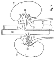
図3は、ヒトの腎臓の解剖学的構造内に配設された図1の血管内デバイス110を示している。ヒトの腎臓の解剖学的構造は、腎臓の口92で腹大動脈90から分岐して腎臓10の門95に入る左右腎動脈81によって、酸素化血液が供給されている腎臓10を含む。腹大動脈90は腎動脈81を心臓(図示せず)に接続する。脱酸素化血液は、腎静脈101及び下行大静脈111を介して、腎臓10から心臓に流れる。具体的には、腹大動脈を通って左腎動脈81内へと延在する、血管内デバイス110の可撓性の細長い部材170が示されている。代替実施形態では、血管内デバイス110は、下方の腎血管115も通って移動するようにサイズ決めされ構成される。具体的には、腹大動脈を通って左腎動脈81内へと延在する、血管内デバイス110が示されている。代替実施形態では、血管内デバイス110は、下方の腎血管115も通って移動するようにサイズ決めされ構成される。
FIG. 3 shows the
左右の腎神経叢又は神経121は、左右腎動脈81をそれぞれ取り囲む。解剖学的に、腎神経121は、腎動脈81を取り囲む外膜細胞内の1つ又は複数の神経叢を形成する。本開示の目的のため、腎神経は、任意の個別の神経又は神経叢及び神経節として定義され、それらは、神経信号を腎臓10との間でやり取りし、解剖学的には、腎動脈81の表面上、腎動脈81が大動脈90から分岐する腹大動脈90の部分、及び/又は腎動脈81の下方の分岐上に位置する。神経叢に寄与する神経線維は、腹腔神経節、最下内蔵神経、腎皮質神経節、及び大動脈神経叢から生じる。腎神経121は、それぞれの腎動脈と密接に関連して、それぞれの腎臓10の基質内まで延在する。神経は、腎動脈の分枝によって、腎臓10の血管、糸球体、及び細管に分配される。各腎神経221は、一般に、腎臓の門95の範囲でそれぞれの腎臓10に入るが、腎動脈81、又は腎動脈81の分枝が腎臓10に入る位置を含む任意の位置で、腎臓10に入ることができる。
The left and right renal plexuses or
適切な腎機能は、高血圧症状を回避するために、心疾患ホメオスタシスを維持するために必須である。ナトリウムの排出は、適切な細胞外流体量及び血液量を維持し、最終的に流体量及び血液量の影響を最制御する鍵である。定常状態下で、動脈圧力は、尿量と水及びナトリウムの摂取とのバランスをもたらす圧力レベルまで上昇する。異常な腎臓機能によって、腎神経121による腎臓の交感神経過剰刺激によって起こるように、腎臓がナトリウム及び水を過度に保持している場合、動脈圧力は、ナトリウム排出を摂取に等しい量に維持するレベルまで増加する。高血圧患者では、ナトリウムの摂取と排出のバランスは、部分的には腎神経121による腎臓の交感神経刺激の結果として、動脈圧力の上昇を犠牲にして達成される。腎除神経術は、腎臓10の遠心性及び求心性交感神経活性を遮断又は抑制することによって、高血圧の症状及び後遺症を緩和する助けとなる。
Proper renal function is essential to maintain heart disease homeostasis to avoid hypertensive symptoms. Sodium drainage is the key to maintaining proper extracellular fluid and blood volumes and ultimately controlling the effects of fluid and blood volumes. Under steady state conditions, arterial pressure rises to a pressure level that results in a balance between urine volume and water and sodium intake. If the kidneys are holding too much sodium and water, as caused by abnormal sympathetic hyperstimulation of the kidney by the
いくつかの実施形態では、図1及び図2の血管80は、図3の血管81と一致する腎血管であり、脈波伝播速度は腎動脈内で決定される。処理システム130は、腎動脈内の脈波伝播速度(PWV)を決定する。処理システム130は、腎動脈の脈波伝播速度に基づいて、腎除神経療法の推奨を決定する。例えば、腎除神経術から治療的利益を得やすい、又は得にくい患者が、PWVに基づいて選択される。その点に関して、腎血管内の血液のPWVに少なくとも部分的に基づいて、処理システム130は、腎除神経術のための患者階層化を行うことができる。
In some embodiments, the
図4は、血管を通って移動する脈波と関連付けられる血管壁までの距離の測定値のグラフ400である。グラフ400は、血管を通って移動する流体、例えば血液の曲線402を示している。横軸404は時間を表し、縦軸406はセンサ(例えば、撮像素子)から血管壁までの距離を任意単位で表す。例えば、グラフ400は、それぞれ約1秒かかる(毎分約60拍の心拍に対応する)2つの完全なパルスを示している。一例として、図4の曲線402は、特定の地点における、例えば血管80内部のセンサ202、204、又は206の位置における、時間の関数としての脈波を表す。いくつかの実施形態では、脈波は、ピーク410、トラフ412、切痕(例えば、重複切痕)、最小値、最大値、値の変化、及び/又は認識可能なパターンを含む、距離曲線402の特定の様相又は特性によって特定される。それに加えて、脈波は、フット間(foot−to−foot)解析によって、又はその全体を参照により本明細書に援用する、SolaらのPhysiological Measurement、vol.30、pp.603−615、2009に記載されているような、パルス波形からのパルス到着時間の専用解析によって特定される。或いは、相互相関解析、位相変換方法、最大尤度推定量、適応最小二乗平均フィルタ、平均平方差関数、又は複数信号分類(MUSIC)アルゴリズムなど、時間遅延推定に関する更に一般的な方法が、圧力波間の時間遅延を評価するのに適用される。いくつかの実施形態では、センサ202、204、206は、血管80の直径の変化によって、又はセンサ202、204、及び206と血管80の壁との距離の変化によって、脈波を特定するように構成される。このセンサデータは、血管80内の局所PWVを決定するのに使用される。任意に、PWV値はその後、腎除神経術に適格か又は適格でないかに関して高血圧患者の階層化に使用される。
FIG. 4 is a
曲線402は、ある観点において血管内の圧力波に対応する。即ち、血管内の圧力波は、センサ202、204と血管壁との間の距離のばらつきの変化を引き起こす。センサ202、204が圧力を直接測定する必要はなく、それよりもむしろ、センサ202、204によって得られたイメージングデータを使用して、圧力波によって生じる血管壁までの変動する距離を決定する。
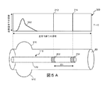
図5A、図5B、及び図5Cは、血管80内の血管壁曲線までの撮像素子の距離を示すグラフと組み合わされた、血管80内における例示の血管内デバイス110の斜視図を示している。距離曲線は、図4に関連して考察したような、血管80を通って移動する脈波と関連付けられる。図5Aの例では、グラフ500の曲線502は、脈波が撮像素子の位置を時間T=0の時に移動している際の、血管壁までの撮像素子の距離を示している。脈波による圧力が、血管壁の移動する膨張510をもたらす。特に、脈波が血管80を通って移動するにつれて、増加した圧力が血管80のわずかな拡幅をもたらす。この膨張510は、第1及び第2のセンサ202、204によって、血管直径の増加として測定される。
5A, 5B, and 5C show perspective views of an exemplary
図5Bは、その後の時間T=T1における血管を示している。この例では、脈波は右に移動しており、グラフ514上の距離曲線512のピークは地点212でセンサ202と位置合わせされている。この時間T=T1において、センサ202は、血管80の直径の最大増加、又は膨張510として見えるセンサと血管の壁との最大距離を読み取り、地点212において脈波の最大圧力が存在することが示される。
FIG. 5B shows the blood vessel at a subsequent time T = T1. In this example, the pulse wave is moving to the right, and the peak of
図5Cは、その後の時間T=T2(T2=T1+ΔT)における距離曲線のグラフを示している。グラフ520上の距離曲線522のピークは、地点214でセンサ204と位置合わせされる。したがって、時限ΔTにおいて、脈波はセンサ202とセンサ204との間の距離D1を移動している。この距離D1を時限ΔTで割ることによって、PWVが計算される。即ち、
腎動脈81などの一部の血管は長さが限定されているため、センサ202、204は、精度をより良好にするため、高頻度でイメージングデータを収集するように構成される。例えば、PWVを計算する際に上記の例によるデータを使用して、精度90%のPWVを達成するには、血管内システム100は20m/sと18m/sとを区別できなければならない。速度が18m/秒の場合、脈波がセンサ202、204に到達する間の時限ΔTは、(0.02m)/(18m/s)=1.11msである。したがって、これらのPWV値を区別するために、血管内システム100は、1msと1.11msとの時限ΔTを区別できなければならず、したがって約0.1msの単位で区別できなければならない。超音波変換器のサンプリング周波数は、超音波ビームが変換器から血管壁に伝播して戻るのに要する時間によって限定される。一般的に、腎動脈の直径は5〜6mmである。変換器が壁に接して配置された場合、超音波は血管直径を横切って二度移動しなければならない。最悪のケースの伝播距離15mmを仮定し、約1.570m/sの血中の音速を所与とすると、超音波が反対側の血管壁まで移動して戻るのに0.0096msかかる。これは、PWVの決定に要する0.1msの約10分の1であり、最大105kHzのサンプル速度に達することができる。血管内システム100は、100kHz単位のサンプリング周波数(0.01ms毎に1回の測定)を達成することができ、0.1msの遅延を検出することが可能になっている。好ましくは、第1及び第2の撮像素子202、204のサンプリング周波数は、10kHz以上、より好ましくは20kHz以上、最も好ましくは40kHz以上である。いくつかの実施形態では、血管内システム100のサンプリング周波数は、10〜80kHz、20〜70kHz、又は40〜60kHzである。他の範囲のサンプリング周波数も可能である。
Because some blood vessels, such as the
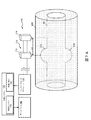
いくつかの実施形態では、PWVは、血管壁における移動を直接測定することによって決定される。血管壁の移動を使用して、血管における脈波の位置が特定される。いくつかの実施形態では、血管壁速度は、ドップラーイメージングを使用してセンサで測定される。特に、血管壁の移動は、センサ202、204によって2つ以上の位置で測定される。様々なセンサによって測定されるような壁速度と関連付けられた時間遅延を比較することによって、PWVが決定される。
In some embodiments, PWV is determined by directly measuring movement in the vessel wall. Movement of the blood vessel wall is used to locate the pulse wave in the blood vessel. In some embodiments, vessel wall velocity is measured at the sensor using Doppler imaging. In particular, movement of the blood vessel wall is measured by the
図6は、血管壁までの距離を測定する2つのセンサ202及び204の距離測定と関連付けられた2つのグラフを示している。グラフ600は、流体、例えば血液の圧力波が、血管内のセンサ202の位置P1で血管を通って移動するときの、撮像素子202と血管壁との間の距離の距離曲線602を示している。グラフ610は、脈波がセンサ204の位置P2で血管を通って移動するときの、撮像素子204と血管壁との間の距離の距離曲線604を示している。いくつかの実施形態では、距離曲線602、604は、第1及び第2のセンサ202、204などのセンサからデータを収集して解析することにより、血管内システム100によって決定される。いくつかの例では、第2の位置P2は、第1の位置よりも流体流の遠位側又は下流側である。グラフ600及び610の横軸612は時間を表し、縦軸614は血管壁までの距離を表す。図示されるように、グラフ600の距離曲線602は時間T1で始まり、グラフ610の距離曲線604は時間T2で始まり、ΔT=T2−T1は、流体の脈波が、グラフ600と関連付けられた第1の位置からグラフ610と関連付けられた第2の位置まで移動するのにかかる時限を表す。このように、図6のグラフ600及び610は、血管80に沿って移動する脈波を示しており、脈波は、第1のモニタリング位置P1と第2のモニタリング位置P2との間を移動するのにΔT秒かかる。この時限ΔTを使用して、図5A及び図5Bを参照して説明したように、血管80における脈波のPWVが計算される。いくつかの例では、曲線602、604を比較してΔTが決定されるが、その比較は、ピーク、トラフ、切痕(例えば、重複切痕)、最小値、最大値、値の変化、及び/又は認識可能なパターンを含む、多数の様相によって遂行される。
FIG. 6 shows two graphs associated with the distance measurement of the two
いくつかの実施形態では、距離曲線602、604の位相は、所与の時間におけるセンサ202、204の測定値を比較することによって特定される。例えば、センサ202は、ある時間間隔にわたる、血管直径の変動、又はセンサ202とセンサ202に面している血管の壁との距離の変動を示す、イメージングデータを収集する。いくつかの実施形態では、センサ202、204の1つ又は複数の活性化は、センサ202、204によって測定される距離曲線602、604が同じ位相を有するように遅延される。次に、距離曲線602、604の位相を一致させるのに必要な遅延は、PWVの計算に使用される。いくつかの実施形態では、距離曲線602、604の位相は、第1及び第2のセンサ202、204を同時に作動させ、センサ202、204からの血管直径を比較することによって決定される。この方法は、センサ202、204によって測定される血管直径の差がゼロのときを特定することによって、遅延を決定することを含む。いくつかの実施形態では、センサ202、204の活性化は、(図1及び図2に示されるような)インターフェースモジュール120又は処理システム130の1つ又は複数によって制御され、それにはセンサの活性化を特定の時限遅延させることが含まれる。
In some embodiments, the phase of distance curves 602, 604 is identified by comparing the measurements of
図7A及び図7Bは、PWVを測定するように構成された例示の測定システム700の概略図である。測定システム700は、血管80外に位置決めされる外部デバイス710と、インターフェースモジュール120と、少なくとも1つのプロセッサ140及び少なくとも1つのメモリ150を有する処理システム130と、ディスプレイ160とを含み、それらは図1の構成要素と同様であってもよい。いくつかの実施形態では、外部デバイス710は、血管80の様相を外部位置から測定するように構成された、2つ以上のセンサ712、714を含む。センサ712、714は、第1、第2、及び第3のセンサ202、204、206と類似の超音波変換器である。いくつかの実施形態では、センサ712、714は、患者の組織620を通して測定し、血管80の直径又は血管壁の位置の変化を決定する。図7Aの例では、脈波は、第1のセンサ712下で心出しされ、これは血管壁の膨張510によって見ることができる。図7Bでは、脈波及び関連する膨張510は距離D1移動しており、第2のセンサ714下で心出しされている。センサ712、714の間の距離D1、及び膨張510の測定の時間差は、脈波のPWVを決定するのに使用される。
7A and 7B are schematic diagrams of an
図8は、血管80内に配設された血管内デバイス110が、血管80内の距離曲線を示すグラフ400と組み合わされている、例示の血管内システム800の概略図である。いくつかの実施形態では、脈波は、血管系に接合部又は分岐820が存在することを含む様々な理由で、血管80内で反射されている。この反射によって、脈波が血管80を通って様々な方向に移動し、それが局所PWV値の測定値と干渉する。しかしながら、いくつかの実施形態では、血管内デバイス110は3つ以上のセンサ202、204、206を含み、それにより、位置212、214、及び216をそれぞれモニタリングすることによって、後方移動する脈波を特定し排除することが可能になっている。特に、第3のセンサ206は、前方移動する脈波(曲線802及び膨張510aによって示される)を後方移動する脈波(曲線812及び膨張510bによって示される)と区別するのに使用される。いくつかの実施形態では、脈波の方向性の決定は、3つ以上のセンサ202、204、206からの超音波測定値を相関させて、各脈波の始まりと終わりを特定することによって遂行される。脈波の増幅、及びそれに対応する膨張510a、510bの幅も、方向性の決定に使用される。例えば、距離曲線812及び膨張510bによって示されるような後方移動する脈波は、距離曲線802及び膨張510aによって示されるような前方移動する脈波よりも小さい振幅を有する。いくつかの実施形態では、前方移動する脈波と及び後方移動する脈波の分離によって、PWV計算の精度が改善する。
FIG. 8 is a schematic view of an exemplary
図9は、脈波伝播速度(PWV)を計算する方法900を示すフローチャートである。ステップ902で、方法900は、血管内デバイスを血管内に配置することを含む。いくつかの実施形態では、血管内デバイスは、図1、図2、図5A、図5B、図5C、及び図8に示される血管内デバイス110である。血管は、図3に示されるような腎動脈81である。
FIG. 9 is a flow chart illustrating a
ステップ904で、方法900は、血管内デバイス上で第1の距離離間して配設された第1及び第2のセンサを活性化させることを含む。第1及び第2のセンサは可撓性の細長い部材上に配設される。他の実施形態では、第1及び第2のセンサは、図7A及び図7Bの例など、患者の体外に配設される。いくつかの実施形態では、血管内イメージング(例えば、血管内超音波、回転式血管内超音波、整相列血管内超音波、又は光コヒーレント断層撮影)が、血管直径、又はセンサとセンサに面する血管壁との間の距離など、血管内の測定値のモニタリングに使用される。いくつかの実施形態では、第1及び第2のセンサの少なくとも1つは超音波変換器である。他の実施形態では、第1及び第2のセンサの少なくとも1つは、ミラー、レンズ、プリズムなどの光学撮像素子である。第1及び第2のセンサの間の距離は、PWVの計算に使用される。第1及び第2のセンサは、カテーテル又はガイドワイヤなど、可撓性の細長いデバイスの遠位側部分上に配設される。いくつかの実施形態では、外部プローブ(例えば、超音波イメージング及び/又はドップラーフロー)が、血管直径のモニタリングに使用される。
At
ステップ906で、方法900は、血管の直径などの測定値の変化を、第1のセンサで第1の時間に測定することを含む。同様に、第1のセンサと血管壁との間の距離の変化を測定することができる。いくつかの実施形態では、血管の直径の変化、又は第1のセンサと血管壁との間の距離の変化は、脈波の存在を知らせる膨張又は膨らみである。変化は、特定の特徴、例えば直径のピーク又は距離のピークであることができる。
At
ステップ908で、方法900は、血管の直径などの測定値の変化を、第2のセンサで第2の時間に測定することを含む。同様に、第2のセンサと血管壁との間の距離の変化を測定することができる。血管の直径のこの変化、又は第2のセンサと血管壁との間の距離の変化も、脈波の存在を知らせる膨張又は膨らみである。変化は、第1のセンサに関してステップ906で使用したのと同じ特定の特徴、例えば直径のピーク又は距離のピークであることができる。いくつかの実施形態では、脈波の移動方向は、例えば、膨張の大きさを測定することによって、又は追加のセンサによって血管の直径の変化を測定することによって決定される。(図8に関連して示したような)後方方向に移動する脈波は、PWV決定の精度を改善するため、計算から除外される。
At
ステップ910で、方法900は、第1及び第2の時間の差を計算することを含む。この差は、図5C及び図6に関連して示した時限ΔTの計算と同様である。この計算は、第1及び第2のセンサと連通しているコントローラによって実施される。
At
ステップ912で、方法900は、第1の距離を第1及び第2の時間の差で割って、PWVを決定することを含む。
At
ステップ914で、方法900は、任意に、PWVをディスプレイに出力することを含む。このディスプレイは、図1及び図2に示されるディスプレイ160である。いくつかの実施形態では、PWVを使用して、患者に対する腎除神経術の潜在的効果が評価され、それが、腎除神経術が有益であろう患者を選択する助けとなる。
At
いくつかの実施形態では、方法900は任意に、PWVに基づいて療法の推奨を決定することを含む。いくつかの例では、臨床医は、計算されたPWV及び/又は他の患者データに基づいて療法の推奨を決定する。いくつかの実施形態では、処理システムは、PWV及び/又は他の患者データを評価して、療法の推奨を決定する。かかる例では、方法900は、療法の推奨の視覚的表現を出力することを含む。例えば、処理システムは、図式的表現と関連付けられた表示データを表示デバイスに出力することができる。「不良」、「可」、「良」などの文字による指示であることができ、及び/又は他の適切な単語が、特定の患者に対する療法と関連付けられた予測される効果を伝達する。他の例では、点数、色分け、及び/又は療法の推奨を表す他の図形を、ディスプレイに出力することができる。いくつかの例では、療法は腎除神経術であることができる。方法900は更に、PWVに基づいて、1人又は複数人の患者を、腎除神経術の結果として予測される治療効果のそれぞれの程度に対応するグループに分類することを含むことができる。方法900はまた、処理システムが分類ステップの図形的表現を表示デバイスに出力することを含むことができる。
In some embodiments, the
当業者であれば、本開示に包含される実施形態は上述した特定の例示的実施形態に限定されないことを理解するであろう。その点に関して、例証となる実施形態を図示し記載してきたが、広範囲の修正、変更、及び置換が上述の開示において想到される。かかる変形は、本開示の範囲から逸脱することなく、上記に対して行われることが理解される。したがって、添付の特許請求の範囲は概括的に、また本開示と一貫した形で解釈されることが適切である。 Those skilled in the art will appreciate that the embodiments encompassed by the present disclosure are not limited to the specific exemplary embodiments described above. In that regard, while illustrative embodiments have been shown and described, a wide range of modifications, alterations, and substitutions are contemplated in the foregoing disclosure. It is understood that such modifications may be made to the above without departing from the scope of the present disclosure. Accordingly, it is appropriate that the appended claims be construed broadly and in a manner consistent with the present disclosure.
Claims (17)
前記血管内デバイスは、
近位側部分及び遠位側部分を有する可撓性の細長い部材と、
前記可撓性の細長い部材の前記遠位側部分に結合され、第1の位置で前記血管内の測定値をモニタリングする第1の撮像素子と、
前記可撓性の細長い部材の長さに沿って第1の距離だけ前記第1の撮像素子から離間した位置で、前記可撓性の細長い部材の前記遠位側部分に結合され、前記第1の位置から離間した第2の位置で前記血管内の前記測定値をモニタリングする第2の撮像素子とを含み、
前記処理システムは、
前記第1の撮像素子による前記血管内の前記第1の位置における前記血管の前記測定値の前記モニタリングと関連付けられた第1のデータを受信し、
前記第2の撮像素子による前記血管内の前記第2の位置における前記血管の前記測定値の前記モニタリングと関連付けられた第2のデータを受信し、
受信した前記第1及び第2のデータに基づいて、前記血管内の流体の脈波伝播速度を決定し、
前記血管が腎動脈であり、前記第1及び第2の撮像素子のサンプリング周波数が、10kHz以上、より好ましくは20kHz以上、最も好ましくは40kHz以上である、装置。 An apparatus for determining a pulse wave velocity (PWV) in a blood vessel comprising an intravascular device positioned in a blood vessel and a processing system in communication with the intravascular device, comprising:
The intravascular device is
A flexible elongated member having a proximal portion and a distal portion;
A first imaging device coupled to the distal portion of the flexible elongate member for monitoring measurements in the blood vessel at a first position;
Coupled to the distal portion of the flexible elongate member at a position spaced apart from the first imaging element by a first distance along a length of the flexible elongate member; A second imaging device monitoring the measurements in the blood vessel at a second position spaced from the position of
The processing system
Receiving first data associated with the monitoring of the measurement of the blood vessel at the first position in the blood vessel by the first imaging device;
Receiving second data associated with the monitoring of the measurement of the blood vessel at the second position in the blood vessel by the second imaging device;
Determining a pulse wave velocity of fluid in the blood vessel based on the received first and second data;
The apparatus, wherein the blood vessel is a renal artery, and the sampling frequency of the first and second imaging elements is 10 kHz or more, more preferably 20 kHz or more, and most preferably 40 kHz or more.
第2の撮像素子によって、前記血管の長さに沿って第1の距離だけ前記第1の位置から離間した前記血管の第2の位置における、前記血管の測定値をモニタリングするステップと、
前記第1の撮像素子による前記第1の位置における前記血管の前記測定値の前記モニタリングと関連付けられた第1のデータを受信するステップと、
前記第2の撮像素子による前記第2の位置における前記血管の前記測定値の前記モニタリングと関連付けられた第2のデータを受信するステップと、
前記受信した第1及び第2のデータに基づいて、前記血管内の流体の脈波伝播速度を決定するステップとを含み、
前記血管が腎動脈であり、前記第1及び第2の撮像素子のサンプリング周波数が、10kHz以上、より好ましくは20kHz以上、最も好ましくは40kHz以上である、血管内の脈波伝播速度(PWV)を決定する、方法。 Monitoring a measurement of the blood vessel at a first position of the blood vessel by a first imaging device;
Monitoring the measurement of the blood vessel at a second position of the blood vessel spaced apart from the first position by a first distance along a length of the blood vessel by a second imaging element;
Receiving first data associated with the monitoring of the measurement of the blood vessel at the first position by the first imaging device;
Receiving second data associated with the monitoring of the measurement of the blood vessel at the second position by the second imaging device;
Determining a pulse wave velocity of fluid in the blood vessel based on the received first and second data.
The pulse wave velocity (PWV) in a blood vessel is a renal artery, and the sampling frequency of the first and second imaging elements is 10 kHz or more, more preferably 20 kHz or more, and most preferably 40 kHz or more. How to decide.
Applications Claiming Priority (5)
| Application Number | Priority Date | Filing Date | Title |
|---|---|---|---|
| EP16170662 | 2016-05-20 | ||
| EP16170662.7 | 2016-05-20 | ||
| EP16176911 | 2016-06-29 | ||
| EP16176911.2 | 2016-06-29 | ||
| PCT/EP2017/062196 WO2017198867A1 (en) | 2016-05-20 | 2017-05-19 | Devices and methods for determining pulse wave velocity based on changes in vessel diameter |
Publications (2)
| Publication Number | Publication Date |
|---|---|
| JP2019516476A true JP2019516476A (en) | 2019-06-20 |
| JP2019516476A5 JP2019516476A5 (en) | 2020-06-25 |
Family
ID=58737581
Family Applications (1)
| Application Number | Title | Priority Date | Filing Date |
|---|---|---|---|
| JP2018560154A Pending JP2019516476A (en) | 2016-05-20 | 2017-05-19 | Device and method for determining pulse wave velocity based on changes in blood vessel diameter |
Country Status (5)
| Country | Link |
|---|---|
| US (1) | US20190175035A1 (en) |
| EP (1) | EP3457911A1 (en) |
| JP (1) | JP2019516476A (en) |
| CN (1) | CN109152533A (en) |
| WO (1) | WO2017198867A1 (en) |
Families Citing this family (30)
| Publication number | Priority date | Publication date | Assignee | Title |
|---|---|---|---|---|
| US10610292B2 (en) | 2014-04-25 | 2020-04-07 | Medtronic Ardian Luxembourg S.A.R.L. | Devices, systems, and methods for monitoring and/or controlling deployment of a neuromodulation element within a body lumen and related technology |
| JP6924701B2 (en) | 2015-02-12 | 2021-08-25 | ファウンドリー イノベーション アンド リサーチ 1,リミテッドFoundry Innovation & Research 1,Ltd. | Portable Devices and Related Methods for Monitoring Heart Failure |
| EP3331426A1 (en) | 2015-08-03 | 2018-06-13 | Foundry Innovation&Research 1, Ltd. | Devices and methods for measurement of vena cava dimensions, pressure, and oxygen saturation |
| US10315222B2 (en) | 2016-05-04 | 2019-06-11 | Invensense, Inc. | Two-dimensional array of CMOS control elements |
| US10445547B2 (en) | 2016-05-04 | 2019-10-15 | Invensense, Inc. | Device mountable packaging of ultrasonic transducers |
| US10441975B2 (en) | 2016-05-10 | 2019-10-15 | Invensense, Inc. | Supplemental sensor modes and systems for ultrasonic transducers |
| US10706835B2 (en) | 2016-05-10 | 2020-07-07 | Invensense, Inc. | Transmit beamforming of a two-dimensional array of ultrasonic transducers |
| EP3251591B1 (en) * | 2016-06-02 | 2019-02-27 | Hospices Civils De Lyon | System for determining a coronary pulse wave velocity |
| EP3496606A1 (en) | 2016-08-11 | 2019-06-19 | Foundry Innovation & Research 1, Ltd. | Systems and methods for patient fluid management |
| US11206992B2 (en) | 2016-08-11 | 2021-12-28 | Foundry Innovation & Research 1, Ltd. | Wireless resonant circuit and variable inductance vascular monitoring implants and anchoring structures therefore |
| US11701018B2 (en) | 2016-08-11 | 2023-07-18 | Foundry Innovation & Research 1, Ltd. | Wireless resonant circuit and variable inductance vascular monitoring implants and anchoring structures therefore |
| EP3725214A1 (en) | 2016-11-29 | 2020-10-21 | Foundry Innovation & Research 1, Ltd. | Wireless resonant circuit and variable inductance vascular implants for monitoring patient vasculature system |
| WO2018220146A1 (en) | 2017-05-31 | 2018-12-06 | Foundry Innovation & Research 1, Ltd. | Implantable sensors for vascular monitoring |
| WO2018220143A1 (en) | 2017-05-31 | 2018-12-06 | Foundry Innovation And Research 1, Ltd | Implantable ultrasonic vascular sensor |
| US11413005B2 (en) * | 2017-08-14 | 2022-08-16 | Stryker Corporation | Constitutive equation for non-invasive blood pressure measurement systems and methods |
| GB2570131A (en) * | 2018-01-11 | 2019-07-17 | Imperial Innovations Ltd | Fluid flow analysis |
| WO2019243218A1 (en) * | 2018-06-21 | 2019-12-26 | Koninklijke Philips N.V. | System and method for determining pulse wave velocity of vessels |
| EP3643244A1 (en) * | 2018-10-25 | 2020-04-29 | Koninklijke Philips N.V. | System and method for determining pulse wave velocity of vessels |
| EP3613350A1 (en) * | 2018-08-21 | 2020-02-26 | Koninklijke Philips N.V. | Systems and method for performing pulse wave velocity measurements |
| AU2019328805A1 (en) * | 2018-08-31 | 2021-04-22 | National University Of Ireland Galway | Ultrasound based three-dimensional lesion verification within a vasculature |
| WO2020084140A1 (en) | 2018-10-26 | 2020-04-30 | Koninklijke Philips N.V. | Pulse wave velocity measurement system |
| EP3714780A1 (en) | 2019-03-28 | 2020-09-30 | Koninklijke Philips N.V. | Pulse wave velocity measurement system |
| US20220054029A1 (en) * | 2018-12-17 | 2022-02-24 | Foundry Innovation & Research 1, Ltd. | Pulse Wave Velocity Measurement |
| CN111973227B (en) * | 2019-05-21 | 2024-04-09 | 中国人民解放军第四军医大学 | Noninvasive measurement method for aortic stiffness of rat model |
| US11176345B2 (en) | 2019-07-17 | 2021-11-16 | Invensense, Inc. | Ultrasonic fingerprint sensor with a contact layer of non-uniform thickness |
| US11392789B2 (en) | 2019-10-21 | 2022-07-19 | Invensense, Inc. | Fingerprint authentication using a synthetic enrollment image |
| EP3832662A1 (en) | 2019-12-02 | 2021-06-09 | Koninklijke Philips N.V. | Systems and methods for vascular assessment |
| EP4100176A1 (en) | 2020-03-09 | 2022-12-14 | InvenSense, Inc. | Ultrasonic fingerprint sensor with a contact layer of non-uniform thickness |
| EP3884868A1 (en) * | 2020-03-26 | 2021-09-29 | Pie Medical Imaging BV | Method and system for registering intra-object data with extra-object data |
| WO2022020160A1 (en) * | 2020-07-21 | 2022-01-27 | Edwards Lifesciences Corporation | System and method for non-invasively sensing a blood vessel |
Citations (5)
| Publication number | Priority date | Publication date | Assignee | Title |
|---|---|---|---|---|
| JPH1176233A (en) * | 1997-09-01 | 1999-03-23 | Terumo Corp | Cardiovascular system information measuring system |
| WO1999034724A2 (en) * | 1998-01-12 | 1999-07-15 | Florence Medical Ltd. | Characterizing blood vessel using multi-point pressure measurements |
| US20060058653A1 (en) * | 2004-08-23 | 2006-03-16 | Scimed Life Systems, Inc. | Systems and methods for measuring pulse wave velocity with an intravascular device |
| US20140012133A1 (en) * | 2012-05-31 | 2014-01-09 | CardioSonic Ltd. | Method and/or apparatus for measuring renal denervation effectiveness |
| JP2016508043A (en) * | 2012-12-21 | 2016-03-17 | ヴォルカノ コーポレイションVolcano Corporation | System and method for multi-site intravascular measurements |
Family Cites Families (3)
| Publication number | Priority date | Publication date | Assignee | Title |
|---|---|---|---|---|
| US7559894B2 (en) * | 2003-09-18 | 2009-07-14 | New Paradigm Concepts, LLC | Multiparameter whole blood monitor and method |
| CN101247757A (en) * | 2005-08-26 | 2008-08-20 | 皇家飞利浦电子股份有限公司 | Apparatus and method for defibrillation pulse detection using electromagnetic waves |
| CN100518634C (en) * | 2006-06-05 | 2009-07-29 | 中国科学院力学研究所 | Device and method for measuring pulse waving speed |
-
2017
- 2017-05-19 US US16/301,016 patent/US20190175035A1/en not_active Abandoned
- 2017-05-19 EP EP17724378.9A patent/EP3457911A1/en not_active Withdrawn
- 2017-05-19 JP JP2018560154A patent/JP2019516476A/en active Pending
- 2017-05-19 CN CN201780031127.1A patent/CN109152533A/en active Pending
- 2017-05-19 WO PCT/EP2017/062196 patent/WO2017198867A1/en unknown
Patent Citations (5)
| Publication number | Priority date | Publication date | Assignee | Title |
|---|---|---|---|---|
| JPH1176233A (en) * | 1997-09-01 | 1999-03-23 | Terumo Corp | Cardiovascular system information measuring system |
| WO1999034724A2 (en) * | 1998-01-12 | 1999-07-15 | Florence Medical Ltd. | Characterizing blood vessel using multi-point pressure measurements |
| US20060058653A1 (en) * | 2004-08-23 | 2006-03-16 | Scimed Life Systems, Inc. | Systems and methods for measuring pulse wave velocity with an intravascular device |
| US20140012133A1 (en) * | 2012-05-31 | 2014-01-09 | CardioSonic Ltd. | Method and/or apparatus for measuring renal denervation effectiveness |
| JP2016508043A (en) * | 2012-12-21 | 2016-03-17 | ヴォルカノ コーポレイションVolcano Corporation | System and method for multi-site intravascular measurements |
Non-Patent Citations (1)
| Title |
|---|
| STEIN INGE RABBEN ET AL.: "An ultrasound-based method for determining pulse wave velocity in superficial arteries", JOURNAL OF BIOMECHANICS, vol. 37, JPN6021014369, 26 February 2004 (2004-02-26), pages 1615 - 1622, ISSN: 0004654871 * |
Also Published As
| Publication number | Publication date |
|---|---|
| EP3457911A1 (en) | 2019-03-27 |
| WO2017198867A1 (en) | 2017-11-23 |
| CN109152533A (en) | 2019-01-04 |
| US20190175035A1 (en) | 2019-06-13 |
Similar Documents
| Publication | Publication Date | Title |
|---|---|---|
| JP2019516476A (en) | Device and method for determining pulse wave velocity based on changes in blood vessel diameter | |
| EP3457928B1 (en) | Determining pulse wave velocity using intravascular pressure measurement and external ultrasound imaging, and associated devices, systems, and methods | |
| US20190090856A1 (en) | Devices and methods for stratification of patients for renal denervation based on intravascular pressure and cross-sectional lumen measurements | |
| US20190290139A1 (en) | Apparatus and methods for determining pulse wave velocity using multiple pressure sensors | |
| JP4602972B2 (en) | Ultrasonic diagnostic apparatus and control method of ultrasonic diagnostic apparatus | |
| US20180064411A1 (en) | Method and system for measuring pulmonary artery circulation information | |
| JP7299992B2 (en) | Intraluminal Ultrasound Vessel Boundary Selection and Related Devices, Systems, and Methods | |
| US20190200884A1 (en) | Devices and methods for stratification of patients for renal denervation based on intravascular pressure and wall thickness measurements | |
| JP6783863B2 (en) | Multi-site continuous ultrasonic flow measurement for blood circulation management | |
| JP6148620B2 (en) | Measurement of pulmonary blood pressure using transthoracic Doppler ultrasound | |
| JP2022509401A (en) | Graphical longitudinal display for intraluminal ultrasound imaging, as well as related devices, systems, and methods. | |
| US20230008714A1 (en) | Intraluminal image-based vessel diameter determination and associated devices, systems, and methods | |
| US20210251504A1 (en) | System and method for determining pulse wave velocity of vessels | |
| EP3263018A1 (en) | Devices and methods for stratification of patients for renal denervation based on intravascular pressure and wall thickness measurements | |
| JP2008161546A (en) | Ultrasonic diagnostic apparatus | |
| EP3643244A1 (en) | System and method for determining pulse wave velocity of vessels | |
| Apostolakis | 2-D and 3-D high frame-rate Pulse Wave Imaging for the characterization of focal vascular disease | |
| RU2005416C1 (en) | Method for assessing disturbance of hemodynamics of kidney | |
| RU2465831C1 (en) | Method for assessment of elastic properties of cephalic artery wall |
Legal Events
| Date | Code | Title | Description |
|---|---|---|---|
| A521 | Request for written amendment filed |
Free format text: JAPANESE INTERMEDIATE CODE: A523 Effective date: 20200514 |
|
| A621 | Written request for application examination |
Free format text: JAPANESE INTERMEDIATE CODE: A621 Effective date: 20200514 |
|
| A977 | Report on retrieval |
Free format text: JAPANESE INTERMEDIATE CODE: A971007 Effective date: 20210412 |
|
| A131 | Notification of reasons for refusal |
Free format text: JAPANESE INTERMEDIATE CODE: A131 Effective date: 20210426 |
|
| A02 | Decision of refusal |
Free format text: JAPANESE INTERMEDIATE CODE: A02 Effective date: 20211206 |