JP2019516466A - Insertion tool for inserting a flip anchor cable system - Google Patents
Insertion tool for inserting a flip anchor cable system Download PDFInfo
- Publication number
- JP2019516466A JP2019516466A JP2018559293A JP2018559293A JP2019516466A JP 2019516466 A JP2019516466 A JP 2019516466A JP 2018559293 A JP2018559293 A JP 2018559293A JP 2018559293 A JP2018559293 A JP 2018559293A JP 2019516466 A JP2019516466 A JP 2019516466A
- Authority
- JP
- Japan
- Prior art keywords
- cable
- flip anchor
- insertion tool
- safety button
- handle
- Prior art date
- Legal status (The legal status is an assumption and is not a legal conclusion. Google has not performed a legal analysis and makes no representation as to the accuracy of the status listed.)
- Abandoned
Links
Images


Classifications
-
- A—HUMAN NECESSITIES
- A61—MEDICAL OR VETERINARY SCIENCE; HYGIENE
- A61B—DIAGNOSIS; SURGERY; IDENTIFICATION
- A61B17/00—Surgical instruments, devices or methods, e.g. tourniquets
- A61B17/56—Surgical instruments or methods for treatment of bones or joints; Devices specially adapted therefor
- A61B17/58—Surgical instruments or methods for treatment of bones or joints; Devices specially adapted therefor for osteosynthesis, e.g. bone plates, screws, setting implements or the like
- A61B17/88—Osteosynthesis instruments; Methods or means for implanting or extracting internal or external fixation devices
- A61B17/8861—Apparatus for manipulating flexible wires or straps
-
- A—HUMAN NECESSITIES
- A61—MEDICAL OR VETERINARY SCIENCE; HYGIENE
- A61B—DIAGNOSIS; SURGERY; IDENTIFICATION
- A61B17/00—Surgical instruments, devices or methods, e.g. tourniquets
- A61B17/56—Surgical instruments or methods for treatment of bones or joints; Devices specially adapted therefor
- A61B17/58—Surgical instruments or methods for treatment of bones or joints; Devices specially adapted therefor for osteosynthesis, e.g. bone plates, screws, setting implements or the like
- A61B17/88—Osteosynthesis instruments; Methods or means for implanting or extracting internal or external fixation devices
- A61B17/8872—Instruments for putting said fixation devices against or away from the bone
-
- A—HUMAN NECESSITIES
- A61—MEDICAL OR VETERINARY SCIENCE; HYGIENE
- A61B—DIAGNOSIS; SURGERY; IDENTIFICATION
- A61B17/00—Surgical instruments, devices or methods, e.g. tourniquets
- A61B17/56—Surgical instruments or methods for treatment of bones or joints; Devices specially adapted therefor
- A61B17/58—Surgical instruments or methods for treatment of bones or joints; Devices specially adapted therefor for osteosynthesis, e.g. bone plates, screws, setting implements or the like
- A61B17/68—Internal fixation devices, including fasteners and spinal fixators, even if a part thereof projects from the skin
- A61B17/683—Internal fixation devices, including fasteners and spinal fixators, even if a part thereof projects from the skin comprising bone transfixation elements, e.g. bolt with a distal cooperating element such as a nut
-
- A—HUMAN NECESSITIES
- A61—MEDICAL OR VETERINARY SCIENCE; HYGIENE
- A61B—DIAGNOSIS; SURGERY; IDENTIFICATION
- A61B17/00—Surgical instruments, devices or methods, e.g. tourniquets
- A61B17/56—Surgical instruments or methods for treatment of bones or joints; Devices specially adapted therefor
- A61B17/58—Surgical instruments or methods for treatment of bones or joints; Devices specially adapted therefor for osteosynthesis, e.g. bone plates, screws, setting implements or the like
- A61B17/68—Internal fixation devices, including fasteners and spinal fixators, even if a part thereof projects from the skin
- A61B17/685—Elements to be fitted on the end of screws or wires, e.g. protective caps
-
- F—MECHANICAL ENGINEERING; LIGHTING; HEATING; WEAPONS; BLASTING
- F16—ENGINEERING ELEMENTS AND UNITS; GENERAL MEASURES FOR PRODUCING AND MAINTAINING EFFECTIVE FUNCTIONING OF MACHINES OR INSTALLATIONS; THERMAL INSULATION IN GENERAL
- F16C—SHAFTS; FLEXIBLE SHAFTS; ELEMENTS OR CRANKSHAFT MECHANISMS; ROTARY BODIES OTHER THAN GEARING ELEMENTS; BEARINGS
- F16C1/00—Flexible shafts; Mechanical means for transmitting movement in a flexible sheathing
- F16C1/10—Means for transmitting linear movement in a flexible sheathing, e.g. "Bowden-mechanisms"
- F16C1/12—Arrangements for transmitting movement to or from the flexible member
-
- A—HUMAN NECESSITIES
- A61—MEDICAL OR VETERINARY SCIENCE; HYGIENE
- A61B—DIAGNOSIS; SURGERY; IDENTIFICATION
- A61B17/00—Surgical instruments, devices or methods, e.g. tourniquets
- A61B17/56—Surgical instruments or methods for treatment of bones or joints; Devices specially adapted therefor
- A61B17/58—Surgical instruments or methods for treatment of bones or joints; Devices specially adapted therefor for osteosynthesis, e.g. bone plates, screws, setting implements or the like
- A61B17/68—Internal fixation devices, including fasteners and spinal fixators, even if a part thereof projects from the skin
- A61B2017/681—Alignment, compression, or distraction mechanisms
Abstract
フリップアンカーケーブルを配備するための挿入用具であって、該挿入用具は、安全ボタンとスライダとを有する機構であって、機構が第1の位置にあるときに、フリップアンカーケーブルの一部分に締付け力を加えるように構成されている、機構と、機構に連結された近位端部を有するインナーチューブであって、フリップアンカーケーブルの第2の部分を収容するように構成されている、インナーチューブと、安全ボタン開口部とスライダ開口部とを含んだハンドルであって、機構の一部分を囲むように構成されている、ハンドルと、ハンドルに連結された近位端部を有するアウターチューブであって、インナーチューブを受容するように構成されている、アウターチューブと、を備える。この機構は、機構が第2の位置にあるときにフリップアンカーケーブルにかかる締付け力を低下させるように、また第2の位置においてフリップアンカーケーブルのフリップアンカーを配備するように構成されている。An insertion tool for deploying a flip anchor cable, the insertion tool being a mechanism having a safety button and a slider, wherein a clamping force is applied to a portion of the flip anchor cable when the mechanism is in the first position. An inner tube having a mechanism and a proximal end coupled to the mechanism, the inner tube being configured to receive a second portion of the flip anchor cable A handle comprising a safety button opening and a slider opening, the outer tube having a handle and a proximal end connected to the handle, the handle being configured to surround a portion of the mechanism; And an outer tube configured to receive the inner tube. The mechanism is configured to reduce the clamping force on the flip anchor cable when the mechanism is in the second position and to deploy the flip anchor of the flip anchor cable in the second position.
Description
本明細書で開示される種々の例示的な実施形態は、広義には、フリップアンカーケーブルを挿入するための挿入用具に関するものである。 The various exemplary embodiments disclosed herein relate generally to insertion tools for inserting flip anchor cables.
骨片、2つ以上の骨、又は軟組織と骨との組合せなど、2つ以上の要素を互いに固着させることは、整形外科手技における一般的な要件である。これは、2つの骨片に貫入し、ナットを使用してこれらのセグメントを互いに引き寄せる骨ボルト、骨ねじ、及び相互連結プレート、少なくとも2つの骨片を囲むワイヤ、又は組織の中への縫合糸など、多数のデバイスによって達成されてきた。 Bonding two or more elements together, such as bone fragments, two or more bones, or a combination of soft tissue and bone, is a common requirement in orthopedic procedures. It penetrates two bone fragments and uses a nut to pull the segments together, bone screws, bone screws, and interconnecting plates, wires surrounding at least two bone fragments, or sutures into tissue Etc has been achieved by a large number of devices.
多くの場合、そのようなデバイスは、固着デバイスを埋め込むために、周囲の組織及び/又は被覆する組織を貫く比較的大きなアクセス開口部を必要とする。拡大されたアクセス部位は、患者の疼痛を増大させ、回復時間を長引かせ得る。更に、いくつかの個所では、周囲の関節及び血管により、適切な部位に到達するために大きなアクセスポイントを形成することは困難かつ非実用的となる。実質的に直線的な方式で組織に貫入するデバイス、すなわち、ラグボルトを用いた場合でも、穿孔及びボルトの挿入の前の欠損は多くの場合、低減されなければならない。更に、2つの骨セグメントの間の欠損を低減し、デバイスが挿入される間もその低減を維持することは困難となり得るので、これらのデバイスの一部は使用することが困難となり得る。このことは、ねじ付き移植片を使用すると、一方の骨セグメントをもう一方の骨セグメントに対して回転させがちとなり、それによって骨片の間の誤整列が生じ得る小さな骨片に特に当てはまる。 Often, such devices require a relatively large access opening through the surrounding tissue and / or the covering tissue in order to implant the anchoring device. The expanded access site can increase patient pain and prolong recovery time. Furthermore, in some places, surrounding joints and blood vessels make it difficult and impractical to form a large access point to reach the appropriate site. Even with devices that penetrate tissue in a substantially linear manner, i.e., lag bolts, the defects prior to drilling and insertion of the bolt often must be reduced. Furthermore, some of these devices can be difficult to use, as it may be difficult to reduce the defects between the two bone segments and maintain the reduction even while the device is being inserted. This is especially true for small bone fragments that tend to rotate one bone segment relative to the other bone segment using a threaded implant, which can result in misalignment between the bone fragments.
セルクラージュシステムは、固定を達成するために骨に貫入されなければならない移植片に代わるものである。これらのシステムは、2つの骨のセグメントの周りにケーブルを通し、次いでケーブルに張力をかけて骨セグメントを互いに圧迫することを利用している。これらのシステムの重大な欠点は、骨全体にわたるアクセスを必要とすることである。 The cerclage system is an alternative to implants that must be penetrated into the bone to achieve fixation. These systems utilize passing a cable around two bone segments and then tensioning the cables to compress the bone segments together. A significant disadvantage of these systems is the need for access across the bone.
フリップアンカーケーブルシステムは、2つの組織のセグメントを互いに固着するための好都合でかつ効果的なシステムを提供する。そのようなシステムは、比較的小さな挿入開口部(複数可)を通じて2つの組織セグメントをしっかりと保持するように動作可能となり得る。 The flip anchor cable system provides a convenient and effective system for securing two tissue segments together. Such systems may be operable to hold two tissue segments securely through relatively small insertion opening (s).
各種の例示の実施形態の簡単な概要が、以下に提示される。以下の概要では、いくつかの単純化及び省略が行われることがあり、これらは、各種の例示の実施形態のいくつかの態様を強調及び紹介するためであり、本発明の範囲を限定することを意図しない。当業者が本発明の概念を作り上げ、使用することができるようにするのに適切な例示の実施形態に関する詳細な説明が、この後の各項に続く。 A brief summary of various exemplary embodiments is presented below. In the following summary, some simplifications and omissions may be made, which are to highlight and introduce some aspects of the various exemplary embodiments, and to limit the scope of the present invention. Not intended. A detailed description of exemplary embodiments suitable for enabling those skilled in the art to make and use the inventive concept follow the subsequent sections.
種々の実施形態は、フリップアンカーケーブルを配備するための挿入用具であって、安全ボタンとスライダとを有する機構であって、機構が第1の位置にあるときに、フリップアンカーケーブルの一部分に締付け力を加えるように構成されている機構と、機構に連結された近位端部を有するインナーチューブであって、フリップアンカーケーブルの第2の部分を収容するように構成されている、インナーチューブと、安全ボタン開口部とスライダ開口部とを含んだハンドルであって、機構の一部分を囲むように構成されている、ハンドルと、ハンドルに連結された近位端部を有するアウターチューブであって、インナーチューブを受容するように構成されている、アウターチューブと、を備え、この機構は、機構が第2の位置にあるときにフリップアンカーケーブルにかかる締付け力を低下させるように、また第2の位置においてフリップアンカーケーブルのフリップアンカーを配備するように構成されている、挿入用具に関する。 Various embodiments are an insertion tool for deploying a flip anchor cable, a mechanism having a safety button and a slider, for clamping a portion of the flip anchor cable when the mechanism is in the first position. An inner tube having a mechanism configured to apply a force and an inner tube having a proximal end coupled to the mechanism, the inner tube being configured to receive a second portion of the flip anchor cable A handle comprising a safety button opening and a slider opening, the outer tube having a handle and a proximal end connected to the handle, the handle being configured to surround a portion of the mechanism; An outer tube configured to receive the inner tube, the mechanism being operable when the mechanism is in the second position Tsu to reduce such clamping force to flop anchor cable, and is also configured to deploy flip anchor flip anchor cable in a second position, for an insertion tool.
機構が、安全ボタン突出部と、安全ボタンを押下位置に固定するために安全ボタンが押下されているときに、安全ボタン突出部と係合するように構成された安全ボタンリテーナと、を更に備える、様々な実施形態が記述される。 The mechanism further comprises a safety button protrusion and a safety button retainer configured to engage the safety button protrusion when the safety button is depressed to lock the safety button in the depressed position. , Various embodiments are described.
安全ボタンが押下位置にあることが、スライド力をスライダに加えることによって機構を第2の位置に配置することを可能にする、様々な実施形態が記述される。 Various embodiments are described in which the safety button is in the depressed position, enabling the mechanism to be placed in the second position by applying a sliding force to the slider.
機構が、ケーブル保持部材と、ケーブル保持部材に連結されたケーブル保持突出部であって、第1の位置においてフリップアンカーケーブルに締付け力を加えるように構成されている、ケーブル保持突出部と、を更に備える、様々な実施形態が記述される。 And a cable retention protrusion coupled to the cable retention member, wherein the mechanism is configured to apply a clamping force to the flip anchor cable in the first position. Various embodiments are further described.
ハンドルが、ケーブル保持部材と係合して第1の位置においてフリップアンカーケーブルに締付け力を加えるように構成されたケーブル保持ストッパーを更に備える、様々な実施形態が記述される。 Various embodiments are described in which the handle further comprises a cable retention stop configured to engage the cable retention member to apply a clamping force to the flip anchor cable in the first position.
ケーブル保持部材が、第2の位置においてケーブル保持ストッパーと係合して、機構が第1の位置に復帰することを防止するように構成される、様々な実施形態が記述される。 Various embodiments are described in which the cable retention member is configured to engage the cable retention stopper in the second position to prevent the mechanism from returning to the first position.
機構が、ケーブル保持部材と、ケーブル保持部材に連結されたロッキング部材と、を更に備え、ハンドルが、第2の位置においてロッキング部材と係合して、機構が第1の位置に復帰することを防止するように構成された使い捨てストッパーを更に備える、種々の実施形態が記述される。 The mechanism further comprises a cable holding member and a locking member coupled to the cable holding member, the handle engaging the locking member in the second position to return the mechanism to the first position. Various embodiments are described, further comprising a disposable stopper configured to prevent.
ロッキング部材が、スライド力がスライダに加えられた際に機構が第1の位置から第2の位置へとスライドするとき、ロッキング部材が使い捨てストッパーの上方でスライドすると音を発生させるように構成されている、種々の実施形態が記述される。 The locking member is configured to generate a sound when the locking member slides above the disposable stopper when the mechanism slides from the first position to the second position when the sliding force is applied to the slider Various embodiments are described.
ハンドルがハンドルの外部に方向インジケータを含む種々の実施形態が記述される。 Various embodiments are described in which the handle includes a direction indicator outside the handle.
ハンドルが、ハンドル内部のフリップアンカーケーブルを固定するように構成された複数のケーブルステーを含む、様々な実施形態が記述される。 Various embodiments are described in which the handle includes a plurality of cable stays configured to secure a flip anchor cable within the handle.
ハンドルが、ハンドル内部のフリップアンカーケーブルを展開するのを容易にするように構成された複数のケーブルガイドを含む、様々な実施形態が記述される。 Various embodiments are described in which the handle includes a plurality of cable guides configured to facilitate the deployment of flip anchor cables within the handle.
ハンドルが、ハンドル内部のフリップアンカーケーブルのケーブルロッドを固定するように構成されたケーブルロッド支持体を含む、様々な実施形態が記述される。 Various embodiments are described in which the handle includes a cable rod support configured to secure a cable rod of a flip anchor cable inside the handle.
アウターチューブの遠位端部が、フリップアンカーの近位端部を受容してフリップアンカーを固定するように構成されている、様々な実施形態が記述される。 Various embodiments are described in which the distal end of the outer tube is configured to receive the proximal end of the flip anchor and secure the flip anchor.
インナーチューブが、フリップアンカーの近位端部と係合するように構成され、かつスライド力がスライダに加えられた際に機構が第1の位置から第2の位置にスライドするときにアウターチューブの遠位端部からフリップアンカーの近位端部を押し出すように構成された遠位端部を有する、様々な実施形態が記述される。 An inner tube is configured to engage the proximal end of the flip anchor, and of the outer tube as the mechanism slides from the first position to the second position when a sliding force is applied to the slider. Various embodiments are described having a distal end configured to push the proximal end of the flip anchor from the distal end.
機構が、安全ボタン及びスライダに連結されたボタン支持部材と、ボタン支持部材に柔軟に連結された中央支持部材と、中央支持部材に柔軟に連結されたケーブル保持部材と、を更に備える、様々な実施形態が記述される。 Various features further include a button support member connected to the safety button and slider, a central support member flexibly connected to the button support member, and a cable retention member flexibly connected to the central support member. Embodiments are described.
機構が、安全ボタン突出部と、中央支持部材に連結された安全ボタンリテーナであって、安全ボタンを押下位置に固定するために安全ボタンが押下されているときに安全ボタン突出部と係合するように構成された、安全ボタンリテーナと、ケーブル保持部材に連結されたケーブル保持突出部であって、第1の位置においてフリップアンカーケーブルに締付け力を加えるように構成されている、ケーブル保持突出部と、ケーブル保持部材に連結されたロッキング部材と、を更に備える、様々な実施形態が記述される。 A mechanism is a safety button protrusion and a safety button retainer coupled to the central support member and engaged with the safety button protrusion when the safety button is depressed to secure the safety button in the depressed position. A safety button retainer and a cable retention protrusion coupled to the cable retention member, the cable retention protrusion being configured to apply a clamping force to the flip anchor cable in a first position Various embodiments are described, further comprising: and a locking member coupled to the cable holding member.
ハウジングが、ケーブルの第3の部分及びケーブルの第3の部分に取り付けられたケーブルロッドを囲むように構成されている、様々な実施形態が記述される。 Various embodiments are described in which the housing is configured to surround the third portion of the cable and the cable rod attached to the third portion of the cable.
更なる様々な実施形態は、挿入用具であって、フリップアンカーとケーブルロッドとケーブルとを含んだフリップアンカーケーブルであって、ケーブルは、遠位端部においてフリップアンカーに連結され、近位端部においてケーブルロッドに連結されている、フリップアンカーケーブルと、安全ボタンとスライダとを有する機構であって、機構が第1の位置にあるときに、フリップアンカーケーブルの第1の部分に締付け力を加えるように構成されている、機構と、機構に連結された近位端部を有するインナーチューブであって、フリップアンカーケーブルの第2の部分を収容するように構成されている、インナーチューブと、安全ボタン開口部とスライダ開口部とを含んだハンドルであって、機構の一部分を囲むように構成されている、ハンドルと、ハンドルに連結された近位端部を有するアウターチューブであって、インナーチューブを受容するように構成されている、アウターチューブと、を備え、この機構は、機構が第2の位置にあるときにフリップアンカーケーブルにかかる締付け力を低下させるように、また第2の位置においてフリップアンカーケーブルのフリップアンカーを配備するように構成されている、挿入用具に関する。 Various further embodiments are insertion tools, flip anchor cables comprising a flip anchor, a cable rod and a cable, wherein the cable is connected to the flip anchor at the distal end, the proximal end A mechanism having a flip anchor cable, a safety button and a slider, coupled to the cable rod at a position to apply a clamping force to the first portion of the flip anchor cable when the mechanism is in the first position An inner tube having a mechanism and a proximal end coupled to the mechanism, the inner tube being configured to receive the second portion of the flip anchor cable; A handle including a button opening and a slider opening, configured to surround a portion of the mechanism; And an outer tube having a proximal end coupled to the handle, the outer tube being configured to receive the inner tube, wherein the mechanism is in the second position An insertion tool that is configured to reduce the clamping force on the flip anchor cable at one time and to deploy the flip anchor of the flip anchor cable in the second position.
フリップアンカーが、フリップアンカーを固定するためにアウターチューブの遠位端部内部にある近位端部を含む、様々な実施形態が記述される。 Various embodiments are described in which the flip anchor includes a proximal end that is within the distal end of the outer tube to secure the flip anchor.
フリップアンカーが近位端部に隣接するショルダーを含み、ショルダーは、インナーチューブの遠位端部と係合するように構成されており、インナーチューブの遠位端部は、スライド力がスライダに加えられた際に機構が第1の位置から第2の位置にスライドするときに、ショルダーを押し進めてフリップアンカーをアウターチューブの遠位端部から外に移動させる、様々な実施形態が記述される。 The flip anchor includes a shoulder adjacent the proximal end, the shoulder configured to engage the distal end of the inner tube, and the distal end of the inner tube exerts a sliding force on the slider Various embodiments are described that push the shoulder to move the flip anchor out of the distal end of the outer tube as the mechanism slides from the first position to the second position as it is being driven.
フリップアンカーが、インナーチューブの遠位端部がショルダーを押し進めてフリップアンカーを遠位端部から外に移動させるときに、フリップアンカーの近位端部がケーブルから離れて回転することによって配備される、様々な実施形態が記述される。 The flip anchor is deployed by rotating the proximal end of the flip anchor away from the cable as the distal end of the inner tube pushes the shoulder to move the flip anchor out of the distal end , Various embodiments are described.
ハウジングが、ケーブルの第3の部分及びケーブルロッドを囲むように構成されている、様々な実施形態が記述される。 Various embodiments are described in which the housing is configured to surround the third portion of the cable and the cable rod.
更なる様々な実施形態は、フリップアンカーケーブルを配備するための挿入用具のための機構であって、安全ボタンと、スライダと、安全ボタン及びスライダに連結されたボタン支持部材と、ボタン支持部材に柔軟に連結された中央支持部材と、中央支持部材に柔軟に連結されたケーブル保持部材であって、機構が第1の位置にあるときにフリップアンカーケーブルの一部分に締付け力を加え、機構が第2の位置にあるときにフリップアンカーケーブルへの締付け力を低減するように構成された、ケーブル保持部材と、を備える機構に関する。 Various further embodiments are a mechanism for an insertion tool for deploying a flip anchor cable, comprising a safety button, a slider, a button support member connected to the safety button and the slider, and a button support member. A central support member flexibly coupled to the cable retention member flexibly coupled to the central support member, the clamping force being applied to a portion of the flip anchor cable when the mechanism is in the first position; A cable retention member configured to reduce a clamping force on the flip anchor cable when in the second position.
安全ボタン突出部と、安全ボタンを押下位置に固定するために安全ボタンが押下されているときに、安全ボタン突出部と係合するように構成された安全ボタンリテーナと、を更に備える、様々な実施形態が記述される。 Various further comprising a safety button projection and a safety button retainer configured to engage the safety button projection when the safety button is depressed to lock the safety button in the depressed position. Embodiments are described.
安全ボタンが押下位置にあることが、スライド力をスライダに加えることによって機構を第2の位置に配置することを可能にする、様々な実施形態が記述される。 Various embodiments are described in which the safety button is in the depressed position, enabling the mechanism to be placed in the second position by applying a sliding force to the slider.
ケーブル保持部材が、ケーブル保持部材に連結されたケーブル保持突出部を更に備え、ケーブル保持突出部は、第1の位置においてフリップアンカーケーブルに締付け力を加えるように構成されている、様々な実施形態が記述される。 Various embodiments wherein the cable retention member further comprises a cable retention protrusion coupled to the cable retention member, the cable retention protrusion being configured to apply a clamping force to the flip anchor cable in the first position. Is described.
機構が、挿入用具のハンドル上の使い捨てストッパーと係合するように構成されたケーブル保持部材に連結されたロッキング部材を更に備え、ロッキング部材は、機構が第1の位置に復帰するのを防止するために、第2の位置において使い捨てストッパーと係合するように構成されている、様々な実施形態が記述される。 The mechanism further comprises a locking member coupled to the cable holding member configured to engage the disposable stopper on the handle of the insertion tool, the locking member preventing the mechanism from returning to the first position To that end, various embodiments are described that are configured to engage the disposable stopper in the second position.
本明細書に記載される実施形態を種々に組み合わせることができ、これにより、本明細書に記載される発明の範囲内にある追加的な実施形態がもたらされることが企図される。 It is contemplated that the embodiments described herein can be combined in various ways, which results in additional embodiments within the scope of the invention described herein.
種々の例示の実施形態をよりよく理解するために、添付図面を参照する。
理解を容易にするため、同一の参照番号が、実質的に同一若しくは類似の構造、及び/又は実質的に同一若しくは類似の機能を有する構成要素を示すために使用されている。 For ease of understanding, the same reference numerals have been used to indicate substantially the same or similar structures and / or components having substantially the same or similar functions.
本説明及び図面は、本発明の原理を例示する。このため、当業者は、本明細書には明示的に説明又は提示されていないが、本発明の原理を具体化し、本発明の範囲内に包含される様々な構成を考案することが可能であることを理解されたい。更に、本明細書中に示されるすべての実施例は、本発明の原理、及び本技術を推し進めるために発明者(複数可)によって寄与された概念を理解する際に読者を支援する教育的目的であることが主に明白に意図されており、このような詳細に示された実施例や条件に限定されないものとして解釈されるべきである。また、用語「又は」は、本明細書中で使用される場合、特段の指示(例えば、「又は他方」あるいは「又は代替的に」)がなければ、非排他的論理和(すなわち、及び/又は)を指す。また、いくつかの実施形態は1つ又は複数の他の実施形態と組み合わされて新たな実施形態を形成し得るため、本明細書に記載されている種々の実施形態は、必ずしも相互に排他的ではない。 The description and drawings illustrate the principles of the invention. To this end, those skilled in the art can embody the principles of the present invention and devise various configurations within the scope of the present invention, which are not explicitly described or presented herein. Please understand that there is. In addition, all the examples presented herein are for the purpose of assisting the reader in understanding the principles of the present invention and the concepts contributed by the inventor (s) to further the present technology. It is primarily intended explicitly that it should be interpreted as not being limited to the examples and conditions set forth in such details. Also, the term "or", as used herein, unless otherwise indicated (eg, "or other" or "or alternatively"), non-exclusive or (ie, and / or). Or). Also, because some embodiments may be combined with one or more other embodiments to form new embodiments, the various embodiments described herein are not necessarily mutually exclusive. is not.
フリップアンカーケーブルが、米国特許第6,761,722号(Coleら「Cole」)に記載されており、この米国特許は、あたかも本明細書に完全に記載されているように、すべての目的で参照によって本明細書に組み込まれる。フリップアンカーケーブルは、組織、例えば、骨、軟骨、靭帯、腱、筋肉などを固着させるために使用されてもよい。例えば、フリップアンカーケーブルは骨折を低減及び固定するために使用されてもよい。孔が骨を貫通して穿孔され、ケーブルがその孔を通じて挿入され得る。フリップアンカーケーブルは、挿入中にケーブルと整列されるアンカーをケーブルの端部に有している。アンカーが骨を通過すると、アンカーは回転し、そのため、ケーブルが次いで挿入孔を通じて引き戻されるとき、アンカーは挿入孔の周囲の骨に固着される。張力がケーブルに加えられるので、骨の破損は低減及び固定され得る。ケーブルは次いで、ケーブルに被せてフェルールを配置し、フェルールを定位置でクリンプして、低減した破損部をしっかりと係留することによって、定位置に固定され得る。ケーブルを固縛する他の方法もまたColeにおいて議論されている。 A flip anchor cable is described in U.S. Patent No. 6,761,722 (Cole et al. "Cole"), which is for all purposes as completely described herein. Incorporated herein by reference. Flip anchor cables may be used to anchor tissue such as bone, cartilage, ligaments, tendons, muscles and the like. For example, flip anchor cables may be used to reduce and secure fractures. A hole can be drilled through the bone and a cable can be inserted through the hole. The flip anchor cable has an anchor at the end of the cable that is aligned with the cable during insertion. As the anchor passes the bone, the anchor is rotated so that when the cable is then pulled back through the insertion hole, the anchor is anchored to the bone around the insertion hole. Bone tension can be reduced and fixed as tension is applied to the cable. The cable can then be fixed in place by placing the ferrule over the cable, crimping the ferrule in place and firmly anchoring the reduced fracture. Other methods of securing cables are also discussed in Cole.
フリップアンカーケーブルの挿入を容易にする挿入用具の実施形態について以下で説明する。この挿入用具は、フリップアンカーケーブルの挿入を容易にする以下の特徴を供する。 Embodiments of insertion tools that facilitate insertion of flip anchor cables are described below. This insertion tool provides the following features to facilitate insertion of the flip anchor cable.
本挿入用具は、フリップアンカーケーブルをより迅速に挿入するものであり、結果として挿入時間をより短くするものである。本挿入用具はまた、フリップアンカーケーブルの取扱いをより容易にして、フリップアンカーケーブルの挿入に対処するためにユーザが必要とする注意力を低減するものである。更に、本挿入用具は片手での使用を容易にするものであり、それによってユーザはもう一方の手を他の作業に用いることが可能となる。本挿入用具はケーブルを保護及び被覆するものであり、それによってケーブルは無菌性を維持することが可能となり、またフリップアンカーケーブルの取扱いがより簡単となる。また、挿入用具は使い捨ての用具であってもよく、つまり再処理の時間とコストがかからない。更に、挿入用具は、組立てを必要としない使用準備済みの挿入システムを提供する。これにより、ユーザは、パッケージから取り出した後に、フリップアンカーケーブルを直ちに挿入することが可能となる。挿入用具は事前に組み立てられ、事前に配置されているため、ユーザは、孔を穿孔した直後に、フリップアンカーケーブルシステムを直ちに挿入し得る。 The insertion tool inserts the flip anchor cable more quickly, resulting in a shorter insertion time. The insertion tool also makes handling of the flip anchor cable easier and reduces the attention needed by the user to handle insertion of the flip anchor cable. In addition, the insertion tool facilitates use with one hand, which allows the user to use the other hand for other tasks. The insertion tool protects and covers the cable, which allows the cable to maintain sterility and makes handling of the flip anchor cable easier. Also, the insertion tool may be a disposable tool, which means no reprocessing time and cost. Furthermore, the insertion tool provides a ready-to-use insertion system that does not require assembly. This allows the user to immediately insert the flip anchor cable after removal from the package. As the insertion tool is preassembled and prearranged, the user can immediately insert the flip anchor cable system immediately after drilling the hole.
図1A、図1B、及び図1Cはそれぞれ、挿入用具の斜視図、側面図、及び頂面図を示している。挿入用具100は、ハンドル102と、ハンドル102に連結されたアウターチューブ300とを含んでいる。フリップアンカーケーブルの一部であるフリップアンカー406がアウターチューブ300から突出している。フリップアンカーケーブルの一部であるケーブルは、アウターチューブ300を通じてハンドル102の中へと延びており、ケーブルは以下で示すようにハンドル内に格納される。
1A, 1B, and 1C show a perspective view, a side view, and a top view, respectively, of the insertion tool.
ハンドル102はまた、スライダ202と、安全ボタン204とを含んでいる。以下で更に説明するように、安全ボタン204は押下されてもよく、次いでスライダ202はアウターチューブ300に向かって前方に押し進められてもよい。これにより、フリップアンカー406は前方に推し進められ、アウターチューブ300から解放されて、フリップアンカーケーブルを配備することが可能となる。ハンドル102はまた、配備するときのフリップアンカー406の方向を示す方向インジケータ230を含んでいる。これにより、ユーザは挿入用具100を方向づけするのを支援され、そのためフリップアンカー406は選定された方向に配備されるようになる。方向インジケータ230はまた、ユーザが挿入用具の端部を視認することができないときにも、フリップアンカー406の適切な方向づけを可能にする。
The
図2は、挿入用具100の拡大図を示している。挿入用具100は、第1のハンドル部分104と、第2のハンドル部分106と、機構200と、インナーチューブ206と、アウターチューブ300と、フリップアンカーケーブル400とを含んでいる。
FIG. 2 shows an enlarged view of the
図5A〜図5Dはそれぞれ、第1のハンドル部分及び第2のハンドル部分の側面図及び斜視図を示している。図2及び図5A〜図5Dに示すように、第1のハンドル部分104は、第1のハンドル部分104の遠位端部に円筒マウント120を含んでいる。円筒マウント120は、アウターチューブ300を第1のハンドル部分104に取り付けるために、アウターチューブ300の近位端部を受容する。第2のハンドル部分106は、円筒マウント120と嵌合する嵌合開口部122を含んでいる。
5A-5D show side and perspective views, respectively, of the first and second handle portions. As shown in FIGS. 2 and 5A-5D, the
第1のハンドル部分104及び第2のハンドル部分106はまた、安全ボタン開口部110を含んでいる。2つの安全ボタン開口部110は組み合わさって、安全ボタン204に対応する単一の開口部をハンドル102内に形成する。安全ボタン開口部110と安全ボタン204の形状は互いに相補的であり、そのため、安全ボタン204が安全ボタン開口部に嵌まり込み、ユーザに対して露出されるようになっている。また、安全ボタン204は、ユーザに対して露出されているときに、以下で更に詳細に説明するように、機構200がスライドすることを防止する。
The
第1のハンドル部分104及び第2のハンドル部分106はまた、スライダ開口部108を含んでいる。2つのスライダ開口部108は組み合わさって、スライダ202に対応する単一の開口部を形成する。この組み合わされたスライダ開口部は全体としてスロットの形状をなしており、組み合わされたスライダ開口部内に嵌まり込んで組み合わされたスライダ開口部に沿ってスライダを移動させるスライダ支持体232(図2及び図4Bを参照)を収容し得る。スライダ開口部108は、スライダ202及びスライダ支持体232のスライドに適応する任意の形状を取り得る。
The
第1のハンドル部分104はまた、ケーブルロッド支持体112を含み得る。ケーブルロッド支持体112は、図示のように、第1のハンドル部分104の2つの側部の間に延び得る。ケーブルロッド支持体112は、ケーブルロッド404を第1のハンドル部分104内に受容及び固定するスロット126を含み得る。
The
第1のハンドル部分104はケーブルステー124を含み得る。ケーブルステーは、ケーブル402が折り曲げられてハンドル102の内部に格納されるときに、ケーブル402の一部分を受容及び固定する。更に、第1のハンドル部分104はケーブルガイド114を含み得る。ケーブルガイドは、ケーブル402が挿入用具100から配備され引き出されるときにケーブルの展開を容易にする波形を有するものして示されている。ケーブル402がハンドル102内で折り曲げられているとき、ケーブル402は、ケーブルガイド114の下側部分の全体にわたってハンドルを横断し得る。ケーブルは、引き出されるときに波形の上方に移動し、これにより挿入用具100からのケーブル402の配備がよりスムーズになる。ケーブルガイドはまた、ケーブルステー124から、また挿入用具100からケーブル402を引き出すのに必要な力の大きさを低減す。
The
第2のハンドル部分106はケーブル保持ストッパー116を含み得る。ケーブル保持ストッパー116は、機構200のケーブル保持部材212に力を加える。ケーブル保持ストッパー116は第2のハンドル部分106の一部として示されているが、代替的に、第1のハンドル部分104の一部であってもよい。更に、ケーブル保持ストッパー116はまた、組み合わさってケーブル保持部材212に力を加える第1のハンドル部分104と第2のハンドル部分106の両方の一部であってもよい。
The
第2のハンドル部分106は使い捨てストッパー118を含み得る。使い捨てストッパー118は、機構200のロッキング部材214と相互作用する。以下で更に詳細に説明するように、使い捨てストッパー118は、スライダ202がユーザによって前方に押し進められた後に機構200が後方にスライドするのを防止し得る。使い捨てストッパー118は第2のハンドル部分106の一部として示されているが、代替的に、第1のハンドル部分104の一部であってもよい。更に、使い捨てストッパー118はまた、組み合わさって機構200が後方にスライドすることを防止する第1のハンドル部分104と第2のハンドル部分106の両方の一部であってもよい。
The
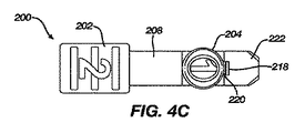
図4A〜図4Cはそれぞれ、機構のそれぞれ斜視図、側面図、及び頂面図を示している。図2及び図4A〜図4Cに示すように、インナーチューブ206が近位端部において機構200に取り付けられている。フリップアンカーケーブル400が配備されるとき、フリップアンカーケーブル400はインナーチューブ206の中へと挿入され、インナーチューブ206を通過する。更に、インナーチューブ206は、アウターチューブ300に嵌まり込み、アウターチューブ内でスライドする。この機構は、終端孔224を有する終端部分222を含み得る。終端孔224は、インナーチューブ206を機構200に取り付けるために、インナーチューブ206の近位端部を受容する。更に、終端孔224は終端部分222を通じて延びており、そのため、フリップアンカーケーブル400は終端孔224を通過して機構の他の部分と相互作用し得るようになっている。
4A-4C show respectively a perspective view, a side view and a top view of the mechanism. As shown in FIGS. 2 and 4A-4C, an
機構200はボタン支持部材208を含んでもよい。安全ボタン204はボタン支持部材208に連結されてもよい。また、スライダ202は、スライダ支持体232を介してボタン支持部材208に連結されてもよい。この機構の他の実施形態では、スライダは、スライダ支持体232を用いずに直接、ボタン支持部材208に連結されてもよい。
安全ボタン204はまた安全ボタン突出部220を含んでもよい。安全ボタン突出部220は、以下で更に詳細に説明するように、安全ボタンリテーナ218と係合してもよい。他の実施形態では、安全ボタン突出部220は代替的に、ボタン支持部材208から延びていてもよい。
The
機構200はまた中央支持部材210を含んでもよい。中央支持部材210は、一方の端部ではボタン支持部材208と連結し、もう一方の端部では終端部分222と連結してもよい。中央支持部材210とボタン支持部材208との間の連結は、機構200に力が加えられたときに中央支持部材210とボタン支持部材208が互いに対して移動し得るように可撓式であってもよい。
The
安全ボタンリテーナ218はまた、中央支持部材210に取り付けられてもよい。安全ボタン204がユーザによって押下されたとき、ボタン支持部材208は中央支持部材210に向かって屈曲し、それによって安全ボタン突出部220が安全ボタンリテーナ218と係合される。安全ボタン220と安全ボタンリテーナ218との間の係合により、安全ボタン204は定位置に、すなわち押下位置に固定されて、ボタン支持部材208が中央支持部材210から離れる方向に跳ね戻ることを防止する。安全ボタンリテーナ218及び安全ボタン突出部220の各形状が示されているが、安全ボタン204が押下された後にその安全ボタンをロックするのを支援する他の形状が用いられてもよい。
The
機構200はまた、終端部分222に可撓式に連結されたケーブル保持部材212を含んでもよい。他の実施形態では、ケーブル保持部材212はまた、中央支持部材210に連結されてもよい。ケーブル保持部材212は、中央支持部材210に向かって延びるケーブル保持突出部216を有してもよい。ケーブル保持突出部216は、ケーブル402の一部分と係合しその一部分を締め付けるために、ケーブル402が終端孔224から外に延びる場所の近くにあってもよい。ケーブル保持部材212はまた、ロッキング部材214に連結されてもよい。ロッキング部材214は、ケーブル保持部材212から離れる方向に延び、力が加えられたときにケーブル保持部材212に対して移動してもよい。ケーブル保持部材212、ケーブル保持突出部216、及びロッキング部材214の動作について、以下で更に詳細に説明することにする。様々な実施形態において、ケーブル保持部材212、ケーブル保持突出部216、及びロッキング部材214の形状及び配置は、以下で更に説明する機能性をもたらす限り、異なっていてもよい。
The
図4Cでは、安全ボタン204は、その表面に番号「1」を有するものとして示されている。同様に、スライダ202は、その表面に番号「2」を有するものとして示されている。これは挿入用具の操作においてユーザを案内するのを助けるためのものであり、その操作において、まず安全ボタン204が押下され、次いでスライダ202が前方にスライドされてフリップアンカーケーブル400の配備が開始され得る。
In FIG. 4C, the
図2はまた、挿入用具の外側にあるフリップアンカーケーブル400を示している。フリップアンカーケーブル400は、ケーブル402の遠位端部に取り付けられたフリップアンカー406を含んでもよい。ケーブルロッド404は、ケーブル402の近位端部に連結されている。フリップアンカー406は、フリップアンカーがケーブルに対して回転し得る柔軟な方式でケーブルに取り付けられてもよい。ある位置では、フリップアンカー406は、ケーブル402と整列され、例えばアウターチューブ300によって定位置に保たれてもよい。フリップアンカー406は、ケーブル402に対してある角度を自然になすようにケーブル402に連結されてもよく、そうすることで、フリップアンカー406がアウターチューブ300から解放されているときに、フリップアンカー406はケーブル402から離れて回転し、それによって配備され得る。
FIG. 2 also shows a
機構200は、単一の材料から単一のユニットとして作製されてもよい。その材料は、説明した機能性を達成するために必要な強度と柔軟性を有し得る。機構200は、低コストの材料及び製造プロセスを用いて作製され得る。これにより、フリップアンカーケーブルシステムのコストを低く維持しながら、使い捨て挿入用具100が使用可能となる。
図3は、組み立てられた挿入用具の内部を示すために第2のハンドル部材が取り外された、組み立てられた挿入用具を示している。インナーチューブ206がアウターチューブ300の内側に位置し、安全ボタン204が開口部110(図3には示さず)内に位置するように、機構200がインナーチューブ206と共に導入される。フリップアンカーケーブル400も導入される。ケーブルロッド404は、ケーブルロッド支持体112内で静止する。ケーブル402の一部分はケーブルロッド404から延び、次いで終端孔224(図3には示さず)に進入する。ケーブル402のこの部分は、図示のように折り曲げられ、ケーブルステー124によって定位置に保持される。ケーブルのこの部分は、ケーブルガイド114の下側部分の全体にわたるように折り曲げられてもよい。次いでケーブル402の別の部分がインナーチューブ206を通じて更に延び、そのため、フリップアンカー406はアウターチューブ300の端部に固定される。
FIG. 3 shows the assembled insertion tool with the second handle member removed to show the interior of the assembled insertion tool. The
ケーブル保持部材212はケーブル保持ストッパー116によって上向きに付勢され、そのため、ケーブル保持突出部216はケーブル402と接触し、それによってケーブル402を定位置に締め付ける。この締付けにより、ケーブル402が定位置に固定されてフリップアンカー406が定位置に維持され、ケーブルが誤って挿入用具100から引き出されることが防止される。
The
図6は、インナーチューブ及びアウターチューブから延びるフリップアンカーケーブルの端部にあるフリップアンカーを示している。フリップアンカー406は、近位端部408と遠位端部412とを有してもよい。フリップアンカー406はケーブル402の遠位端部に固定されてもよく、またフリップアンカー406はケーブル402から離れる方向に回転可能であってもよい。フリップアンカー406の近位端部408は、インナーチューブ206の端部の形状に対して相補的である形状を有してもよい。例えば、インナーチューブ206は、インナーチューブ206から延びるインナーチューブ終端部材226を有してもよい。このインナーチューブ終端部材226は、ケーブル402のうちの、フリップアンカー406の近位端部408とは反対側の部分に沿って延びている。更に、インナーチューブ206の端部に、フリップアンカー406の近位端部408を補完するインナーチューブプッシング面228がある。ユーザがスライダ202(図示せず)を前方に押し進めるとき、インナーチューブプッシング面228はフリップアンカー406を押し進め、アウターチューブ300から解放し、それによってフリップアンカー406が配備し得るようになる。
FIG. 6 shows a flip anchor at the end of the flip anchor cable extending from the inner and outer tubes. The
フリップアンカー406はまた、近位端部408に隣接するショルダー410を含んでもよい。近位端部408はインナーチューブ206と同等の直径を有してもよく、そのため、近位端部408はアウターチューブ300の端部の内側でロックされ得る。ショルダーは、近位端部408よりも大きな直径を有しており、その結果としてアウターチューブ300の端部と嵌合する。
The
挿入用具100の動作についてこれから説明することにする。ユーザが孔を、例えば、骨に穿孔した後、挿入用具100の端部は、挿入用具の遠位端部が骨の孔を完全に通過するまで、孔内に配置される。挿入用具100は、その長軸を中心として特定の角度位置へと回転されてもよく、それによってフリップアンカー406は所望の位置を有するようになる。ハンドル102上の方向マーカー230は、この整列を案内するのを支援する。
The operation of the
安全ボタン204は、安全ボタン開口部110内に存在し、これによって機構200は前方に移動することを防止される。次に、ユーザは安全ボタン204を押下して、安全ボタン突出部220を安全ボタンリテーナ218と係合させる。これにより、安全ボタン204は押下位置に固定され、また安全ボタン204は安全ボタン開口部から係合解除される。これで、ユーザは前方への力をスライダ202に加えて、機構200を前方にスライドさせ得るようになる。
The
機構200を前方にスライドさせることは、多数の様々な効果を伴う。第一に、ケーブル保持部材212が前方に移動すると、ケーブル保持部材212はケーブル保持ストッパー116から係合解除される。この結果、ケーブル保持突出部216はケーブル402への締付け力を減少させ、それによってフリップアンカーケーブル400を挿入用具100から引き出すことが可能となる。
Sliding the
第二に、ロッキング部材214が前方に移動すると、ロッキング部材214は使い捨てストッパー118の上を通過し、下向きに屈曲する。これにより、フリップアンカー406が配備されたことを示す、弾けるような音が生じ得る。更に、ロッキング部材214が下向きに、使い捨てストッパー118の上を移動すると、使い捨てストッパー118はこれで、ロッキング部材214が後方に移動するのを阻止するようになる。これにより、機構200が後方に移動することが防止され、挿入用具100のための使い捨ての安全機構が設けられる。
Second, as the locking
代替的な実施形態では、機構200はロッキング部材214を有さなくてもよく、またケーブル保持部材212が下向きに移動し、ケーブル保持ストッパー116から係合解除されると、ケーブル保持ストッパー116はこれで、ケーブル保持部材212が後方に移動するのを阻止し得るようになる。これにより、機構200が後方に移動することが防止され、挿入用具100のための使い捨ての安全機構が設けられる。
In an alternative embodiment, the
第三に、機構200が前方に移動するとき、インナーチューブ206は前方に移動してフリップアンカー406の近位端部408をアウターチューブ300の端部の外に押し出す。これにより、フリップアンカー406がロック解除される。フリップアンカー406は次いで回転し、それによって孔の周りの骨と係合し得る。
Third, as the
ユーザは次いで、挿入用具100を後方に引き、ケーブル402及びケーブルロッド404を挿入用具から引き出し得る。ケーブルガイド114は、ケーブル402が挿入用具100から引き出されるときにケーブル402が広がるのを容易にする。
The user may then pull the
フリップアンカーケーブル400が挿入用具100から完全に引き出されると、挿入用具100は処分され得る。これで、ユーザは、当該技術分野で知られているように、ケーブルを更に操作及び固定し得るようになる。
Once the
機構200及び挿入用具100は、安全ボタン204を1回押下することで、挿入用具100の状態に関する明確なフィードバックをユーザに与えることを可能にしている。安全ボタン204及びスライダ202は、挿入用具100の頂部で互いに近接しており、左利きのユーザにも右利きのユーザにも使いやすさをもたらしている。
The
機構200は、挿入用具100の安全な動作を提供する。安全ボタン204が押下されていない限り、ケーブル402は、ケーブル402とケーブル保持突出部216との間の高度な締付け力で機構200によって保持される。安全ボタン204を押下し、スライディングボタン202を遠位方向にスライドさせた後、ケーブル402にかかる締付け力は低下する。更に、安全ボタン204が押下され、機構200が前方にスライドされた後、機構200は、機構200が後方にスライドするのを防止する機構を有する。
挿入用具100の設計は、片手を用いた操作を容易にするものである。他のシステムは、正しく操作するために両手を必要とする。ユーザは多くの場合、複数の器具を同時に使用することを必要とするため、このことは問題となり得る。本明細書で記述された挿入用具は、ユーザが片手で首尾よくフリップアンカーケーブルを挿入し、機構をロック解除し、ケーブルを解放し、挿入用具を取り除くことを可能にする。
The design of the
挿入用具は事前に組み立てられ、ケーブルを内部に格納しているため、ケーブルの汚染又は誤操作が防止され得る。このことは、ケーブルが骨内に挿入され、フリップアンカーが解放されるまで、ユーザがケーブルに直接触れないことを意味する。これにより、リスクが最小化され、操作時間が短縮され、ユーザによる誤りが生じる可能性が低減される。 The insertion tool is preassembled and the cables are stored internally, so that contamination or misoperation of the cables can be prevented. This means that the user does not touch the cable directly until the cable is inserted into the bone and the flip anchor is released. This minimizes risk, reduces operating time and reduces the possibility of user error.
当業者ならば、本明細書中のいかなる図表又は概略図も、本発明の原理を具体化する例示的な構造の概念的な図面を代表しているにすぎないことを理解されたい。 It should be understood by those skilled in the art that any diagrams or diagrams herein are merely representative of conceptual drawings of exemplary structures embodying the principles of the present invention.
様々な例示の実施形態が、特にそれらの特定の例示の態様を参照しながら詳細に説明されてきたが、本発明は、他の実施形態も可能であり、またその詳細については、種々の明白な点において修正が可能であることを理解されたい。当業者にはすでに明らかなように、本発明の趣旨及び範囲内に留めながら変形及び修正を実施することが可能である。更に、様々な実施形態からの様々な構成要素は、本発明の趣旨及び範囲内にある他の実施形態を形成するように組み合わされることができる。したがって、前述の開示、説明、及び図面は、単に例示的な目的のみのためであって、本発明を何ら限定するものではなく、本発明は、特許請求の範囲によってのみ定義される。 While various illustrative embodiments have been described in detail with particular reference to certain illustrative aspects thereof, the present invention is capable of other embodiments, and as to the details thereof, various obvious aspects will be apparent. It should be understood that corrections can be made in It will be apparent to those skilled in the art that variations and modifications can be made while remaining within the spirit and scope of the invention. Further, various components from various embodiments can be combined to form other embodiments within the spirit and scope of the present invention. Accordingly, the foregoing disclosure, description, and figures are for illustrative purposes only, and are not intended to limit the present invention in any way, and the present invention is defined only by the claims.
〔実施の態様〕
(1) フリップアンカーケーブルを配備するための挿入用具であって、
安全ボタンとスライダとを有する機構であって、前記機構が第1の位置にあるときに、前記フリップアンカーケーブルの一部分に締付け力を加えるように構成されている、機構と、
前記機構に連結された近位端部を有するインナーチューブであって、前記フリップアンカーケーブルの第2の部分を収容するように構成されている、インナーチューブと、
安全ボタン開口部とスライダ開口部とを含んだハンドルであって、前記機構の一部分を囲むように構成されている、ハンドルと、
前記ハンドルに連結された近位端部を有するアウターチューブであって、前記インナーチューブを受容するように構成されている、アウターチューブと、を備え、
前記機構は、前記機構が第2の位置にあるときに前記フリップアンカーケーブルにかかる前記締付け力を低下させるように、また前記第2の位置において前記フリップアンカーケーブルのフリップアンカーを配備するように構成されている、挿入用具。
(2) 前記機構は、
安全ボタン突出部と、
前記安全ボタンを押下位置に固定するために前記安全ボタンが押下されているときに、前記安全ボタン突出部と係合するように構成された安全ボタンリテーナと、を更に備える、実施態様1に記載の挿入用具。
(3) 前記安全ボタンが前記押下位置にあることは、スライド力を前記スライダに加えることによって前記機構を前記第2の位置に配置することを可能にする、実施態様2に記載の挿入用具。
(4) 前記機構は、
ケーブル保持部材と、
前記ケーブル保持部材に連結されたケーブル保持突出部であって、前記第1の位置において前記フリップアンカーケーブルに前記締付け力を加えるように構成されている、ケーブル保持突出部と、を更に備える、実施態様1に記載の挿入用具。
(5) 前記ハンドルは、前記ケーブル保持部材と係合して前記第1の位置において前記フリップアンカーケーブルに前記締付け力を加えるように構成されたケーブル保持ストッパーを更に備える、実施態様4に記載の挿入用具。
[Aspect of embodiment]
(1) an insertion tool for deploying a flip anchor cable,
A mechanism having a safety button and a slider, wherein the mechanism is configured to apply a clamping force to a portion of the flip anchor cable when the mechanism is in the first position;
An inner tube having a proximal end coupled to the mechanism, the inner tube being configured to receive a second portion of the flip anchor cable;
A handle including a safety button opening and a slider opening, wherein the handle is configured to surround a portion of the mechanism;
An outer tube having a proximal end coupled to the handle, the outer tube being configured to receive the inner tube;
The mechanism is configured to reduce the clamping force on the flip anchor cable when the mechanism is in the second position and to deploy the flip anchor of the flip anchor cable in the second position Being inserted tool.
(2) The mechanism
With safety button protrusion,
A safety button retainer as set forth in claim 1, further comprising: a safety button retainer configured to engage the safety button protrusion when the safety button is depressed to lock the safety button in the depressed position. Insertion tool.
3. The insert according to claim 2, wherein the safety button being in the depressed position allows the mechanism to be placed in the second position by applying a sliding force to the slider.
(4) The mechanism
A cable holding member,
A cable retention protrusion coupled to the cable retention member, the cable retention protrusion being configured to apply the clamping force to the flip anchor cable at the first position. The insertion tool according to aspect 1.
The handle according to claim 4, further comprising a cable retention stopper configured to engage with the cable retention member to apply the clamping force to the flip anchor cable in the first position. Insertion tool.
(6) 前記ケーブル保持部材は、前記第2の位置において前記ケーブル保持ストッパーと係合して、前記機構が前記第1の位置に復帰することを防止するように構成されている、実施態様5に記載の挿入用具。
(7) 前記機構は、
ケーブル保持部材と、
前記ケーブル保持部材に連結されたロッキング部材と、を更に備え、
前記ハンドルは、前記第2の位置において前記ロッキング部材と係合して、前記機構が前記第1の位置に復帰することを防止するように構成された使い捨てストッパーを更に備える、実施態様1に記載の挿入用具。
(8) 前記ロッキング部材は、スライド力が前記スライダに加えられた際に前記機構が前記第1の位置から前記第2の位置へとスライドするとき、前記ロッキング部材が前記使い捨てストッパーの上方でスライドすると音を発生させるように構成されている、実施態様7に記載の挿入用具。
(9) 前記ハンドルは前記ハンドルの外部に方向インジケータを含む、実施態様1に記載の挿入用具。
(10) 前記ハンドルは、前記ハンドル内部の前記フリップアンカーケーブルを固定するように構成された複数のケーブルステーを含む、実施態様1に記載の挿入用具。
The cable holding member is configured to engage with the cable holding stopper at the second position to prevent the mechanism from returning to the first position. Insertion tool as described in.
(7) The mechanism is
A cable holding member,
A locking member connected to the cable holding member;
The handle according to claim 1, further comprising a disposable stopper configured to engage with the locking member in the second position to prevent the mechanism from returning to the first position. Insertion tool.
(8) The locking member slides above the disposable stopper when the mechanism slides from the first position to the second position when a sliding force is applied to the slider. The insertion tool according to claim 7, wherein the insertion tool is configured to generate a sound.
The insert according to claim 1, wherein the handle includes a direction indicator on the outside of the handle.
The insertion tool of claim 1, wherein the handle includes a plurality of cable stays configured to secure the flip anchor cable within the handle.
(11) 前記ハンドルは、前記ハンドル内部の前記フリップアンカーケーブルを展開するのを容易にするように構成された複数のケーブルガイドを含む、実施態様1に記載の挿入用具。
(12) 前記ハンドルは、前記ハンドル内部の前記フリップアンカーケーブルの前記ケーブルロッドを固定するように構成されたケーブルロッド支持体を含む、実施態様1に記載の挿入用具。
(13) 前記アウターチューブの遠位端部は、前記フリップアンカーの近位端部を受容して前記フリップアンカーを固定するように構成されている、実施態様1に記載の挿入用具。
(14) 前記インナーチューブは、前記フリップアンカーの前記近位端部と係合するように構成され、かつスライド力が前記スライダに加えられた際に前記機構が前記第1の位置から前記第2の位置にスライドするときに前記アウターチューブの前記遠位端部から前記フリップアンカーの前記近位端部を押し出すように構成された遠位端部を有する、実施態様13に記載の挿入用具。
(15) 前記機構は、
前記安全ボタン及び前記スライダに連結されたボタン支持部材と、
前記ボタン支持部材に柔軟に連結された中央支持部材と、
前記中央支持部材に柔軟に連結されたケーブル保持部材と、を更に備える、実施態様1に記載の挿入用具。
The insertion tool of claim 1, wherein the handle includes a plurality of cable guides configured to facilitate deployment of the flip anchor cable within the handle.
The insertion tool according to claim 1, wherein the handle includes a cable rod support configured to secure the cable rod of the flip anchor cable inside the handle.
The insertion tool according to claim 1, wherein a distal end of the outer tube is configured to receive a proximal end of the flip anchor to secure the flip anchor.
(14) The inner tube is configured to engage with the proximal end of the flip anchor, and the mechanism is configured to move from the first position to the second position when a sliding force is applied to the slider. The insertion tool according to claim 13, comprising a distal end configured to push the proximal end of the flip anchor from the distal end of the outer tube when sliding into the position of.
(15) The mechanism is
A button support member connected to the safety button and the slider;
A central support member flexibly connected to the button support member;
The insertion tool of claim 1, further comprising a cable retention member flexibly coupled to the central support member.
(16) 前記機構は、
安全ボタン突出部と、
前記中央支持部材に連結された安全ボタンリテーナであって、前記安全ボタンを押下位置に固定するために前記安全ボタンが押下されているときに前記安全ボタン突出部と係合するように構成された、安全ボタンリテーナと、
前記ケーブル保持部材に連結されたケーブル保持突出部であって、前記第1の位置において前記フリップアンカーケーブルに前記締付け力を加えるように構成されている、ケーブル保持突出部と、
前記ケーブル保持部材に連結されたロッキング部材と、を更に備える、実施態様15に記載の挿入用具。
(17) 前記ハウジングは、前記ケーブルの第3の部分及び前記ケーブルの前記第3の部分に取り付けられたケーブルロッドを囲むように構成されている、実施態様1に記載の挿入用具。
(18) 挿入用具であって、
フリップアンカーとケーブルロッドとケーブルとを含んだフリップアンカーケーブルであって、該ケーブルは、遠位端部において前記フリップアンカーに連結され、近位端部において前記ケーブルロッドに連結されている、フリップアンカーケーブルと、
安全ボタンとスライダとを有する機構であって、前記機構が第1の位置にあるときに、前記フリップアンカーケーブルの第1の部分に締付け力を加えるように構成されている、機構と、
前記機構に連結された近位端部を有するインナーチューブであって、前記フリップアンカーケーブルの第2の部分を収容するように構成されている、インナーチューブと、
安全ボタン開口部とスライダ開口部とを含んだハンドルであって、前記機構の一部分を囲むように構成されている、ハンドルと、
前記ハンドルに連結された近位端部を有するアウターチューブであって、前記インナーチューブを受容するように構成されている、アウターチューブと、を備え、
前記機構は、前記機構が第2の位置にあるときに前記フリップアンカーケーブルにかかる前記締付け力を低下させるように、また前記第2の位置において前記フリップアンカーケーブルのフリップアンカーを配備するように構成されている、挿入用具。
(19) 前記フリップアンカーは、前記フリップアンカーを固定するために前記アウターチューブの遠位端部内部にある近位端部を含む、実施態様18に記載の挿入用具。
(20) 前記フリップアンカーは前記近位端部に隣接するショルダーを含み、前記ショルダーは、前記インナーチューブの遠位端部と係合するように構成されており、前記インナーチューブの前記遠位端部は、スライド力が前記スライダに加えられた際に前記機構が前記第1の位置から前記第2の位置にスライドするときに、前記ショルダーを押し進めて前記フリップアンカーを前記アウターチューブの前記遠位端部から外に移動させる、実施態様19に記載の挿入用具。
(16) The mechanism is
With safety button protrusion,
A safety button retainer coupled to the central support member, configured to engage the safety button protrusion when the safety button is depressed to lock the safety button in the depressed position. , Safety button retainer,
A cable retention protrusion coupled to the cable retention member, wherein the cable retention protrusion is configured to apply the clamping force to the flip anchor cable at the first position;
The insertion tool according to claim 15, further comprising a locking member coupled to the cable holding member.
The insertion tool according to claim 1, wherein the housing is configured to surround a third portion of the cable and a cable rod attached to the third portion of the cable.
(18) an insertion tool,
A flip anchor cable comprising a flip anchor, a cable rod and a cable, said cable being connected to said flip anchor at its distal end and connected to said cable rod at its proximal end. Cable,
A mechanism having a safety button and a slider, wherein the mechanism is configured to apply a clamping force to the first portion of the flip anchor cable when the mechanism is in the first position;
An inner tube having a proximal end coupled to the mechanism, the inner tube being configured to receive a second portion of the flip anchor cable;
A handle including a safety button opening and a slider opening, wherein the handle is configured to surround a portion of the mechanism;
An outer tube having a proximal end coupled to the handle, the outer tube being configured to receive the inner tube;
The mechanism is configured to reduce the clamping force on the flip anchor cable when the mechanism is in the second position and to deploy the flip anchor of the flip anchor cable in the second position Being inserted tool.
(19) The insertion tool according to embodiment 18, wherein the flip anchor includes a proximal end that is inside the distal end of the outer tube to secure the flip anchor.
(20) The flip anchor includes a shoulder adjacent to the proximal end, the shoulder being configured to engage a distal end of the inner tube, the distal end of the inner tube A portion for pushing the shoulder to move the flip anchor to the distal end of the outer tube as the mechanism slides from the first position to the second position when a sliding force is applied to the slider. 20. An insert according to embodiment 19, moved out of the end.
(21) 前記フリップアンカーは、前記インナーチューブの前記遠位端部が前記ショルダーを押し進めて前記フリップアンカーを前記遠位端部から外に移動させるときに、前記フリップアンカーの前記近位端部が前記ケーブルから離れて回転することによって配備される、実施態様20に記載の挿入用具。
(22) 前記ハウジングは、前記ケーブルの第3の部分及び前記ケーブルロッドを囲むように構成されている、実施態様18に記載の挿入用具。
(23) フリップアンカーケーブルを配備するための挿入用具のための機構であって、
安全ボタンと、
スライダと、
前記安全ボタン及び前記スライダに連結されたボタン支持部材と、
前記ボタン支持部材に柔軟に連結された中央支持部材と、
前記中央支持部材に柔軟に連結されたケーブル保持部材であって、
前記機構が第1の位置にあるときに前記フリップアンカーケーブルの一部分に締付け力を加え、
前記機構が第2の位置にあるときに前記フリップアンカーケーブルへの前記締付け力を低減するように構成された、ケーブル保持部材と、を備える機構。
(24) 安全ボタン突出部と、
前記安全ボタンを押下位置に固定するために前記安全ボタンが押下されているときに、前記安全ボタン突出部と係合するように構成された安全ボタンリテーナと、を更に備える、実施態様23に記載の機構。
(25) 前記安全ボタンが前記押下位置にあることは、スライド力を前記スライダに加えることによって前記機構を前記第2の位置に配置することを可能にする、実施態様24に記載の機構。
(21) The flip anchor includes the proximal end of the flip anchor as the distal end of the inner tube pushes the shoulder to move the flip anchor out of the distal end. 21. An insertion device according to embodiment 20, which is deployed by rotating away from the cable.
The insertion tool of claim 18, wherein the housing is configured to surround a third portion of the cable and the cable rod.
(23) A mechanism for an insertion tool for deploying a flip anchor cable,
With safety button
With the slider,
A button support member connected to the safety button and the slider;
A central support member flexibly connected to the button support member;
A cable holding member flexibly connected to the central support member, wherein
Apply a clamping force to a portion of the flip anchor cable when the mechanism is in the first position;
A cable retention member configured to reduce the clamping force on the flip anchor cable when the mechanism is in the second position.
(24) Safety button projection,
24. The safety button of claim 23, further comprising: a safety button retainer configured to engage the safety button protrusion when the safety button is pressed to lock the safety button in the depressed position. Mechanism.
25. The mechanism according to embodiment 24, wherein the safety button being in the depressed position enables placing the mechanism in the second position by applying a sliding force to the slider.
(26) 前記ケーブル保持部材は、前記ケーブル保持部材に連結されたケーブル保持突出部を更に備え、前記ケーブル保持突出部は、前記第1の位置において前記フリップアンカーケーブルに前記締付け力を加えるように構成されている、実施態様23に記載の機構。
(27) 前記機構は、前記挿入用具のハンドル上の使い捨てストッパーと係合するように構成された前記ケーブル保持部材に連結されたロッキング部材を更に備え、前記ロッキング部材は、前記機構が前記第1の位置に復帰するのを防止するために、前記第2の位置において前記使い捨てストッパーと係合するように構成されている、実施態様23に記載の挿入用具。
(26) The cable holding member further comprises a cable holding protrusion connected to the cable holding member, wherein the cable holding protrusion applies the tightening force to the flip anchor cable at the first position. 24. The mechanism according to embodiment 23, which is configured.
(27) The mechanism further includes a locking member coupled to the cable holding member configured to engage with a disposable stopper on the handle of the insertion tool, the locking member being the first member of the first mechanism. 24. An insert according to claim 23, configured to engage with the disposable stopper in the second position to prevent return to the position.
Claims (27)
安全ボタンとスライダとを有する機構であって、前記機構が第1の位置にあるときに、前記フリップアンカーケーブルの一部分に締付け力を加えるように構成されている、機構と、
前記機構に連結された近位端部を有するインナーチューブであって、前記フリップアンカーケーブルの第2の部分を収容するように構成されている、インナーチューブと、
安全ボタン開口部とスライダ開口部とを含んだハンドルであって、前記機構の一部分を囲むように構成されている、ハンドルと、
前記ハンドルに連結された近位端部を有するアウターチューブであって、前記インナーチューブを受容するように構成されている、アウターチューブと、を備え、
前記機構は、前記機構が第2の位置にあるときに前記フリップアンカーケーブルにかかる前記締付け力を低下させるように、また前記第2の位置において前記フリップアンカーケーブルのフリップアンカーを配備するように構成されている、挿入用具。 An insertion tool for deploying a flip anchor cable,
A mechanism having a safety button and a slider, wherein the mechanism is configured to apply a clamping force to a portion of the flip anchor cable when the mechanism is in the first position;
An inner tube having a proximal end coupled to the mechanism, the inner tube being configured to receive a second portion of the flip anchor cable;
A handle including a safety button opening and a slider opening, wherein the handle is configured to surround a portion of the mechanism;
An outer tube having a proximal end coupled to the handle, the outer tube being configured to receive the inner tube;
The mechanism is configured to reduce the clamping force on the flip anchor cable when the mechanism is in the second position and to deploy the flip anchor of the flip anchor cable in the second position Being inserted tool.
安全ボタン突出部と、
前記安全ボタンを押下位置に固定するために前記安全ボタンが押下されているときに、前記安全ボタン突出部と係合するように構成された安全ボタンリテーナと、を更に備える、請求項1に記載の挿入用具。 The mechanism is
With safety button protrusion,
The safety button retainer as recited in claim 1, further comprising: a safety button retainer configured to engage the safety button protrusion when the safety button is depressed to lock the safety button in the depressed position. Insertion tool.
ケーブル保持部材と、
前記ケーブル保持部材に連結されたケーブル保持突出部であって、前記第1の位置において前記フリップアンカーケーブルに前記締付け力を加えるように構成されている、ケーブル保持突出部と、を更に備える、請求項1に記載の挿入用具。 The mechanism is
A cable holding member,
The cable retention protrusion coupled to the cable retention member, the cable retention protrusion being configured to apply the clamping force to the flip anchor cable at the first position. The insertion tool according to Item 1.
ケーブル保持部材と、
前記ケーブル保持部材に連結されたロッキング部材と、を更に備え、
前記ハンドルは、前記第2の位置において前記ロッキング部材と係合して、前記機構が前記第1の位置に復帰することを防止するように構成された使い捨てストッパーを更に備える、請求項1に記載の挿入用具。 The mechanism is
A cable holding member,
A locking member connected to the cable holding member;
The handle of claim 1, further comprising a disposable stopper configured to engage the locking member in the second position to prevent the mechanism from returning to the first position. Insertion tool.
前記安全ボタン及び前記スライダに連結されたボタン支持部材と、
前記ボタン支持部材に柔軟に連結された中央支持部材と、
前記中央支持部材に柔軟に連結されたケーブル保持部材と、を更に備える、請求項1に記載の挿入用具。 The mechanism is
A button support member connected to the safety button and the slider;
A central support member flexibly connected to the button support member;
The insertion tool according to claim 1, further comprising: a cable holding member flexibly connected to the central support member.
安全ボタン突出部と、
前記中央支持部材に連結された安全ボタンリテーナであって、前記安全ボタンを押下位置に固定するために前記安全ボタンが押下されているときに前記安全ボタン突出部と係合するように構成された、安全ボタンリテーナと、
前記ケーブル保持部材に連結されたケーブル保持突出部であって、前記第1の位置において前記フリップアンカーケーブルに前記締付け力を加えるように構成されている、ケーブル保持突出部と、
前記ケーブル保持部材に連結されたロッキング部材と、を更に備える、請求項15に記載の挿入用具。 The mechanism is
With safety button protrusion,
A safety button retainer coupled to the central support member, configured to engage the safety button protrusion when the safety button is depressed to lock the safety button in the depressed position. , Safety button retainer,
A cable retention protrusion coupled to the cable retention member, wherein the cable retention protrusion is configured to apply the clamping force to the flip anchor cable at the first position;
The insertion tool according to claim 15, further comprising: a locking member coupled to the cable holding member.
フリップアンカーとケーブルロッドとケーブルとを含んだフリップアンカーケーブルであって、該ケーブルは、遠位端部において前記フリップアンカーに連結され、近位端部において前記ケーブルロッドに連結されている、フリップアンカーケーブルと、
安全ボタンとスライダとを有する機構であって、前記機構が第1の位置にあるときに、前記フリップアンカーケーブルの第1の部分に締付け力を加えるように構成されている、機構と、
前記機構に連結された近位端部を有するインナーチューブであって、前記フリップアンカーケーブルの第2の部分を収容するように構成されている、インナーチューブと、
安全ボタン開口部とスライダ開口部とを含んだハンドルであって、前記機構の一部分を囲むように構成されている、ハンドルと、
前記ハンドルに連結された近位端部を有するアウターチューブであって、前記インナーチューブを受容するように構成されている、アウターチューブと、を備え、
前記機構は、前記機構が第2の位置にあるときに前記フリップアンカーケーブルにかかる前記締付け力を低下させるように、また前記第2の位置において前記フリップアンカーケーブルのフリップアンカーを配備するように構成されている、挿入用具。 An insertion tool,
A flip anchor cable comprising a flip anchor, a cable rod and a cable, said cable being connected to said flip anchor at its distal end and connected to said cable rod at its proximal end. Cable,
A mechanism having a safety button and a slider, wherein the mechanism is configured to apply a clamping force to the first portion of the flip anchor cable when the mechanism is in the first position;
An inner tube having a proximal end coupled to the mechanism, the inner tube being configured to receive a second portion of the flip anchor cable;
A handle including a safety button opening and a slider opening, wherein the handle is configured to surround a portion of the mechanism;
An outer tube having a proximal end coupled to the handle, the outer tube being configured to receive the inner tube;
The mechanism is configured to reduce the clamping force on the flip anchor cable when the mechanism is in the second position and to deploy the flip anchor of the flip anchor cable in the second position Being inserted tool.
安全ボタンと、
スライダと、
前記安全ボタン及び前記スライダに連結されたボタン支持部材と、
前記ボタン支持部材に柔軟に連結された中央支持部材と、
前記中央支持部材に柔軟に連結されたケーブル保持部材であって、
前記機構が第1の位置にあるときに前記フリップアンカーケーブルの一部分に締付け力を加え、
前記機構が第2の位置にあるときに前記フリップアンカーケーブルへの前記締付け力を低減するように構成された、ケーブル保持部材と、を備える機構。 A mechanism for an insertion tool for deploying a flip anchor cable,
With safety button
With the slider,
A button support member connected to the safety button and the slider;
A central support member flexibly connected to the button support member;
A cable holding member flexibly connected to the central support member, wherein
Apply a clamping force to a portion of the flip anchor cable when the mechanism is in the first position;
A cable retention member configured to reduce the clamping force on the flip anchor cable when the mechanism is in the second position.
前記安全ボタンを押下位置に固定するために前記安全ボタンが押下されているときに、前記安全ボタン突出部と係合するように構成された安全ボタンリテーナと、を更に備える、請求項23に記載の機構。 With safety button protrusion,
24. The safety button retainer of claim 23, further comprising: a safety button retainer configured to engage the safety button protrusion when the safety button is depressed to lock the safety button in the depressed position. Mechanism.
Applications Claiming Priority (3)
| Application Number | Priority Date | Filing Date | Title |
|---|---|---|---|
| US15/151,144 | 2016-05-10 | ||
| US15/151,144 US10238444B2 (en) | 2016-05-10 | 2016-05-10 | Insertion tool for flip anchor cable system insertion |
| PCT/US2017/031641 WO2017196769A1 (en) | 2016-05-10 | 2017-05-09 | Insertion tool for flip anchor cable system insertion |
Publications (2)
| Publication Number | Publication Date |
|---|---|
| JP2019516466A true JP2019516466A (en) | 2019-06-20 |
| JP2019516466A5 JP2019516466A5 (en) | 2020-04-02 |
Family
ID=58710150
Family Applications (1)
| Application Number | Title | Priority Date | Filing Date |
|---|---|---|---|
| JP2018559293A Abandoned JP2019516466A (en) | 2016-05-10 | 2017-05-09 | Insertion tool for inserting a flip anchor cable system |
Country Status (8)
| Country | Link |
|---|---|
| US (2) | US10238444B2 (en) |
| EP (1) | EP3454766A1 (en) |
| JP (1) | JP2019516466A (en) |
| CN (1) | CN109152594A (en) |
| AU (1) | AU2017264602A1 (en) |
| BR (1) | BR112018072678A2 (en) |
| CA (1) | CA3023657A1 (en) |
| WO (1) | WO2017196769A1 (en) |
Families Citing this family (5)
| Publication number | Priority date | Publication date | Assignee | Title |
|---|---|---|---|---|
| US10105169B2 (en) | 2015-11-13 | 2018-10-23 | Leith Medical LLC | Bone fixation systems, apparatuses, and methods with anti-back-out feature |
| US11395687B2 (en) | 2019-03-01 | 2022-07-26 | DePuy Synthes Products, Inc. | Insertion tool for flip anchor cable system insertion |
| US11064995B2 (en) * | 2019-05-02 | 2021-07-20 | Arthrex, Inc. | Surgical device with trigger operated needle |
| CA3157935A1 (en) | 2019-10-14 | 2021-04-22 | Leith Medical, LLC | A bone fixation system with fasteners and a removal tool for decoupling of the fasteners |
| JP2022552325A (en) * | 2019-10-14 | 2022-12-15 | リース メディカル, エルエルシー | Devices for stabilization of fracture sites |
Family Cites Families (10)
| Publication number | Priority date | Publication date | Assignee | Title |
|---|---|---|---|---|
| US5662658A (en) | 1996-01-19 | 1997-09-02 | Mitek Surgical Products, Inc. | Bone anchor inserter, method for loading same, method for holding and delivering a bone anchor, and method for inserting a bone anchor in a bone |
| US5814051A (en) | 1997-06-06 | 1998-09-29 | Mitex Surgical Products, Inc. | Suture anchor insertion system |
| US5944724A (en) | 1997-10-30 | 1999-08-31 | Mitek Surgical Products, Inc. | Suture anchor insertion system |
| US6068648A (en) | 1998-01-26 | 2000-05-30 | Orthodyne, Inc. | Tissue anchoring system and method |
| US20020188301A1 (en) | 2001-06-11 | 2002-12-12 | Dallara Mark Douglas | Tissue anchor insertion system |
| US9173647B2 (en) | 2004-10-26 | 2015-11-03 | P Tech, Llc | Tissue fixation system |
| CN102292032A (en) * | 2008-11-26 | 2011-12-21 | 史密夫和内修有限公司 | Tissue repair device |
| US8523903B2 (en) * | 2009-10-30 | 2013-09-03 | Depuy Mitek, Llc | Partial thickness rotator cuff repair system and method |
| CN102958458B (en) * | 2010-06-29 | 2015-05-13 | 斯恩蒂斯有限公司 | Insertion instrument for anchor assembly |
| US8641717B2 (en) | 2010-07-01 | 2014-02-04 | DePuy Synthes Products, LLC | Guidewire insertion methods and devices |
-
2016
- 2016-05-10 US US15/151,144 patent/US10238444B2/en active Active
-
2017
- 2017-05-09 JP JP2018559293A patent/JP2019516466A/en not_active Abandoned
- 2017-05-09 EP EP17724245.0A patent/EP3454766A1/en not_active Withdrawn
- 2017-05-09 CN CN201780028971.9A patent/CN109152594A/en active Pending
- 2017-05-09 BR BR112018072678A patent/BR112018072678A2/en not_active Application Discontinuation
- 2017-05-09 CA CA3023657A patent/CA3023657A1/en not_active Abandoned
- 2017-05-09 AU AU2017264602A patent/AU2017264602A1/en not_active Abandoned
- 2017-05-09 WO PCT/US2017/031641 patent/WO2017196769A1/en unknown
-
2019
- 2019-01-30 US US16/262,079 patent/US11058470B2/en active Active
Also Published As
| Publication number | Publication date |
|---|---|
| EP3454766A1 (en) | 2019-03-20 |
| AU2017264602A1 (en) | 2018-11-15 |
| US20190159821A1 (en) | 2019-05-30 |
| CN109152594A (en) | 2019-01-04 |
| US11058470B2 (en) | 2021-07-13 |
| CA3023657A1 (en) | 2017-11-16 |
| WO2017196769A1 (en) | 2017-11-16 |
| US20170325867A1 (en) | 2017-11-16 |
| US10238444B2 (en) | 2019-03-26 |
| BR112018072678A2 (en) | 2019-02-19 |
Similar Documents
| Publication | Publication Date | Title |
|---|---|---|
| US11058470B2 (en) | Insertion tool for flip anchor cable system insertion | |
| EP2014241B1 (en) | Applicator for suture/button construct | |
| US11141147B2 (en) | Endoscopic suturing system having external instrument channel | |
| CN106999187B (en) | Treatment tool for endoscope | |
| EP3258868B1 (en) | Devices and systems for semi-rigid bone fixation | |
| JP6532867B2 (en) | Orthopedic anchor assembly | |
| KR20160141785A (en) | Deployment handle for a medical device deployment system | |
| JP2005253540A (en) | Rod fixing auxiliary device | |
| KR20010040394A (en) | Tissue anchoring system and method | |
| KR20110048523A (en) | Minimally Invasive Implants and Crimping Systems | |
| US10499972B2 (en) | Mini cable tensioner for orthopedic cable tensioning | |
| JP2011072772A (en) | Rod holder and minimally invasive spine surgery system using the same | |
| JP2007075613A (en) | Treatment appliance cartridge for biological tissue | |
| JP2013526926A (en) | Bone fixation system | |
| US20140276962A1 (en) | Extracting device for surgical fasteners | |
| US9956021B1 (en) | Tensioning and crimping tool for orthopedic cable tensioning | |
| WO2016154406A1 (en) | Bone anchor system having movable medial eyelet | |
| KR200484392Y1 (en) | Medical catheter | |
| US20210298759A1 (en) | Applicator, medical apparatus, and operation method of medical apparatus | |
| US11395688B2 (en) | Tool for crimping orthopedic cable | |
| KR101901516B1 (en) | Suture screw sheath and suturing device including the same | |
| US20200275920A1 (en) | Insertion tool for flip anchor cable system insertion | |
| US11529178B2 (en) | Targeting device for fixation of bone fragments at a bone fracture | |
| EP4076221A1 (en) | Surgical device for the surgical grafting of a bone-tendon-bone graft in a dislocated and /or sub-luxated joint | |
| IL191180A (en) | Extracting device for surgical fasteners |
Legal Events
| Date | Code | Title | Description |
|---|---|---|---|
| A521 | Request for written amendment filed |
Free format text: JAPANESE INTERMEDIATE CODE: A523 Effective date: 20200220 |
|
| A621 | Written request for application examination |
Free format text: JAPANESE INTERMEDIATE CODE: A621 Effective date: 20200220 |
|
| A762 | Written abandonment of application |
Free format text: JAPANESE INTERMEDIATE CODE: A762 Effective date: 20200518 |