JP2019510991A - Arrangement for rendering virtual reality with an adaptive focal plane - Google Patents
Arrangement for rendering virtual reality with an adaptive focal plane Download PDFInfo
- Publication number
- JP2019510991A JP2019510991A JP2018534138A JP2018534138A JP2019510991A JP 2019510991 A JP2019510991 A JP 2019510991A JP 2018534138 A JP2018534138 A JP 2018534138A JP 2018534138 A JP2018534138 A JP 2018534138A JP 2019510991 A JP2019510991 A JP 2019510991A
- Authority
- JP
- Japan
- Prior art keywords
- virtual reality
- processor
- field
- pixels
- image
- Prior art date
- Legal status (The legal status is an assumption and is not a legal conclusion. Google has not performed a legal analysis and makes no representation as to the accuracy of the status listed.)
- Pending
Links
- 230000003044 adaptive effect Effects 0.000 title description 37
- 238000009877 rendering Methods 0.000 title description 10
- 210000001747 pupil Anatomy 0.000 claims abstract description 32
- 238000000034 method Methods 0.000 claims description 48
- 239000002131 composite material Substances 0.000 claims description 36
- 230000000694 effects Effects 0.000 claims description 14
- 210000003128 head Anatomy 0.000 claims description 10
- 230000000007 visual effect Effects 0.000 claims description 6
- 230000004438 eyesight Effects 0.000 abstract description 2
- 230000010344 pupil dilation Effects 0.000 description 22
- 238000012545 processing Methods 0.000 description 11
- 238000004590 computer program Methods 0.000 description 8
- 239000011521 glass Substances 0.000 description 5
- 206010027646 Miosis Diseases 0.000 description 3
- 230000008602 contraction Effects 0.000 description 3
- 230000006978 adaptation Effects 0.000 description 2
- 238000010191 image analysis Methods 0.000 description 2
- 238000012986 modification Methods 0.000 description 2
- 230000004048 modification Effects 0.000 description 2
- XUIMIQQOPSSXEZ-UHFFFAOYSA-N Silicon Chemical compound [Si] XUIMIQQOPSSXEZ-UHFFFAOYSA-N 0.000 description 1
- 230000003190 augmentative effect Effects 0.000 description 1
- 230000005540 biological transmission Effects 0.000 description 1
- 238000011960 computer-aided design Methods 0.000 description 1
- 238000013500 data storage Methods 0.000 description 1
- 230000004886 head movement Effects 0.000 description 1
- 230000003287 optical effect Effects 0.000 description 1
- 230000005043 peripheral vision Effects 0.000 description 1
- 230000001953 sensory effect Effects 0.000 description 1
- 229910052710 silicon Inorganic materials 0.000 description 1
- 239000010703 silicon Substances 0.000 description 1
- 238000004088 simulation Methods 0.000 description 1
Images


Classifications
-
- G06T5/70—
-
- G—PHYSICS
- G02—OPTICS
- G02B—OPTICAL ELEMENTS, SYSTEMS OR APPARATUS
- G02B27/00—Optical systems or apparatus not provided for by any of the groups G02B1/00 - G02B26/00, G02B30/00
- G02B27/0075—Optical systems or apparatus not provided for by any of the groups G02B1/00 - G02B26/00, G02B30/00 with means for altering, e.g. increasing, the depth of field or depth of focus
-
- G—PHYSICS
- G02—OPTICS
- G02B—OPTICAL ELEMENTS, SYSTEMS OR APPARATUS
- G02B27/00—Optical systems or apparatus not provided for by any of the groups G02B1/00 - G02B26/00, G02B30/00
- G02B27/01—Head-up displays
- G02B27/017—Head mounted
-
- G—PHYSICS
- G06—COMPUTING; CALCULATING OR COUNTING
- G06V—IMAGE OR VIDEO RECOGNITION OR UNDERSTANDING
- G06V40/00—Recognition of biometric, human-related or animal-related patterns in image or video data
- G06V40/10—Human or animal bodies, e.g. vehicle occupants or pedestrians; Body parts, e.g. hands
- G06V40/18—Eye characteristics, e.g. of the iris
- G06V40/19—Sensors therefor
-
- H—ELECTRICITY
- H04—ELECTRIC COMMUNICATION TECHNIQUE
- H04N—PICTORIAL COMMUNICATION, e.g. TELEVISION
- H04N13/00—Stereoscopic video systems; Multi-view video systems; Details thereof
- H04N13/10—Processing, recording or transmission of stereoscopic or multi-view image signals
- H04N13/106—Processing image signals
- H04N13/122—Improving the 3D impression of stereoscopic images by modifying image signal contents, e.g. by filtering or adding monoscopic depth cues
-
- H—ELECTRICITY
- H04—ELECTRIC COMMUNICATION TECHNIQUE
- H04N—PICTORIAL COMMUNICATION, e.g. TELEVISION
- H04N13/00—Stereoscopic video systems; Multi-view video systems; Details thereof
- H04N13/30—Image reproducers
- H04N13/332—Displays for viewing with the aid of special glasses or head-mounted displays [HMD]
- H04N13/344—Displays for viewing with the aid of special glasses or head-mounted displays [HMD] with head-mounted left-right displays
-
- H—ELECTRICITY
- H04—ELECTRIC COMMUNICATION TECHNIQUE
- H04N—PICTORIAL COMMUNICATION, e.g. TELEVISION
- H04N13/00—Stereoscopic video systems; Multi-view video systems; Details thereof
- H04N13/30—Image reproducers
- H04N13/366—Image reproducers using viewer tracking
- H04N13/383—Image reproducers using viewer tracking for tracking with gaze detection, i.e. detecting the lines of sight of the viewer's eyes
-
- G—PHYSICS
- G06—COMPUTING; CALCULATING OR COUNTING
- G06T—IMAGE DATA PROCESSING OR GENERATION, IN GENERAL
- G06T2207/00—Indexing scheme for image analysis or image enhancement
- G06T2207/10—Image acquisition modality
- G06T2207/10004—Still image; Photographic image
- G06T2207/10012—Stereo images
Abstract
仮想現実装置は仮想現実表示スクリーンを含む。更に、仮想現実装置は、仮想現実表示において注目のオブジェクトを決定するようユーザの1つ以上の目の注視方向を追跡する視標追跡システムを含む。その上、仮想現実装置はプロセッサを含む。仮想現実装置は、プロセッサによって実行される場合に、仮想現実装置に、仮想現実表示によって表示されている仮想現実イメージの輝度に基づき1つ以上の目の1つ以上の瞳孔寸法を推定させる命令の組を有するメモリを更に含む。仮想現実装置は、更に、推定された1つ以上の瞳孔寸法に基づき焦点面を決定させられる。The virtual reality device includes a virtual reality display screen. In addition, the virtual reality device includes a vision tracking system that tracks the gaze direction of the user's eyes to determine the object of interest in the virtual reality display. Additionally, the virtual reality device includes a processor. The virtual reality device, when executed by the processor, instructs the virtual reality device to estimate one or more pupil sizes of one or more eyes based on the brightness of the virtual reality image being displayed by the virtual reality display. It further includes a memory having a set. The virtual reality system is further caused to determine the focal plane based on the estimated one or more pupil sizes.
Description
本開示は、コンピューティング・システムの分野に概して関係がある。より具体的には、本開示は仮想現実システムに関係がある。 The present disclosure is generally related to the field of computing systems. More specifically, the present disclosure relates to virtual reality systems.
仮想現実(“VR”)(virtual reality)システムは、現実世界環境におけるユーザの現実の所在をシミュレートする。シミュレーションは、様々な感覚的経験、例えば、視界、音響、触覚、におい、などをユーザに与えることによって、人工的に生成される。 Virtual reality ("VR") systems simulate the real-life location of a user in a real-world environment. The simulation is artificially generated by providing the user with various sensory experiences, such as visibility, sound, touch, smell, etc.
いくつかの現在のVRシステムは、立体表示デバイスを介して実施されている。立体表示デバイスは、立体視、すなわち、第1の画像をユーザの第1の目に、第2の画像をユーザの第2の目に提示して、2D画像から3D画像を人工的に生成すること、を介して、画像における奥行きの錯覚を提供する。 Some current VR systems are implemented via stereoscopic display devices. The stereoscopic display device presents a stereoscopic view, ie, artificially generating a 3D image from a 2D image, presenting the first image to the first eye of the user and the second image to the second eye of the user Provides an illusion of depth in the image.
VRメガネは、立体視を利用するVRシステムの一例である。例えば、VRメガネは、ユーザの両目の直接的な周辺視野をカバーするヘッドマウント型表示スクリーンを通常は含む。VRメガネは、同じ3Dシーンの2つの画像を表示する。次いで、それら2つの画像は、3Dシーンを現実的な方法でレンダリングする対応する量のパララックスを伴ってコンピュータ・グラフィクス・システムによって合成される。パララックスは、2つの異なる視線(lines of sight)から見られるオブジェクトの知覚されたポジションの差である。3Dシーンの現実的なレンダリングは、通常、近くのオブジェクトについてはより大きいパララックスを、遠くのオブジェクトについてはより小さいパララックスを有している。いくつかのVRシステムはまた、VRメガネによる表示のために画像を捕捉するよう立体画像捕捉リグを利用することがある。立体画像捕捉リグは、VRシステムを利用するビューアーが、VRシステムによって供給される仮想環境において異なるオブジェクトを見回すよう、VRシステムを利用するときに頭を回転することができるように、360°パノラマとして画像を捕捉する。 VR glasses are an example of a VR system that uses stereoscopic vision. For example, VR glasses typically include a head mounted display screen that covers the direct peripheral vision of the user's eyes. VR glasses display two images of the same 3D scene. These two images are then synthesized by the computer graphics system with a corresponding amount of parallax that renders the 3D scene in a realistic way. Parallax is the difference in perceived position of an object seen from two different lines of sight. Realistic renderings of 3D scenes usually have larger parallax for nearby objects and smaller parallax for distant objects. Some VR systems may also utilize stereo image capture rigs to capture images for display by VR glasses. Stereoscopic image capture rigs are as a 360 ° panorama so that viewers using the VR system can rotate their head when using the VR system to look around different objects in the virtual environment supplied by the VR system Capture an image.
仮想現実装置は仮想現実表示スクリーンを含む。更に、当該仮想現実装置は、仮想現実表示において注目のオブジェクトを決定するようユーザの1つ以上の目の注視方向を追跡する視標追跡システムを含む。その上、当該仮想現実装置はプロセッサを含む。当該仮想現実装置は、前記プロセッサによって実行される場合に、当該仮想現実装置に、前記仮想現実表示によって表示されている仮想現実イメージの輝度に基づき前記1つ以上の目の1つ以上の瞳孔寸法を推定させる命令の組を有するメモリを更に含む。当該仮想現実装置は、更に、前記推定された1つ以上の瞳孔寸法に基づき焦点面を決定させられる。更に、当該仮想現実装置は、前記焦点面に基づき合成被写界深度を生成させられる。その上、当該仮想現実装置は、前記仮想現実表示の1つ以上のピクセルが前記合成被写界深度の外にあることに基づき該1つ以上のピクセルにブラー効果を適用させられる。 The virtual reality device includes a virtual reality display screen. In addition, the virtual reality system includes a visual target tracking system that tracks the gaze direction of the user's eyes to determine the object of interest in the virtual reality display. Moreover, the virtual reality device comprises a processor. The virtual reality device, when executed by the processor, causes the virtual reality device to display one or more pupil sizes of the one or more eyes based on the brightness of the virtual reality image being displayed by the virtual reality display. It further includes a memory having a set of instructions to make The virtual reality device is further caused to determine a focal plane based on the estimated one or more pupil sizes. Further, the virtual reality device is caused to generate a combined depth of field based on the focal plane. Moreover, the virtual reality device is able to apply a blur effect to the one or more pixels based on one or more pixels of the virtual reality display being outside the combined depth of field.
更に、プロセスは、視標追跡システムにより、仮想現実装置の仮想現実表示において注目のオブジェクトを決定するようユーザの1つ以上の目の注視方向を追跡する。その上、当該プロセスは、プロセッサにより、前記仮想現実表示によって表示されている仮想現実イメージの輝度に基づき前記1つ以上の目の1つ以上の瞳孔寸法を推定する。当該プロセスはまた、前記プロセッサにより、前記推定された1つ以上の瞳孔寸法に基づき焦点面を決定する。更に、当該プロセスは、前記プロセッサにより、前記焦点面に基づき合成被写界深度を生成する。その上、当該プロセスは、前記プロセッサにより、前記仮想現実表示の1つ以上のピクセルが前記合成被写界深度の外にあることに基づき該1つ以上のピクセルにブラー効果を適用する。 In addition, the process tracks the gaze direction of the user's eyes to determine the object of interest in the virtual reality display of the virtual reality device by the eye tracking system. Additionally, the process estimates, by the processor, one or more pupil sizes of the one or more eyes based on the intensity of the virtual reality image being displayed by the virtual reality display. The process also determines a focal plane based on the estimated one or more pupil sizes by the processor. Further, the process generates a combined depth of field based on the focal plane by the processor. Moreover, the process applies a blur effect to the one or more pixels by the processor based on one or more pixels of the virtual reality display being outside the combined depth of field.
本開示の上記の特徴は、添付の図面と関連して検討される以下の記載を参照して、より明らかになるだろう。図面において、同じ参照符号は、同じ要素を表す。 The above features of the present disclosure will become more apparent with reference to the following description considered in connection with the accompanying drawings. In the drawings, the same reference signs denote the same elements.
適応焦点面を有してVRをレンダリングするための構成が提供される。従前のVRシステムは、3D世界ジオメトリがコンピュータ・グラフィクス・パイプラインを用いて輝かされレンダリングされた合成3Dシーンとの関連でパララックスを生成することができたが、そのようなVRシステムは、通常、全てのオブジェクトを焦点が合って表示した。換言すれば、全ての仮想オブジェクトは、ユーザが焦点を合わせられているオブジェクトの前景及び背景において焦点が合ったままであった。そのような環境は、ヒトの視覚系がパララックスに加えて焦点面に依存するということで、非現実的な見掛けを有している。換言すれば、現実的な環境は、ユーザに明らかに見える特定の奥行きでの焦点面においてオブジェクトを有し、一方で、前景又は背景にある面におけるオブジェクトは、一定量のブラーを有している。 An arrangement is provided for rendering a VR with an adaptive focal plane. Previous VR systems were able to generate parallax in the context of composite 3D scenes where 3D world geometry was illuminated and rendered using a computer graphics pipeline, but such VR systems are usually , Displayed all objects in focus. In other words, all virtual objects remained in focus in the foreground and background of the object that the user is focusing on. Such an environment has an unrealistic appearance in that the human visual system relies on the focal plane in addition to parallax. In other words, a realistic environment has objects in the focal plane at a specific depth that is clearly visible to the user, while objects in planes in the foreground or background have a certain amount of blur .
様々なシステムは、ユーザの目を追跡し瞳孔拡張を測定して、明らかに表示すべき注目のオブジェクト及びブラーを適用すべき他のオブジェクトを決定することによって、仮想環境の部分にブラーを適用するよう試みてきたが、そのようなシステムは、通常、複雑な画像処理を利用する。例えば、そのようなシステムは、大きい瞳孔拡張の結果起こる低DoFをシミュレートするように更なるブラーを適用するよう瞳が拡張されるかどうか、すなわち、奥行きがはっきりと焦点が合っているように焦点が合っているオブジェクトの前及び後ろの奥行きを決定するよう、あるいは、小さい瞳孔拡張の高DoFをシミュレートするようにより少ないブラーを適用するよう瞳が収縮されるかどうかを決定するよう、瞳の画像を解析する。換言すれば、DoFは、焦点が合って見えるべきシーン内の最も近いオブジェクトから最も遠いオブジェクトまでの間の距離を測り、一方で、その距離の外にあるオブジェクトは、一定量のブラーを有するべきである。対照的に、適応焦点面を有してVRをレンダリングするための構成は、仮想シーンの輝度に基づきユーザの瞳の直径を推定する。結果として、VRシステムの計算効率、例えば、処理スピードは、瞳孔直径推定が瞳孔拡張の画像処理よりも効率的であるということで、改善される。更に、適応焦点面を有してVRをレンダリングするための構成は、複雑な画像解析のための装置が、従来のVRシステムと対照的に、適応焦点面を有してVRをレンダリングするための構成には不要であるということで、従来のVRシステムのコストを削減する。 Various systems apply blur to portions of the virtual environment by tracking the user's eyes and measuring pupil dilation to determine the object of interest to be clearly displayed and the other objects to which the blur should be applied. Although such attempts have been made, such systems usually utilize complex image processing. For example, such a system may or may not expand the pupil to apply further blurring to simulate low DoF resulting from large pupil dilation, i.e. the depth is clearly in focus The pupil to determine the depth in front of and behind the in-focus object, or to determine whether the pupil is contracted to apply less blur to simulate a high DoF of small pupil dilation Analyze the image of In other words, DoF measures the distance from the closest object to the farthest object in the scene that should appear in focus, while objects outside that distance should have a certain amount of blur. It is. In contrast, an arrangement for rendering a VR with an adaptive focal plane estimates the diameter of the user's pupil based on the intensity of the virtual scene. As a result, the computational efficiency of the VR system, eg, processing speed, is improved in that pupil diameter estimation is more efficient than image processing of pupil dilation. Furthermore, the arrangement for rendering the VR with an adaptive focal plane is a device for complex image analysis, in contrast to conventional VR systems, for rendering a VR with an adaptive focal plane By eliminating the need for configuration, the cost of the conventional VR system is reduced.
適応焦点面を有してVRをレンダリングするための構成はまた、従来のVRシステムよりも正確である。例えば、実際の屋外シーンにおけるユーザの瞳は、シーン内の全てのオブジェクトの焦点が合っているように、収縮されうる。VR環境において同様のシーンを見るときに、ユーザは表示輝度を下げることがある。これは、現実世界のシーンの輝度に相応しない瞳孔拡張を生じさせる可能性がある。従来のVRシステムは、たとえユーザが仮想環境において明るく輝かされたシーンを見ていたとしても、測定された瞳孔拡張に基づき、前景及び背景のオブジェクトにブラーを適用した。換言すれば、ユーザは、仮想シーン内の全てのオブジェクトを焦点が合って見えると期待していたかもしれないが、従来のVRシステムが測定された瞳孔拡張をブラー適用のために利用した結果として、特定の前景及び背景のオブジェクトに関してブラーを見ることがある。対照的に、適応焦点面を有してVRをレンダリングするための構成は、シーンの輝度がブラー適用のための基準として利用されるので、ブラー適用のために更なる正確さを与えることによって従来のVRシステムを改良する。例えば、適応焦点面を有してVRをレンダリングするための構成は、ユーザが表示輝度を低減させた太陽に照らされたVRシーンに等しくブラーを適用しない。これは、太陽に照らされたVRシーンがユーザによって変更されていないからである。 The configuration for rendering the VR with an adaptive focal plane is also more accurate than conventional VR systems. For example, the user's pupils in a real outdoor scene may be contracted so that all objects in the scene are in focus. When viewing similar scenes in a VR environment, the user may lower the display brightness. This can result in pupil dilation which does not correspond to the brightness of the real world scene. Conventional VR systems have applied blur to foreground and background objects based on measured pupil dilation, even if the user is looking at a brightly lit scene in a virtual environment. In other words, the user might have expected all objects in the virtual scene to appear in focus, but as a result of the conventional VR system utilizing the measured pupil dilation for blur application You may see blur for certain foreground and background objects. In contrast, the arrangement for rendering VR with an adaptive focal plane is conventionally used by providing additional accuracy for blur application as the scene brightness is utilized as a reference for blur application Improve the VR system. For example, an arrangement for rendering a VR with an adaptive focal plane does not equally apply blurring to a sunlit VR scene where the user has reduced display brightness. This is because the VR scene illuminated by the sun has not been changed by the user.
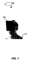
図1は、ユーザ101がVR環境を見るためにヘッドマウント型VRデバイス102を利用するVR構成100を表す。ユーザ101は、ヘッドマウント型VRデバイス102内に位置付けられた、図2に表されているVR表示スクリーン203を見る。様々な実施形態で、VR環境は、現実世界イメージの捕捉された立体画像を有している。立体画像は、合成イメージとしてVR環境においてレンダリングされる。ユーザ101は、様々なモダリティ、例えば、頭部旋回、ヘッドマウント型VRデバイスに位置付けられたマイクロホンにボイス入力を供給すること、ヘッドマウント型VRデバイス102に位置付けられたアクチュエータにタッチ入力を供給すること、ヘッドマウント型VRデバイス102の近くに位置するアクチュエータにタッチ入力を供給すること、などを介して、VR環境をナビゲートし得る。様々な頭部取付デバイス、例えば、ストラップ構成が、ユーザ101の頭へのVRデバイス102の頭部取り付けを達成するために利用されてよい。VR構成100は、ヘッドマウント型VRデバイス102を利用するものとして表されているが、VRシステムの様々な他の実施形態は、ユーザから離れて位置付けられて、VR表示スクリーンに対するユーザの追跡された頭部の動きに基づきVR環境を変更するVR表示スクリーンを含む。従って、VR構成100は、特定のVRシステムに制限されない。
FIG. 1 depicts a
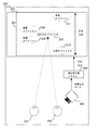
図2は、図1で表されているユーザ101によって見られるヘッドマウント型VRデバイス102の内部コンポーネントの上面図を表す。ユーザ101は、VR環境における様々なオブジェクト207〜211を知覚するよう表示スクリーン203を見る。例えば、ユーザ101の左眼201及び右眼202は、注目のオブジェクト207をじっと見る。視標追跡システム204(例えば、1つ以上の画像捕捉デバイス)は、注目のオブジェクト207を決定するよう目201及び202の注視を捕捉する。視標追跡システム204は、捕捉された視標追跡データを適応焦点面システム205へ供給する。
FIG. 2 depicts a top view of the internal components of the head mounted
様々な実施形態において、視標追跡システム204は、目201及び202の夫々についてカメラ座標系(例えば、x座標及びy座標)を有してよい。世界ジオメトリは、目201及び202の夫々が世界ジオメトリの原点にあると見なされるように、目201及び202の夫々についてのカメラ座標系に従って表され得る。視標追跡システム204は、VR表示スクリーン203における(x,y)ピクセル座標に関して目201及び202の夫々のビュー方向を推定する。
In various embodiments, the
適応焦点面システム205は、目201及び202についての焦点面206を推定するよう、捕捉された視標追跡データのビュー方向を利用する。様々な実施形態において、適応焦点面システム205は、目201及び202が注目のオブジェクト207の同じ点をじっと見ているということに基づいて、焦点面206を単一の焦点面206として推定する。様々な他の実施形態において、適応焦点面システム205は、目201及び202がVR環境におけるオブジェクトの異なる点又は異なるオブジェクトをじっと見ているということに基づいて、目201及び202の夫々についての異なる焦点面を推定する。
The adaptive
適応焦点面システム205は、次いで、VR表示スクリーン203の輝度に基づき目201及び202の瞳孔拡張を推定する。例えば、適応焦点面システム205は、VR表示スクリーン203が低輝度を有しているイメージを出す場合には、目201及び202の大きい瞳孔拡張を推定し得る。そのような瞳孔収縮は、最小限の明暗を有している現実世界のシーンの瞳孔拡張と相互に関連がある。他の例として、適応焦点面システム205は、VR表示スクリーン203が高い輝度を有しているイメージを出す場合には、目201及び202の小さい瞳孔拡張を発生させ得る。そのような瞳孔拡張は、瞳孔拡張が現実世界のシーンにおけるオブジェクトを知覚するには不要であるように、最適な明暗又はほぼ最適な明暗を有しているその現実世界のシーンの瞳孔収縮と相互に関連がある。
The adaptive
適応焦点面システム205は、推定された焦点面206に基づき合成DoFを生成する。適応焦点面システム205は、合成DoF内のオブジェクトのピクセルが明りょうであることを可能にする、又はそのように変更し、一方、適応焦点面システム205は、ブラーが未だ適用されていない場合には、合成DoFの外にあるオブジェクトにブラーを適用する。例えば、注目のオブジェクト207がユーザ101によって明らかに見られて知覚されるよう意図される場合に、注目のオブジェクト207のピクセルは変更されないか、あるいは、適応焦点面システム205によって、如何なるブラーも除去するよう変更される。その上、合成DoF内の前景オブジェクト及び/又は背景オブジェクトも、ユーザ101によって明らかに見られて知覚されるよう意図される。従って、適応焦点面システム205は、そのようなオブジェクトのピクセルが如何なるブラーもなしで見られることを可能にするか、又はそのように変更する。
The adaptive
図2に表されているDoFの例は、VR表示スクリーン203によって発せられた低輝度に基づく大きな瞳孔拡張の推定から生じる低いDoFである。例えば、DoFは、VR表示スクリーン203の全体に満たない最短距離だけ注目のオブジェクト207から前及び後ろに延在するものとして表される。結果として、適応焦点面システム205は、DoF内に存在している前景オブジェクト209及び背景オブジェクト208にブラーを適用せず、DoFの外にある前景オブジェクト210及び背景オブジェクト211にブラーを適用する。
An example of DoF represented in FIG. 2 is the low DoF resulting from the estimation of large pupil dilation based on the low intensity emitted by the
様々な実施形態において、輝度は、VR表示スクリーン203によって表示されるVR環境が合成イメージであることから、予め決定されている。換言すれば、特定のシーンの輝度は、たとえユーザが明るさのような様々な入力を調整するとしても、変化しない。例えば、輝度シーン値は、適応焦点面システム205へ、例えば、ストリーミング、ダウンロード、などを介して供給されるビデオフレーム内に符号化されてよい。それにより、適応焦点面システム205は、特定のシーンに関連した所定の輝度を決定する。様々な実施形態において、適応焦点面システム205は、特定のVRシーンに関連するVR表示スクリーン203によって表示されるコードを解析すること、VR表示スクリーン203から受信されるメタデータを解析すること、特定の画像に関連すると予め決定されるシーンを決定するよう画像解析を行うこと、などによって、特定のシーンを決定してよい。
In various embodiments, the brightness is predetermined because the VR environment displayed by the
ブラーデータは、適応焦点面システム205によって決定される。適応焦点面システム205は、そのようなデータを、レンダリングのために、VR表示スクリーン203へ送ってよい。換言すれば、適応焦点面システム205は、合成DoFの外にある特定のオブジェクト又はオブジェクトの部分にブラー効果をかけるよう表示データを変更してよい。VR表示スクリーン203は、次いで、変更されたデータをレンダリングしてよい。
Blur data is determined by adaptive
適応焦点面システム205は単一のシステムとして表されているが、様々な実施形態において、複数のシステムが、適応焦点面システム205の機能性を実行するために利用されてよい。例えば、第1のシステムは、輝度に基づき瞳孔寸法を推定してよく、第2のシステムは、瞳孔寸法の推定に基づき焦点面を決定するか又は既存の焦点面を適応させてよく、第3のシステムは、焦点面に基づき合成DoFを生成してよく、第4のシステムは、合成DoFに基づきブラー適用を実行してよい。異なる機能性を実行するために利用されるシステムの数は他にもいくつであってもよい。
Although adaptive
適応焦点面システム205は、様々な瞳孔サイズ推定に焦点面を適応させる。図3は、異なる焦点面301及び対応するDoFを有しているヘッドマウント型VRデバイス102の内部コンポーネントの上面図を表す。一例として、図3の適応焦点面システム205は、目201及び202の小さい瞳孔拡張、すなわち、VR表示スクリーン203から発せられた最適な又はほぼ最適な輝度から生じる瞳孔収縮を推定する。結果として、適応焦点面システム205は、全てのオブジェクト207〜211がVR表示スクリーン203によって明りょうにレンダリングされるような高いDoFを計算する。
The adaptive
図4は、図2及び図3で表されている適応焦点面システム205の内部コンポーネントを表す。適応焦点面システム205は、プロセッサ401と、様々な入出力(I/O)デバイス402、例えば、オーディオ/ビデオ出力及びオーディオ/ビデオ入力、テープ・ドライブ、フロッピー(登録商標)・ドライブ、ハードディスク・ドライブ若しくはコンパクトディスク・ドライブを含むがそれらに限られない記憶デバイス、受信器、送信器、スピーカ、ディスプレイ、画像捕捉センサ、例えば、デジタル静止カメラ若しくはデジタルビデオカメラで使用されるもの、クロック、出力ポート、ユーザ入力デバイス、例えば、キーボード、キーパッド、マウス、及び同様のもの、又は発話コマンドを捕捉するマイクロホンと、メモリ403、例えば、ランダム・アクセス・メモリ(“RAM”)(random access memory)及び/又はリード・オンリー・メモリ(“ROM”)(read only memory)と、データ記憶デバイス404と、合成DoF生成コード405とを有する。
FIG. 4 represents the internal components of the adaptive
プロセッサ401は、具体的に、VRシーンのどの部分がブラー効果をかけられるか又はかけられないかを決定するために利用される合成DoFを生成するように合成DoF生成コード405を実行するよう構成される。瞳孔拡張を決定するために計算負荷の重い画像処理を利用した従来のコンピューティング・システムと対照的に、プロセッサ401は、輝度に基づく瞳孔拡張のより計算効率の良い推定を利用する。従って、プロセッサ401は、現実的なVR景観をレンダリングするようブラー適用の処理スピードを改善することによって、コンピュータの機能を改善する。
The
更に、プロセッサ401は、画像処理を介して瞳孔拡張を決定することによるよりも正確な合成DoFを生成するよう輝度値を利用することによって、コンピュータの精度を改善する。換言すれば、プロセッサ401は、どのような瞳孔拡張が、ユーザ101によって調整されているかもしれず且つ瞳孔拡張に対して影響を有している可能性がある特定の明るさレベルよりもむしろ、所定の同姓イメージの特定の輝度値に基づくべきであるかを決定する。よって、合成イメージの輝度の使用は、明るさ調整のような他の制約によって影響を及ぼされる可能性がある瞳孔拡張と比べて、合成DoFを生成するためのより正確な決定因子である。
Further,
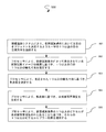
図5は、輝度に基づき焦点面を適応させるよう適応焦点面システム205によって利用されるプロセス500を表す。処理ブロック501で、プロセス500は、視標追跡システム204により、仮想現実装置102の仮想現実表示203において注目のオブジェクト207を決定するようユーザ101の1つ以上の目201及び202の注視方向を追跡する。その上、処理ブロック502で、プロセス500は、プロセッサ401により、仮想現実表示203によって表示されている仮想現実イメージの輝度に基づき、1つ以上の目201及び202の1つ以上の瞳孔寸法を推定する。処理ブロック503で、プロセス500はまた、プロセッサ401により、推定された1つ以上の瞳孔寸法に基づき焦点面206を決定する。更に、処理ブロック504で、プロセス500は、プロセッサ401により、焦点面206に基づき合成DoFを生成する。その上、処理ブロック505で、プロセス500は、プロセッサ401により、仮想現実表示203の1つ以上のピクセルが合成被写界深度の外にあることに基づき、それらの1つ以上のピクセルにブラー効果を適用する。
FIG. 5 depicts a
本願で記載されるプロセスは、図4に表されているプロセッサ401によって実装されてよい。そのようなプロセッサは、プロセスを実行するよう、コンパイルされたアセンブリ又はマシンレベルのいずれかで、命令を実行する。それらの命令は、プロセスに対応する図の記載に従って当業者によって記述され、そして、コンピュータ可読記憶デバイスのようなコンピュータ可読媒体において記憶又は送信され得る。命令はまた、ソースコード又は何らかの他の既知のコンピュータ支援設計ツールを用いて作成されてよい。コンピュータ可読媒体は、それらの命令を運ぶことが可能な如何なる媒体であってもよく、CD−ROM、DVD、磁気又は他の光ディスク、テープ、シリコン・メモリ、例えば、ローカルで若しくは遠隔でネットワークを通じた有線若しくは無線伝送によるリムーバブル、非リムーバブル、揮発性若しくは不揮発性、パケット化された若しくはパケット化されていないデータを含む。コンピュータは、本願では、上述されたような一般的な多目的又は単一目的のプロセッサを有している如何なるデバイスも含むよう意図される。
The processes described herein may be implemented by the
本願で記載される構成は、VRシステムを対象としているが、そのような構成は、拡張現実(“AR”)(augmented reality)システムとの関連でも利用されてよい。ARシステムは、通常、表示システム、例えば、メガネのような、現実世界のイメージの上に仮想イメージをオーバーレイするヘッドマウント型システムを利用する。結果として、ユーザは、仮想イメージがオーバーレイされた現実世界の景観を見ることができる。本願のために提供された構成は、仮想イメージがより現実的に見えるように、仮想イメージの輝度値から生成された瞳孔拡張推定に基づきその仮想イメージの焦点面を調整するために利用されてよい。 Although the configurations described herein are directed to a VR system, such configurations may also be utilized in conjunction with augmented reality ("AR") systems. AR systems typically utilize display systems, for example, head-mounted systems that overlay virtual images over real-world images, such as glasses. As a result, the user can view the real-world landscape on which the virtual image is overlaid. The configuration provided for the present application may be utilized to adjust the focal plane of the virtual image based on pupil dilation estimates generated from the luminance values of the virtual image so that the virtual image looks more realistic .
“及び/又は(and/or)”及び“〜のうちの少なくとも1つ(at least one of)”の使用(例えば、“A及び/又はB”及び“A及びBのうちの少なくとも1つ”の場合)は、最初に挙げられているオプション(A)のみの選択、又は2番目に挙げられているオプション(B)のみの選択、又は両方のオプション(A及びB)の選択を包含するよう意図される。更なる例として、“A、B、及び/又はC”及び“A、B、及びCのうちの少なくとも1つ”の場合に、そのような言い回しは、最初に挙げられているオプション(A)のみの選択、又は2番目に挙げられているオプション(B)のみの選択、又は3番目に挙げられているオプション(C)のみの選択、又は最初と2番目に挙げられているオプション(A及びB)のみの選択、又は最初と3番目に挙げられているオプション(A及びC)のみの選択、又は2番目と3番目に挙げられているオプション(B及びC)のみの選択、又は3つ全てのオプション(A及びB及びC)の選択を包含するよう意図される。これは、挙げられているアイテムの数だけ拡張され得る。 Use of “and / or” and “at least one of” (eg, “A and / or B” and “at least one of A and B” In the case of) to include the selection of only the option (A) listed first, or the selection of only the option (B) listed second, or the selection of both options (A and B) Intended. As a further example, in the case of "A, B, and / or C" and "at least one of A, B, and C", such phrase is the first option listed (A) Or the second option (B) only, or the third option (C) only, or the first and second options (A and B) Selection of only, or selection of only the first and third listed options (A and C), or selection of only the second and third listed options (B and C), or three It is intended to encompass the selection of all options (A and B and C). This can be extended by the number of items listed.
本願で記載されているプロセス、システム、装置、及びコンピュータ・プログラム製品は、他のタイプのプロセス、システム、装置、及びコンピュータ・プログラム製品においても適用されてよいことが理解される。当業者に明らかなように、本願で記載されているプロセス、システム、装置、及びコンピュータ・プログラム製品の実施形態の様々な適応及び変更は、目下のプロセス及びシステムの適用範囲及び精神から外れることなしに構成されてよい。従って、添付の特許請求の範囲の適用範囲の中で、目下のプロセス、システム、装置、及びコンピュータ・プログラム製品は、本願で具体的に記載されている以外にも実施されてよいことが理解されるべきである。 It is understood that the processes, systems, devices and computer program products described herein may be applied in other types of processes, systems, devices and computer program products. It will be apparent to those skilled in the art that various adaptations and modifications of the embodiments of the process, system, apparatus and computer program product described in this application do not depart from the scope and spirit of the current process and system May be configured. It is, therefore, to be understood that, within the scope of the appended claims, the present process, system, apparatus and computer program product may be practiced other than as specifically described herein. It should.
本願で記載されているプロセス、システム、装置、及びコンピュータ・プログラム製品は、他のタイプのプロセス、システム、装置、及びコンピュータ・プログラム製品においても適用されてよいことが理解される。当業者に明らかなように、本願で記載されているプロセス、システム、装置、及びコンピュータ・プログラム製品の実施形態の様々な適応及び変更は、目下のプロセス及びシステムの適用範囲及び精神から外れることなしに構成されてよい。従って、添付の特許請求の範囲の適用範囲の中で、目下のプロセス、システム、装置、及びコンピュータ・プログラム製品は、本願で具体的に記載されている以外にも実施されてよいことが理解されるべきである。
上記の実施形態に加えて、以下の付記を開示する。
(付記1)
仮想現実装置(102)であって、
仮想現実表示スクリーン(203)と、
仮想現実表示(203)において注目のオブジェクト(207)を決定するようユーザの1つ以上の目の注視方向を追跡する視標追跡システム(204)と、
プロセッサ(401)と、
命令の組を有するメモリ(403)と
を有し、
前記命令の組は、前記プロセッサ(401)によって実行される場合に、当該仮想現実装置(102)に、
前記仮想現実表示(203)によって表示されている仮想現実イメージの輝度に基づき前記1つ以上の目の1つ以上の瞳孔寸法を推定させ、
前記推定された1つ以上の瞳孔寸法に基づき焦点面(206)を決定させ、
前記焦点面(206)に基づき合成被写界深度を生成させ、
前記仮想現実表示(203)の1つ以上のピクセルが前記合成被写界深度の外にあることに基づき該1つ以上のピクセルにブラー効果を適用させる、
仮想現実装置(102)。
(付記2)
前記プロセッサ(401)は、更に、当該仮想現実装置(102)に、
前記仮想現実イメージに関連するフレームデータを解析することによって該仮想現実イメージの輝度を決定させる、
付記1に記載の仮想現実装置(102)。
(付記3)
前記プロセッサ(401)は、更に、当該仮想現実装置(102)に、
前記仮想現実表示(203)の1つ以上のピクセルが前記合成被写界深度の中にあることに基づき該1つ以上のピクセルから前のブラー効果を取り除かせる、
付記1に記載の仮想現実装置(102)。
(付記4)
前記視標追跡システム(204)は、1つ以上の画像捕捉デバイスを有する、
付記1に記載の仮想現実装置(102)。
(付記5)
前記視標追跡システム(204)は、前記仮想現実表示(203)においてピクセル座標により前記注視方向を追跡する、
付記1に記載の仮想現実装置(102)。
(付記6)
前記仮想現実イメージは、現実世界の景色の捕捉された立体イメージである、
付記1に記載の仮想現実装置(102)。
(付記7)
当該仮想現実装置(102)をユーザの頭部に取り付ける取付デバイスを更に有する
付記1に記載の仮想現実装置(102)。
(付記8)
前記合成被写界深度の外にある1つ以上のピクセルは、前記合成被写界深度の外にあり且つ注目のオブジェクト(207)の前にある前景オブジェクト(210)に対応する、
付記1に記載の仮想現実装置(102)。
(付記9)
前記合成被写界深度の外にある1つ以上のピクセルは、前記合成被写界深度の外にあり且つ注目のオブジェクト(207)の後ろにある背景オブジェクト(211)に対応する、
付記1に記載の仮想現実装置(102)。
(付記10)
前記プロセッサ(401)は、更に、当該仮想現実装置(102)に、
前記仮想現実イメージのパノラマビューを供給させる、
付記1に記載の仮想現実装置(102)。
(付記11)
視標追跡システム(204)により、仮想現実装置(102)の仮想現実表示(203)において注目のオブジェクト(207)を決定するようユーザの1つ以上の目の注視方向を追跡することと、
プロセッサ(401)により、前記仮想現実表示(203)によって表示されている仮想現実イメージの輝度に基づき前記1つ以上の目の1つ以上の瞳孔寸法を推定することと、
前記プロセッサ(401)により、前記推定された1つ以上の瞳孔寸法に基づき焦点面(206)を決定することと、
前記プロセッサ(401)により、前記焦点面(206)に基づき合成被写界深度を生成することと、
前記プロセッサ(401)により、前記仮想現実表示(203)の1つ以上のピクセルが前記合成被写界深度の外にあることに基づき該1つ以上のピクセルにブラー効果を適用することと
を有する方法。
(付記12)
前記プロセッサ(401)により、前記仮想現実イメージに関連するフレームデータを解析することによって該仮想現実イメージの輝度を決定することを更に有する
付記11に記載の方法。
(付記13)
前記プロセッサ(401)により、前記仮想現実表示(203)の1つ以上のピクセルが前記合成被写界深度の中にあることに基づき該1つ以上のピクセルから前のブラー効果を取り除くことを更に有する
付記11に記載の方法。
(付記14)
前記視標追跡システム(204)は、1つ以上の画像捕捉デバイスを有する、
付記11に記載の方法。
(付記15)
前記視標追跡システム(204)により、前記仮想現実表示(203)においてピクセル座標により前記注視方向を追跡することを更に有する
付記11に記載の方法。
(付記16)
前記仮想現実イメージは、現実世界の景色の捕捉された立体イメージである、
付記11に記載の方法。
(付記17)
前記仮想現実装置(102)は、該仮想現実装置(102)をユーザの頭部に取り付ける取付デバイスを有する、
付記11に記載の方法。
(付記18)
前記合成被写界深度の外にある1つ以上のピクセルは、前記合成被写界深度の外にあり且つ注目のオブジェクト(207)の前にある前景オブジェクト(210)に対応する、
付記11に記載の方法。
(付記19)
前記合成被写界深度の外にある1つ以上のピクセルは、前記合成被写界深度の外にあり且つ注目のオブジェクト(207)の後ろにある背景オブジェクト(211)に対応する、
付記11に記載の方法。
(付記20)
前記仮想現実イメージのパノラマビューを供給することを更に有する
付記11に記載の方法。
(付記21)
視標追跡システム(204)により、仮想現実装置(102)の仮想現実表示(203)において注目のオブジェクト(207)を決定するようユーザの1つ以上の目の注視方向を追跡することと、
プロセッサ(401)により、前記仮想現実表示(203)によって表示されている仮想現実イメージの輝度に基づき前記1つ以上の目の1つ以上の瞳孔寸法を推定することと、
前記プロセッサ(401)により、前記推定された1つ以上の瞳孔寸法に基づき焦点面(206)を決定することと、
前記プロセッサ(401)により、前記焦点面(206)に基づき合成被写界深度を生成することと、
前記プロセッサ(401)により、前記仮想現実表示(203)の1つ以上のピクセルが前記合成被写界深度の外にあることに基づき該1つ以上のピクセルにブラー効果を適用することと
を有する方法を実施するためのコンピュータ実行可能プログラム命令を記憶している非一時的なコンピュータ可読媒体。
(付記22)
前記プロセッサ(401)により、前記仮想現実イメージに関連するフレームデータを解析することによって該仮想現実イメージの輝度を決定することを更に有する
付記21に記載の非一時的なコンピュータ可読媒体。
(付記23)
前記プロセッサ(401)により、前記仮想現実表示(203)の1つ以上のピクセルが前記合成被写界深度の中にあることに基づき該1つ以上のピクセルから前のブラー効果を取り除くことを更に有する
付記21に記載の非一時的なコンピュータ可読媒体。
(付記24)
前記視標追跡システム(204)は、1つ以上の画像捕捉デバイスを有する、
付記21に記載の非一時的なコンピュータ可読媒体。
(付記25)
前記視標追跡システム(204)により、前記仮想現実表示(203)においてピクセル座標により前記注視方向を追跡することを更に有する
付記21に記載の非一時的なコンピュータ可読媒体。
(付記26)
前記仮想現実イメージは、現実世界の景色の捕捉された立体イメージである、
付記21に記載の非一時的なコンピュータ可読媒体。
(付記27)
前記仮想現実装置(102)は、該仮想現実装置(102)をユーザの頭部に取り付ける取付デバイスを有する、
付記21に記載の非一時的なコンピュータ可読媒体。
(付記28)
前記合成被写界深度の外にある1つ以上のピクセルは、前記合成被写界深度の外にあり且つ注目のオブジェクト(207)の前にある前景オブジェクト(210)に対応する、
付記21に記載の非一時的なコンピュータ可読媒体。
(付記29)
前記合成被写界深度の外にある1つ以上のピクセルは、前記合成被写界深度の外にあり且つ注目のオブジェクト(207)の後ろにある背景オブジェクト(211)に対応する、
付記21に記載の非一時的なコンピュータ可読媒体。
(付記30)
前記仮想現実イメージのパノラマビューを供給することを更に有する
付記21に記載の非一時的なコンピュータ可読媒体。
It is understood that the processes, systems, devices and computer program products described herein may be applied in other types of processes, systems, devices and computer program products. It will be apparent to those skilled in the art that various adaptations and modifications of the embodiments of the process, system, apparatus and computer program product described in this application do not depart from the scope and spirit of the current process and system May be configured. It is, therefore, to be understood that, within the scope of the appended claims, the present process, system, apparatus and computer program product may be practiced other than as specifically described herein. It should.
In addition to the above embodiments, the following appendices are disclosed.
(Supplementary Note 1)
A virtual reality device (102),
Virtual reality display screen (203),
An eye tracking system (204) for tracking the gaze direction of the user's eyes to determine the object of interest (207) in the virtual reality display (203);
A processor (401),
A memory (403) with a set of instructions and
Have
The set of instructions, when executed by the processor (401), causes the virtual reality device (102) to:
Causing one or more pupil sizes of the one or more eyes to be estimated based on the brightness of the virtual reality image displayed by the virtual reality display (203);
Causing the focal plane (206) to be determined based on the estimated one or more pupil sizes;
Generating a combined depth of field based on the focal plane (206);
Applying a blur effect to the one or more pixels based on one or more pixels of the virtual reality display (203) being outside the combined depth of field;
Virtual Reality Device (102).
(Supplementary Note 2)
The processor (401) further transmits to the virtual reality device (102)
Determining the intensity of the virtual reality image by analyzing frame data associated with the virtual reality image;
The virtual reality device (102) according to appendix 1.
(Supplementary Note 3)
The processor (401) further transmits to the virtual reality device (102)
Causing one or more pixels of the virtual reality display (203) to remove a previous blur effect from the one or more pixels based on being within the combined depth of field;
The virtual reality device (102) according to appendix 1.
(Supplementary Note 4)
The eye tracking system (204) comprises one or more image capture devices,
The virtual reality device (102) according to appendix 1.
(Supplementary Note 5)
The eye tracking system (204) tracks the gaze direction by pixel coordinates in the virtual reality display (203),
The virtual reality device (102) according to appendix 1.
(Supplementary Note 6)
The virtual reality image is a captured stereo image of a scene of the real world,
The virtual reality device (102) according to appendix 1.
(Appendix 7)
It further comprises a mounting device for mounting the virtual reality device (102) on the head of the user
The virtual reality device (102) according to appendix 1.
(Supplementary Note 8)
The one or more pixels outside the composite depth of field correspond to foreground objects (210) outside the composite depth of field and in front of the object of interest (207)
The virtual reality device (102) according to appendix 1.
(Appendix 9)
The one or more pixels outside the composite depth of field correspond to background objects (211) outside the composite depth of field and behind the object of interest (207)
The virtual reality device (102) according to appendix 1.
(Supplementary Note 10)
The processor (401) further transmits to the virtual reality device (102)
Providing a panoramic view of the virtual reality image,
The virtual reality device (102) according to appendix 1.
(Supplementary Note 11)
Tracking the gaze direction of one or more eyes of the user to determine the object of interest (207) in the virtual reality display (203) of the virtual reality device (102) by the visual target tracking system (204);
Estimating one or more pupil sizes of the one or more eyes based on the luminance of the virtual reality image displayed by the virtual reality display (203) by a processor (401);
Determining a focal plane (206) by the processor (401) based on the estimated one or more pupil sizes;
Generating a composite depth of field based on the focal plane (206) by the processor (401);
Applying a blurring effect to the one or more pixels based on the one or more pixels of the virtual reality display (203) being outside the combined depth of field by the processor (401);
How to have it.
(Supplementary Note 12)
The method further comprises determining the brightness of the virtual reality image by analyzing frame data associated with the virtual reality image by the processor (401).
The method according to appendix 11.
(Supplementary Note 13)
The processor (401) further removes the previous blur effect from the one or more pixels based on one or more pixels of the virtual reality display (203) being within the combined depth of field. Have
The method according to appendix 11.
(Supplementary Note 14)
The eye tracking system (204) comprises one or more image capture devices,
The method according to appendix 11.
(Supplementary Note 15)
The eye tracking system (204) further comprises tracking the gaze direction by pixel coordinates in the virtual reality display (203)
The method according to appendix 11.
(Supplementary Note 16)
The virtual reality image is a captured stereo image of a scene of the real world,
The method according to appendix 11.
(Supplementary Note 17)
The virtual reality device (102) comprises an attachment device for attaching the virtual reality device (102) to the head of the user
The method according to appendix 11.
(Appendix 18)
The one or more pixels outside the composite depth of field correspond to foreground objects (210) outside the composite depth of field and in front of the object of interest (207)
The method according to appendix 11.
(Appendix 19)
The one or more pixels outside the composite depth of field correspond to background objects (211) outside the composite depth of field and behind the object of interest (207)
The method according to appendix 11.
(Supplementary Note 20)
Further comprising providing a panoramic view of the virtual reality image
The method according to appendix 11.
(Supplementary Note 21)
Tracking the gaze direction of one or more eyes of the user to determine the object of interest (207) in the virtual reality display (203) of the virtual reality device (102) by the visual target tracking system (204);
Estimating one or more pupil sizes of the one or more eyes based on the luminance of the virtual reality image displayed by the virtual reality display (203) by a processor (401);
Determining a focal plane (206) by the processor (401) based on the estimated one or more pupil sizes;
Generating a composite depth of field based on the focal plane (206) by the processor (401);
Applying a blurring effect to the one or more pixels based on the one or more pixels of the virtual reality display (203) being outside the combined depth of field by the processor (401);
20. A non-transitory computer readable medium storing computer executable program instructions for performing a method comprising:
(Supplementary Note 22)
The method further comprises determining the brightness of the virtual reality image by analyzing frame data associated with the virtual reality image by the processor (401).
24. The non-transitory computer readable medium according to appendix 21.
(Supplementary Note 23)
The processor (401) further removes the previous blur effect from the one or more pixels based on one or more pixels of the virtual reality display (203) being within the combined depth of field. Have
24. The non-transitory computer readable medium according to appendix 21.
(Supplementary Note 24)
The eye tracking system (204) comprises one or more image capture devices,
24. The non-transitory computer readable medium according to appendix 21.
(Appendix 25)
The eye tracking system (204) further comprises tracking the gaze direction by pixel coordinates in the virtual reality display (203)
24. The non-transitory computer readable medium according to appendix 21.
(Appendix 26)
The virtual reality image is a captured stereo image of a scene of the real world,
24. The non-transitory computer readable medium according to appendix 21.
(Appendix 27)
The virtual reality device (102) comprises an attachment device for attaching the virtual reality device (102) to the head of the user
24. The non-transitory computer readable medium according to appendix 21.
(Appendix 28)
The one or more pixels outside the composite depth of field correspond to foreground objects (210) outside the composite depth of field and in front of the object of interest (207)
24. The non-transitory computer readable medium according to appendix 21.
(Supplementary Note 29)
The one or more pixels outside the composite depth of field correspond to background objects (211) outside the composite depth of field and behind the object of interest (207)
24. The non-transitory computer readable medium according to appendix 21.
(Supplementary note 30)
Further comprising providing a panoramic view of the virtual reality image
24. The non-transitory computer readable medium according to appendix 21.
Claims (30)
仮想現実表示スクリーン(203)と、
仮想現実表示(203)において注目のオブジェクト(207)を決定するようユーザの1つ以上の目の注視方向を追跡する視標追跡システム(204)と、
プロセッサ(401)と、
命令の組を有するメモリ(403)と
を有し、
前記命令の組は、前記プロセッサ(401)によって実行される場合に、当該仮想現実装置(102)に、
前記仮想現実表示(203)によって表示されている仮想現実イメージの輝度に基づき前記1つ以上の目の1つ以上の瞳孔寸法を推定させ、
前記推定された1つ以上の瞳孔寸法に基づき焦点面(206)を決定させ、
前記焦点面(206)に基づき合成被写界深度を生成させ、
前記仮想現実表示(203)の1つ以上のピクセルが前記合成被写界深度の外にあることに基づき該1つ以上のピクセルにブラー効果を適用させる、
仮想現実装置(102)。 A virtual reality device (102),
Virtual reality display screen (203),
An eye tracking system (204) for tracking the gaze direction of the user's eyes to determine the object of interest (207) in the virtual reality display (203);
A processor (401),
A memory (403) having a set of instructions, and
The set of instructions, when executed by the processor (401), causes the virtual reality device (102) to:
Causing one or more pupil sizes of the one or more eyes to be estimated based on the brightness of the virtual reality image displayed by the virtual reality display (203);
Causing the focal plane (206) to be determined based on the estimated one or more pupil sizes;
Generating a combined depth of field based on the focal plane (206);
Applying a blur effect to the one or more pixels based on one or more pixels of the virtual reality display (203) being outside the combined depth of field;
Virtual Reality Device (102).
前記仮想現実イメージに関連するフレームデータを解析することによって該仮想現実イメージの輝度を決定させる、
請求項1に記載の仮想現実装置(102)。 The processor (401) further transmits to the virtual reality device (102)
Determining the intensity of the virtual reality image by analyzing frame data associated with the virtual reality image;
A virtual reality device (102) according to claim 1.
前記仮想現実表示(203)の1つ以上のピクセルが前記合成被写界深度の中にあることに基づき該1つ以上のピクセルから前のブラー効果を取り除かせる、
請求項1に記載の仮想現実装置(102)。 The processor (401) further transmits to the virtual reality device (102)
Causing one or more pixels of the virtual reality display (203) to remove a previous blur effect from the one or more pixels based on being within the combined depth of field;
A virtual reality device (102) according to claim 1.
請求項1に記載の仮想現実装置(102)。 The eye tracking system (204) comprises one or more image capture devices,
A virtual reality device (102) according to claim 1.
請求項1に記載の仮想現実装置(102)。 The eye tracking system (204) tracks the gaze direction by pixel coordinates in the virtual reality display (203),
A virtual reality device (102) according to claim 1.
請求項1に記載の仮想現実装置(102)。 The virtual reality image is a captured stereo image of a scene of the real world,
A virtual reality device (102) according to claim 1.
請求項1に記載の仮想現実装置(102)。 The virtual reality device (102) of claim 1, further comprising a mounting device for attaching the virtual reality device (102) to a user's head.
請求項1に記載の仮想現実装置(102)。 The one or more pixels outside the composite depth of field correspond to foreground objects (210) outside the composite depth of field and in front of the object of interest (207)
A virtual reality device (102) according to claim 1.
請求項1に記載の仮想現実装置(102)。 The one or more pixels outside the composite depth of field correspond to background objects (211) outside the composite depth of field and behind the object of interest (207)
A virtual reality device (102) according to claim 1.
前記仮想現実イメージのパノラマビューを供給させる、
請求項1に記載の仮想現実装置(102)。 The processor (401) further transmits to the virtual reality device (102)
Providing a panoramic view of the virtual reality image,
A virtual reality device (102) according to claim 1.
プロセッサ(401)により、前記仮想現実表示(203)によって表示されている仮想現実イメージの輝度に基づき前記1つ以上の目の1つ以上の瞳孔寸法を推定することと、
前記プロセッサ(401)により、前記推定された1つ以上の瞳孔寸法に基づき焦点面(206)を決定することと、
前記プロセッサ(401)により、前記焦点面(206)に基づき合成被写界深度を生成することと、
前記プロセッサ(401)により、前記仮想現実表示(203)の1つ以上のピクセルが前記合成被写界深度の外にあることに基づき該1つ以上のピクセルにブラー効果を適用することと
を有する方法。 Tracking the gaze direction of one or more eyes of the user to determine the object of interest (207) in the virtual reality display (203) of the virtual reality device (102) by the visual target tracking system (204);
Estimating one or more pupil sizes of the one or more eyes based on the luminance of the virtual reality image displayed by the virtual reality display (203) by a processor (401);
Determining a focal plane (206) by the processor (401) based on the estimated one or more pupil sizes;
Generating a composite depth of field based on the focal plane (206) by the processor (401);
Applying the blur effect to the one or more pixels based on the one or more pixels of the virtual reality display (203) being outside the combined depth of field by the processor (401). Method.
請求項11に記載の方法。 The method according to claim 11, further comprising: determining, by the processor (401), the brightness of the virtual reality image by analyzing frame data associated with the virtual reality image.
請求項11に記載の方法。 The processor (401) further removes the previous blur effect from the one or more pixels based on one or more pixels of the virtual reality display (203) being within the combined depth of field. A method according to claim 11, comprising.
請求項11に記載の方法。 The eye tracking system (204) comprises one or more image capture devices,
The method of claim 11.
請求項11に記載の方法。 The method according to claim 11, further comprising tracking the gaze direction by pixel coordinates in the virtual reality display (203) by the eye tracking system (204).
請求項11に記載の方法。 The virtual reality image is a captured stereo image of a scene of the real world,
The method of claim 11.
請求項11に記載の方法。 The virtual reality device (102) comprises an attachment device for attaching the virtual reality device (102) to the head of the user
The method of claim 11.
請求項11に記載の方法。 The one or more pixels outside the composite depth of field correspond to foreground objects (210) outside the composite depth of field and in front of the object of interest (207)
The method of claim 11.
請求項11に記載の方法。 The one or more pixels outside the composite depth of field correspond to background objects (211) outside the composite depth of field and behind the object of interest (207)
The method of claim 11.
請求項11に記載の方法。 The method of claim 11, further comprising providing a panoramic view of the virtual reality image.
プロセッサ(401)により、前記仮想現実表示(203)によって表示されている仮想現実イメージの輝度に基づき前記1つ以上の目の1つ以上の瞳孔寸法を推定することと、
前記プロセッサ(401)により、前記推定された1つ以上の瞳孔寸法に基づき焦点面(206)を決定することと、
前記プロセッサ(401)により、前記焦点面(206)に基づき合成被写界深度を生成することと、
前記プロセッサ(401)により、前記仮想現実表示(203)の1つ以上のピクセルが前記合成被写界深度の外にあることに基づき該1つ以上のピクセルにブラー効果を適用することと
を有する方法を実施するためのコンピュータ実行可能プログラム命令を記憶している非一時的なコンピュータ可読媒体。 Tracking the gaze direction of one or more eyes of the user to determine the object of interest (207) in the virtual reality display (203) of the virtual reality device (102) by the visual target tracking system (204);
Estimating one or more pupil sizes of the one or more eyes based on the luminance of the virtual reality image displayed by the virtual reality display (203) by a processor (401);
Determining a focal plane (206) by the processor (401) based on the estimated one or more pupil sizes;
Generating a composite depth of field based on the focal plane (206) by the processor (401);
Applying the blur effect to the one or more pixels based on the one or more pixels of the virtual reality display (203) being outside the combined depth of field by the processor (401). Non-transitory computer readable medium storing computer executable program instructions for performing the method.
請求項21に記載の非一時的なコンピュータ可読媒体。 The non-transitory computer readable medium of claim 21, further comprising: determining, by the processor (401), the intensity of the virtual reality image by analyzing frame data associated with the virtual reality image.
請求項21に記載の非一時的なコンピュータ可読媒体。 The processor (401) further removes the previous blur effect from the one or more pixels based on one or more pixels of the virtual reality display (203) being within the combined depth of field. 22. A non-transitory computer readable medium according to claim 21 comprising.
請求項21に記載の非一時的なコンピュータ可読媒体。 The eye tracking system (204) comprises one or more image capture devices,
22. The non-transitory computer readable medium according to claim 21.
請求項21に記載の非一時的なコンピュータ可読媒体。 22. The non-transitory computer readable medium of claim 21, further comprising tracking the gaze direction by pixel coordinates in the virtual reality display (203) by the eye tracking system (204).
請求項21に記載の非一時的なコンピュータ可読媒体。 The virtual reality image is a captured stereo image of a scene of the real world,
22. The non-transitory computer readable medium according to claim 21.
請求項21に記載の非一時的なコンピュータ可読媒体。 The virtual reality device (102) comprises an attachment device for attaching the virtual reality device (102) to the head of the user
22. The non-transitory computer readable medium according to claim 21.
請求項21に記載の非一時的なコンピュータ可読媒体。 The one or more pixels outside the composite depth of field correspond to foreground objects (210) outside the composite depth of field and in front of the object of interest (207)
22. The non-transitory computer readable medium according to claim 21.
請求項21に記載の非一時的なコンピュータ可読媒体。 The one or more pixels outside the composite depth of field correspond to background objects (211) outside the composite depth of field and behind the object of interest (207)
22. The non-transitory computer readable medium according to claim 21.
請求項21に記載の非一時的なコンピュータ可読媒体。 22. The non-transitory computer readable medium of claim 21, further comprising providing a panoramic view of the virtual reality image.
Applications Claiming Priority (3)
| Application Number | Priority Date | Filing Date | Title |
|---|---|---|---|
| US201562273833P | 2015-12-31 | 2015-12-31 | |
| US62/273,833 | 2015-12-31 | ||
| PCT/EP2016/082428 WO2017114755A1 (en) | 2015-12-31 | 2016-12-22 | Configuration for rendering virtual reality with an adaptive focal plane |
Publications (2)
| Publication Number | Publication Date |
|---|---|
| JP2019510991A true JP2019510991A (en) | 2019-04-18 |
| JP2019510991A5 JP2019510991A5 (en) | 2020-01-23 |
Family
ID=57681595
Family Applications (1)
| Application Number | Title | Priority Date | Filing Date |
|---|---|---|---|
| JP2018534138A Pending JP2019510991A (en) | 2015-12-31 | 2016-12-22 | Arrangement for rendering virtual reality with an adaptive focal plane |
Country Status (6)
| Country | Link |
|---|---|
| US (1) | US10713760B2 (en) |
| EP (1) | EP3398004B1 (en) |
| JP (1) | JP2019510991A (en) |
| KR (1) | KR20180099703A (en) |
| CN (1) | CN108885339B (en) |
| WO (1) | WO2017114755A1 (en) |
Families Citing this family (9)
| Publication number | Priority date | Publication date | Assignee | Title |
|---|---|---|---|---|
| US9699433B2 (en) * | 2013-01-24 | 2017-07-04 | Yuchen Zhou | Method and apparatus to produce re-focusable vision with detecting re-focusing event from human eye |
| WO2019086635A1 (en) * | 2017-11-03 | 2019-05-09 | United Screens Gmbh | Display system, mobile device and method for providing three-dimensional views |
| CN107958478B (en) * | 2017-12-15 | 2022-05-03 | 歌尔光学科技有限公司 | Rendering method of object in virtual reality scene and virtual reality head-mounted equipment |
| CN108134928A (en) * | 2017-12-26 | 2018-06-08 | 深圳Tcl新技术有限公司 | VR display methods and device |
| CN111869222B (en) * | 2018-03-22 | 2022-05-17 | 华为技术有限公司 | HTTP-based DASH client network element, method and medium |
| CN111757089A (en) * | 2019-03-29 | 2020-10-09 | 托比股份公司 | Method and system for rendering images with pupil enhancement adjustment of the eye |
| EP3911992A4 (en) * | 2019-04-11 | 2022-03-23 | Samsung Electronics Co., Ltd. | Head-mounted display device and operating method of the same |
| CN110084879B (en) * | 2019-04-28 | 2023-06-27 | 网易(杭州)网络有限公司 | Object processing method, device, medium and electronic equipment in virtual scene |
| CN110458926B (en) * | 2019-08-01 | 2020-11-20 | 北京灵医灵科技有限公司 | Three-dimensional virtualization processing method and system for tomograms |
Citations (6)
| Publication number | Priority date | Publication date | Assignee | Title |
|---|---|---|---|---|
| JP2000354257A (en) * | 1999-06-10 | 2000-12-19 | Sony Corp | Image processor, image processing method and program provision medium |
| JP2004005567A (en) * | 2002-04-09 | 2004-01-08 | Sony Computer Entertainment America Inc | Method for generating computer display image, computer processing system for generating image data, and graphics processor |
| JP2006195084A (en) * | 2005-01-12 | 2006-07-27 | Sharp Corp | Display apparatus |
| US20120113107A1 (en) * | 2010-11-05 | 2012-05-10 | Jun Woo Jang | Image display device and driving method for thereof |
| US20130335404A1 (en) * | 2012-06-15 | 2013-12-19 | Jeff Westerinen | Depth of field control for see-thru display |
| JP2015164235A (en) * | 2012-06-19 | 2015-09-10 | シャープ株式会社 | Image processing system, method, program, and recording medium |
Family Cites Families (14)
| Publication number | Priority date | Publication date | Assignee | Title |
|---|---|---|---|---|
| DE69333674T2 (en) * | 1992-06-02 | 2006-02-02 | Canon K.K. | Optical device for rotation detection of an eyeball of an observer |
| US20110228051A1 (en) * | 2010-03-17 | 2011-09-22 | Goksel Dedeoglu | Stereoscopic Viewing Comfort Through Gaze Estimation |
| JP5529660B2 (en) * | 2010-07-20 | 2014-06-25 | パナソニック株式会社 | Pupil detection device and pupil detection method |
| US8625200B2 (en) * | 2010-10-21 | 2014-01-07 | Lockheed Martin Corporation | Head-mounted display apparatus employing one or more reflective optical surfaces |
| US9323325B2 (en) | 2011-08-30 | 2016-04-26 | Microsoft Technology Licensing, Llc | Enhancing an object of interest in a see-through, mixed reality display device |
| WO2013049248A2 (en) * | 2011-09-26 | 2013-04-04 | Osterhout Group, Inc. | Video display modification based on sensor input for a see-through near-to-eye display |
| JP5572647B2 (en) * | 2012-02-17 | 2014-08-13 | 任天堂株式会社 | Display control program, display control device, display control system, and display control method |
| IL221863A (en) * | 2012-09-10 | 2014-01-30 | Elbit Systems Ltd | Digital system for surgical video capturing and display |
| DE102013212374A1 (en) * | 2013-06-27 | 2014-12-31 | Robert Bosch Gmbh | Method and apparatus for adjusting a representation of an image on a screen |
| TWI516804B (en) * | 2014-01-02 | 2016-01-11 | 廣達電腦股份有限公司 | Head mounted display apparatus and backlight adjustment method thereof |
| US10007350B1 (en) * | 2014-06-26 | 2018-06-26 | Leap Motion, Inc. | Integrated gestural interaction and multi-user collaboration in immersive virtual reality environments |
| GB2533553B (en) | 2014-12-15 | 2020-09-09 | Sony Interactive Entertainment Inc | Image processing method and apparatus |
| GB2536650A (en) * | 2015-03-24 | 2016-09-28 | Augmedics Ltd | Method and system for combining video-based and optic-based augmented reality in a near eye display |
| CN105244008B (en) * | 2015-11-09 | 2017-12-15 | 深圳市华星光电技术有限公司 | A kind of display device and its brightness adjusting method |
-
2016
- 2016-12-22 JP JP2018534138A patent/JP2019510991A/en active Pending
- 2016-12-22 EP EP16819930.5A patent/EP3398004B1/en active Active
- 2016-12-22 US US16/066,310 patent/US10713760B2/en active Active
- 2016-12-22 WO PCT/EP2016/082428 patent/WO2017114755A1/en active Application Filing
- 2016-12-22 KR KR1020187018759A patent/KR20180099703A/en unknown
- 2016-12-22 CN CN201680077396.7A patent/CN108885339B/en active Active
Patent Citations (6)
| Publication number | Priority date | Publication date | Assignee | Title |
|---|---|---|---|---|
| JP2000354257A (en) * | 1999-06-10 | 2000-12-19 | Sony Corp | Image processor, image processing method and program provision medium |
| JP2004005567A (en) * | 2002-04-09 | 2004-01-08 | Sony Computer Entertainment America Inc | Method for generating computer display image, computer processing system for generating image data, and graphics processor |
| JP2006195084A (en) * | 2005-01-12 | 2006-07-27 | Sharp Corp | Display apparatus |
| US20120113107A1 (en) * | 2010-11-05 | 2012-05-10 | Jun Woo Jang | Image display device and driving method for thereof |
| US20130335404A1 (en) * | 2012-06-15 | 2013-12-19 | Jeff Westerinen | Depth of field control for see-thru display |
| JP2015164235A (en) * | 2012-06-19 | 2015-09-10 | シャープ株式会社 | Image processing system, method, program, and recording medium |
Also Published As
| Publication number | Publication date |
|---|---|
| EP3398004B1 (en) | 2021-09-29 |
| EP3398004A1 (en) | 2018-11-07 |
| US20190012771A1 (en) | 2019-01-10 |
| US10713760B2 (en) | 2020-07-14 |
| CN108885339A (en) | 2018-11-23 |
| KR20180099703A (en) | 2018-09-05 |
| WO2017114755A1 (en) | 2017-07-06 |
| CN108885339B (en) | 2021-09-28 |
Similar Documents
| Publication | Publication Date | Title |
|---|---|---|
| CN108885339B (en) | Configuration for rendering virtual reality using an adaptive focal plane | |
| US10948726B2 (en) | IPD correction and reprojection for accurate mixed reality object placement | |
| JP6759371B2 (en) | Systems and methods for creating 3D prenoptic video images | |
| JP6747504B2 (en) | Information processing apparatus, information processing method, and program | |
| US11010958B2 (en) | Method and system for generating an image of a subject in a scene | |
| EP3035681B1 (en) | Image processing method and apparatus | |
| US20150138069A1 (en) | Methods, systems, and computer readable media for unified scene acquisition and pose tracking in a wearable display | |
| US9342861B2 (en) | Alternate viewpoint rendering | |
| US20190371072A1 (en) | Static occluder | |
| JP2019510991A5 (en) | ||
| KR20200117685A (en) | Method for recognizing virtual objects, method for providing augmented reality content using the virtual objects and augmented brodadcasting system using the same | |
| JP6017144B2 (en) | Image processing apparatus and method, program, and recording medium | |
| JP6685241B2 (en) | Stereoscopic video generation | |
| JP2023551864A (en) | Three-dimensional (3D) facial feature tracking for autostereoscopic telepresence systems | |
| JP6490107B2 (en) | Stereoscopic video zooming | |
| KR101939243B1 (en) | Stereoscopic depth adjustment and focus point adjustment | |
| US20240078743A1 (en) | Stereo Depth Markers | |
| US20220232201A1 (en) | Image generation system and method |
Legal Events
| Date | Code | Title | Description |
|---|---|---|---|
| A521 | Request for written amendment filed |
Free format text: JAPANESE INTERMEDIATE CODE: A523 Effective date: 20180703 |
|
| A521 | Request for written amendment filed |
Free format text: JAPANESE INTERMEDIATE CODE: A523 Effective date: 20191204 |
|
| A621 | Written request for application examination |
Free format text: JAPANESE INTERMEDIATE CODE: A621 Effective date: 20191204 |
|
| A131 | Notification of reasons for refusal |
Free format text: JAPANESE INTERMEDIATE CODE: A131 Effective date: 20201020 |
|
| A02 | Decision of refusal |
Free format text: JAPANESE INTERMEDIATE CODE: A02 Effective date: 20210518 |