JP2019507092A - Thermally tempered glass sheet with microscale refractive index or birefringence pattern - Google Patents
Thermally tempered glass sheet with microscale refractive index or birefringence pattern Download PDFInfo
- Publication number
- JP2019507092A JP2019507092A JP2018539906A JP2018539906A JP2019507092A JP 2019507092 A JP2019507092 A JP 2019507092A JP 2018539906 A JP2018539906 A JP 2018539906A JP 2018539906 A JP2018539906 A JP 2018539906A JP 2019507092 A JP2019507092 A JP 2019507092A
- Authority
- JP
- Japan
- Prior art keywords
- sheet
- main surface
- tempered glass
- regions
- glass sheet
- Prior art date
- Legal status (The legal status is an assumption and is not a legal conclusion. Google has not performed a legal analysis and makes no representation as to the accuracy of the status listed.)
- Pending
Links
Images


Classifications
-
- C—CHEMISTRY; METALLURGY
- C03—GLASS; MINERAL OR SLAG WOOL
- C03B—MANUFACTURE, SHAPING, OR SUPPLEMENTARY PROCESSES
- C03B29/00—Reheating glass products for softening or fusing their surfaces; Fire-polishing; Fusing of margins
- C03B29/04—Reheating glass products for softening or fusing their surfaces; Fire-polishing; Fusing of margins in a continuous way
- C03B29/06—Reheating glass products for softening or fusing their surfaces; Fire-polishing; Fusing of margins in a continuous way with horizontal displacement of the products
- C03B29/08—Glass sheets
-
- C—CHEMISTRY; METALLURGY
- C03—GLASS; MINERAL OR SLAG WOOL
- C03B—MANUFACTURE, SHAPING, OR SUPPLEMENTARY PROCESSES
- C03B27/00—Tempering or quenching glass products
- C03B27/016—Tempering or quenching glass products by absorbing heat radiated from the glass product
-
- C—CHEMISTRY; METALLURGY
- C03—GLASS; MINERAL OR SLAG WOOL
- C03B—MANUFACTURE, SHAPING, OR SUPPLEMENTARY PROCESSES
- C03B27/00—Tempering or quenching glass products
- C03B27/04—Tempering or quenching glass products using gas
- C03B27/0413—Stresses, e.g. patterns, values or formulae for flat or bent glass sheets
-
- C—CHEMISTRY; METALLURGY
- C03—GLASS; MINERAL OR SLAG WOOL
- C03B—MANUFACTURE, SHAPING, OR SUPPLEMENTARY PROCESSES
- C03B27/00—Tempering or quenching glass products
- C03B27/04—Tempering or quenching glass products using gas
- C03B27/044—Tempering or quenching glass products using gas for flat or bent glass sheets being in a horizontal position
- C03B27/048—Tempering or quenching glass products using gas for flat or bent glass sheets being in a horizontal position on a gas cushion
-
- C—CHEMISTRY; METALLURGY
- C03—GLASS; MINERAL OR SLAG WOOL
- C03B—MANUFACTURE, SHAPING, OR SUPPLEMENTARY PROCESSES
- C03B35/00—Transporting of glass products during their manufacture, e.g. hot glass lenses, prisms
- C03B35/14—Transporting hot glass sheets or ribbons, e.g. by heat-resistant conveyor belts or bands
- C03B35/22—Transporting hot glass sheets or ribbons, e.g. by heat-resistant conveyor belts or bands on a fluid support bed, e.g. on molten metal
- C03B35/24—Transporting hot glass sheets or ribbons, e.g. by heat-resistant conveyor belts or bands on a fluid support bed, e.g. on molten metal on a gas support bed
-
- C—CHEMISTRY; METALLURGY
- C03—GLASS; MINERAL OR SLAG WOOL
- C03C—CHEMICAL COMPOSITION OF GLASSES, GLAZES OR VITREOUS ENAMELS; SURFACE TREATMENT OF GLASS; SURFACE TREATMENT OF FIBRES OR FILAMENTS MADE FROM GLASS, MINERALS OR SLAGS; JOINING GLASS TO GLASS OR OTHER MATERIALS
- C03C23/00—Other surface treatment of glass not in the form of fibres or filaments
- C03C23/007—Other surface treatment of glass not in the form of fibres or filaments by thermal treatment
-
- C—CHEMISTRY; METALLURGY
- C03—GLASS; MINERAL OR SLAG WOOL
- C03C—CHEMICAL COMPOSITION OF GLASSES, GLAZES OR VITREOUS ENAMELS; SURFACE TREATMENT OF GLASS; SURFACE TREATMENT OF FIBRES OR FILAMENTS MADE FROM GLASS, MINERALS OR SLAGS; JOINING GLASS TO GLASS OR OTHER MATERIALS
- C03C2204/00—Glasses, glazes or enamels with special properties
- C03C2204/08—Glass having a rough surface
Landscapes
- Chemical & Material Sciences (AREA)
- Engineering & Computer Science (AREA)
- Materials Engineering (AREA)
- Organic Chemistry (AREA)
- Physics & Mathematics (AREA)
- Thermal Sciences (AREA)
- Life Sciences & Earth Sciences (AREA)
- Chemical Kinetics & Catalysis (AREA)
- General Chemical & Material Sciences (AREA)
- Geochemistry & Mineralogy (AREA)
- Mathematical Physics (AREA)
- Re-Forming, After-Treatment, Cutting And Transporting Of Glass Products (AREA)
- Surface Treatment Of Glass (AREA)
Abstract
強化ガラス又はガラスセラミックシートであって、10μm×10μmの領域にわたり、0.05nmを超え0.8nmRa未満の粗さを有し、シートの外端面から厚さの3倍以内の領域を除き、シートの第1の面の1つ以上の低冷却速度効果発現領域に接する、シートの第1の主面に沿った距離にわたり、熱的に生成又は熱の影響を受けたガラス特性の測定値の傾斜が、シートの第1の面の他の部分より高く、1つ以上の領域の少なくとも1つが、第1の主面に平行な方向に、100000μm未満の最短直線寸法を有するシート。A tempered glass or glass-ceramic sheet having a roughness of more than 0.05 nm and less than 0.8 nm Ra over a region of 10 μm × 10 μm, except for a region within 3 times the thickness from the outer end surface of the sheet, The gradient of the measurements of the glass properties that are thermally generated or affected by heat over a distance along the first major surface of the sheet that is in contact with one or more low cooling rate effect areas of the first surface of Is higher than the rest of the first side of the sheet and at least one of the one or more regions has a shortest linear dimension of less than 100000 μm in a direction parallel to the first major surface.
Description
本出願は、その内容に依拠し、参照により、全内容が本明細書に援用される、2016年1月31日出願の米国仮特許出願第62/289,334号、及び2016年11月30日出願の米国仮特許出願第62/428,263号の優先権を主張するものである。 This application is based on the contents of which and is hereby incorporated by reference in its entirety, U.S. Provisional Patent Application No. 62 / 289,334, filed January 31, 2016, and November 30, 2016. This claims the priority of US Provisional Patent Application No. 62 / 428,263, filed in Japan.
本出願は、2016年1月28日出願の米国仮特許出願第62/288,177号、2016年1月29日出願の米国仮特許出願第62/288,615号、2016年11月30日出願の米国仮特許出願第62/428,142号、2016年11月30日出願の米国仮特許出願第62/428,168号、2016年1月29日出願の米国仮特許出願第62/288,851号、2015年7月30日出願の米国特許出願第14/814,232号、2015年7月30日出願の米国特許出願第14/814,181号、2015年7月30日出願の米国特許出願第14/814,274号、2015年7月30日出願の米国特許出願第14/814,293号、2015年7月30日出願の米国特許出願第14/814,303号、2015年7月30日出願の米国特許出願第14/814,363号、2015年7月30日出願の米国特許出願第14/814,319号、2015年7月30日出願の米国特許出願第14/814,335号、2014年7月31日出願の米国仮特許出願第62/031,856号、2014年11月4日出願の米国仮特許出願第62/074,838号、2015年4月14日出願の米国仮特許出願第62/031,856号、2015年7月30日出願の米国特許出願第14/814,232号、2015年7月30日出願の米国特許出願第14/814,181号、2015年7月30日出願の米国特許出願第14/814,274号、2015年7月30日出願の米国特許出願第14/814,293号、2015年7月30日出願の米国特許出願第14/814,303号、2015年7月30日出願の米国特許出願第14/814,363号、2015年7月30日出願の米国特許出願第14/814,319号、2015年7月30日出願の米国特許出願第14/814,335号、2015年10月2日出願の米国仮特許出願第62/236,296号、2016年1月29日出願の米国仮特許出願第62/288,549号、2016年1月29日出願の米国仮特許出願第62/288,566号、2016年1月29日出願の米国仮特許出願第62/288,615号、2016年1月29日出願の米国仮特許出願第62/288,695号、及び2016年1月29日出願の米国仮特許出願第62/288,755号に関連し、ここに参照することにより、完全に本明細書に援用されるものである。 This application is based on US Provisional Patent Application No. 62 / 288,177, filed January 28, 2016, US Provisional Patent Application No. 62 / 288,615, filed January 29, 2016, November 30, 2016. U.S. Provisional Patent Application No. 62 / 428,142, U.S. Provisional Patent Application No. 62 / 428,168, filed Nov. 30, 2016, U.S. Provisional Patent Application No. 62/288, filed Jan. 29, 2016 , 851, U.S. Patent Application No. 14 / 814,232, filed July 30, 2015, U.S. Patent Application No. 14 / 814,181, filed July 30, 2015, filed July 30, 2015. U.S. Patent Application No. 14 / 814,274, U.S. Patent Application No. 14 / 814,293, filed July 30, 2015, U.S. Patent Application No. 14 / 814,303, filed July 30, 2015, 2 U.S. Patent Application No. 14 / 814,363, filed July 30, 2015, U.S. Patent Application No. 14 / 814,319, filed July 30, 2015, U.S. Patent Application, filed July 30, 2015 No. 14 / 814,335, U.S. Provisional Patent Application No. 62 / 031,856, filed July 31, 2014, U.S. Provisional Patent Application No. 62 / 074,838, filed Nov. 4, 2014, April 2015. U.S. Provisional Patent Application No. 62 / 031,856 filed on May 14, US Patent Application No. 14 / 814,232 filed July 30, 2015, U.S. Patent Application No. 14 / filed on July 30, 2015 No. 814,181, U.S. Patent Application No. 14 / 814,274, filed July 30, 2015, U.S. Patent Application No. 14 / 814,293, filed July 30, 2015, issued July 30, 2015 U.S. Patent Application No. 14 / 814,303, U.S. Patent Application No. 14 / 814,363, filed July 30, 2015, U.S. Patent Application No. 14 / 814,319, filed July 30, 2015, U.S. Patent Application No. 14 / 814,335, filed July 30, 2015, U.S. Provisional Patent Application No. 62 / 236,296, filed Oct. 2, 2015, U.S. Provisional Patent, filed Jan. 29, 2016 Application No. 62 / 288,549, US Provisional Patent Application No. 62 / 288,566, filed January 29, 2016, US Provisional Patent Application No. 62 / 288,615, filed January 29, 2016, 2016 In connection with U.S. Provisional Patent Application No. 62 / 288,695, filed Jan. 29, 2009, and U.S. Provisional Patent Application No. 62 / 288,755, filed Jan. 29, 2016, by reference herein, Which is hereby fully incorporated by reference.
本開示は向上した熱強化ガラスに関し、具体的には、標準的な熱強化によって一般的に製造可能なガラスシートより高い全体的な均一性、及び微小スケール屈折率又は複屈折パターンを有するガラスシートに関するものである。 The present disclosure relates to improved heat-strengthened glass, and in particular, glass sheets having a higher overall uniformity and a microscale refractive index or birefringence pattern than glass sheets that are generally manufacturable by standard heat strengthening. It is about.
特許文献1は、ガラスシートを加熱及び/又は熱強化するための方法及び装置を開示している。本特許文献1は、米国法において、その内容に依拠し、参照により全内容が本明細書に援用される。
定義
「ガラスシート」及び「ガラスリボン」という語句は、本明細書及び特許請求の範囲において広い意味に使用され、1つ以上のガラス及び/又は1つ以上のガラスセラミックスを含むシート及びリボン、並びに1つ以上のガラス及び/又は1つ以上のガラスセラミックスを含むラミネート体又は他の複合体を含む。「ガラスシート」という語句は、ガラスシート及びガラスリボンを集合的に指すのに使用される。「ガラス」には、ガラス及びガラスセラミックスとして知られている材料が含まれる。
The terms “glass sheet” and “glass ribbon” are used broadly throughout the specification and claims, and include sheets and ribbons comprising one or more glasses and / or one or more glass ceramics, and Including laminates or other composites comprising one or more glasses and / or one or more glass ceramics. The phrase “glass sheet” is used to refer collectively to glass sheets and glass ribbons. “Glass” includes materials known as glass and glass ceramics.
実施形態によれば、強化ガラスシートは第1の主面と、第1の主面に対向する第2の主面と、第1の主面と第2主面との間に位置する内部領域と、第1の主面と第2主面との間に延在し、シートの外周を画成するように、第1及び第2の主面に接する外端面とを備え、シートがガラスを含み、熱強化されて成り、第1の主面が、10μm×10μmの領域にわたり、0.05〜0.8nmRaの粗さを有し、シートの外端面から厚さの3倍以内の領域を除き、シートの第1の表面の1つ以上の低冷却速度効果発現領域に接する、シートの第1の主面に沿った距離にわたり、熱的に生成又は熱の影響を受けたガラス特性の測定値の傾斜が、シートの第1の面の他の部分より高く、1つ以上の領域の少なくとも1つが、第1の主面に平行な方向に、100000μm未満、又は僅か若しくはほんの3000、2000、1000、500、400、300、200、150、100、70、50、40、更には30μmの最短直線寸法を有している。 According to the embodiment, the tempered glass sheet has a first main surface, a second main surface facing the first main surface, and an internal region located between the first main surface and the second main surface. And an outer end surface extending between the first main surface and the second main surface and in contact with the first and second main surfaces so as to define an outer periphery of the sheet, wherein the sheet is made of glass. And the first main surface has a roughness of 0.05 to 0.8 nm Ra over a region of 10 μm × 10 μm, and a region within 3 times the thickness from the outer end surface of the sheet. Except measurement of thermally generated or heat-affected glass properties over a distance along the first major surface of the sheet that is in contact with one or more low cooling rate effect areas of the first surface of the sheet The slope of the value is higher than the rest of the first surface of the sheet, and at least one of the one or more regions is in a direction parallel to the first major surface, Less 00000Myuemu, or slightly or only a 3000,2000,1000,500,400,300,200,150,100,70,50,40, further has a shortest linear dimension of 30 [mu] m.
実施形態によれば、熱的に生成又は影響を受けた特性は、ASTM F218に基づき、第1の主面に垂直な透過光で測定したスルーシート遅延特性である。この遅延の傾斜は1mm当り少なくとも5nm、1mm当り10nm、1mm当り20nm、1mm当り30nm、更には1mm当り40、50、60、80、又は100nmであり、これ等はすべてシートの厚さ1mm当りの値である。 According to an embodiment, the thermally generated or affected characteristic is a through sheet delay characteristic measured with transmitted light perpendicular to the first major surface based on ASTM F218. The delay slope is at least 5 nm per mm, 10 nm per mm, 20 nm per mm, 30 nm per mm, and even 40, 50, 60, 80, or 100 nm per mm, all of which are per 1 mm of sheet thickness. Value.
実施形態によれば、熱的に生成又は影響を受けた特性は、シートを透過する第1の主面に垂直な透過光で測定した光屈折率であってよい。この屈折率の傾斜は、前述の1つ以上の領域に向かう方向が正であり、少なくとも1mm当り0.00001、又は少なくとも0.0001、0.001、0.01、更には1mm当り0.1である。 According to embodiments, the thermally generated or affected property may be a light refractive index measured with transmitted light perpendicular to the first major surface that is transmitted through the sheet. This gradient of refractive index is positive in the direction toward one or more of the aforementioned regions, and is at least 0.00001 per mm, or at least 0.0001, 0.001, 0.01, or even 0.1 per mm. It is.
実施形態によれば、熱的に生成又は影響を受けた特性は、仮想温度であってよい。測定目的として、仮想温度は、特許文献1に開示及び記載の強化応力補償ラマン分光シフトによって測定される。前述の1つ以上の領域に接するこの仮想温度の傾斜は、1つ以上の領域に向かう方向が負であってよい。この仮想温度の傾斜は、1mm当り少なくとも5℃、又は1mm当り10、15、20、25、30、40、50、70、更には1mm当り100℃であってよい。 According to embodiments, the thermally generated or affected property may be a fictive temperature. For measurement purposes, the fictive temperature is measured by the enhanced stress compensated Raman spectral shift disclosed and described in US Pat. The slope of this fictive temperature in contact with the one or more regions may be negative in the direction toward the one or more regions. This slope of the fictive temperature may be at least 5 ° C. per mm, or 10, 15, 20, 25, 30, 40, 50, 70 per mm, or even 100 ° C. per mm.
前述の他のすべての実施形態と両立し得る、更に別の実施形態によれば、強化ガラスシートの第1の表面の1つ以上の領域は、ヒートシンクのガス支持面の貫通孔のパターンに対応するパターンに配置することができる。これ等の領域は、ヒートシンクのガス支持面の貫通孔のパターンの一部のみに対応するパターンに配置することもできる。更に、これ等の領域は、ヒートシンクのガス支持面の貫通孔のパターンに対応しないパターンに配置することもできる。 According to yet another embodiment, compatible with all the other embodiments described above, one or more regions of the first surface of the tempered glass sheet correspond to a pattern of through holes in the gas support surface of the heat sink. Can be arranged in a pattern. These regions can be arranged in a pattern corresponding to only a part of the pattern of the through holes on the gas support surface of the heat sink. Further, these regions can be arranged in a pattern that does not correspond to the pattern of the through holes in the gas support surface of the heat sink.
実施形態によれば、潜在的に有用な用途には、1つ以上の領域のパターンが、ロゴ若しくは他の認識可能な記号、又は機械可読パターンを形成する用途が含まれる。 According to embodiments, potentially useful applications include applications in which the pattern of one or more regions forms a logo or other recognizable symbol, or machine-readable pattern.
実施形態によれば、前述の1つ以上の領域の一部を形成しない第1の主面の領域において、ASTM F218に基づき、第1の主面の1つ以上の領域の境界間の中心線に沿って、及び/又は厚さの3倍以内の外端面までのシート距離を除き、1つ以上の領域の境界とシートの外端面との間に沿って、距離d、0.01mm≦d≦1000mmの間隔で存在する位置において、第1の主面を通して取得した一連の示差遅延測定サンプルN=10の正規化標準偏差Sn、 According to the embodiment, in the region of the first main surface that does not form part of the one or more regions described above, the center line between the boundaries of the one or more regions of the first main surface based on ASTM F218 And / or along the distance between the boundary of one or more regions and the outer edge surface of the sheet, excluding the sheet distance to the outer edge surface within 3 times the thickness and / or the distance d, 0.01 mm ≦ d Normalized standard deviation Sn of a series of differential delay measurement samples N = 10 acquired through the first major surface at positions present at intervals of ≦ 1000 mm,

が0.05、0.02、0.015、0.01、0.005、0.002以下、更には0.001以下である。距離dは、0.1mm≦d≦100mm、0.1mm≦d≦100mm、及び1mm≦d≦10mmであってよく、サンプルの数Nは10、100、500、1000、10000であってよい。 Is 0.05, 0.02, 0.015, 0.01, 0.005, 0.002 or less, and further 0.001 or less. The distance d may be 0.1 mm ≦ d ≦ 100 mm, 0.1 mm ≦ d ≦ 100 mm, and 1 mm ≦ d ≦ 10 mm, and the number of samples N may be 10, 100, 500, 1000, 10,000.
ガラスシートを製造するための装置及び方法も開示されている。 An apparatus and method for manufacturing glass sheets is also disclosed.
参照符号は単に読者の便宜を図るためのものであって、本発明の範囲を限定すると解釈されることを意図するものでも、そう解釈されるべきものでもない。より一般的には、前述の概要説明及び以下の詳細な説明は、単に本発明の例示であって、本発明の本質及び特徴を理解するための概要、及び枠組みの提供を意図したものであることを理解されたい。 Reference signs are for the convenience of the reader only and are not intended or should be construed as limiting the scope of the invention. More generally, the foregoing general description and the following detailed description are merely exemplary of the invention and are intended to provide an overview and framework for understanding the nature and features of the invention. Please understand that.
本発明の更なる特徴及び効果は、これに続く詳細な説明に述べてあり、当業者はその記述から、一部は容易に明らかであり、本明細書に例示する本発明を実施することによって認識できるであろう。添付図面は、本発明について更なる理解が得られることを意図して添付したもので、本明細書に組み込まれ、その一部を構成するものである。本明細書および図面(縮尺通りではない)に開示の本発明の様々な特徴は、個別に、及び任意に組み合わせて使用できることを理解されたい。 Additional features and advantages of the invention will be set forth in the detailed description that follows, and will be readily apparent to those skilled in the art from the description, and by practice of the invention illustrated herein. It will be recognized. The accompanying drawings are included to provide a further understanding of the invention and are incorporated in and constitute a part of this specification. It should be understood that the various features of the invention disclosed in the specification and drawings (not to scale) can be used individually and in any combination.
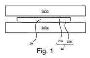
図1は、ガラスシート10を加熱又は冷却するための1対のヒートシンク又は熱源Si/Soの配置の実施形態を示す概略側断面図である。シート10とヒートシンク又は熱源Si/Soとの間の狭い間隙には、全体の加熱又冷却の少なくとも20%、望ましくは、30、40、50、60、更には70、80、又は90%以上が伝導によるように、熱を伝導してシート10を加熱又は冷却するガスが含まれている。シート10は、超音波エネルギー、静電気力等の代替物を含むが、好ましくは間隙20(第1の間隙20a及び第2の間隙20b)に形成されるガスベアリングを含む、任意の適切な、最も好ましくは、非接触手段によって、2つのヒートシンク又は熱源Si/Soの間に支持される。
FIG. 1 is a schematic cross-sectional side view illustrating an embodiment of an arrangement of a pair of heat sinks or heat sources Si / So for heating or cooling a
シート10はヒートシンク間又は熱源間Si/Soにおいて、静止していても動いていてもよい。シート10は、ヒートシンク又は熱源Si/Soの及ぶ範囲(一方又は両方の寸法)より小さくても大きくてもよい(好ましくは一方の寸法のみ、この場合、より大きい方向の連続処理が好ましい)。シート10は同時に加熱又は冷却される複数のシートであってよい。第1及び第2の間隙20a、20b中のガスは、同じであっても異なっていてもよく、両方又はいずれか一方が、ガス混合物であっても本質的に純粋なガスであってもよい。一般に、比較的熱伝導率が高いガス又はガス混合物が好ましい。ガスベアリングを使用することによって、間隙20a、20bを確実に所望の大きさに維持することができ、液体又は固体との直接接触による冷却又は加熱と比較して、及び強制空気対流による冷却と比較して、間隙20の全領域にわたり、比較的均一な熱伝導率が可能になる。
The
図2の概略的な断面で示すように、熱テンパリング又は熱強化装置8は、概して、加熱ゾーン30及び冷却ゾーン40の両方を有し、いずれも、図1に示す狭い間隙20によって、シートから分離された熱源対So又はヒートシンク対Siの形態を成すことができる。別法として、加熱ゾーンは、ここに示した熱源Soの狭い間隙配置ではなく、従来の加熱炉又はオーブンの形態であってもよい。一般に、加熱ゾーン30は、熱強化のために十分な温度にガラスシートを加熱し、冷却ゾーン40は、シートが(その後)最終的に周囲温度になったとき、所望のレベルの熱強化を達成するのに十分な速度かつ十分な時間、シートの表面を介して熱を除去することによってシートの温度を低下させる。シート10は、強化効果を生じさせるのに十分な温度(一般に、ガラス転移点とガラス軟化点との間)に加熱され、冷却ゾーンで冷却される。移送は適切な手段で行うことができる。
As shown in the schematic cross section of FIG. 2, the thermal tempering or heat strengthening device 8 generally has both a
図4は、ガラスを含むシート10であって、第1の主面12、第1の主面に対向する第2の主面14(図では不明瞭な下面)、第1の主面と第2の主面との間に位置する内部領域I、及び第1の主面と第2の主面との間に延在し、シートの外周を画成するように、第1及び第2の主面を包囲する外端面16を有するシートの斜視図である。x−y−z座標が、参照を容易にするために示してあり、zが厚さ方向である。
FIG. 4 shows a
別の実施形態としてのガスベアリングは、図5及び図6に示すいずれかの形態を取ることができる。図5はヒートシンク又は熱源Si/Soの1つの実施形態の概略側断面図であり、図6はヒートシンク又は熱源Si/Soの別の実施形態の概略側断面図である。これ等の実施形態のいずれにおいても、円形構造は、熱制御構造34であって、実施形態が熱源Soの場合には、カートリッジヒータ等であり、実施形態がヒートシンクSiの場合には、冷却剤通路等である。図5の実施形態は、プレナム38から内部を通してガスを供給することができる離散孔36を採用している。図6の実施形態は、内部を通して、プレナム38から同様にガスを供給することができる多孔質構造42を含み、基本的に多孔質構造42の表面44のあらゆる部分からガスが放出されるという効果を有している。
The gas bearing as another embodiment can take any of the forms shown in FIGS. 5 and 6. FIG. 5 is a schematic cross-sectional side view of one embodiment of a heat sink or heat source Si / So, and FIG. 6 is a schematic side cross-sectional view of another embodiment of the heat sink or heat source Si / So. In any of these embodiments, the circular structure is the
図2の熱強化装置において、図5及び図6に示すようなガスベアリング、又は別の適切な非接触手段の使用によって、非接触処理及び取り扱いが可能であるため、シート10の第1の主面12は、フロートガラスの「空気側」のフロート時品質、又は溶融延伸ガラスのいずれかの面の延伸時品質を保持することによって達成される、非常に低い粗さを有することができる。ISO規格19606に基づく、第1の主面の10μm×10μmの領域にわたって測定されるRa粗さが、0.05又は0.1nmから、20、4、0.8、0.7、0.6、0.5、0.4、0.3、更には0.2nmRaまでの範囲である。対向するガスベアリングの自己修復又は自己センタリング効果も、薄いガラスシート、例え非常に薄いシートであっても、平坦に維持するのに役立つ。厚いシートだけでなく、0.1、0.2、又は0.5mmから、3、2.8、2.6、2.4、2.2、2.0、1.8、1.6、1.4、1.2、1.1、1、0.9、0.8、0.7、0.6mmまでの範囲の厚さを有するシートも処理することができる。
In the heat strengthening device of FIG. 2, the first main body of the
冷却ゾーン40において、シート10の領域にわたって、均一な冷却効果を得るためには、間隙20を所望のサイズに維持する必要がある。冷却ゾーン内の間隙20a、20b内のガスの均質性を維持することが重要であることも判明している。熱源の間隙Soとヒートシンクの間隙Siとで異なるガスを使用する場合には、異なるガスが冷却ゾーンのヒートシンクSi内(又は熱源So内)で混合しないように、適切な吸引手段又は真空手段によって、図2の矢印Aで示す熱源SoとヒートシンクSiとの間の位置において、ガスを引き出すことができる。別法として、及び任意として、ガスが異なる場合、特許文献1に開示の加熱ゾーンと冷却ゾーンとの間に位置する遷移ゾーンに、冷却ゾーンと同じガスを供給して、加熱ゾーンガスを冷却ゾーンガスから物理的に隔離することができる。興味深いことに、強制対流ガス強化とは対照的に、(本開示の場合のように)ガスが同一であり、伝導が支配的な熱伝達モードの場合、シート10と共に、ホットゾーン30からコールドゾーン40へ移動する高温ガスは、ガスの熱質量が伝導の効果と比較して無視できるため、本プロセスにおいて非常に重要な要素ではない。
In order to obtain a uniform cooling effect over the area of the
加熱中の熱伝達速度の良好な均一性と、その結果生じる均一な温度プロファイル及びシート10の最終特性を得るためには、加熱エネルギーの不均一な分布を与える熱源Soを用意することも望ましい。図3は、熱源So内に配置されたカートリッジヒータ32の形態を成す、加熱エネルギーのかかる不均一な分布を有する、図1及び2に示すような熱源Soの概略平断面図である。図の熱源Soの左右の端部近くのカートリッジヒータの第1の間隔S1は、熱源Soのより中央の領域のカートリッジヒータの第2の間隔S2より接近している。これは、ほとんどの状況において望ましい、熱源の左端及び右端の周囲環境に対する熱損失のバランスを取るという効果を有している。同様に、カートリッジヒータ32内の巻線は、熱源Soのより中央の領域における第2の平均巻線密度W2より大きい、第1の平均巻線密度W1を熱源Soの端部(図の上部および下部)近くに有することができる。
In order to obtain good uniformity of the heat transfer rate during heating and the resulting uniform temperature profile and final properties of the
図3の熱源So又は他の適切な手段等によって達成することができる、冷却直前のシートの熱プロファイルの良好な制御、及び図2に関連して説明した、ヒートシンクSi内の望ましくないガスの混合を防止するために取られる措置、又は他の適切な手段によって、特にガラスの厚さ及びガラスの特性の関数として達成される強化と比較して、非常に良好な品質を有するガラスを含む、熱強化シートを製造することができる。特に、向上した特性の中に、向上した膜応力の均一性を含めることができる。 Good control of the thermal profile of the sheet just prior to cooling, such as can be achieved by the heat source So of FIG. 3 or other suitable means, and undesired gas mixing in the heat sink Si described in connection with FIG. Heat, including glass with very good quality, as compared to the strengthening achieved by measures taken to prevent, or other suitable means, especially as a function of glass thickness and glass properties A reinforced sheet can be produced. In particular, improved film stress uniformity can be included in the improved properties.
例えば、特許文献1の開示と組み合わせて本開示に従って処理されるシートは、膜応力の望ましい低い偏差を達成することができ、前述の1つ以上の領域の一部を形成しない第1の主面の領域において、ASTM F218に基づき、第1の主面の1つ以上の領域の境界間の中心線に沿って、及び/又は厚さの3倍以内の外端面までのシート距離を除き、1つ以上の領域の境界とシートの外端面との間に沿って、距離d、0.01mm≦d≦1000mmの間隔で存在する位置において、第1の主面を通して取得した一連の示差遅延測定サンプルN=10のサンプルの正規化標準偏差Sn、 For example, a sheet processed in accordance with the present disclosure in combination with the disclosure of U.S. Patent No. 6,057,031 can achieve a desirable low deviation in membrane stress and does not form part of one or more of the aforementioned areas. In accordance with ASTM F218, except for the sheet distance to the outer end surface along the center line between the boundaries of one or more regions of the first main surface and / or within 3 times the thickness, A series of differential delay measurement samples taken through the first major surface at positions d, 0.01 mm ≦ d ≦ 1000 mm along the boundary between one or more regions and the outer edge surface of the sheet Normalized standard deviation Sn of N = 10 samples,
が0.05、0.02、0.015、0.01、0.005、0.002以下、更には0.001以下である。距離dは、0.1mm≦d≦100mm、0.1mm≦d≦100mm、及び1mm≦d≦10mmであってよく、Nは10、100、500、1000、10000であってよい。 Is 0.05, 0.02, 0.015, 0.01, 0.005, 0.002 or less, and further 0.001 or less. The distance d may be 0.1 mm ≦ d ≦ 100 mm, 0.1 mm ≦ d ≦ 100 mm, and 1 mm ≦ d ≦ 10 mm, and N may be 10, 100, 500, 1000, 10,000.
ガラスシート10を焼き入れするためのヒートシンクSiとして、図1の間隙20にガスを供給するための離散孔36を使用する、図5のガスベアリングの実施形態を採用することによって、様々な種類の微小スケール屈折率又は複屈折パターンを有する熱強化ガラスシートを製造することができる。製造されるパターンの種類に応じて、以下のように異なる搬送方法が使用される。離散孔36に直接対応するパターンを生成する場合には、シートは、図2の冷却ゾーン40内の所定の位置に迅速に搬送又は運ばれ、停止され、シート10の第1又は第2の主面12、14上で測定される、少なくともガラスの転移温度以下の温度の冷却点に達するまで、望ましくはシート全体がガラスのガラス転移温度以下の温度に達する時点まで、放置又は静止保持される。他方、線のパターンを生成する場合には、シート10は、接する孔36の効果を互いにぼかすのに十分な長さで、一方向又は往復揺動で連続的に冷却ゾーン40内を搬送又は移動される。より短い揺動により、細長い孔または「短い線」を反映したパターンを生成することができる。
By adopting the embodiment of the gas bearing of FIG. 5 using
規則的なアレイパターンで配列されている離散孔36を有する、ヒートシンクSiの実施形態の平面図を図7に示す。(図は理解を深めるためだけのものであって、縮尺通りではない。)
図8は、図7のヒートシンクSiを用い、シート10を冷却ゾーン40に迅速に運び、次いで、冷却中にシート10を静止状態に保持する方法によって処理を施した、ガラスシート10の平面図である。離散孔36のパターン像がシート10に再現され、円形領域50の形状を成す、1つ以上の低冷却速度効果発現領域が得られる。
A plan view of an embodiment of a heat sink Si having
FIG. 8 is a plan view of a
図9は、図7のヒートシンクSiを用い、冷却ゾーン40内で一方向に連続的に移動させる方法、又はヒートシンクの孔36の間隔より大きい移動範囲で、ガラスシート10を冷却ゾーン40内で連続的かつ迅速に往復移動させる方法によって処理したシート10の平面図である。離散孔36のパターンの「にじみ」画像がシート10に再現され、図9に示すように、線又は線形領域52の形態を成す、1つ以上の低冷却速度効果発現領域が得られる。
FIG. 9 shows a method of continuously moving the
図10は、図7のヒートシンクSiを用い、ヒートシンクの孔36の間隔よりも小さい移動範囲で、ガラスシート10を冷却ゾーン40内で連続的かつ迅速に往復移動させる方法によって処理したシート10の平面図である。離散孔36のパターンの「にじみ」画像がシート10に再現され、図10に示すように、短い線形領域54(又は「細長い円形領域」54)の形状を成す、1つ以上の低冷却速度効果発現領域が得られる。
FIG. 10 is a plan view of a
図11〜13は、図1の間隙20にガスを供給するための離散孔36を有する、ヒートシンクSiの3つの更なる実施形態を示す図である。
FIGS. 11-13 show three further embodiments of the heat sink Si with
図11の実施形態はランダム又は疑似ランダムパターン60を有している。かかるパターンを使用して、必要があるとき(機械読取機若しくは他の画像認識技術、又は精査によって)認識可能であるが、通常の観察では容易に区別できないシートを製造することができる。
The embodiment of FIG. 11 has a random or
図12は、ヒートシンクSiの表面に、ガラスシートに装飾効果を持たせるための小さい孔又は窪み70を含む実施形態を示している。小さい孔はガスを伝導する必要はないが、伝導が熱伝達を支配するため、孔又は十分に深い窪みの存在によって、冷却中の熱伝達が単に小さい孔又は窪み70によって表される細かい点で大幅に低減され、静止冷却ガラスシート(図示せず)上に、窪み70を反映した対応する低冷却速度効果発現領域が得られる。
FIG. 12 shows an embodiment in which the surface of the heat sink Si includes small holes or
図13は、表面に機械加工、彫刻、又は他の方法で形成された細い線又は溝80を有するヒートシンクSiを示す図である。これ等は、ガスベアリングとして機能するヒートシンクの能力に大きな影響を及ぼさない程度に浅く、狭いことが望ましい。操作方法として静止冷却に続く迅速な移送と併せ、線又は溝80によって、ガラスシート上に、多方向線及び類似の装飾パターンの形状を成す、複雑な低冷却速度効果発現領域を生成することができる。
FIG. 13 is a diagram showing a heat sink Si having thin lines or
図14は、前述の図6に示すような多孔質型のヒートシンクSiの実施形態の平面図である(図14では孔は見えない)。図14の多孔質ヒートシンクSiは、線又は溝80を有している。図15は、線又は溝80及び小さい孔又は窪み70の両方を有する、多孔質型のヒートシンクSiの別の実施形態の平面図である。これ等2つの実施形態等のヒートシンクによって、ヒートシンクガス支持面における、貫通孔のどのような所定の特定のパターンにも対応しない、低冷却速度効果発現領域パターンを有するガラスシートを製造することができる。
FIG. 14 is a plan view of an embodiment of a porous heat sink Si as shown in FIG. 6 (the holes are not visible in FIG. 14). The porous heat sink Si of FIG. 14 has lines or
パターンは、非接触熱効果、即ち、離散孔、孔若しくは窪み、線若しくは溝、又は他のパターンに対応する、1つ以上の低冷却速度効果発現領域によって生成されるため、微かであり、従ってシート上の異なる局所熱履歴を検出することができる測定によって検出可能である。これには、シートを通過する遅延特性、偏光下での人間の目による観察等の複屈折測定、スルーシート干渉法(ここでは、オイルオンフラット技術を用いて、試験中の試験片を研磨する必要性を避けることができる)等の屈折率測定、仮想温度変化測定等が含まれる。 The pattern is subtle because it is generated by one or more low cooling rate effect manifestation regions corresponding to non-contact thermal effects, ie discrete holes, holes or depressions, lines or grooves, or other patterns It can be detected by measurements that can detect different local thermal histories on the sheet. This includes retardation characteristics passing through the sheet, birefringence measurements such as observation by the human eye under polarized light, through-sheet interferometry (here, oil-on-flat technology is used to polish the specimen under test) Refractive index measurement, virtual temperature change measurement, etc. can be included.
このパターンは、肉眼では一般に微かであるが、パターンを構成する1つ以上の領域の境界を横断する位置及び方向において、シートの第1の主面を横断する距離にわたる所与の測定特性の傾きが、別の方法で強化されたガラスと比較して、非常に高い(非常に急峻である、絶対値が非常に高いことを意味する)という点で、熱強化ガラスシートにおいて独特である。 This pattern is generally slight to the naked eye, but with a given measurement characteristic slope over a distance across the first major surface of the sheet in a position and direction that crosses the boundary of one or more regions that make up the pattern. Is unique in heat-strengthened glass sheets in that it is very high (meaning very steep and very high in absolute value) compared to glass tempered otherwise.
パターンは、パターンを構成する1つ以上の領域を非常に細くすることができる、又はより技術的に表現すれば、シートの第1の主面に平行な方向における1つ以上の領域の少なくとも1つの最短直線寸法を、所望であれば大きくすることができるが、他の熱強化方法によって生成されるパターンと比較して非常に小さくすることができるという点でも、熱強化ガラスにおいて独特である。 The pattern can make one or more regions constituting the pattern very thin, or more technically expressed, at least one of the one or more regions in a direction parallel to the first major surface of the sheet. One shortest linear dimension can be increased if desired, but is also unique in heat tempered glass in that it can be very small compared to patterns produced by other heat strengthening methods.
結果として得られる製品は、第1の主面と、第1の主面に対向する第2の主面と、第1の主面と第2の主面との間に位置する内部領域と、第1及び第2の主面との間に延在し、シートの外周を画成するように、第1及び第2の主面を包囲する外端面とを有し、第1の主面が、10μm×10μmの領域にわたり0.05nmを超え、0.8nm未満のRa粗さを有し、(エッジ効果を避けるため)シートの外端面からシート厚の3倍以内の領域を除き、シートの第1の主面の1つ以上の領域に接する、シートの第1の主面に沿った距離にわたり、熱的に生成又は熱的に影響を受けたガラスの特性の傾きが、シートの第1の主面の他の部分より高く、それらの領域が、第1の主面に平行な方向に、100000μm未満、又は僅か3000、2000、1000、500、400、300、200、150、100、70、50、40、更には30μmの最短直線寸法を有している。 The resulting product comprises a first main surface, a second main surface opposite the first main surface, an internal region located between the first main surface and the second main surface, An outer end surface extending between the first and second main surfaces and surrounding the first and second main surfaces so as to define an outer periphery of the sheet, the first main surface being Except for a region having a Ra roughness greater than 0.05 nm and less than 0.8 nm over a 10 μm × 10 μm region, and within 3 times the sheet thickness from the outer edge of the sheet (to avoid edge effects) The slope of the properties of the thermally generated or thermally affected glass over a distance along the first major surface of the sheet that contacts one or more regions of the first major surface is the first of the sheet. Higher than other parts of the main surface, and those regions are less than 100,000 μm, or only 3000, 20 in a direction parallel to the first main surface. 0,1000,500,400,300,200,150,100,70,50,40, further has a shortest linear dimension of 30 [mu] m.
実施形態によれば、熱的に生成又は影響を受けた特性は、ASTM F218に基づき、第1の主面に垂直な透過光で測定したスルーシート遅延特性である。この遅延の傾斜は1mm当り少なくとも5nm、1mm当り10nm、1mm当り20nm、1mm当り360nm、更には1mm当り40、50、60、80、又は100であり、これ等はすべてシートの厚さ1mm当りの値である。 According to an embodiment, the thermally generated or affected characteristic is a through sheet delay characteristic measured with transmitted light perpendicular to the first major surface based on ASTM F218. This delay slope is at least 5 nm per mm, 10 nm per mm, 20 nm per mm, 360 nm per mm, and even 40, 50, 60, 80, or 100 per mm, all of which are per 1 mm of sheet thickness. Value.
実施形態によれば、熱的に生成又は影響を受けた特性は、シートを透過する第1の主面に垂直な透過光で測定した光屈折率であってよい。この屈折率の傾斜は、前述の1つ以上の領域に向かう方向が正であり、少なくとも1mm当り0.00001、又は少なくとも0.0001、0.001、0.01、更には1mm当り0.1である。 According to embodiments, the thermally generated or affected property may be a light refractive index measured with transmitted light perpendicular to the first major surface that is transmitted through the sheet. This gradient of refractive index is positive in the direction toward one or more of the aforementioned regions, and is at least 0.00001 per mm, or at least 0.0001, 0.001, 0.01, or even 0.1 per mm. It is.
実施形態によれば、熱的に生成又は影響を受けた特性は、特許文献1に開示の方法に従って、シートの第1の表面で測定した仮想温度であってよい。前述の1つ以上の領域に接するこの仮想温度の傾斜は、1つ以上の領域に向かう方向が負であってよい。この仮想温度の傾斜は、1mm当り少なくとも5℃、又は1mm当り10、15、20、25、30、40、50、70、更には1mm当り100℃であってよい。 According to an embodiment, the thermally generated or affected property may be a fictive temperature measured on the first surface of the sheet according to the method disclosed in US Pat. The slope of this fictive temperature in contact with the one or more regions may be negative in the direction toward the one or more regions. This slope of the fictive temperature may be at least 5 ° C. per mm, or 10, 15, 20, 25, 30, 40, 50, 70 per mm, or even 100 ° C. per mm.
以上のことから分かるように、前述の他のすべての実施形態と両立する、更なる実施形態によれば、強化ガラスシートの第1の表面の1つ以上の領域は、ヒートシンクのガス支持面の貫通孔のパターンに対応するパターンに配置することができる。これ等の領域は、ヒートシンクのガス支持面の貫通孔のパターンの一部のみに対応するパターンに配置することもできる。更に、これ等の領域は、ヒートシンクのガス支持面の貫通孔のパターンに対応しないパターンに配置することもできる。 As can be seen from the foregoing, according to a further embodiment, which is compatible with all the other embodiments described above, one or more regions of the first surface of the tempered glass sheet are provided on the gas support surface of the heat sink. It can arrange | position in the pattern corresponding to the pattern of a through-hole. These regions can be arranged in a pattern corresponding to only a part of the pattern of the through holes on the gas support surface of the heat sink. Further, these regions can be arranged in a pattern that does not correspond to the pattern of the through holes in the gas support surface of the heat sink.
潜在的に有用な応用分野には、1つ以上の領域のパターンが、ロゴ若しくは他の認識可能な記号、又は機械可読パターンを形成する分野が含まれる。 Potentially useful applications include those where the pattern of one or more regions forms a logo or other recognizable symbol or machine readable pattern.
前述の1つ以上の領域の一部を形成しない第1の主面の領域において、本開示の装置及び方法によって生成される良好な均一性は、前述の1つ以上の領域の境界間を中心として(外端面から厚さの3倍以内を除き)、前述の膜応力の望ましい低い偏差を有する第1の主面の領域が得られ、ASTM F218に基づき、第1の主面の前述の1つ以上の領域の境界間の中央に沿って存在する位置において、シート10の第1の主面12を通して取得した、一連の膜応力又は示差遅延測定サンプルN=100のサンプルの正規化標準偏差Sn、
In regions of the first major surface that do not form part of the one or more regions, the good uniformity produced by the disclosed apparatus and method is centered between the boundaries of the one or more regions. (Excluding within 3 times the thickness from the outer end face), a region of the first main surface having a desirable low deviation of the above-mentioned film stress is obtained. Based on ASTM F218, the above-mentioned 1 of the first main surface is obtained. Normalized standard deviation Sn of a series of film stress or differential delay measurement samples N = 100 samples taken through the first
が低く、(エッジに近すぎる測定によるエッジ効果、即ち、外端面16からシートの厚さの3倍以内のエッジ効果を含まない場合)0.02、0.015、0.01、0.005、0.002、0.001、又は更に低くなる。
0.02, 0.015, 0.01, 0.005 (when the edge effect by measurement too close to the edge, ie, the edge effect within 3 times the thickness of the sheet from the
前述の開示によって、本発明の範囲及び精神から逸脱しない様々な改良が当業者には明らかであろう。 From the foregoing disclosure, various modifications will be apparent to those skilled in the art without departing from the scope and spirit of the invention.
以下、本発明の好ましい実施形態を項分け記載する。 Hereinafter, preferable embodiments of the present invention will be described in terms of items.
実施形態1
強化ガラスシートであって、
第1の主面と、
前記第1の主面に対向する第2の主面と、
前記第1の主面と前記第2主面との間に位置する内部領域と、
前記第1の主面と前記第2主面との間に延在し、前記シートの外周を画成するように、前記第1及び前記第2の主面に接する外端面とを備え、
前記シートがガラスを含み、熱強化されて成り、
前記第1の主面が、10μm×10μmの領域にわたり、0.05〜0.8nmRaの粗さを有し、
前記シートの前記外端面から厚さの3倍以内の領域を除き、前記シートの前記第1の面の1つ以上の低冷却速度効果発現領域に接する、前記シートの前記第1の主面に沿った距離にわたり、熱的に生成又は熱の影響を受けたガラス特性の測定値の傾斜が、前記シートの前記第1の面の他の部分より高く、前記1つ以上の領域の少なくとも1つが、前記第1の主面に平行な方向に、100000μm未満の最短直線寸法を有するシート。
A tempered glass sheet,
A first main surface;
A second main surface facing the first main surface;
An internal region located between the first main surface and the second main surface;
An outer end surface extending between the first main surface and the second main surface and in contact with the first and second main surfaces so as to define an outer periphery of the sheet;
The sheet comprises glass and is heat strengthened,
The first main surface has a roughness of 0.05 to 0.8 nm Ra over a region of 10 μm × 10 μm,
The first main surface of the sheet is in contact with one or more low cooling rate effect expression regions of the first surface of the sheet except for a region within three times the thickness from the outer end surface of the sheet. Over the distance along, the slope of the measurement of the thermally generated or thermally affected glass property is higher than the rest of the first side of the sheet, and at least one of the one or more regions is A sheet having a shortest linear dimension of less than 100000 μm in a direction parallel to the first main surface.
実施形態2
前記熱的に生成された特性が、スルーシート遅延特性である、実施形態1記載の強化ガラスシート。
Embodiment 2
The tempered glass sheet according to
実施形態3
前記シートの前記第1の表面の前記1つ以上の領域に接する前記傾斜が、前記シートの厚さ1mm当り少なくとも5nm/mmである、実施形態2記載の強化ガラスシート。
The tempered glass sheet according to embodiment 2, wherein the slope contacting the one or more regions of the first surface of the sheet is at least 5 nm / mm per mm thickness of the sheet.
実施形態4
前記シートの前記第1の表面の前記1つ以上の領域に接する前記傾斜が、前記シートの厚さ1mm当り少なくとも10nm/mmである、実施形態2記載の強化ガラスシート。
Embodiment 4
The tempered glass sheet according to embodiment 2, wherein the slope contacting the one or more regions of the first surface of the sheet is at least 10 nm / mm per 1 mm thickness of the sheet.
実施形態5
前記シートの前記第1の表面の前記1つ以上の領域に接する前記傾斜が、前記シートの厚さ1mm当り少なくとも20nm/mmである、実施形態2記載の強化ガラスシート。
Embodiment 5
The tempered glass sheet according to embodiment 2, wherein the slope in contact with the one or more regions of the first surface of the sheet is at least 20 nm / mm per mm thickness of the sheet.
実施形態6
前記熱的に生成された特性が、前記シートを透過する前記第1の主面に垂直な透過光で測定された光屈折率である、実施形態1記載の強化ガラスシート。
Embodiment 6
The tempered glass sheet according to
実施形態7
前記シートの前記第1の表面の前記1つ以上の領域に接する前記傾斜が、前記1つ以上の領域に向かう方向が正である、実施形態6記載の強化ガラスシート。
Embodiment 7
The tempered glass sheet according to embodiment 6, wherein the inclination of the sheet in contact with the one or more regions of the first surface is positive in the direction toward the one or more regions.
実施形態8
前記シートの前記第1の表面の前記1つ以上の領域に接する前記傾斜が、少なくとも0.00001/mmである、実施形態6記載の強化ガラスシート。
Embodiment 8
The tempered glass sheet according to embodiment 6, wherein the slope in contact with the one or more regions of the first surface of the sheet is at least 0.00001 / mm.
実施形態9
前記シートの前記第1の表面の前記1つ以上の領域に接する前記傾斜が、少なくとも0.0001/mmである、実施形態6記載の強化ガラスシート。
Embodiment 9
The tempered glass sheet according to embodiment 6, wherein the slope in contact with the one or more regions of the first surface of the sheet is at least 0.0001 / mm.
実施形態10
前記シートの前記第1の表面の前記1つ以上の領域に接する前記傾斜が、少なくとも0.001/mmである、実施形態6記載の強化ガラスシート。
The tempered glass sheet according to embodiment 6, wherein the slope in contact with the one or more regions of the first surface of the sheet is at least 0.001 / mm.
実施形態11
前記熱的に生成された特性が、前記シートの前記第1の表面の仮想温度である、実施形態1記載の強化ガラスシート。
Embodiment 11
The tempered glass sheet according to
実施形態12
前記シートの前記第1の表面の前記1つ以上の領域に接する前記傾斜が、前記1つ以上の領域に向かう方向が負である、実施形態11記載の強化ガラスシート。
The tempered glass sheet according to embodiment 11, wherein the slope contacting the one or more regions of the first surface of the sheet is negative in the direction toward the one or more regions.
実施形態13
前記シートの前記第1の表面の前記1つ以上の領域に接する前記傾斜が、少なくとも10℃/mmである、実施形態11記載の強化ガラスシート。
The tempered glass sheet according to embodiment 11, wherein the slope in contact with the one or more regions of the first surface of the sheet is at least 10 ° C / mm.
実施形態14
前記シートの前記第1の表面の前記1つ以上の領域に接する前記傾斜が、少なくとも20℃/mmである、実施形態11記載の強化ガラスシート。
The tempered glass sheet according to embodiment 11, wherein the slope in contact with the one or more regions of the first surface of the sheet is at least 20 ° C / mm.
実施形態15
前記少なくとも1つの領域が、前記第1の主面に平行な方向に3000μm未満の最短直線寸法を有する、実施形態1〜14いずれか1つに記載の強化ガラスシート。
The tempered glass sheet according to any one of
実施形態16
前記少なくとも1つの領域が、前記第1の主面に平行な方向に1000μm未満の最短直線寸法を有する、実施形態1〜14いずれか1つに記載の強化ガラスシート。
The tempered glass sheet according to any one of
実施形態17
前記少なくとも1つの領域が、前記第1の主面に平行な方向に300μm未満の最短直線寸法を有する、実施形態1〜14いずれか1つに記載の強化ガラスシート。
Embodiment 17
The tempered glass sheet according to any one of
実施形態18
前記少なくとも1つの領域が、前記第1の主面に平行な方向に50μm未満の最短直線寸法を有する、実施形態1〜14いずれか1つに記載の強化ガラスシート。
Embodiment 18
The tempered glass sheet according to any one of
実施形態19
前記1つ以上の領域が、ヒートシンクガスベアリング表面の貫通孔のパターンに対応するパターンを形成する、実施形態1〜18いずれか1つに記載の強化ガラスシート。
Embodiment 19
The tempered glass sheet according to any one of embodiments 1-18, wherein the one or more regions form a pattern corresponding to a pattern of through-holes on a heat sink gas bearing surface.
実施形態20
前記1つ以上の領域が、ヒートシンクガスベアリング表面の貫通孔のパターンの一部にのみ対応するパターンを形成する、実施形態1〜18いずれか1つに記載の強化ガラスシート。
The tempered glass sheet according to any one of the embodiments 1-18, wherein the one or more regions form a pattern that corresponds only to a portion of the pattern of through-holes on the surface of the heat sink gas bearing.
実施形態21
前記1つ以上の領域が、ヒートシンクガスベアリング表面の貫通孔のパターンに対応しないパターンを形成する、実施形態1〜18いずれか1つに記載の強化ガラスシート。
Embodiment 21.
The tempered glass sheet according to any one of embodiments 1-18, wherein the one or more regions form a pattern that does not correspond to a pattern of through-holes on the surface of the heat sink gas bearing.
実施形態22
前記パターンが、ロゴ又は他の認識可能な記号を形成する、実施形態19〜21いずれか1つに記載の強化ガラスシート。
Embodiment 22
The tempered glass sheet according to any one of embodiments 19-21, wherein the pattern forms a logo or other recognizable symbol.
実施形態23
前記パターンが、機械可読パターンである、実施形態19〜21いずれか1つに記載の強化ガラスシート。
Embodiment 23
The tempered glass sheet according to any one of embodiments 19-21, wherein the pattern is a machine-readable pattern.
実施形態24
ASTM F218に基づき、前記第1の主面の前記1つ以上の領域の境界間の中心線に沿って、及び/又は厚さの3倍以内の前記外端面までのシート距離を除き、前記1つ以上の領域の境界と前記シートの前記外端面との間に沿って、距離d、0.1mm≦d≦100mmの間隔で存在する位置において、前記シートの前記第1の主面を通して取得した一連のサンプルN=10の異なる示差遅延特性測定サンプルの正規化した標準偏差Sn、
Embodiment 24.
Based on ASTM F218, except for the sheet distance along the center line between the boundaries of the one or more regions of the first major surface and / or to the outer end surface within 3 times the thickness, Acquired through the first principal surface of the sheet at a distance d, at a distance of 0.1 mm ≦ d ≦ 100 mm, along the boundary between two or more regions and the outer end surface of the sheet. Normalized standard deviation Sn of a series of samples N = 10 different differential delay characteristic measurement samples,
が、0.02以下である、実施形態1〜23いずれか1つに記載の強化ガラスシート。
Is a tempered glass sheet according to any one of
8 熱強化装置
10 ガラスシート
12 第1の主面
14 第2の主面
I 内部領域
16 外端面
Si ヒートシンク対
So 熱源対
20 間隙
30 加熱ゾーン
32 カートリッジヒータ
34 熱制御構造
36 離散孔
38 プレナム
40 冷却ゾーン
42 多孔質構造体
44 多孔質構造体表面
50 円形領域
52 線形領域
54 短い線形領域(細長い円形領域)
60 (疑似)ランダムパターン
70 窪み
80 細い線(溝)
DESCRIPTION OF SYMBOLS 8
60 (Pseudo)
Claims (10)
第1の主面と、
前記第1の主面に対向する第2の主面と、
前記第1の主面と前記第2主面との間に位置する内部領域と、
前記第1の主面と前記第2主面との間に延在し、前記シートの外周を画成するように、前記第1及び前記第2の主面に接する外端面とを備え、
前記シートがガラスを含み、熱強化されて成り、
前記第1の主面が、10μm×10μmの領域にわたり、0.05〜0.8nmRaの粗さを有し、
前記シートの前記外端面から厚さの3倍以内の領域を除き、前記シートの前記第1の面の1つ以上の低冷却速度効果発現領域に接する、前記シートの前記第1の主面に沿った距離にわたり、熱的に生成又は熱の影響を受けたガラス特性の測定値の傾斜が、前記シートの前記第1の面の他の部分より高く、前記1つ以上の領域の少なくとも1つが、前記第1の主面に平行な方向に、100000μm未満の最短直線寸法を有することを特徴とする、シート。 A tempered glass sheet,
A first main surface;
A second main surface facing the first main surface;
An internal region located between the first main surface and the second main surface;
An outer end surface extending between the first main surface and the second main surface and in contact with the first and second main surfaces so as to define an outer periphery of the sheet;
The sheet comprises glass and is heat strengthened,
The first main surface has a roughness of 0.05 to 0.8 nm Ra over a region of 10 μm × 10 μm,
The first main surface of the sheet is in contact with one or more low cooling rate effect expression regions of the first surface of the sheet except for a region within three times the thickness from the outer end surface of the sheet. Over the distance along, the slope of the measurement of the thermally generated or thermally affected glass property is higher than the rest of the first side of the sheet, and at least one of the one or more regions is A sheet having a shortest linear dimension of less than 100000 μm in a direction parallel to the first main surface.
Applications Claiming Priority (5)
| Application Number | Priority Date | Filing Date | Title |
|---|---|---|---|
| US201662289334P | 2016-01-31 | 2016-01-31 | |
| US62/289,334 | 2016-01-31 | ||
| US201662428263P | 2016-11-30 | 2016-11-30 | |
| US62/428,263 | 2016-11-30 | ||
| PCT/US2017/015828 WO2017132702A1 (en) | 2016-01-31 | 2017-01-31 | Thermally strengthened glass sheets having small-scale index or birefringence patterns |
Publications (1)
| Publication Number | Publication Date |
|---|---|
| JP2019507092A true JP2019507092A (en) | 2019-03-14 |
Family
ID=59398980
Family Applications (1)
| Application Number | Title | Priority Date | Filing Date |
|---|---|---|---|
| JP2018539906A Pending JP2019507092A (en) | 2016-01-31 | 2017-01-31 | Thermally tempered glass sheet with microscale refractive index or birefringence pattern |
Country Status (6)
| Country | Link |
|---|---|
| US (1) | US20190039939A1 (en) |
| EP (1) | EP3408234A4 (en) |
| JP (1) | JP2019507092A (en) |
| KR (1) | KR20180102193A (en) |
| CN (1) | CN108698897A (en) |
| WO (1) | WO2017132702A1 (en) |
Families Citing this family (3)
| Publication number | Priority date | Publication date | Assignee | Title |
|---|---|---|---|---|
| CN108169791B (en) * | 2018-03-23 | 2024-03-08 | 京东方科技集团股份有限公司 | Reading device for X-ray detector, reading method for X-ray detector and X-ray detector |
| US20200049619A1 (en) * | 2018-08-08 | 2020-02-13 | GM Global Technology Operations LLC | Polarized light filter vision system to detect level of temper in glass |
| EP3722265B1 (en) * | 2019-04-11 | 2023-07-19 | Saint-Gobain Glass France | Method for assessing the sensitivity of a glass panel to forming quench marks |
Family Cites Families (13)
| Publication number | Priority date | Publication date | Assignee | Title |
|---|---|---|---|---|
| GB1185472A (en) * | 1966-09-13 | 1970-03-25 | Triplex Safety Glass Co | Testing Toughened Glass. |
| IE47093B1 (en) * | 1977-06-23 | 1983-12-14 | Triplex Safety Glass Co | Improvements in or relating to toughened glass sheets and method for their production |
| US4207000A (en) * | 1978-02-27 | 1980-06-10 | Rca Corporation | Waveguide method for determining stress at the convex surface of a body |
| US4204845A (en) * | 1978-09-25 | 1980-05-27 | Ppg Industries, Inc. | Method of heat treating moving glass sheets on modified gas bed |
| GB2191998A (en) * | 1986-06-26 | 1987-12-31 | Pilkington Brothers Plc | Heat strengthened glass |
| FI86055C (en) * | 1990-07-04 | 1992-07-10 | Tamglass Oy | Device for thermosetting of glass sheets |
| US6180237B1 (en) * | 1997-06-13 | 2001-01-30 | Asahi Glass Company Ltd. | Tempered glass |
| JP5334005B2 (en) * | 2001-04-27 | 2013-11-06 | 旭硝子株式会社 | Tempered glass plate |
| EP1380550B1 (en) * | 2002-07-10 | 2011-09-21 | Asahi Glass Co., Ltd. | Tempered glass sheet having a central zone of higher compressive stress, process and apparatus therefor |
| CN102459105B (en) * | 2009-06-15 | 2015-02-04 | 皮尔金顿集团有限公司 | Improved glass tempering method and apparatus |
| JP2012148909A (en) * | 2011-01-18 | 2012-08-09 | Nippon Electric Glass Co Ltd | Tempered glass and tempered glass plate |
| KR101629779B1 (en) * | 2012-06-08 | 2016-06-13 | 니폰 덴키 가라스 가부시키가이샤 | Tempered glass, tempered glass plate, and glass for tempering |
| US9975801B2 (en) * | 2014-07-31 | 2018-05-22 | Corning Incorporated | High strength glass having improved mechanical characteristics |
-
2017
- 2017-01-31 US US16/073,955 patent/US20190039939A1/en not_active Abandoned
- 2017-01-31 KR KR1020187024994A patent/KR20180102193A/en unknown
- 2017-01-31 EP EP17745111.9A patent/EP3408234A4/en not_active Withdrawn
- 2017-01-31 JP JP2018539906A patent/JP2019507092A/en active Pending
- 2017-01-31 WO PCT/US2017/015828 patent/WO2017132702A1/en active Application Filing
- 2017-01-31 CN CN201780008958.7A patent/CN108698897A/en active Pending
Also Published As
| Publication number | Publication date |
|---|---|
| WO2017132702A1 (en) | 2017-08-03 |
| US20190039939A1 (en) | 2019-02-07 |
| CN108698897A (en) | 2018-10-23 |
| EP3408234A1 (en) | 2018-12-05 |
| KR20180102193A (en) | 2018-09-14 |
| EP3408234A4 (en) | 2019-10-23 |
Similar Documents
| Publication | Publication Date | Title |
|---|---|---|
| TWI679176B (en) | Thermally tempered glass and methods and apparatuses for thermal tempering of glass | |
| TWI557082B (en) | Plate glass forming method and forming mold | |
| JP2019507092A (en) | Thermally tempered glass sheet with microscale refractive index or birefringence pattern | |
| CN108431726A (en) | Hot-reinforced glass and related system and method | |
| US20190039937A1 (en) | Thermally strengthened glass sheets having characteristic near-edge retardance | |
| US20190308901A1 (en) | Apparatus and method for dynamic thermal tempering of glass | |
| US20190039936A1 (en) | Thermally strengthened glass sheets having characteristic membrane stress homogeneity |