JP2019506781A - Intelligent lens masking system for autonomous vehicles - Google Patents
Intelligent lens masking system for autonomous vehicles Download PDFInfo
- Publication number
- JP2019506781A JP2019506781A JP2018532386A JP2018532386A JP2019506781A JP 2019506781 A JP2019506781 A JP 2019506781A JP 2018532386 A JP2018532386 A JP 2018532386A JP 2018532386 A JP2018532386 A JP 2018532386A JP 2019506781 A JP2019506781 A JP 2019506781A
- Authority
- JP
- Japan
- Prior art keywords
- camera
- light sources
- masking
- intelligent lens
- masking system
- Prior art date
- Legal status (The legal status is an assumption and is not a legal conclusion. Google has not performed a legal analysis and makes no representation as to the accuracy of the status listed.)
- Pending
Links
- 230000000873 masking effect Effects 0.000 title claims abstract description 163
- 230000003213 activating effect Effects 0.000 claims abstract description 7
- 238000012545 processing Methods 0.000 claims description 35
- 238000000034 method Methods 0.000 claims description 18
- 230000000903 blocking effect Effects 0.000 claims description 11
- 239000011159 matrix material Substances 0.000 claims description 9
- 230000008569 process Effects 0.000 claims description 8
- 239000004973 liquid crystal related substance Substances 0.000 claims description 4
- 238000003491 array Methods 0.000 claims description 3
- 230000001052 transient effect Effects 0.000 claims 1
- 239000010410 layer Substances 0.000 description 40
- 230000000875 corresponding effect Effects 0.000 description 10
- 238000010586 diagram Methods 0.000 description 7
- 238000005516 engineering process Methods 0.000 description 5
- 230000000694 effects Effects 0.000 description 4
- 238000004891 communication Methods 0.000 description 3
- 230000006870 function Effects 0.000 description 3
- 230000008901 benefit Effects 0.000 description 2
- 238000010276 construction Methods 0.000 description 2
- 230000002596 correlated effect Effects 0.000 description 2
- 230000004044 response Effects 0.000 description 2
- 230000003068 static effect Effects 0.000 description 2
- 230000000007 visual effect Effects 0.000 description 2
- 230000003044 adaptive effect Effects 0.000 description 1
- 230000005540 biological transmission Effects 0.000 description 1
- 230000008859 change Effects 0.000 description 1
- 238000004590 computer program Methods 0.000 description 1
- 238000013480 data collection Methods 0.000 description 1
- 230000007812 deficiency Effects 0.000 description 1
- 238000005286 illumination Methods 0.000 description 1
- 238000003384 imaging method Methods 0.000 description 1
- 230000005055 memory storage Effects 0.000 description 1
- 238000012986 modification Methods 0.000 description 1
- 230000004048 modification Effects 0.000 description 1
- 230000003287 optical effect Effects 0.000 description 1
- 239000002356 single layer Substances 0.000 description 1
- 238000004441 surface measurement Methods 0.000 description 1
Images


Classifications
-
- G—PHYSICS
- G05—CONTROLLING; REGULATING
- G05D—SYSTEMS FOR CONTROLLING OR REGULATING NON-ELECTRIC VARIABLES
- G05D1/00—Control of position, course or altitude of land, water, air, or space vehicles, e.g. automatic pilot
- G05D1/02—Control of position or course in two dimensions
- G05D1/021—Control of position or course in two dimensions specially adapted to land vehicles
- G05D1/0231—Control of position or course in two dimensions specially adapted to land vehicles using optical position detecting means
- G05D1/0246—Control of position or course in two dimensions specially adapted to land vehicles using optical position detecting means using a video camera in combination with image processing means
- G05D1/0251—Control of position or course in two dimensions specially adapted to land vehicles using optical position detecting means using a video camera in combination with image processing means extracting 3D information from a plurality of images taken from different locations, e.g. stereo vision
-
- G—PHYSICS
- G02—OPTICS
- G02F—OPTICAL DEVICES OR ARRANGEMENTS FOR THE CONTROL OF LIGHT BY MODIFICATION OF THE OPTICAL PROPERTIES OF THE MEDIA OF THE ELEMENTS INVOLVED THEREIN; NON-LINEAR OPTICS; FREQUENCY-CHANGING OF LIGHT; OPTICAL LOGIC ELEMENTS; OPTICAL ANALOGUE/DIGITAL CONVERTERS
- G02F1/00—Devices or arrangements for the control of the intensity, colour, phase, polarisation or direction of light arriving from an independent light source, e.g. switching, gating or modulating; Non-linear optics
- G02F1/01—Devices or arrangements for the control of the intensity, colour, phase, polarisation or direction of light arriving from an independent light source, e.g. switching, gating or modulating; Non-linear optics for the control of the intensity, phase, polarisation or colour
- G02F1/13—Devices or arrangements for the control of the intensity, colour, phase, polarisation or direction of light arriving from an independent light source, e.g. switching, gating or modulating; Non-linear optics for the control of the intensity, phase, polarisation or colour based on liquid crystals, e.g. single liquid crystal display cells
- G02F1/133—Constructional arrangements; Operation of liquid crystal cells; Circuit arrangements
- G02F1/13306—Circuit arrangements or driving methods for the control of single liquid crystal cells
-
- H—ELECTRICITY
- H04—ELECTRIC COMMUNICATION TECHNIQUE
- H04N—PICTORIAL COMMUNICATION, e.g. TELEVISION
- H04N23/00—Cameras or camera modules comprising electronic image sensors; Control thereof
- H04N23/45—Cameras or camera modules comprising electronic image sensors; Control thereof for generating image signals from two or more image sensors being of different type or operating in different modes, e.g. with a CMOS sensor for moving images in combination with a charge-coupled device [CCD] for still images
-
- H—ELECTRICITY
- H04—ELECTRIC COMMUNICATION TECHNIQUE
- H04N—PICTORIAL COMMUNICATION, e.g. TELEVISION
- H04N23/00—Cameras or camera modules comprising electronic image sensors; Control thereof
- H04N23/57—Mechanical or electrical details of cameras or camera modules specially adapted for being embedded in other devices
-
- H—ELECTRICITY
- H04—ELECTRIC COMMUNICATION TECHNIQUE
- H04N—PICTORIAL COMMUNICATION, e.g. TELEVISION
- H04N13/00—Stereoscopic video systems; Multi-view video systems; Details thereof
- H04N13/20—Image signal generators
- H04N13/204—Image signal generators using stereoscopic image cameras
- H04N13/243—Image signal generators using stereoscopic image cameras using three or more 2D image sensors
Abstract
自律走行車(AV)のカメラアレイ用のインテリジェントなレンズマスキングシステムは、AVが所与のルートに沿って移動する際に、カメラアレイからリアルタイムのデータを受信するアレイインターフェースを含み得るものであり、カメラアレイの各カメラは、そのレンズ上にマスキング層を有し得る。インテリジェントなレンズマスキングシステムは、リアルタイムのデータ中の、カメラアレイ内の各カメラについて、視野内の幾つかの光源を動的に識別し得る。各カメラについて光源が検出されたら、インテリジェントなレンズマスキングシステムは、マスキング層の幾つかの画素をアクティブにすることにより、各カメラについて光源を動的に遮断し得る。An intelligent lens masking system for an autonomous vehicle (AV) camera array may include an array interface that receives real-time data from the camera array as the AV moves along a given route; Each camera in the camera array may have a masking layer on its lens. An intelligent lens masking system can dynamically identify several light sources in the field of view for each camera in the camera array in real-time data. Once a light source is detected for each camera, the intelligent lens masking system can dynamically block the light source for each camera by activating several pixels in the masking layer.
Description
本願は、2015年12月22日に出願された米国特許出願第14/979,351号による利益を主張するものであり、上記の特許出願の全体を参照して本明細書に組み込む。 This application claims the benefit of US patent application Ser. No. 14 / 979,351, filed Dec. 22, 2015, which is incorporated herein by reference in its entirety.
本発明は、自律走行車用のインテリジェントなレンズマスキングシステムに関する。 The present invention relates to an intelligent lens masking system for autonomous vehicles.
自律走行車(AV)は、現実世界の環境を通って安全に動作するために、連続的な、または、ほぼ連続的なセンサデータの収集および処理を必要とし得る。そのようにする際、多くのAVは、複数のセンサシステムを有するセンサアレイを含む。例えば、AVセンサアレイは、AVが所与のルートに沿って移動する際に、状況的環境を連続的にモニタリングする任意の数の受動的センサシステム(例えば、1以上のカメラ(例えば、立体視カメラ)等)を含み得る。AVが安全に且つ確実に動作するためには、カメラによって収集されるリアルタイムのデータの品質が非常に重要であり得る。 Autonomous vehicles (AVs) may require continuous or near continuous sensor data collection and processing to operate safely through real-world environments. In doing so, many AVs include a sensor array having multiple sensor systems. For example, an AV sensor array may be any number of passive sensor systems (eg, one or more cameras (eg, stereoscopic viewers) that continuously monitor the contextual environment as the AV moves along a given route. Camera), etc.). In order for AV to operate safely and reliably, the quality of real-time data collected by the camera can be very important.
本明細書における開示を、添付の図面において、限定するものではない例として示し、図面中、類似の参照番号は類似の要素を参照する。 The disclosure herein is set forth as non-limiting examples in the accompanying drawings, in which like reference numerals refer to like elements, and in which:
自律走行車(AV)のカメラアレイ用のビデオおよび画像記録システムは、任意の数の構成可能なパラメータを調節することによって、照明条件の変化に動的に反応し得る。例えば、明るい状態から暗い状態への照明の変化に応答して、記録システムは、例えば、アパーチャ設定、解像度、フレームレートおよび/またはシャッタースピード、色温度設定、ゲインまたはISO設定、飽和およびコントラスト設定、ピント等のカメラの機能を調節し得る。しかし、特定の状況では、カメラアレイ内の任意の個々のカメラの視野内の光源(例えば、太陽)が、それらの個々のカメラからの知覚データを汚染して、それらの個々のカメラからのデータの品質を低下させ得る。特定の受動的および/もしくは適応的フィルタ、または、取得後のデータ処理を用いて、そのような光源の影響を低減することができる。しかし、AVの最適な動作のためには、カメラデータの初期取得の品質を最大化する方が、車載データ処理にとっては負担が少なく、現在の処理に対するコスト効率の高い解決法を提供し得る。 Video and image recording systems for autonomous vehicle (AV) camera arrays can dynamically react to changes in lighting conditions by adjusting any number of configurable parameters. For example, in response to a change in illumination from a bright state to a dark state, the recording system can, for example, aperture settings, resolution, frame rate and / or shutter speed, color temperature settings, gain or ISO settings, saturation and contrast settings, Camera functions such as focus can be adjusted. However, in certain situations, a light source (eg, the sun) in the field of view of any individual camera in the camera array can contaminate perceptual data from those individual cameras, resulting in data from those individual cameras. Can degrade the quality. Certain passive and / or adaptive filters or post-acquisition data processing can be used to reduce the effects of such light sources. However, for optimal AV operation, maximizing the quality of initial camera data acquisition is less burdensome for in-vehicle data processing and can provide a cost-effective solution for current processing.
現在の解決法の不足している点に対処するために、AVのセンサアレイ上の各カメラのカメラレンズ上において光源を動的に遮断できるインテリジェントなレンズマスキングシステムが提供される。インテリジェントなレンズマスキングシステムは、AVのカメラアレイからのリアルタイムのデータに基づいて、カメラアレイ内の各カメラについて、1以上の光源を動的に識別し得る。各カメラのレンズはマスキング層を含み得るものであり、マスキング層は、マスキング層の幾つかの画素をアクティブにすることにより各カメラについて光源を動的に遮断するために、インテリジェントなレンズマスキングシステムによって操作され得る。更に、インテリジェントなレンズマスキングシステムは、光源が各カメラの視野内に留まっている間、光源を追跡し得る。視野内の光源を追跡することにより、インテリジェントなレンズマスキングシステムは、AVが所与の領域を通って移動する際に、レンズの視野にわたって光源を連続的に遮断するために、マスキング層の個々の画素を動的にアクティブ化および非アクティブ化し得る。 To address the deficiencies of current solutions, an intelligent lens masking system is provided that can dynamically shut off the light source on the camera lens of each camera on the AV sensor array. The intelligent lens masking system can dynamically identify one or more light sources for each camera in the camera array based on real-time data from the AV camera array. Each camera lens can include a masking layer that is intelligently masked by an intelligent lens masking system to dynamically shut off the light source for each camera by activating several pixels in the masking layer. Can be manipulated. In addition, an intelligent lens masking system can track the light source while it remains in the field of view of each camera. By tracking the light source in the field of view, the intelligent lens masking system allows the individual masking layers to block the light source continuously over the lens field of view as the AV moves through a given area. Pixels can be dynamically activated and deactivated.
多くの態様において、マスキング層は、インテリジェントなレンズマスキングシステムによって操作される液晶ディスプレイ(LCD)層(例えば、透明なアクティブまたはパッシブマトリクスLCD等)を含み得る。従って、LCDの画素に局所的に印加される電圧は、それらの画素の透明度を逆転させる(または透明度レベルを調節する)ように、それらの画素を「アクティブ化」し得る。例えば、ねじれネマチック(または超ねじれネマチック)層が(1以上の偏光フィルタと関連して)カメラレンズ上のマスキング層を構成し得るものであり、この層は、インテリジェントなレンズマスキングシステムが、カメラによって受光される光を部分的にまたは完全に遮断するように入射光を偏光するために、指定されている画素に局所的な電圧を印加することを可能にする。しかし、マスキング層には、例えば、平面内スイッチング技術、フリンジ電界スイッチング技術、VA(vertical alignment)技術、またはブルー相モード技術等の他の技術が用いられてもよい。 In many embodiments, the masking layer may include a liquid crystal display (LCD) layer (eg, a transparent active or passive matrix LCD) that is operated by an intelligent lens masking system. Thus, a voltage applied locally to the pixels of the LCD can “activate” the pixels so as to reverse their transparency (or adjust the transparency level). For example, a twisted nematic (or super-twisted nematic) layer (in conjunction with one or more polarizing filters) can constitute a masking layer on a camera lens, which can be used by an intelligent lens masking system by a camera. Allows local voltages to be applied to designated pixels to polarize incident light so as to partially or completely block received light. However, other technologies such as in-plane switching technology, fringe field switching technology, VA (vertical alignment) technology, or blue phase mode technology may be used for the masking layer.
本明細書において用いられる「マスキング層」は、単数の層として述べられるが、任意の数の実際のフィルタの層(例えば、柔軟な偏光フィルタ層)および/または1以上の液晶層を含み得る。従って、本明細書において設けられる「マスキング層」は、AVが移動する際の、動的な的を絞った光源の遮断を可能にするという点において、機能的に単数である。 A “masking layer” as used herein is described as a single layer, but may include any number of actual filter layers (eg, a flexible polarizing filter layer) and / or one or more liquid crystal layers. Accordingly, the “masking layer” provided herein is functionally singular in that it allows for dynamic, targeted light source shut-off when the AV moves.
更に、本明細書に記載される「カメラ」、「カメラアレイ」、または「カメラシステム」は、レンズを用いて可視光(特定の例では紫外線光および/または赤外線光)を受光する任意のタイプのセンサ装置を含み得る。そのようなカメラは、各レンズが本明細書に記載されるマスキング層を含む2以上のレンズを有する立体視カメラを含み得る。更に、カメラはAVの車載データ処理システムにリアルタイムのデータを供給し、車載データ処理システムは、AVが交通制御および潜在的な危険を識別して、現在のルートに沿って安全に移動することを確実にするために、データを処理し得る。 Further, a “camera”, “camera array”, or “camera system” described herein is any type that uses a lens to receive visible light (ultraviolet light and / or infrared light in certain examples). Sensor devices. Such a camera may include a stereoscopic camera having two or more lenses, each lens including a masking layer as described herein. In addition, the camera provides real-time data to the AV's in-vehicle data processing system, which identifies the traffic control and potential hazards and allows the AV to move safely along the current route. Data can be processed to ensure.
本明細書において用いられる「光源」は、各カメラの視野内にあるときに、取得されるデータの品質に負の影響を及ぼし得る。そのような光源は、各カメラの視野内において直接知覚される光の点を含む。例示的な光源は、太陽、反射された太陽光、人工光源(例えば、街灯、ヘッドライト、緊急車輌のライト、スタジアムのライト等)等を含む。 As used herein, “light source” can negatively affect the quality of the acquired data when in the field of view of each camera. Such light sources include points of light that are perceived directly in the field of view of each camera. Exemplary light sources include the sun, reflected sunlight, artificial light sources (eg, street lights, headlights, emergency vehicle lights, stadium lights, etc.) and the like.
他の利点の中でも特に、本明細書に記載される例は、データに負の影響を及ぼす光源を動的に遮断することにより、AVのカメラアレイによって供給されるリアルタイムのデータの品質を高めるという技術的効果を達成する。 Among other benefits, the examples described herein increase the quality of real-time data supplied by AV camera arrays by dynamically blocking light sources that negatively affect the data. Achieve technical effect.
本明細書において用いられる「コンピューティング装置」は、ネットワークを介してシステムと通信するためのネットワーク接続性および処理リソースを提供可能なデスクトップコンピュータ、携帯電話もしくはスマートフォン、パーソナルデジタルアシスタント(PDA)、ラップトップコンピュータ、タブレット装置、テレビ(IPテレビ)等に対応する装置を参照する。また、コンピューティング装置は、カスタムハードウェア、車載装置、または車載コンピュータ等にも対応し得る。また、コンピューティング装置は、ネットワークサービスと通信するよう構成された指定されているアプリケーションを操作し得る。 As used herein, a “computing device” refers to a desktop computer, mobile phone or smartphone, personal digital assistant (PDA), laptop that can provide network connectivity and processing resources for communicating with the system over a network. Reference is made to devices corresponding to computers, tablet devices, televisions (IP televisions) and the like. In addition, the computing device can correspond to custom hardware, a vehicle-mounted device, a vehicle-mounted computer, or the like. The computing device may also operate a designated application configured to communicate with a network service.
本明細書に記載される1以上の例は、コンピューティング装置によって行われる方法、技術、および動作が、プログラムによって行われる、またはコンピュータによって実装される方法として行われるものとしている。本明細書において用いられる「プログラムによって」とは、コードまたはコンピュータが実行可能な指示を用いることを意味する。これらの指示は、コンピューティング装置の1以上のメモリリソースに格納され得る。プログラムによって行われる工程は、自動であってもよく、または自動でなくてもよい。 One or more examples described herein are intended to be as a method, techniques, and operations performed by a computing device are performed by a program or implemented by a computer. As used herein, “by program” means the use of code or computer executable instructions. These instructions may be stored in one or more memory resources of the computing device. The process performed by the program may or may not be automatic.
本明細書に記載される1以上の例は、プログラムモジュール、エンジン、またはコンポーネントを用いて実装され得る。プログラムモジュール、エンジン、またはコンポーネントは、1以上の記載されたタスクまたは機能を行う能力があるプログラム、サブルーチン、プログラムの一部、またはソフトウェアコンポーネントもしくはハードウェアコンポーネントを含み得る。本明細書において用いられる「モジュール」または「コンポーネント」は、ハードウェアコンポーネント上に、他のモジュールまたはコンポーネントから独立して存在し得る。或いは、モジュールまたはコンポーネントは、他のモジュール、プログラム、または機器と共有された要素または処理であり得る。 One or more examples described herein may be implemented using program modules, engines, or components. A program module, engine, or component may include a program, subroutine, part of a program, or software component or hardware component capable of performing one or more of the described tasks or functions. As used herein, a “module” or “component” may exist on a hardware component independently of other modules or components. Alternatively, a module or component may be an element or process shared with other modules, programs, or devices.
本明細書に記載される幾つかの例は、一般的に、処理リソースおよびメモリリソースを含むコンピューティング装置の使用を必要とし得る。例えば、本明細書に記載される1以上の例は、全体的にまたは部分的に、例えばサーバ、デスクトップコンピュータ、携帯電話もしくはスマートフォン、パーソナルデジタルアシスタント(例えば、PDA)、ラップトップコンピュータ、プリンタ、デジタルピクチャーフレーム、ネットワーク機器(例えば、ルーター)、およびタブレット装置等のコンピューティング装置上で実装され得る。メモリリソース、処理リソース、およびネットワークリソースは全て、本明細書に記載される任意の例の構築、使用、または実行に関して(何らかの方法の実行に関する場合、または何らかのシステムの実装に関する場合を含む)用いられ得る。 Some examples described herein may generally require the use of a computing device that includes processing resources and memory resources. For example, one or more examples described herein may be in whole or in part, eg, a server, desktop computer, mobile phone or smartphone, personal digital assistant (eg, PDA), laptop computer, printer, digital It may be implemented on computing devices such as picture frames, network devices (eg, routers), and tablet devices. Memory resources, processing resources, and network resources are all used with respect to the construction, use, or execution of any of the examples described herein (including when it is related to the execution of some method or about the implementation of some system). obtain.
更に、本明細書に記載される1以上の例は、1以上のプロセッサによって実行可能な指示を用いて実装され得る。これらの指示は、コンピュータ可読媒体上に担持され得る。以下の図面と共に示される、または説明される装置は、本明細書に開示される例を実装するための指示を担持および/または実行し得る処理リソースおよびコンピュータ可読媒体の例を提供するものである。具体的には、本発明の例と共に示されている多くの機器は、プロセッサと、データおよび指示を保持するための様々な形態のメモリとを含む。コンピュータ可読媒体の例は、例えばパーソナルコンピュータまたはサーバ上のハードドライブ等の永久的なメモリストレージ装置を含む。コンピュータストレージ媒体の他の例としては、例えばCDもしくはDVDユニット、(例えばスマートフォン、多機能装置、またはタブレット等に搭載された)フラッシュメモリ、および磁気メモリ等の携帯型ストレージ装置が挙げられる。コンピュータ、端末、ネットワークを使用可能な装置(例えば、携帯電話等のモバイル装置)は全て、プロセッサ、メモリ、およびコンピュータ可読媒体に格納された指示を用いる機器および装置の例である。更に、複数の例は、コンピュータ−プログラム、またはそのようなプログラムを担持できるコンピュータが使用可能なキャリア媒体の形態で実装され得る。 Further, one or more examples described herein may be implemented using instructions executable by one or more processors. These instructions can be carried on a computer-readable medium. The apparatus shown or described in conjunction with the following drawings provides examples of processing resources and computer-readable media that may carry and / or execute instructions for implementing the examples disclosed herein. . In particular, many devices shown with examples of the present invention include a processor and various forms of memory for holding data and instructions. Examples of computer readable media include permanent memory storage devices such as a hard drive on a personal computer or server. Other examples of computer storage media include portable storage devices such as, for example, CD or DVD units, flash memory (for example, mounted on smartphones, multifunction devices, tablets, etc.), and magnetic memory. Computers, terminals, devices that can use a network (eg, mobile devices such as mobile phones) are all examples of devices and devices that use instructions stored in a processor, memory, and computer-readable media. Further, the examples may be implemented in the form of a computer-program or a carrier medium usable by a computer capable of carrying such a program.
システムの説明
図1は、本明細書に記載されるようなインテリジェントなレンズマスキングシステム135を含む例示的なAV100を示すブロック図である。AV100は、任意の数の受動的または能動的センサシステムを含むセンサアレイ105を含み得る。例示的な能動的センサシステムは、搬送波信号(即ち、可変波長の電磁波)を生成して送信すると共に、AV100の動作環境の測距を行うためまたは動的な地図を生成するために、表面の特徴から反射された光を測定するレーダーまたはLiDARシステムを含み得る。例示的な受動的センサシステムは、自然光または人工光に基づく視覚的データを供給する1組のビデオカメラまたは立体視ビデオカメラシステム112を含み得る。
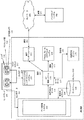
System Description FIG. 1 is a block diagram illustrating an
センサアレイ105によってキャプチャされたセンサデータ107は、AV100の車載データ処理システム110によって処理され得る。データ処理システム110は、道路交通を通って特定の目的地まで移動するために、AV100のサブマップデータベース130に格納されているサブマップ133を、センサデータ107と比較するために用い得る。サブマップ133は、AV100が道路交通を通って動作中に、データ処理システム110がリアルタイムのセンサデータ107と比較し得る所与の領域についての予め記録された表面データを含み得る。例えば、データ処理システム110は、AVの100が走行中の現在のルートの記録された3次元LiDARデータおよび3次元立体視データを含むデータベース130からの、現在のサブマップ134を用い得る。データ処理システム110は、センサデータ107を現在のサブマップ134の3次元LiDARデータおよび立体視データと連続的に比較して、潜在的な危険(例えば、歩行者、他の車両、自転車運転者等)を識別し得る。
The sensor data 107 captured by the sensor array 105 can be processed by the in-vehicle
車載データ処理システム110は、処理されたデータ113を、AV100のアクセル、ブレーキ、およびステアリングシステム125を操作し得るAV制御システム120に供給し得る。図1に示されている例では、説明の目的で、AV制御システム120はデータ処理システム110とは別のシステムとして示されている。AV制御システム120は、AV100の車載データ処理システム110の1以上の処理リソースとして含まれ得る。
The in-vehicle
特定の態様において、AV制御システム120には、AVのユーザから、または所与の領域を通るAVの車隊を管理するバックエンドシステム190から、目的地123が供給され得る。例えば、AV100は、1以上のネットワーク185を介して、バックエンドシステム190との通信162を送受信し得る。これらの通信162は、輸送を求めて要求しているユーザのための輸送要求を容易にするための、バックエンドシステム190からの輸送コマンドを含み得る。通信162は、位置の更新、状況の更新、ルート情報、乗車位置および降車位置データ等も含み得る。AV100の操作に関して、バックエンドシステム190またはAV100の乗客は、特定の目的地123を指定し得る。AV100の現在位置および目的地123を用いて、AV制御システム120は、特定の目的地123に向かう現在のルートに沿ってアクセル、ブレーキ、およびステアリングシステム125を操作するためのルートデータ177を受信するために、地図作成エンジン175を用い得る。同時に、AV制御システム120は、より差し迫った懸念(例えば、交通信号、道路条件、道路交通、歩行者活動、潜在的な危険等)に反応するために、データ処理システム110から処理されたセンサデータ110を受信し得る。従って、AV制御システム120は、ルートデータ177を用いてAV100を目的地123まで運転するために、アクセル、ブレーキ、およびステアリングシステム125に対する高レベル制御コマンド121を生成して実行し得る。更に、AV制御システム120は、データ処理システム110によって識別された差し迫った懸念に反応するために、アクセル、ブレーキ、およびステアリングシステム125に対する低レベルの、より緊急の制御コマンド121を生成して実行し得る。
In certain aspects, the
本明細書に記載される例によれば、車載データ処理システム110は、センサデータ107の品質を最大化する場合に、センサアレイ105からのセンサデータ107を処理する上で最大に効果的である。具体的には、データ処理システム110は、例えば、センサアレイ105の立体視カメラ112から受信されたカメラデータ109内の点光源をフィルタリングして除去することを試みる不必要な処理リソースを費やし得る。本明細書に記載される例によれば、センサアレイ105の各カメラシステム(例えば、立体視カメラ112)は、AV100のインテリジェントなレンズマスキングシステム135によって制御され得るマスキング層114を有し得るレンズ118を含む。
According to the example described herein, the in-vehicle
インテリジェントなレンズマスキングシステム135は、センサアレイ105のカメラシステムからリアルタイムのカメラデータ109を受信し得る。各カメラ(例えば、立体視カメラ112の各カメラ)について、インテリジェントなレンズマスキングシステム135は、光源(および/または各カメラに関する光源の位置)を識別して、光源を遮断するために各レンズのマスキング層114の幾つかの画素をアクティブ化するためのマスクコマンド137を生成し得る。特定の例では、各レンズ118についてのマスキング層114は、任意の数の画素を有するマトリクスとして構成され得る。インテリジェントなレンズマスキングシステム135は、マスキング層114を表すマトリクス上における点光源に対応する中心位置を識別して、各光源についての角サイズを測定し得る。従って、インテリジェントなレンズマスキングシステム135は、光源を遮断するために、(i)立体視カメラ112の視野内における点光源の識別された座標、および(ii)各光源の測定されたサイズに基づいて、マスキング層114の画素をアクティブ化するためのマスキングコマンド137を生成し得る。
The intelligent
更に、インテリジェントなレンズマスキングシステム135は、AV100が現在のルートに沿った運転を継続している際に、立体視カメラ112の各レンズ118の視野にわたって光源を追跡し得る。従って、インテリジェントなレンズマスキングシステム135は、光源が立体視カメラ112の視野内に留まっている間、それらの光源が連続的に遮断されるように、マスキング層の画素をアクティブ化および非アクティブ化し得る。
In addition, the intelligent
AV100は、AV100の状況的環境を連続的に記録する幾つかのカメラシステムを含み得る。例えば、AV100は、AV100の屋根上に立体視カメラアレイを含み得るものであり、立体視カメラアレイは、AV100の周辺の360°の視界を有するリアルタイムのデータを記録し得る。更に、AV100は、サイドミラー上、バンパー上、車体内に統合された、および/または客室内に、様々なカメラおよび/または立体視カメラ112を含み得る。任意の数のこれらのカメラは、動的なマスキングを行うためにAV100の全てのカメラの視野をモニタリングし得るインテリジェントなレンズマスキングシステム135に動作可能に結合されたマスキング層114を含み得る。以下、図2に関して、インテリジェントなレンズマスキングシステム135を更に説明する。
図2は、AV100のセンサアレイ105と関連して用いられる例示的なインテリジェントなレンズマスキングシステム200を示すブロック図である。図2に関して記載される例では、インテリジェントなレンズマスキングシステム200は、例えば、図1に関して図示されると共に記載されるインテリジェントな間レンズマスキングシステム135等の、AV100の構成要素として実装され得る。更に、説明のために、図2に示されているインテリジェントなレンズマスキングシステム200は、図1に関して図示されると共に記載されるセンサアレイ105の各単一の立体視カメラ210上で動作する。しかし、本明細書に記載される例によれば、インテリジェントなレンズマスキングシステム200は、AV100の車載データ処理システム110によって処理されるリアルタイムのセンサデータ107(例えば、センサデータ107に含まれるカメラデータ218)を供給する任意の数のカメラシステム上で動作し得る。
FIG. 2 is a block diagram illustrating an exemplary intelligent lens masking system 200 used in connection with the sensor array 105 of the
図2を参照すると、インテリジェントなレンズマスキングシステム200は、AV100のスタンドアロンのシステムとして動作してもよく、または、AV100の1以上のサブシステム(例えば、データ処理システム110等)に統合されてもよい。多くの態様において、インテリジェントなレンズマスキングシステム200は、立体視カメラ210からリアルタイムのカメラデータ218を受信し得る光源識別器205を含み得る。光源識別器205は、カメラデータ218を解析して、立体視カメラ210の各レンズの視野内の光源を識別し得る。例えば、光源識別器205は、立体視カメラ210の視野内の太陽290、街灯280、および/または太陽光を反射する建物230に対応する光源を識別し得る。カメラデータ218の品質に対して負の影響を有し得る光の点と同じまたは類似の特性を有する任意の数の光源が識別され得る。
Referring to FIG. 2, intelligent lens masking system 200 may operate as a stand-alone system of
幾つかの態様において、光源識別器205は、特定の光源の輝度が所定の閾値を超えるか否かを決定し得る。例えば、光源識別器は、視野内の各光源の(例えば、ルーメンまたはルクスの単位の)視覚的輝度を測定して、個々の光源の輝度が所定の値(例えば、閾値のルーメン値)を超えるか否かを決定し得る。この閾値は、光源がカメラデータ218の品質に対して有する影響と相関され得る。従って、太陽290からの直接光線292の輝度が閾値を超える場合には、光源識別器205は、カメラ識別子206および光点座標208をコマンド生成器215に供給し、それに従って、コマンド生成器215は、太陽290からの直接光線292を遮断するためのマスクコマンド217を生成し得る。
In some aspects, the light source identifier 205 may determine whether the brightness of a particular light source exceeds a predetermined threshold. For example, the light source identifier measures the visual luminance (eg, in lumens or lux) of each light source in the field of view, and the individual light source luminance exceeds a predetermined value (eg, a threshold lumen value). Or not. This threshold may be correlated with the effect that the light source has on the quality of the camera data 218. Thus, if the brightness of the direct ray 292 from the
インテリジェントなレンズマスキングシステム200はマスキングコントローラ250を含み得るものであり、マスキングコントローラ250は、マスクコマンド217を処理し、電圧信号252を生成して、光点座標208において識別された特定の画素に送信し得る。電圧信号252は、太陽290からの直接光線292が立体視カメラ210に入射しないよう遮断し得る幾つかの遮断画素294を生じるために、レンズのマスキング層212上の指定されている画素をアクティブ化し得る。従って、光源識別器205によって所定の輝度閾値を超えると決定された光源(例えば、太陽290)については、マスキングコントローラ250は、これらの光源からの光線が立体視カメラ210に入射しないよう完全に遮断できる指定されている電圧信号252を生成し得る。
The intelligent lens masking system 200 can include a masking
変形例において、マスキングコントローラ250は、マスキング層212の画素を、電圧信号252の電圧に応じて非常に明るいグレーから暗いグレー、黒までの可変グレースケールに沿ってアクティブ化させる、可変電圧信号252を生成し得る。特定の実装例によれば、光源識別器205は、最小閾値より高いそれぞれの輝度を有する様々な光源の光点座標208を識別し得る。従って、光源識別器205は、各光源についての輝度値209を測定し、輝度値209は、コマンド生成器215によって、各光源についての対応するマスクコマンド217を生成するために処理され得る。
In a variant, the masking
輝度値209に基づいて、コマンド生成器215は、マスキングコントローラ250に適切な電圧信号252を生成させるためのマスクコマンド217を生成し得る。電圧信号252は、カメラ識別子206に基づいて正しいカメラレンズに送信され得ると共に、指定されているレンズについての光点座標208に基づいてマスキング層212上の指定されている画素に送信され得る。更に、マスキングコントローラ250によって生成される電圧信号252は、光源識別器205によって測定された輝度値209に基づく電圧を有し得る。従って、電圧信号252は、指定されている画素に、その特定の光源について記録された輝度値209に基づいてスライドするグレースケールに従って、光源をフィルタリングまたは遮断させる。
Based on the
本明細書に記載される例に加えて、コマンド生成器215は、コマンド生成器215によって生成されるマスキングコマンド217が光源全体を正確に包含するように、光点座標208を用いて各光源の角サイズおよび形状または角直径を測定し得る。更に、各光源について、コマンド生成器215は、その光源についてアクティブ化される各画素についてのグレースケール値を指定するマスクコマンド217を生成し得る。従って、コマンド生成器215は、光源にわたってグレースケールの勾配を生じるマスクコマンド217を生成し得る。例えば、太陽290の直接光線292についての遮断画素294は、光源の中心に黒い画素、太陽290の直近の周囲に暗いグレー画素、および太陽290から外に向かって延びるより明るいグレー画素を含み得る。そのようなグレースケール勾配は、コマンド生成器215によって、任意の光源について、輝度値209および光点座標208に基づいて動的に算出されて実装され得る。
In addition to the examples described herein, the command generator 215 uses the light spot coordinates 208 so that the masking
多くの態様において、各光源についての光点座標208は、インテリジェントなレンズマスキングシステム200の追跡エンジン225によって追跡され得る。光源識別器205によって識別されたら、追跡エンジン225は、リアルタイムのカメラデータ218および/または初期光点座標208を受信して、立体視カメラ210の各レンズの視野にわたって各光源を追跡し得る。追跡エンジン225は、コマンド生成器215に光点座標208を動的に供給し、コマンド生成器215は、光源が視野内に留まっている間、それらの光源を連続的に遮断するために、更新されたマスクコマンド217を動的に生成し得る。
In many aspects, the light spot coordinates 208 for each light source can be tracked by the
一例として、立体視カメラ210の左側のレンズの視野は、建物230から反射された太陽光の光線232の影響を受け得る。リアルタイムのカメラデータ218は、反射光線232を光源識別器205に対して示し、光源識別器205は、立体視カメラ210および/または立体視カメラ210のレンズを示すカメラID206並びに反射光線232についての光点座標208をコマンド生成器215に供給し得る。コマンド生成器215は、反射光線232の角サイズおよび形状を測定して、反射光線が立体視カメラ210の左側のレンズの視野内にある間に反射光線232を遮断するために、特定の遮断画素234およびそれらの画素234についての電圧を示すマスクコマンド217を生成し得る。
As an example, the field of view of the left lens of the
幾つかの態様において、マスクコマンド217においてコマンド生成器215によって指定されている画素234は完全に遮断されてもよく、マスキングコントローラ250に、その画素を完全にアクティブ化する(例えば、その画素を黒くする)電圧信号252を生成させるものであってもよい。そのような実装例では、マスキングコントローラ250は、レンズのマスキング層212を二値で操作し得る。即ち、画素234は完全にアクティブ化されるか、または透明なままであり得る。従って、追跡エンジン225は、反射光線232がレンズの視野にわたって横断する際に、反射光線232を追跡し、コマンド生成器215は、反射光線が立体視カメラ210の視野内にある間、反射光線232を完全に遮断するためのマスクコマンド217を動的に生成し得る。
In some aspects, the
変形例において、マスクコマンド217においてコマンド生成器215によって指定されている画素234は、光源識別器205によって測定された輝度値209に従ってグレースケール化され得る。従って、コマンド生成器215は、グレースケール化された電圧信号252を用いてマスキング層212に反射光線232をフィルタリングおよび遮断させるマスクコマンド217を生成し得る。具体的には、マスキングコントローラ250は、より低い輝度値209を有する反射光線の画素234については、より低い電圧信号252を生成し得る(より明るいグレー画素をアクティブ化し得る)と共に、より高い輝度値209を有する反射光線の画素234については、より高い電圧信号252を生成し得る。反射光線232の相対的な輝度および形状に基づき、遮断画素234はそれに従って部分的にまたは完全にアクティブ化され、AV100が移動する際に反射光線232と相関してマスキング層を横断する。
In a variation, the
図2は、説明の目的で、太陽290からの直接光線292および街灯280からの光線282である2つの別個の光線の影響を受ける立体視カメラ210の右側のレンズも示している。各光線292、282は、光源識別器205によって識別され、光源識別器205は、追跡エンジン225およびコマンド生成器215に光点座標208を供給し得る。追跡エンジン225は、レンズの視野にわたって各光線292、282を追跡し、コマンド生成器215のために光点座標208を動的に更新し得る。コマンド生成器215は、座標208に基づいてマスクコマンド217を生成し、マスクコマンド217は、マスキングコントローラ250によって、直接光線292に対する遮断画素294および光線282に対する遮断画素284をアクティブ化するために実行され得る。
FIG. 2 also shows, for illustrative purposes, the right lens of the
従って、直接光線292および光線282の両方が立体視カメラ210の右側のレンズを横断する際、マスキングコントローラ250は、直接光線292および光線282が右側のレンズの視野内にある間、直接光線292および光線282を連続的に遮断するために、応答的な電圧信号252を動的に生成して、追跡されている光点座標208によって示される画素に送信し得る。本明細書において述べたように、遮断画素294、284は、二値の実装例では完全にアクティブ化され、または、グレースケールの実装例では、光源識別器205によって測定された輝度値209に基づいてグレースケールでアクティブ化され得る。
Thus, as both direct ray 292 and
図2の議論において、インテリジェントなレンズマスキングシステム200は、AV100が任意の所与のルートに沿って移動する際に、光源の即座のまたはほぼ即座の動的なマスキングを行い得る。二値の態様では、マスキングコントローラ250は、指定されている遮断画素をアクティブ化するために同じ電圧信号252を生成し得る。グレースケールの態様では、マスキングコントローラ250は、光源を包含する複数の画素にわたる相対的な輝度および/または輝度勾配に基づいて様々な電圧信号252を生成し得る。更に、コマンド生成器215は、光源識別器205によって測定された輝度値209に基づいて光源の角サイズおよび形状を決定し、それに従って光源を遮断するために、マスキングコントローラ250に、対応する画素についての対応する電圧信号252を生成させ得る。電圧信号252は、遮断画素234、284、294についてのグレースケール化された勾配(例えば、中心により高い輝度値209およびそれに従ってより高い電圧信号値252を有する太陽290については、点勾配(point gradient))を生じ得る。従って、AV100の車載データ処理システム110のデータ品質に負の影響を及ぼす光源が先制して遮断され、それにより、処理要件が低減され、AV100の動作フローが高められる。
In the discussion of FIG. 2, the intelligent lens masking system 200 may provide immediate or near instantaneous dynamic masking of the light source as the
方法論
図3は、AV100のカメラシステムのために光源を動的にマスキングする例示的な方法を説明する高レベルフローチャートである。以下の図3の説明では、図1に示されている同様の特徴を表している参照符号が参照され得る。更に、図3に関して説明される高レベル処理は、図1に関して説明される例示的なインテリジェントなレンズマスキングシステム135または図2に関して説明されるインテリジェントなレンズマスキングシステム200によって行われ得る。図3を参照すると、インテリジェントなレンズマスキングシステム135は、リアルタイムのカメラデータ109内において光源を動的に識別し得る(300)。光源は、太陽(302)(例えば、直接的な太陽光、反射された太陽光、または雲を通して拡散された太陽光)または人工光源(304)(例えば、ヘッドライト、緊急車輌のライト、街灯、スタジアムのライト、道路建設のライト等)に対応し得る。
Methodology FIG. 3 is a high-level flowchart illustrating an exemplary method for dynamically masking a light source for an
多くの態様において、インテリジェントなレンズマスキングシステム135は、光源によって影響されるカメラアレイ105内のカメラを識別し得る(305)。各カメラ(またはその中のカメラレンズ)について、インテリジェントなレンズマスキングシステム135は、各光源についての視野座標を決定し得る(310)。視野座標を用いて、インテリジェントなレンズマスキングシステム135は、カメラのレンズのマスキング層上の遮断画素をアクティブおよび非アクティブにすることにより、カメラについて各光源を動的に遮断し得る(315)。インテリジェントなレンズマスキングシステム135は、AV100が所与の領域を通って移動する際に通過する任意の数の光源について、図3に関して説明される処理を連続的に行い得る。更に、各光源について、インテリジェントなレンズマスキングシステム135は、視野に入った光源を直ちに識別して、その光源が特定のレンズの視野内にある間、その光源を遮断するために対応する画素をアクティブ化し得る。
In many aspects, the intelligent
図4は、AV100のカメラシステムのために光源を動的にマスキングする例示的な方法を説明する低レベルフローチャートである。以下の図4の説明では、図1に示されている同様の特徴を表している参照符号が参照され得る。更に、図4に関して説明される低レベル処理は、図1に関して説明される例示的なインテリジェントなレンズマスキングシステム135または図2に関して説明されるインテリジェントなレンズマスキングシステム200によって行われ得る。図4を参照すると、インテリジェントなレンズマスキングシステム135は、AV100のカメラアレイ105内の各カメラの各レンズの視野内にある光源を動的に識別し得る(400)。本明細書において述べたように、カメラは、個々のカメラ、複数のレンズを有する立体視カメラ112、赤外線カメラ、または紫外線カメラ(例えば、UV反射イメージング装置)であり得る。
FIG. 4 is a low-level flowchart illustrating an exemplary method for dynamically masking a light source for the
多くの例において、インテリジェントなレンズマスキングシステム135は、各カメラについて、各光源の相対的な角サイズおよび形状を測定し得る(405)。更に、インテリジェントなレンズマスキングシステム135は、各レンズの視野内にある各光源についての座標を決定し得る(410)。この座標は、視野内における各光源の境界、または各光源についての中心位置を正確に示し得る。幾つかの態様において、インテリジェントなレンズマスキングシステム135は、マスキング層の各画素についての、または光源に対応する対象の各画素についての輝度値も測定し得る(415)。例えば、インテリジェントなレンズマスキングシステム135は、光源についての輝度値のマトリクスを生成し得る。
In many examples, the intelligent
多くの例によれば、インテリジェントなレンズマスキングシステム135は、光源についての全体的な輝度が所定の閾値を超えるか否かを決定し得る(420)。例えば、インテリジェントなレンズマスキングシステム135は、輝度が、マスキング層上における光源の二値マスキングをトリガする最小閾値を超えるか否かを決定し得る。別の例として、インテリジェントなレンズマスキングシステム135は、生成された輝度値マトリクスの各画素が最小閾値輝度を超えるか否かを決定し得る。本明細書に記載されるように、最小閾値は、データ品質に対する影響と相関され得る。特定の光源については、データ品質に対する影響は最小であり得る(即ち、閾値輝度より低く測定され得る(422))ので、カメラレンズ上において光源をマスキングする必要はない。そのような光源、または光源に対応する個々の画素については、インテリジェントなレンズマスキングシステム135は、その光源を無視して、レンズの視野内における光源の動的な識別を継続し得る(400)。
According to many examples, intelligent
しかし、光源が閾値輝度を超える場合には(424)、インテリジェントなレンズマスキングシステム135は、影響される各カメラについて光源を遮断するために、指定されているマスキング層の画素をアクティブ化し得る(425)。インテリジェントなレンズマスキングシステム135は、最小輝度閾値を超える任意の数の検出された光源について、そのような能動的なマスキングを行い得る。更に、幾つかの例では、インテリジェントなレンズマスキングシステム135は、光源を正確に遮断するために対応する画素を完全にアクティブ化する二値マスキングを行い得る(427)。他の例では、インテリジェントなレンズマスキングシステム135は、測定された輝度値に基づいて(例えば、生成された輝度値マトリクスに従って)特定の画素をグレースケール化することによってグレースケール勾配を生じるグレースケールマスキングを行い得る(429)。
However, if the light source exceeds the threshold brightness (424), the intelligent
従って、インテリジェントなレンズマスキングシステム135は、光源が特定のレンズの視野内に留まっている間、その光源を遮断するために、適切な電圧信号を生成して各マスキング層114に送信し得る(430)。幾つかの態様において、マスキング層は透明なLCDディスプレイ層で構成され、従って、インテリジェントなレンズマスキングシステム135は、LCDディスプレイ層の指定されている画素をアクティブ化し得るか、または別様で、LCDディスプレイ層の指定されている画素に対する適切な電圧信号を生成し得る(435)。
Thus, the intelligent
多くの例において、インテリジェントなレンズマスキングシステム135は、AV100が所与の領域を通って移動する際に、AV100の各カメラの視野にわたって各光源を追跡し得る(440)。インテリジェントなレンズマスキングシステム135は、AV100上の各カメラのレンズの視野内にある各光源について、その光源が特定のレンズの視野内に留まっているか否かを決定し得る(445)。肯定された場合には(447)、インテリジェントなレンズマスキングシステム135は、その視野にわたってその光源の追跡を継続し得る(440)。しかし、その光源が特定のレンズの視野から出た場合には(449)、インテリジェントなレンズマスキングシステムは、その特定のレンズについてのマスキング層を非アクティブ化し得る(450)。インテリジェントなレンズマスキングシステム135は、各カメラの視野にわたって同じ光源および/または他の光源の追跡を継続し得る(455)。本明細書において示されるように、インテリジェントなレンズマスキングシステム135は、光源を連続的に遮断するために、各カメラのそれぞれのマスキング層上の画素を動的にアクティブ化および非アクティブ化し(460)、AV100のカメラの視野内にある光源の識別を動的に継続し得る(400)。
In many examples, the intelligent
ハードウェア図
図5は、本明細書に記載される例が実装され得るコンピュータシステム500を示すブロック図である。コンピュータシステム500は、例えば、1台のサーバまたは複数のサーバの組合せ上で実装され得る。例えば、コンピュータシステム500は、図1および図2に関して図示されると共に記載されるインテリジェントなレンズマスキングシステム135または200として実装され得る。特定の態様において、インテリジェントなレンズマスキングシステム200の機能は、図1に関して図示すると共に説明されるように、AV100の車載データ処理システム110の一部として実装され得るものであり、車載データ処理システム110そのものが、図5に示されているコンピュータシステム500によって表され得る。また、インテリジェントなレンズマスキングシステム200は、図5に関連して記載されるように、スタンドアロンのシステムまたは複数のコンピュータシステム500の組合せを用いて実装され得る。
Hardware Diagram FIG . 5 is a block diagram that illustrates a
1つの実装例において、コンピュータシステム500は、処理リソース510、主メモリ520、読み出し専用メモリ(ROM)530、ストレージ装置540、およびアレイインターフェース550を含む。コンピュータシステム500は、プロセッサ510によって実行可能な情報および指示を格納するための、例えば、ランダムアクセスメモリ(RAM)または他の動的ストレージ装置等によって設けられる主メモリ520に格納されている情報を処理するための少なくとも1つのプロセッサ510を含む。主メモリ520は、プロセッサ510によって実行される指示の実行中に、一時変数または他の中間情報を格納するためにも用いられ得る。コンピュータシステム500は、プロセッサ510のための静的な情報および指示を格納するためのROM530または他の静的ストレージ装置も含み得る。情報および指示を格納するために、例えば磁気ディスクまたは光ディスク等のストレージ装置540が設けられる。
In one implementation, the
アレイインターフェース550は、コンピュータシステム500が、無線電子リンクまたは有線インターフェース(例えば、内部バスおよび/もしくは外部バス等)を用いてカメラアレイ580の構成要素(例えば、マスキング層114)と通信するのを可能にする。複数の例によれば、コンピュータシステム500は、AV100のセンサアレイ105を介してリアルタイムのカメラデータ582を受信する。メモリ530に格納されている実行可能な指示は、AV100のカメラシステムの視野内にある光源を能動的に遮断するために、プロセッサ510が1組のマスクコマンド554を決定して実行するために実行するマスキング指示522を含み得る。
The
プロセッサ510は、図1〜図4に関連して説明したような実装例と共に説明された、および本願のどこかに記載されている、1以上の処理、ステップ、および他の機能を行うためのソフトウェアおよび/または他の論値を有するよう構成される。
The
本明細書に記載される例は、本明細書に記載される技術を実装するためのコンピュータシステム500の使用に関する。一例によれば、これらの技術は、コンピュータシステム500によって、主メモリ520に収容されている1以上の指示の1以上のシーケンスをプロセッサ510が実行することに応答して行われる。そのような指示は、別の機械可読媒体(例えば、ストレージ装置540等)から主メモリ520に読み込まれ得る。主メモリ520に収容されている指示のシーケンスの実行は、プロセッサ510に、本明細書に記載されている処理工程を行わせる。別の実装例では、本明細書に記載された例を実装するために、ソフトウェア指示の代わりに、またはそれと組み合わせて、配線された回路が用いられ得る。従って、記載された例は、ハードウェア回路およびソフトウェアのいかなる具体的な組合せにも限定されない。
The examples described herein relate to the use of
本明細書に記載されている例は、本明細書に記載されている他の概念、アイデア、またはシステムから独立して、本明細書に記載されている個々の要素および概念にまで及ぶと共に、例えば、本願のどこかに記載されている要素の組合せを含むことが意図される。本明細書には、添付の図面を参照して複数の例が詳細に記載されているが、本概念は、それらの正確な例に限定されないことを理解されたい。従って、当業者には多くの変形および変更が自明である。従って、本概念の範囲は、添付の特許請求の範囲およびそれらの等価物によって定められることが意図される。更に、個々にまたは例の一部として記載された特定の特徴は、たとえ他の特徴および例が、その特定の特徴に言及していなくても、他の個々に記載された特徴、または他の例の一部と組み合わされ得ることが意図される。従って、組合せが記載されていないことによって、そのような組合せに対する権利を主張することが除外されるべきではない。 Examples described herein extend to the individual elements and concepts described herein, independent of other concepts, ideas, or systems described herein, For example, it is intended to include combinations of elements described elsewhere in this application. Although the specification describes in detail several examples with reference to the accompanying drawings, it should be understood that the concept is not limited to these exact examples. Accordingly, many variations and modifications will be apparent to practitioners skilled in this art. Accordingly, the scope of the concept is intended to be defined by the appended claims and their equivalents. Further, particular features described individually or as part of an example may include other individually described features, or other features, even if other features and examples do not refer to that particular feature. It is intended that it can be combined with some of the examples. Accordingly, claiming a right to such a combination should not be excluded by the fact that the combination is not described.
100 自律走行車(AV)
105 センサアレイ
107 センサデータ
109、218 リアルタイムのカメラデータ
110 データ処理システム
112、210 立体視カメラ
114、212 マスキング層
118 レンズ
120 AV制御システム
135、200 インテリジェントなレンズマスキングシステム
137、217 マスクコマンド
205 光源識別器
208 光点座標
215 コマンド生成器
225 追跡エンジン
250 マスキングコントローラ
252 電圧信号
294 遮断画素
100 autonomous vehicles (AV)
105 Sensor array 107
Claims (20)
前記自律走行車が所与のルートに沿って移動する際に、前記カメラアレイからリアルタイムのデータを受信するアレイインターフェースと、
1以上のプロセッサと、
指示を格納した1以上のメモリリソースであって、前記1以上のプロセッサによって前記指示が実行された際に、前記インテリジェントなレンズマスキングシステムに、
前記リアルタイムのデータに基づいて、前記カメラアレイ内の、各カメラのレンズがマスキング層を有する各カメラについて、1以上の光源を動的に識別することと、
前記マスキング層の幾つかの画素をアクティブにすることにより、各前記カメラについて前記1以上の光源のうちの各光源を動的に遮断することと
を行わせる指示を格納した1以上のメモリリソースと
を含むことを特徴とするインテリジェントなレンズマスキングシステム。 An intelligent lens masking system for camera arrays of autonomous vehicles,
An array interface for receiving real-time data from the camera array as the autonomous vehicle moves along a given route;
One or more processors;
One or more memory resources storing instructions, wherein when the instructions are executed by the one or more processors, the intelligent lens masking system includes:
Dynamically identifying one or more light sources for each camera in the camera array where each camera lens has a masking layer based on the real-time data;
One or more memory resources storing instructions to activate each pixel of the one or more light sources for each of the cameras by activating some pixels of the masking layer; Intelligent lens masking system characterized by including
前記自律走行車が移動する際に、各前記カメラの視野内において、前記1以上の光源を追跡すること
を更に行わせる、請求項1記載のインテリジェントなレンズマスキングシステム。 The executed instructions are sent to the intelligent lens masking system,
The intelligent lens masking system of claim 1, further comprising tracking the one or more light sources within the field of view of each camera as the autonomous vehicle moves.
前記自律走行車が移動する際に、前記1以上の光源が各前記カメラの前記視野内に留まっている間、前記1以上の光源のうちの各光源を連続的に遮断するために、前記1以上の光源の追跡に基づいて、前記マスキング層の個々の画素を動的にアクティブ化および非アクティブ化すること
を更に行わせる、請求項2記載のインテリジェントなレンズマスキングシステム。 The executed instructions are sent to the intelligent lens masking system,
In order to continuously shut off each of the one or more light sources while the one or more light sources remain within the field of view of each of the cameras as the autonomous vehicle moves, The intelligent lens masking system of claim 2, further comprising dynamically activating and deactivating individual pixels of the masking layer based on the tracking of the light source.
前記画素に電圧を印加することによって、前記LCD層の前記画素をアクティブ化すること
を行わせる、請求項4記載のインテリジェントなレンズマスキングシステム。 The executed instructions are sent to the intelligent lens masking system,
The intelligent lens masking system of claim 4, wherein the pixel of the LCD layer is activated by applying a voltage to the pixel.
前記自律走行車の状況的環境を連続的に検出し、該状況的環境を示すリアルタイムのデータを生成するカメラアレイと、
前記リアルタイムのデータを、前記自律走行車が走行中の現在のルートの詳細な表面データを提供する格納されているサブマップと比較することにより、前記リアルタイムのデータを処理する車載データ処理システムと、
アクセル、ブレーキ、およびステアリングシステムと、
前記処理されたリアルタイムのデータを用いて、前記現在のルートに沿って前記アクセル、ブレーキ、およびステアリングシステムを操作する自律走行車制御システムと、
インテリジェントなレンズマスキングシステムであって、
前記リアルタイムのデータに基づいて、前記カメラアレイ内の、各カメラのレンズがマスキング層を有する各カメラについて、1以上の光源を動的に識別し、
前記マスキング層の幾つかの画素をアクティブにすることにより、各前記カメラについて前記1以上の光源のうちの各光源を動的に遮断する
インテリジェントなレンズマスキングシステムと
を含むことを特徴とする自律走行車。 In autonomous vehicles,
A camera array for continuously detecting the situational environment of the autonomous vehicle and generating real-time data indicating the situational environment;
An in-vehicle data processing system that processes the real-time data by comparing the real-time data with a stored submap that provides detailed surface data of the current route on which the autonomous vehicle is traveling;
An accelerator, brake, and steering system;
An autonomous vehicle control system for operating the accelerator, brake, and steering system along the current route using the processed real-time data;
An intelligent lens masking system,
Based on the real-time data, dynamically identify one or more light sources for each camera in the camera array where each camera lens has a masking layer;
An autonomous lens running system comprising: an intelligent lens masking system that dynamically blocks each of the one or more light sources for each of the cameras by activating several pixels of the masking layer car.
前記自律走行車のカメラアレイによって生成されたリアルタイムのデータに基づいて、前記カメラアレイ内の、各カメラのレンズがマスキング層を有する各カメラについて、1以上の光源を動的に識別することと、
前記マスキング層の幾つかの画素をアクティブにすることにより、各前記カメラについて前記1以上の光源のうちの各光源を動的に遮断することと
を行わせる指示を格納したことを特徴とする非一過性のコンピュータ可読媒体。 A non-transitory computer readable medium having instructions stored therein, wherein when the instructions are executed by one or more processors of an intelligent lens masking system of an autonomous vehicle, the intelligent lens masking system includes:
Dynamically identifying one or more light sources for each camera in which each camera lens has a masking layer based on real-time data generated by the camera array of the autonomous vehicle;
An instruction is stored that activates several pixels of the masking layer to dynamically shut off each of the one or more light sources for each of the cameras. Transient computer readable medium.
前記自律走行車が前記現在のルートに沿って移動する際に、前記リアルタイムのデータ内の各前記カメラの視野内において、前記1以上の光源を追跡すること
を更に行わせる、請求項17記載の非一過性のコンピュータ可読媒体。 The executed instructions are sent to the intelligent lens masking system,
18. The tracking of the one or more light sources within the field of view of each of the cameras in the real-time data as the autonomous vehicle moves along the current route. A non-transitory computer readable medium.
前記自律走行車が前記現在のルートに沿って移動する際に、前記1以上の光源が各前記カメラの前記視野内に留まっている間、前記1以上の光源のうちの各光源を連続的に遮断するために、前記1以上の光源の追跡に基づいて、前記マスキング層の個々の画素を動的にアクティブ化および非アクティブ化すること
を更に行わせる、請求項18記載の非一過性のコンピュータ可読媒体。 The executed instructions are sent to the intelligent lens masking system,
When the autonomous vehicle moves along the current route, each of the one or more light sources is continuously turned on while the one or more light sources remain in the field of view of each camera. 19. The non-transitory of claim 18, further comprising dynamically activating and deactivating individual pixels of the masking layer based on tracking of the one or more light sources for blocking. Computer readable medium.
Applications Claiming Priority (3)
| Application Number | Priority Date | Filing Date | Title |
|---|---|---|---|
| US14/979,351 US10048696B2 (en) | 2015-12-22 | 2015-12-22 | Intelligent lens masking system for an autonomous vehicle |
| US14/979,351 | 2015-12-22 | ||
| PCT/US2016/067821 WO2017112690A1 (en) | 2015-12-22 | 2016-12-20 | Intelligent lens masking system for an autonomous vehicle |
Publications (2)
| Publication Number | Publication Date |
|---|---|
| JP2019506781A true JP2019506781A (en) | 2019-03-07 |
| JP2019506781A5 JP2019506781A5 (en) | 2020-02-06 |
Family
ID=59064382
Family Applications (1)
| Application Number | Title | Priority Date | Filing Date |
|---|---|---|---|
| JP2018532386A Pending JP2019506781A (en) | 2015-12-22 | 2016-12-20 | Intelligent lens masking system for autonomous vehicles |
Country Status (6)
| Country | Link |
|---|---|
| US (2) | US10048696B2 (en) |
| EP (1) | EP3394694A4 (en) |
| JP (1) | JP2019506781A (en) |
| DE (1) | DE202016008771U1 (en) |
| IL (1) | IL260002B (en) |
| WO (1) | WO2017112690A1 (en) |
Families Citing this family (14)
| Publication number | Priority date | Publication date | Assignee | Title |
|---|---|---|---|---|
| US10048696B2 (en) | 2015-12-22 | 2018-08-14 | Uber Technologies, Inc. | Intelligent lens masking system for an autonomous vehicle |
| CN108322637B (en) * | 2017-01-17 | 2020-02-11 | 杭州海康威视数字技术股份有限公司 | Equipment protection method and device under strong light |
| US10558873B2 (en) * | 2017-12-14 | 2020-02-11 | Waymo Llc | Methods and systems for controlling extent of light encountered by an image capture device of a self-driving vehicle |
| US10921142B2 (en) * | 2017-12-14 | 2021-02-16 | Waymo Llc | Methods and systems for sun-aware vehicle routing |
| CN112188974B (en) * | 2018-05-09 | 2024-04-02 | 金泰克斯公司 | Switchable imager lens cover |
| US11082630B2 (en) * | 2019-03-13 | 2021-08-03 | Magna Electronics Inc. | Vehicular vision system using adaptive mask at camera |
| US11256013B2 (en) | 2019-03-27 | 2022-02-22 | Uatc, Llc | Dynamic matrix filter for vehicle image sensor |
| US11635326B2 (en) | 2019-04-02 | 2023-04-25 | Waymo Llc | Stray-light testing station |
| US10791324B1 (en) | 2019-04-17 | 2020-09-29 | Waymo Llc | On-car stray-light testing cart |
| CN110488688B (en) * | 2019-08-05 | 2022-03-29 | 华南理工大学 | Intelligent trolley advancing method and system based on fluorescence reaction and photosensitive sensor |
| US11938795B2 (en) | 2019-10-18 | 2024-03-26 | Magna Electronics Inc. | Vehicular vision system with glare reducing windshield |
| US11595559B2 (en) | 2020-09-23 | 2023-02-28 | Apple Inc. | Tamper-resistant indicators for electronic devices |
| US11636688B1 (en) | 2021-10-06 | 2023-04-25 | Ford Global Technologies, Llc | Enhanced vehicle operation |
| US20230226882A1 (en) * | 2022-01-18 | 2023-07-20 | Hyundai Motor Company | Solar load feedback for climate control |
Citations (2)
| Publication number | Priority date | Publication date | Assignee | Title |
|---|---|---|---|---|
| JPH09214827A (en) * | 1996-02-02 | 1997-08-15 | Mitsubishi Electric Corp | On-vehicle camera equipment |
| JP2007251258A (en) * | 2006-03-13 | 2007-09-27 | Fujitsu Ten Ltd | Image recognizing device |
Family Cites Families (25)
| Publication number | Priority date | Publication date | Assignee | Title |
|---|---|---|---|---|
| US7596242B2 (en) * | 1995-06-07 | 2009-09-29 | Automotive Technologies International, Inc. | Image processing for vehicular applications |
| US6685317B2 (en) * | 2000-06-13 | 2004-02-03 | Massie Research Laboratories, Inc. | Digital eye camera |
| US7016518B2 (en) * | 2002-03-15 | 2006-03-21 | Extreme Cctv Inc. | Vehicle license plate imaging and reading system for day and night |
| US7612803B2 (en) * | 2003-06-10 | 2009-11-03 | Zoran Corporation | Digital camera with reduced image buffer memory and minimal processing for recycling through a service center |
| US7548270B2 (en) * | 2005-09-08 | 2009-06-16 | Delphi Technologies, Inc. | Method of exposure control for an imaging system |
| KR20070069653A (en) | 2005-12-28 | 2007-07-03 | 주식회사 팬택앤큐리텔 | Apparatus and method for controlling auto exposure of digital camera |
| US8139109B2 (en) | 2006-06-19 | 2012-03-20 | Oshkosh Corporation | Vision system for an autonomous vehicle |
| US7973838B2 (en) * | 2006-07-07 | 2011-07-05 | Immersive Media Company | Active mask for electronic imaging system |
| JP4978214B2 (en) * | 2006-10-13 | 2012-07-18 | ソニー株式会社 | Imaging system and pixel defect correction apparatus |
| JP5141311B2 (en) | 2008-03-12 | 2013-02-13 | トヨタ自動車株式会社 | Vehicle control device |
| US8126642B2 (en) | 2008-10-24 | 2012-02-28 | Gray & Company, Inc. | Control and systems for autonomously driven vehicles |
| US8558940B2 (en) * | 2008-11-27 | 2013-10-15 | Nikon Corporation | Image sensor and image-capturing device |
| US8629389B2 (en) * | 2009-07-29 | 2014-01-14 | Geoffrey Louis Barrows | Low profile camera and vision sensor |
| KR101273620B1 (en) | 2011-11-24 | 2013-06-11 | 주식회사 한국 오.지.케이 | Depending on ambient illumination which automatically adjust transmittance of lens Goggles |
| CN103258339A (en) * | 2012-02-16 | 2013-08-21 | 克利特股份有限公司 | Real-time compositing of live recording-based and computer graphics-based media streams |
| US8949016B1 (en) * | 2012-09-28 | 2015-02-03 | Google Inc. | Systems and methods for determining whether a driving environment has changed |
| US9513119B2 (en) * | 2013-03-15 | 2016-12-06 | The United States Of America, As Represented By The Secretary Of The Navy | Device and method for multifunction relative alignment and sensing |
| US9323053B2 (en) * | 2013-09-30 | 2016-04-26 | Nghia Trong Lam | Active shielding against intense illumination (ASAII) system for direct viewing |
| KR101592409B1 (en) | 2014-05-21 | 2016-02-05 | (주)엠시스 | Picture quality enhancement apparatus, digital photographing apparatus with the same and picture quality enhancement method thereof |
| US9712741B2 (en) * | 2014-09-19 | 2017-07-18 | Be Topnotch, Llc | Smart vehicle sun visor |
| WO2016200792A1 (en) * | 2015-06-07 | 2016-12-15 | Barrows, Geoffrey, Louis | Localization method and apparatus |
| US9386230B1 (en) * | 2015-06-12 | 2016-07-05 | Google Inc. | Day and night detection based on one or more of illuminant detection, lux level detection, and tiling |
| US9749554B2 (en) * | 2015-08-20 | 2017-08-29 | Semiconductor Components Industries, Llc | Systems and methods for weighted image signal readout |
| US9952304B2 (en) * | 2015-09-10 | 2018-04-24 | Ford Global Technologies, Llc | Vehicle positioning system |
| US10048696B2 (en) * | 2015-12-22 | 2018-08-14 | Uber Technologies, Inc. | Intelligent lens masking system for an autonomous vehicle |
-
2015
- 2015-12-22 US US14/979,351 patent/US10048696B2/en active Active
-
2016
- 2016-12-20 EP EP16879983.1A patent/EP3394694A4/en not_active Withdrawn
- 2016-12-20 DE DE202016008771.2U patent/DE202016008771U1/en active Active
- 2016-12-20 JP JP2018532386A patent/JP2019506781A/en active Pending
- 2016-12-20 WO PCT/US2016/067821 patent/WO2017112690A1/en active Application Filing
-
2018
- 2018-06-13 IL IL260002A patent/IL260002B/en unknown
- 2018-06-26 US US16/018,246 patent/US10884271B2/en active Active
Patent Citations (2)
| Publication number | Priority date | Publication date | Assignee | Title |
|---|---|---|---|---|
| JPH09214827A (en) * | 1996-02-02 | 1997-08-15 | Mitsubishi Electric Corp | On-vehicle camera equipment |
| JP2007251258A (en) * | 2006-03-13 | 2007-09-27 | Fujitsu Ten Ltd | Image recognizing device |
Also Published As
| Publication number | Publication date |
|---|---|
| US20180299903A1 (en) | 2018-10-18 |
| US10048696B2 (en) | 2018-08-14 |
| US10884271B2 (en) | 2021-01-05 |
| US20170177000A1 (en) | 2017-06-22 |
| EP3394694A1 (en) | 2018-10-31 |
| DE202016008771U1 (en) | 2019-09-04 |
| EP3394694A4 (en) | 2018-10-31 |
| IL260002A (en) | 2018-10-31 |
| IL260002B (en) | 2021-10-31 |
| WO2017112690A1 (en) | 2017-06-29 |
Similar Documents
| Publication | Publication Date | Title |
|---|---|---|
| JP2019506781A (en) | Intelligent lens masking system for autonomous vehicles | |
| US10684361B2 (en) | Predictive sensor array configuration system for an autonomous vehicle | |
| US10712742B2 (en) | Predictive sensor array configuration system for an autonomous vehicle | |
| US10949679B2 (en) | Nighttime sensing | |
| WO2016179980A1 (en) | On-board projection method and system | |
| JP2019506781A5 (en) | ||
| US11328428B2 (en) | Technologies for detection of occlusions on a camera | |
| CN110335479A (en) | Virtual zebra stripes method for controlling projection, device and virtual zebra stripes optical projection system | |
| JP2015103894A (en) | On-vehicle image processing apparatus, and semiconductor device | |
| US11787331B2 (en) | Adaptive vehicle headlight | |
| US11902670B2 (en) | Auto exposure using multiple cameras and map prior information | |
| US11933599B2 (en) | Electronic device and method for controlling same | |
| US20220194187A1 (en) | Dimming light that is interfering with an observer's vision | |
| CN114007902A (en) | Head-up display device and head-up display method | |
| KR102614575B1 (en) | Display adjustment methods and devices, and systems and storage media | |
| KR102644294B1 (en) | Camera embedded system for multi-dimensional body sensing and ultra-compact wide-angle camera using the same | |
| KR102592860B1 (en) | Pedestrian detection device and detection method | |
| WO2022199416A1 (en) | Camera module, terminal device, and imaging method | |
| JP2023001977A (en) | Vehicle peripheral information display device, and vehicle peripheral information display method |
Legal Events
| Date | Code | Title | Description |
|---|---|---|---|
| RD03 | Notification of appointment of power of attorney |
Free format text: JAPANESE INTERMEDIATE CODE: A7423 Effective date: 20190516 |
|
| A521 | Request for written amendment filed |
Free format text: JAPANESE INTERMEDIATE CODE: A821 Effective date: 20190604 |
|
| RD04 | Notification of resignation of power of attorney |
Free format text: JAPANESE INTERMEDIATE CODE: A7424 Effective date: 20190604 |
|
| A521 | Request for written amendment filed |
Free format text: JAPANESE INTERMEDIATE CODE: A523 Effective date: 20191219 |
|
| A621 | Written request for application examination |
Free format text: JAPANESE INTERMEDIATE CODE: A621 Effective date: 20191219 |
|
| A871 | Explanation of circumstances concerning accelerated examination |
Free format text: JAPANESE INTERMEDIATE CODE: A871 Effective date: 20191219 |
|
| A711 | Notification of change in applicant |
Free format text: JAPANESE INTERMEDIATE CODE: A711 Effective date: 20200128 |
|
| A977 | Report on retrieval |
Free format text: JAPANESE INTERMEDIATE CODE: A971007 Effective date: 20200423 |
|
| A975 | Report on accelerated examination |
Free format text: JAPANESE INTERMEDIATE CODE: A971005 Effective date: 20200513 |
|
| A131 | Notification of reasons for refusal |
Free format text: JAPANESE INTERMEDIATE CODE: A131 Effective date: 20200529 |
|
| A601 | Written request for extension of time |
Free format text: JAPANESE INTERMEDIATE CODE: A601 Effective date: 20200828 |
|
| A02 | Decision of refusal |
Free format text: JAPANESE INTERMEDIATE CODE: A02 Effective date: 20201221 |