JP2019505437A - Power unit - Google Patents
Power unit Download PDFInfo
- Publication number
- JP2019505437A JP2019505437A JP2018540111A JP2018540111A JP2019505437A JP 2019505437 A JP2019505437 A JP 2019505437A JP 2018540111 A JP2018540111 A JP 2018540111A JP 2018540111 A JP2018540111 A JP 2018540111A JP 2019505437 A JP2019505437 A JP 2019505437A
- Authority
- JP
- Japan
- Prior art keywords
- power unit
- crankshaft
- cylinder head
- unit according
- camshaft
- Prior art date
- Legal status (The legal status is an assumption and is not a legal conclusion. Google has not performed a legal analysis and makes no representation as to the accuracy of the status listed.)
- Granted
Links
Images


Classifications
-
- F—MECHANICAL ENGINEERING; LIGHTING; HEATING; WEAPONS; BLASTING
- F02—COMBUSTION ENGINES; HOT-GAS OR COMBUSTION-PRODUCT ENGINE PLANTS
- F02B—INTERNAL-COMBUSTION PISTON ENGINES; COMBUSTION ENGINES IN GENERAL
- F02B75/00—Other engines
- F02B75/16—Engines characterised by number of cylinders, e.g. single-cylinder engines
- F02B75/18—Multi-cylinder engines
- F02B75/22—Multi-cylinder engines with cylinders in V, fan, or star arrangement
- F02B75/225—Multi-cylinder engines with cylinders in V, fan, or star arrangement having two or more crankshafts
-
- F—MECHANICAL ENGINEERING; LIGHTING; HEATING; WEAPONS; BLASTING
- F02—COMBUSTION ENGINES; HOT-GAS OR COMBUSTION-PRODUCT ENGINE PLANTS
- F02F—CYLINDERS, PISTONS OR CASINGS, FOR COMBUSTION ENGINES; ARRANGEMENTS OF SEALINGS IN COMBUSTION ENGINES
- F02F1/00—Cylinders; Cylinder heads
- F02F1/24—Cylinder heads
-
- F—MECHANICAL ENGINEERING; LIGHTING; HEATING; WEAPONS; BLASTING
- F02—COMBUSTION ENGINES; HOT-GAS OR COMBUSTION-PRODUCT ENGINE PLANTS
- F02B—INTERNAL-COMBUSTION PISTON ENGINES; COMBUSTION ENGINES IN GENERAL
- F02B63/00—Adaptations of engines for driving pumps, hand-held tools or electric generators; Portable combinations of engines with engine-driven devices
- F02B63/04—Adaptations of engines for driving pumps, hand-held tools or electric generators; Portable combinations of engines with engine-driven devices for electric generators
- F02B63/042—Rotating electric generators
-
- F—MECHANICAL ENGINEERING; LIGHTING; HEATING; WEAPONS; BLASTING
- F02—COMBUSTION ENGINES; HOT-GAS OR COMBUSTION-PRODUCT ENGINE PLANTS
- F02B—INTERNAL-COMBUSTION PISTON ENGINES; COMBUSTION ENGINES IN GENERAL
- F02B69/00—Internal-combustion engines convertible into other combustion-engine type, not provided for in F02B11/00; Internal-combustion engines of different types characterised by constructions facilitating use of same main engine-parts in different types
-
- F—MECHANICAL ENGINEERING; LIGHTING; HEATING; WEAPONS; BLASTING
- F02—COMBUSTION ENGINES; HOT-GAS OR COMBUSTION-PRODUCT ENGINE PLANTS
- F02B—INTERNAL-COMBUSTION PISTON ENGINES; COMBUSTION ENGINES IN GENERAL
- F02B75/00—Other engines
- F02B75/06—Engines with means for equalising torque
- F02B75/065—Engines with means for equalising torque with double connecting rods or crankshafts
-
- F—MECHANICAL ENGINEERING; LIGHTING; HEATING; WEAPONS; BLASTING
- F02—COMBUSTION ENGINES; HOT-GAS OR COMBUSTION-PRODUCT ENGINE PLANTS
- F02B—INTERNAL-COMBUSTION PISTON ENGINES; COMBUSTION ENGINES IN GENERAL
- F02B75/00—Other engines
- F02B75/16—Engines characterised by number of cylinders, e.g. single-cylinder engines
- F02B75/18—Multi-cylinder engines
- F02B75/22—Multi-cylinder engines with cylinders in V, fan, or star arrangement
- F02B75/228—Multi-cylinder engines with cylinders in V, fan, or star arrangement with cylinders arranged in parallel banks
-
- F—MECHANICAL ENGINEERING; LIGHTING; HEATING; WEAPONS; BLASTING
- F02—COMBUSTION ENGINES; HOT-GAS OR COMBUSTION-PRODUCT ENGINE PLANTS
- F02B—INTERNAL-COMBUSTION PISTON ENGINES; COMBUSTION ENGINES IN GENERAL
- F02B75/00—Other engines
- F02B75/16—Engines characterised by number of cylinders, e.g. single-cylinder engines
- F02B75/18—Multi-cylinder engines
- F02B2075/1804—Number of cylinders
- F02B2075/1808—Number of cylinders two
-
- F—MECHANICAL ENGINEERING; LIGHTING; HEATING; WEAPONS; BLASTING
- F02—COMBUSTION ENGINES; HOT-GAS OR COMBUSTION-PRODUCT ENGINE PLANTS
- F02B—INTERNAL-COMBUSTION PISTON ENGINES; COMBUSTION ENGINES IN GENERAL
- F02B2275/00—Other engines, components or details, not provided for in other groups of this subclass
- F02B2275/02—Attachment or mounting of cylinder heads on cylinders
Landscapes
- Engineering & Computer Science (AREA)
- Chemical & Material Sciences (AREA)
- Combustion & Propulsion (AREA)
- Mechanical Engineering (AREA)
- General Engineering & Computer Science (AREA)
- Hybrid Electric Vehicles (AREA)
- Valve Device For Special Equipments (AREA)
- Valve-Gear Or Valve Arrangements (AREA)
- Cylinder Crankcases Of Internal Combustion Engines (AREA)
- Control Of Vehicle Engines Or Engines For Specific Uses (AREA)
Abstract
本発明は、パワーユニット、特にハイブリッド車両のパワーユニットに関するものであって、クランク軸ハウジング(10)を備えた、2シリンダ往復ピストンエンジン(1)を有し、前記クランク軸ハウジング内に2つの逆方向のクランク軸(11、12)が配置されており、前記クランク軸がコネクティングロッド(13)によってピストン(18、19)と結合されており、前記ピストンが2つのシリンダ(21、22)内にタンデム配置で案内されており、少なくとも1つのクランク軸(11、12)がジェネレータ(41、42)と駆動結合されており、かつ往復ピストンエンジン(1)がシリンダヘッド(20)を有し、前記シリンダヘッドがクランク軸ハウジング(10)と結合されおり、往復ピストンエンジン(1)が下方に位置するカム軸(30)を有し、かつシリンダヘッド(20)が少なくとも2つの、特に互いに対して180°回動された位置において、クランク軸ハウジング(10)と結合可能である。さらに、本発明は、この種のパワーユニットを有する車両に関する。【選択図】図1dThe present invention relates to a power unit, particularly a hybrid vehicle power unit, which has a two-cylinder reciprocating piston engine (1) with a crankshaft housing (10), and has two opposite directions in the crankshaft housing. A crankshaft (11, 12) is arranged, the crankshaft is connected to a piston (18, 19) by a connecting rod (13), and the piston is arranged in tandem in two cylinders (21, 22). At least one crankshaft (11, 12) is drivingly coupled to the generator (41, 42), and the reciprocating piston engine (1) has a cylinder head (20), the cylinder head Is coupled to the crankshaft housing (10) and the reciprocating piston engine (1) is A position cam shaft (30), and a cylinder head (20) is at least two, in particular 180 ° rotation position relative to one another, can be coupled to the crankshaft housing (10). Furthermore, the present invention relates to a vehicle having such a power unit. [Selection] Figure 1d
Description
本発明は、パワーユニット、特にハイブリッド車両のパワーユニット及びこの種のパワーユニットを有する車両に関する。冒頭で挙げた種類のパワーユニットは、たとえば国際公開第2012/056257(A1)号パンフレットから知られている。 The present invention relates to a power unit, in particular a hybrid vehicle power unit and a vehicle having this type of power unit. A power unit of the type mentioned at the beginning is known, for example, from WO 2012/056257 (A1) pamphlet.
この既知のパワーユニットは、2つのピストンを備えた2シリンダ往復ピストンエンジンを有しており、そのピストンは2つのシリンダ内にタンデム配置で案内されている。各ピストンは、コネクティングロッドによってそれぞれのクランク軸と結合されている。2つのクランク軸は、逆方向に回転する。2シリンダ往復ピストンエンジンは、さらに、クランク軸ハウジングを有しており、その中にクランク軸が配置されている。さらにジェネレータが設けられており、それが少なくともクランク軸と駆動結合されている。クランク軸ハウジング上にシリンダヘッドが取り付けられており、そのシリンダヘッドがクランク軸ハウジングと堅固に結合されている。 This known power unit has a two-cylinder reciprocating piston engine with two pistons, which are guided in tandem arrangement in two cylinders. Each piston is connected to a respective crankshaft by a connecting rod. The two crankshafts rotate in opposite directions. The two-cylinder reciprocating piston engine further has a crankshaft housing in which the crankshaft is disposed. Furthermore, a generator is provided, which is drivingly connected to at least the crankshaft. A cylinder head is mounted on the crankshaft housing, and the cylinder head is firmly coupled to the crankshaft housing.
すでに知られているこのパワーユニットは、好ましくは、ハイブリッド車両内で使用される。この種のハイブリッド車両においては、エネルギ蓄積部材、特にアキュムレータのために、特に大きい組み込み空間が必要とされるので、パワーユニットの組み込み大きさを削減することが望まれる。また、車両内のパワーユニットの所望の組み込み場所も、考慮されなければならない。重量分配の理由からは、パワーユニットをエンジンルームの隔壁のできるだけ近傍に位置決めすることが、好ましい。その場合には、シリンダヘッドに接続されている排ガス導管又は空気供給導管がじゃまになることがあり得る。その限りにおいて、柔軟かつ場所をとらずに車両内へ組み込むことができる、パワーユニットが必要とされる。 This already known power unit is preferably used in a hybrid vehicle. In this type of hybrid vehicle, a particularly large installation space is required for the energy storage member, particularly the accumulator. Therefore, it is desired to reduce the installation size of the power unit. Also, the desired installation location of the power unit in the vehicle must be considered. For reasons of weight distribution, it is preferable to position the power unit as close as possible to the partition of the engine room. In that case, the exhaust gas conduit or the air supply conduit connected to the cylinder head can be obstructed. To that extent, there is a need for a power unit that is flexible and can be incorporated into a vehicle without taking up space.
これを背景として、本発明の課題は、冒頭で挙げた種類のパワーユニットを改良し、それによってパワーユニットを様々な組み込み状況において柔軟に挿入することができるようにすることである。本発明の他の課題は、この種のパワーユニットを有する車両を提供することである。 Against this background, the object of the present invention is to improve the power unit of the kind mentioned at the outset so that it can be inserted flexibly in various installation situations. Another object of the present invention is to provide a vehicle having this type of power unit.
本発明によれば、この課題は、パワーユニットに関しては、特許請求項1の対象によって解決される。車両に関しては、課題は、特許請求項11の対象によって解決される。 According to the invention, this problem is solved by the subject matter of claim 1 in terms of power units. With respect to the vehicle, the problem is solved by the subject matter of claim 11.
すなわち本発明は、クランク軸ハウジングを備えた2シリンダ往復ピストンエンジンを有するパワーユニット、特にハイブリッド車両のパワーユニットを提供する、という考えに基づいている。クランク軸ハウジング内には、2つの逆方向のクランク軸が配置されており、それらはコネクティングロッドによって2つのピストンと結合されている。ピストンは、2つのシリンダ内にタンデム配置で案内されている。少なくとも1つのクランク軸が、ジェネレータと駆動結合されている。往復ピストンエンジンがシリンダヘッドを有し、そのシリンダヘッドがクランク軸ハウジングと結合されている。往復ピストンエンジンは、好ましくは下方に位置するカム軸を有している。シリンダヘッドは、少なくとも2つの、特に互いに対して180°回動された位置において、クランク軸ハウジングと結合可能とすることができる。 That is, the present invention is based on the idea of providing a power unit having a two-cylinder reciprocating piston engine with a crankshaft housing, in particular a hybrid vehicle power unit. Two opposite crankshafts are arranged in the crankshaft housing and are connected to the two pistons by connecting rods. The piston is guided in tandem arrangement in two cylinders. At least one crankshaft is drivingly coupled with the generator. A reciprocating piston engine has a cylinder head that is coupled to a crankshaft housing. The reciprocating piston engine preferably has a camshaft located below. The cylinder head may be connectable to the crankshaft housing in at least two positions, in particular in a position rotated 180 ° relative to each other.
下方に位置するカム軸と、クランク軸ハウジングと結合可能なシリンダヘッドとからなる組み合わせは、特別な利点を有している。下方に位置するカム軸は、特にパワーユニットのための小さい組み立て大きさをもたらす。2つの異なる位置においてクランク軸ハウジングと結合可能なシリンダヘッドは、そのようにして車両内部のパワーユニットの配置を柔軟に構成できる限りにおいて、それに寄与する。したがってパワーユニットは、それぞれ組み込み状況に応じて、車両内でできる限り少ない組み込み空間しか必要としない。というのは、クランク軸ハウジングと異なるように結合可能なシリンダヘッドが、空気供給導管又は排ガス導管のためのそれに応じた導管ガイドを許すからである。 The combination of the camshaft located below and the cylinder head that can be coupled to the crankshaft housing has special advantages. The camshaft located below provides a small assembly size, especially for the power unit. A cylinder head that can be coupled to the crankshaft housing at two different positions contributes to this as long as the arrangement of the power units inside the vehicle can be configured flexibly. Therefore, each power unit requires as little installation space as possible in the vehicle, depending on the installation situation. This is because the cylinder head, which can be coupled differently from the crankshaft housing, allows a corresponding conduit guide for the air supply conduit or exhaust conduit.
たとえば、パワーユニットは、エンジンルーム内の隔壁の比較的近傍に位置決めすることができる。というのは、シリンダヘッドは、走行方向において吸気パイプ又は排気パイプがシリンダヘッドから前方へ張り出すように、方向づけすることができるからである。したがってエンジンルーム内に比較的大きい割合の提供可能な容積が残り、それを、たとえば蓄積部材のために利用することができる。その代わりに、パワーユニットを寝かせて配置する場合に、他の導管ガイドが好ましい場合もある。その限りにおいて、このパワーユニットは、シリンダヘッドが種々の位置においてクランク軸ハウジングと結合できることにより、柔軟に挿入することができる。 For example, the power unit can be positioned relatively close to the partition in the engine room. This is because the cylinder head can be oriented such that the intake pipe or the exhaust pipe projects forward from the cylinder head in the running direction. Thus, a relatively large proportion of the available volume remains in the engine room, which can be utilized, for example, for a storage member. Instead, other conduit guides may be preferred when the power unit is laid down. To that extent, the power unit can be inserted flexibly because the cylinder head can be coupled to the crankshaft housing at various positions.
特に好ましくは、シリンダヘッドは対称の構造を有している。具体的には、シリンダヘッド内及び/又はクランク軸ハウジング内の接続面もしくは接続開口部は、パワーユニットの中心軸線に対して軸対称に配置することができるので、クランク軸ハウジングに対するシリンダヘッドの方向づけが任意に選択可能となる。言い換えると、シリンダヘッドは2つの異なる方向づけで任意にクランク軸ハウジングと結合することができ、その場合に同時に、クランク軸ハウジングに対するシリンダヘッドの方向づけとは関係なく、それぞれの接続開口部は互いに合致する。 Particularly preferably, the cylinder head has a symmetrical structure. Specifically, since the connection surface or the connection opening in the cylinder head and / or the crankshaft housing can be arranged axisymmetrically with respect to the central axis of the power unit, the orientation of the cylinder head with respect to the crankshaft housing can be determined. It can be arbitrarily selected. In other words, the cylinder head can be arbitrarily coupled with the crankshaft housing in two different orientations, and at the same time, the respective connection openings coincide with each other irrespective of the orientation of the cylinder head relative to the crankshaft housing. .
本発明の好ましい形態において、カム軸はクランク軸の間の中心平面内に配置されている。特にカム軸は、ピストンのコネクティングロッドの間の中心平面内に配置することができる。したがってピストンのコネクティングロッドの間で提供可能なスペースが、特に効率的に利用され、それが、パワーユニットのコンパクト性を支援する。 In a preferred form of the invention, the camshaft is arranged in a central plane between the crankshafts. In particular, the camshaft can be arranged in a central plane between the connecting rods of the piston. The space that can be provided between the connecting rods of the piston is therefore used particularly efficiently, which helps the compactness of the power unit.
カム軸は、好ましくはピストンの下死点の下方に配置されている。これによって同様に、パワーユニットが特にコンパクトに構成される。特にピストンの間隔をつめることができ、コネクティングロッド又はシリンダがカム軸と衝突することはない。 The camshaft is preferably disposed below the bottom dead center of the piston. This likewise makes the power unit particularly compact. In particular, the distance between the pistons can be reduced, and the connecting rod or cylinder does not collide with the camshaft.
シリンダヘッドは、好ましくは、点火混合気のための吸気スリーブと排ガスのための排気スリーブとを有している。吸気スリーブと排気スリーブは、好ましくはシリンダヘッドの互いに逆となる側に配置されている。 The cylinder head preferably has an intake sleeve for the ignition mixture and an exhaust sleeve for the exhaust gas. The intake sleeve and the exhaust sleeve are preferably arranged on opposite sides of the cylinder head.
カム軸は、好ましくは、ベルトドライブ又はチェーンドライブを介してクランク軸の1つと駆動結合されている。カム軸は、好ましくは、少なくとも1つのカムを有することができ、そのカムが制御ロッドと結合されている。制御ロッドは、好ましくはシリンダヘッド内の弁のロッカーアームと作動的に結合されている。制御ロッドは、カムの外側輪郭をロッカーアームの傾き運動へ伝達するので、シリンダヘッド内の弁はカム輪郭を用いて開放し、かつ閉鎖することができる。 The camshaft is preferably drivingly coupled to one of the crankshafts via a belt drive or chain drive. The camshaft can preferably have at least one cam, which is connected to the control rod. The control rod is preferably operatively coupled to a valve rocker arm in the cylinder head. The control rod transmits the cam outer contour to the tilting motion of the rocker arm so that the valve in the cylinder head can be opened and closed using the cam contour.
本発明において、カム軸が複数の、特に4つのカムを有し、そのカムがそれぞれ制御ロッドと結合されていると、特に効果的である。その場合に好ましくは、制御ロッド、特にすべての制御ロッドが2つのシリンダの間に配置されている。制御ロッドのこの配置も、シリンダもしくはピストンの間に残る自由空間を同様にきわめて効率的に利用するので、パワーユニットのコンパクトな構造を支援する。 In the present invention, it is particularly effective when the camshaft has a plurality of cams, particularly four cams, each of which is connected to a control rod. In that case, preferably the control rods, in particular all the control rods, are arranged between the two cylinders. This arrangement of control rods also uses the free space remaining between the cylinders or pistons in a very efficient manner, thus supporting a compact structure of the power unit.
本発明の好ましい形態において、2つのクランク軸は、それぞれ歯切りを備えた平歯車を支持しており、その場合に2つのクランク軸の平歯車が互いにかみ合い、かつクランク軸を互いに同位相で結合する。クランク軸の平歯車が互いにかみ合うことにより、2つのピストンの運動の互いに対する強制的な依存性が生じる。これが、パワーユニットの同期を支援する。 In a preferred form of the invention, the two crankshafts each support a spur gear with gear teeth, in which case the spur gears of the two crankshafts engage with each other and the crankshafts are coupled in phase with each other. To do. The meshing of the crankshaft spur gears causes a forced dependence of the movements of the two pistons on each other. This supports power unit synchronization.
好ましくは、各クランク軸は、バランスマスを備えたはずみ車を支持している。その場合に少なくとも1つのはずみ車は、クランク軸センサによってクランク軸位置を検出するための周方向マーキングを有することができる。具体的には、はずみ車の1つが外歯切りを有することができ、その場合に外歯切りは、実質的に等しい歯間隔を有している。例外が、はずみ車周面のある箇所であって、そこにおいて外歯切りは、たとえばより広い隙間を有することができる。より広い隙間は、好ましくは次のように、すなわちその隙間が適切な、たとえば光学的なセンサを通過する際に認識されて、それによって2つのピストンの1つがその下死点又は上死点にあることが明らかになるように、配置されている。いずれにせよこの種のマーキングを用いて、クランク軸の位置を求めて、パワーユニットの制御に使用することができる。 Preferably, each crankshaft supports a flywheel with a balance mass. In that case, the at least one flywheel can have a circumferential marking for detecting the crankshaft position by means of a crankshaft sensor. In particular, one of the flywheels can have an external gear, in which case the external gear has a substantially equal tooth spacing. An exception is a location on the peripheral surface of the flywheel, where the external gear can have, for example, a wider gap. The wider gap is preferably recognized as follows, i.e. when the gap passes through an appropriate, eg optical sensor, so that one of the two pistons is at its bottom or top dead center. Arranged so that it becomes clear. In any case, using this type of marking, the position of the crankshaft can be determined and used for controlling the power unit.
本発明の他の視点は、上述したパワーユニットを有する車両、特にシングルトラック又はマルチトラックのハイブリッドエンジン車両に関する。この車両において、パワーユニットは、好ましくはエンジンルーム内の隔壁に配置されており、その場合に隔壁が客室をエンジンルームから分離する。好ましくは、パワーユニットは2つの異なる方向づけでエンジンルーム内に挿入することができ、それによってこのパワーユニットは、多数の車両形式に普遍的に適している。 Another aspect of the present invention relates to a vehicle having the above-described power unit, particularly a single-track or multi-track hybrid engine vehicle. In this vehicle, the power unit is preferably arranged in a partition in the engine room, in which case the partition separates the cabin from the engine room. Preferably, the power unit can be inserted into the engine compartment in two different orientations, whereby this power unit is universally suitable for many vehicle types.
以下、添付の図式的な図面を参照しながら実施例を用いて本発明を詳細に説明する。 The invention will now be described in detail by way of example with reference to the accompanying schematic drawings.
添付の図には、全体としてパワーユニット、特にハイブリッド車両のパワーユニットが示されており、それは2シリンダ往復ピストンエンジン1を有している。2シリンダ往復ピストンエンジンは、ジェネレータ41、42と機械的に結合されている。ジェネレータ41、42が電流を発生させ、その電流が、たとえば走行アキュムレータを充電するために利用される。
The attached figure shows a power unit as a whole, in particular a hybrid vehicle power unit, which has a two-cylinder reciprocating piston engine 1. The two-cylinder reciprocating piston engine is mechanically coupled to
2シリンダ往復ピストンエンジン1は、クランク軸ハウジング10を有しており、その中に第1のクランク軸11と第2のクランク軸12が配置されている。第1のクランク軸11と第2のクランク軸12は、それぞれコネクティングロッド13によって第1のピストン18及び第2のピストン19と結合されている。ピストン18、19は2つのシリンダ21、22内にタンデム配置で案内されている。シリンダ21、22は、シリンダヘッド20内に配置されている。シリンダヘッド20は、さらに、2つの吸気スリーブ23と1つの排気スリーブ24とを有している。吸気スリーブ23を介して燃焼空気を吸引して、シリンダ21、22へ案内することができる。シリンダ21、22内で生じた排ガスは、排気スリーブ24を介して排出される。
The two-cylinder reciprocating piston engine 1 has a
図1aにおいてよくわかるように、2シリンダ往復ピストンエンジン1の側方に並んでジェネレータ41、42が配置されている。特に、2シリンダ往復ピストンエンジン1は、実質的に2つのジェネレータ41、42の間に配置されている。ジェネレータ41、42は、特に2シリンダ往復ピストンエンジン1と一直線に方向づけされており、それによってパワーユニットの特に幅狭の構造が得られる。
As can be seen in FIG. 1 a,
シリンダヘッド20の高さにおいて、2シリンダ往復ピストンエンジン1の両側に電子機器ハウジング27が設けられており、それらはパワーエレクトロニクスを有することができる。電子機器ハウジングは、それぞれジェネレータ41、42の上方に配置されている。電子機器ハウジング27内に配置されているパワーエレクトロニクスは、それぞれジェネレータ41、42の1つと電気的に接続することができる。
At the height of the
図1bは、パワーユニットの背面を示しており、その場合に、図1a−1dに示す変形例において、シリンダヘッド20の排気スリーブ24は、後ろ側へ向かって方向づけされていることが、認識できる。パワーユニットの後ろ側には、カバー28が設けられている。カバー28は、平歯車を覆っており、その平歯車はクランク軸11、12と相対回動不能に結合されている。
FIG. 1b shows the back of the power unit, in which case it can be seen that in the variant shown in FIGS. 1a-1d, the
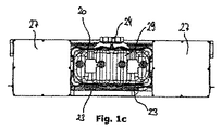
図1cには、パワーユニットの上面図が示されている。ジェネレータ41、42と電子機器ハウジング27の配置によって、パワーユニットの特にコンパクトな、特に幅狭の構造が得られることが、認識できる。さらに上面図では、シリンダヘッド20の形態が良好に認識できる。
FIG. 1c shows a top view of the power unit. It can be appreciated that the arrangement of the
シリンダヘッド20は、前側に排気スリーブ24を有している。排気スリーブ24は、二重管腔で形成されており、それぞれ各々のシリンダ21、22内へ連通している。シリンダヘッド20のそれぞれ逆となる前側には、吸気スリーブ23が配置されている。これらの吸気スリーブ23は、互いに離隔して配置されており、それぞれ直接第1のシリンダ21もしくは第2のシリンダ22内へ連通している。シリンダ21、22の各々に、別々の吸気スリーブ23が対応づけられている。
The
そのほか、図1cの上面図において、図面平面内で垂直の対称軸に関して、シリンダヘッド20が実質的に軸対称に形成されていることが、認識できる。これは、シリンダヘッド20はクランク軸ハウジング10上に2つの異なる方向づけで取り付けることができる、という利点を有している。特にシリンダヘッド20は、180°回動された方向づけでクランク軸ハウジング10上に取り付けることができるので、排気スリーブ24はパワーユニットの後ろ側へ向かう代わりに、前側へ向けて方向づけされている。
In addition, in the top view of FIG. 1c, it can be recognized that the
図2a−2cにおいて、パワーユニットが認識可能であり、それにおいてシリンダヘッド20は180°回動されてクランク軸ハウジング10上に取り付けられている。図1a−1dに示すパワーユニットの構成部品は、図2a−2cに示すパワーユニットの構成部品と実質的に同一である。差は、シリンダヘッド20が、図1a−1cのように組み立てた場合に、図2−2cのように組み立てた場合に対して、180°変位した方向づけでクランク軸ハウジング10上に取り付けられていることのみである。
In FIGS. 2 a-2 c, the power unit is recognizable, in which the
図1cにおいては、さらに弁カバー29が上から認識でき、その弁カバーはシリンダヘッド20上に取り付けられている。それに対して図1dは、パワーユニットの内部の構造を示しており、その場合にわかりやすくするために、クランク軸ハウジング10と弁カバー29が取り除かれている。
In FIG. 1 c, the
図1dにおいてよく認識できるように、パワーユニットは2つのクランク軸11、12を有しており、それらは同位相で互いに結合されている。結合は、平歯車34、35を介して行われ、それらは互いにかみ合う歯切りを有している。平歯車34、35はパワーユニットの後ろ側に配置されており、図3の露出した位置においてはっきりと認識できる。各平歯車34、35上にドライブ歯車36、37が取り付けられている。各ドライブ歯車36、37は、ベルト又はチェーンを介して1つのジェネレータ41、42の駆動歯車と結合されている。したがってクランク軸11、12とそれぞれ対応づけられたジェネレータ41、42との結合は、クランク軸11、12と同軸に結合されたドライブ歯車36、37、ベルトドライブ又はチェーンドライブ及び、ジェネレータ軸と同軸に相対回動不能に結合された、ジェネレータに設けられた駆動歯車を介して行われる。
As can be seen well in FIG. 1d, the power unit has two crankshafts 11, 12, which are coupled together in phase. The coupling is effected via spur gears 34, 35, which have gear teeth that mesh with each other. The spur gears 34 and 35 are arranged on the rear side of the power unit and can be clearly recognized in the exposed positions in FIG. Drive gears 36 and 37 are mounted on the spur gears 34 and 35, respectively. Each
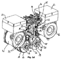
図1dには、パワーユニットの他の重要な視点が示されており、この視点は、パワーユニットの組み込み大きさの削減に寄与する。具体的には、図1dはカム軸30を示しており、そのカム軸はクランク軸11、12の間に位置している。特にカム軸30は、コネクティングロッド13の間でシリンダヘッド20の下方に延びている。具体的には、コネクティングロッド13がシリンダヘッド20及びクランク軸11、12と共に自由空間を画成しており、その自由空間がカム軸30によって効率的に利用される。カム軸30は特に2つのクランク軸11、12の間の中心線内に配置されている。カム軸30の駆動は、ベルトドライブ31を介して行われる。ベルトドライブ31は、第2のクランク軸12の歯車39をカム軸30と結合する。
FIG. 1d shows another important viewpoint of the power unit, which contributes to a reduction in the size of the power unit. Specifically, FIG. 1 d shows the camshaft 30, which is located between the crankshafts 11, 12. In particular, the cam shaft 30 extends below the
図示される実施例において、カム軸30は4つのカム32を有しており、それらのカムにそれぞれ制御ロッド33が対応づけられている。制御ロッド33は、カム軸30からクランク軸ハウジング10とシリンダヘッド20を通して弁カバー29の下方の弁室内へ延びている。弁室内にはロッカーアーム26が配置されており、そのロッカーアームが弁25と協働する。すなわち制御ロッド33を介してカム32の外側輪郭が検出されて、ロッカーアーム26の該当する傾き位置に変換される。ここに示される実施例において、全体で4つの弁が設けられていると、効果的である。したがって各制御ロッド33に、弁25が対応づけられている。
In the illustrated embodiment, the camshaft 30 has four cams 32, each of which is associated with a
図2aと2bはパワーユニットを示しており、そのパワーユニットは図1a、1bに示すパワーユニットに対して実質的に同様に形成されている。いずれにせよ、個々の構成部品は同一である。図2a、2bに示す表示は、シリンダヘッド20の配置が回動されていることによって、図1a、1bに示す組み立てから区別される。図2aに明らかなように、図1aに示す配置とは異なり、シリンダヘッド20は、排気スリーブ24がパワーユニットの前側へ向かって方向づけされるようにして、クランク軸ハウジング10上に取り付けられている。同様に弁カバー29も、図1aに示す組み立てに対して180°回動して取り付けられている。同じことが、図2bの表示についても実質的に当てはまり、それにおいては、図1bの表示に対して、シリンダヘッド20と弁カバー29が180°回動されてクランク軸ハウジング10上に取り付けられていることが、認識できる。
2a and 2b show a power unit, which is formed in substantially the same manner as the power unit shown in FIGS. 1a and 1b. In any case, the individual components are the same. The indications shown in FIGS. 2a and 2b are distinguished from the assembly shown in FIGS. 1a and 1b by the rotation of the
図2cは、図2a、2bに示すように組み立てた場合のパワーユニットを上面図で示している。図2cの上面図は図1cの上面図に比較して、同様に、シリンダヘッド20を2つの異なる方向づけでクランク軸ハウジング10上に取り付けることができることを、はっきりと示している。
FIG. 2c shows a top view of the power unit when assembled as shown in FIGS. 2a and 2b. The top view of FIG. 2c clearly shows that the
図3は、2つのクランク軸11、12を有する2シリンダ往復ピストンエンジンの内部構造を示しており、それらのクランク軸はそれぞれ平歯車34、35を有している。平歯車34、35の歯切りが互いにかみ合い、それによってピストン18、19の運動を同期させる。ピストンは、ここには示されないシリンダ21、22内にタンデム配置で案内されている。これは、ピストン18、19が同時にその上死点もしくは下死点に達することを意味している。
FIG. 3 shows the internal structure of a two-cylinder reciprocating piston engine having two crankshafts 11 and 12, which have
図3においては、同様に、全部で4つの弁25が設けられており、それらがロッカーアーム26を介して操作可能であることが、示されている。ロッカーアーム26は、4つの制御ロッド33と結合されており、その制御ロッドにはそれぞれカム軸30のカム32が対応づけられている。
In FIG. 3, it is likewise shown that a total of four valves 25 are provided and can be operated via the
クランク軸11、12に関しては、さらに、これらがドライブ歯車36、37とは逆の側にそれぞれはずみ車14、15を有していることが、認識できる。その場合に各はずみ車は、2シリンダ往復ピストンエンジン1の駆動時の振動を減少させるために、バランスマス16を有している。少なくとも、第1のクランク軸11と結合されている第1のはずみ車14は、周方向マーキング17を有している。この周方向マーキング17を用いてクランク軸センサが、シリンダ21、22内のピストン18、19の実際の位置を検出することができる。その場合に幅広のマーキングは、ピストン18、19の上死点又は下死点を表す。
As for the crankshafts 11 and 12, it can be further recognized that they have
添付図面から認識できるように、シリンダヘッド20を様々な方向づけでクランク軸ハウジング10上に取り付ける可能性によって、パワーユニットのための組み込み状況が個別に適合可能である。同時に、下方に位置するカム軸30が、パワーユニットの特にコンパクトな構造をもたらす。すなわち全体として、車両内で必要な組み込み空間を削減することができる。
As can be appreciated from the accompanying drawings, the possibility of mounting the
1 2シリンダ往復ピストンエンジン
10 クランク軸ハウジング
11 第1のクランク軸
12 第2のクランク軸
13 コネクティングロッド
14 第1のはずみ車
15 第2のはずみ車
16 バランスマス
17 周方向マーキング
18 第1のピストン
19 第2のピストン
20 シリンダヘッド
21 第1のシリンダ
22 第2のシリンダ
23 吸気スリーブ
24 排気スリーブ
25 弁
26 ロッカーアーム
27 電子機器ハウジング
28 カバー
29 弁カバー
30 カム軸
31 ベルトドライブ
32 カム
33 制御ロッド
34 第1の平歯車
35 第2の平歯車
36 第1のドライブ歯車
37 第2のドライブ歯車
39 歯車
41 第1のジェネレータ
42 第2のジェネレータ
1 2 cylinder
Claims (11)
往復ピストンエンジン(1)が下方に位置するカム軸(30)を有し、かつシリンダヘッド(20)が少なくとも2つの、特に互いに対して180°回動された位置において、クランク軸ハウジング(10)と結合可能であることを特徴とするパワーユニット。 A power unit, particularly a hybrid vehicle power unit, having a two-cylinder reciprocating piston engine (1) equipped with a crankshaft housing (10), and two crankshafts (11, 12) in the crankshaft housing. ), The crankshaft is connected to the pistons (18, 19) by connecting rods (13), the pistons are guided in two cylinders (21, 22) in a tandem arrangement, At least one crankshaft (11, 12) is drivingly coupled to the generator (41, 42), and the reciprocating piston engine (1) has a cylinder head (20), which is connected to the crankshaft housing (10). )
Crankshaft housing (10) in which the reciprocating piston engine (1) has a camshaft (30) located below and the cylinder head (20) is rotated at least two, in particular 180 ° relative to each other. A power unit that can be combined with the power unit.
Applications Claiming Priority (3)
| Application Number | Priority Date | Filing Date | Title |
|---|---|---|---|
| DE102016102048.6 | 2016-02-05 | ||
| DE102016102048.6A DE102016102048B4 (en) | 2016-02-05 | 2016-02-05 | generator |
| PCT/EP2017/052508 WO2017134294A1 (en) | 2016-02-05 | 2017-02-06 | Power unit |
Publications (2)
| Publication Number | Publication Date |
|---|---|
| JP2019505437A true JP2019505437A (en) | 2019-02-28 |
| JP6770078B2 JP6770078B2 (en) | 2020-10-14 |
Family
ID=57963237
Family Applications (1)
| Application Number | Title | Priority Date | Filing Date |
|---|---|---|---|
| JP2018540111A Active JP6770078B2 (en) | 2016-02-05 | 2017-02-06 | Power unit and vehicle |
Country Status (7)
| Country | Link |
|---|---|
| US (1) | US10844783B2 (en) |
| EP (1) | EP3411584B1 (en) |
| JP (1) | JP6770078B2 (en) |
| KR (1) | KR102181736B1 (en) |
| CN (1) | CN108474319B (en) |
| DE (1) | DE102016102048B4 (en) |
| WO (1) | WO2017134294A1 (en) |
Families Citing this family (2)
| Publication number | Priority date | Publication date | Assignee | Title |
|---|---|---|---|---|
| DE102020001432B3 (en) * | 2020-03-05 | 2021-03-25 | Obrist Technologies Gmbh | Generator set |
| DE102020118076A1 (en) | 2020-07-09 | 2022-01-13 | Bayerische Motoren Werke Aktiengesellschaft | Machine combination with internal combustion engine and generator |
Family Cites Families (22)
| Publication number | Priority date | Publication date | Assignee | Title |
|---|---|---|---|---|
| GB324410A (en) * | 1928-10-27 | 1930-01-27 | Harry Ralph Ricardo | Improvements in or relating to petrol-electric road vehicles |
| GB324409A (en) * | 1928-10-27 | 1930-01-27 | Harry Ralph Ricardo | Improvements in valve gear for internal combustion engines |
| GB463278A (en) * | 1935-11-13 | 1937-03-25 | Ariel Motors J S Ltd | Improvements relating to internal combustion engines |
| FR915993A (en) * | 1942-05-22 | 1946-11-22 | United Aircraft Corp | Cylinder heads improvements for internal combustion and air-cooled engines |
| GB584215A (en) * | 1944-12-15 | 1947-01-09 | Birmingham Small Arms Co Ltd | Improvements in or relating to internal combustion engines having twin cylinders with parallel axes |
| US2596410A (en) * | 1947-12-26 | 1952-05-13 | Le Grand L Jordan | Internal-combustion engine |
| JPS5217107A (en) | 1975-07-30 | 1977-02-08 | Nissan Motor Co Ltd | Engine |
| JPH0672546B2 (en) * | 1986-10-14 | 1994-09-14 | 本田技研工業株式会社 | General-purpose two-cylinder engine |
| DE19542758A1 (en) * | 1994-11-23 | 1996-05-30 | Luk Lamellen & Kupplungsbau | Pot=shaped flywheel for IC engine output shaft |
| US6280158B1 (en) | 1999-01-19 | 2001-08-28 | Honda Giken Kogyo Kabushiki Kaisha | Water pump for circulating cooling water in an internal combustion engine and camshaft mounting structure therefor |
| JP4201417B2 (en) | 1999-01-19 | 2008-12-24 | 本田技研工業株式会社 | Camshaft mounting structure |
| US20050051115A1 (en) * | 2003-07-09 | 2005-03-10 | Urs Wenger | Engine with rotatable cylinder head assembly |
| CA2551851C (en) * | 2004-01-17 | 2011-03-29 | Optimum Power Technology L.P. | Engine starting method |
| DE102004041958B4 (en) * | 2004-08-31 | 2017-01-19 | Deutz Ag | Reciprocating internal combustion engine with 2- or 4-valve cylinder head |
| DE102005048561A1 (en) * | 2005-10-11 | 2007-04-12 | Bayerische Motoren Werke Ag | Cylinder head for inline internal combustion engine, has exhaust gas turbocharger arranged at suction system and exhaust system, where fresh gas inlet geometry and exhaust gas outlet geometry are mirrored |
| CN200978717Y (en) * | 2006-03-14 | 2007-11-21 | 陆懋增 | Twin-tub v-shape diesel engine |
| CN1928328A (en) * | 2006-09-18 | 2007-03-14 | 陈维加 | Engine for portable generator |
| JP2008255971A (en) | 2007-04-09 | 2008-10-23 | Hino Motors Ltd | Rotary sensor |
| DE102010025002A1 (en) * | 2010-06-24 | 2011-12-29 | Fev Motorentechnik Gmbh | working machine |
| CH703972A1 (en) | 2010-10-29 | 2012-04-30 | Obrist Engineering Gmbh | Internal combustion engine. |
| AT511552B1 (en) * | 2011-05-30 | 2015-02-15 | Avl List Gmbh | GENERATOR FOR A MOTOR VEHICLE |
| JP6199102B2 (en) | 2013-07-19 | 2017-09-20 | 本田技研工業株式会社 | Engine generator |
-
2016
- 2016-02-05 DE DE102016102048.6A patent/DE102016102048B4/en active Active
-
2017
- 2017-02-06 KR KR1020187020842A patent/KR102181736B1/en active IP Right Grant
- 2017-02-06 US US16/073,220 patent/US10844783B2/en active Active
- 2017-02-06 EP EP17703152.3A patent/EP3411584B1/en active Active
- 2017-02-06 WO PCT/EP2017/052508 patent/WO2017134294A1/en active Application Filing
- 2017-02-06 JP JP2018540111A patent/JP6770078B2/en active Active
- 2017-02-06 CN CN201780007608.9A patent/CN108474319B/en active Active
Also Published As
| Publication number | Publication date |
|---|---|
| WO2017134294A1 (en) | 2017-08-10 |
| EP3411584B1 (en) | 2022-06-08 |
| US20190032554A1 (en) | 2019-01-31 |
| KR102181736B1 (en) | 2020-11-24 |
| DE102016102048A1 (en) | 2017-08-10 |
| US10844783B2 (en) | 2020-11-24 |
| DE102016102048B4 (en) | 2022-02-17 |
| KR20180105651A (en) | 2018-09-28 |
| EP3411584A1 (en) | 2018-12-12 |
| JP6770078B2 (en) | 2020-10-14 |
| CN108474319B (en) | 2021-07-30 |
| CN108474319A (en) | 2018-08-31 |
Similar Documents
| Publication | Publication Date | Title |
|---|---|---|
| JP7037804B2 (en) | Power generators and automobiles | |
| WO2008010490A1 (en) | Cycloid reciprocating engine and pump employing this crank mechanism | |
| US10837322B2 (en) | Opposed piston type engine | |
| JP2008309024A (en) | Variable compression ratio internal combustion engine | |
| JP2019505437A (en) | Power unit | |
| JP2018071446A (en) | Outboard engine and marine vessel | |
| JP2019011761A (en) | Internal combustion engine | |
| JP2020012452A (en) | Cover structure of internal combustion engine | |
| JP2015502488A (en) | Rotating drive system with cam follower with removable wheel support | |
| US4685428A (en) | Multi-cylinder internal combustion engine | |
| CN110195651B (en) | Engine | |
| US8757126B2 (en) | Non-reciprocating piston engine | |
| US9695741B2 (en) | Internal combustion engine | |
| JP2010532839A (en) | Internal combustion engine having a crankshaft and at least one cylinder head, and an automobile equipped with such an internal combustion engine | |
| JP2007297977A (en) | Outboard motor equipped with internal combustion engine provided with electric component box | |
| JP6506467B1 (en) | Opposed piston type engine | |
| CN104696434A (en) | Internal combustion engine balancer structure | |
| US20130092121A1 (en) | Orbital, non-reciprocating, internal combustion engine | |
| JP3635562B2 (en) | OHC V-type 2-cylinder engine | |
| EP3760833A1 (en) | Internal combustion engine | |
| JP6650796B2 (en) | Work machine engine | |
| JPH1191375A (en) | Power transmission device for engine | |
| JP6650795B2 (en) | Work machine engine | |
| JP6654936B2 (en) | Engine for work machine | |
| JP6455707B2 (en) | Internal combustion engine for vehicles |
Legal Events
| Date | Code | Title | Description |
|---|---|---|---|
| A621 | Written request for application examination |
Free format text: JAPANESE INTERMEDIATE CODE: A621 Effective date: 20181025 |
|
| A977 | Report on retrieval |
Free format text: JAPANESE INTERMEDIATE CODE: A971007 Effective date: 20190722 |
|
| A131 | Notification of reasons for refusal |
Free format text: JAPANESE INTERMEDIATE CODE: A131 Effective date: 20190730 |
|
| A521 | Request for written amendment filed |
Free format text: JAPANESE INTERMEDIATE CODE: A523 Effective date: 20191030 |
|
| A131 | Notification of reasons for refusal |
Free format text: JAPANESE INTERMEDIATE CODE: A131 Effective date: 20191210 |
|
| A521 | Request for written amendment filed |
Free format text: JAPANESE INTERMEDIATE CODE: A523 Effective date: 20200305 |
|
| A131 | Notification of reasons for refusal |
Free format text: JAPANESE INTERMEDIATE CODE: A131 Effective date: 20200407 |
|
| A521 | Request for written amendment filed |
Free format text: JAPANESE INTERMEDIATE CODE: A523 Effective date: 20200629 |
|
| TRDD | Decision of grant or rejection written | ||
| A01 | Written decision to grant a patent or to grant a registration (utility model) |
Free format text: JAPANESE INTERMEDIATE CODE: A01 Effective date: 20200825 |
|
| A61 | First payment of annual fees (during grant procedure) |
Free format text: JAPANESE INTERMEDIATE CODE: A61 Effective date: 20200924 |
|
| R150 | Certificate of patent or registration of utility model |
Ref document number: 6770078 Country of ref document: JP Free format text: JAPANESE INTERMEDIATE CODE: R150 |
|
| R250 | Receipt of annual fees |
Free format text: JAPANESE INTERMEDIATE CODE: R250 |