JP2019505191A - Method for stationary cleaning of high temperature food processing line and food sterilization line - Google Patents
Method for stationary cleaning of high temperature food processing line and food sterilization line Download PDFInfo
- Publication number
- JP2019505191A JP2019505191A JP2018532162A JP2018532162A JP2019505191A JP 2019505191 A JP2019505191 A JP 2019505191A JP 2018532162 A JP2018532162 A JP 2018532162A JP 2018532162 A JP2018532162 A JP 2018532162A JP 2019505191 A JP2019505191 A JP 2019505191A
- Authority
- JP
- Japan
- Prior art keywords
- food
- sequence
- line
- iii
- sterilization
- Prior art date
- Legal status (The legal status is an assumption and is not a legal conclusion. Google has not performed a legal analysis and makes no representation as to the accuracy of the status listed.)
- Granted
Links
Images


Classifications
-
- A—HUMAN NECESSITIES
- A23—FOODS OR FOODSTUFFS; TREATMENT THEREOF, NOT COVERED BY OTHER CLASSES
- A23C—DAIRY PRODUCTS, e.g. MILK, BUTTER OR CHEESE; MILK OR CHEESE SUBSTITUTES; MAKING THEREOF
- A23C7/00—Other dairy technology
- A23C7/02—Chemical cleaning of dairy apparatus; Use of sterilisation methods therefor
-
- A—HUMAN NECESSITIES
- A23—FOODS OR FOODSTUFFS; TREATMENT THEREOF, NOT COVERED BY OTHER CLASSES
- A23C—DAIRY PRODUCTS, e.g. MILK, BUTTER OR CHEESE; MILK OR CHEESE SUBSTITUTES; MAKING THEREOF
- A23C3/00—Preservation of milk or milk preparations
- A23C3/02—Preservation of milk or milk preparations by heating
- A23C3/03—Preservation of milk or milk preparations by heating the materials being loose unpacked
- A23C3/033—Preservation of milk or milk preparations by heating the materials being loose unpacked and progressively transported through the apparatus
-
- A—HUMAN NECESSITIES
- A23—FOODS OR FOODSTUFFS; TREATMENT THEREOF, NOT COVERED BY OTHER CLASSES
- A23L—FOODS, FOODSTUFFS, OR NON-ALCOHOLIC BEVERAGES, NOT COVERED BY SUBCLASSES A21D OR A23B-A23J; THEIR PREPARATION OR TREATMENT, e.g. COOKING, MODIFICATION OF NUTRITIVE QUALITIES, PHYSICAL TREATMENT; PRESERVATION OF FOODS OR FOODSTUFFS, IN GENERAL
- A23L2/00—Non-alcoholic beverages; Dry compositions or concentrates therefor; Their preparation
- A23L2/42—Preservation of non-alcoholic beverages
- A23L2/46—Preservation of non-alcoholic beverages by heating
-
- A—HUMAN NECESSITIES
- A61—MEDICAL OR VETERINARY SCIENCE; HYGIENE
- A61L—METHODS OR APPARATUS FOR STERILISING MATERIALS OR OBJECTS IN GENERAL; DISINFECTION, STERILISATION OR DEODORISATION OF AIR; CHEMICAL ASPECTS OF BANDAGES, DRESSINGS, ABSORBENT PADS OR SURGICAL ARTICLES; MATERIALS FOR BANDAGES, DRESSINGS, ABSORBENT PADS OR SURGICAL ARTICLES
- A61L2/00—Methods or apparatus for disinfecting or sterilising materials or objects other than foodstuffs or contact lenses; Accessories therefor
- A61L2/02—Methods or apparatus for disinfecting or sterilising materials or objects other than foodstuffs or contact lenses; Accessories therefor using physical phenomena
- A61L2/04—Heat
- A61L2/06—Hot gas
- A61L2/07—Steam
-
- A—HUMAN NECESSITIES
- A61—MEDICAL OR VETERINARY SCIENCE; HYGIENE
- A61L—METHODS OR APPARATUS FOR STERILISING MATERIALS OR OBJECTS IN GENERAL; DISINFECTION, STERILISATION OR DEODORISATION OF AIR; CHEMICAL ASPECTS OF BANDAGES, DRESSINGS, ABSORBENT PADS OR SURGICAL ARTICLES; MATERIALS FOR BANDAGES, DRESSINGS, ABSORBENT PADS OR SURGICAL ARTICLES
- A61L2/00—Methods or apparatus for disinfecting or sterilising materials or objects other than foodstuffs or contact lenses; Accessories therefor
- A61L2/16—Methods or apparatus for disinfecting or sterilising materials or objects other than foodstuffs or contact lenses; Accessories therefor using chemical substances
- A61L2/18—Liquid substances or solutions comprising solids or dissolved gases
-
- B—PERFORMING OPERATIONS; TRANSPORTING
- B08—CLEANING
- B08B—CLEANING IN GENERAL; PREVENTION OF FOULING IN GENERAL
- B08B9/00—Cleaning hollow articles by methods or apparatus specially adapted thereto
- B08B9/02—Cleaning pipes or tubes or systems of pipes or tubes
- B08B9/027—Cleaning the internal surfaces; Removal of blockages
- B08B9/032—Cleaning the internal surfaces; Removal of blockages by the mechanical action of a moving fluid, e.g. by flushing
- B08B9/0321—Cleaning the internal surfaces; Removal of blockages by the mechanical action of a moving fluid, e.g. by flushing using pressurised, pulsating or purging fluid
- B08B9/0325—Control mechanisms therefor
-
- A—HUMAN NECESSITIES
- A61—MEDICAL OR VETERINARY SCIENCE; HYGIENE
- A61L—METHODS OR APPARATUS FOR STERILISING MATERIALS OR OBJECTS IN GENERAL; DISINFECTION, STERILISATION OR DEODORISATION OF AIR; CHEMICAL ASPECTS OF BANDAGES, DRESSINGS, ABSORBENT PADS OR SURGICAL ARTICLES; MATERIALS FOR BANDAGES, DRESSINGS, ABSORBENT PADS OR SURGICAL ARTICLES
- A61L2202/00—Aspects relating to methods or apparatus for disinfecting or sterilising materials or objects
- A61L2202/10—Apparatus features
- A61L2202/17—Combination with washing or cleaning means
Abstract
食品加工ライン(30、40、50)上に並列に配置された第1の最終ヒータ(13)と第2の最終ヒータ(23)とを交互に動作させることによって、連続プロセスを動作させることが可能であり、さらに高温食品処理プロセスで現在使用されていない最終ヒータ(13、23)に対して定置洗浄プロセスを行うことによって、加工ライン(30、40、50)の全体的な休止時間を著しく低減させ、これによって、最も容易に汚染されるプロセス要素および/または加工装置による加工ライン(30、40、50)休止時間への影響をなくし、または著しく低減させる高温食品処理方法が開示される。 A continuous process can be operated by alternately operating a first final heater (13) and a second final heater (23) arranged in parallel on the food processing line (30, 40, 50). By performing a stationary cleaning process on the final heater (13, 23) that is possible and still not used in the high temperature food processing process, the overall downtime of the processing line (30, 40, 50) is significantly reduced. Disclosed is a high temperature food processing method that reduces, thereby eliminating or significantly reducing the impact on processing line (30, 40, 50) downtime by the most easily contaminated process elements and / or processing equipment.
Description
本発明は、食品を加工する分野、詳細には高温食品加工ラインを定置洗浄する方法に関する。さらに本発明は、本発明の方法の実行を可能にするように構成された高温食品加工ラインについて記載する。 The present invention relates to the field of processing foods, and in particular to a method for stationary cleaning of high temperature food processing lines. The present invention further describes a high temperature food processing line configured to allow the performance of the method of the present invention.
食品加工の分野では、熱処理による食品の滅菌は、頻発する課題である。熱処理による食品の滅菌の目的は、例えば、細菌、胞子、酵母、かび、またはバクテリオファージなどの微生物学的実体または微生物の数の低減である。特に、熱処理されている食品からの病原体の除去は、特に重要である。
最新の食品加工プラントは、加工される食品が運ばれる加工ライン内部の汚染を低減させるように設計されている。本設計における重要な要素は、例えば、ステンレス鋼などの低汚染の、および/または洗浄し保守するのが容易な材料を使用することだけでなく、定置洗浄(CIP)、すなわち、装置および加工ラインを分解することなく、加工ライン、プロセス要素、および加工装置の洗浄を可能にする加工ライン、プロセス要素、および加工装置を設計することである。
本発明は、定置洗浄のための方法の改良、および改良された方法で使用するのに最適化された加工ラインに関する。本開示全体にわたって、定置洗浄(cleaning−in−place)、CIP、および/または定置洗浄(cleaning in place)は、選好なしに交換可能に使用される。一般に、当業者は、特定のタイプの食品に応じた適切な定置洗浄方法を知っており、そのような方法は、一般に本開示の範囲外である。それにもかかわらず、食品滅菌ラインに関し以下で詳述するような本発明によるCIP手順を行う場合、CIP手順は、当技術分野で知られているような定置滅菌手順であることが必要である(および法律上必須である)。
In the field of food processing, sterilization of food by heat treatment is a frequent problem. The purpose of food sterilization by heat treatment is, for example, the reduction of the number of microbiological entities or microorganisms such as bacteria, spores, yeasts, molds or bacteriophages. In particular, the removal of pathogens from heat-treated foods is particularly important.
Modern food processing plants are designed to reduce contamination inside the processing line where processed food is carried. An important factor in this design is not only the use of low-contamination and / or easy-to-clean and maintainable materials such as stainless steel, but also in-place cleaning (CIP), ie equipment and processing lines Is to design processing lines, process elements, and processing equipment that allow cleaning of processing lines, process elements, and processing equipment.
The present invention relates to an improved method for in-situ cleaning, and a processing line optimized for use in the improved method. Throughout this disclosure, cleaning-in-place, CIP, and / or cleaning in-place are used interchangeably without preference. In general, one of ordinary skill in the art knows suitable in-place cleaning methods for a particular type of food, and such methods are generally outside the scope of this disclosure. Nevertheless, when performing a CIP procedure according to the present invention as detailed below with respect to a food sterilization line, the CIP procedure should be a stationary sterilization procedure as known in the art ( And legally required).
定置洗浄する場合に頻発する問題は、食品が運ばれるプロセス要素の所与のシーケンスを備える加工ラインにおいて同一の食品が異なる加工装置を異なるやり方で汚染するということである。例えば、低温熱交換器および高温熱交換器、例えば、プレヒータおよび最終ヒータを備えるプロセス要素のシーケンスでは、低温熱交換器は、通常、例えば、加工要素のシーケンスを通過するミルクによって高温熱交換器とは異なるやり方で汚染されるようになり、通常、例えば、ミルクは、低温熱交換器の表面よりも高温熱交換器の表面でより強く燃焼されるため、高温熱交換器が最も汚染されるようになる。
本開示の全体にわたって、プロセス要素(process element)と加工装置(processing equipment)とは区別され、すべての加工装置は、加工要素と見なされるが、すべてのプロセス要素が加工装置と見なされるわけではない。加工装置でもある加工要素の一例は、熱交換器である場合がある。熱交換器は、プロセスの別の要素に作用することによってプロセスにおいて作用し、したがって、加工要素かつ加工装置であるが、例えば、弁は、プロセスにおいて作用するが、プロセスの他の要素には作用しないため、弁は、プロセス要素ではあるが加工装置ではない。
A frequent problem with in-place cleaning is that the same food can contaminate different processing equipment in different ways in a processing line with a given sequence of process elements through which the food is carried. For example, in a sequence of process elements comprising a low temperature heat exchanger and a high temperature heat exchanger, e.g., a preheater and a final heater, the low temperature heat exchanger is typically connected with the high temperature heat exchanger by, for example, milk passing through the sequence of processing elements. Become contaminated in different ways, usually because, for example, milk is burned more strongly on the surface of the high temperature heat exchanger than on the surface of the low temperature heat exchanger, so that the high temperature heat exchanger is most contaminated. become.
Throughout this disclosure, a distinction is made between process elements and processing equipment and all processing devices are considered processing elements, but not all process elements are considered processing devices. . An example of a processing element that is also a processing device may be a heat exchanger. A heat exchanger acts in a process by acting on another element of the process, and thus is a machining element and machine, for example, a valve works in the process but not on other elements of the process. Therefore, the valve is a process element but not a processing device.
上記の例示的なプロセス要素のシーケンスを定置洗浄する場合、プロセス要素のシーケンスを定置洗浄するための所要時間は、通常、最も汚染された加工装置を洗浄するのに必要な時間によって決定される。また、プロセス要素のシーケンスは、加工装置の各要素をそれぞれ独立して汚染除去できるように設計することができるが、加工ラインは、少なくとも最長の洗浄時間を有する加工装置を洗浄するのに必要な時間停止したままである。
これは、最長の洗浄時間を有する加工装置が最終的に洗浄されている間、より短い洗浄時間を有する加工装置が、使える状態にあるもののアイドル状態にあるため、非常に不利である。特に、最も汚染された加工装置が洗浄を必要としているときに、一部の加工装置が最小限しか汚染されていない場合、加工装置の不必要な休止時間、および加工ラインがそのように構築されている場合、加工装置の不必要な洗浄も問題となる。
ところで、本発明者らは驚くことに、本明細書に開示された方法に従うことによって、この問題を克服し、または少なくとも著しく低減させることができることを発見した。
In the case of in-place cleaning of the exemplary process element sequence described above, the time required for in-place cleaning of the process element sequence is typically determined by the time required to clean the most contaminated processing equipment. The sequence of process elements can also be designed so that each element of the processing equipment can be decontaminated independently, but the processing line is required to clean the processing equipment with at least the longest cleaning time. Stay stopped for hours.
This is very disadvantageous because the processing device with the shorter cleaning time is in an idle state while it is ready for use while the processing device with the longest cleaning time is finally cleaned. In particular, when some of the most contaminated processing equipment needs cleaning and some of the processing equipment is minimally contaminated, unnecessary downtime of the processing equipment, and processing lines are so constructed. If this is the case, unnecessary cleaning of the processing equipment is also a problem.
By the way, the present inventors have surprisingly found that this problem can be overcome or at least significantly reduced by following the methods disclosed herein.
以下に提示される詳細な開示によると、本発明の目的は、本概要および詳細な説明において詳述されるような方法および生産ラインを提供することによって解決された。 According to the detailed disclosure presented below, the objects of the present invention have been solved by providing a method and production line as detailed in this summary and detailed description.
第1の態様および実施形態によると、食品処理プロセスにおいてポンプ輸送可能な食品(11)の物質流を、処理された製品(15)に変換しながら、定置洗浄手順中に食品加工ライン(30、40、50、60、70)を動作させる方法が本明細書で開示され、前記食品加工ライン(30、40、50、60、70)が、複数の動作可能に連続して配置された、流体接続されたプロセス要素(12、13、23、14)であって、前記複数のプロセス要素のうちの少なくとも第1および第2の実質的に同様のプロセス要素(13、23)が、それぞれ、前記食品加工ライン(30)上のプロセス要素の第1のシーケンス(I)および並列のシーケンス(III)上に並列に配置され、それにより、前記第2の実質的に同様のプロセス要素(23)を備える前記並列のシーケンス(III)を前記食品加工ライン(30)に対して、それぞれ弁(233、235)開閉するときに、前記第1の実質的に同様のプロセス要素(13)を備える前記第1のシーケンス(I)を前記食品加工ライン(30)に対して逆に弁(133、135)開閉するこができ、前記2つのシーケンス(I、III)のそれぞれが、前記それぞれのシーケンス(I、III)を前記食品加工ライン(30)から弁遮断している間に定置洗浄手順で使用するための洗浄剤をそれぞれのシーケンス(I、III)に出し入れ可能にするための、シーケンス(I;III)上のすべてのプロセス要素(13、23)のまわりに配置された入口弁(134、234)および出口弁(136、236)を備え、前記シーケンス(I、III)が、それぞれ前記入口弁(133、233)および出口弁(135、235)において前記食品加工ライン(30、40、50、60、70)から分流し、再結合する、プロセス要素(12、13、23、14)を備え、前記方法が、a)前記食品加工ライン(30)上で食品処理プロセスを実行する前に、プロセス要素の前記並列のシーケンス(III)を前記食品加工ライン(30)から弁(233、235)遮断し、前記食品(11)の物質流を通過させるためにプロセス要素の前記第1のシーケンス(I)を開放(133、135)したままにしておくステップと、b)前記食品処理プロセスを前記食品加工ライン(30)上で実行し、これによって前記食品処理プロセスにおいて前記食品(11)を処理された製品(15)に変換するステップと、c)前記食品処理プロセスを実行した時間の後に、前記食品処理プロセスの実行中に同時に、前記物質流を前記第1のシーケンス(I)の通過から前記並列のシーケンス(III)の通過へ切替え、これによって、前記第1のシーケンス(I)を前記食品加工ライン(30)から弁(133、135)遮断し、同時に、前記並列のシーケンス(III)を前記食品加工ライン(30)に開放(233、235)することによって、前記第1のシーケンス(I)を、前記食品加工ライン(30)において前記並列のシーケンス(III)に置き換えるステップと、d)前記第1のシーケンス(I)を前記食品加工ライン(30)から弁遮断している間に、前記第1のシーケンス(I)に対する定置洗浄手順を実行するステップと、を含む。 According to a first aspect and embodiment, a food processing line (30,) during a stationary cleaning procedure, while converting a substance stream of food (11) pumpable in a food processing process into a processed product (15). 40, 50, 60, 70) is disclosed herein, wherein the food processing line (30, 40, 50, 60, 70) is a plurality of operatively arranged fluids Connected process elements (12, 13, 23, 14), wherein at least first and second substantially similar process elements (13, 23) of the plurality of process elements, respectively, Arranged in parallel on a first sequence (I) and a parallel sequence (III) of process elements on the food processing line (30), whereby said second substantially similar process elements ( The first substantially similar process element (13) when opening and closing the valves (233, 235) to the food processing line (30) respectively in the parallel sequence (III) comprising 3) The first sequence (I) comprising the valve (133, 135) can be opened and closed in reverse with respect to the food processing line (30), and each of the two sequences (I, III) A sequence for allowing a detergent for use in a stationary cleaning procedure to be taken in and out of each sequence (I, III) while the sequence (I, III) is valve-closed from the food processing line (30) An inlet valve (134, 234) and an outlet valve (136, 236) disposed around all the process elements (13, 23) on (I; III), A process in which cans (I, III) divert from the food processing line (30, 40, 50, 60, 70) and recombine at the inlet valve (133, 233) and outlet valve (135, 235), respectively. Elements (12, 13, 23, 14), the method comprising: a) performing the parallel sequence (III) of process elements before the food processing process on the food processing line (30) Shut off valves (233, 235) from the processing line (30) and leave the first sequence (I) of process elements open (133, 135) to allow the food stream (11) to pass through. B) executing the food processing process on the food processing line (30), whereby the food (11) is processed in the food processing process. Converting the product stream from passing through the first sequence (I) at the same time during the execution of the food processing process after the time of performing the food processing process; Switching to the passage of the parallel sequence (III), thereby disconnecting the first sequence (I) from the food processing line (30) with the valves (133, 135) and at the same time the parallel sequence (III) Replacing the first sequence (I) with the parallel sequence (III) in the food processing line (30) by opening (233, 235) to the food processing line (30); d) While the first sequence (I) is shut off from the food processing line (30), a stationary cleaning hand for the first sequence (I) The and executing, a.
さらに、前記食品加工ライン(30、40、50、60、70)が停止されるまでおよび/または前記食品処理プロセスが終了するまで、ステップc)およびd)が繰り返される、第1の態様の第2の実施形態による方法が本明細書で開示される。
さらに、前記複数のプロセス要素(13、23)の前記第1および前記実質的に同様の第2のプロセス要素が、第1の最終ヒータ(13)および第2の最終ヒータ(23)である、第1の態様の第3の実施形態による方法が本明細書で開示される。
さらに、前記第1の最終ヒータ(13)および前記第2の最終ヒータ(23)が、両方とも直接水蒸気ヒータである、第1の態様の第4の実施形態による方法が本明細書で開示される。
さらに、前記最終ヒータ(13a、23a)が独立して保持セル(13b、23b)で増強されている、第1の態様の第5の実施形態による方法が本明細書で開示される。
Furthermore, steps c) and d) are repeated until the food processing line (30, 40, 50, 60, 70) is stopped and / or until the food processing process is completed. A method according to two embodiments is disclosed herein.
Further, the first and substantially similar second process elements of the plurality of process elements (13, 23) are a first final heater (13) and a second final heater (23). A method according to a third embodiment of the first aspect is disclosed herein.
Further disclosed herein is a method according to the fourth embodiment of the first aspect, wherein the first final heater (13) and the second final heater (23) are both direct steam heaters. The
Further disclosed herein is a method according to the fifth embodiment of the first aspect, wherein the final heater (13a, 23a) is independently augmented with holding cells (13b, 23b).
さらに、前記食品加工ライン(30、40、50、60、70)が、前記第1および前記並列のシーケンス(I、III)が前記食品加工ラインから分流する前に、前記食品加工ライン(30、40、50、60、70)上に配置された少なくとも1つのプレヒータ(12、32)をさらに備える、第1の態様の第6の実施形態による方法が本明細書で開示される。 Further, the food processing line (30, 40, 50, 60, 70) may be moved before the first and the parallel sequences (I, III) are diverted from the food processing line (30, Disclosed herein is a method according to a sixth embodiment of the first aspect, further comprising at least one preheater (12, 32) disposed on 40, 50, 60, 70).
さらに、前記食品加工ライン(30、40、50、60、70)が、前記第1および前記並列のシーケンス(I、III)が前記食品加工ラインと再結合した後に、前記食品加工ライン(30、40、50、60、70)上に配置された少なくとも1つのクーラ(14、44、54)をさらに備える、第1の態様の第7の実施形態による方法が本明細書で開示される。
さらに、前記クーラ(14)がフラッシュクーラ(14)、あるいは1つまたは複数の間接クーラ(441、541、542)で増強されたフラッシュクーラ(14)である、第1の態様の第8の実施形態による方法が本明細書で開示される。
さらに、充填ステーション(45、55)が前記食品加工ライン(40、50)上に配置された最終プロセス要素である、第1の態様の第9の実施形態による方法が本明細書で開示される。
さらに、供給タンク(41、51)が前記食品加工ライン(40、50)上に配置された第1のプロセス要素である、第1の態様の第10の実施形態による方法が本明細書で開示される。
さらに、前記弁(133、233)および/または前記弁(135、235)が対として単一の三方弁(58)に一体化されている、第1の態様の第11の実施形態による方法が本明細書で開示される。
さらに、前記食品加工ライン(30、40、50、60、70)が、液状食品(11)を低温殺菌または滅菌するための熱処理食品加工ラインである、第1の態様の第12の実施形態による方法が本明細書で開示される。
Further, the food processing line (30, 40, 50, 60, 70) may be used after the first and the parallel sequence (I, III) are recombined with the food processing line (30, Disclosed herein is a method according to a seventh embodiment of the first aspect, further comprising at least one cooler (14, 44, 54) disposed on 40, 50, 60, 70).
Further, the cooler (14) is a flash cooler (14) or a flash cooler (14) augmented with one or more indirect coolers (441, 541, 542). Eighth implementation of the first aspect A method according to form is disclosed herein.
Further disclosed herein is a method according to the ninth embodiment of the first aspect, wherein the filling station (45, 55) is a final process element disposed on the food processing line (40, 50). .
Further disclosed herein is a method according to the tenth embodiment of the first aspect, wherein the supply tank (41, 51) is the first process element disposed on the food processing line (40, 50). Is done.
Furthermore, the method according to the eleventh embodiment of the first aspect, wherein the valves (133, 233) and / or the valves (135, 235) are integrated into a single three-way valve (58) as a pair. Disclosed herein.
Further, according to the twelfth embodiment of the first aspect, the food processing line (30, 40, 50, 60, 70) is a heat-treated food processing line for pasteurizing or sterilizing the liquid food (11). A method is disclosed herein.
さらに、前記食品加工ライン(30、40、50、60、70)において、前記食品(11)が最初にプレヒータ(12)で予熱され、続いて、前記第1または前記並列のシーケンス(I、III)のいずれかにおいて高温処理にさらされる、第1の態様の第13の実施形態による方法が本明細書で開示される。
さらに、前記食品(11)がそれぞれの前記第1または並列のシーケンス(I、III)において、最初にプレヒータ(12、32)で低温殺菌温度にさらされ、続いて120℃を上回る滅菌高温処理にさらされる、第1の態様の第14の実施形態による方法が本明細書で開示される。
Furthermore, in the food processing line (30, 40, 50, 60, 70), the food (11) is first preheated with a preheater (12), and then the first or the parallel sequence (I, III). A method according to a thirteenth embodiment of the first aspect is disclosed herein which is exposed to a high temperature treatment in any of
Furthermore, in each said first or parallel sequence (I, III), the food (11) is first subjected to a pasteurization temperature with a preheater (12, 32), followed by a sterilization high temperature treatment above 120 ° C. An exposed method according to the fourteenth embodiment of the first aspect is disclosed herein.
第2の態様および実施形態によると、食品滅菌プロセスにおいてポンプ輸送可能な食品(11)の物質流を、滅菌された製品(15)に変換しながら、定置洗浄手順中に食品滅菌ライン(30、40、50、60、70)を動作させる方法が本明細書で開示され、前記食品滅菌ライン(30、40、50、60、70)が、ポンプ輸送可能な食品(11)を120〜160℃の温度で滅菌するための第1および第2の直接水蒸気ヒータ(13、23)を備える複数の動作可能に連続して配置された、流体接続されたプロセス要素(12、13、23、14)であって、前記第2の直接水蒸気ヒータ(23)を備える前記並列のシーケンス(III)を前記食品滅菌ライン(30、40、50、60、70)に対して、それぞれ弁(233、235)開閉するときに、前記第1の直接水蒸気ヒータ(13)を備える前記第1のシーケンス(I)を前記食品滅菌ライン(30、40、50、60、70)に対して逆に弁(133、135)開閉することができるように、前記食品滅菌ライン(30、40、50、60、70)上のプロセス要素の第1のシーケンス(I)および並列のシーケンス(III)上にそれぞれ並列に配置された、プロセス要素(12、13、23、14)であり、前記2つのシーケンス(I、III)のそれぞれが、前記それぞれのシーケンス(I、III)を前記食品滅菌ライン(30、40、50、60、70)から弁遮断している間に定置洗浄手順で使用するための洗浄剤をそれぞれのシーケンス(I、III)に出し入れ可能にするための、シーケンス(I;III)上のすべてのプロセス要素(13、23)のまわりに配置された入口弁(134、234)および出口弁(136、236)を備え、前記それぞれのシーケンス(I、III)が、前記それぞれの入口弁(133、233)および出口弁(135、235)において前記食品滅菌ライン(30)から分流し、再結合する、プロセス要素(12、13、23、14)を備え、前記方法が、a)食品滅菌ライン(30、40、50、60、70)上で食品滅菌プロセスを実行する前に、プロセス要素の前記並列のシーケンス(III)を前記食品滅菌ライン(30、40、50、60、70)から弁(233、235)遮断し、プロセス要素の前記第1のシーケンス(I)を前記食品(11)の物質流を通過させるために開放(133、135)したままにしておくステップと、b)前記第1および第2の直接水蒸気ヒータ(13、23)を120℃〜160℃の温度で動作させることによって、前記食品滅菌ライン(30、40、50、60、70)上で前記食品滅菌プロセスを実行し、これによって、前記食品滅菌プロセスにおいて前記食品(11)を滅菌された製品(15)に変換するステップと、c)前記食品滅菌プロセスを実行した時間の後に、前記食品滅菌プロセスの実行中に同時に、前記物質流を前記第1のシーケンス(I)の通過から前記並列のシーケンス(III)の通過へ切替え、これによって、前記第1のシーケンス(I)を前記食品滅菌ライン(30)から弁(133、135)遮断し、同時に、前記並列のシーケンス(III)を前記食品滅菌ライン(30)に開放(233、235)することによって、前記第1のシーケンス(I)を、前記食品滅菌ライン(30、40、50、60、70)において並列のシーケンス(III)に置き換えるステップと、d)前記第1のシーケンス(I)を前記食品滅菌ライン(30、40、50、60、70)から弁遮断している間に、前記第1のシーケンス(I)に対する定置洗浄手順を実行するステップと、を含む。 According to the second aspect and embodiment, the food sterilization line (30,) during the stationary cleaning procedure is converted into a sterilized product (15) while the substance stream of food (11) pumpable in the food sterilization process is converted. 40, 50, 60, 70) is disclosed herein, wherein the food sterilization line (30, 40, 50, 60, 70) is capable of pumping food (11) at 120-160 ° C. A plurality of operatively arranged fluidly connected process elements (12, 13, 23, 14) comprising first and second direct steam heaters (13, 23) for sterilization at a temperature of Wherein the parallel sequence (III) comprising the second direct steam heater (23) is connected to the food sterilization line (30, 40, 50, 60, 70) respectively with valves (233, 2 5) When opening and closing, the first sequence (I) comprising the first direct steam heater (13) is reversed with respect to the food sterilization line (30, 40, 50, 60, 70) ( 133, 135) can be opened and closed in parallel on the first sequence (I) and parallel sequence (III) of the process elements on the food sterilization line (30, 40, 50, 60, 70), respectively. Process elements (12, 13, 23, 14), each of the two sequences (I, III) being replaced with the respective sequence (I, III) of the food sterilization line (30, 40). , 50, 60, 70) in order to allow a cleaning agent for use in a stationary cleaning procedure to be taken in and out of each sequence (I, III) while the valve is shut off from Comprising an inlet valve (134, 234) and an outlet valve (136, 236) arranged around all process elements (13, 23) on (I; III), said respective sequences (I, III) being A process element (12, 13, 23, 14) that diverts and recombines from the food sterilization line (30) at the respective inlet valve (133, 233) and outlet valve (135, 235); Before the method performs the food sterilization process on a) the food sterilization line (30, 40, 50, 60, 70), the parallel sequence (III) of process elements is converted to the food sterilization line (30, 40, 50, 60, 70) are shut off from the valve (233, 235) and the first sequence (I) of process elements is opened (1) to pass the substance stream of the food (11). 33, 135) and b) operating the first and second direct steam heaters (13, 23) at a temperature of 120 ° C. to 160 ° C., whereby the food sterilization line (30, 40, 50, 60, 70) carrying out the food sterilization process thereby converting the food (11) into a sterilized product (15) in the food sterilization process; c) the food sterilization At the same time during the execution of the food sterilization process after the time the process has been carried out, the material flow is switched from passing through the first sequence (I) to passing through the parallel sequence (III), whereby 1 sequence (I) is shut off from the food sterilization line (30) with the valves (133, 135) and at the same time the parallel sequence (III) is Replacing the first sequence (I) with a parallel sequence (III) in the food sterilization line (30, 40, 50, 60, 70) by opening (233, 235) to the line (30) And d) a stationary cleaning procedure for the first sequence (I) while the first sequence (I) is valve-blocked from the food sterilization line (30, 40, 50, 60, 70). Executing.
さらに、第2の態様の第2の実施形態によると、定置洗浄手順中に食品滅菌ライン(30、40、50、60、70)を動作させる方法であって、前記ポンプ輸送可能な食品(11)を滅菌する間に、前記第1および第2の直接水蒸気ヒータ(13、23)を120℃〜160℃の温度で0.5〜10秒の時間動作させる、方法が本明細書で開示される。 Furthermore, according to a second embodiment of the second aspect, there is provided a method for operating a food sterilization line (30, 40, 50, 60, 70) during a stationary cleaning procedure, wherein said pumpable food (11 ), The first and second direct steam heaters (13, 23) are operated at a temperature of 120 ° C. to 160 ° C. for a time of 0.5 to 10 seconds. The
さらに、第2の態様の第3の実施形態によると、定置洗浄手順中に食品滅菌ライン(30、40、50、60、70)を動作させる方法であって、前記第1および第2の直接水蒸気ヒータ(13、23)が保持セル(13b、23b)を有する直接水蒸気ヒータ(13a、23a)の組合せを備える、方法が本明細書で開示される。 Furthermore, according to a third embodiment of the second aspect, a method of operating a food sterilization line (30, 40, 50, 60, 70) during a stationary cleaning procedure, wherein the first and second direct Disclosed herein is a method wherein the steam heater (13, 23) comprises a combination of direct steam heaters (13a, 23a) having holding cells (13b, 23b).
さらに、第2の態様の第4の実施形態によると、定置洗浄手順中に食品滅菌ライン(30、40、50、60、70)を動作させる方法であって、前記直接水蒸気ヒータ(13a、23a)での加熱時間が2秒未満であり、前記保持セル(13b、23b)での保持時間が1秒〜約10秒である、方法が本明細書で開示される。
さらに、第1または第2の態様によると、前記ポンプ輸送可能な食品(11)がミルク、ミルク派生品、ジュース、野菜液状食品、豆乳、スープ、および/またはデザートである、方法が本明細書で開示される。
Furthermore, according to a fourth embodiment of the second aspect, there is a method for operating a food sterilization line (30, 40, 50, 60, 70) during a stationary cleaning procedure, wherein the direct steam heater (13a, 23a) is operated. ) Is less than 2 seconds and the retention time in the holding cells (13b, 23b) is 1 second to about 10 seconds.
Further according to the first or second aspect, there is provided a method herein wherein said pumpable food (11) is milk, milk derivatives, juice, vegetable liquid food, soy milk, soup and / or dessert. Is disclosed.
第3の態様および実施形態によると、ポンプ輸送可能な食品(11)を120〜160℃の温度で滅菌するための第1および第2の直接水蒸気ヒータ(13、23)を備える複数の動作可能に連続して配置された、流体接続されたプロセス要素(42、52、13、23、44、54)であって、前記第2の直接水蒸気ヒータ(23)を備える前記並列のシーケンス(III)を前記食品加工ライン(30)に対して、それぞれ弁(233、235)開閉するときに、前記第1の直接水蒸気ヒータ(13)を備える前記第1のシーケンス(I)を前記食品滅菌ライン(40、50)に対して逆に弁(133、135)開閉することができるように、前記食品滅菌ライン(40、50)上のプロセス要素の第1の滅菌シーケンス(I)および並列の滅菌シーケンス(III)上にそれぞれ動作可能に並列に配置された、プロセス要素(42、52、13、23、44、54)であり、前記2つのシーケンス(I、III)のそれぞれが、前記それぞれのシーケンス(I、III)を食品滅菌ライン(40、50)から弁遮断している間に定置洗浄手順で使用するための洗浄剤をそれぞれのシーケンス(I、III)に出し入れ可能にするための、シーケンス(I;III)上のすべてのプロセス要素(13、23)のまわりに配置された入口弁(134、234)および出口弁(136、236)を備え、前記それぞれのシーケンス(I、III)が、前記それぞれの入口弁(133、233)および出口弁(135、235)において前記食品滅菌ライン(40、50)から分流し、再結合する、プロセス要素(42、52、13、23、44、54)を備え、前記食品滅菌ライン(40、50)が、前記シーケンスが前記食品滅菌ライン(40、50)から分流する前に、前記シーケンス(I、III)の上流の前記食品滅菌ライン(40、50)上に動作可能に配置されたプレヒータ(42、52)と、前記シーケンスが前記食品滅菌ライン(40、50)と再結合した後に、前記シーケンス(I、III)の下流の前記食品滅菌ライン(40、50)上に動作可能に配置されたフラッシュクーラ(44、54)と、をさらに備える、食品滅菌ライン(40、50)において、一方のシーケンス(I、III)が食品滅菌プロセスのための動作可能な滅菌シーケンスとして利用可能なときに、もう一方のシーケンス(I、III)が食品滅菌プロセスのための動作可能な滅菌シーケンスとして利用可能ではない、ことを特徴とする、食品滅菌ライン(40、50)が本明細書で開示される。
さらに、第3の態様の第2の実施形態によると、前記プレヒータ(42、52)の上流の前記食品滅菌ライン(40、50)上に動作可能に配置された供給タンク(41、51)をさらに備える食品滅菌ライン(40、50)が本明細書で開示される。
さらに、第3の態様の第3の実施形態によると、前記食品滅菌ライン(40、50)の下流端に配置された充填ステーション(45、55)をさらに備える食品滅菌ライン(40、50)が本明細書で開示される。
According to a third aspect and embodiment, a plurality of operable with first and second direct steam heaters (13, 23) for sterilizing pumpable food (11) at a temperature of 120-160 ° C. The parallel sequence (III) comprising fluid-connected process elements (42, 52, 13, 23, 44, 54) arranged in series, comprising the second direct steam heater (23) When the valve (233, 235) is opened and closed with respect to the food processing line (30), the first sequence (I) including the first direct steam heater (13) is changed to the food sterilization line ( The first sterilization sequence (I) and the parallel of the process elements on the food sterilization line (40, 50) so that the valves (133, 135) can be opened and closed with respect to 40, 50). Process elements (42, 52, 13, 23, 44, 54), each operatively arranged in parallel on a sterilization sequence (III) of each of the two sequences (I, III), In order to allow cleaning agents to be used in and out of each sequence (I, III) for use in a stationary cleaning procedure while each sequence (I, III) is valve shut off from the food sterilization line (40, 50) Each having an inlet valve (134, 234) and an outlet valve (136, 236) arranged around all process elements (13, 23) on the sequence (I; III), said respective sequence (I, III) is diverted from the food sterilization line (40, 50) at the respective inlet valve (133, 233) and outlet valve (135, 235). Reprocessed, comprising process elements (42, 52, 13, 23, 44, 54) before the food sterilization line (40, 50) diverts the sequence from the food sterilization line (40, 50) A preheater (42, 52) operably disposed on the food sterilization line (40, 50) upstream of the sequence (I, III); and the sequence is re-connected to the food sterilization line (40, 50). A flash cooler (44, 54) operatively disposed on the food sterilization line (40, 50) downstream of the sequence (I, III) after being coupled, the food sterilization line (40, 50), when one sequence (I, III) is available as an operable sterilization sequence for the food sterilization process, the other sequence (I Disclosed herein is a food sterilization line (40, 50), characterized in that III, III) is not available as an operable sterilization sequence for the food sterilization process.
Furthermore, according to a second embodiment of the third aspect, a supply tank (41, 51) operatively arranged on the food sterilization line (40, 50) upstream of the preheater (42, 52) is provided. Additional food sterilization lines (40, 50) are disclosed herein.
Furthermore, according to a third embodiment of the third aspect, the food sterilization line (40, 50) further comprising a filling station (45, 55) disposed at the downstream end of the food sterilization line (40, 50). Disclosed herein.
さらに、第3の態様の第4の実施形態によると、前記フラッシュクーラ(44、54)の後の、および存在する場合は前記充填ステーション(45、55)の前の、前記食品滅菌ライン(40、50)上に配置された少なくとも1つの間接クーラ(441、541、542)をさらに備える食品滅菌ライン(40、50)が本明細書で開示される。
さらに、第3の態様の第5の実施形態によると、第1および第2の態様ならびにこれらの実施形態のいずれかによる方法を実行するためのコントローラをさらに備える食品滅菌ライン(40、50)が本明細書で開示される。
Furthermore, according to a fourth embodiment of the third aspect, the food sterilization line (40) after the flash cooler (44, 54) and, if present, before the filling station (45, 55). 50) Disclosed herein is a food sterilization line (40, 50) further comprising at least one indirect cooler (441, 541, 542) disposed thereon.
Furthermore, according to a fifth embodiment of the third aspect, there is a food sterilization line (40, 50) further comprising a controller for performing the first and second aspects and the method according to any of these embodiments. Disclosed herein.
例えば、乳製品、ジュース、またはスープなどの食品の熱処理では、特に食品の滅菌では、食品がプロセス要素を汚し、これによって加工要素上に砕片の層を蓄積することが繰返し発生する問題である。食品滅菌プロセスは、例えば、温度に特に敏感であり、例えば、100℃を超えるより高い温度で動作する加工装置は、より低い温度で動作する加工装置よりも、一般に、食品熱処理ラインを備える加工プラントを流れる食品の所与の流速でより多くかつより速く汚れる。 For example, in the heat treatment of foods such as dairy products, juices, or soups, especially in sterilization of foods, it is a recurring problem that foods contaminate the process elements and thereby build up a layer of debris on the processing elements. Food sterilization processes are particularly sensitive to temperature, for example, processing equipment that operates at higher temperatures, eg, greater than 100 ° C., is generally a processing plant that includes a food heat treatment line than processing equipment that operates at lower temperatures. More and faster soiling at a given flow rate of food flowing through.
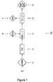
図1は、ポンプ輸送可能な食品を熱処理するための、例えば、低温殺菌ための、超高温処理(UHT処理)ための、および/または滅菌のための典型的な従来技術の加工ライン(10)を詳述する。本プロセスは、例えば、国際公開第2004/077968号に例示されている。表示されたプロセスでは、食品(11)は、プレヒータ(12)で予熱され、第1の最終ヒータ(13)で滅菌温度に加熱され、(フラッシュ)クーラ(14)で冷却されて、熱処理された製品を生成する。(ジュース処理のために国際公開第2004/077968号に例示されている)図のプロセスは、水蒸気(16)を使用したインフュージョンまたはインジェクション加熱(13)のための第1の最終ヒータ、および蒸気(17)を同時回収するフラッシュ冷却(14)の形態の冷却を利用して、熱処理された製品(15)を生成する。
したがって、本図に詳述された加工ライン(10)は、連続して配置された、例えば、パイプによって流体接続された、流体接続されたプロセス要素(12、13、14)のシーケンス(I)を備え、特定の食品に対して意図されたこの特定の食品の熱処理および/または滅菌プロセスの要求に従って、食品(11)をポンプ輸送することによって加工ライン(10)を通過させることができる。
FIG. 1 shows a typical prior art processing line (10) for heat treating pumpable foods, eg, for pasteurization, for ultra high temperature processing (UHT processing), and / or for sterilization. Is described in detail. This process is exemplified in, for example, WO 2004/077968. In the indicated process, the food (11) was preheated with a preheater (12), heated to a sterilization temperature with a first final heater (13), cooled with a (flash) cooler (14) and heat treated. Generate a product. The illustrated process (illustrated in WO 2004/0797968 for juice processing) includes a first final heater for infusion or injection heating (13) using steam (16), and steam Cooling in the form of flash cooling (14) with simultaneous recovery of (17) is used to produce a heat treated product (15).
Thus, the processing line (10) detailed in this figure is a sequence (I) of fluidly connected process elements (12, 13, 14) arranged in series, eg fluidly connected by pipes. Can be passed through the processing line (10) by pumping the food (11) according to the requirements of the heat treatment and / or sterilization process of this particular food intended for the particular food.
食品を、流体接続されたプロセス要素(12、13、14)のシーケンス(I)を通して輸送するために、1つまたは複数の食品ポンプが所望の物質輸送のための必要な駆動力を供給する。当業者は、本発明の文脈において、所与のタイプの食品および流速に対して、前述の流体接続されたプロセス要素のシーケンス(I)に沿って適切な位置で1つまたは複数の食品ポンプを適用し、前記流体接続されたプロセス要素のシーケンス(I)を通して食品(11)を適切に輸送し、所望の熱処理および/または滅菌プロセスを実行することができるように、食品ポンプを適切に寸法決めし適用するための要件に精通している。
それゆえ、食品ポンプが前記流体接続されたプロセス要素のシーケンス(I)に含まれてもよいと理解されるであろうが、そのような食品ポンプの詳細は、特定の食品、ならびにプロセス要素のシーケンス(I)において実行される熱処理および/または滅菌プロセスの方法に特有のものとして、本発明の範囲外と考えられる。
In order to transport food through the sequence (I) of fluidly connected process elements (12, 13, 14), one or more food pumps provide the necessary driving force for the desired material transport. One skilled in the art, in the context of the present invention, has one or more food pumps at appropriate locations along the aforementioned fluid-connected process element sequence (I) for a given type of food and flow rate. Apply and dimension the food pump appropriately so that it can properly transport the food (11) through the sequence (I) of the fluidly connected process elements and perform the desired heat treatment and / or sterilization process. Be familiar with the requirements to apply.
Therefore, it will be understood that a food pump may be included in the sequence (I) of the fluidly connected process elements, but details of such food pumps are specific to the food as well as the process elements. Specific to the method of heat treatment and / or sterilization process performed in sequence (I) is considered outside the scope of the present invention.
図2は、食品を熱処理するための、例えば、低温殺菌のための、超高温処理(UHT処理)のための、および/または滅菌のための別の従来技術の加工ライン(20)を詳述する。本プロセスは、例えば、国際公開第2004/077968号に例示されている。表示されたプロセスでは、食品(11)は、予熱(12)され、セパレータ(18)において2つの異なる製品流に分離され、続いて各製品流が、2つの別個の最終ヒータである、第1の最終ヒータ(13)および第2の最終ヒータ(23)において滅菌温度に加熱され、2つの製品流が、個々に冷却されるか(図示せず)、またはフラッシュクーラ(14)において混合され冷却されて、熱処理された製品を生成する。最終ヒータの後に保持セル(図示せず)が配置され、インジェクタ温度で1秒以下の保持セル熱処理が行われる。
(ジュース処理のために国際公開第2004/077968号に例示されている)図のプロセスは、水蒸気(16)を使用したインフュージョンまたはインジェクション加熱(13)のための並列に配置された第1および第2の最終ヒータ、ならびに蒸気(17)を同時回収するフラッシュ冷却(14)の形態の冷却を利用して、熱処理された製品(15)を生成する。しかしながら、セパレータ(18)のために、分離されて、閉鎖ラインへ導かれる材料が、全プロセス物質流の障害となるため、最終ヒータのいずれかを、もう一方もシャットダウンさせることなく、したがって全生産ラインをシャットダウンさせることなくシャットダウンさせることは不可能である。
FIG. 2 details another prior art processing line (20) for heat treating foods, eg, for pasteurization, for ultra high temperature processing (UHT processing), and / or for sterilization. To do. This process is exemplified in, for example, WO 2004/077968. In the indicated process, the food product (11) is preheated (12) and separated in a separator (18) into two different product streams, followed by each product stream being two separate final heaters. The final heater (13) and the second final heater (23) are heated to the sterilization temperature and the two product streams are cooled individually (not shown) or mixed and cooled in the flash cooler (14). To produce a heat treated product. A holding cell (not shown) is disposed after the final heater, and a holding cell heat treatment is performed for 1 second or less at the injector temperature.
The illustrated process (illustrated in WO 2004/077968 for juice processing) is a first and second arranged in parallel for infusion or injection heating (13) using steam (16). The second final heater and cooling in the form of flash cooling (14) with simultaneous recovery of steam (17) are utilized to produce a heat treated product (15). However, because of the separator (18), the material that is separated and led to the closed line becomes an obstacle to the overall process material flow, so that one of the final heaters does not shut down the other, and therefore the entire production. It is impossible to shut down a line without shutting it down.
したがって、図2に詳述された加工ライン(20)は、連続して配置された、例えば、パイプによって流体接続された、流体接続されたプロセス要素(12、13、23、14)のシーケンス(II)を備え、特定の食品に対して意図されたこの特定の食品の熱処理および/または滅菌プロセスの要求に従って、食品(11)を加工ライン(20)を介して通過させることができ、第1の最終ヒータ(13)および第2の最終ヒータ(23)が、この加工ライン(20)上に並列に配置されている。
従来技術の例示された両方の加工ライン(10、20)では、図で最終ヒータ1(13)および最終ヒータ2(23)とラベル付けされたプロセス要素、すなわち、第1および第2の最終ヒータは、これらのプロセス要素が最も高い温度で動作するため、加工ラインで処理されている食品による汚れに最も脆弱である。それゆえ、加工ライン(10、20)の休止時間は、(主に)最終ヒータ(13、23)の動作条件を維持する必要性によって決定され、これによって、さらなるプロセス要素および/または加工装置が十分に利用されなくなる。
Thus, the processing line (20) detailed in FIG. 2 comprises a sequence of fluidly connected process elements (12, 13, 23, 14) arranged in series, eg fluidly connected by pipes ( II), the food (11) can be passed through the processing line (20) according to the requirements of the heat treatment and / or sterilization process of this particular food intended for the particular food, The final heater (13) and the second final heater (23) are arranged in parallel on the processing line (20).
In both prior art illustrated processing lines (10, 20), the process elements labeled final heater 1 (13) and final heater 2 (23) in the figure, ie first and second final heaters. Are most vulnerable to contamination by food processed in the processing line because these process elements operate at the highest temperatures. Therefore, the downtime of the processing line (10, 20) is determined (mainly) by the need to maintain the operating conditions of the final heater (13, 23), which allows further process elements and / or processing equipment to be used. It will not be fully used.
異なる食品が同時に熱処理される国際公開第2004/077968号で論じられたプロセスなどでさえ、最終ヒータの一方のみが、もう一方のヒータよりも脆弱な場合、例示された最終ヒータ(13、23)のうちの最も脆弱なものが汚れのために洗浄を必要としているときはいつも加工ライン(20)全体が動作を中止しなければならないという大きな問題が残されている。 Even if only one of the final heaters is more fragile than the other heater, such as the process discussed in WO 2004/077968 where different foods are heat treated simultaneously, the illustrated final heater (13, 23) The major problem remains that the entire processing line (20) must be stopped whenever the most vulnerable of these require cleaning due to contamination.
本発明者らは、驚くことに今や、プロセス要素のシーケンス(II)上に並列に配置された第1の最終ヒータ(13)と第2の最終ヒータ(23)との間で高温食品処理プロセスを交互に動作させることによって、連続的なプロセスを動作させることができ、さらに、高温食品処理プロセスで現在使用されていない最終ヒータに対する定置洗浄プロセスを行うことによって加工ラインの全体的な休止時間を著しく低減させ、これによって、最も容易に汚染されるプロセス要素および/または加工装置による加工ラインの休止時間への影響をなくし、または著しく低減させることを実現した。
図3は、本開示の本発明の方法を実行するように配置された加工ライン(30)を詳述する。
The inventors now surprisingly have a high temperature food processing process between a first final heater (13) and a second final heater (23) arranged in parallel on the sequence (II) of process elements. Can be operated in a continuous manner, and can also reduce the overall downtime of the processing line by performing a stationary cleaning process on the final heater that is not currently used in high temperature food processing processes. A significant reduction has been achieved, thereby eliminating or significantly reducing the impact on downtime of the processing line by the most easily contaminated process elements and / or processing equipment.
FIG. 3 details the processing line (30) arranged to perform the inventive method of the present disclosure.
ポンプ輸送可能な食品(11)、好ましくはポンプ輸送可能な液状食品、より好ましくはミルク、ミルク派生品、ジュース、野菜液状食品、豆乳、スープ、および/またはデザート、ならびに/あるいは最も好ましくはミルク派生品が加工ライン(30)に提供され、加工ライン(30)が、少なくとも2つの連続して流体接続されたプロセス要素(12、13、14)を備える。食品は、ポンプ輸送によって、少なくとも2つの連続して流体接続されたプロセス要素(12、13、14)を横切ることができ、前述の加工ライン(30)を通過した後に処理された製品(15)を生成する。これによって、食品(11)の物質流が加工ライン(30)を通して確立される。例示された加工ライン(30)では、処理プロセスは、食品滅菌プロセスであり、食品(11)がプレヒータ(12)で第1の温度に予熱され、続いて第1の最終ヒータ(13)で最終加工温度に加熱され、今や熱処理された製品となった食品がクーラ(14)で冷却されて、所望の処理された製品(15)を生成する。
好ましい実施形態では、第1の温度は、食品(11)が食品加工ライン(30)で処理される低温殺菌温度、例えば、脱脂乳に対しては75℃であり、および/または最終加工温度は、滅菌温度、例えば、脱脂乳に対しては146℃である。一般に、当業者は、所与の食品に対する低温殺菌および滅菌温度を決定する仕方を知っており、本発明は、本発明の食品加工ライン(30)上で実行される所与の食品プロセスにおいて食品(11)が被る実際の温度によって限定されない。
Pumpable food (11), preferably pumpable liquid food, more preferably milk, milk derivatives, juice, vegetable liquid food, soy milk, soup and / or dessert, and / or most preferably milk derived An article is provided to the processing line (30), the processing line (30) comprising at least two sequentially fluidly connected process elements (12, 13, 14). The food product can be traversed by at least two consecutive fluidly connected process elements (12, 13, 14) by pumping and processed after passing through the aforementioned processing line (30) (15) Is generated. Thereby, the material flow of the food (11) is established through the processing line (30). In the illustrated processing line (30), the treatment process is a food sterilization process, where the food (11) is preheated to a first temperature with a preheater (12) and subsequently finalized with a first final heater (13). The food product, heated to the processing temperature and now a heat treated product, is cooled with a cooler (14) to produce the desired treated product (15).
In a preferred embodiment, the first temperature is a pasteurization temperature at which the food product (11) is processed in the food processing line (30), eg 75 ° C. for skim milk and / or the final processing temperature is The sterilization temperature is, for example, 146 ° C. for skim milk. In general, those skilled in the art know how to determine pasteurization and sterilization temperatures for a given food, and the present invention relates to food in a given food process performed on the food processing line (30) of the present invention. It is not limited by the actual temperature that (11) is subjected to.
例示された加工ライン(30)では、例示された実施形態の第1および第2の最終ヒータ(13、23)は両方とも、水蒸気(16)を利用した直接水蒸気加熱によって、すなわちインジェクション(直接水蒸気インジェクション、DSIインジェクション)またはインフュージョン(直接水蒸気インフュージョン)によって動作し、いずれの選択肢も好まれる。さらに、例示された加工ライン(30)では、クーラ(14)は、冷却プロセスからの余剰水が蒸気(17)として回収されるフラッシュクーラ(14)である。一般に、直接水蒸気加熱は、燃焼を低減させ、最終製品(15)の味が、調理された味を弱めた初期食品(11)の味に近くなるため、食品加工ラインにおいて滅菌温度を確立するための熱交換器よりも好ましい。
一般に、本発明の方法による食品滅菌プロセスを実行する場合、直接水蒸気ヒータの動作温度は、120℃〜160℃、好ましくは125℃〜150℃、より好ましくは130℃〜147℃、最も好ましくは135℃〜144℃であることが意図されている。
さらに、滅菌温度の合計の加熱時間は、0.5〜10秒、好ましくは1〜9秒、より好ましくは2〜8秒、一層好ましくは3〜7秒、最も好ましくは4〜6秒であることが意図されている。
一部の実施形態では、最終ヒータ(13、23)は、直接水蒸気ヒータ(13a、23a)と保持セル(13b、23b)との組合せとすることができる(図5参照)。この状況では、直接水蒸気ヒータでの加熱時間が2秒未満であり、保持セルでの保持時間が1秒〜約10秒であるのが好ましい。
In the illustrated processing line (30), the first and second final heaters (13, 23) of the illustrated embodiment are both by direct steam heating utilizing steam (16), ie, injection (direct steam It works by injection, DSI injection) or infusion (direct steam infusion), and either option is preferred. Further, in the illustrated processing line (30), the cooler (14) is a flash cooler (14) in which excess water from the cooling process is recovered as steam (17). In general, direct steam heating reduces combustion and establishes a sterilization temperature in the food processing line because the taste of the final product (15) is closer to the taste of the cooked initial food (11). It is preferable to the heat exchanger.
In general, when performing a food sterilization process according to the method of the present invention, the operating temperature of the direct steam heater is 120 ° C to 160 ° C, preferably 125 ° C to 150 ° C, more preferably 130 ° C to 147 ° C, most preferably 135. C. to 144.degree. C. is intended.
Furthermore, the total heating time of the sterilization temperature is 0.5 to 10 seconds, preferably 1 to 9 seconds, more preferably 2 to 8 seconds, more preferably 3 to 7 seconds, and most preferably 4 to 6 seconds. Is intended.
In some embodiments, the final heater (13, 23) can be a combination of a direct steam heater (13a, 23a) and a holding cell (13b, 23b) (see FIG. 5). In this situation, it is preferred that the heating time in the direct steam heater is less than 2 seconds and the holding time in the holding cell is from 1 second to about 10 seconds.
第1の最終ヒータは、プロセス要素の第1のシーケンス(I)に対する入口弁(133)としての入口点、および出口弁(135)としての出口点にそれぞれ配置された少なくとも2つの弁(133、135)をさらに備えるプロセス要素の第1のシーケンス(I)上に配置されており、それにより、プロセス要素のこの第1のシーケンス(I)が、前述のシーケンス(I)への入口点および出口点で2つのそれぞれの弁(133、135)を閉じることによって、加工ライン(30)上のさらなるプロセス要素(12、13)から隔離され得る。 The first final heater has at least two valves (133, 133) respectively arranged at an inlet point as an inlet valve (133) and an outlet point as an outlet valve (135) for the first sequence (I) of process elements. 135) is arranged on a first sequence (I) of process elements, so that this first sequence (I) of process elements is an entry point and an exit to the aforementioned sequence (I) By closing the two respective valves (133, 135) at a point, they can be isolated from further process elements (12, 13) on the processing line (30).
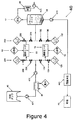
明瞭にするために、加工ライン(30)を通る物質輸送のためのポンプおよび他の手段の位置は、図面から省略されている。必要な数のポンプが到着ラインまたは出発ラインに沿って適用され、それにより、食品(11)は、プロセス要素の他のシーケンスを前述のシーケンスから弁遮断している場合でさえ、プロセス要素の特定のシーケンスを横切ることができる。図4は、弁ならびにポンプの提案された配置および数の表示を含む、図3で開示された一般化された加工ライン(30)の1つの可能な実施形態を詳述し例示する。
図3の例示された加工ライン(30)では、第1の最終ヒータ(13)を備えるシーケンス(I)は、前述の加工ライン(30)およびシーケンス(I)を通過中の食品(11)による汚染に最も脆弱なプロセス要素およびプロセス装置である。したがって、加工ライン(30)の稼働時間は、このプロセス要素(13)を洗浄するのに必要な時間間隔によって決定される。
したがって、第2の最終ヒータ(23)が、加工ライン(30)にさらに設けられ、前述の加工ライン(30)上の前述の第1の最終ヒータ(13)と並列に配置され、これによって、プロセス要素の並列のシーケンス(III)を形成する。加工ライン(30)では、プロセス要素の各シーケンス(I、III)に、弁(133、135、233、235)が設けられている。これによって、プロセス要素のそれぞれのシーケンス(I、III)を、加工ライン(30)の動作中にその並列するシーケンスから弁遮断することができる。第1のシーケンス(I)と並列に、弁(233、235)が、プロセスライン(30)に対して、前述の並列のシーケンス(III)の入口弁(233)としての入口点、および出口弁(235)としての出口点にそれぞれ配置されている。
For clarity, the location of pumps and other means for material transport through the processing line (30) has been omitted from the drawing. The required number of pumps are applied along the arrival or departure line, so that the food (11) identifies the process element even if it is valve-blocking other sequences of process elements from the aforementioned sequence. You can cross the sequence. FIG. 4 details and illustrates one possible embodiment of the generalized processing line (30) disclosed in FIG. 3, including an indication of the proposed arrangement and number of valves and pumps.
In the illustrated processing line (30) of FIG. 3, the sequence (I) with the first final heater (13) is due to the processing line (30) and the food (11) passing through the sequence (I). Process elements and process equipment that are most vulnerable to contamination. Thus, the working time of the processing line (30) is determined by the time interval required to clean this process element (13).
Accordingly, a second final heater (23) is further provided in the processing line (30) and arranged in parallel with the first final heater (13) on the processing line (30), thereby A parallel sequence (III) of process elements is formed. In the processing line (30), valves (133, 135, 233, 235) are provided for each sequence (I, III) of process elements. Thereby, each sequence (I, III) of process elements can be valve-isolated from its parallel sequence during operation of the processing line (30). In parallel with the first sequence (I), the valves (233, 235) are connected to the process line (30) as an inlet point and outlet valve as the inlet valve (233) of the aforementioned parallel sequence (III). It is arrange | positioned at the exit point as (235), respectively.
一般に、本発明の食品加工ラインの特定のシーケンス(I、III)を弁遮断するために、本発明と共に使用することができる特定のタイプの弁に特に重点は置かれない。本発明の重要な態様は、特定のシーケンス(I、III)を、食品加工ラインの動作中に、同一の食品加工ラインと確実に、かつ通常速やかに結合および切断することが可能であることである。
弁は、生産ラインの大きな圧力変動を回避するために、食品加工ライン(30)の動作中に特定のシーケンス(I、III)を速やかに閉じることができることが望ましい場合がある。この趣旨で、下流の弁(135、235)が背圧弁であることが特に好まれる。
上流の弁(133、233)に対して図5で例示的に詳述されるような三方弁(58)は、対になった弁(133、233)および(135、235)を対で置き換えることができる。
しかしながら、図5に関連して以下に記載され、また上述されたように、最終の直接水蒸気インジェクションヒータ(13、23)を確実に適切に機能させ、システムにおける圧力サージを回避するためには、上流の弁(133、233)を単一の三方弁(58)によって置き換えるだけで、弁(135、235)を背圧弁のままにしておくことが一般に好ましい。
In general, no particular emphasis is placed on the particular type of valve that can be used with the present invention to valve shut off a particular sequence (I, III) of the food processing line of the present invention. An important aspect of the present invention is that certain sequences (I, III) can be reliably and normally coupled and disconnected from the same food processing line during operation of the food processing line. is there.
It may be desirable for the valve to be able to quickly close a particular sequence (I, III) during operation of the food processing line (30) to avoid large pressure fluctuations in the production line. For this purpose, it is particularly preferred that the downstream valves (135, 235) are back pressure valves.
A three-way valve (58) as exemplarily detailed in FIG. 5 for the upstream valves (133, 233) replaces the paired valves (133, 233) and (135, 235) in pairs. be able to.
However, as described below in connection with FIG. 5 and described above, in order to ensure proper functioning of the final direct steam injection heater (13, 23) and to avoid pressure surges in the system, It is generally preferred to leave the valves (135, 235) as back pressure valves by simply replacing the upstream valves (133, 233) with a single three-way valve (58).
プロセス要素の2つのシーケンス(I、III)のそれぞれには、プロセス要素のそれぞれの各シーケンス(I、III)上で前述の入口弁(133、233)と出口弁(135、235)との間に配置されたCIP入口弁(134、234)およびCIP出口弁(136、236)がさらに設けられている。これによって、それぞれの入口弁(133、233)および出口弁(135、235)を閉じることによって、それぞれのシーケンス(I、III)を、前述のシーケンス(I、III)が配置された加工ライン(30)から弁遮断すると、プロセス要素の所与のシーケンス(I、III)に対応する、2つのそれぞれのCIP入口弁(134、234)とCIP出口弁(136、236)との間のそれぞれのシーケンス(I、III)に対して定置洗浄手順を実施することができる。 Each of the two sequences of process elements (I, III) includes an inlet valve (133, 233) and an outlet valve (135, 235) on the respective sequence (I, III) of each of the process elements. Are further provided with a CIP inlet valve (134, 234) and a CIP outlet valve (136, 236). Thereby, by closing the respective inlet valves (133, 233) and outlet valves (135, 235), the respective sequences (I, III) are changed into the processing lines (where the aforementioned sequences (I, III) are arranged ( 30) the valve shut off from each of the two CIP inlet valves (134, 234) and CIP outlet valves (136, 236) corresponding to a given sequence (I, III) of process elements A stationary cleaning procedure can be performed on sequence (I, III).
図3の例示的な加工ライン(30)の動作において、上述した例示的な食品滅菌手順を実施する場合、食品(11)は、最初に(予熱後に)、食品(11)をプロセス要素の前述の第1のシーケンス(I)を通過させることによって、第1の最終ヒータ(13)の所望の最終加熱ステップにさらされる。この最終加熱中、並列のシーケンス(III)に含まれる入口弁(233)および出口弁(235)を閉じることによって、食品(11)の、プロセス要素の並列のシーケンス(III)へのアクセスが阻止される。
第1の最終ヒータ(13)でのポンプ輸送可能な食品(11)の加熱中に、ヒータは、汚染され、各加熱プロセスおよび食品(11)に対して個々に決定されなければならない所与の時間の後に、ヒータ(13)は、プロセスによって汚染されてしまうため、汚染された第1の最終ヒータ(13)に対してCIP手順を行うことが必要と考えられる。
In the operation of the exemplary processing line (30) of FIG. 3, when the exemplary food sterilization procedure described above is performed, the food (11) is first (after preheating) and the food (11) is the process element described above. The first final heater (13) is exposed to the desired final heating step by passing through the first sequence (I). During this final heating, closing the inlet valve (233) and outlet valve (235) included in the parallel sequence (III) prevents food (11) from accessing the parallel sequence (III) of process elements. Is done.
During heating of the pumpable food (11) with the first final heater (13), the heater becomes contaminated and must be determined individually for each heating process and food (11). After time, the heater (13) will be contaminated by the process, so it is considered necessary to perform a CIP procedure on the contaminated first final heater (13).
ここで、定置洗浄のために加工ライン(30)全体をシャットダウンするのではなく、第1の最終ヒータ(13)を備えるプロセス要素の第1のシーケンス(I)のみを、プロセス要素の第1のシーケンス(I)に含まれるそれぞれの入口弁(133)および出口弁(135)を閉じることによって、CIP手順のためにシャットダウンする。これは、プロセス要素の並列のシーケンス(III)に含まれるそれぞれの入口弁(233)および出口弁(235)を開くことによって、(第1のシーケンス(I)のCIP中に)クーラ(14)までプロセス要素の並列のシーケンス(III)を介して食品(11)を代わりに通過させている間に行われる。 Here, instead of shutting down the entire processing line (30) for in-place cleaning, only the first sequence (I) of process elements comprising the first final heater (13) is used for the first of the process elements. Shut down for the CIP procedure by closing each inlet valve (133) and outlet valve (135) included in sequence (I). This is done by opening each inlet valve (233) and outlet valve (235) included in the parallel sequence (III) of process elements (during CIP of the first sequence (I)) the cooler (14) Until the food (11) is instead passed through the parallel sequence (III) of process elements.
第1のシーケンス(I)が加工ライン(30)の物質流から切断されている間の定置洗浄は、CIP入口弁(134)を開くことによってCIP入口(131)を通して洗浄剤およびフラッシング剤が第1のシーケンス(I)に入ることを可能にすることによって、ならびにCIP出口弁(136)を開くことによってCIP出口(132)を通して洗浄剤が第1のシーケンス(I)を出ることを可能にすることによって、当技術分野で通常のやり方で遂行される。洗浄の後、CIP入口(134)およびCIP出口(136)弁は、閉じられ、したがって、CIPシステムを加工ライン(30)および第1のシーケンス(I)からもう一度隔離する。 In-situ cleaning while the first sequence (I) is being cut from the material flow in the processing line (30) is a process in which cleaning and flushing agents are passed through the CIP inlet (131) by opening the CIP inlet valve (134). Allowing the detergent to exit the first sequence (I) through the CIP outlet (132) by allowing it to enter one sequence (I) and by opening the CIP outlet valve (136) And is performed in the usual manner in the art. After cleaning, the CIP inlet (134) and CIP outlet (136) valves are closed, thus again isolating the CIP system from the processing line (30) and the first sequence (I).
したがって、プロセス要素、特に第1の最終ヒータ(13)の第1のシーケンス(I)が、選択されたCIP手順によって十分に洗浄されると、プロセス要素の並列のシーケンス(III)が、第1のシーケンス(I)について記載されたのと同一のやり方で加工ライン(30)を通る食品(11)の物質流から切断され、続いて、上記のようなCIPにかけられ得る。その後すぐに、並列のシーケンス(III)を、加工ライン(30)を通る食品の物質流に結合させるための上記の手順に従って、第1のシーケンス(I)を再び物質流に結合させることができる。加工ライン(30)の設計に応じて、第2の最終ヒータ(23)および並列のシーケンス(III)は、第1のシーケンス(I)および第1の最終ヒータ(13)がCIPを受けるのに十分な時間だけ動作することができ、または、プロセス要素の2つのシーケンス(I、III)は、各シーケンス(I、III)が加工ライン(30)の稼働時間の50%動作するように、加工ライン(30)の作業負荷を最大で均等分担まで分担することができる。
上記の詳細な方法に従って加工ライン(30)を動作させる効果は、加工ライン(30)の全体的な稼働時間が、もはや最短の稼働時間を有するプロセス要素および/または加工装置に依存せず、むしろ最短の稼働時間を有するプロセス要素および/または加工装置と比較して、より長い、通常はるかに長い稼働時間を有するプロセス要素および/または加工装置に依存するようになるということである。
Thus, once the process element, in particular the first sequence (I) of the first final heater (13), has been sufficiently cleaned by the selected CIP procedure, the parallel sequence (III) of process elements is the first Can be cut from the material stream of the food product (11) through the processing line (30) in the same manner as described for sequence (I), and subsequently subjected to CIP as described above. Immediately thereafter, the first sequence (I) can be re-coupled to the mass flow according to the procedure described above for coupling the parallel sequence (III) to the mass flow of food through the processing line (30). . Depending on the design of the processing line (30), the second final heater (23) and the parallel sequence (III) may cause the first sequence (I) and the first final heater (13) to receive CIP. Can operate for a sufficient amount of time, or two sequences of process elements (I, III) can be processed so that each sequence (I, III) operates 50% of the working time of the processing line (30) It is possible to share the work load of the line (30) up to even sharing.
The effect of operating the processing line (30) according to the above detailed method is that the overall operating time of the processing line (30) no longer depends on the process elements and / or processing equipment having the shortest operating time, rather In comparison to process elements and / or processing equipment having the shortest uptime, it becomes dependent on longer, usually much longer uptime process elements and / or processing equipment.
本発明の例示された食品加工ライン(30)では、フラッシュクーラ(14)が、2つの前述のシーケンス(I、III)が、1つのプロセスラインに再結合された後に配置され、フラッシュクーラ(14)が、蒸気出口(17)および処理された製品(15)の出口を有する。フラッシュクーラ(14)は、典型的には最終ヒータが低温殺菌温度で動作しているときに、冷却のための熱交換器と置き換えることができ、または、フラッシュクーラ(14)からの処理された製品の出口温度が、包装には高すぎる場合には、熱交換器の形態のさらなるクーラで増強されてもよい。この後者の実施形態は、食品(11)を滅菌する場合に一般的であり、実施例において本発明の概念を試験するために使用される本発明の特定の実施形態に対して図5で例示される。
図4および図5は、本発明の一般化された食品加工ライン(30)の特定の実施形態を詳述し、食品加工ライン(40、50)が、液状食品(11)の処理のための食品加工ラインを低温殺菌(40)または滅菌(40、50)しており、図4の食品加工ラインは、両方を行うことができる。
In the illustrated food processing line (30) of the present invention, the flash cooler (14) is placed after the two aforementioned sequences (I, III) are recombined into one process line, and the flash cooler (14 ) Has a vapor outlet (17) and an outlet for the treated product (15). The flash cooler (14) can be replaced with a heat exchanger for cooling, typically when the final heater is operating at pasteurization temperature, or processed from the flash cooler (14). If the outlet temperature of the product is too high for the packaging, it may be augmented with a further cooler in the form of a heat exchanger. This latter embodiment is typical when sterilizing food (11) and is illustrated in FIG. 5 for a particular embodiment of the invention used in the examples to test the inventive concept. Is done.
4 and 5 detail a specific embodiment of the generalized food processing line (30) of the present invention, where the food processing line (40, 50) is for processing liquid food (11). The food processing line is pasteurized (40) or sterilized (40, 50), and the food processing line of FIG. 4 can do both.
図4の設定では、液状食品(11)は、供給タンク(41)に含まれ、ここから例えば、管状または板状の熱交換器の形態の間接ヒータ(42)にポンプ(471)輸送される。任意選択で、間接ヒータ(42)の後に、ブースタポンプ(472)を配置することができる。間接ヒータ(42)の後の食品加工ライン(40)上の点で、存在する場合は、任意選択のブースタポンプ(472)の後で、食品加工ライン(40)は、前述のプロセス要素の並列のシーケンス(I、III)に分割され、各シーケンスを上で詳述したように弁(133、135、233、235)開閉することができる。上で詳述したようなCIPの入口弁(134、234)および出口弁(136、236)が、上記のようなそれぞれのシーケンス(I、III)上にさらに設けられている。 In the setting of FIG. 4, the liquid food (11) is contained in the supply tank (41) and is pumped (471) from here to, for example, an indirect heater (42) in the form of a tubular or plate heat exchanger. . Optionally, a booster pump (472) can be placed after the indirect heater (42). At a point on the food processing line (40) after the indirect heater (42), if present, after the optional booster pump (472), the food processing line (40) is connected in parallel with the aforementioned process elements. And the valves (133, 135, 233, 235) can be opened and closed as detailed above. A CIP inlet valve (134, 234) and outlet valve (136, 236) as detailed above are further provided on each sequence (I, III) as described above.
食品加工ライン(40)が低温殺菌食品加工ラインであるとき、間接ヒータ(42)は、食品(11)を低温殺菌温度ではない第1の温度に加熱し、食品加工ライン(40)が滅菌食品加工ラインであるとき、間接ヒータ(42)は、食品を好ましくは低温殺菌温度である第1の温度に加熱する。食品加工ライン(40)が低温殺菌食品加工ライン(40)であるとき、最終ヒータ(13、23)は、通常管状または板状熱交換器、例えば、切削された(scraped)板状熱交換器であり、食品加工ライン(40)が滅菌食品加工ライン(40)であるとき、最終ヒータ(13、23)は、直接水蒸気ヒータであり、特にインジェクション(直接水蒸気インジェクション、DSIインジェクション)またはインフュージョン(直接水蒸気インフュージョン)直接水蒸気ヒータが好まれ、その両方の選択肢が好まれる。 When the food processing line (40) is a pasteurized food processing line, the indirect heater (42) heats the food (11) to a first temperature that is not the pasteurized temperature, and the food processing line (40) is a sterilized food. When in the processing line, the indirect heater (42) heats the food to a first temperature, preferably a pasteurization temperature. When the food processing line (40) is a pasteurized food processing line (40), the final heater (13, 23) is usually a tubular or plate heat exchanger, for example, a crushed plate heat exchanger. When the food processing line (40) is a sterilized food processing line (40), the final heaters (13, 23) are direct steam heaters, particularly injection (direct steam injection, DSI injection) or infusion ( Direct steam infusion) Direct steam heaters are preferred, both options being preferred.
フラッシュクーラ(44)は、上で詳述したように、2つのシーケンス(I、III)が再結合された後に配置される。蒸気(17)は、フラッシュクーラ(44)から凝縮器(46)に導かれ、さらなる使用のためにポンプ(474)輸送され、または廃棄物として処分され、一方処理された製品(15)は、食品加工ライン(40)を出る前に間接クーラ(441)を介して充填ステーション(45)にポンプ(473)輸送される。
図4に例示された食品加工ライン(40)は、食品(11)、特にミルク、ジュース、豆乳またはそのような類似の製品を滅菌するのに特に適切である。しかし、上で詳述したように、プロセス装置のわずかな変更で、食品加工ライン(40)は、食品加工ライン(40)に対して本発明の方法を実行しながら食品(11)を低温殺菌するのに等しく適切になる。
図5は、以下に記載される実験を行なうために使用された食品加工ライン(50)について詳述する。明瞭にするために、CIPシステムおよびCIP入口弁(134、234)は、詳述されていないが、これらは、図3および図4に詳述された通りである。
The flash cooler (44) is placed after the two sequences (I, III) are recombined as detailed above. Steam (17) is directed from the flash cooler (44) to the condenser (46) and pumped (474) for further use or disposed of as waste, while the processed product (15) is Before leaving the food processing line (40), it is pumped (473) to the filling station (45) via an indirect cooler (441).
The food processing line (40) illustrated in FIG. 4 is particularly suitable for sterilizing food (11), in particular milk, juice, soy milk or similar products. However, as detailed above, with a slight modification of the process equipment, the food processing line (40) may pasteurize the food (11) while performing the method of the present invention on the food processing line (40). Equally appropriate to do.
FIG. 5 details the food processing line (50) used to perform the experiments described below. For clarity, the CIP system and CIP inlet valves (134, 234) have not been detailed, but are as detailed in FIGS.
図では、食品(11)、実験では脱脂乳は、滅菌に先立って任意選択の供給タンク(51)に保持される。任意選択の供給タンクから、食品(11)は、プレヒータ(52)へポンプ輸送され(571)、このプレヒータが、本例および実験では、食品をミルクに対する低温殺菌温度(75℃)に加熱し、これによって続く滅菌加熱のためのミルクを用意する。三方弁(58)によって、2つのそれぞれのシーケンス(I、III)への入口点として図3および図4に詳述された2つの個々の弁(133、233)を置き換えた。シーケンス(I、III)では、本実施形態の最終ヒータ(13)は、直接水蒸気インフュージョンヒータ(13a)(APV即時インフュージョン、国際公開第96/16556号参照)と続く保持セル(13b)との複合体であり、実験のミルクに対する保持時間の合計が、実際の滅菌に対して146℃で約7秒である。ボール弁(136、236)は、実験で使用されたCIP液体の出口点を表し、2つの背圧弁(135、235)が前述のシーケンス(I、III)を完了し、食品加工ライン(50)を再結合する。上で詳述したように、一般に弁(135、235)として背圧弁を使用することが好まれ、さらに、本実施形態のように、三方弁(58)が使用される場合、これが推奨される。 In the figure, food (11), in the experiment skim milk, is held in an optional supply tank (51) prior to sterilization. From an optional supply tank, food (11) is pumped (571) to a preheater (52), which in this example and experiment heats the food to a pasteurization temperature for milk (75 ° C), This prepares milk for subsequent sterilization heating. A three-way valve (58) replaced the two individual valves (133, 233) detailed in FIGS. 3 and 4 as entry points to the two respective sequences (I, III). In the sequence (I, III), the final heater (13) of the present embodiment includes a direct steam infusion heater (13a) (APV immediate infusion, see WO96 / 16556) and a holding cell (13b) that follows. The total retention time for the experimental milk is about 7 seconds at 146 ° C. for actual sterilization. The ball valves (136, 236) represent the exit point of the CIP liquid used in the experiment, and the two back pressure valves (135, 235) complete the aforementioned sequence (I, III) and the food processing line (50) Recombine. As detailed above, it is generally preferred to use a back pressure valve as the valve (135, 235), and this is recommended when a three-way valve (58) is used as in this embodiment. .
実験で用いられた高い滅菌温度(146℃)のために、フラッシュクーラ(54)は、任意選択ではあるが一対の後続する間接クーラ(541、542)、およびフラッシュクーラ(54)における圧力損失後に必要な流量を提供するためにフラッシュクーラ(54)の直後に配置された遠心ポンプ(573)で増強された。フラッシュクーラ(54)は、ミルクを約64℃に冷却し、後続の間接クーラ(541、542)は、最終製品温度、本実験では20℃に冷却する。滅菌された食品(15)をいつでも使用できる形態で消費者に送出するために、任意選択の充填ステーション(55)が食品加工ライン(50)の端部に配置され、こうして食品加工ライン(50)を完了する。 Because of the high sterilization temperature used in the experiment (146 ° C.), the flash cooler (54) is optional but after a pressure drop in a pair of subsequent indirect coolers (541, 542), and the flash cooler (54). It was augmented with a centrifugal pump (573) located immediately after the flash cooler (54) to provide the required flow rate. The flash cooler (54) cools the milk to about 64 ° C and the subsequent indirect coolers (541, 542) cool the final product temperature, 20 ° C in this experiment. An optional filling station (55) is placed at the end of the food processing line (50) to deliver the sterilized food (15) to the consumer in a ready-to-use form, thus the food processing line (50). To complete.
一般に、供給タンク(51)および間接クーラ(541、542)は、図5のプロセスライン(50)では任意選択である。ラインにおけるこれらの存在は、特に2つの間接クーラの使用に関しては、本実験で使用されたパイロットプラントの設定を反映し、実験で使用するためのパイロットサイトで利用可能な熱交換器を反映する。生産において、フラッシュ冷却能力、および任意選択の間接クーラとの組合せは、ミルクまたはジュースなどの過熱された水性食品を冷却する場合、当業者に知られているやり方で生産能力および設置面積を最適化するように調整されてもよい。 In general, the supply tank (51) and the indirect coolers (541, 542) are optional in the process line (50) of FIG. Their presence in the line, particularly with respect to the use of two indirect coolers, reflects the pilot plant settings used in this experiment and reflects the heat exchangers available at the pilot site for use in the experiment. In production, the combination of flash cooling capacity and optional indirect cooler optimizes production capacity and footprint in a manner known to those skilled in the art when cooling superheated aqueous food products such as milk or juice It may be adjusted to.
そのようなものとして、上記の実施形態に加えて、本明細書に開示された発明は、さらなる実施形態に関する。定置洗浄手順中に食品加工ライン(30)を動作させる方法は、
a)複数の連続して流体接続されたプロセス要素(12、13、23、14)を備える食品加工ライン(30)を設けるステップであって、複数のプロセス要素(13、23)の少なくとも第1および第2のプロセス要素が実質的に同様である、ステップと、
b)食品(11)が食品加工ライン(30)および複数の連続して流体接続されたプロセス要素(12、13、23、14)を物質流として横切ることができるように食品加工ライン(30)を配置し、これによって食品処理プロセスにおいて食品(11)を処理された製品(15)に変換するステップと、
c)プロセス要素の第1のシーケンス(I)上に複数の連続して流体接続されたプロセス要素(12、13、23、14)のうちの少なくとも1つの第1のプロセス要素(13)を配置するステップであって、第1のシーケンス(I)が第1のシーケンス(I)への入口点に配置された入口弁(133)および第1のシーケンス(I)への出口点に配置された出口弁(135)をさらに備え、少なくとも1つの第1のプロセス要素(13)が、入口弁(133)と出口弁(135)との間に配置され、入口弁および出口弁(133、135)の配置が、入口弁および出口弁(133、135)を開閉することによって、第1のシーケンス(I)を、食品加工ライン(30)の動作中に食品加工ライン(30)および食品(11)の物質流に対して弁開閉することができるように食品加工ライン(30)上に配置されている、ステップと、
d)プロセス要素の並列のシーケンス(III)上に複数の連続して流体接続されたプロセス要素(12、13、23、14)のうちの少なくとも1つの第2のプロセス要素(23)を配置するステップであって、並列のシーケンス(III)が並列のシーケンス(III)への入口点に配置された入口弁(233)および並列のシーケンス(III)への出口点に配置された出口弁(235)をさらに備え、少なくとも1つの第2のプロセス要素(23)が、入口弁(233)と出口弁(235)との間に配置され、入口弁および出口弁(233、235)の配置が、入口弁および出口弁(233、235)を開閉することによって、並列のシーケンス(III)を、食品加工ライン(30)の動作中に食品加工ライン(30)および食品(11)の物質流に対して弁開閉することができるように食品加工ライン(30)上に配置されている、ステップと、
e)プロセス要素の第1のシーケンス(I)およびプロセス要素の並列のシーケンス(III)を食品加工ライン(30)上に並列に配置し、それにより、食品加工ライン(30)の動作中の食品(11)の物質流が、シーケンス(I、III)の一方を食品加工ライン(30)から弁遮断したときに、もう一方を通ることができる、ステップと、
f)それぞれの各シーケンス(I、III)上の入口弁(133、233)と出口弁(135、235)との間で、プロセス要素の各シーケンス(I、III)上にそれぞれ配置されたCIP入口弁(134、234)およびCIP出口弁(136、236)を、プロセス要素の2つのシーケンス(I、III)のそれぞれにさらに設けるステップであって、それぞれの第1または第2のプロセス要素(13、23)がそれぞれのCIP入口弁(134、234)とそれぞれのCIP出口弁(136、236)との間に配置されている、ステップと、を含み、
本方法は、
g)食品加工ライン(30)上で食品処理プロセスを実行する前に、プロセス要素の並列のシーケンス(III)を食品加工ライン(30)から弁遮断し、プロセス要素の第1のシーケンス(I)を食品(11)の物質流を通過させるために開放したままにしておくステップと、
h)食品加工ライン(30)上で食品処理プロセスを実行し、これによって食品処理プロセスにおいて食品(11)を処理された製品(15)に変換するステップと、
i)食品処理プロセスを実行した時間の後に、食品処理プロセスの実行中に同時に、物質流を第1のシーケンス(I)の通過から並列のシーケンス(III)の通過へ切替え、これによって、第1のシーケンス(I)を食品加工ライン(30)から弁遮断し、同時に、並列のシーケンス(III)を食品加工ライン(30)に開放することによって、第1のシーケンス(I)を、食品処理プロセスの実行中に同時に、食品加工ライン(30)の並列のシーケンス(III)に置き換えるステップと、
j)第1のシーケンス(I)を食品加工ライン(30)から弁遮断している間に、第1のシーケンス(I)に対する定置洗浄手順を実行するステップと、をさらに含む。
一実施形態において、食品加工ライン(30)が停止されるまでおよび/または食品処理プロセスが終了するまで、ステップi)およびj)が繰り返される方法。
一実施形態において、食品加工ライン(30)が120℃を上回る温度で食品を処理または滅菌するための熱処理システムである方法。
一実施形態において、食品加工ライン(30)において、食品(11)が、第1または並列のシーケンス(I、III)のいずれかで高温処理にかけられる前に最初にプレヒータ(12)で予熱される方法。
一実施形態において、複数のプロセス要素(13、23)の第1のプロセス要素および第2のプロセス要素が、第1の最終ヒータ(13)および第2の最終ヒータ(23)である方法。
As such, in addition to the embodiments described above, the invention disclosed herein relates to further embodiments. The method of operating the food processing line (30) during the stationary cleaning procedure is:
a) providing a food processing line (30) comprising a plurality of consecutively fluidly connected process elements (12, 13, 23, 14), wherein at least a first of the plurality of process elements (13, 23); And the second process element is substantially similar; and
b) The food processing line (30) so that the food product (11) can traverse the food processing line (30) and a plurality of continuously fluidly connected process elements (12, 13, 23, 14) as a material flow. And thereby converting food (11) into processed product (15) in a food processing process;
c) disposing at least one first process element (13) of a plurality of consecutively fluidly connected process elements (12, 13, 23, 14) on a first sequence (I) of process elements; A first sequence (I) arranged at an inlet valve (133) arranged at an inlet point to the first sequence (I) and an outlet point into the first sequence (I) An outlet valve (135) is further provided, and at least one first process element (13) is disposed between the inlet valve (133) and the outlet valve (135), and the inlet and outlet valves (133, 135). The arrangement of the first sequence (I) by opening and closing the inlet and outlet valves (133, 135) causes the food processing line (30) and the food (11) to operate during operation of the food processing line (30). Against material flow To Te valve closing is arranged on food processing line (30) to allow the steps,
d) placing at least one second process element (23) of the plurality of consecutively fluidly connected process elements (12, 13, 23, 14) on a parallel sequence (III) of process elements An inlet valve (233) arranged at the entry point to the parallel sequence (III) and an outlet valve (235 arranged at the exit point to the parallel sequence (III). At least one second process element (23) is disposed between the inlet valve (233) and the outlet valve (235), and the arrangement of the inlet and outlet valves (233, 235) is: By opening and closing the inlet and outlet valves (233, 235), a parallel sequence (III) is made during the operation of the food processing line (30) and the food processing line (30) and food. Is disposed on the food processing line (30) to be able to valve against material flow 11), comprising the steps,
e) A first sequence of process elements (I) and a parallel sequence of process elements (III) are placed in parallel on the food processing line (30), so that the food in operation of the food processing line (30) A flow of material in (11) can pass through one of the sequences (I, III) when the valve is shut off from the food processing line (30);
f) a CIP located on each sequence (I, III) of process elements between the inlet valve (133, 233) and the outlet valve (135, 235) on each sequence (I, III). Providing an inlet valve (134, 234) and a CIP outlet valve (136, 236) in each of the two sequences (I, III) of process elements, each of the first or second process elements ( 13, 23) are disposed between each CIP inlet valve (134, 234) and each CIP outlet valve (136, 236), and
This method
g) Prior to performing a food processing process on the food processing line (30), the parallel sequence (III) of process elements is valved off from the food processing line (30) and the first sequence of process elements (I) Leaving open to pass the substance stream of food (11);
h) performing a food processing process on the food processing line (30), thereby converting the food (11) into a processed product (15) in the food processing process;
i) After the time of executing the food processing process, simultaneously during the execution of the food processing process, the material flow is switched from passing through the first sequence (I) to passing through the parallel sequence (III), whereby the first The first sequence (I) can be cut off from the food processing line (30) while simultaneously opening the parallel sequence (III) to the food processing line (30). Simultaneously replacing the parallel processing sequence (III) of the food processing line (30) during the execution of
j) performing a stationary cleaning procedure for the first sequence (I) while valve-closing the first sequence (I) from the food processing line (30).
In one embodiment, the method wherein steps i) and j) are repeated until the food processing line (30) is stopped and / or the food processing process is terminated.
In one embodiment, the method wherein the food processing line (30) is a heat treatment system for processing or sterilizing food at a temperature above 120 ° C.
In one embodiment, in the food processing line (30), the food (11) is first preheated with a preheater (12) before being subjected to high temperature treatment in either the first or parallel sequence (I, III). Method.
In one embodiment, the method wherein the first process element and the second process element of the plurality of process elements (13, 23) are a first final heater (13) and a second final heater (23).
一実施形態において、第1の最終ヒータ(13)および第2の最終ヒータ(23)が、両方とも直接水蒸気ヒータであり、食品加工ライン(30)が、第1の最終ヒータおよび第2の最終ヒータ(13、23)の後の食品加工ライン(30)上に配置された少なくとも1つのフラッシュクーラ(14)をさらに備える方法。 In one embodiment, the first final heater (13) and the second final heater (23) are both direct steam heaters and the food processing line (30) is the first final heater and the second final heater. The method further comprising at least one flash cooler (14) disposed on the food processing line (30) after the heaters (13, 23).
図3および図4に開示されるような本発明の好ましい実施形態において、
a)複数の連続して流体接続されたプロセス要素(12、13、23、14)を備える食品加工ライン(30)を設けるステップであって、複数の連続して流体接続されたプロセス要素(12、13、23、14)が、プレヒータ(12)、第1の直接水蒸気ヒータ(13)、第2の直接水蒸気ヒータ(23)、およびフラッシュクーラ(14)を備え、直接水蒸気ヒータ(13、23)が実質的に同様であり、プレヒータ(12)、直接水蒸気ヒータ(13、23)、およびフラッシュクーラ(14)が、食品加工ライン(30)上に連続して配置され、直接水蒸気ヒータ(13、23)がプレヒータ(12)の後であるがフラッシュクーラ(14)の前に配置されている、ステップと、
b)ミルク派生品(11)が物質流として食品加工ライン(30)および複数の連続して流体接続されたプロセス要素(12、13、23、14)を横切ることができるように食品加工ライン(30)を配置し、これによって高温のミルク派生品滅菌プロセスにおいてミルク派生品(11)を熱処理されたミルク派生品(15)に変換するステップと、
c)第1の直接水蒸気ヒータ(13)をプロセス要素の第1のシーケンス(I)上に配置するステップであって、第1のシーケンス(I)が第1のシーケンス(I)への入口点に配置された入口弁(133)および第1のシーケンス(I)への出口点に配置された出口弁(135)をさらに備え、第1の直接水蒸気ヒータ(13)が、入口弁(133)と出口弁(135)との間に配置され、入口弁および出口弁(133、135)の配置が、入口弁および出口弁(133、135)を開閉することによって、第1のシーケンス(I)を、食品加工ライン(30)の動作中に食品加工ライン(30)およびミルク派生品(11)の物質流に対して弁開閉することができるように食品加工ライン(30)上に配置されている、ステップと、
d)第2の直接水蒸気ヒータ(23)をプロセス要素の並列のシーケンス(III)上に配置するステップであって、並列のシーケンス(III)が、並列のシーケンス(III)への入口点に配置された入口弁(233)および並列のシーケンス(III)への出口点に配置された出口弁(235)をさらに備え、第2の直接水蒸気ヒータ(23)が、入口弁(233)と出口弁(235)との間に配置され、入口弁および出口弁(233、235)の配置が、入口弁および出口弁(233、235)を開閉することによって、並列のシーケンス(III)を、食品加工ライン(30)の動作中に食品加工ライン(30)およびミルク派生品(11)の物質流に対して弁閉鎖し、再び開放することができるように食品加工ライン(30)上に配置されている、ステップと、
e)プロセス要素の第1のシーケンス(I)およびプロセス要素の並列のシーケンス(III)を食品加工ライン(30)上に並列に配置し、それにより、食品加工ライン(30)の動作中のミルク派生品(11)の物質流が、シーケンス(I、III)の一方を食品加工ライン(30)から弁遮断したときに、もう一方を通ることができる、ステップと、
f)それぞれの各シーケンス(I、III)上の入口弁(133、233)と出口弁(135、235)との間で、プロセス要素の各シーケンス(I、III)上にそれぞれ配置されたCIP入口弁(134、234)およびCIP出口弁(136、236)を、プロセス要素の2つのシーケンス(I、III)のそれぞれにさらに設けるステップであって、それぞれの第1または第2の直接水蒸気ヒータ(13、23)がそれぞれのCIP入口弁(134、234)とそれぞれのCIP出口弁(136、236)との間に配置されている、ステップと、
を含む定置洗浄手順中に食品加工ライン(30)を動作させる方法が開示され、
本方法は、
g)食品加工ライン(30)上で高温のミルク派生品滅菌プロセスを実行する前に、プロセス要素の並列のシーケンス(III)を食品加工ライン(30)から弁遮断し、プロセス要素の第1のシーケンス(I)をミルク派生品(11)の物質流を通過させるために開放したままにしておくステップと、
h)食品加工ライン(30)上で高温のミルク派生品滅菌プロセスを実行し、これによって高温のミルク派生品滅菌プロセスにおいてミルク派生品(11)を熱処理されたミルク派生品(15)に変換するステップと、
i)高温のミルク派生品滅菌プロセスを実行した時間の後に、高温のミルク派生品滅菌プロセスの実行中に同時に、物質流を第1のシーケンス(I)の通過から並列のシーケンス(III)の通過へ切替え、これによって、第1のシーケンス(I)を食品加工ライン(30)から弁遮断し、同時に、並列のシーケンス(III)を食品加工ライン(30)に開放することによって、第1のシーケンス(I)を、高温のミルク派生品滅菌プロセスの実行中に同時に、食品加工ライン(30)の並列のシーケンス(III)に置き換えるステップと、
j)第1のシーケンス(I)を食品加工ライン(30)から弁遮断している間に、第1のシーケンス(I)に対する定置洗浄手順を実行するステップと、
をさらに含む。
図6および図7は、本発明の概念のさらなる発展形態を詳述する。
In a preferred embodiment of the invention as disclosed in FIGS. 3 and 4,
a) providing a food processing line (30) comprising a plurality of continuously fluidly connected process elements (12, 13, 23, 14) comprising a plurality of continuously fluidly connected process elements (12) , 13, 23, 14) includes a pre-heater (12), a first direct steam heater (13), a second direct steam heater (23), and a flash cooler (14), and the direct steam heater (13, 23). ) Is substantially the same, and the preheater (12), the direct steam heater (13, 23), and the flash cooler (14) are continuously arranged on the food processing line (30), and the direct steam heater (13 23) is arranged after the preheater (12) but before the flash cooler (14),
b) the food processing line (11) so that the milk derivative (11) can traverse the food processing line (30) and a plurality of continuously fluidly connected process elements (12, 13, 23, 14) as a substance stream. 30), thereby converting the milk derivative (11) to the heat treated milk derivative (15) in a hot milk derivative sterilization process;
c) placing the first direct steam heater (13) on the first sequence (I) of process elements, wherein the first sequence (I) is the entry point to the first sequence (I) And an outlet valve (135) located at the outlet point to the first sequence (I), wherein the first direct steam heater (13) is connected to the inlet valve (133). Between the inlet valve and the outlet valve (135), the arrangement of the inlet valve and outlet valve (133, 135) opens and closes the first sequence (I) by opening and closing the inlet valve and outlet valve (133, 135). Placed on the food processing line (30) so that it can be opened and closed against the material flow of the food processing line (30) and the milk derivative (11) during operation of the food processing line (30). Step, and
d) placing a second direct steam heater (23) on the parallel sequence (III) of process elements, the parallel sequence (III) being placed at the entry point to the parallel sequence (III) And an outlet valve (235) located at the outlet point to the parallel sequence (III), the second direct steam heater (23) is connected to the inlet valve (233) and the outlet valve (235), and the arrangement of the inlet and outlet valves (233, 235) opens and closes the inlet and outlet valves (233, 235), thereby allowing the parallel sequence (III) to be processed in food processing. On the food processing line (30) so that it can be closed against the material flow of the food processing line (30) and the milk derivative (11) and reopened during operation of the line (30). It is arranged, and the step,
e) placing the first sequence of process elements (I) and the parallel sequence of process elements (III) in parallel on the food processing line (30) so that the milk in operation of the food processing line (30) A flow of the derivative (11) can pass through one of the sequences (I, III) when the valve is shut off from the food processing line (30);
f) a CIP located on each sequence (I, III) of process elements between the inlet valve (133, 233) and the outlet valve (135, 235) on each sequence (I, III). Further comprising an inlet valve (134, 234) and a CIP outlet valve (136, 236) in each of the two sequences (I, III) of process elements, each of the first or second direct steam heaters (13, 23) being disposed between each CIP inlet valve (134, 234) and each CIP outlet valve (136, 236);
A method of operating a food processing line (30) during a stationary cleaning procedure comprising:
This method
g) Before performing the hot milk derivative sterilization process on the food processing line (30), the parallel sequence of process elements (III) is valve-shut off from the food processing line (30) and the first of the process elements Leaving sequence (I) open to pass the substance stream of milk derivative (11);
h) performing a hot milk derivative sterilization process on the food processing line (30), thereby converting the milk derivative (11) into a heat treated milk derivative (15) in the hot milk derivative sterilization process; Steps,
i) After the time of performing the hot milk derivative sterilization process, simultaneously during the execution of the hot milk derivative sterilization process, the material flow is passed from the first sequence (I) through the parallel sequence (III). Thereby switching off the first sequence (I) from the food processing line (30) and simultaneously opening the parallel sequence (III) to the food processing line (30). Replacing (I) with a parallel sequence (III) of the food processing line (30) simultaneously during execution of the hot milk derivative sterilization process;
j) performing a stationary cleaning procedure for the first sequence (I) while valve-closing the first sequence (I) from the food processing line (30);
Further included.
6 and 7 detail further developments of the inventive concept.
図6は、生産ライン(60)上に、それぞれの第1および並列のシーケンス(I、III)と並列に配置されたさらなるシーケンス(IV)を備える、上に詳述されたような生産ライン(60)を詳述し、さらなるシーケンス(IV)が、入口弁(337)および出口弁(339)、ならびにそれらの間に配置されたCIP入口弁(334)およびCIP出口弁(336)、ならびにCIP入口弁とCIP出口弁との間に配置された最終ヒータ3(33)を備える。図6に詳述されているような設定は、洗浄時間が汚染時間よりも長く、2つの並列のシーケンス(I、III)が連続した動作を保証することができないような場合に有用である。しかしながら、動作において、一般に良く設計された生産プラントでは、洗浄時間は、汚染時間よりも常に短い。 FIG. 6 shows a production line (as detailed above) comprising a further sequence (IV) arranged in parallel with each first and parallel sequence (I, III) on the production line (60). 60) and further sequence (IV) includes an inlet valve (337) and an outlet valve (339), and a CIP inlet valve (334) and a CIP outlet valve (336) disposed therebetween, and CIP A final heater 3 (33) is provided between the inlet valve and the CIP outlet valve. A setting as detailed in FIG. 6 is useful when the cleaning time is longer than the contamination time and the two parallel sequences (I, III) cannot guarantee continuous operation. However, in operation, in a generally well-designed production plant, the cleaning time is always shorter than the contamination time.
しかしながら、図7は、図6に詳述されたシステムの改善された使用を詳述する。前述したように、洗浄時間は、汚染までの時間よりも通常短く、著しく短くさえある。以下の実験では、試験設定の洗浄時間は25分の生産実行後に90秒であったため、最終ヒータの能力を倍増することによって、1つまたは両方の最終ヒータ(13、23)の利用率の低下につながる可能性がある。したがって、2つの生産ライン(I、V)が共通の並列のシーケンス(III)を共有することが有利な場合があり、これによって共通の並列のシーケンス(III)の負荷時間が増加する。例えば、2つの最終ヒータ(13、23)が両方ともセパレータ(18)のために常時オンライン状態を維持しなければならない国際公開第2004/077968号に詳述された生産ライン(20)では、共通の並列のシーケンス(III)を共有することは、最終ヒータ(13、23)の一方のCIP中に、このタイプの滅菌生産ラインの継続的な動作も可能にする。 However, FIG. 7 details the improved use of the system detailed in FIG. As mentioned above, the cleaning time is usually shorter and even significantly shorter than the time to contamination. In the following experiment, the test setup cleaning time was 90 seconds after a 25 minute production run, thus reducing the utilization of one or both final heaters (13, 23) by doubling the capacity of the final heater. May lead to Thus, it may be advantageous for two production lines (I, V) to share a common parallel sequence (III), which increases the load time of the common parallel sequence (III). For example, in the production line (20) detailed in WO 2004/079968, where two final heaters (13, 23) must both be kept online for the separator (18) at all times, This parallel sequence (III) also allows for continuous operation of this type of sterile production line during one CIP of the final heater (13, 23).
一方の最終ヒータが高い乾物含量を有するジュースの一部を受け取り、もう一方が、低い乾物含量を有するジュースの一部を受け取る国際公開第2004/077968号の生産ラインに対しては、高い乾物含量を有する一部を受け取る最終ヒータは、もう一方のヒータよりも頻繁に洗浄を必要とすることが予想される傾向にある。
しかしながら、図7に詳述された設定は、容易にこれにも適応することができる。そのような共有された設定では、2つの生産ライン(I、V)の処理温度が異なる温度を必要とする場合に、プレヒータ(12、32)は、異なることができ、または、システム要件が許せば、それらを単一ユニットへ組み合わせることができる。
For the production line of WO 2004/077968 where one final heater receives a part of juice with a high dry matter content and the other receives a part of juice with a low dry matter content, a high dry matter content The final heater that receives a portion having a tendency to be expected to require cleaning more frequently than the other heater.
However, the settings detailed in FIG. 7 can easily be adapted to this as well. In such a shared setting, if the processing temperatures of the two production lines (I, V) require different temperatures, the preheaters (12, 32) can be different or allow system requirements. They can be combined into a single unit.
したがって、本発明によると、
− 前記食品滅菌ライン(40、50)上のプロセス要素の第1の滅菌シーケンス(I)および並列の滅菌シーケンス(III)上にそれぞれ動作可能に並列に配置された、ポンプ輸送可能な食品(11)を120〜160℃の温度で滅菌するための第1および第2の直接水蒸気ヒータ(13、23)を備え、それにより、前記第2の直接水蒸気ヒータ(23)を備える前記並列のシーケンス(III)を前記食品加工ライン(30)に対して、それぞれ弁(234、235)開閉するときに、前記第1の直接水蒸気ヒータ(13)を備える前記第1のシーケンス(I)を前記食品滅菌ライン(40、50)に対して逆に弁(133、135)開閉することができる、複数の動作可能に連続して配置された、流体接続されたプロセス要素(42、52、13、23、44、54)であって、
− 前記2つのシーケンス(I、III)のそれぞれが、前記それぞれのシーケンス(I、III)を食品滅菌ライン(40、50)から弁遮断している間に定置洗浄手順で使用するための洗浄剤をそれぞれのシーケンス(I、III)に出し入れ可能にするための、シーケンス(I;III)上のすべてのプロセス要素(13、23)のまわりに配置された入口弁(134、234)および出口弁(136、236)を備え、
− 前記それぞれのシーケンス(I、III)が、前記それぞれの入口弁(134、234)および出口弁(136、236)において前記食品滅菌ライン(40、50)から分流し、再結合する、
プロセス要素(42、52、13、23、44、54)を備え、
− 前記シーケンスが前記食品滅菌ライン(40、50)から分流する前に、前記シーケンス(I、III)の上流の前記食品滅菌ライン(40、50)上に動作可能に配置されたプレヒータ(42、52)と、
− 前記シーケンスが前記食品滅菌ライン(40、50)と再結合した後に、前記シーケンス(I、III)の下流の前記食品滅菌ライン(40、50)上に動作可能に配置されたフラッシュクーラ(44、54)と、
をさらに備える、
食品滅菌ライン(40、50)において、
一方のシーケンス(I、III)が食品滅菌プロセスのための動作可能な滅菌シーケンスとして利用可能なときに、もう一方のシーケンス(I、III)が食品滅菌プロセスのための動作可能な滅菌シーケンスとして利用可能ではない、ことを特徴とする、
食品滅菌ライン(40、50)も開示される。
食品滅菌ライン(40、50)のさらなる実施形態では、食品滅菌ライン(40、50)は、前記プレヒータ(42、52)の上流の前記食品滅菌ライン(40、50)上に動作可能に配置された供給タンク(41、51)をさらに備える。
食品滅菌ライン(40、50)のさらなる実施形態では、食品滅菌ライン(40、50)は、前記食品滅菌ライン(40、50)の下流端に配置された充填ステーション(45、55)をさらに備える。
Therefore, according to the present invention,
A pumpable food (11) operatively arranged in parallel on a first sterilization sequence (I) and a parallel sterilization sequence (III) of process elements on said food sterilization line (40, 50), respectively; ) At a temperature of 120-160 ° C., the first and second direct steam heaters (13, 23) and thereby the parallel sequence comprising the second direct steam heater (23) The first sequence (I) including the first direct steam heater (13) when the valves (234, 235) are opened and closed with respect to the food processing line (30) respectively. A plurality of operatively arranged fluidly connected process elements (42) that can open and close valves (133, 135) against lines (40, 50). 52, 13, 23, 44, 54)
A cleaning agent for each of the two sequences (I, III) to be used in a stationary cleaning procedure while the respective sequence (I, III) is valve shut off from the food sterilization line (40, 50). Inlet and outlet valves (134, 234) and outlet valves arranged around all the process elements (13, 23) on the sequence (I; III) to enable access to and from the respective sequence (I, III) (136, 236),
The respective sequence (I, III) is diverted from the food sterilization line (40, 50) at the respective inlet valve (134, 234) and outlet valve (136, 236) and recombines;
Comprising process elements (42, 52, 13, 23, 44, 54),
A pre-heater (42, operably disposed on the food sterilization line (40, 50) upstream of the sequence (I, III) before the sequence diverts from the food sterilization line (40, 50); 52),
A flash cooler (44) operably disposed on the food sterilization line (40, 50) downstream of the sequence (I, III) after the sequence recombines with the food sterilization line (40, 50); 54)
Further comprising
In the food sterilization line (40, 50)
When one sequence (I, III) is available as an operable sterilization sequence for a food sterilization process, the other sequence (I, III) is used as an operable sterilization sequence for a food sterilization process Not possible, characterized by
A food sterilization line (40, 50) is also disclosed.
In a further embodiment of the food sterilization line (40, 50), the food sterilization line (40, 50) is operably disposed on the food sterilization line (40, 50) upstream of the preheater (42, 52). And further supply tanks (41, 51).
In a further embodiment of the food sterilization line (40, 50), the food sterilization line (40, 50) further comprises a filling station (45, 55) located at the downstream end of the food sterilization line (40, 50). .
食品滅菌ライン(40、50)のさらなる実施形態では、食品滅菌ライン(40、50)は、前記フラッシュクーラ(44、54)の後の、および存在する場合は前記充填ステーション(45、55)の前の、前記食品滅菌ライン(40、50)上に配置された少なくとも1つの間接クーラ(441、541、542)をさらに備える。
食品滅菌ライン(40、50)の他の実施形態については、食品滅菌ライン(40、50)は、図4および図5の議論においてより詳細に詳述され、本発明の例示的な食品滅菌ライン(40、50)およびその実施形態が論じられた。
In a further embodiment of the food sterilization line (40, 50), the food sterilization line (40, 50) is after the flash cooler (44, 54) and, if present, of the filling station (45, 55). It further comprises at least one indirect cooler (441, 541, 542) disposed on the previous food sterilization line (40, 50).
For other embodiments of the food sterilization line (40, 50), the food sterilization line (40, 50) is described in more detail in the discussion of FIGS. 4 and 5, and the exemplary food sterilization line of the present invention. (40, 50) and embodiments thereof were discussed.
食品滅菌ライン(40、50)のさらなる実施形態では、食品滅菌ライン(40、50)は、本開示で詳述された実施形態のうちのいずれかによる方法を実行するためのコントローラをさらに備える。そのようなコントローラは、当業者に一般に知られており、そのようなコントローラをプログラムして本発明の方法を実行することは、一旦本発明の方法についての知識が当業者に与えられると、当業者の技術の範囲内にある。 In a further embodiment of the food sterilization line (40, 50), the food sterilization line (40, 50) further comprises a controller for performing the method according to any of the embodiments detailed in the present disclosure. Such controllers are generally known to those skilled in the art, and programming such a controller to perform the method of the present invention, once knowledge of the method of the present invention is given to those skilled in the art. Within the skill of the vendor.
(例1)
試験の目的は、連続的な滅菌生産中に1つの直接水蒸気最終ヒータまたはDSIインジェクタ(直接水蒸気インジェクション)から別の直接水蒸気最終ヒータに変更する間に、無菌試料を提供する実現可能性を証明することであった。
1つの共通のプレヒータおよび並列する2つの最終の直接水蒸気ヒータを有する完全な滅菌ライン(図5のような)は、1つの共通のフラッシュ冷却容器へ、さらに滅菌冷却熱交換器、および滅菌包装機に送り込む。滅菌試験のためのミルク試料は、包装機によって包装された試料から採取された。
12kgの脱脂粉乳(Arla Foods)を100kgの水道水(55℃)(Flex−Mix Liquiverter)に溶解し、30分間水和させた。対照試料は、加工ラインを通過させる前に除去された。
(Example 1)
The purpose of the test is to demonstrate the feasibility of providing a sterile sample while changing from one direct steam final heater or DSI injector (direct steam injection) to another direct steam final heater during continuous sterilization production Was that.
A complete sterilization line (as in FIG. 5) with one common preheater and two final direct steam heaters in parallel to one common flash cooling vessel, as well as a sterilization cooling heat exchanger, and a sterilization packaging machine To send. Milk samples for sterility testing were taken from samples packaged by a packaging machine.
12 kg of nonfat dry milk (Arla Foods) was dissolved in 100 kg of tap water (55 ° C.) (Flex-Mix Liquidator) and hydrated for 30 minutes. The control sample was removed before passing through the processing line.
プラントは、予熱および冷却のためのプレートを有し、ダブルの最終ヒータ水蒸気インジェクタ(第1および第2のインジェクタ)(モデル:17mm/2、66mm)が取り付けられた100リットル/時のSPPパイロットUHTプラントであった。調製後、試料は、Rapak intasept 2200フィラーを有する5リットルの無菌バッグに充填された。
滅菌は、第2のインジェクタへのアクセスを拒否しながら、ミルクを第1のインジェクタ(DSI)を通過させることによって145℃で実行され、その後、第1のインジェクタへのアクセスを拒否しながら、第2のインジェクタを流路に切り替え、ミルクを第2のインジェクタで、145℃で滅菌した。ミルクは、各インジェクタを25分間通過した。
The plant has 100 liter / hour SPP pilot UHT with plates for preheating and cooling and fitted with double final heater steam injectors (first and second injectors) (models: 17mm / 2, 66mm) It was a plant. After preparation, the sample was filled into a 5 liter sterile bag with a Rapapainpept 2200 filler.
Sterilization is performed at 145 ° C. by passing milk through the first injector (DSI) while denying access to the second injector, and then refusing access to the first injector. The two injectors were switched to the flow path and the milk was sterilized at 145 ° C. with the second injector. The milk passed through each injector for 25 minutes.
各インジェクタからの試験試料(10)は、30℃で3日間保温され、各試料についてpHが測定された(pH=6.62)。非低温殺菌された供給試料を、同一の条件で、30℃で3日間保温し、pHを測定し、pH=4.63であった。滅菌された試料は、新鮮なミルク(pH約6.62)と比較してpHの低下を示さず、これによって、ミルク試料の両方の組が無菌であることを確認した。
本試験は、連続的な無菌ミルク生産中に無菌性を全体的に失うことなく2つの滅菌ライン間のインライン切替えの実現可能性を証明した。
(例2)
例1の実験を実行した後にインラインの洗浄手順を試験するために例1の試験プラントを使用した。
アルカリ液(27.5%のNaOH)を70℃でプロセス水と混合して2.5%のアルカリ溶液とした。このCIP溶液をCIP手順で洗浄剤を供給するためのバランスタンクに注いだ。
第1の試験では、CIP溶液が例1の第1のDSIインジェクタを通して55℃および150リットル/時でポンプ輸送され、CIP溶液の導電率が、第1のDSIインジェクタを備える生産ラインのシーケンスからのCIP溶液の出口の点で測定された。
出口でのCIP溶液が純粋な2.5%のアルカリ溶液の導電率に戻る時間は、90秒であり、3.75リットルのCIP溶液が最初の導電率に戻る前に第1のDSIインジェクタを備える生産ラインのシーケンスを通ってポンプ輸送されたことに相当する。
Test samples (10) from each injector were incubated at 30 ° C. for 3 days, and the pH was measured for each sample (pH = 6.62). The non-pasteurized feed sample was incubated at 30 ° C. for 3 days under the same conditions, the pH was measured, and pH = 4.63. The sterilized sample did not show a drop in pH compared to fresh milk (pH around 6.62), confirming that both sets of milk samples were sterile.
This test demonstrated the feasibility of in-line switching between two sterilization lines without overall loss of sterility during continuous aseptic milk production.
(Example 2)
The test plant of Example 1 was used to test the in-line cleaning procedure after performing the experiment of Example 1.
Alkaline liquid (27.5% NaOH) was mixed with process water at 70 ° C. to make a 2.5% alkaline solution. This CIP solution was poured into a balance tank for supplying a cleaning agent by the CIP procedure.
In the first test, the CIP solution was pumped through the first DSI injector of Example 1 at 55 ° C. and 150 liters / hour, and the conductivity of the CIP solution was from a sequence of production lines with the first DSI injector. Measured at the exit point of the CIP solution.
The time for the CIP solution at the outlet to return to the conductivity of the pure 2.5% alkaline solution is 90 seconds, and the first DSI injector is connected before the 3.75 liter CIP solution returns to the initial conductivity. This is equivalent to being pumped through the production line sequence.
第2の試験では、CIP溶液が例1の第2のDSIインジェクタを介して55℃および150リットル/時で全生産ラインを通してポンプ輸送され、CIP溶液の導電率が、第2のDSIインジェクタを備える生産ラインからのCIP溶液の出口の点で測定された。
出口でのCIP溶液が純粋な2.5%のアルカリ溶液の導電率に戻る時間は、300秒であり、12.5リットルのCIP溶液が最初の導電率に戻る前に第2のDSIインジェクタを備える生産ラインを通ってポンプ輸送されたことに相当する。
本発明の方法に従うことで、洗浄時間およびCIP溶液の消費は両方とも、従来技術の解決法よりも3.3倍改善された。
In the second test, the CIP solution is pumped through the entire production line at 55 ° C. and 150 liters / hour through the second DSI injector of Example 1, and the conductivity of the CIP solution comprises a second DSI injector. Measured at the exit point of the CIP solution from the production line.
The time for the CIP solution at the outlet to return to the conductivity of a pure 2.5% alkaline solution is 300 seconds and the second DSI injector is turned off before the 12.5 liter CIP solution returns to the initial conductivity. Equivalent to being pumped through a production line.
By following the method of the present invention, both washing time and CIP solution consumption were improved by a factor of 3.3 over the prior art solution.
結びのコメント
特許請求の範囲で使用されるような「備える」という用語は、他の要素またはステップを排除しない。特許請求の範囲で使用されるような「1つの(a)」または「1つの(an)」という用語は、複数を排除しない。単一のプロセッサまたは他のユニットは、特許請求の範囲で列挙された、いくつかの手段の機能を満たすことができる。
本発明は、例示を目的として詳細に記載されたが、そのような詳述は、その目的のためだけであり、本発明の範囲から逸脱することなく、当業者によって変形を行うことが可能であることを理解されたい。
Conclusion Comments The term “comprising” as used in the claims does not exclude other elements or steps. The terms “a” or “an” as used in the claims do not exclude a plurality. A single processor or other unit may fulfill the functions of several means recited in the claims.
Although the invention has been described in detail for purposes of illustration, such details are for purposes only and modifications may be made by those skilled in the art without departing from the scope of the invention. I want you to understand.
Claims (24)
− 複数の動作可能に連続して配置された、流体接続されたプロセス要素(12、13、23、14)であり、前記複数のプロセス要素のうちの少なくとも第1のプロセス要素(13)および第2の実質的に同様のプロセス要素(23)がそれぞれ、前記食品加工ライン(30)上のプロセス要素の第1のシーケンス(I)および並列のシーケンス(III)上に並列に配置され、それにより、前記第2の実質的に同様のプロセス要素(23)を備える前記並列のシーケンス(III)を前記食品加工ライン(30)に対して、それぞれ弁(233、235)開閉するときに、前記第1の実質的に同様のプロセス要素(13)を備える前記第1のシーケンス(I)を前記食品加工ライン(30)に対して逆に弁(133、135)開閉することができる、プロセス要素(12、13、23、14)で、
− 前記2つのシーケンス(I、III)のそれぞれが、前記それぞれのシーケンス(I、III)を前記食品加工ライン(30)から弁遮断している間に定置洗浄手順で使用するための洗浄剤をそれぞれのシーケンス(I、III)に出し入れ可能にするための、シーケンス(I;III)上のすべてのプロセス要素(13、23)のまわりに配置された入口弁(134、234)および出口弁(136、236)を備え、
− 前記シーケンス(I、III)が、それぞれ前記入口弁(133、233)および出口弁(135、235)において前記食品加工ライン(30、40、50、60、70)から分流し、再結合する、
プロセス要素(12、13、23、14)を備え、
a)前記食品加工ライン(30)上で食品処理プロセスを実行する前に、プロセス要素の前記並列のシーケンス(III)を前記食品加工ライン(30)から弁(233、235)遮断し、前記食品(11)の物質流を通過させるためにプロセス要素の前記第1のシーケンス(I)を開放(133、135)したままにしておくステップと、
b)前記食品処理プロセスを前記食品加工ライン(30)上で実行し、これによって前記食品処理プロセスにおいて前記食品(11)を処理された製品(15)に変換するステップと、
c)前記食品処理プロセスを実行した時間の後に、前記食品処理プロセスの実行中に同時に、前記物質流を前記第1のシーケンス(I)の通過から前記並列のシーケンス(III)の通過へ切替え、これによって、前記第1のシーケンス(I)を前記食品加工ライン(30)から弁(133、135)遮断し、同時に、前記並列のシーケンス(III)を前記食品加工ライン(30)に開放(233、235)することによって、前記第1のシーケンス(I)を、食品加工ライン(30)において前記並列のシーケンス(III)に置き換えるステップと、
d)前記第1のシーケンス(I)を前記食品加工ライン(30)から弁遮断している間に、前記第1のシーケンス(I)に対する定置洗浄手順を実行するステップと、
を含む方法。 Operate the food processing line (30, 40, 50, 60, 70) during the stationary cleaning procedure, converting the material flow of the pumpable food (11) in the food processing process into the processed product (15) The food processing line (30, 40, 50, 60, 70)
A plurality of operatively arranged fluid-connected process elements (12, 13, 23, 14), at least a first process element (13) and a first of the plurality of process elements; Two substantially similar process elements (23) are respectively arranged in parallel on a first sequence (I) and a parallel sequence (III) of process elements on the food processing line (30), thereby , When opening and closing the valves (233, 235) to the food processing line (30), respectively, in the parallel sequence (III) comprising the second substantially similar process element (23). Opening and closing the valves (133, 135) reversely with respect to the food processing line (30) in the first sequence (I) comprising one substantially similar process element (13) Process elements (12, 13, 23, 14)
-Each of the two sequences (I, III) has a cleaning agent for use in a stationary cleaning procedure while the respective sequence (I, III) is valve shut off from the food processing line (30); Inlet valves (134, 234) and outlet valves (around all process elements (13, 23) on the sequence (I; III) to allow access to the respective sequences (I, III) ( 136, 236),
The sequence (I, III) diverts from the food processing line (30, 40, 50, 60, 70) at the inlet valve (133, 233) and outlet valve (135, 235), respectively, and recombines ,
Comprising process elements (12, 13, 23, 14),
a) Before performing a food processing process on the food processing line (30), the parallel sequence (III) of process elements is shut off from the food processing line (30) by valves (233, 235), and the food Leaving the first sequence (I) of process elements open (133, 135) to allow the mass flow of (11) to pass through;
b) performing the food processing process on the food processing line (30), thereby converting the food (11) into a processed product (15) in the food processing process;
c) after the time of performing the food processing process, simultaneously during the execution of the food processing process, switching the material flow from passing through the first sequence (I) to passing through the parallel sequence (III); This shuts off the first sequence (I) from the food processing line (30) and the valves (133, 135), and simultaneously opens the parallel sequence (III) to the food processing line (30) (233). 235) replacing the first sequence (I) with the parallel sequence (III) in the food processing line (30);
d) performing a stationary cleaning procedure for the first sequence (I) while valve-closing the first sequence (I) from the food processing line (30);
Including methods.
− 前記食品滅菌ライン(30、40、50、60、70)上のプロセス要素の第1のシーケンス(I)および並列のシーケンス(III)上にそれぞれ並列に配置された、ポンプ輸送可能な食品(11)を120〜160℃の温度で滅菌するための第1および第2の直接水蒸気ヒータ(13、23)を備え、それにより、前記第2の直接水蒸気ヒータ(23)を備える前記並列のシーケンス(III)を前記食品滅菌ライン(30、40、50、60、70)に対して、それぞれ弁(233、235)開閉するときに、前記第1の直接水蒸気ヒータ(13)を備える前記第1のシーケンス(I)を前記食品滅菌ライン(30、40、50、60、70)に対して逆に弁(133、135)開閉することができる、複数の動作可能に連続して配置された、流体接続されたプロセス要素(12、13、23、14)であって、
− 前記2つのシーケンス(I、III)のそれぞれが、前記それぞれのシーケンス(I、III)を前記食品滅菌ライン(30、40、50、60、70)から弁遮断している間に定置洗浄手順で使用するための洗浄剤をそれぞれのシーケンス(I、III)に出し入れ可能にするための、シーケンス(I;III)上のすべてのプロセス要素(13、23)のまわりに配置された入口弁(134、234)および出口弁(136、236)を備え、
− 前記それぞれのシーケンス(I、III)が、前記それぞれの入口弁(133、233)および出口弁(135、235)において前記食品滅菌ライン(30)から分流し、再結合する、
プロセス要素(12、13、23、14)を備え、
a)前記食品滅菌ライン(30、40、50、60、70)上で食品滅菌プロセスを実行する前に、プロセス要素の前記並列のシーケンス(III)を前記食品滅菌ライン(30、40、50、60、70)から弁(233、235)遮断し、プロセス要素の前記第1のシーケンス(I)を前記食品(11)の物質流を通過させるために開放(133、135)したままにしておくステップと、
b)前記第1および第2の直接水蒸気ヒータ(13、23)を120℃〜160℃の温度で動作させることによって、前記食品滅菌ライン(30、40、50、60、70)上で前記食品滅菌プロセスを実行し、これによって、前記食品滅菌プロセスにおいて前記前記食品(11)を滅菌された製品(15)に変換するステップと、
c)前記食品処理プロセスを実行した時間の後に、前記食品滅菌プロセスの実行中に同時に、前記物質流を前記第1のシーケンス(I)の通過から前記並列のシーケンス(III)の通過へ切替え、これによって、前記第1のシーケンス(I)を前記食品滅菌ライン(30)から弁(133、135)遮断し、同時に、前記並列のシーケンス(III)を前記食品滅菌ライン(30)に開放(233、235)することによって、前記第1のシーケンス(I)を、前記食品滅菌ライン(30、40、50、60、70)において前記並列のシーケンス(III)に置き換えるステップと、
d)前記第1のシーケンス(I)を前記食品滅菌ライン(30、40、50、60、70)から弁遮断している間に、前記第1のシーケンス(I)に対する定置洗浄手順を実行するステップと、
を含む方法。 Operate the food sterilization line (30, 40, 50, 60, 70) during the stationary cleaning procedure while converting the substance flow of the pumpable food (11) in the food sterilization process into a sterilized product (15) The food sterilization line (30, 40, 50, 60, 70)
A pumpable food (in parallel with each other on a first sequence (I) and a parallel sequence (III) of process elements on the food sterilization line (30, 40, 50, 60, 70), respectively; 11) The parallel sequence comprising first and second direct steam heaters (13, 23) for sterilizing 11) at a temperature of 120-160 ° C, thereby comprising the second direct steam heater (23) The first direct steam heater (13) is provided when the valve (233, 235) is opened and closed with respect to the food sterilization line (30, 40, 50, 60, 70), respectively (III). Sequence (I) can be opened and closed in reverse to the food sterilization line (30, 40, 50, 60, 70). Placed, fluidly connected process elements (12, 13, 23, 14),
-A stationary cleaning procedure while each of the two sequences (I, III) is valve shutting off the respective sequence (I, III) from the food sterilization line (30, 40, 50, 60, 70); Inlet valves arranged around all process elements (13, 23) on the sequence (I; III) in order to allow cleaning agents to be used in and out of the respective sequence (I, III) 134, 234) and outlet valves (136, 236),
The respective sequence (I, III) is diverted from the food sterilization line (30) and recombined at the respective inlet valve (133, 233) and outlet valve (135, 235);
Comprising process elements (12, 13, 23, 14),
a) Prior to performing a food sterilization process on the food sterilization line (30, 40, 50, 60, 70), the parallel sequence (III) of process elements is converted to the food sterilization line (30, 40, 50, 60, 70) and shut off the valves (233, 235) and leave the first sequence (I) of process elements open (133, 135) to allow the food stream (11) to pass through. Steps,
b) The food on the food sterilization line (30, 40, 50, 60, 70) by operating the first and second direct steam heaters (13, 23) at a temperature of 120 ° C to 160 ° C. Performing a sterilization process, thereby converting the food (11) into a sterilized product (15) in the food sterilization process;
c) after the time of performing the food processing process, simultaneously switching the material flow from passing through the first sequence (I) to passing through the parallel sequence (III) during execution of the food sterilization process; This shuts off the first sequence (I) from the food sterilization line (30) with the valves (133, 135) and simultaneously opens the parallel sequence (III) to the food sterilization line (30) (233). 235) replacing the first sequence (I) with the parallel sequence (III) in the food sterilization line (30, 40, 50, 60, 70);
d) performing in-place cleaning procedures for the first sequence (I) while valve shutting off the first sequence (I) from the food sterilization line (30, 40, 50, 60, 70) Steps,
Including methods.
− 前記2つのシーケンス(I、III)のそれぞれが、前記それぞれのシーケンス(I、III)を食品滅菌ライン(40、50)から弁遮断している間に定置洗浄手順で使用するための洗浄剤をそれぞれのシーケンス(I、III)に出し入れ可能にするための、シーケンス(I;III)上のすべてのプロセス要素(13、23)のまわりに配置された入口弁(134、234)および出口弁(136、236)を備え、
− 前記それぞれのシーケンス(I、III)が、前記それぞれの入口弁(133、233)および出口弁(135、235)において前記食品滅菌ライン(40、50)から分流し、再結合する、
プロセス要素(42、52、13、23、44、54)を備え、
− 前記シーケンスが前記食品滅菌ライン(40、50)から分流する前に、前記シーケンス(I、III)の上流の前記食品滅菌ライン(40、50)上に動作可能に配置されたプレヒータ(42、52)と、
− 前記シーケンスが前記食品滅菌ライン(40、50)と再結合した後に、前記シーケンス(I、III)の下流の前記食品滅菌ライン(40、50)上に動作可能に配置されたフラッシュクーラ(44、54)と、
をさらに備える、
食品滅菌ライン(40、50)において、
一方のシーケンス(I、III)が食品滅菌プロセスのための動作可能な滅菌シーケンスとして利用可能なときに、もう一方のシーケンス(I、III)が食品滅菌プロセスのための動作可能な滅菌シーケンスとして利用可能ではない、
ことを特徴とする、食品滅菌ライン(40、50)。 A pumpable food (11) operatively arranged in parallel on a first sterilization sequence (I) and a parallel sterilization sequence (III) of process elements on said food sterilization line (40, 50), respectively; ) At a temperature of 120-160 ° C., the first and second direct steam heaters (13, 23) and thereby the parallel sequence comprising the second direct steam heater (23) When the valve (233, 235) is opened and closed with respect to the food processing line (30), respectively, the first sequence (I) including the first direct steam heater (13) is used as the food sterilization. A plurality of operatively arranged fluidly connected process elements (42) that can open and close valves (133, 135) against lines (40, 50). 52, 13, 23, 44, 54)
A cleaning agent for each of the two sequences (I, III) to be used in a stationary cleaning procedure while the respective sequence (I, III) is valve shut off from the food sterilization line (40, 50). Inlet and outlet valves (134, 234) and outlet valves arranged around all the process elements (13, 23) on the sequence (I; III) to enable access to and from the respective sequence (I, III) (136, 236),
The respective sequence (I, III) is diverted from the food sterilization line (40, 50) at the respective inlet valve (133, 233) and outlet valve (135, 235) and recombined;
Comprising process elements (42, 52, 13, 23, 44, 54),
A pre-heater (42, operably disposed on the food sterilization line (40, 50) upstream of the sequence (I, III) before the sequence diverts from the food sterilization line (40, 50); 52),
A flash cooler (44) operably disposed on the food sterilization line (40, 50) downstream of the sequence (I, III) after the sequence recombines with the food sterilization line (40, 50); 54)
Further comprising
In the food sterilization line (40, 50)
When one sequence (I, III) is available as an operable sterilization sequence for a food sterilization process, the other sequence (I, III) is used as an operable sterilization sequence for a food sterilization process Not possible,
Food sterilization line (40, 50), characterized in that.
Priority Applications (1)
| Application Number | Priority Date | Filing Date | Title |
|---|---|---|---|
| JP2021113619A JP7271613B2 (en) | 2015-12-18 | 2021-07-08 | Method for cleaning-in-place hot food processing lines and food sterilization lines |
Applications Claiming Priority (3)
| Application Number | Priority Date | Filing Date | Title |
|---|---|---|---|
| DKPA201500819 | 2015-12-18 | ||
| DKPA201500819 | 2015-12-18 | ||
| PCT/EP2016/081789 WO2017103276A1 (en) | 2015-12-18 | 2016-12-19 | Method of cleaning a high temperature food processing line in place and food sterilization line |
Related Child Applications (1)
| Application Number | Title | Priority Date | Filing Date |
|---|---|---|---|
| JP2021113619A Division JP7271613B2 (en) | 2015-12-18 | 2021-07-08 | Method for cleaning-in-place hot food processing lines and food sterilization lines |
Publications (3)
| Publication Number | Publication Date |
|---|---|
| JP2019505191A true JP2019505191A (en) | 2019-02-28 |
| JP2019505191A5 JP2019505191A5 (en) | 2020-02-06 |
| JP6987059B2 JP6987059B2 (en) | 2021-12-22 |
Family
ID=59056489
Family Applications (2)
| Application Number | Title | Priority Date | Filing Date |
|---|---|---|---|
| JP2018532162A Active JP6987059B2 (en) | 2015-12-18 | 2016-12-19 | How to clean the high temperature food processing line and food sterilization line |
| JP2021113619A Active JP7271613B2 (en) | 2015-12-18 | 2021-07-08 | Method for cleaning-in-place hot food processing lines and food sterilization lines |
Family Applications After (1)
| Application Number | Title | Priority Date | Filing Date |
|---|---|---|---|
| JP2021113619A Active JP7271613B2 (en) | 2015-12-18 | 2021-07-08 | Method for cleaning-in-place hot food processing lines and food sterilization lines |
Country Status (7)
| Country | Link |
|---|---|
| US (1) | US11528919B2 (en) |
| EP (1) | EP3389880B1 (en) |
| JP (2) | JP6987059B2 (en) |
| AU (1) | AU2016369479B2 (en) |
| DE (1) | DE16823258T1 (en) |
| DK (1) | DK3389880T1 (en) |
| WO (1) | WO2017103276A1 (en) |
Families Citing this family (6)
| Publication number | Priority date | Publication date | Assignee | Title |
|---|---|---|---|---|
| EP3389880B1 (en) * | 2015-12-18 | 2024-01-31 | SPX Flow Technology Danmark A/S | Method of cleaning a high temperature food processing line in place and food sterilization line |
| DE102016217342A1 (en) * | 2016-09-12 | 2018-03-15 | Krones Ag | Filling plant for heat treatment and filling of a liquid |
| JP6624217B2 (en) * | 2018-02-05 | 2019-12-25 | 大日本印刷株式会社 | Purification method of sterilization processing line and sterilization processing line |
| DE102019120649A1 (en) * | 2019-07-31 | 2021-02-04 | Gea Brewery Systems Gmbh | Brewhouse facility with separator |
| DE102020207908A1 (en) * | 2020-06-25 | 2021-12-30 | Krones Aktiengesellschaft | Device for PEF treatment of liquid media and processes |
| EP4307908A1 (en) * | 2021-03-19 | 2024-01-24 | Tetra Laval Holdings & Finance S.A. | A method for removing deposits inside a section of a food processing system |
Citations (2)
| Publication number | Priority date | Publication date | Assignee | Title |
|---|---|---|---|---|
| US20050233041A1 (en) * | 2002-03-15 | 2005-10-20 | Tetra Laval Holdings & Finance Sa | Method of maintaining aseptic conditions in a juice plant in brief production stoppages |
| JP2013091018A (en) * | 2011-10-25 | 2013-05-16 | Dainippon Printing Co Ltd | Sterilization treatment line and method for cleaning the same |
Family Cites Families (8)
| Publication number | Priority date | Publication date | Assignee | Title |
|---|---|---|---|---|
| US3041185A (en) * | 1959-10-12 | 1962-06-26 | Martin William Mck | Aseptic canning |
| SE469155B (en) * | 1991-09-16 | 1993-05-24 | Alfa Laval Agri Int | ARRANGEMENTS FOR A REGENERATIVE HEAT EXCHANGE INCLUDING A THREE-WAY VALVE |
| US20030049356A1 (en) * | 1998-06-03 | 2003-03-13 | Nielsen Jorgen Tage | Method of pasteurizing, monitoring PU-uptake, controlling PU-up-take and apparatus for pasteurizing |
| US20040170731A1 (en) | 2003-02-28 | 2004-09-02 | Girish Subramaniam | Reduction of oil and off-flavors in citrus juice by direct steam heating and flash cooling |
| CA2534198A1 (en) * | 2003-07-30 | 2005-02-10 | Fmc Technologies, Inc. | Aseptic processing system and method |
| US7874306B2 (en) * | 2006-06-30 | 2011-01-25 | Stokely-Van Camp, Inc. | Efficient liquid processing system |
| CA2913469C (en) * | 2013-03-22 | 2018-05-15 | Pepsico, Inc. | Container filling system and valve for same |
| EP3389880B1 (en) * | 2015-12-18 | 2024-01-31 | SPX Flow Technology Danmark A/S | Method of cleaning a high temperature food processing line in place and food sterilization line |
-
2016
- 2016-12-19 EP EP16823258.5A patent/EP3389880B1/en active Active
- 2016-12-19 AU AU2016369479A patent/AU2016369479B2/en active Active
- 2016-12-19 JP JP2018532162A patent/JP6987059B2/en active Active
- 2016-12-19 US US16/061,374 patent/US11528919B2/en active Active
- 2016-12-19 DE DE16823258.5T patent/DE16823258T1/en active Pending
- 2016-12-19 WO PCT/EP2016/081789 patent/WO2017103276A1/en active Application Filing
- 2016-12-19 DK DK16823258.5T patent/DK3389880T1/en unknown
-
2021
- 2021-07-08 JP JP2021113619A patent/JP7271613B2/en active Active
Patent Citations (2)
| Publication number | Priority date | Publication date | Assignee | Title |
|---|---|---|---|---|
| US20050233041A1 (en) * | 2002-03-15 | 2005-10-20 | Tetra Laval Holdings & Finance Sa | Method of maintaining aseptic conditions in a juice plant in brief production stoppages |
| JP2013091018A (en) * | 2011-10-25 | 2013-05-16 | Dainippon Printing Co Ltd | Sterilization treatment line and method for cleaning the same |
Also Published As
| Publication number | Publication date |
|---|---|
| DK3389880T1 (en) | 2018-11-19 |
| DE16823258T1 (en) | 2018-12-20 |
| EP3389880A1 (en) | 2018-10-24 |
| JP6987059B2 (en) | 2021-12-22 |
| JP7271613B2 (en) | 2023-05-11 |
| AU2016369479A1 (en) | 2018-06-28 |
| AU2016369479B2 (en) | 2022-09-08 |
| EP3389880B1 (en) | 2024-01-31 |
| US11528919B2 (en) | 2022-12-20 |
| EP3389880C0 (en) | 2024-01-31 |
| JP2021176311A (en) | 2021-11-11 |
| WO2017103276A1 (en) | 2017-06-22 |
| US20180352823A1 (en) | 2018-12-13 |
Similar Documents
| Publication | Publication Date | Title |
|---|---|---|
| JP7271613B2 (en) | Method for cleaning-in-place hot food processing lines and food sterilization lines | |
| JP5838720B2 (en) | Sterilization treatment line and purification method thereof | |
| JP5472627B2 (en) | Aseptic filling method and apparatus | |
| JP6070811B1 (en) | Disinfection transfer method and product filling device | |
| WO2014103787A1 (en) | Beverage filling device and pasteurization method for same | |
| JP2019505191A5 (en) | ||
| JP5804151B2 (en) | Sterilization method and apparatus for beverage supply system piping | |
| US9247767B2 (en) | Method of manufacturing protein beverages and denaturizing loop apparatus and system | |
| JP6308290B2 (en) | Disinfection transfer method and product filling device | |
| EP2974603B1 (en) | A pasteurizer for continuously treating small volumes of liquid foods | |
| JP6341269B2 (en) | Disinfection transfer method and product filling device | |
| US11377368B2 (en) | Apparatus for producing and providing sterile water and method of operating the apparatus | |
| JP6123870B2 (en) | Sterilization treatment line and purification method thereof | |
| JP6123871B2 (en) | Sterilization treatment line and purification method thereof | |
| CN106819758B (en) | Experimental compound sterilization system | |
| JP5804152B2 (en) | Sterilization method and apparatus for beverage supply system piping | |
| KR102420692B1 (en) | Apparatus of high temperature short time sterilization for drink | |
| CN205409481U (en) | Experiment type combined type sterilization system | |
| JPS6366504B2 (en) | ||
| JP2018029533A (en) | Product heat treatment device, pressure control method and pressure control device |
Legal Events
| Date | Code | Title | Description |
|---|---|---|---|
| A521 | Request for written amendment filed |
Free format text: JAPANESE INTERMEDIATE CODE: A523 Effective date: 20191219 |
|
| A621 | Written request for application examination |
Free format text: JAPANESE INTERMEDIATE CODE: A621 Effective date: 20191219 |
|
| A977 | Report on retrieval |
Free format text: JAPANESE INTERMEDIATE CODE: A971007 Effective date: 20200826 |
|
| A131 | Notification of reasons for refusal |
Free format text: JAPANESE INTERMEDIATE CODE: A131 Effective date: 20200910 |
|
| A521 | Request for written amendment filed |
Free format text: JAPANESE INTERMEDIATE CODE: A523 Effective date: 20201208 |
|
| A02 | Decision of refusal |
Free format text: JAPANESE INTERMEDIATE CODE: A02 Effective date: 20210308 |
|
| A521 | Request for written amendment filed |
Free format text: JAPANESE INTERMEDIATE CODE: A523 Effective date: 20210708 |
|
| C60 | Trial request (containing other claim documents, opposition documents) |
Free format text: JAPANESE INTERMEDIATE CODE: C60 Effective date: 20210708 |
|
| C11 | Written invitation by the commissioner to file amendments |
Free format text: JAPANESE INTERMEDIATE CODE: C11 Effective date: 20210726 |
|
| A911 | Transfer to examiner for re-examination before appeal (zenchi) |
Free format text: JAPANESE INTERMEDIATE CODE: A911 Effective date: 20210902 |
|
| C21 | Notice of transfer of a case for reconsideration by examiners before appeal proceedings |
Free format text: JAPANESE INTERMEDIATE CODE: C21 Effective date: 20210906 |
|
| TRDD | Decision of grant or rejection written | ||
| A01 | Written decision to grant a patent or to grant a registration (utility model) |
Free format text: JAPANESE INTERMEDIATE CODE: A01 Effective date: 20211101 |
|
| A61 | First payment of annual fees (during grant procedure) |
Free format text: JAPANESE INTERMEDIATE CODE: A61 Effective date: 20211130 |
|
| R150 | Certificate of patent or registration of utility model |
Ref document number: 6987059 Country of ref document: JP Free format text: JAPANESE INTERMEDIATE CODE: R150 |