JP2019504388A - Method and apparatus for detecting pressure applied to a screen with at least one sensor means - Google Patents
Method and apparatus for detecting pressure applied to a screen with at least one sensor means Download PDFInfo
- Publication number
- JP2019504388A JP2019504388A JP2018527108A JP2018527108A JP2019504388A JP 2019504388 A JP2019504388 A JP 2019504388A JP 2018527108 A JP2018527108 A JP 2018527108A JP 2018527108 A JP2018527108 A JP 2018527108A JP 2019504388 A JP2019504388 A JP 2019504388A
- Authority
- JP
- Japan
- Prior art keywords
- pressure
- screen
- sensor means
- value
- function
- Prior art date
- Legal status (The legal status is an assumption and is not a legal conclusion. Google has not performed a legal analysis and makes no representation as to the accuracy of the status listed.)
- Pending
Links
Images


Classifications
-
- G—PHYSICS
- G06—COMPUTING; CALCULATING OR COUNTING
- G06F—ELECTRIC DIGITAL DATA PROCESSING
- G06F3/00—Input arrangements for transferring data to be processed into a form capable of being handled by the computer; Output arrangements for transferring data from processing unit to output unit, e.g. interface arrangements
- G06F3/01—Input arrangements or combined input and output arrangements for interaction between user and computer
- G06F3/03—Arrangements for converting the position or the displacement of a member into a coded form
- G06F3/041—Digitisers, e.g. for touch screens or touch pads, characterised by the transducing means
- G06F3/0414—Digitisers, e.g. for touch screens or touch pads, characterised by the transducing means using force sensing means to determine a position
-
- G—PHYSICS
- G06—COMPUTING; CALCULATING OR COUNTING
- G06F—ELECTRIC DIGITAL DATA PROCESSING
- G06F3/00—Input arrangements for transferring data to be processed into a form capable of being handled by the computer; Output arrangements for transferring data from processing unit to output unit, e.g. interface arrangements
- G06F3/01—Input arrangements or combined input and output arrangements for interaction between user and computer
- G06F3/03—Arrangements for converting the position or the displacement of a member into a coded form
- G06F3/041—Digitisers, e.g. for touch screens or touch pads, characterised by the transducing means
- G06F3/0416—Control or interface arrangements specially adapted for digitisers
- G06F3/0418—Control or interface arrangements specially adapted for digitisers for error correction or compensation, e.g. based on parallax, calibration or alignment
- G06F3/04186—Touch location disambiguation
-
- G—PHYSICS
- G06—COMPUTING; CALCULATING OR COUNTING
- G06F—ELECTRIC DIGITAL DATA PROCESSING
- G06F3/00—Input arrangements for transferring data to be processed into a form capable of being handled by the computer; Output arrangements for transferring data from processing unit to output unit, e.g. interface arrangements
- G06F3/01—Input arrangements or combined input and output arrangements for interaction between user and computer
- G06F3/03—Arrangements for converting the position or the displacement of a member into a coded form
- G06F3/041—Digitisers, e.g. for touch screens or touch pads, characterised by the transducing means
- G06F3/044—Digitisers, e.g. for touch screens or touch pads, characterised by the transducing means by capacitive means
- G06F3/0446—Digitisers, e.g. for touch screens or touch pads, characterised by the transducing means by capacitive means using a grid-like structure of electrodes in at least two directions, e.g. using row and column electrodes
-
- G—PHYSICS
- G06—COMPUTING; CALCULATING OR COUNTING
- G06F—ELECTRIC DIGITAL DATA PROCESSING
- G06F3/00—Input arrangements for transferring data to be processed into a form capable of being handled by the computer; Output arrangements for transferring data from processing unit to output unit, e.g. interface arrangements
- G06F3/01—Input arrangements or combined input and output arrangements for interaction between user and computer
- G06F3/03—Arrangements for converting the position or the displacement of a member into a coded form
- G06F3/041—Digitisers, e.g. for touch screens or touch pads, characterised by the transducing means
- G06F3/046—Digitisers, e.g. for touch screens or touch pads, characterised by the transducing means by electromagnetic means
-
- H—ELECTRICITY
- H01—ELECTRIC ELEMENTS
- H01M—PROCESSES OR MEANS, e.g. BATTERIES, FOR THE DIRECT CONVERSION OF CHEMICAL ENERGY INTO ELECTRICAL ENERGY
- H01M50/00—Constructional details or processes of manufacture of the non-active parts of electrochemical cells other than fuel cells, e.g. hybrid cells
- H01M50/50—Current conducting connections for cells or batteries
- H01M50/572—Means for preventing undesired use or discharge
- H01M50/574—Devices or arrangements for the interruption of current
- H01M50/578—Devices or arrangements for the interruption of current in response to pressure
-
- G—PHYSICS
- G06—COMPUTING; CALCULATING OR COUNTING
- G06F—ELECTRIC DIGITAL DATA PROCESSING
- G06F2203/00—Indexing scheme relating to G06F3/00 - G06F3/048
- G06F2203/041—Indexing scheme relating to G06F3/041 - G06F3/045
- G06F2203/04105—Pressure sensors for measuring the pressure or force exerted on the touch surface without providing the touch position
-
- G—PHYSICS
- G06—COMPUTING; CALCULATING OR COUNTING
- G06F—ELECTRIC DIGITAL DATA PROCESSING
- G06F2203/00—Indexing scheme relating to G06F3/00 - G06F3/048
- G06F2203/041—Indexing scheme relating to G06F3/041 - G06F3/045
- G06F2203/04106—Multi-sensing digitiser, i.e. digitiser using at least two different sensing technologies simultaneously or alternatively, e.g. for detecting pen and finger, for saving power or for improving position detection
-
- H—ELECTRICITY
- H01—ELECTRIC ELEMENTS
- H01M—PROCESSES OR MEANS, e.g. BATTERIES, FOR THE DIRECT CONVERSION OF CHEMICAL ENERGY INTO ELECTRICAL ENERGY
- H01M2200/00—Safety devices for primary or secondary batteries
- H01M2200/20—Pressure-sensitive devices
-
- Y—GENERAL TAGGING OF NEW TECHNOLOGICAL DEVELOPMENTS; GENERAL TAGGING OF CROSS-SECTIONAL TECHNOLOGIES SPANNING OVER SEVERAL SECTIONS OF THE IPC; TECHNICAL SUBJECTS COVERED BY FORMER USPC CROSS-REFERENCE ART COLLECTIONS [XRACs] AND DIGESTS
- Y02—TECHNOLOGIES OR APPLICATIONS FOR MITIGATION OR ADAPTATION AGAINST CLIMATE CHANGE
- Y02E—REDUCTION OF GREENHOUSE GAS [GHG] EMISSIONS, RELATED TO ENERGY GENERATION, TRANSMISSION OR DISTRIBUTION
- Y02E60/00—Enabling technologies; Technologies with a potential or indirect contribution to GHG emissions mitigation
- Y02E60/10—Energy storage using batteries
Abstract
特にマルチメディア装置のような装置(101)及び方法であり、該装置は、スクリーン(105)、プロセッサユニット(152)、少なくとも1つの圧力センサ手段(102)を備える。圧力センサ手段(102)はスクリーン(105)よりも硬い剛性要素(106)上に搭載され、圧力センサ手段(102)の一面側に剛性要素(106)が、その反対面側にスクリーン(105)が配置される。位置検出ユニットが位置信号を出力し、スクリーン(105)に対して圧力が加えられた位置を特定する位置情報を提供する。圧力センサ手段(102)は圧力信号を出力し、測定した圧力の圧力情報を提供する。プロセッサユニット(152)はスクリーン(105)に加えられた圧力の値を、少なくとも位置情報と圧力情報との間の関係を規定した位置対圧力関数により、判定する。プロセッサユニット(152)は前記圧力値に応じて或る機能、動作又は効果を引き起こす。
【選択図】 図1In particular a device (101) and method, such as a multimedia device, comprising a screen (105), a processor unit (152) and at least one pressure sensor means (102). The pressure sensor means (102) is mounted on a rigid element (106) that is harder than the screen (105), the rigid element (106) on one side of the pressure sensor means (102) and the screen (105) on the opposite side. Is placed. A position detection unit outputs a position signal and provides position information identifying the position where pressure is applied to the screen (105). The pressure sensor means (102) outputs a pressure signal and provides pressure information of the measured pressure. The processor unit (152) determines the value of the pressure applied to the screen (105) by at least a position versus pressure function that defines the relationship between the position information and the pressure information. The processor unit (152) causes a function, operation or effect depending on the pressure value.
[Selection] Figure 1
Description
本発明は、請求項1に従う装置及び請求項13に従う方法に関する。
本発明は、概して、可視的情報を出力するスクリーンを有する装置、特にマルチメディア装置に関する。そのような装置とは、スマートフォン、ラップトップ型コンピュータ、タブレット型コンピュータ、イーリーダー、ultrabook(登録商標)、スマートウォッチなどである。
The invention relates to a device according to claim 1 and a method according to claim 13.
The present invention relates generally to devices having screens that output visible information, and in particular to multimedia devices. Such devices include smartphones, laptop computers, tablet computers, eReaders, ultrabook (registered trademark), smart watches, and the like.
装置のスクリーンは、可視的情報を出力するために使用されるばかりでなく、該装置の諸機能を制御するためにも使用される。 The device screen is not only used to output visible information, but also to control the functions of the device.
いくつかの取り組みがそれらの装置においてすでに実装されており、そこにおいて、スクリーン上の特定の位置にどの程度の圧力が加えられているかを示す情報が必要とされる。抵抗式タッチスクリーンとは異なり、電気的容量式タッチスクリーンはどの程度の圧力がスクリーンに加えられているかを検出することができない。指先のサイズの増大を測定するソフトウェア手法や非平面を使用する米国特許出願公開US2014-0354587A1号のような手法など、数多くの異なる技術が容量式タッチスクリーンに対する圧力を測定するために応用されてきた。 Several approaches have already been implemented in these devices, where information is needed to indicate how much pressure is being applied to a particular location on the screen. Unlike resistive touch screens, capacitive touch screens cannot detect how much pressure is being applied to the screen. Many different techniques have been applied to measure pressure on capacitive touch screens, such as software techniques to measure fingertip size increase and techniques such as US 2014-0354587A1 using non-planar. .
市場におけるより多くの最新の実用化アプリケーションはアップル社によるものであり、光散乱がLGP上で測定されるもの(携帯電話で使用され、フォースタッチと言われる)、若しくはタッチパッドの下に4つの圧力センサが配置されるものなどがある。 More latest commercial applications in the market are by Apple, where light scattering is measured on LGP (used in mobile phones, called force touch), or four under the touchpad Some have pressure sensors.
さらに技術的なアプローチには、例えばヨーロッパ特許出願公開EP2860611A1号に開示されているような、空間的位置認識に基づくユーザインターフェース方法及び装置がある。また、米国特許出願公開US2014-0139426号は、イメージ変換についてのある種の三次元マトリクスおよび修正を説明する、スマートライト・インタラクション・システムに関する技術を開示している。 Further technical approaches include user interface methods and devices based on spatial position recognition, as disclosed, for example, in European Patent Application Publication No. EP 2860611A1. US Patent Application Publication No. US2014-0139426 also discloses a technique for a smart light interaction system that describes certain three-dimensional matrices and modifications for image conversion.
あらゆるアプローチにあって、加えられた圧力についての高品質のデータ情報をそれぞれ提供しなければならない。また、そのような装置は、非高額化、スリム化、及び/又は軽量化される必要がある。 In every approach, each must provide high quality data information about the applied pressure. Also, such devices need to be inexpensive, slim, and / or lightweight.
従って、本発明は、装置のスクリーンを介した圧力によって命令を入力するための、より良い手法を提供する方法及び装置を提供することを目的とする。 Accordingly, it is an object of the present invention to provide a method and apparatus that provides a better technique for inputting commands by pressure through the screen of the apparatus.
この目的は、請求項1に従う装置、特に、スマートフォン、タブレット、ウルトラブック、スマートウォッチ、e−リーダー、ラップトップ型コンピュータ、ナビゲーションシステムなどのような、マルチメディア装置、によって達成される。この装置は、好ましくは、スクリーンと、プロセッサユニットと、少なくとも1つの圧力センサ手段とを少なくとも備える。圧力センサ手段は剛性要素上に搭載され、該剛性要素は前記スクリーンよりも硬く、該スクリーンはパネル若しくはスクリーンであるとみなされる複数の構成部材のアセンブリグループであり、該剛性要素は前記センサ手段の一面側に配置され、前記スクリーンは前記センサ手段の反対面側に配置される。さらに、位置検出ユニットが設けられ、該位置検出ユニットは位置信号を出力するように構成され、該位置信号は、前記スクリーンに対して圧力が加えられた位置を特定するための位置情報を提供する。前記圧力センサ手段は圧力信号を出力するように構成され、該圧力信号は該圧力センサ手段によって測定された前記圧力についての圧力情報を好ましくは提供する。前記プロセッサユニットは、好ましくは位置対圧力関数を用いて前記スクリーンに加えられた前記圧力の値を判定し、該位置対圧力関数は少なくとも前記位置情報と前記圧力情報との間の従属性を規定し、前記プロセッサユニットは前記判定した圧力値に応じて或る機能、動作又は効果を引き起こす。 This object is achieved by a device according to claim 1, in particular a multimedia device such as a smart phone, tablet, ultrabook, smart watch, e-reader, laptop computer, navigation system and the like. This device preferably comprises at least a screen, a processor unit and at least one pressure sensor means. The pressure sensor means is mounted on a rigid element, the rigid element being stiffer than the screen, the screen being a panel or an assembly group of components considered to be a screen, the rigid element being a sensor element of the sensor means. Arranged on one side, the screen is arranged on the opposite side of the sensor means. Further, a position detection unit is provided, and the position detection unit is configured to output a position signal, and the position signal provides position information for specifying a position where pressure is applied to the screen. . The pressure sensor means is configured to output a pressure signal, the pressure signal preferably providing pressure information about the pressure measured by the pressure sensor means. The processor unit preferably determines a value of the pressure applied to the screen using a position versus pressure function, the position versus pressure function defining at least a dependency between the position information and the pressure information. The processor unit causes a function, operation or effect according to the determined pressure value.
位置対圧力関数の故に、スクリーン表面の複数座標での複数位置において該スクリーンに対して加えられた圧力を、特に圧力の値を、検出するのに、唯一の圧力センサ手段が、特に一つ若しくは正確に一つの圧力センサが、必要とされるだけであるから、この解決手段は非常に効果的である。したがって、スクリーンの中央からの若しくは圧力センサ手段からの距離が異なる様々な位置において加えられた圧力が、位置対圧力関数によって計算され得る。 Due to the position-to-pressure function, only one pressure sensor means, in particular one or more, is used to detect the pressure applied to the screen at multiple positions on the screen surface in multiple coordinates, in particular the pressure value. This solution is very effective because only one pressure sensor is required. Thus, the pressure applied at various positions at different distances from the center of the screen or from the pressure sensor means can be calculated by means of the position versus pressure function.
本発明の更に好ましい実施例によれば、少なくとも一つのデータベースが設けられ、このデータベースは、前記プロセッサユニットに接続され、前記データベースは、前記スクリーンの表面上の複数の位置についての複数の修正値Zを提供し、前記位置対圧力関数によって、前記位置情報に応じた前記修正値Zが選択され、前記位置対圧力関数は、該修正値で前記圧力情報を操作することによって、前記スクリーンに対して加えられた前記圧力を計算し、若しくは、前記データベースは、前記スクリーンの表面上の複数の位置についての修正関数を提供し、前記位置対圧力関数によって、前記位置情報に応じて前記修正関数が適用され、前記位置対圧力関数は、該修正関数で前記圧力情報を操作することによって、前記スクリーンに対して加えられた前記圧力を計算する。前記修正値は、好ましくは、シミュレーションによって生成されるか又は実験によって決定され、こうして、該修正値は好ましくは個々の装置系列の特性に適合される。 According to a further preferred embodiment of the invention, at least one database is provided, which is connected to the processor unit, the database comprising a plurality of correction values Z for a plurality of positions on the surface of the screen. The correction value Z according to the position information is selected by the position-to-pressure function, and the position-to-pressure function is applied to the screen by manipulating the pressure information with the correction value. The applied pressure is calculated, or the database provides a correction function for a plurality of positions on the surface of the screen, and the correction function is applied according to the position information by the position versus pressure function. The position vs. pressure function is applied to the screen by manipulating the pressure information with the correction function. Wherein calculating the pressure that is. The correction value is preferably generated by simulation or determined by experiment, so that the correction value is preferably adapted to the characteristics of the individual device series.
本発明の更に好ましい実施例によれば、前記位置情報は、1つの行について捕捉された1つの位置値又は複数の位置値によって規定されるものであり、ここで、各位置値はX座標値とY座標値とで構成され、前記修正値Zは、各X−Y座標における前記スクリーンの複数の曲げ特性、すなわち、それぞれ該スクリーンとみなされるパネル又はアセンブリグループの構成部材、に依存するものである。これらの曲げ特性は、スクリーンサイズ、層、材質、技術、その他の要因によって異なり、したがって、その種類の装置は全体的コストをかなり生じるのに、そのような情報を決定は非常に低コストであるから、そのような情報を決定することはチャレンジであると思われる。 According to a further preferred embodiment of the present invention, the position information is defined by one position value or a plurality of position values captured for one row, where each position value is an X coordinate value. The correction value Z depends on a plurality of bending characteristics of the screen at each XY coordinate, that is, a component of a panel or assembly group that is regarded as the screen. is there. These bending characteristics vary depending on screen size, layers, materials, technology, and other factors, so determining that information is very low cost, while that type of equipment incurs significant overall costs Therefore, determining such information seems to be a challenge.
本発明の更に好ましい実施例によれば、前記位置対圧力関数は、さらに、経年データベース又は経年修正関数からの1つの経年修正値又は複数経年修正値を組み込み、前記1つの経年修正値は、少なくとも1つのスクリーン特性、特に硬さ、の変化を解消するためのパラメータを表し、前記複数経年修正値は、異なる複数位置における、少なくとも1つのスクリーン特性、特に硬さ、の変化を解消するためのパラメータを表し、前記経年修正関数は、前記スクリーン上の位置に応じて、少なくとも1つのスクリーン特性、特に硬さ、の変化を解消するためのパラメータを表す。この実施例は、装置特性を変更したときの補償がどのようなハードウェア変更もなし実現し得るので有利である。こうして、ユーザ体験は、装置特性の変更から独立して、同じものに維持される。 According to a further preferred embodiment of the present invention, the position versus pressure function further incorporates an aging correction value or multiple aging correction values from an aging database or an aging correction function, wherein the one aging correction value is at least This represents a parameter for eliminating a change in one screen characteristic, particularly hardness, and the multiple aging correction values are parameters for eliminating a change in at least one screen characteristic, particularly hardness, at a plurality of different positions. The aging correction function represents a parameter for eliminating a change in at least one screen characteristic, particularly hardness, according to the position on the screen. This embodiment is advantageous because compensation when changing device characteristics can be realized without any hardware changes. In this way, the user experience is kept the same independent of changes in device characteristics.
本発明の更に好ましい実施例によれば、前記経年修正関数は、アレニウス等式又は変形されたアレニウス等式に基づく。アレニウス等式又は変形されたアレニウス等式は複数の異なる分野技術において実証されてきているので、この解決策はかなり有利である。 According to a further preferred embodiment of the invention, the aging correction function is based on an Arrhenius equation or a modified Arrhenius equation. This solution is quite advantageous because Arrhenius equations or modified Arrhenius equations have been demonstrated in several different field technologies.
本発明の更に好ましい実施例によれば、前記圧力センサ手段はバッテリの内部に配置される。該バッテリは、正極端子及び負極端子を備え、正極端子と負極端子の結合を介して該装置を動作するための電気エネルギーが供給される。該センサ手段はバッテリと共に装置内に構築され得るので、したがって、組み立てコストが低くなり、かつ、該センサ手段かが堅牢に配置されるので、この解決策はかなり有利である。 According to a further preferred embodiment of the invention, the pressure sensor means is arranged inside the battery. The battery includes a positive electrode terminal and a negative electrode terminal, and is supplied with electrical energy for operating the device through a combination of the positive electrode terminal and the negative electrode terminal. This solution is quite advantageous because the sensor means can be built in the device together with the battery, so that the assembly costs are low and the sensor means are arranged securely.
本発明の更に好ましい実施例によれば、前記バッテリはカソードとアノードを備え、該カソードとアノードは第1のセパレータよって互いに隔てられ、該バッテリはパウチを更に備え、該パウチは第2のセパレータによって前記アノードから隔てられ、前記圧力センサ手段は前記第2のセパレータと前記パウチとの間に配置され、前記剛性要素は前記第2のセパレータによって、若しくは少なくともセパレータ及び/又は前記カソード及び/又は前記アノードからなるアセンブリグループによって、実体化されている。 According to a further preferred embodiment of the present invention, the battery comprises a cathode and an anode, the cathode and anode are separated from each other by a first separator, the battery further comprises a pouch, and the pouch is separated by a second separator. Spaced from the anode, the pressure sensor means is disposed between the second separator and the pouch, and the rigid element is by the second separator or at least the separator and / or the cathode and / or the anode It is materialized by an assembly group consisting of
本発明の更に好ましい実施例によれば、前記剛性要素は前記装置の筐体の一部、特に該装置の構成部材を取り付けるための及び/又は安定化するためのフレーム、である。 According to a further preferred embodiment of the invention, the rigid element is a part of the housing of the device, in particular a frame for mounting and / or stabilizing components of the device.
本発明の更に好ましい実施例によれば、前記負極端子及び正極端子及び圧力センサ手段は保護回路に電気的に結合され、該保護回路は接続手段によって前記プロセッサユニット及び/又はスクリーンに接続され、電力及びデータが前記保護回路から前記プロセッサユニット及び/又はスクリーンへの前記接続手段によって伝送される。この実施例は、電力供給がスクリーンに加えられる圧力に依存して管理され得るので、非常に有利である。好ましくは、或る危険圧力値が予め規定され、データ記憶手段内に記憶され、前記プロセッサユニットは、前記判定した圧力値が前記危険圧力値の上である場合、安全処理、特に電力出力を減少すること、を行う。こうして、装置が破損されるような場合であっても、出火の危険性を減少するために、電力供給が停止され得る。好ましくは、前記危険圧力値は、いずれかの命令及び/又は個々の動作を選択するために必要な平均的圧力値の少なくとも2倍以上であり、前記プロセッサユニットによって実行可能な全ての各動作が圧力値によって選択可能であり、個々の動作を選択するためのすべての圧力値が所定の圧力値範囲内である。こうして、安全のためにバッテリ内部において圧力センサを使用しうるが、そればかりではない。例えば、過充電、回路の短絡又は漏電の問題が生じたとき、前記圧力センサ手段がバッテリを安全に保つ。同じ圧力センサ手段が異なる機能のために使用され得る。(通常動作の間に)スクリーン全体にわたって測定された圧力値とバッテリが危険状態になったときの圧力値とは、かなり異なる。ハードウェアの閾値を設定することが可能であり、そこで、前記圧力センサ手段は、また、別の目的のために使用され得る。該圧力センサ及び圧力センサ手段は、ピエゾ電子的、磁歪的、静電容量的、電子機械的又はMEMS(micro electro mechanical systems: 微小電気機械システム)に基づくものであり得る。該圧力センサ及び圧力センサ手段は、好ましくは、アナログ出力を提供し得るものであり、MCU(マイクロコンピュータユニット)のADC(アナログ−デジタル変換器)はアナログ値を読み取って変換し、若しくは、MCUに直接的に伝送されるI2Cのようなデジタル出力を提供し得る。 According to a further preferred embodiment of the present invention, the negative terminal and the positive terminal and the pressure sensor means are electrically coupled to a protection circuit, the protection circuit being connected to the processor unit and / or the screen by a connection means, And data is transmitted by the connection means from the protection circuit to the processor unit and / or screen. This embodiment is very advantageous because the power supply can be managed depending on the pressure applied to the screen. Preferably, a certain dangerous pressure value is predefined and stored in the data storage means, and the processor unit reduces the safety process, in particular the power output if the determined pressure value is above the dangerous pressure value. To do. Thus, even if the device is damaged, the power supply can be shut down to reduce the risk of fire. Preferably, the critical pressure value is at least twice the average pressure value required to select any instruction and / or individual action, and each action that can be performed by the processor unit is The pressure values can be selected, and all pressure values for selecting individual operations are within a predetermined pressure value range. Thus, pressure sensors can be used inside the battery for safety, but not only. For example, the pressure sensor means keeps the battery safe when overcharge, short circuit or leakage problems occur. The same pressure sensor means can be used for different functions. The pressure value measured across the screen (during normal operation) and the pressure value when the battery is in danger are quite different. A hardware threshold can be set, so that the pressure sensor means can also be used for another purpose. The pressure sensor and the pressure sensor means may be piezoelectronic, magnetostrictive, capacitive, electromechanical or based on MEMS (micro electro mechanical systems). The pressure sensor and pressure sensor means are preferably capable of providing an analog output, and an ADC (analog-to-digital converter) of the MCU (microcomputer unit) reads and converts the analog value, or to the MCU. It may provide a digital output such as I2C that is transmitted directly.
本発明の更に好ましい実施例によれば、命令データベースが設けられ、該命令データベースは、命令群と処理ルーチンを提供し、前記プロセッサユニットは、前記圧力値及び/又は個々の動作に応じて少なくとも1つの命令及び/又は処理ルーチンを選択する。この解決策は、潜在的な、圧力感度に備えて命令数が増加するので、有利である。或る特定の位置において、広範囲な圧力値がスクリーンに加えられ得、或る閾値以下の圧力値が第1の命令を発生し得、該閾値より上の又はさらなる閾値より上の圧力値が更に別の命令を発生し得る。また、特に別の例として、若しくはそれに追加して、スクリーンを押している時間を測定することが考えられる。したがって、それぞれの長さで第1の時間範囲内で加えられた圧力は、第1の命令を生じさせ得る又は選択し得、もし前記特定の圧力がそれぞれの長さで別の時間範囲内で加えられたならば、第2の命令を生じさせ得る又は選択し得る。 According to a further preferred embodiment of the present invention, an instruction database is provided, which provides an instruction group and a processing routine, wherein the processor unit is at least one depending on the pressure value and / or individual action. Select one instruction and / or processing routine. This solution is advantageous because it increases the number of commands for potential pressure sensitivity. At a particular location, a wide range of pressure values can be applied to the screen, a pressure value below a certain threshold value can generate a first command, and pressure values above the threshold value or above further threshold values can be further increased. Another instruction may be generated. In addition, as another example, or in addition thereto, it is conceivable to measure the time during which the screen is pressed. Thus, pressure applied at each length within a first time range can cause or select a first command, and if the particular pressure is at each length within another time range If added, a second instruction may be generated or selected.
本発明の更に好ましい実施例によれば、該装置はマルチメディア装置であり、前記スクリーンは静電容量式スクリーンであり、該静電容量式スクリーンは三次元(X,Y,Z)マトリクスを規定し、前記位置検出ユニットは、該静電容量式スクリーンの一構成部材であって、各位置のX−Y座標を検出し、Z座標は、少なくとも1つの光学的構成部材による少なくとも1つの影響、特に、LCDセル、光学フィルム、LGP(導光板)/LGF(導光フィルム)のような1又は複数の前記スクリーン構成部材の曲がり、を補償するために、検出され処理される。 According to a further preferred embodiment of the present invention, the device is a multimedia device, the screen is a capacitive screen, and the capacitive screen defines a three-dimensional (X, Y, Z) matrix. The position detection unit is a component of the capacitive screen and detects an XY coordinate of each position, and the Z coordinate is at least one influence of at least one optical component; In particular, it is detected and processed to compensate for bending of one or more screen components such as LCD cells, optical films, LGP (light guide plate) / LGF (light guide film).
上述した本発明の目的は、また、特に請求項13のような方法によっても解決される。この本発明に係る方法は、好ましくは、スクリーンと、プロセッサユニットと、少なくとも1つの圧力センサ手段とを備える装置を提供するステップと、ここで、前記圧力センサ手段は剛性要素上に搭載され、該剛性要素は前記スクリーンよりも硬く、該剛性要素は前記センサ手段の一面側に配置され、前記スクリーンは前記センサ手段の反対面側に配置され、位置検出ユニットが設けられる。前記位置検出ユニットによって位置信号を出力するステップを備え、ここで、該位置信号は、前記スクリーンに対して圧力が加えられた位置を特定するための位置情報を提供するものである。前記圧力センサ手段によって圧力信号を出力するステップを備え、ここで、該圧力信号は、該圧力センサ手段によって測定された前記圧力についての圧力情報を提供するものであり、前記プロセッサユニットは、位置対圧力関数を用いて前記スクリーンに加えられた前記圧力の圧力値を判定し、該位置対圧力関数は少なくとも前記位置情報と前記圧力情報との間の従属性を規定し、前記プロセッサユニットは前記圧力値に応じて或る機能、動作又は効果を引き起こす。 The object of the invention described above is also solved by a method as in claim 13 in particular. The method according to the invention preferably provides a device comprising a screen, a processor unit and at least one pressure sensor means, wherein said pressure sensor means is mounted on a rigid element, The rigid element is harder than the screen, the rigid element is disposed on one surface side of the sensor means, the screen is disposed on the opposite surface side of the sensor means, and a position detection unit is provided. The method includes a step of outputting a position signal by the position detection unit, wherein the position signal provides position information for specifying a position where pressure is applied to the screen. Outputting a pressure signal by the pressure sensor means, wherein the pressure signal provides pressure information for the pressure measured by the pressure sensor means, and the processor unit comprises a position pair. Determining a pressure value of the pressure applied to the screen using a pressure function, the position-to-pressure function defining at least a dependency between the position information and the pressure information; Causes a function, operation or effect depending on the value.
本発明の更に好ましい実施例によれば、少なくとも一つのデータベースが設けられ、このデータベースは、前記プロセッサユニットに接続され、前記データベースは、前記スクリーンの表面上の複数の位置についての複数の修正値Zを提供し、前記位置対圧力関数によって、前記位置情報に応じた前記修正値Zが選択され、前記位置対圧力関数は、該修正値で前記圧力情報を操作することによって、前記スクリーンに対して加えられた前記圧力を計算し、前記修正値Zは、該装置の各スクリーン設計に関して及び各X−Y座標に関して測定された又はシミュレートされた値に基づくものである。 According to a further preferred embodiment of the invention, at least one database is provided, which is connected to the processor unit, the database comprising a plurality of correction values Z for a plurality of positions on the surface of the screen. The correction value Z according to the position information is selected by the position-to-pressure function, and the position-to-pressure function is applied to the screen by manipulating the pressure information with the correction value. The applied pressure is calculated and the correction value Z is based on measured or simulated values for each screen design of the device and for each XY coordinate.
上述した本発明の目的は、また、少なくともスクリーンを持つ装置のために電力を供給するためのバッテリによって解決され得るのであり、そこにおいて、該スクリーンに加えられた圧力を測定するための少なくとも1つの圧力センサ手段が、該バッテリの内部に配置される。 The object of the invention described above can also be solved by a battery for supplying power for at least a device with a screen, wherein at least one for measuring the pressure applied to the screen. Pressure sensor means is disposed inside the battery.
したがって、本発明は、特に静電容量式タッチ(PCAP又はPCT)を備えたディスプレイ又はスクリーンのために、単一の又は複数のセンサ手段を好ましく使用することによって、圧力を検知することに関する、装置、バッテリ、及び方法を指向するものであり、該単一のセンサ手段又は複数のセンサ手段は、バッテリ内部に好ましく組み込まれるか、若しくはフレームに取り付けられ、そして、該スクリーンの中央及び中央の下部に好ましく配置される。また、特に複数のセンサ手段の場合は、1以上のセンサ手段が前記中央から離れて配置され得る。 Thus, the present invention relates to a device for sensing pressure by preferably using single or multiple sensor means, especially for displays or screens with capacitive touch (PCAP or PCT). The single sensor means or the plurality of sensor means is preferably incorporated within the battery or attached to a frame, and in the middle and lower center of the screen. Preferably arranged. In particular, in the case of a plurality of sensor means, one or more sensor means may be arranged away from the center.
前記スクリーンの下部に配置された前記圧力センサ手段は、装置のバッテリ又は背カバーによって好ましく支持され、そして、タッチ位置とは独立にスクリーン上のミクロンレベルの変位を好ましく測定する。各圧力センサ手段をバッテリ内部に配置することは、コストとアセンブリのサイクルを低下する。タッチ位置は静電容量式タッチで好ましく検出される。タッチの位置にしたがって、推量マトリクスを使うことにより、圧力情報が好ましく修正される。そのような推量マトリクスは、X−Y−Zの3D(三次元)マトリクスであり得、そこにおいて、X−Yはスクリーン面を横切る修正マトリクスであり、Zは該スクリーンの厚さ及び/又は曲げの修正ファクタである。スクリーン又はディスプレイは、OLED又はLCDのような、如何なるタイプの技術でもあり得る。その種のスクリーンは、完全に硬くなく、また、均一でもない。とりわけLCDスクリーンは、多くの異なる層を持つので、2D(2次元)マトリクスでは誤差補償できない。修正マトリクスの次元Zは、LCDディスプレイのそのような不均一を補償するために使用される。そしてまた、Zについての別の補償値が、経年による値を推量するために使用される。固いバッテリは、好ましくは任意の種類のリチウムイオン・バッテリ技術のものであり、少なくとも1つの圧力センサ手段が、特にスリムな圧力センサ手段が、最終的パッケージング処理及びラベル化の直前に、バッテリの頂部に配置される。このスリムな圧力センサ手段は、バッテリの制御回路ボードに接続され、上述したように、別の特徴であるADC(アナログ・デジタル変換器)がアナログをデジタルに変換するために該ボード上に配置され得る状態で、アナログ又はデジタルで圧力を伝送する。ここで、スリムであるとは、圧力センサ手段の高さ又は厚さを好ましく述べるものであり、10mm未満、特に、5mm未満又は2mm未満又は1mm未満又は0.5mm未満の高さ又は厚さである。別の代替的又は追加的特徴によると、該圧力センサ又は圧力センサ手段は、バッテリ上のボードを使用することなく、バッテリ上の出力ピンに導出され得る(安全圧力機能が無効化されるならば)。この特殊な圧力センサを具備するバッテリは、タグでデジタル的に識別され得るものとされ、それにより、携帯電話が第三者のバッテリを検出し得る。 The pressure sensor means located at the bottom of the screen is preferably supported by the battery or back cover of the device and preferably measures micron-level displacement on the screen independent of the touch position. Placing each pressure sensor means within the battery reduces cost and assembly cycles. The touch position is preferably detected by a capacitive touch. The pressure information is preferably modified by using the guess matrix according to the position of the touch. Such a guess matrix may be an XYZ 3D (three dimensional) matrix, where XY is a modified matrix across the screen surface and Z is the thickness and / or bending of the screen. This is a correction factor. The screen or display can be any type of technology, such as OLED or LCD. Such screens are not completely hard and are not uniform. In particular, LCD screens have many different layers, so a 2D (two-dimensional) matrix cannot compensate for errors. The dimension Z of the correction matrix is used to compensate for such non-uniformities in the LCD display. And another compensation value for Z is also used to estimate the value over time. The hard battery is preferably of any kind of lithium-ion battery technology, and at least one pressure sensor means, particularly a slim pressure sensor means, may be used immediately before final packaging and labeling. Located at the top. This slim pressure sensor means is connected to the battery control circuit board, and as mentioned above, another feature ADC (Analog to Digital Converter) is placed on the board to convert analog to digital Transmit pressure in an analog or digital fashion. Here, being slim refers to the height or thickness of the pressure sensor means, preferably less than 10 mm, in particular less than 5 mm, less than 2 mm, less than 1 mm, or less than 0.5 mm. is there. According to another alternative or additional feature, the pressure sensor or pressure sensor means can be routed to an output pin on the battery without using a board on the battery (if the safety pressure function is disabled) ). A battery equipped with this special pressure sensor can be digitally identified with a tag so that the mobile phone can detect a third party battery.
したがって、本発明は、従来技術には見られない種々のユニークな特徴を持つ。1つの非常にユニークな特徴は、前記スクリーンの下部に配置された単一の圧力センサ手段で十分である、ということである。更なる非常にユニークな特徴は、補償及び修正値が、3Dマトリクスを使用することにより、好ましく読み取られることであり、この3Dマトリクスは、特に、ディスプレイスクリーンをモデルする及び/又はスクリーン構造をモデルするものである。第3の非常にユニークな特徴は、前記圧力センサ手段がバッテリ内部に好ましく埋め込まれている(組み込まれている)ことである。或る実施例においては追加の機械的な固定手段が使用されないので、そのことは、取り扱いと取り付けを簡略化し、全体的なコストを低減する。 Thus, the present invention has various unique features not found in the prior art. One very unique feature is that a single pressure sensor means located at the bottom of the screen is sufficient. A further very unique feature is that compensation and correction values are preferably read by using a 3D matrix, which in particular models a display screen and / or models a screen structure. Is. A third very unique feature is that the pressure sensor means is preferably embedded (incorporated) inside the battery. In some embodiments, additional mechanical fastening means are not used, which simplifies handling and installation and reduces overall costs.
本発明は、特に、好ましくは静電容量式タッチ検出手段が使用される、携帯電話、タブレット型コンピュータ、ultrabook(登録商標)のために設計され得る。 The invention can be designed in particular for mobile phones, tablet computers, ultrabook®, preferably using capacitive touch detection means.
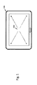
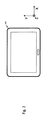
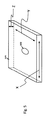
図1乃至図5は、典型的なタブレット装置への適用例を示す。本発明に係る解決手段は、電話やultrabook(登録商標)のようなモバイル装置に装備される。これらの特定の適用例のほかに、その他任意の適用(アプリケーション)、特に静電容量式タッチセンサに適用可能である。静電容量式タッチパネル104は、指103の位置をも検出するので、非常に有益である。図1に示すように、圧力センサ102が装置101の内部に埋め込まれる(組み込まれる)。この圧力センサ手段102の配置はスクリーン105の中央であることが好ましいが、該圧力センサ手段102を該中央から離れて配置することも可能である。また、複数の圧力センサ手段102を用いることも可能である。非常に好ましいのは、複数の圧力センサ手段、特に、装置101のバッテリ107内に組み込まれた複数の圧力センサ手段である(図4を参照)。
1 to 5 show an application example to a typical tablet device. The solution according to the present invention is installed in a mobile device such as a telephone or an ultrabook (registered trademark). In addition to these specific application examples, the present invention can be applied to any other application (application), in particular, a capacitive touch sensor. Since the
本発明は、好ましくは圧力検知方法に関し、特に静電容量式タッチスクリーン104のための圧力検知方法に関し、そこにおいて、圧力センサ手段102がバッテリ107の内部に又はバッテリ107上に好ましく配置されるものである。この圧力センサ手段102は、好ましくは薄いセンサであり、特に装置101がモバイル装置であるときは薄いセンサであることが好ましい。そのような圧力センサ手段102は、1以上のピエゾ電子センサ、及び/又は1以上の磁歪センサ、及び/又はその他の如何なる技術のセンサ、であり得る。アナログ値がMCU(マイクロ・コントローラ・ユニット)又はメインIC(集積回路)又はその他のADC(アナログ−デジタル変換器)によって好ましく読み取られ、読み取られた値がデジタル値に好ましく変換される。サンプルされ量子化された値は1次元を持つ。一例として、信号は好ましくは0V(ボルト)から15V(ボルト)まで読み込まれ、15V(ボルト)を超えるものには閾値が好ましく与えられる。例えばピエゾ式圧力センサから供給された0V乃至15Vは、MCUの内部で0乃至1000の範囲の整数値に好ましく変換される。0乃至1000はスカラー量であり、マトリックスの中央での該値は「1」の近傍(0.9乃至1等)であり、該値は隅に近づくにつれて減少してゆく。
The present invention preferably relates to a pressure sensing method, and in particular to a pressure sensing method for a
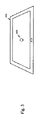
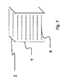
図6は、スクリーン105の側面図を示し、該スクリーン105の下側に圧力センサ手段102が配置されている。この圧力センサ手段102は、様々な圧力レベルをそれが押された位置に従って測定するものであり、好ましくは図7に示されるように正確な値を測定するために3D(三次元)マトリクスが設けられる。この3Dマトリクスは圧力センサ手段102の読み取り値を補償するために使用される。ディスプレイのスクリーン105が全方向に関して機械的に均質ではないので、X−Y軸の値のみを使用することは測定値の修正に十分ではない。Z軸の値は複数の光学的構成部材による影響を補償するために使用される。X−Y−Z座標の2D(2次元)面部分は、X−Y座標である。このX−Yマトリクスは、設計段階において、ヒューリステックに(実験的に)又はシミュレーションで若しくは両者の組合せにより作成される。可能な方法(これに限らないが)は、振動試料ふるい(vibrating sample screen)であり、及び/又はレーザ振動計(又は加速度計)で変位を測定し、及び/又は修正乗数を得ることである。Zは複数の垂直修正値を表し、特に、LCD(液晶ディスプレイ)セル、光学フィルム108、及び/又はLGP(導光板)/LGF(導光フィルム)(もしLCDスクリーンが使用されるならば)など各種構成部材の特性をそれぞれ表し、そして、それらは異なる曲げ剛性を持つ。複数の係数を決定するために、ヒューリステックに(実験的に)又はシミュレーションで若しくは両者の組合せのいずれかが再度使用される。各構成部材は個別に分析され、スクリーン105の特性はすべての構成部材の特性を加算することにより計算され得る。別の例では、スクリーン105が全体的に分析される。
FIG. 6 shows a side view of the
ただ1つの圧力センサ手段102だけを使用するならば、該圧力センサ手段102にとって最適な場所はスクリーン105の中央であろう。2以上の圧力センサ手段102が使用できるならば、該最適な場所は変更され得る。機械的な制限があるのであれば、勿論、該圧力センサ手段102は別の位置に移動することが可能である。前記3Dマトリクスは新しい位置に従って適合され得る。また、複数の圧力センサ手段102の使用が可能であり、精度が増大する。
If only one pressure sensor means 102 is used, the optimum location for the pressure sensor means 102 will be in the center of the
別の実施例において、圧力センサ手段102は、代替的に若しくは付加的に、バッテリ107の安全センサとして使用しうる。
In another embodiment, the pressure sensor means 102 may alternatively or additionally be used as a safety sensor for the
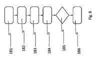
図8は、本発明の方法の好ましい処理を示す。第1のステップ182は、タッチ検出処理を示し、タッチスクリーン105上の座標が決定される。次のステップ183として、圧力センサ手段の信号が検出され、さらなるステップ184において、特に3Dマトリクスを用いて、信号レベルが正規化される。その後、ステップ185において力の大きさが判定され、ステップ186においてタッチ力(タッチ強度)が報告される。
FIG. 8 shows a preferred process of the method of the present invention. The
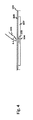
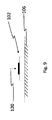
図9は、硬質要素106(特に無限質量を持つ無限硬質面)上に配置された圧力センサ手段102で圧力120を測定するための理想的な事例を示す。
FIG. 9 shows an ideal case for measuring the
図10は、現実的な事例における図9の圧力測定の適用例を示す。人の指103によって加えられる圧力120は、大部分の事例において、圧力センサ手段102の中心から離れた位置において、加えられることがこの図から理解され得る。したがって、指103がスクリーン105に接触する箇所において加えられる圧力の判定のために、検出された圧力値の修正が行われなければならない。この修正は位置対圧力関数によって行われる。
FIG. 10 shows an application example of the pressure measurement of FIG. 9 in a realistic case. It can be seen from this figure that the
参照番号122は、ユーザの手又はテーブル上部のような任意の固定された面を示し、特に硬質要素106の硬質性を増強する。この場合、硬質要素106は有限質量を持つ有限面であり、該面の硬度はLCDのk面の硬さよりもかなり高く(好ましくは数倍の硬度)、該LCDの硬度及び/又はk面の硬度は好ましくはかなり小さい(>> k LCD)。参照番号160aは、装置101の各特性、特にスクリーン、の早い段階における、時間t=0における、装置101の内部構造を示す。
図11は、図10と同様の図であるが、参照番号160bは、装置101の各特性、特にスクリーン、の遅い段階における、時間t=5年における、装置101の内部構造を示す。したがって、指103がスクリーン105に接触する箇所において加えられる圧力の判定のために、かつ、前記装置101の各特性の経年化のために、検出された圧力値の修正が行われなければならない。この修正は位置対圧力関数及び追加の経年関数によって、若しくは経年関数又は経年値を組み込んだ変形された位置対圧力関数によって、行われる。
FIG. 11 is a view similar to FIG. 10, but the
図10及び図11に関連して上述した補償及び修正が実行された後に、図12に示すような状況がその結果としてもたらされる。それはまた、有限硬質要素106から生じる影響を硬さ補償値によって補償する及び/又は修正するとも考えられる。
After the compensation and correction described above in connection with FIGS. 10 and 11, the situation as shown in FIG. 12 results. It is also conceivable to compensate and / or correct the effects arising from the finite
本発明の別の新規な特徴が図13に示されており、図13は、可屈曲性が経年(老化)により時間的に変化することを示している。もう1つの経年マトリクス又は単一の変数があり、それは経年効果を補償するために使用される時間的関数を示す。この係数もまた、ヒューリステックに(実験的に)又はシミュレーションで若しくは両者の組合せにより決められる。図示するように、経年関数は、好ましくは経年マトリクスのスカラー乗算である。経年関数は、アレニウス等式の一種、特に時間に関して指数的な及び/又は依存したもの、であり得る。 Another novel feature of the present invention is shown in FIG. 13, which shows that the bendability changes over time with age (aging). There is another aging matrix or a single variable that indicates the temporal function used to compensate for aging effects. This factor is also determined by heuristics (experimental), by simulation, or a combination of both. As shown, the aging function is preferably a scalar multiplication of an aging matrix. The aging function can be a kind of Arrhenius equation, in particular exponential and / or dependent on time.
選択されたスクリーン形式(スクリーン・オプション)に依存した、全てのこれらマトリクス及びその値は、もしスクリーン及び装置の機械的設計が別の特徴に変わったならば、変更されるものであり、そして、該スクリーン・オプションにしたがって、全てのこれらマトリクスがルックアップテーブル形式でメモリ内に記憶され得るようになっており、そのことは、より大きな製造生産性をもたらす。 All these matrices and their values, depending on the selected screen format (screen options), will be changed if the mechanical design of the screen and device has changed to another feature, and According to the screen option, all these matrices can be stored in memory in the form of a look-up table, which results in greater manufacturing productivity.
したがって、図13は、左から右に順に、マトリクス、経年修正マトリクス、経年修正済マトリクス134を示し、参照番号130は成分ごとの積を示し、参照番号132は経年関数、特に時間に依存する、を示す。図14は、バッテリ107、保護回路147、配線148、及び圧力センサ手段102を含むアセンブリグループを示す。
Accordingly, FIG. 13 shows, in order from left to right, a matrix, an aging correction matrix, an aging
バッテリ107が好ましくは2つの端子145と146を備えることがこの図から理解可能であり、第1の端子145が負極端子、第2の端子146が正極端子である。端子145と146の間には、好ましくは、ヒューズ150及び/又は保護回路147が配置される。保護回路147は、好ましくは、配線148を介して装置101のプロセッサユニット及び/又はスクリーン105に接続される若しくは接続可能である。バッテリ107は、好ましくは、多層配列からなる。1つの層が好ましくはカソード144、特にアルミニウム上のカソード、によって構成される。カソード144の上に第1のセパレータ141が配置される。第1のセパレータ141の上に、アノード142特に銅箔、が配置される。好ましくは、アノード142の上に第2のセパレータ143が配置される。圧力センサ手段102は、好ましくは、該第2のセパレータ143に接続されるか若しくはその上に配置される。第2のセパレータ143と圧力センサ手段102は、好ましくは、パウチ(袋)140特にフォイルパウチによってカバーされる。参照番号149は、バッテリ107の動作を概略的に示す。
It can be seen from this figure that the
圧力センサ手段102は、ピエゾセンサ(又はその他の圧力センサ)、特に光学的解決手段(光学的センサ)とは異なるセンサ、であり得るものであり、それ故に、表面又は平面(それは硬くて曲がらない)に固定される必要があり、そして、反対側に加えられた圧力を正しく測定し得る。LCDスクリーンは十分に硬質ではないので、また、LCD上の圧力は測定されねばならないので、圧力センサ手段102は、好ましくは、硬い有限面上に固定する必要がある。 The pressure sensor means 102 can be a piezo sensor (or other pressure sensor), in particular a sensor different from the optical solution means (optical sensor), and hence the surface or plane (it is hard and not bent). And the pressure applied to the other side can be measured correctly. Since the LCD screen is not hard enough and the pressure on the LCD must be measured, the pressure sensor means 102 should preferably be fixed on a hard finite surface.
そこで、LCDスクリーン105それ自体よりも非常に硬くかつ質量も大きい基準面が必要とされる。ユーザが装置、特に携帯電話、をその手のひらに置くとき、若しくはテーブル又はその他の堅い面上にそれを置くとき、その置かれた面が前記基準面となる。勿論、バッテリ又は背カバーは曲げられ得るが、それらはLCDよりも堅いか又は十分に堅い。
Therefore, a reference surface that is much harder and larger in mass than the
圧力センサ手段102は、バッテリ、特に、アノード−カソードとセパレータアセンブリが高い剛性を持つリチウムイオン・バッテリ、の内部に設置され得るものであり、あるいは、そのフレーム(外枠)、特に、もし利用できるならば中間フレーム(例えばマグネシウム又はアルミニウム合金からなる)の上に設置され得る。本発明の方法又は装置の配列構成は、圧力センサ手段102がバッテリパックのフレーム上又は内部に配置されるかどうかによって異なるものではない。バッテリを使用することは、製造時又は配線時に有利であり、好ましくは、中間フレームがマグネシウム及び/又はアルミニウムからなる。 The pressure sensor means 102 can be installed inside a battery, in particular a lithium ion battery in which the anode-cathode and separator assembly is highly rigid, or its frame, in particular if available. If so, it can be placed on an intermediate frame (eg made of magnesium or aluminum alloy). The arrangement of the method or apparatus of the present invention does not differ depending on whether the pressure sensor means 102 is located on or within the frame of the battery pack. The use of a battery is advantageous during manufacture or wiring, preferably the intermediate frame is made of magnesium and / or aluminum.
こうして、本発明は、装置101、特にマルチメディア装置、及び方法について述べており、そこにおいて、該装置は、スクリーン105と、プロセッサユニット152と、少なくとも1つの圧力センサ手段102とを少なくとも備え、該圧力センサ手段102はスクリーン105よりも硬い剛性要素106の上に搭載され、該圧力センサ手段102の一面側に剛性要素106が配置され、その反対面側にスクリーン105が配置され、そこにおいて、位置検出ユニットが設けられ、該位置検出ユニットは位置信号を出力するように構成され、該位置信号は、前記スクリーン105に対して圧力が加えられた位置を特定するための位置情報を提供し、前記圧力センサ手段102は圧力信号を出力するように構成され、該圧力信号は該圧力センサ手段102によって測定される前記圧力についての圧力情報を提供し、前記プロセッサユニット152は、位置対圧力関数によって前記スクリーン105に加えられた前記圧力の値を判定し、該位置対圧力関数は少なくとも前記位置情報と前記圧力情報との間の関係を規定し、前記プロセッサユニット152は前記圧力値に応じて或る機能、動作又は効果を引き起こす。
Thus, the present invention describes an
101 装置、一例としてタブレット式コンピュータ(携帯電話又はultrabook(登録商標)であり得る)
102 圧力センサ手段、特にバッテリ内部に埋め込まれている
103 圧力を加えるユーザの指
104 オンセルの静電容量式タッチパネル(インセルでも可能)
105 ディスプレイスクリーン
106 硬質面、特にバッテリの内部
107 バッテリ
108 種々の光学フィルム及び光学的構成部材
120 圧力
122 支持体、特に手又はテーブル上部
130 成分ごとの積
132 経年関数、特に時間に依存する
140 フォイルパウチ
141 第1のセパレータ
142 銅箔上のアノード
143 第2のセパレータ
144 アルミニウム上のカソード
145 負極端子
146 正極端子
147 保護回路
148 配線
149 動作
150 ヒューズ
152 プロセッサユニット
160a 早い段階における内部構造
160b 遅い段階における内部構造
181 タッチを検出する
182 タッチスクリーン上の座標を得る
183 圧力センサ信号、特にピエゾ電気電極の信号、を測定する
184 特に3Dマトリクスによって、信号レベルを正規化する
185 力の大きさを判定する
186 タッチ力を報告する
101 device, for example a tablet computer (can be a mobile phone or ultrabook®)
102 Pressure sensor means, especially 103 embedded in the
105
Claims (14)
プロセッサユニット(152)と、
少なくとも1つの圧力センサ手段(102)と
を少なくとも備える装置(101)、特にマルチメディア装置、であって、
前記圧力センサ手段(102)は剛性要素(106)上に搭載され、該剛性要素(106)は前記スクリーン(105)よりも硬く、該剛性要素(106)は前記センサ手段(102)の一面側に配置され、前記スクリーン(105)は前記センサ手段(102)の反対面側に配置され、
位置検出ユニットが設けられ、該位置検出ユニットは位置信号を出力するように構成され、該位置信号は、前記スクリーン(105)に対して圧力が加えられた位置を特定するための位置情報を提供し、
前記圧力センサ手段(102)は圧力信号を出力するように構成され、該圧力信号は該圧力センサ手段(102)によって測定された前記圧力についての圧力情報を提供し、
前記プロセッサユニット(152)は、位置対圧力関数を用いて前記スクリーン(105)に加えられた前記圧力の値を判定し、該位置対圧力関数は少なくとも前記位置情報と前記圧力情報との間の従属性を規定し、前記プロセッサユニット(152)は前記判定した圧力値に応じて或る機能、動作又は効果を引き起こす、ことを特徴とする装置。 A screen (105);
A processor unit (152);
A device (101) comprising at least one pressure sensor means (102), in particular a multimedia device,
The pressure sensor means (102) is mounted on a rigid element (106), the rigid element (106) is harder than the screen (105), and the rigid element (106) is one side of the sensor means (102). The screen (105) is arranged on the opposite side of the sensor means (102),
A position detection unit is provided, and the position detection unit is configured to output a position signal, and the position signal provides position information for specifying a position where pressure is applied to the screen (105). And
The pressure sensor means (102) is configured to output a pressure signal, the pressure signal providing pressure information about the pressure measured by the pressure sensor means (102);
The processor unit (152) determines a value of the pressure applied to the screen (105) using a position versus pressure function, the position versus pressure function being at least between the position information and the pressure information. An apparatus defining a dependency, wherein the processor unit (152) causes a function, operation or effect in response to the determined pressure value.
このデータベースは、前記プロセッサユニット(152)に接続され、
前記データベースは、前記スクリーン(105)の表面上の複数の位置についての複数の修正値Zを提供し、
前記位置対圧力関数によって、前記位置情報に応じた前記修正値Zが選択され、
前記位置対圧力関数は、該修正値で前記圧力情報を操作することによって、前記スクリーンに対して加えられた前記圧力を計算し、
若しくは、前記データベースは、前記スクリーン(105)の表面上の複数の位置についての修正関数を提供し、
前記位置対圧力関数によって、前記位置情報に応じて前記修正関数が適用され、
前記位置対圧力関数は、該修正関数で前記圧力情報を操作することによって、前記スクリーンに対して加えられた前記圧力を計算する、
ことを特徴とする請求項1の装置。 There is at least one database,
This database is connected to the processor unit (152),
The database provides a plurality of correction values Z for a plurality of positions on the surface of the screen (105);
The correction value Z corresponding to the position information is selected by the position vs. pressure function,
The position versus pressure function calculates the pressure applied to the screen by manipulating the pressure information with the correction value;
Alternatively, the database provides correction functions for a plurality of positions on the surface of the screen (105),
The correction function is applied according to the position information by the position versus pressure function;
The position versus pressure function calculates the pressure applied to the screen by manipulating the pressure information with the correction function.
The apparatus of claim 1.
前記修正値Zは、各X−Y座標における前記スクリーン(105)の複数の曲げ特性に依存するものである、ことを特徴とする請求項1又は2の装置。 The position information is defined by one position value or a plurality of position values captured for one row, where each position value is composed of an X coordinate value and a Y coordinate value,
3. Apparatus according to claim 1 or 2, characterized in that the correction value Z depends on a plurality of bending properties of the screen (105) at each XY coordinate.
前記1つの経年修正値は、少なくとも1つのスクリーン特性、特に硬さ、の変化を解消するためのパラメータを表し、
前記複数経年修正値は、異なる複数位置における、少なくとも1つのスクリーン特性、特に硬さ、の変化を解消するためのパラメータを表し、
前記経年修正関数は、前記スクリーン上の位置に応じて、少なくとも1つのスクリーン特性、特に硬さ、の変化を解消するためのパラメータを表し、
前記経年修正関数は、好ましくは、アレニウス等式又は変形されたアレニウス等式に基づく、
ことを特徴とする請求項1乃至3のいずれかの装置。 The position vs. pressure function further incorporates an aging correction value or aging correction values from an aging database or aging correction function,
The one aging correction value represents a parameter for eliminating a change in at least one screen characteristic, in particular hardness,
The multiple aging correction values represent parameters for eliminating changes in at least one screen characteristic, particularly hardness, at different multiple positions;
The aging correction function represents a parameter for eliminating a change in at least one screen characteristic, particularly hardness, depending on the position on the screen;
The aging correction function is preferably based on the Arrhenius equation or a modified Arrhenius equation,
An apparatus according to any one of claims 1 to 3, characterized in that
該バッテリは、正極端子(146)及び負極端子(145)を備え、正極端子(146)と負極端子(145)の結合を介して該装置(101)を動作するための電気エネルギーが供給される、
ことを特徴とする請求項1乃至4のいずれかの装置。 The pressure sensor means (102) is located inside the battery;
The battery includes a positive electrode terminal (146) and a negative electrode terminal (145), and is supplied with electric energy for operating the device (101) through a coupling of the positive electrode terminal (146) and the negative electrode terminal (145). ,
An apparatus according to any one of claims 1 to 4, characterized in that
前記剛性要素(106)は前記第2のセパレータ(143)によって実体化されている、
ことを特徴とする請求項5の装置。 The battery (107) includes a cathode (144) and an anode (142), the cathode (144) and the anode (142) are separated from each other by a first separator (141), and the battery (107) is connected to a pouch (140). ), And the pouch (140) is separated from the anode (142) by a second separator (143), and the pressure sensor means (102) includes the second separator (143) and the pouch (140). Placed between and
The rigid element (106) is materialized by the second separator (143);
6. The apparatus of claim 5, wherein:
ことを特徴とする請求項1乃至6のいずれかの装置。 The rigid element (106) is a part of the housing of the device (101), in particular a frame for mounting and / or stabilizing components of the device,
An apparatus according to any one of claims 1 to 6, characterized in that
該保護回路(147)は接続手段によって前記プロセッサユニット(152)及び/又はスクリーン(105)に接続され、
電力及びデータが前記保護回路(147)から前記プロセッサユニット(152)及び/又はスクリーン(105)への前記接続手段によって伝送される、
ことを特徴とする請求項5乃至7のいずれかの装置。 The negative terminal (145), the positive terminal (146) and the pressure sensor means (102) are electrically coupled to a protection circuit (147);
The protection circuit (147) is connected to the processor unit (152) and / or the screen (105) by connection means,
Power and data are transmitted by the connection means from the protection circuit (147) to the processor unit (152) and / or screen (105).
A device according to any one of claims 5 to 7, characterized in that
前記プロセッサユニット(152)は、前記圧力値及び/又は個々の動作に応じて少なくとも1つの命令及び/又は処理ルーチンを選択する、
ことを特徴とする請求項1乃至8のいずれかの装置。 An instruction database is provided, the instruction database providing instruction groups and processing routines;
The processor unit (152) selects at least one instruction and / or processing routine in response to the pressure value and / or individual actions.
An apparatus according to any one of claims 1 to 8, characterized in that
前記プロセッサユニット(152)は、前記判定した圧力値が前記危険圧力値の上である場合、安全処理、特に電力出力を減少すること、を行う、
ことを特徴とする請求項1乃至9のいずれかの装置。 A certain dangerous pressure value is pre-defined and stored in the data storage means;
The processor unit (152) performs a safety process, in particular, reduces the power output when the determined pressure value is above the dangerous pressure value.
A device according to any one of claims 1 to 9, characterized in that
前記プロセッサユニット(152)によって実行可能な全ての各動作が圧力値によって選択可能であり、
個々の動作を選択するためのすべての圧力値が所定の圧力値範囲内である、
ことを特徴とする請求項10の装置。 The dangerous pressure value is at least twice the average pressure value required to select any command and / or individual action;
All the operations that can be performed by the processor unit (152) are selectable by pressure values;
All pressure values for selecting individual actions are within a predetermined pressure value range,
The apparatus of claim 10.
前記スクリーン(105)は静電容量式スクリーン(105)であり、
該静電容量式スクリーン(105)は三次元(X,Y,Z)マトリクスを規定し、
前記位置検出ユニットは、該静電容量式スクリーン(105)の一構成部材であって、各位置のX−Y座標を検出し、
Z座標は、少なくとも1つの光学的構成部材による少なくとも1つの影響、特に、LCDセル、光学フィルム、導光板/導光フィルムのような1又は複数の前記スクリーン構成部材の曲がり、を補償するために、検出され処理される、
ことを特徴とする請求項1乃至11のいずれかの装置。 The device (101) is a multimedia device;
The screen (105) is a capacitive screen (105),
The capacitive screen (105) defines a three-dimensional (X, Y, Z) matrix;
The position detection unit is a constituent member of the capacitive screen (105), and detects XY coordinates of each position.
The Z-coordinate is to compensate for at least one influence by at least one optical component, in particular the bending of one or more said screen components such as LCD cells, optical films, light guide plates / light guide films. Detected and processed,
12. A device according to any one of the preceding claims.
前記位置検出ユニットによって位置信号を出力するステップと、ここで、該位置信号は、前記スクリーン(105)に対して圧力が加えられた位置を特定するための位置情報を提供するものであり、
前記圧力センサ手段(102)によって圧力信号を出力するステップとを備え、ここで、該圧力信号は、該圧力センサ手段(102)によって測定された前記圧力についての圧力情報を提供するものであり、
前記プロセッサユニット(152)は、位置対圧力関数を用いて前記スクリーン(105)に加えられた前記圧力の圧力値を判定し、該位置対圧力関数は少なくとも前記位置情報と前記圧力情報との間の従属性を規定し、前記プロセッサユニット(152)は前記圧力値に応じて或る機能、動作又は効果を引き起こす、
ことを特徴とする方法。 Providing a device (101) comprising a screen (105), a processor unit (152) and at least one pressure sensor means (102), wherein said pressure sensor means (102) is a rigid element (106) The rigid element (106) is harder than the screen (105), the rigid element (106) is disposed on one side of the sensor means (102), and the screen (105) Arranged on the opposite side of the means (102), provided with a position detection unit,
Outputting a position signal by the position detection unit, wherein the position signal provides position information for specifying a position where pressure is applied to the screen (105);
Outputting a pressure signal by the pressure sensor means (102), wherein the pressure signal provides pressure information about the pressure measured by the pressure sensor means (102);
The processor unit (152) determines a pressure value of the pressure applied to the screen (105) using a position vs. pressure function, and the position vs. pressure function is at least between the position information and the pressure information. The processor unit (152) triggers a function, operation or effect depending on the pressure value,
A method characterized by that.
このデータベースは、前記プロセッサユニット(152)に接続され、
前記データベースは、前記スクリーン(105)の表面上の複数の位置についての複数の修正値Zを提供し、
前記位置対圧力関数によって、前記位置情報に応じた前記修正値Zが選択され、
前記位置対圧力関数は、該修正値で前記圧力情報を操作することによって、前記スクリーンに対して加えられた前記圧力を計算し、
前記修正値Zは、該装置の各スクリーン設計に関して及び各X−Y座標に関して測定された又はシミュレートされた値に基づくものである、
ことを特徴とする請求項13の方法。 There is at least one database,
This database is connected to the processor unit (152),
The database provides a plurality of correction values Z for a plurality of positions on the surface of the screen (105);
The correction value Z corresponding to the position information is selected by the position vs. pressure function,
The position versus pressure function calculates the pressure applied to the screen by manipulating the pressure information with the correction value;
The correction value Z is based on values measured or simulated for each screen design of the device and for each XY coordinate,
14. The method of claim 13, wherein:
Applications Claiming Priority (3)
| Application Number | Priority Date | Filing Date | Title |
|---|---|---|---|
| EP15199481.1A EP3179341B1 (en) | 2015-12-11 | 2015-12-11 | Method and device for sensing pressure applied to a screen with at least one sensor means |
| EP15199481.1 | 2015-12-11 | ||
| PCT/EP2016/080394 WO2017097960A2 (en) | 2015-12-11 | 2016-12-09 | Method and device for sensing pressure applied to a screen with at least one sensor means |
Publications (2)
| Publication Number | Publication Date |
|---|---|
| JP2019504388A true JP2019504388A (en) | 2019-02-14 |
| JP2019504388A5 JP2019504388A5 (en) | 2021-05-13 |
Family
ID=55027259
Family Applications (1)
| Application Number | Title | Priority Date | Filing Date |
|---|---|---|---|
| JP2018527108A Pending JP2019504388A (en) | 2015-12-11 | 2016-12-09 | Method and apparatus for detecting pressure applied to a screen with at least one sensor means |
Country Status (7)
| Country | Link |
|---|---|
| US (1) | US11099678B2 (en) |
| EP (1) | EP3179341B1 (en) |
| JP (1) | JP2019504388A (en) |
| KR (1) | KR20180093905A (en) |
| CN (1) | CN108369467B (en) |
| TR (1) | TR201702633A2 (en) |
| WO (1) | WO2017097960A2 (en) |
Families Citing this family (4)
| Publication number | Priority date | Publication date | Assignee | Title |
|---|---|---|---|---|
| KR101910518B1 (en) * | 2017-04-11 | 2018-10-22 | 삼성전자주식회사 | Biometric sensor and device comprising the same |
| DE112018006732B4 (en) * | 2018-01-31 | 2022-03-10 | Mitsubishi Electric Corporation | TOUCH SCREEN DEVICE |
| CN109669581B (en) * | 2018-12-29 | 2021-06-15 | 联想(北京)有限公司 | Input device, input method and computing equipment |
| CN110908542A (en) * | 2019-11-29 | 2020-03-24 | 上海众链科技有限公司 | Screen assembly of intelligent terminal, screen pressure detection method and computer readable storage medium |
Citations (4)
| Publication number | Priority date | Publication date | Assignee | Title |
|---|---|---|---|---|
| JP2000231446A (en) * | 1999-02-10 | 2000-08-22 | Sharp Corp | Display integrated type tablet device and storage medium stored with automatic tablet correction program |
| JP2013127690A (en) * | 2011-12-19 | 2013-06-27 | Mitsumi Electric Co Ltd | Pressing force detection device |
| WO2015062235A1 (en) * | 2013-10-29 | 2015-05-07 | 小米科技有限责任公司 | Electronic device, battery protecting method and apparatus |
| JP2015521347A (en) * | 2012-05-14 | 2015-07-27 | ローベルト ボツシユ ゲゼルシヤフト ミツト ベシユレンクテル ハフツングRobert Bosch Gmbh | Cover film for galvanic element, electrochemical power storage device, electrochemical power storage system, flexible film for galvanic element cover, and method for calculating state parameters of electrochemical power storage device |
Family Cites Families (24)
| Publication number | Priority date | Publication date | Assignee | Title |
|---|---|---|---|---|
| WO2006013485A2 (en) * | 2004-08-02 | 2006-02-09 | Koninklijke Philips Electronics N.V. | Pressure-controlled navigating in a touch screen |
| US9182837B2 (en) * | 2005-11-28 | 2015-11-10 | Synaptics Incorporated | Methods and systems for implementing modal changes in a device in response to proximity and force indications |
| US9329719B2 (en) * | 2007-03-15 | 2016-05-03 | Apple Inc. | Hybrid force sensitive touch devices |
| US20090195959A1 (en) * | 2008-01-31 | 2009-08-06 | Research In Motion Limited | Electronic device and method for controlling same |
| US8633916B2 (en) * | 2009-12-10 | 2014-01-21 | Apple, Inc. | Touch pad with force sensors and actuator feedback |
| JP4935917B2 (en) * | 2010-03-19 | 2012-05-23 | 株式会社デンソー | Portable machine |
| WO2011156447A1 (en) * | 2010-06-11 | 2011-12-15 | 3M Innovative Properties Company | Positional touch sensor with force measurement |
| TR201009784A1 (en) * | 2010-11-26 | 2012-06-21 | Vestel Elektroni̇k Sanayi̇ Ve Ti̇caret A.Ş. | Virtual keyboard typing method. |
| EP2659337B1 (en) * | 2010-12-31 | 2021-07-28 | Nokia Technologies Oy | A display apparatus producing audio and haptic output |
| US9136509B2 (en) * | 2011-05-27 | 2015-09-15 | Apple Inc. | Battery cell with an integrated pouch metal foil terminal |
| JP5833863B2 (en) * | 2011-08-24 | 2015-12-16 | 日東電工株式会社 | Transparent conductive film and method for producing the same |
| WO2013089048A1 (en) * | 2011-12-16 | 2013-06-20 | 株式会社村田製作所 | Touch operation input device |
| JP5137150B1 (en) * | 2012-02-23 | 2013-02-06 | 株式会社ワコム | Handwritten information input device and portable electronic device provided with handwritten information input device |
| CN104335145A (en) | 2012-06-08 | 2015-02-04 | Kmt全球公司 | User interface method and apparatus based on spatial location recognition |
| US9250754B2 (en) * | 2012-09-27 | 2016-02-02 | Google Inc. | Pressure-sensitive trackpad |
| US9239627B2 (en) | 2012-11-07 | 2016-01-19 | Panasonic Intellectual Property Corporation Of America | SmartLight interaction system |
| KR102058699B1 (en) * | 2013-01-24 | 2019-12-26 | 삼성디스플레이 주식회사 | flexible display device having touch and bending sensing function |
| US9864463B2 (en) * | 2013-03-05 | 2018-01-09 | Atmel Corporation | Touch panel deformation compensation |
| US20140342193A1 (en) * | 2013-05-17 | 2014-11-20 | Tenergy Corporation | Smart battery system |
| US9182864B2 (en) | 2013-06-03 | 2015-11-10 | Rajkumari Mohindra | Pressure sensitive projected capacitive touch sensing |
| US9660301B2 (en) * | 2013-10-29 | 2017-05-23 | Xiaomi Inc. | Methods and devices for battery protection |
| US20150138112A1 (en) * | 2013-11-20 | 2015-05-21 | Nextinput, Inc. | Force sensor module for applying a preload force to a force sensor |
| US9612685B2 (en) * | 2015-04-09 | 2017-04-04 | Microsoft Technology Licensing, Llc | Force-sensitive touch sensor compensation |
| US9921679B2 (en) * | 2015-10-11 | 2018-03-20 | Pressure Profile Systems Inc. | Force-sensing touch screen input device |
-
2015
- 2015-12-11 EP EP15199481.1A patent/EP3179341B1/en active Active
-
2016
- 2016-12-09 WO PCT/EP2016/080394 patent/WO2017097960A2/en active Application Filing
- 2016-12-09 KR KR1020187015707A patent/KR20180093905A/en not_active Application Discontinuation
- 2016-12-09 JP JP2018527108A patent/JP2019504388A/en active Pending
- 2016-12-09 CN CN201680072919.9A patent/CN108369467B/en active Active
- 2016-12-09 US US15/781,904 patent/US11099678B2/en active Active
-
2017
- 2017-02-22 TR TR2017/02633A patent/TR201702633A2/en unknown
Patent Citations (4)
| Publication number | Priority date | Publication date | Assignee | Title |
|---|---|---|---|---|
| JP2000231446A (en) * | 1999-02-10 | 2000-08-22 | Sharp Corp | Display integrated type tablet device and storage medium stored with automatic tablet correction program |
| JP2013127690A (en) * | 2011-12-19 | 2013-06-27 | Mitsumi Electric Co Ltd | Pressing force detection device |
| JP2015521347A (en) * | 2012-05-14 | 2015-07-27 | ローベルト ボツシユ ゲゼルシヤフト ミツト ベシユレンクテル ハフツングRobert Bosch Gmbh | Cover film for galvanic element, electrochemical power storage device, electrochemical power storage system, flexible film for galvanic element cover, and method for calculating state parameters of electrochemical power storage device |
| WO2015062235A1 (en) * | 2013-10-29 | 2015-05-07 | 小米科技有限责任公司 | Electronic device, battery protecting method and apparatus |
Also Published As
| Publication number | Publication date |
|---|---|
| EP3179341A1 (en) | 2017-06-14 |
| CN108369467B (en) | 2021-07-13 |
| WO2017097960A3 (en) | 2017-07-13 |
| US20200333938A1 (en) | 2020-10-22 |
| CN108369467A (en) | 2018-08-03 |
| WO2017097960A2 (en) | 2017-06-15 |
| TR201702633A2 (en) | 2018-09-21 |
| EP3179341B1 (en) | 2022-07-27 |
| US11099678B2 (en) | 2021-08-24 |
| KR20180093905A (en) | 2018-08-22 |
Similar Documents
| Publication | Publication Date | Title |
|---|---|---|
| JP2019504388A (en) | Method and apparatus for detecting pressure applied to a screen with at least one sensor means | |
| EP2241960A1 (en) | Electronic device and touch screen display with force sensor | |
| JP2019049962A (en) | Portable terminal device having touch pressure sensing unit provided on side surface | |
| US20210026450A1 (en) | Portable Electronic Device Having a Haptic Device with a Moving Battery Element | |
| EP2410408B1 (en) | Portable electronic device having a waterproof keypad | |
| KR101860746B1 (en) | Rechargeable battery assembly and terminal device | |
| KR102593811B1 (en) | Structure for detecting temperature of electronic device | |
| US20120319937A1 (en) | Pressure detecting user input device | |
| KR20190082496A (en) | Method for compensating pressure value of force sensor and electronic device using the same | |
| KR20210054875A (en) | Electronic device including sensor for sensing external input | |
| EP3995938A1 (en) | Pen input device comprising battery and method for operating same | |
| KR20210073793A (en) | A electronic device with a structure for harvesting energy | |
| US10444803B2 (en) | Electronic device | |
| KR101655923B1 (en) | Sensor-actuator for touch input device and terminal using the same | |
| US10996712B2 (en) | Electronic device | |
| EP2538306A9 (en) | Pressure detecting user input device | |
| KR20190132382A (en) | Sensors, input devices and electronics | |
| CN109489798B (en) | Method and device for detecting amplitude displacement of linear motor | |
| CN205563362U (en) | Intelligent terminal | |
| CN113986042A (en) | Electronic equipment and interaction method and device thereof | |
| CA2776499C (en) | Multi-modal user input device | |
| CN110609589A (en) | Electronic device and control method thereof | |
| KR20210054149A (en) | Method for operating sensor assembly and electronic device supporting the same | |
| CN103502918B (en) | User interface element with power detection amplification | |
| KR20210012838A (en) | Electronic device and method for controlling digitizer panel of electronic device based on status of electronic pen thereof |
Legal Events
| Date | Code | Title | Description |
|---|---|---|---|
| A621 | Written request for application examination |
Free format text: JAPANESE INTERMEDIATE CODE: A621 Effective date: 20191126 |
|
| A977 | Report on retrieval |
Free format text: JAPANESE INTERMEDIATE CODE: A971007 Effective date: 20201216 |
|
| A131 | Notification of reasons for refusal |
Free format text: JAPANESE INTERMEDIATE CODE: A131 Effective date: 20201223 |
|
| A521 | Request for written amendment filed |
Free format text: JAPANESE INTERMEDIATE CODE: A523 Effective date: 20210322 |
|
| A521 | Request for written amendment filed |
Free format text: JAPANESE INTERMEDIATE CODE: A523 Effective date: 20210323 |
|
| A524 | Written submission of copy of amendment under article 19 pct |
Free format text: JAPANESE INTERMEDIATE CODE: A524 Effective date: 20210323 |
|
| A02 | Decision of refusal |
Free format text: JAPANESE INTERMEDIATE CODE: A02 Effective date: 20210420 |