JP2019503268A - Ultrasound imaging related to position - Google Patents
Ultrasound imaging related to position Download PDFInfo
- Publication number
- JP2019503268A JP2019503268A JP2018559166A JP2018559166A JP2019503268A JP 2019503268 A JP2019503268 A JP 2019503268A JP 2018559166 A JP2018559166 A JP 2018559166A JP 2018559166 A JP2018559166 A JP 2018559166A JP 2019503268 A JP2019503268 A JP 2019503268A
- Authority
- JP
- Japan
- Prior art keywords
- transducer
- scan data
- imaging device
- imaging
- scan
- Prior art date
- Legal status (The legal status is an assumption and is not a legal conclusion. Google has not performed a legal analysis and makes no representation as to the accuracy of the status listed.)
- Pending
Links
Images


Classifications
-
- A—HUMAN NECESSITIES
- A61—MEDICAL OR VETERINARY SCIENCE; HYGIENE
- A61B—DIAGNOSIS; SURGERY; IDENTIFICATION
- A61B8/00—Diagnosis using ultrasonic, sonic or infrasonic waves
- A61B8/42—Details of probe positioning or probe attachment to the patient
- A61B8/4245—Details of probe positioning or probe attachment to the patient involving determining the position of the probe, e.g. with respect to an external reference frame or to the patient
- A61B8/4254—Details of probe positioning or probe attachment to the patient involving determining the position of the probe, e.g. with respect to an external reference frame or to the patient using sensors mounted on the probe
-
- A—HUMAN NECESSITIES
- A61—MEDICAL OR VETERINARY SCIENCE; HYGIENE
- A61B—DIAGNOSIS; SURGERY; IDENTIFICATION
- A61B8/00—Diagnosis using ultrasonic, sonic or infrasonic waves
- A61B8/42—Details of probe positioning or probe attachment to the patient
- A61B8/4245—Details of probe positioning or probe attachment to the patient involving determining the position of the probe, e.g. with respect to an external reference frame or to the patient
- A61B8/4263—Details of probe positioning or probe attachment to the patient involving determining the position of the probe, e.g. with respect to an external reference frame or to the patient using sensors not mounted on the probe, e.g. mounted on an external reference frame
-
- A—HUMAN NECESSITIES
- A61—MEDICAL OR VETERINARY SCIENCE; HYGIENE
- A61B—DIAGNOSIS; SURGERY; IDENTIFICATION
- A61B8/00—Diagnosis using ultrasonic, sonic or infrasonic waves
- A61B8/44—Constructional features of the ultrasonic, sonic or infrasonic diagnostic device
- A61B8/4483—Constructional features of the ultrasonic, sonic or infrasonic diagnostic device characterised by features of the ultrasound transducer
- A61B8/4488—Constructional features of the ultrasonic, sonic or infrasonic diagnostic device characterised by features of the ultrasound transducer the transducer being a phased array
-
- A—HUMAN NECESSITIES
- A61—MEDICAL OR VETERINARY SCIENCE; HYGIENE
- A61B—DIAGNOSIS; SURGERY; IDENTIFICATION
- A61B8/00—Diagnosis using ultrasonic, sonic or infrasonic waves
- A61B8/48—Diagnostic techniques
- A61B8/483—Diagnostic techniques involving the acquisition of a 3D volume of data
-
- A—HUMAN NECESSITIES
- A61—MEDICAL OR VETERINARY SCIENCE; HYGIENE
- A61B—DIAGNOSIS; SURGERY; IDENTIFICATION
- A61B8/00—Diagnosis using ultrasonic, sonic or infrasonic waves
- A61B8/52—Devices using data or image processing specially adapted for diagnosis using ultrasonic, sonic or infrasonic waves
- A61B8/5215—Devices using data or image processing specially adapted for diagnosis using ultrasonic, sonic or infrasonic waves involving processing of medical diagnostic data
- A61B8/5238—Devices using data or image processing specially adapted for diagnosis using ultrasonic, sonic or infrasonic waves involving processing of medical diagnostic data for combining image data of patient, e.g. merging several images from different acquisition modes into one image
- A61B8/5246—Devices using data or image processing specially adapted for diagnosis using ultrasonic, sonic or infrasonic waves involving processing of medical diagnostic data for combining image data of patient, e.g. merging several images from different acquisition modes into one image combining images from the same or different imaging techniques, e.g. color Doppler and B-mode
- A61B8/5253—Devices using data or image processing specially adapted for diagnosis using ultrasonic, sonic or infrasonic waves involving processing of medical diagnostic data for combining image data of patient, e.g. merging several images from different acquisition modes into one image combining images from the same or different imaging techniques, e.g. color Doppler and B-mode combining overlapping images, e.g. spatial compounding
-
- A—HUMAN NECESSITIES
- A61—MEDICAL OR VETERINARY SCIENCE; HYGIENE
- A61B—DIAGNOSIS; SURGERY; IDENTIFICATION
- A61B8/00—Diagnosis using ultrasonic, sonic or infrasonic waves
- A61B8/56—Details of data transmission or power supply
- A61B8/565—Details of data transmission or power supply involving data transmission via a network
-
- A—HUMAN NECESSITIES
- A61—MEDICAL OR VETERINARY SCIENCE; HYGIENE
- A61B—DIAGNOSIS; SURGERY; IDENTIFICATION
- A61B8/00—Diagnosis using ultrasonic, sonic or infrasonic waves
- A61B8/58—Testing, adjusting or calibrating the diagnostic device
Abstract
撮像装置が、トランスデューサ、検出デバイスおよびプロセッサを含む。トランスデューサは、走査位置で走査されている物体の特性を検出するよう構成される放射体および受信器を含む。検出デバイスは、走査中の物体に対するトランスデューサの位置を検出するよう構成される。プロセッサは、トランスデューサが第1の位置に置かれているときに特性を表す走査情報をトランスデューサから取得することと、トランスデューサが第1の位置に置かれているときに走査中の物体に対するトランスデューサの位置を表す位置情報を検出デバイスから取得することと、当該位置情報から座標位置を決定することと、当該座標位置と当該走査情報とを関連付けることと、当該走査情報と関連付けられた当該座標位置を記憶装置に記憶させることとを行うよう構成される。The imaging device includes a transducer, a detection device, and a processor. The transducer includes a radiator and a receiver configured to detect characteristics of the object being scanned at the scanning position. The detection device is configured to detect the position of the transducer relative to the object being scanned. The processor obtains scanning information from the transducer that is characteristic when the transducer is in the first position, and the position of the transducer relative to the object being scanned when the transducer is in the first position. Is obtained from the detection device, the coordinate position is determined from the position information, the coordinate position is associated with the scanning information, and the coordinate position associated with the scanning information is stored. And storing in the apparatus.
Description
超音波撮像方法では、従来、B走査と呼ばれる直線走査を作り出すために、1列に配置された、A走査と呼ばれる点状走査の連続を使用する。A走査は、トランスデューサによる縦波またはせん断波の生成と、受信されたエコーの観察とを伴うことがある。B走査は被撮像体のスライスであり、被撮像体の当該スライスの2D画像を提供することができる。C画像と呼ばれ得る3D画像を作り出すには、一定の距離だけ離れたB走査が連続して行われる。B走査およびC走査を行うには、走査の被写体が適切な位置に(動かないよう)固定され、センサが、安定したジオメトリをもたらす直線軌道上に固定される必要がある。 The ultrasonic imaging method conventionally uses a series of dot-like scans called A-scans arranged in a row in order to create a linear scan called B-scan. The A-scan may involve the generation of longitudinal or shear waves by the transducer and observation of the received echo. The B scan is a slice of the imaging target, and can provide a 2D image of the slice of the imaging target. In order to create a 3D image, which can be referred to as a C image, B-scans separated by a certain distance are continuously performed. Performing B and C scans requires that the scanned subject be fixed in place (not to move) and the sensor be fixed on a linear trajectory that provides a stable geometry.
A走査をB走査またはC走査に変換するには、モータまたは空気圧で作動するモータ駆動の超音波プローブまたは機械的スキャナが使用され、固定軌道に沿ってプローブの動きを追跡するエンコーダも必要とされることが多い。これらの装置は、大型で、重く、高価である。故に、これらは持ち運ぶことができず、使用しにくい。走査装置のサイズおよび重量は、高感度な測定をも妨げる。代替的に、機械的な走査機構の他、フェーズドアレイトランスデューサまたは直線状トランスデューサが使用されることもあり、これらのトランスデューサは、多くの超音波トランスデューサを有する。しかしながら、このことにより走査装置のコストが増し、更には走査装置がかさばることになる。 To convert A-scan to B-scan or C-scan, motor or pneumatically driven motor-driven ultrasonic probes or mechanical scanners are used, and an encoder that tracks probe movement along a fixed trajectory is also required. Often. These devices are large, heavy and expensive. They are therefore not portable and difficult to use. The size and weight of the scanning device also hinders sensitive measurements. Alternatively, in addition to mechanical scanning mechanisms, phased array transducers or linear transducers may be used, and these transducers have many ultrasonic transducers. However, this increases the cost of the scanning device and also makes the scanning device bulky.
追加的に、被写体は使用中ずっとじっとしていなければならず、そのことが被写体に対する多大な制限となることから、被写体を固定する特別な装置が必要とされる。特別な装置で被写体を固定できない場合は、撮像が失敗するか不可能となることもある。幼児または特定の疾患を持つ人等、じっとしていることができない被写体については、走査が行われ得る前に薬の投与が行われなければならないこともある。 In addition, a special device for fixing the subject is required because the subject must remain stationary during use, which is a great limitation on the subject. If the subject cannot be fixed with a special device, imaging may fail or may not be possible. For subjects that cannot stay still, such as infants or people with certain illnesses, medication may need to be administered before scanning can be performed.
従って、より安価で、より持ち運びやすく、かつ、被写体の動きに対してより許容性のある、撮像デバイスの改善が必要である。 Therefore, there is a need for an improved imaging device that is cheaper, easier to carry, and more tolerant of subject movement.
本開示は概して、診断撮像を改善するための、位置データを関係付ける撮像デバイスに関する。 The present disclosure relates generally to imaging devices that relate position data to improve diagnostic imaging.
ある例では、撮像装置が、トランスデューサ、検出デバイスおよびプロセッサを含む。トランスデューサは、走査位置で走査されている物体の特性を検出するよう構成される放射体および受信器を含む。検出デバイスは、走査中の物体に対するトランスデューサの位置を検出するよう構成される。プロセッサは、トランスデューサが第1の位置に置かれているときに特性を表す走査情報をトランスデューサから取得することと、トランスデューサが第1の位置に置かれているときに走査中の物体に対するトランスデューサの位置を表す位置情報を検出デバイスから取得することと、当該位置情報から座標位置を決定することと、当該座標位置と当該走査情報とを関連付けることと、当該走査情報と関連付けられた当該座標位置を記憶装置に記憶させることとを行うよう構成される。 In one example, the imaging device includes a transducer, a detection device, and a processor. The transducer includes a radiator and a receiver configured to detect characteristics of the object being scanned at the scanning position. The detection device is configured to detect the position of the transducer relative to the object being scanned. The processor obtains scanning information from the transducer that is characteristic when the transducer is in the first position, and the position of the transducer relative to the object being scanned when the transducer is in the first position. Is obtained from the detection device, the coordinate position is determined from the position information, the coordinate position is associated with the scanning information, and the coordinate position associated with the scanning information is stored. And storing in the apparatus.
別の例では、撮像装置が、超音波トランスデューサ、少なくとも1つのカメラ、およびプロセッサを含む。超音波トランスデューサは、端子プローブおよびアレイプローブのうち少なくとも一方を含んでおり、体を走査するよう構成される。少なくとも1つのカメラは、トランスデューサおよび体の画像を取り込むよう構成される。プロセッサは、体に対する超音波トランスデューサの位置を決定するよう構成され、この位置とトランスデューサからの走査データとを関係付けるよう構成される。 In another example, an imaging device includes an ultrasound transducer, at least one camera, and a processor. The ultrasonic transducer includes at least one of a terminal probe and an array probe and is configured to scan the body. At least one camera is configured to capture the transducer and body images. The processor is configured to determine the position of the ultrasonic transducer relative to the body and is configured to relate this position to the scan data from the transducer.
更に別の例では、撮像方法が、超音波トランスデューサにより物体の超音波走査を行って走査データを提供する段階と、光学システムを用いて当該トランスデューサの位置を決定する段階と、当該走査データと当該トランスデューサの当該位置とを関係付ける段階と、当該走査データの2次元または3次元の表現を決定する段階と、当該トランスデューサの決定された当該位置と関連付けられる位置で、当該走査データの当該表現をディスプレイに表示する段階と、当該超音波トランスデューサを当該物体上の異なる位置まで自在に動かす段階と、当該超音波トランスデューサにより当該物体の超音波走査を行って第2の走査データを提供する段階と、当該光学システムを用いて、動かされた当該トランスデューサの位置を決定する段階と、当該第2の走査データと動かされた当該トランスデューサの当該位置とを関係付ける段階と、当該第2の走査データの2次元または3次元の表現を決定する段階と、動かされた当該トランスデューサの決定された当該位置と関連付けられる位置で、当該第2の走査データの当該表現をディスプレイに表示する段階とを含む。 In yet another example, an imaging method includes providing ultrasonic scans of an object with an ultrasonic transducer to provide scan data, determining a position of the transducer using an optical system, the scan data and the Displaying the representation of the scan data at a position associated with the position of the transducer; determining a two-dimensional or three-dimensional representation of the scan data; and a position associated with the determined position of the transducer. A step of freely moving the ultrasonic transducer to a different position on the object, a step of performing ultrasonic scanning of the object with the ultrasonic transducer and providing second scanning data, Determining the position of the moved transducer using an optical system; Associating the second scan data with the position of the moved transducer, determining a two-dimensional or three-dimensional representation of the second scan data, and determining the moved transducer Displaying the representation of the second scan data on a display at a position associated with the position.
ここで、添付図面と併せて理解される以下の説明を参照する。 Reference is now made to the following description, taken in conjunction with the accompanying drawings.
本開示に従って、撮像装置の様々な実施形態について説明する。しかしながら、本開示のデバイスおよび方法を説明するにあたっては、以下の説明が単に例示的なものに過ぎないことを理解されたい。従って、幾つかの修正形態、変更形態および代替形態が想定される。例えば、本開示では主に医療用撮像向けの超音波撮像装置について説明しているが、開示されている原理は、非超音波トランスデューサおよび非医療用撮像を含め、他の撮像デバイスに適用されてもよい。 Various embodiments of the imaging device will be described in accordance with the present disclosure. However, in describing the devices and methods of the present disclosure, it should be understood that the following description is merely exemplary. Accordingly, several modifications, changes and alternatives are envisioned. For example, although the present disclosure mainly describes an ultrasonic imaging apparatus for medical imaging, the disclosed principle is applied to other imaging devices including non-ultrasonic transducers and non-medical imaging. Also good.
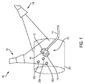
図1を参照すると、撮像装置100がトランスデューサ110を含むことができ、トランスデューサ110は、超音波トランスデューサおよびカメラ120であってよい。トランスデューサ110には、超音波トランスデューサ、電磁トランスデューサ、電磁音響トランスデューサ、渦電流式、X線式もしくは他のタイプの一端子トランスデューサ、二端子トランスデューサもしくはアレイトランスデューサ(フェーズドアレイ超音波トランスデューサが含まれるが、これに限定されることはない)のうち1または複数が含まれてよい。幾つかの実施形態では、第2のカメラ130が含まれてもよい。カメラ120およびカメラ130は、被走査体200に対して回転するそれぞれの焦点軸を有することができる。カメラの異なる焦点軸により、位置検出を改善することができるだけでなく、被走査体200のより広い視野をもたらしてより大きな走査部位を提供することもできる。曲線状物体または3次元物体における位置特定の改善には、2つのカメラが好ましい。より低い全体コストでの2次元走査には、1つのカメラが好ましいこともある。言うまでもなく、より多くのカメラが含まれてもよいことから、追加的な精度および柔軟性が撮像装置100にもたらされ得ることが理解されよう。
Referring to FIG. 1, the
トランスデューサの、変換素子114と対向する側にある面112が、特定の色またはパターン等の指標を含んで、カメラ120および/またはカメラ130によるトランスデューサ110の認識を容易にすることができる。指標は可視的であってもよいし、紫外線スペクトルまたは赤外線スペクトルの中にあってもよい。指標が紫外線スペクトルまたは赤外線スペクトルの中にある場合は、カメラ120および/またはカメラ130が紫外線発光または赤外線発光をそれぞれ検出できることが好ましい。
A
被走査体200は、1または複数のマーカ202a〜202cを含んで、カメラ120および/またはカメラ130による認識を容易にすることができる。面112および/または体200上の指標は、アクティブであってもよい。例えば、指標はLEDを含むことができ、かつ/または、カメラ120および/もしくはカメラ130により検出される可視信号、レーザ信号、赤外線信号、紫外線信号、電磁信号もしくは超音波信号を放射することができる。「カメラ」という用語は、光検出器に限定されるものではなく、トランスデューサ110および体200の相対位置を特定できる任意の適切な検出器を含んでいることが理解されよう。トランスデューサ110に赤外線LEDのような不可視光放射体を使用すると、カメラ120および/またはカメラ130の画像処理がより速くなり得る。なぜなら、指標が他の可視実在物と容易に区別されるからである。とりわけ生物医学的観点から、撮像は屋内で行われてよい。よって、不可視発光に対する太陽の干渉は著しくならないかも知れない。幾つかの例において、赤外線放射体に日光が当たる等、指標の検出が難しくなる場合は、複数のタイプの指標が提供されてよい。
The scanned
図2を参照すると、トランスデューサ110は、回路114に結合されている。回路114は、トランスデューサ110内に提供されてもよいし、ケーブル116等のケーブルを介してトランスデューサ110に結合されてもよい。高電圧パルス発生器118が高電圧パルス120を生成し、高電圧パルス120は、トランスデューサ110により体200内へ放射される。不連続点204a(例えば、密度または物質(体液か肉か骨)等の変化)に対して高電圧パルスが入射すると、反射超音波206aが発生する。その後すぐ、不連続点204bに対する高電圧パルスの入射により、反射超音波206aが発生する。高電圧パルスの送信後、送受信スイッチ122は、受信状態に切り替わる。トランスデューサは、反射超音波206aを観測した後すぐに反射超音波206bを観測し、受信された波形を、増幅器124を通してプロセッサ126に供給する。プロセッサ126は、受信された信号(例えば、受信された信号の強度および受信された信号のタイミング)に基づいて、不連続点204aおよび204bの存在を決定することができる。
Referring to FIG. 2,
プロセッサ126は、走査時にトランスデューサ110の位置に関する走査データを決定し、その情報を記憶する。撮像装置100は、カメラ120の使用により任意の特別な位置決め装置を必要とすることなく、体200上のトランスデューサ100の位置を決定することができる。カメラ120は、例えば、面112上の検出された指標の位置を記録することにより、トランスデューサ110の位置を検出することができる。画像認識技法、例えば形状検出アルゴリズムは、任意の特定の指標を必要とすることなく、トランスデューサの位置および向きを検出できることが理解されよう。面112に位置特定指標が含まれていると、計算上の複雑さが少ない位置検出が可能となり、その結果、より低コストのデバイスが実現し得る。カメラ120の位置が比較的静止した状態にあり得るので、トランスデューサ110の相対位置は、トランスデューサ110が物体200に沿って動いている間に検出されてよい。よって、カメラ120および/またはカメラ130は、走査が行われる時のトランスデューサ110の座標(例えば、x、y、z)位置と、トランスデューサ110の回転とを特定するために使用されてよい。
The processor 126 determines scan data relating to the position of the
体に置かれた較正指標202a〜202cにより、位置決定の更なる精度がもたらされ得る。なぜなら、これらの較正指標は、カメラ120の動きを相殺して、較正指標202a〜202cに対するトランスデューサ110の座標位置を決定するために使用され得るからである。指標202a〜202cは、面112のパターンとは異なる別個のパターンを有して、カメラ112によるトランスデューサの検出を容易にすることができる。
幾つかの実施形態において、トランスデューサ110は小型の場合もあり、面112はオペレータの手でカメラの視野から遮られることがある。図3を参照すると、トランスデューサ110は、カメラ120で検出可能なパターンを体200に投影するプロジェクタ118を含むことができる。パターン119は、可視光または不可視光のスペックルパターンであってよい。別の実施形態では、プロジェクタ123がスペックルパターンを投影することができ、このスペックルパターンは、トランスデューサ110で反射されるか、トランスデューサ110の影響を受ける。カメラ120により観測されるスペックルパターンの歪みは、トランスデューサ112の位置を決定するために使用されてよい。
In some embodiments, the
較正指標202a〜202cは、カメラ120(カメラ130についても同様)の位置を較正するために使用されてもよい。例えば、指標パターンが既知の寸法の外観を有しており、かつ、カメラ120が既知の焦点距離を有している場合は、カメラ120と体200との間の距離が三角法で計算されてよい。幾つかの実施形態において、較正指標は、較正(例えば、座標系のゼロ点を設定)をするために体に置かれるか付されるかした後、取り外されてよい。
較正指標202a〜202cを用いることの別の例示的な利点は、異なるタイミングで行われた走査における走査データの位置を合わせることにより、異なる時期における同じ患者の走査を比較できることである。カメラ120および/またはカメラ130からの写真資料が走査記録に含まれていると、異なる時期に撮られた走査画像を位置合わせするために較正指標202a〜202cを用いることができる。
Another exemplary advantage of using
経時的な走査の位置合わせを更に容易にすべく、較正指標202a〜202cは、注入型の物理的マーカまたは他の半永久的マーカにより提供されてよい。例えば、走査部位にUV反応型染料等の不可視インクまたは不可視染料を注入して、日常生活において別の方法では認識できないマーカを提供することができる。皮膚に小さな生体適合性マーカが挿入されてよく、そのマーカからの超音波シグネチャは、複数の超音波走査を比較する基準点としての役割を果たすことができる。幾つかの実施形態では、追加的な三角測量精度をもたらして、マーカが走査間で移動したかどうかを検出するために、複数の注入型マーカが使用されてよい。
To further facilitate scan alignment over time,
上記の通り、較正指標202a〜202c、面112の指標、光源(例えば、プロジェクタ118)は何れも必要とされないことが更に理解されよう。例えば、体200および体200に対するトランスデューサ110の位置を特定するために、他の画像処理アルゴリズムのパターン検出が使用されてよい。
It will be further understood that none of the
ある実施形態において、トランスデューサ110は、慣性測定ユニット140を含むことができ、慣性測定ユニット140は、トランスデューサ110の筐体の内部に置かれるか、筐体にしっかりと結合される。慣性測定ユニット140は、走査中にトランスデューサ110の相対移動を測定することができる。慣性測定ユニットは、3つの軸(x軸、y軸およびz軸)全てにおける相対運動と回転とを追跡し得る3軸ジャイロスコープおよび加速度計を含むことができる。撮像デバイスは、複数の慣性測定ユニットを含むこともでき、これらの慣性測定ユニットは、例えば直交し得る3つの軸上に配置される。低コストにするには、安価なデジタル慣性測定ユニットが含まれていることが好ましい。しかしながら、係る低コストのデバイスはドリフトしやすいことから、位置決めエラーの原因となり得る。図4を参照すると、カメラ120および/またはカメラ130を用いて座標系におけるトランスデューサ110の位置を検出することにより、トランスデューサ110の位置が時間t0で決定されてよい。カメラベースの位置検出の精度が高まったことから、これはゼロ位置と見なされてよい。トランスデューサ110が動かされている間、慣性測定ユニット140は、相対運動を感知して、トランスデューサ110の新しい座標位置(ひいては、走査が行われる位置)を決定するために使用されてよい。
In certain embodiments, the
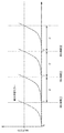
図4に示されているように、慣性測定ユニット140のドリフトエラーは、それが余りにも重大と見なされる状態に達するまで増大する。時間t1で、カメラ120および/またはカメラ130は、座標系におけるトランスデューサ110のゼロ位置をリセットするために使用されてよい。同じことが時間t2およびt3で繰り返され得ることから、カメラ120および/またはカメラ130は、所定の時間間隔で慣性測定ユニット140のドリフトエラーをなくすために使用される。
As shown in FIG. 4, the drift error of the
所定の時間間隔での再較正は、予めプログラムされた速度で行われてもよいし、慣性測定ユニット(IMU)データに基づいて予測されてもよい。例えば、IMUの動きが比較的遅い場合は、再較正がより低い速度で行われてよい。撮像デバイスの処理能力が限定され得る別の例では、走査が進行している間、より低い再較正速度が、近似画像をユーザへ表示するために使用されてよい。カメラ画像はリアルタイムまたはほぼリアルタイムで取得されてよく、かつ、ローカルに記憶されるか、記録されたIMUデータと共にクラウド記憶装置へ送信されてよい。走査後、IMU再較正速度は、撮像デバイス100自体によって、または、較正速度がより高いクラウドサーバによって再計算されてよく、より精細な超音波画像を作成するために使用される。
Recalibration at predetermined time intervals may be performed at a preprogrammed rate or may be predicted based on inertial measurement unit (IMU) data. For example, if the IMU moves relatively slowly, recalibration may occur at a lower speed. In another example where the processing capabilities of the imaging device may be limited, a lower recalibration rate may be used to display the approximate image to the user while the scan is in progress. Camera images may be acquired in real time or near real time and may be stored locally or transmitted to the cloud storage along with recorded IMU data. After scanning, the IMU recalibration rate may be recalculated by the
慣性測定ユニットが含まれている場合は、トランスデューサ110の位置決定がより素早く行われ得ることから、より速い走査が可能となる。慣性測定ユニット140は、カメラ120および/またはカメラ130を用いて位置検出の処理負担を軽減することもできる。
If an inertial measurement unit is included, faster positioning is possible because the position of the
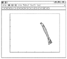
図5Aを参照すると、走査の開始時における走査データの例示的な出力プロット図が示されている。この例では、カメラ120および/またはカメラ130により、トランスデューサ110の位置がx軸上の約180mmの所、およびy軸上の225mmの所にあると決定されている。(例えば、図2に関して先ほど述べられたように)走査が行われ、トランスデューサ110の位置と対応する位置に走査データが描かれる。この時点における走査データの色は、その時点で観測された反射のタイプ、例えば反射の深度、またはその位置で検出された物質/組織タイプを表すことができる。
Referring to FIG. 5A, an exemplary output plot of scan data at the start of a scan is shown. In this example,
図5Bを参照すると、トランスデューサ110が体200全体にわたって動かされている間、走査が連続的に行われる。例えば、トランスデューサ110は、毎秒約1インチの速度で動かされてよい。オペレータは、トランスデューサを任意の方向へ自由に動かすことができ、固定軸に制約されない。追加的に、超音波プローブのより良好な位置合わせと、より繰り返し可能で正確な走査とを可能にするために、柔軟な走査ヘッドが提供されてよい。
Referring to FIG. 5B, the scanning is continuously performed while the
本開示ではオペレータまたはユーザについて述べているが、本開示に係るトランスデューサ110は、決定的な経路をたどる必要がなく、その動きの柔軟性により、オペレータなしでの撮像デバイスの使用も改善されることが理解されよう。例として、撮像デバイスは、例えばドラッグストアでのセルフサービス走査を可能にするロボットと併せて提供されてよい。
Although the present disclosure describes an operator or user, the
ロボット走査のとりわけ有用な用途の1つが皮膚科学走査である。ここでは、ロボットがトランスデューサ110を同様の位置へおおまかに位置決めすることができ、走査データと関係付けられた位置情報が、生体構造の小さな変化を検出するために経時的に記憶されてよい。
One particularly useful application for robotic scanning is dermatological scanning. Here, the robot can roughly position the
トランスデューサ110が動かされている間、カメラ120および/またはカメラ130および/または慣性測定ユニットは、座標系におけるトランスデューサの位置を追跡する。走査データは検出された位置と関係付けられ、プロット図は、体200で走査データが取得された位置における追加的な走査データを含むよう更新される。
While the
図5Cを参照すると、トランスデューサ110は、関心部位全体が走査されるまで体200に沿って動かされ続けてよい。関心部位は長方形である必要もなければ、間隔を空けたスライスの連続として方向付けされる必要もない。いかなる特定の走査領域または走査パターンに対する制約も必要とすることなく、任意の関心部位が走査されてよい。収集された走査画像は(例えば座標系を用いて)位置情報と関係付けられるものであり、画像プロセッサによりつなぎ合わされて、2次元出力または3次元出力を提供することができる。走査データは、追加的な洞察および分析をもたらすために、走査中にまたは走査後の処理で着色されてもよい。例えば、組織タイプが偽着色方式に基づいてユーザへ提示されてよい。
Referring to FIG. 5C, the
トランスデューサ110がフェーズドアレイ超音波トランスデューサを含んでいる場合は、体200の3次元走査が容易に提供され得る。なぜなら、フェーズドアレイ超音波トランスデューサは、各走査点で2次元情報を提供できるからである。2D走査画像をつなぎ合わせると、体200の3次元走査画像が提供され得る。
If the
図6を参照すると、走査データが体200の画像に重ね合わされてよく、体200の画像は、カメラ120および/またはカメラ130により容易に取得され得る。走査データは着色トレースとして提示されてよく、その色は反射の深度等、その位置で取得された走査データの情報を表す。撮像デバイス100により、重要な追加的走査データがユーザへ提供され得る。例えば、ユーザは走査位置を選択して、その位置の走査データにアクセスすることができ、この走査データは未処理の走査データを含むことができる。
With reference to FIG. 6, the scan data may be superimposed on the image of the
図6に示されている例では、位置302aおよび302bが選択されている。ディスプレイは、位置302aおよび302bとそれぞれ関連付けられた走査データ304aおよび走査データ304bを含む。この例において、走査データは、両方の位置に0〜150マイクロメートルの範囲の反射があることを示している。位置302aでは、約200〜250マイクロメートルの所に反射がある(この反射は、体200の表面下に密度が変化する物体が存在することを示し得る)。位置302bでは、約300〜350マイクロメートルの所に追加的特徴の反射がある。
In the example shown in FIG. 6,
図7を参照すると、位置と関係付けられた超音波撮像を行うプロセスが説明されている。段階S100では、超音波走査データがトランスデューサ110から取得される。段階S120では、カメラ120および/またはカメラ130からの画像データが取得される。段階S100およびS110は、任意の順序で行われてよいことが理解されよう。とりわけ後の繰り返し処理では、慣性測定ユニットを含んでいる実施形態において、画像データが慣性測定データで拡張されてもよいし、慣性測定データに置き換えられてもよいことが更に理解されよう。段階S120では、段階S100の超音波走査データが段階S110の位置データと共に処理されて、走査データと位置データとの関係付け、および、走査データと座標系との関連付けが行われる。段階S100、S110およびS120は、ユーザによりトランスデューサが動かされている間、走査が完了するまで繰り返されてよい。
Referring to FIG. 7, a process for performing ultrasound imaging associated with a position is described. In step S100, ultrasound scan data is acquired from the
段階S110のとりわけ後の繰り返し処理については、計算の必要性を減らすために予備知識が利用され得ることが理解されよう。例えば、走査は毎秒1インチといった速度で行われることが予想され得る。座標系におけるトランスデューサの以前の位置が分かっているかも知れないので、カメラ120および/またはカメラ130のカメラ感知領域は、予想されるトランスデューサ110の位置を含んでいる部位を取り囲むように減らされてよい。
It will be appreciated that prior knowledge can be utilized to reduce the need for computation, especially for the later iterations of step S110. For example, scanning can be expected to occur at a rate of 1 inch per second. Since the previous position of the transducer in the coordinate system may be known, the camera sensing area of
3次元感知については、複数のカメラが関与するので光追跡がますます遅くなり得る。座標系におけるトランスデューサ110の位置の決定は、複数のカメラ間での視差マップの計算を含むことができる。この視差マップに基づいて、追跡されたトランスデューサ110の3次元位置が推定されてよい。視差マップは、かなりのコンピューティング資源およびパターンマッチングを伴うことがあり、カメラ感知領域が減少すると、より速い位置分解能が得られることがある。慣性測定ユニット140が含まれている例では、カメラ感知領域を減らすと較正速度(例えば、時間間隔t1−t0等)が増すこともあり、この較正速度で慣性測定ユニットのドリフトエラーがリセットされることによって、分解能が高まり得る。
For 3D sensing, light tracking can become increasingly slower due to the involvement of multiple cameras. Determining the position of the
走査後(または走査中)、段階S130では、位置と関係付けられた走査データがつなぎ合わされて、超音波走査の3D表現を提供することができる。段階S140では、関係付けられた走査データが分析され、例えば深度測定値および密度測定値に基づいて、走査データの特性が決定され得る。係る特性は、既知のデータから血液、骨、脂肪、臓器等を特定することを含むことができる。 After scanning (or during scanning), in step S130, the scan data associated with the position can be stitched together to provide a 3D representation of the ultrasound scan. In step S140, the associated scan data can be analyzed and the characteristics of the scan data can be determined based on, for example, depth measurements and density measurements. Such characteristics can include identifying blood, bone, fat, organs, etc. from known data.
走査領域に関する背景情報、並びに/または、カメラ120および/もしくはカメラ130からの画像認識は、組織タイプを特定する環境を提供するために使用されてよい。例えば、腕が走査されている場合は、一定の深度に骨の部位を含んでいる薄い肉質の部位があることが予想され得る。腕が走査されていることをユーザが指定してもよいし、腕が走査されていることをカメラ120および/またはカメラ130が画像認識により決定してもよい。別の例として、腹部が走査されている場合は、一定の深度に臓器部位を含んでいる脂肪組織があることが予想され得る。ここでも、腹部が走査されていることをユーザが指定してもよいし、腹部が走査されていることをカメラ120および/またはカメラ130が決定してもよい。
Background information regarding the scan area and / or image recognition from the
カメラ120および/または130での検出により、(部位が分かっていない場合と比較して)より正確な結果、更には、より良好なユーザ体験が容易になり得る。なぜなら、走査が行われ得る前にユーザに要求される情報およびセットアップ段階が少なくなるからである。カメラベースの撮像と超音波撮像とを組み合わせることの例示的な他の利点は、検査中の身体部位に基づいて、トランスデューサ110のビーム形成パラメータが選択され得ること、例えば自動的に最適化され得ることである。
Detection with
例えば、より厚い脂肪層を有する身体部位については、より高い励起電圧が使用されてよい。トランスデューサ110は、複数の周波数を送信することが可能であってよく、アレイプローブ等、幾つかの場合には、複数の周波数を同時に送信することが可能であってよい。検査中の身体部位の決定(またはユーザからの他の入力)に基づいて、超音波走査周波数は選択されてよく、それらの走査周波数と関連付けられたそれらのトランスデューサ要素のパルスがオンにされてよい。更に、特定の病変の撮像と関連する深度に基づいて、低雑音増幅器(例えば増幅器124)の時間利得制御は変更されてよい。
For example, for body parts having a thicker fat layer, a higher excitation voltage may be used. The
トランスデューサ110は、ダイナミックレンジを提供するために、アナログデジタル変換器(ADC)のフロントエンドを使用することができる。増幅器の利得は、受信された信号をADCにより処理され得る範囲内で維持するよう、動作中、動的に調節されてよい。この利得は、増幅器(例えば増幅器124)により受信されたアナログエコーに応答して、かつ/または、被写体に関する履歴情報に応答して、自動的に制御されてよい。高い振幅反射がある場合は、走査の前半で利得が減らされてよく、より低い振幅反射がある場合は、走査の後半で利得が増やされてよい。時間ベースの利得制御は、システム雑音全体を減らすために、走査の後半で起きる後の反射を活用することができる。感知深度範囲に合わせてシステムを更に調整するために、深度感知制御が使用されてよく、深度感知制御は、時間に基づいて利得をモデル化することができる。場合によっては、感知深度に基づいて必要とはされない受信器のスイッチが、完全に切られてもよい。
The
自動利得制御曲線は、例えば被走査病変および既往歴に応じて、動作中、患者毎に調節されてよい。例えば、患者が一定量の体脂肪または骨密度を有する場合は、利得曲線を調整しながらそのことが考慮されてよい。超音波、X線、MRI等の複数の撮像技法により得られる長期的なデータが、利得曲線を決定するために組み合わされてよい。 The automatic gain control curve may be adjusted for each patient during operation, for example, depending on the scanned lesion and history. For example, if a patient has a certain amount of body fat or bone density, this may be taken into account while adjusting the gain curve. Long-term data obtained by multiple imaging techniques such as ultrasound, X-ray, MRI, etc. may be combined to determine the gain curve.
腹部等の幾つかの身体部位については、同時にまたは順々に励振される複数の周波数を選択するのが望ましいこともある。トランスデューサ110が多様式(多周波)の直線状マルチ送受信デバイスアレイを含んでいる場合は、各アレイが、異なる周波数で動作する複数の送受信デバイスを備えることができる。各周波数が特定の走査深度に合わせて選択されてよい。アレイの送受信デバイスは、特定の位置に関する走査深度の必要性に応じて、スイッチを入れられたり切られたりしてよい。スイッチが切られた送信器は、受信器のうち幾つかを無視すること、および、トランスデューサ110から来るデータストリーム内のデータ量を減らすことにより、全体の雑音を減らすことができる。所望の物理的被覆領域に応じて、複数のアレイがトランスデューサ110に使用されてよい。トランスデューサ110に複数のアレイを使用すると、走査速度が高まり得る。これらのアレイは、物理的にまとめて走査されることから、人工知能パターン認識等の技法を用いて組み合わされてもよく、最高の精度が得られるよう非常に近い位置合わせで組み合わされてよい。
For some body parts, such as the abdomen, it may be desirable to select multiple frequencies that are excited simultaneously or sequentially. If the
信号処理は、走査部位に基づいて選択されてもよい。例えば、異なる信号処理アルゴリズムが、心臓の走査および胎児の走査に使用されてよい。 The signal processing may be selected based on the scanning site. For example, different signal processing algorithms may be used for cardiac scanning and fetal scanning.
被写体のパラメータおよび履歴と被写体の以前の走査とが考慮される場合は、撮像が更に改善し得る。例えば、まずは、カメラを用いて体脂肪の増加または減少が推定されてよい。カメラ120および/またはカメラ130により取得される現在の画像を用いて患者の以前の画像を分析することにより被写体の変化を検出することに応答して、超音波ビーム形成パラメータおよび信号処理アルゴリズムは、被写体の体脂肪変化に基づいて微調整されてよい。
Imaging can be further improved if subject parameters and history and previous scans of the subject are considered. For example, first, an increase or decrease in body fat may be estimated using a camera. In response to detecting subject changes by analyzing previous images of the patient using current images acquired by
走査プロセスにおける例示的な利点の別の例、すなわち所望の走査経路が、カメラ120および/またはカメラ130および/または較正指標202a〜202cにより被写体の3Dモデル等のモデルに基づいて決定されてよく、較正指標202a〜202cは、注入型バイオマーカであってよい。被走査領域は、自動的にまたはユーザにより決定されてよい。次いで、プロジェクタ123等のプロジェクタが、被走査部位を体200に投影することができ、プロジェクタは、レーザプロジェクタ、光学プロジェクタ、ホログラフィックプロジェクタまたは他のタイプのプロジェクタであってよい。幾つかの実施形態では、走査が行われている間、十分に走査され、かつ、十分な相関走査データの記憶された部位が、体200の、プロジェクタ123により照射または特定される部分から排除されてよい。このように、ユーザは、全ての位置が走査されてもはや表示されなくなるまで、表示された位置において体を走査しさえすればよい。
Another example of exemplary benefits in the scanning process, i.e., the desired scanning path, may be determined based on a model, such as a 3D model of an object, by
言うまでもなく、記載の段階の順序は変更されてよく、記載の光学検出技法および調節技法の幾つかまたは全てが、段階S100、S110、S120およびS130において、またはこれらの段階の前に行われてよいことが理解されよう。 Of course, the order of the described steps may be changed, and some or all of the described optical detection and adjustment techniques may be performed at or prior to steps S100, S110, S120 and S130. It will be understood.
段階S150において、3次元表現は着色されてよい。例として、例えば、骨は白く、血液は赤い等といった、偽着色技法が使用されてよい。段階S160において、A走査(例えば、点状走査)情報は、予想外の反射といった異常がないか走査されてよい。係る異常は何れも、ディスプレイ上で強調表示されてユーザの注意を促すことができる。 In step S150, the three-dimensional representation may be colored. By way of example, false coloring techniques may be used, for example, bones are white, blood is red, etc. In step S160, the A-scan (eg, dot scan) information may be scanned for abnormalities such as unexpected reflections. Any such anomalies can be highlighted on the display to alert the user.
幾つかの実施形態では、同じ患者の以前の走査データが、現在の走査データと比較されてよい。位置と関係付けられた走査データにより、異なる走査時期の走査データは、区別ができるよう位置合わせされて容易に比較されることが可能となる。 In some embodiments, previous scan data for the same patient may be compared to current scan data. The scan data associated with the position allows scan data at different scan times to be aligned and easily compared so that they can be distinguished.
段階S180において、走査データは診断に利用されてよい。 In step S180, the scan data may be used for diagnosis.
記載の撮像システムは、従来のシステムに勝る非限定的な利点を多く提供する。例えば、B走査をC走査に変換されるよう適切に位置合わせするのに煩雑な装置が必要とされることなく、2D走査および3D走査が作り出され得る。記載の撮像システムにより、動きの制約を受けることなく物体の部位を走査する自由が追加的にユーザへ与えられる。 The described imaging system offers many non-limiting advantages over conventional systems. For example, 2D and 3D scans can be created without the need for cumbersome equipment to properly align B scans to be converted to C scans. The described imaging system additionally gives the user the freedom to scan the part of the object without being restricted by movement.
位置と関係付けられた走査データの追加的利点としては、より大きな分解能が提供され得ることだけでなく、走査データが、従来の処理手法では失われる追加的情報を含み、更には、異なる時期の走査を関係付けて物体状況の微少変化に関する分析を可能とすることも挙げられる。生物医学的観点から、これらの微少変化は、疾患の早期検出上、重要であり得る。あらゆる人にとって正常範囲内にあり得ることが、特定の人にとっては重大な変化であり得る。 Additional benefits of scan data associated with position include not only that greater resolution can be provided, but also that the scan data contains additional information that is lost in conventional processing techniques, and at different times. It is also possible to relate scans to enable analysis of minute changes in object status. From a biomedical point of view, these minor changes can be important for early detection of disease. Being within the normal range for everyone can be a significant change for a particular person.
撮像デバイスは、被写体毎に個々のバイオメトリクスに基づいて、生物学的位置システムを提供することができる。走査データと関連付けられた相関位置情報は、非常に正確であり得る。このことにより、同じ位置における複数の走査の時刻歴を比較するだけでなく、年齢、性別、民族性等といった患者情報を考慮しながら非常に大きな走査データベースを用いて走査を比較することも可能となる。 The imaging device can provide a biological location system based on individual biometrics for each subject. The correlated position information associated with the scan data can be very accurate. This makes it possible not only to compare the time histories of multiple scans at the same position, but also to compare scans using a very large scan database while taking into account patient information such as age, gender, ethnicity, etc. Become.
カメラ120および/またはカメラ130からの入力に基づいて、撮像デバイスは、走査中の病変を特定することができ、これをその特定の位置において(例えば、既知のデータベースまたは履歴データベースからの)超音波シグネチャと比較することができる。この比較に基づいて、異常な病変が検出され得る。言うまでもなく、この利点は、生物医学的な撮像領域に限定されるものではなく、工業用撮像、例えば、航空機部品の点検といった他の領域にも適用可能である。
Based on input from the
特定の位置でありながらも異なる時期の超音波走査を比較することにより、検出漏れをなくすことができる。例えば、超音波およびX線(マンモグラフィ)に基づく乳癌のスクリーニングでは多数の検出漏れがある。しかしながら、同じ位置における数週間以内の連続的な超音波走査が比較される場合は、疑わしい乳癌の潜在的な増殖が観測され得る。本明細書で説明されている正確な位置追跡システムを用いると、人間の目では認識できない非常に微細な腫瘍の増殖を観測することが可能となり得る。加えて、検出漏れを更に減らすには、未処理の走査データ(例えば、A走査データ)が多くの位置から互いに比較されてよく、検出漏れを更になくすためには、パターンマッチング/機械学習アルゴリズムが利用されてよい。 A detection omission can be eliminated by comparing ultrasonic scans at different times even at a specific position. For example, screening for breast cancer based on ultrasound and X-rays (mammography) has numerous detection omissions. However, if sequential ultrasound scans within a few weeks at the same location are compared, suspicious potential growth of breast cancer can be observed. With the accurate location tracking system described herein, it may be possible to observe very fine tumor growth that cannot be recognized by the human eye. In addition, to further reduce detection omissions, unprocessed scan data (eg, A scan data) may be compared to each other from many locations, and pattern matching / machine learning algorithms may be used to further eliminate detection omissions. May be used.
記載の撮像デバイスは、皮膚科学的な撮像にとりわけ有用であり得る。第1の段階では、カメラ120および/またはカメラ130から得られた被写体の視覚画像が互いに比較されて、疑わしい癌領域が特定されてよい。第2の段階では、疑わしい位置において超音波走査が行われてよい。組み合わされた光超音波走査の1セッション、または複数の係る走査の時刻歴の比較に基づいて、皮膚癌が悪性になる前に検出され得る。
The described imaging device may be particularly useful for dermatological imaging. In the first stage, visual images of the subject obtained from
別の例としては、従来の撮像技法が、結果として得られる処理画像に重点を置いたものとなっている。A走査データおよびB走査データは処理されて、C走査が提供される。C走査は更に処理されて、人間の読み取れる画像が提供される。ユーザ、例えば放射線科医は、人間が読み取れる画像のむらを見つけようと試みて、その画像のパターン認識分析を実行しようと試みることができる。 As another example, conventional imaging techniques focus on the resulting processed image. The A scan data and B scan data are processed to provide a C scan. The C scan is further processed to provide a human readable image. A user, for example, a radiologist, can attempt to find non-uniformity in an image that can be read by a human and attempt to perform pattern recognition analysis on the image.
しかしながら、係る分析およびパターン認識は、既に大量に処理されたデータに基づいているので、不正確さおよび誤検出をもたらす。対照的に、記載の撮像システムは、走査データに関連付けられた位置/座標情報と共に実際の走査データ(例えば、A走査データまたはB走査データ)を記憶する。走査データは、人間が読み取れる画像よりもはるかに多くの情報を含む。例えば、走査データは、その位置で測定された全ての密度音響インピーダンス情報および反射を含んでいる時間/振幅トレースの全体を含むことができる。より正確な結果およびより少ない誤検出をもたらすために、未処理の走査データ自体(例えば、密度音響インピーダンス情報)に対して分析およびパターン認識が行われてよい。 However, such analysis and pattern recognition results in inaccuracies and false detections because it is based on already processed data. In contrast, the described imaging system stores actual scan data (eg, A scan data or B scan data) along with position / coordinate information associated with the scan data. Scan data contains much more information than a human readable image. For example, the scan data can include the entire time / amplitude trace including all density acoustic impedance information and reflections measured at that location. Analysis and pattern recognition may be performed on the raw scan data itself (eg, density acoustic impedance information) to provide more accurate results and fewer false detections.
図8を参照しながら、人工知能(AI)支援診断の例について説明する。A走査データ等の走査データ402は、メタデータ404と関連付けられてトレーニングデータベース410に記憶されてよい。メタデータ404は、走査データ402に関する位置相関等の情報と、走査データ402の被写体に関するバイオメトリック情報と、診断情報とを含むことができる。走査が別の被写体で行われる場合は、AIエンジン420が、A走査データ等の走査データ422とメタデータ424とを含むことができ、メタデータ424は、走査データ422に関する位置相関等の情報と走査データ422の被写体に関するバイオメトリック情報とを含むことができる。AIエンジン420は、トレーニングデータベースを参照して、例えば人工知能検索アルゴリズムにより、走査データ自体に基づく検索を実行する。AIエンジンは、出力として、示唆される診断430を提供することができる。
An example of artificial intelligence (AI) support diagnosis will be described with reference to FIG.
更には、トランスデューサが動きの制約を受けず、かつ、位置情報がx、y、z軸情報およびトランスデューサ回転情報の両方を含み得ることから、時系列の走査データは重複し得る。それは、ユーザが同じ部位を2回以上通ったからだけでなく、物体表面の輪郭により深さ方向の走査の軌跡が重複するからでもある。記載の撮像システムは、交差および重複しているこのデータの利点を生かして、結果として得られる、はるかにより細かい分解能の走査データを提供することで精度を更に高めることができる。 Furthermore, since the transducer is not constrained and the position information can include both x, y, z-axis information and transducer rotation information, time series scan data can overlap. This is not only because the user has passed the same part twice or more, but also because the scanning trajectories in the depth direction overlap due to the contour of the object surface. The described imaging system can take advantage of this data to intersect and overlap to further improve accuracy by providing the resulting much finer resolution scan data.
図9を参照しながら、例示的な撮像デバイスの例示的なハードウェア概略図について説明する。 With reference to FIG. 9, an exemplary hardware schematic of an exemplary imaging device will be described.
撮像デバイスは、処理ユニット502、メモリユニット504、入出力ユニット506および通信ユニット508を含むことができる。処理ユニット502、メモリユニット504、I/Oユニット506および通信ユニット508の各々は、本明細書で説明されている撮像デバイスと関連付けられる動作を行うためのサブユニットを1または複数含むことができ、汎用ハードウェア、特定用途向けハードウェアおよび/またはソフトウェアを含むことができる。
The imaging device can include a
処理ユニット502は、メモリユニット504、I/Oユニット506および通信ユニット508のうち1または複数だけでなく、含まれている任意のサブユニット、要素、コンポーネント、デバイスおよび/または機能も制御することができる。追加的に、1つの処理ユニット502が示され得る一方で、複数の処理ユニットが存在してよく、かつ/または含まれてよい。よって、処理ユニット502(および/または、処理ユニット502の様々なサブユニット)により実行されている通りに命令が説明され得る一方で、これらの命令は、1または複数のデバイスにおいて、同時に、順次に、かつ/または、1もしくは複数の処理ユニット502により実行されてよい。
The
処理ユニット502は、1または複数のコンピュータ処理ユニット(CPU)チップおよび/またはグラフィック処理ユニット(GPU)チップとして実装されてよく、コンピュータ命令を実行し得るハードウェアデバイスを含むことができる。本明細書で説明されている画像処理技法としてGPUを使用すると、とりわけ、撮像データを分析して、トランスデューサの位置を検出し、かつ、座標系におけるトランスデューサの位置を空間的に捉えるという観点から、処理時間および精度上の利点がもたらされ得る。
The
処理ユニット502は、命令、コード、コンピュータプログラムおよび/またはスクリプトを実行することができる。これらの命令、コード、コンピュータプログラムおよび/またはスクリプトは、メモリユニット504、I/Oユニット506、通信ユニット508から受信されてよく、かつ/または、これらのユニットに記憶されてよい。
The
幾つかの実施形態において、処理ユニット502は、数ある要素の中でもとりわけ、データ取得・信号処理ユニット520、画像/グラフィック処理ユニット522、空間相関ユニット524および慣性処理ユニット526等のサブユニットを含むことができる。処理ユニット502の上記サブユニットの各々は、通信可能にかつ/または動作可能に互いと結合されてよい。
In some embodiments, the
データ取得・信号処理ユニット520は、トランスデューサ110により受信される信号の分析と走査データの処理とを容易にすることができる。画像/グラフィック処理ユニットは、カメラ120および/またはカメラ130からの画像データの分析を容易にすることができる。空間相関ユニット524は、走査データと位置データとの相関を容易にすることができる。慣性処理ユニット526は、慣性測定ユニット140からのデータの処理を容易にすることができる。AIエンジン526aは、図8を参照して述べられているAIエンジン420の処理を容易にすることができる。
Data acquisition and
幾つかの実施形態において、メモリユニット504は、動作中に様々なファイルおよび/もしくは情報を記憶、リコール、受信、送信するため、かつ/または、それらへアクセスするために利用されてよい。例えば、メモリユニット504は、走査データ、位置データおよび以前の走査データを、例えば、同じ被写体または他の同様の被写体に関する以前の位置と関係付けられた走査データと共に、記憶、リコールおよび/または更新するために利用されてよい。メモリユニット504は、固体記憶媒体、ハードディスク記憶媒体および/または仮想記憶媒体等といった様々なタイプのデータ記憶媒体を含むことができる。メモリユニット504は、ハードドライブおよび/またはサーバ等の専用ハードウェア要素だけでなく、クラウドベースの記憶ドライブ等のソフトウェア要素も含むことができる。
In some embodiments, the
本明細書で説明されているメモリユニット504、および/またはそのサブユニットの何れかは、ランダムアクセスメモリ(RAM)、リードオンリメモリ(ROM)および/または様々な形の二次記憶装置を含むことができる。RAMおよび/または不揮発性記憶装置は、揮発性データを記憶するため、かつ/または、処理ユニット502により実行され得る命令を記憶するために使用されてよい。
I/Oユニット506は、本明細書で説明されている撮像動作を行うのに有用な情報を受信、送信および/または提示するためのハードウェア要素および/またはソフトウェア要素を含むことができる。例えば、I/Oユニット506の要素は、ユーザデバイスを介してユーザからユーザ入力を受信するため、画像を取り込むため、かつ/または、情報をユーザへ表示するため等に使用されてよい。このようにして、I/Oユニット506は、人間(または人間以外)のユーザとインタフェースで接続することができる。本明細書で説明されているように、I/Oユニット506は、トランスデューサ制御ユニット560、検出器制御ユニット562および表示制御ユニット564等のサブユニットを含むことができる。
The I /
トランスデューサ制御ユニットは、トランスデューサ110の動作を制御することができる。例えば、トランスデューサ制御ユニットは、高電圧パルス発生器118およびT/Rスイッチ122を制御することができる。検出器制御ユニット562は、カメラ120および/またはカメラ130を制御することができる。表示制御ユニットは、ユーザディスプレイを制御して、例えば図5A〜図5Cおよび図6に示されている出力を生成することができる。
The transducer control unit can control the operation of the
I/Oユニット506は、本明細書で説明されている、実行されたプロセスの結果として、情報の受信、送信、処理、提示、表示、入力および/または出力を容易にすることができる。幾つかの実施形態において、I/Oユニット506は、ユーザデバイス、コンピューティングシステム、サーバ、ハンドヘルド型コンピューティングデバイスおよび/または同様のデバイスの1または複数の要素を含むことができる。故に、I/Oユニット506は、ユーザがインタフェースで接続する様々な要素を含むことができ、ユーザからの入力を受信および/または収集し、走査を実行し、走査中にスキャナの位置を検出するためのキーボード、タッチスクリーン、ボタン、センサ、バイオメトリックスキャナ、レーザ、マイク、カメラおよび/または別の要素を含むことができる。追加的かつ/または代替的に、I/Oユニット506は、ユーザに対するデータの提示および/もしくは出力のため、または、カメラ120および/もしくはカメラ130による観測のためのディスプレイ、スクリーン、センサ、振動機構、発光ダイオード(LED)、スピーカー、無線自動識別(RFID)スキャナおよび/または別の要素を含むことができる。
The I /
通信ユニット508は、他のコンピューティング環境および/または第三者サーバシステム等との通信の確立、維持、監視および/または終了を容易にすることができる。通信ユニット508は、様々な要素(例えば、ユニットおよび/またはサブユニット)間の通信を容易にすることもできる。通信ユニット508は、ハードウェア要素および/またはソフトウェア要素を含むことができる。例えば、通信ユニット508は、特定のネットワークおよび/またはネットワークタイプにより必要とされる通信プロトコルを検出かつ/または定義することができる。通信ユニット508により利用される通信プロトコルには、Wi−Fiプロトコル、Li−Fiプロトコル、セルラデータ・ネットワーク・プロトコル、Bluetooth(登録商標)プロトコル、WiMAX(登録商標)プロトコル、Ethernet(登録商標)プロトコルおよび/または電力線搬送通信(PLC)プロトコル等が含まれてよい。
The
ある例において、通信ユニット508は、ネットワーク510を通してサーバ512と通信することができる。このことは、より小型でより安価な撮像デバイスにとって好都合であり得る。なぜなら、計算上複雑な機能がクラウドベースのサービス等のサービスにオフロードされ得るからである。例えば、図8の観点から述べられる位置と関係付けられた走査データ(例えば、未処理の走査データ)を比較するためのAI方式の画像認識は、サーバ512のAIエンジン528により行われてよい。その決定の結果は、ネットワーク510および通信ユニット508を介して撮像デバイスに戻されてよい。AI方式の画像認識は計算上複雑となり得ることから、AIパターン認識を撮像デバイス自体に実装するコストが、または、典型的なサーバに実装するコストですら高くなり得る。それでもなお、大量の走査データを用いたコスト効果分析が、サービスまたはクラウドコンピューティングモデルにソフトウェアを用いて実現され得る。サービスプロバイダが、高性能コンピューティングシステムで計算を行うことに対して課す料金はわずかであってよく、高性能コンピューティングシステムは、撮像デバイスにより行われ得る時間のごく一部の時間で分析を実行することができる。次いで、その結果は(例えば、表示制御ユニット564を介して)、ユーザに表示して、被写体の記録と共に(例えば、メモリユニット504、または、撮像デバイスもしくはネットワーク上の他の記憶装置に)記録するために、撮像デバイスへ素早く戻され得る。
In certain examples, the
上記の製品、システムおよび方法により多大な利点がもたらされ得ることが理解されよう。例えば、ハードウェアのコストが劇的に減少するだけでなく、コストの減少、並びに、診断の質および有効性の向上も実現し得る。このことにより、特に良質の医療がこれまでなかった環境において、多くの人々の予後の著しい改善がもたらされ得る。 It will be appreciated that the above products, systems and methods can provide significant advantages. For example, not only can the cost of hardware be dramatically reduced, but also a reduction in cost and improved diagnostic quality and effectiveness. This can lead to a significant improvement in the prognosis of many people, especially in environments where there has never been a good quality of care.
以上、開示されている原理に係る様々な実施形態が説明されてきたが、これらは単なる例として提示されたものであり、限定するものではないことを理解されたい。例えば、本開示は、超音波撮像または医療用撮像に限定されるものではない。 While various embodiments of the disclosed principles have been described above, it should be understood that these have been presented by way of example only and not limitation. For example, the present disclosure is not limited to ultrasound imaging or medical imaging.
よって、本発明の広がりおよび範囲は、上記の例示的な実施形態の何れによっても限定されるべきではないが、請求項および本開示からもたらされるそれらの均等物に従ってのみ定義されるべきである。更には、記載の実施形態において上記の利点および特徴が提供されているが、もたらされた係る請求項の用途は、上記の利点の何れかまたは全てを達成するプロセスおよび構造に限定されないものとする。 Thus, the breadth and scope of the present invention should not be limited by any of the above-described exemplary embodiments, but should be defined only in accordance with the claims and their equivalents resulting from this disclosure. Furthermore, while the advantages and features described above are provided in the described embodiments, the use of such claims as derived is not limited to processes and structures that achieve any or all of the advantages described above. To do.
Claims (25)
走査中の前記物体に対する前記トランスデューサの位置を検出するよう構成される検出デバイスと、
プロセッサと
を備える撮像装置であって、前記プロセッサは、
前記トランスデューサが第1の位置に置かれているときに、前記特性を表す走査情報を前記トランスデューサから取得することと、
前記トランスデューサが前記第1の位置に置かれているときに、走査中の前記物体に対する前記トランスデューサの前記位置を表す位置情報を前記検出デバイスから取得することと、
前記位置情報から座標位置を決定することと、
前記座標位置と前記走査情報とを関連付けることと、
前記走査情報と関連付けられた前記座標位置を記憶装置に記憶させることと
を行うよう構成される、撮像装置。 A transducer having a radiator and a receiver configured to detect characteristics of an object being scanned at a scanning position;
A detection device configured to detect a position of the transducer relative to the object being scanned;
An imaging device comprising a processor, wherein the processor
Obtaining scanning information representative of the characteristic from the transducer when the transducer is in a first position;
Obtaining from the detection device position information representative of the position of the transducer relative to the object being scanned when the transducer is in the first position;
Determining a coordinate position from the position information;
Associating the coordinate position with the scanning information;
An imaging apparatus configured to store the coordinate position associated with the scanning information in a storage device.
前記トランスデューサがそれぞれ前記複数の位置に置かれているときに、走査中の前記物体に対する前記トランスデューサの前記位置をそれぞれ表す複数の位置情報を前記検出デバイスから取得することと、
前記複数の位置情報からそれぞれ複数の座標位置を決定することと、
複数の座標位置と前記複数の走査情報とをそれぞれ関連付けることと、
前記走査情報とそれぞれ関連付けられた前記座標位置を記憶装置に記憶させることと
を行うよう構成される、請求項1に記載の撮像装置。 The processor obtains a plurality of scanning information representing characteristics from the transducer when the transducers are respectively placed at a plurality of positions;
Obtaining, from the detection device, a plurality of position information each representing the position of the transducer relative to the object being scanned when the transducers are respectively located at the plurality of positions;
Determining a plurality of coordinate positions from each of the plurality of position information;
Associating a plurality of coordinate positions with the plurality of scanning information respectively;
The imaging device according to claim 1, wherein the imaging device is configured to store the coordinate positions respectively associated with the scanning information in a storage device.
前記超音波トランスデューサの画像および前記体の画像を取り込むよう構成される少なくとも1つのカメラと、
前記体に対する前記超音波トランスデューサの位置を決定するよう構成され、かつ、前記位置と前記超音波トランスデューサからの走査データとを関係付けるよう構成されるプロセッサと
を備える撮像装置。 An ultrasonic transducer including at least one of a terminal probe and an array probe and configured to scan the body;
At least one camera configured to capture an image of the ultrasound transducer and an image of the body;
An imaging device comprising: a processor configured to determine a position of the ultrasound transducer relative to the body and configured to relate the position to scan data from the ultrasound transducer.
前記撮像装置と通信可能に結合されるサーバと
を備える撮像装置であって、
前記撮像装置は、相関位置と走査データとを前記サーバに提供するよう構成され、
前記サーバは、前記相関位置と前記走査データとを処理するよう構成され、前記処理は、走査データのデータベースを用いてパターン認識プロセスを実行することを含み、前記サーバは、前記撮像装置に前記パターン認識プロセスの結果を提供するよう構成される、撮像装置。 The imaging device according to any one of claims 12 to 16,
An imaging device comprising a server that is communicably coupled to the imaging device,
The imaging device is configured to provide a correlation position and scan data to the server;
The server is configured to process the correlation position and the scan data, and the processing includes performing a pattern recognition process using a database of scan data, and the server sends the pattern to the imaging device. An imaging device configured to provide a result of a recognition process.
光学システムを用いて前記超音波トランスデューサの位置を決定する段階と、
前記走査データと前記超音波トランスデューサの前記位置とを関係付ける段階と、
前記走査データの2次元または3次元の表現を決定する段階と、
前記超音波トランスデューサの決定された前記位置と関連付けられる位置で、前記走査データの前記表現をディスプレイに表示する段階と、
前記超音波トランスデューサを前記物体上の異なる位置まで自在に動かす段階と、
前記超音波トランスデューサにより前記物体の超音波走査を行って第2の走査データを提供する段階と、
前記光学システムを用いて、動かされた前記超音波トランスデューサの位置を決定する段階と、
前記第2の走査データと動かされた前記超音波トランスデューサの前記位置とを関係付ける段階と、
前記第2の走査データの2次元または3次元の表現を決定する段階と、
動かされた前記超音波トランスデューサの決定された前記位置と関連付けられる位置で、前記第2の走査データの前記表現をディスプレイに表示する段階と
を備える撮像方法。 Performing an ultrasonic scan of the object with an ultrasonic transducer to provide scan data;
Determining the position of the ultrasonic transducer using an optical system;
Associating the scan data with the position of the ultrasonic transducer;
Determining a two-dimensional or three-dimensional representation of the scan data;
Displaying the representation of the scan data on a display at a position associated with the determined position of the ultrasonic transducer;
Freely moving the ultrasonic transducer to different positions on the object;
Performing an ultrasonic scan of the object with the ultrasonic transducer to provide second scan data;
Using the optical system to determine the position of the moved ultrasonic transducer;
Associating the second scan data with the position of the moved ultrasonic transducer;
Determining a two-dimensional or three-dimensional representation of the second scan data;
Displaying the representation of the second scan data on a display at a position associated with the determined position of the moved ultrasonic transducer.
Applications Claiming Priority (3)
| Application Number | Priority Date | Filing Date | Title |
|---|---|---|---|
| US201662288515P | 2016-01-29 | 2016-01-29 | |
| US62/288,515 | 2016-01-29 | ||
| PCT/US2017/015492 WO2017132607A1 (en) | 2016-01-29 | 2017-01-27 | Position correlated ultrasonic imaging |
Publications (1)
| Publication Number | Publication Date |
|---|---|
| JP2019503268A true JP2019503268A (en) | 2019-02-07 |
Family
ID=59385228
Family Applications (1)
| Application Number | Title | Priority Date | Filing Date |
|---|---|---|---|
| JP2018559166A Pending JP2019503268A (en) | 2016-01-29 | 2017-01-27 | Ultrasound imaging related to position |
Country Status (4)
| Country | Link |
|---|---|
| US (2) | US10219782B2 (en) |
| EP (1) | EP3407796A4 (en) |
| JP (1) | JP2019503268A (en) |
| WO (1) | WO2017132607A1 (en) |
Cited By (1)
| Publication number | Priority date | Publication date | Assignee | Title |
|---|---|---|---|---|
| JP7354009B2 (en) | 2020-02-17 | 2023-10-02 | キヤノンメディカルシステムズ株式会社 | Ultrasound diagnostic equipment |
Families Citing this family (13)
| Publication number | Priority date | Publication date | Assignee | Title |
|---|---|---|---|---|
| WO2013134559A1 (en) | 2012-03-07 | 2013-09-12 | Speir Technologies Inc. | Methods and systems for tracking and guiding sensors and instruments |
| US10617401B2 (en) | 2014-11-14 | 2020-04-14 | Ziteo, Inc. | Systems for localization of targets inside a body |
| CN109223030B (en) * | 2017-07-11 | 2022-02-18 | 中慧医学成像有限公司 | Handheld three-dimensional ultrasonic imaging system and method |
| AU2018367592A1 (en) * | 2017-11-15 | 2020-05-21 | Butterfly Network, Inc. | Methods and apparatus for configuring an ultrasound device with imaging parameter values |
| CN110007455B (en) * | 2018-08-21 | 2021-01-26 | 腾讯科技(深圳)有限公司 | Pathological microscope, display module, control method and device and storage medium |
| GB201817502D0 (en) * | 2018-10-26 | 2018-12-12 | Dolphitech As | Scanning system |
| TWI744809B (en) * | 2019-02-28 | 2021-11-01 | 日商Ihi股份有限公司 | Ultrasonic flaw detection device |
| CN111789630B (en) * | 2019-04-08 | 2023-06-20 | 中慧医学成像有限公司 | Ultrasonic probe three-dimensional space information measuring device |
| CN114502076A (en) | 2019-04-09 | 2022-05-13 | 齐特奥股份有限公司 | Method and system for high performance and multifunctional molecular imaging |
| US11013492B1 (en) | 2020-11-04 | 2021-05-25 | Philip B. Kivitz | Ultrasound sonographic imaging system and method |
| US11733125B2 (en) | 2020-12-22 | 2023-08-22 | U.E. Systems, Inc. | Auto-adjusting analog ultrasonic sensor |
| EP4184160A1 (en) * | 2021-11-18 | 2023-05-24 | U.E. Systems, Inc. | Auto-adjusting analog ultrasonic sensor |
| CN115919285A (en) * | 2023-02-28 | 2023-04-07 | 山东奥新医疗科技有限公司 | Nuclear magnetic resonance positioning method, device, equipment and storage medium |
Citations (5)
| Publication number | Priority date | Publication date | Assignee | Title |
|---|---|---|---|---|
| JP2007282792A (en) * | 2006-04-14 | 2007-11-01 | Matsushita Electric Ind Co Ltd | Ultrasonic diagnostic system |
| JP2014050589A (en) * | 2012-09-07 | 2014-03-20 | Furuno Electric Co Ltd | Measuring apparatus |
| WO2014179277A1 (en) * | 2013-04-30 | 2014-11-06 | Tractus Corporation | Hand-held imaging devices with position and/or orientation sensors for complete examination of tissue |
| JP2014239731A (en) * | 2013-06-11 | 2014-12-25 | 株式会社東芝 | Ultrasound diagnostic device |
| JP2016010523A (en) * | 2014-06-30 | 2016-01-21 | ジーイー・メディカル・システムズ・グローバル・テクノロジー・カンパニー・エルエルシー | Ultrasonic diagnostic apparatus and program |
Family Cites Families (12)
| Publication number | Priority date | Publication date | Assignee | Title |
|---|---|---|---|---|
| US4896673A (en) | 1988-07-15 | 1990-01-30 | Medstone International, Inc. | Method and apparatus for stone localization using ultrasound imaging |
| US6540679B2 (en) * | 2000-12-28 | 2003-04-01 | Guided Therapy Systems, Inc. | Visual imaging system for ultrasonic probe |
| US7150716B2 (en) * | 2003-02-20 | 2006-12-19 | Siemens Medical Solutions Usa, Inc. | Measuring transducer movement methods and systems for multi-dimensional ultrasound imaging |
| US20060009693A1 (en) * | 2004-04-08 | 2006-01-12 | Techniscan, Inc. | Apparatus for imaging and treating a breast |
| EP1866871A4 (en) * | 2005-03-30 | 2012-01-04 | Worcester Polytech Inst | Free-hand three-dimensional ultrasound diagnostic imaging with position and angle determination sensors |
| US20070299334A1 (en) * | 2006-06-16 | 2007-12-27 | Stefan Vilsmeier | Medical instrument with a touch-sensitive tip and light emission source |
| US9538982B2 (en) * | 2010-12-18 | 2017-01-10 | Massachusetts Institute Of Technology | User interface for ultrasound scanning system |
| US20130023767A1 (en) * | 2011-05-12 | 2013-01-24 | Mammone Richard J | Low-cost, high fidelity ultrasound system |
| US11109835B2 (en) * | 2011-12-18 | 2021-09-07 | Metritrack Llc | Three dimensional mapping display system for diagnostic ultrasound machines |
| US20140171799A1 (en) | 2012-12-13 | 2014-06-19 | General Electric Company | Systems and methods for providing ultrasound probe location and image information |
| US20140290368A1 (en) * | 2013-03-28 | 2014-10-02 | Siemens Energy, Inc. | Method and apparatus for remote position tracking of an industrial ultrasound imaging probe |
| US20150092048A1 (en) * | 2013-09-27 | 2015-04-02 | Qualcomm Incorporated | Off-Target Tracking Using Feature Aiding in the Context of Inertial Navigation |
-
2017
- 2017-01-27 US US15/418,569 patent/US10219782B2/en not_active Expired - Fee Related
- 2017-01-27 WO PCT/US2017/015492 patent/WO2017132607A1/en active Application Filing
- 2017-01-27 EP EP17745042.6A patent/EP3407796A4/en not_active Withdrawn
- 2017-01-27 JP JP2018559166A patent/JP2019503268A/en active Pending
-
2019
- 2019-03-04 US US16/291,693 patent/US20190239851A1/en not_active Abandoned
Patent Citations (5)
| Publication number | Priority date | Publication date | Assignee | Title |
|---|---|---|---|---|
| JP2007282792A (en) * | 2006-04-14 | 2007-11-01 | Matsushita Electric Ind Co Ltd | Ultrasonic diagnostic system |
| JP2014050589A (en) * | 2012-09-07 | 2014-03-20 | Furuno Electric Co Ltd | Measuring apparatus |
| WO2014179277A1 (en) * | 2013-04-30 | 2014-11-06 | Tractus Corporation | Hand-held imaging devices with position and/or orientation sensors for complete examination of tissue |
| JP2014239731A (en) * | 2013-06-11 | 2014-12-25 | 株式会社東芝 | Ultrasound diagnostic device |
| JP2016010523A (en) * | 2014-06-30 | 2016-01-21 | ジーイー・メディカル・システムズ・グローバル・テクノロジー・カンパニー・エルエルシー | Ultrasonic diagnostic apparatus and program |
Cited By (1)
| Publication number | Priority date | Publication date | Assignee | Title |
|---|---|---|---|---|
| JP7354009B2 (en) | 2020-02-17 | 2023-10-02 | キヤノンメディカルシステムズ株式会社 | Ultrasound diagnostic equipment |
Also Published As
| Publication number | Publication date |
|---|---|
| EP3407796A4 (en) | 2019-09-04 |
| US20170215841A1 (en) | 2017-08-03 |
| WO2017132607A1 (en) | 2017-08-03 |
| US20190239851A1 (en) | 2019-08-08 |
| EP3407796A1 (en) | 2018-12-05 |
| US10219782B2 (en) | 2019-03-05 |
Similar Documents
| Publication | Publication Date | Title |
|---|---|---|
| US10219782B2 (en) | Position correlated ultrasonic imaging | |
| JP5283820B2 (en) | Method for expanding the ultrasound imaging area | |
| US20190046153A1 (en) | Ultrasonic diagnostic apparatus | |
| CN108095761B (en) | Spatial alignment apparatus, spatial alignment system and method for guiding a medical procedure | |
| JP6091949B2 (en) | Tracking device and ultrasonic diagnostic device | |
| CN107647880B (en) | Medical image processing apparatus and medical image processing method | |
| JP2011505951A (en) | Robot ultrasound system with fine adjustment and positioning control using a feedback responsive to the acquired image data | |
| JP6974354B2 (en) | Synchronized surface and internal tumor detection | |
| US20190216423A1 (en) | Ultrasound imaging apparatus and method of controlling the same | |
| JP2008259850A (en) | Method and apparatus for measuring flow in multi-dimensional ultrasound | |
| CN109310399B (en) | Medical ultrasonic image processing apparatus | |
| JPWO2010116965A1 (en) | Medical image diagnostic apparatus, region of interest setting method, medical image processing apparatus, and region of interest setting program | |
| CN112386278A (en) | Method and system for camera assisted ultrasound scan setup and control | |
| US10213185B2 (en) | Ultrasonic diagnostic apparatus | |
| KR20180070878A (en) | Method of providing annotation information of ultrasound probe and ultrasound system | |
| CN112890853A (en) | System and method for joint scan parameter selection | |
| JP4373400B2 (en) | Ultrasonic body motion detection device, and image presentation device and ultrasonic therapy device using the same | |
| JP2001157677A (en) | Ultrasonic diagnostic apparatus | |
| US20150182198A1 (en) | System and method for displaying ultrasound images | |
| US20220296219A1 (en) | System and methods for adaptive guidance for medical imaging | |
| JP7261870B2 (en) | Systems and methods for tracking tools in ultrasound images | |
| EP3752984B1 (en) | An imaging system and method with stitching of multiple images | |
| CN112672696A (en) | System and method for tracking tools in ultrasound images | |
| JP2019048211A (en) | Ultrasonic image diagnostic system, and control method of the same | |
| JP2003190167A (en) | Ultrasonic diagnostic device |
Legal Events
| Date | Code | Title | Description |
|---|---|---|---|
| A621 | Written request for application examination |
Free format text: JAPANESE INTERMEDIATE CODE: A621 Effective date: 20200127 |
|
| A977 | Report on retrieval |
Free format text: JAPANESE INTERMEDIATE CODE: A971007 Effective date: 20201127 |
|
| A131 | Notification of reasons for refusal |
Free format text: JAPANESE INTERMEDIATE CODE: A131 Effective date: 20201215 |
|
| A601 | Written request for extension of time |
Free format text: JAPANESE INTERMEDIATE CODE: A601 Effective date: 20210315 |
|
| A02 | Decision of refusal |
Free format text: JAPANESE INTERMEDIATE CODE: A02 Effective date: 20210706 |