JP2019502422A - Pulse oximeter using disposable multi-material stretch bandage - Google Patents
Pulse oximeter using disposable multi-material stretch bandage Download PDFInfo
- Publication number
- JP2019502422A JP2019502422A JP2018524349A JP2018524349A JP2019502422A JP 2019502422 A JP2019502422 A JP 2019502422A JP 2018524349 A JP2018524349 A JP 2018524349A JP 2018524349 A JP2018524349 A JP 2018524349A JP 2019502422 A JP2019502422 A JP 2019502422A
- Authority
- JP
- Japan
- Prior art keywords
- light
- assembly
- receptacle
- light emitter
- patient
- Prior art date
- Legal status (The legal status is an assumption and is not a legal conclusion. Google has not performed a legal analysis and makes no representation as to the accuracy of the status listed.)
- Withdrawn
Links
Images


Classifications
-
- A—HUMAN NECESSITIES
- A61—MEDICAL OR VETERINARY SCIENCE; HYGIENE
- A61B—DIAGNOSIS; SURGERY; IDENTIFICATION
- A61B5/00—Measuring for diagnostic purposes; Identification of persons
- A61B5/145—Measuring characteristics of blood in vivo, e.g. gas concentration, pH value; Measuring characteristics of body fluids or tissues, e.g. interstitial fluid, cerebral tissue
- A61B5/1455—Measuring characteristics of blood in vivo, e.g. gas concentration, pH value; Measuring characteristics of body fluids or tissues, e.g. interstitial fluid, cerebral tissue using optical sensors, e.g. spectral photometrical oximeters
- A61B5/14551—Measuring characteristics of blood in vivo, e.g. gas concentration, pH value; Measuring characteristics of body fluids or tissues, e.g. interstitial fluid, cerebral tissue using optical sensors, e.g. spectral photometrical oximeters for measuring blood gases
- A61B5/14552—Details of sensors specially adapted therefor
-
- A—HUMAN NECESSITIES
- A61—MEDICAL OR VETERINARY SCIENCE; HYGIENE
- A61B—DIAGNOSIS; SURGERY; IDENTIFICATION
- A61B5/00—Measuring for diagnostic purposes; Identification of persons
- A61B5/68—Arrangements of detecting, measuring or recording means, e.g. sensors, in relation to patient
- A61B5/6801—Arrangements of detecting, measuring or recording means, e.g. sensors, in relation to patient specially adapted to be attached to or worn on the body surface
- A61B5/6813—Specially adapted to be attached to a specific body part
- A61B5/6825—Hand
- A61B5/6826—Finger
-
- A—HUMAN NECESSITIES
- A61—MEDICAL OR VETERINARY SCIENCE; HYGIENE
- A61B—DIAGNOSIS; SURGERY; IDENTIFICATION
- A61B5/00—Measuring for diagnostic purposes; Identification of persons
- A61B5/68—Arrangements of detecting, measuring or recording means, e.g. sensors, in relation to patient
- A61B5/6801—Arrangements of detecting, measuring or recording means, e.g. sensors, in relation to patient specially adapted to be attached to or worn on the body surface
- A61B5/6813—Specially adapted to be attached to a specific body part
- A61B5/6829—Foot or ankle
Abstract
カスタマイズ可能なパルスオキシメトリアセンブリが開示される。上記アセンブリが、第1のレセプタクル、第2のレセプタクル、及び第1のレセプタクルと第2のレセプタクルとを接続するフレキシブルコネクタを備える包帯を有する。アセンブリはまた、上記第1のレセプタクルに光エミッタを取り外し可能に取り付ける第1のプローブハウジングを含む光エミッタと、上記第2のレセプタクルに取り外し可能に取り付けられる第2のプローブハウジングを含む光センサとを有する。上記光エミッタ及び上記光センサを物理的に結合し、上記光エミッタ及び上記光センサを患者モニタに通信可能に結合するケーブルコネクタが、アセンブリの一部として含まれる。上記フレキシブルコネクタ、上記第1のプローブハウジング、及び上記第2のプローブハウジングが、患者の身体部分の寸法による上記光エミッタと上記光センサとの間の分離及びアラインメントに関して調整されることができる。A customizable pulse oximetry assembly is disclosed. The assembly has a bandage comprising a first receptacle, a second receptacle, and a flexible connector connecting the first and second receptacles. The assembly also includes a light emitter that includes a first probe housing that removably attaches a light emitter to the first receptacle, and a light sensor that includes a second probe housing that is removably attached to the second receptacle. Have. A cable connector that physically couples the light emitter and the light sensor and communicatively couples the light emitter and the light sensor to a patient monitor is included as part of the assembly. The flexible connector, the first probe housing, and the second probe housing can be adjusted for separation and alignment between the light emitter and the light sensor according to the dimensions of the patient's body part.
Description
本発明は一般に、パルスオキシメトリアセンブリに関する。より詳細には、本発明は、光エミッタ及び光センサを取り付けるためのフレキシブルコネクタ及びレセプタクルを持つパルスオキシメトリアセンブリに関する。 The present invention generally relates to pulse oximetry assemblies. More particularly, the present invention relates to a pulse oximetry assembly having a flexible connector and receptacle for mounting a light emitter and a light sensor.
パルスオキシメトリは、患者の酸素飽和度(SpO2)レベル及び灌流指数を監視及び取得する効果的で非侵襲的な方法である。パルスオキシメトリは、1つ又は複数の波長の光源を使用して、患者の血液灌流組織の照明を必要とする。次に、分光法が使用され、酸素飽和度における変化が決定される。これは、患者の状態のインジケーションを与えることができる。 Pulse oximetry is an effective and non-invasive method of monitoring and obtaining a patient's oxygen saturation (SpO2) level and perfusion index. Pulse oximetry requires illumination of the patient's blood perfused tissue using a light source of one or more wavelengths. Spectroscopy is then used to determine the change in oxygen saturation. This can give an indication of the patient's condition.
パルスオキシメトリが光ベースで生理学的データを取得する方法のため、所望の検出信号の量を最大化し、検出された信号の寄与を最小化するために発光要素及び検出要素のアラインメントを確実にすることが重要である。 Because of the way pulse oximetry acquires light-based physiological data, it maximizes the amount of desired detection signal and ensures alignment of the luminescent and detection elements to minimize the contribution of the detected signal This is very important.
発光及び検出要素を整列させるため、パルスオキシメータは通常、剛性材料でできたクリップオンデバイスを使用する。これらは、患者の身体部分への配置又は取り付けを確実にするが、クリップオンデバイスは、著しく様々なサイズの患者の身体部分を収容することができない。フレキシブルオキシメータデバイスは、様々な寸法の患者の身体部分での使用に対する適合性の点で、クリップオンパルスオキシメータよりも有利である。それにもかかわらず、発光及び光検出要素は、フレキシブルオキシメータデバイスにおいて整列することが困難なままである。 To align the light emitting and detecting elements, pulse oximeters typically use clip-on devices made of rigid materials. These ensure placement or attachment to the patient's body part, but the clip-on device cannot accommodate patient bodies of significantly different sizes. A flexible oximeter device has advantages over clip-on-pulse oximeters in terms of suitability for use with various sized patient body parts. Nevertheless, the light emitting and light detecting elements remain difficult to align in flexible oximeter devices.
例えば、ある米国特許出願公開公報は、オキシメータの読み取り値に対する患者の動きの望ましくない影響を緩和するためのフレキシブルオキシメトリアセンブリを開示する。フレキシブルオキシメータは、エミッタと検出器との間に配置され、エミッタと検出器との間の距離を安定させる補強部材を備える弾性センサ本体を含む。補強部材は、エミッタと検出器との間に一定の距離を確立するべく曲がるよう構成される。 For example, one US patent application publication discloses a flexible oximetry assembly to mitigate the undesirable effects of patient movement on oximeter readings. The flexible oximeter includes an elastic sensor body that is disposed between the emitter and the detector and includes a reinforcing member that stabilizes a distance between the emitter and the detector. The reinforcing member is configured to bend to establish a certain distance between the emitter and the detector.
更なる例として、US8706179号は、それぞれエミッタ及び検出器を取り外し可能に取り付けるためのプローブエミッタレセプタクル及びプローブ検出器レセプタクルを持つ使い捨て可能な包帯装置を開示する。この装置はまた、エミッタと検出器との間のアラインメントを確実にするためのバイアス部材を含む。 As a further example, U.S. Pat. No. 8,706,179 discloses a disposable dressing device having a probe emitter receptacle and a probe detector receptacle for removably attaching an emitter and a detector, respectively. The apparatus also includes a biasing member to ensure alignment between the emitter and detector.
この技術分野では、患者の身体部分の寸法に対処しつつ、光エミッタと光センサとの間の分離及びアラインメントを確実にするよう調整されることができるパルスオキシメータアセンブリに対する必要性が存在している。 There is a need in the art for a pulse oximeter assembly that can be adjusted to ensure separation and alignment between a light emitter and a light sensor while addressing the dimensions of a patient's body part. Yes.
本発明の第1の実施形態は、カスタマイズ可能なパルスオキシメトリアセンブリに関し、これは、第1のレセプタクル及び第2のレセプタクルを備える包帯と、上記第1のレセプタクル及び上記第2のレセプタクルを接続するフレキシブルコネクタとを有する。このアセンブリは、上記第1のレセプタクルに光エミッタを取り外し可能に取り付ける第1のプローブハウジングを含む光エミッタと、上記第2のレセプタクルに取り外し可能に取り付けられる第2のプローブハウジングを含む光センサとを有する。このアセンブリは更に、上記光エミッタ及び上記光センサを物理的に結合し、上記光エミッタ及び上記光センサを患者モニタに通信可能に結合するケーブルコネクタを有する。上記フレキシブルコネクタ、上記第1のプローブハウジング、及び上記第2のプローブハウジングが、患者の身体部分の寸法による上記光エミッタと上記光センサとの間の分離及びアラインメントを調整するよう構成される。 A first embodiment of the present invention relates to a customizable pulse oximetry assembly that connects a bandage comprising a first receptacle and a second receptacle to the first receptacle and the second receptacle. And a flexible connector. The assembly includes a light emitter including a first probe housing that removably attaches a light emitter to the first receptacle, and a light sensor including a second probe housing that is removably attached to the second receptacle. Have. The assembly further includes a cable connector that physically couples the light emitter and the light sensor and communicatively couples the light emitter and the light sensor to a patient monitor. The flexible connector, the first probe housing, and the second probe housing are configured to adjust the separation and alignment between the light emitter and the light sensor according to the dimensions of the patient's body part.
本発明の第2の実施形態は、第1のプローブハウジングを持つ光エミッタと、第2のプローブハウジングを持つ光センサとを包帯に取り付ける方法を含む。包帯は、第1のプローブハウジングに関する第1のレセプタクルと、第2のプローブハウジングに関する第2のレセプタクルと、第1のレセプタクルを第2のレセプタクルに接続するフレキシブルコネクタとを含む。包帯は、患者の身体部分の寸法を収容するよう、フレキシブルコネクタを介して伸ばされる。包帯は患者の身体部分に取り付けられる。包帯は、光エミッタと光センサとが整列されるよう調節されてもよい。次いで、光エミッタ及び光センサを使用して、光センサデータが取得される。次いで、データは、ケーブルコネクタを介して患者モニタに送信されることができる。 The second embodiment of the present invention includes a method of attaching a light emitter having a first probe housing and an optical sensor having a second probe housing to a bandage. The bandage includes a first receptacle for the first probe housing, a second receptacle for the second probe housing, and a flexible connector that connects the first receptacle to the second receptacle. The bandage is stretched through a flexible connector to accommodate the dimensions of the patient's body part. The bandage is attached to the patient's body part. The bandage may be adjusted so that the light emitter and the light sensor are aligned. Photosensor data is then acquired using the photoemitter and photosensor. The data can then be transmitted to the patient monitor via the cable connector.
本発明の更なる理解を提供するために含まれる添付の図面は、本発明の実施形態を示すため本書に組み込まれる。説明とともに、図面は、本発明の原理を説明する役割も果たす。 The accompanying drawings, which are included to provide a further understanding of the invention, are incorporated herein to illustrate embodiments of the invention. Together with the description, the drawings also serve to explain the principles of the invention.
以下は、本発明の様々な実施形態で使用される用語の定義である。 The following are definitions of terms used in various embodiments of the present invention.
本書で使用される「レセプタクル」という用語は、光エミッタ又は光センサを取り付けるための構造的要素を指す。レセプタクルは、剛性要素(例えば、金属、ガラス又は剛性ポリマー)、可撓性要素(例えば、ポリマー又はゴム)、又はそれらの任意の組合せを含み得る。 As used herein, the term “receptacle” refers to a structural element for mounting a light emitter or light sensor. The receptacle may include a rigid element (eg, metal, glass or rigid polymer), a flexible element (eg, polymer or rubber), or any combination thereof.
本書で使用される「フレキシブルコネクタ」という用語は、2つのレセプタクルを接続し、2つのレセプタクルの間の分離及び配向を調整するための物理的コネクタを指す。フレキシブルコネクタは、ワイヤ、メッシュ、ポリマー、一連の枢動可能に接続されたセグメント、又はそれらの任意の組み合わせであって、長さが伸長又は収縮可能であり得るものとすることができる。 As used herein, the term “flexible connector” refers to a physical connector for connecting two receptacles and adjusting the separation and orientation between the two receptacles. The flexible connector can be a wire, mesh, polymer, a series of pivotally connected segments, or any combination thereof, which can be stretchable or contractible in length.
本書で使用される「包帯」という用語は、フレキシブルコネクタにより接続された2つのレセプタクルを含むアセンブリを指す。 As used herein, the term “bandage” refers to an assembly that includes two receptacles connected by a flexible connector.
本書で使用される「プローブハウジング」という用語は、光エミッタ又は光センサを囲む筐体を指す。プローブハウジングは可撓性であり、光エミッタ又は光センサをレセプタクルに取り付けるために更に使用可能である。プローブハウジングは、ポリマー外装材のような物質と、ワイヤ、メッシュ、プレート、又は曲げの際に可撓的で構造的に安定している任意の構成として構成される金属又はポリマーを含む可撓性内部物質とを有することができる。 As used herein, the term “probe housing” refers to a housing that encloses a light emitter or light sensor. The probe housing is flexible and can further be used to attach a light emitter or light sensor to the receptacle. The probe housing is flexible including a material such as a polymer sheath and a metal or polymer configured as a wire, mesh, plate, or any configuration that is flexible and structurally stable upon bending. Can have an internal substance.
本書で使用される用語「ケーブルコネクタ」は、光エミッタと光センサとを物理的に接続し、光エミッタと光センサとを患者モニタなどの外部デバイスに通信可能に接続するケーブルを指す。ケーブルコネクタは、Y字型ケーブルとすることができ、一方の端部が外部システムに接続され、Y分岐を備える他方の端部が光エミッタ及び光センサに接続される。ケーブルコネクタは、ケーブルの一端から他端にデータパケット及び電力を送信することができるUSBケーブルとすることができる。ケーブルコネクタは、光ファイバケーブルであってもよい。 The term “cable connector” as used herein refers to a cable that physically connects a light emitter and a light sensor and communicatively connects the light emitter and light sensor to an external device such as a patient monitor. The cable connector can be a Y-shaped cable, with one end connected to an external system and the other end with a Y branch connected to the light emitter and light sensor. The cable connector can be a USB cable that can transmit data packets and power from one end of the cable to the other. The cable connector may be an optical fiber cable.
前述の定義を念頭に置いて、パルスオキシメトリは、患者の血液の酸素飽和度を測定する方法である。血液酸素飽和度は、血流におけるヘモグロビンにより運ばれる酸素の量の尺度である。飽和は通常、絶対値ではなくパーセンテージとして表される。 With the above definitions in mind, pulse oximetry is a method of measuring the oxygen saturation of a patient's blood. Blood oxygen saturation is a measure of the amount of oxygen carried by hemoglobin in the bloodstream. Saturation is usually expressed as a percentage rather than an absolute value.
例えば、出生直後に測定された血中酸素飽和度レベルは、一般的な健康状態の良好な指標を提供することができる。75%未満のレベルは、新生児が何らかの異常を患っている場合があることを示す可能性がある。患者の状態を決定するため、血液酸素飽和度は、酸素で飽和された全ヘモグロビンのパーセンテージとして表されるべきである。健康な患者に関する許容可能な正常範囲は、95から99%の範囲である。 For example, blood oxygen saturation levels measured immediately after birth can provide a good indicator of general health. A level of less than 75% may indicate that the newborn may have some abnormality. In order to determine the patient's condition, blood oxygen saturation should be expressed as a percentage of total hemoglobin saturated with oxygen. An acceptable normal range for healthy patients is in the range of 95 to 99%.
本発明によるパルスオキシメータは、電子プロセッサと、患者の身体の半透明部分でフォトダイオードに面する2つ以上の小型発光ダイオード(LED)又は一連のLEDとを含む。これは通常、指先又は耳たぶに付けられる。LEDの1つは、電磁スペクトルの可視部分の赤色部分(赤色LED)で発光し、他のLEDは赤外部分で発光する。これらの2つの波長で吸収される光の量は、酸素富化血液と酸素不足血液との間で著しく異なり、酸素化ヘモグロビンはより多くの赤外光を吸収し、より多くの赤色光が通過することを可能にする。脱酸素化されたヘモグロビンは、より多くの赤外光が通過することを可能にし、より多くの赤色光を吸収する。オキシヘモグロビン及びその脱酸素化形態は、著しく異なる吸収パターンを持つ。 The pulse oximeter according to the present invention includes an electronic processor and two or more small light emitting diodes (LEDs) or series of LEDs that face the photodiodes in a translucent part of the patient's body. This is usually applied to the fingertip or earlobe. One of the LEDs emits light in the red part (red LED) of the visible part of the electromagnetic spectrum, and the other LED emits light in the infrared part. The amount of light absorbed at these two wavelengths varies significantly between oxygen-enriched and oxygen-deficient blood, and oxygenated hemoglobin absorbs more infrared light and more red light passes through. Make it possible to do. Deoxygenated hemoglobin allows more infrared light to pass through and absorbs more red light. Oxyhemoglobin and its deoxygenated form have significantly different absorption patterns.
動作中、本発明のLEDは、交互にオン/オフし、次に所定の時間の間、両方ともオフになる。この交番及び終了は、フォトダイオードなどの光センサが、赤色光及び赤外光に別々に応答し、環境光に起因して検出される光を補正することを可能にする。これは、両方のLEDがオフであるとき測定され、ベースライン又は基準信号として使用される。透過される(即ち、吸収されない)光の量が測定され、別々の正規化された信号が、波長ごとに生成される。 In operation, the LEDs of the present invention are alternately turned on / off and then both turned off for a predetermined time. This alternation and termination allows an optical sensor, such as a photodiode, to respond separately to red and infrared light and correct the light detected due to ambient light. This is measured when both LEDs are off and is used as a baseline or reference signal. The amount of light transmitted (ie, not absorbed) is measured and separate normalized signals are generated for each wavelength.
これらの信号は、時間とともに変化する。なぜなら、存在する動脈血の量が各心拍とともに増加するからである。各波長におけるピーク透過光から最小透過光を差し引くことにより、他の組織及び物質(例えば、静脈血、皮膚、骨、筋肉、脂肪、ネイルポリッシュを含む)の影響が、それらが通常ある期間にわたって一定量の光を吸収するという点で補正されることができる。測定された赤色光と測定された赤外光との比が、プロセッサにより計算される。酸化されたヘモグロビンと脱酸素化されたヘモグロビンとの比を表すこの比は、次いで、プロセッサにより酸素飽和レベルの測定値へと変換される。 These signals change over time. This is because the amount of arterial blood present increases with each heartbeat. By subtracting the minimum transmitted light from the peak transmitted light at each wavelength, the effects of other tissues and materials (including venous blood, skin, bone, muscle, fat, nail polish) are usually constant over a period of time. It can be corrected in that it absorbs an amount of light. The ratio of the measured red light to the measured infrared light is calculated by the processor. This ratio, which represents the ratio of oxidized hemoglobin to deoxygenated hemoglobin, is then converted by the processor into a measure of oxygen saturation level.
本発明の光エミッタは、発光ダイオード、フォトダイオード、フォトトランジスタ、フォトエミッタ、又は1つ若しくは複数の波長で光を放出し、放出される光の強度及び持続時間を変化させることができる他の任意のタイプの発光要素であってもよい。光センサは、光検出器、光電受信器、フォトダイオード、又は1つ若しくは複数の波長若しくは強度を備える光を検出することができる他の任意のセンサであってもよい。患者モニタは、ケーブルコネクタを介して光エミッタと光センサとの間で動作データを送信し、及び動作データを受信する。動作データは、波長、光強度、持続時間、及びサンプリングレートを含むことができる。 The light emitter of the present invention is a light emitting diode, photodiode, phototransistor, photoemitter, or any other that can emit light at one or more wavelengths and change the intensity and duration of the emitted light. The type of light emitting element may be used. The light sensor may be a photodetector, a photoelectric receiver, a photodiode, or any other sensor that can detect light with one or more wavelengths or intensities. The patient monitor transmits operational data and receives operational data between the light emitter and the optical sensor via the cable connector. The operational data can include wavelength, light intensity, duration, and sampling rate.
光エミッタ及び光センサはそれぞれ、光エミッタ又は光センサをそれぞれのレセプタクルに取り付けるためのプローブハウジングを含む。プローブハウジングは、患者の身体部分との十分な接触を確立するよう構成可能である。プローブハウジングはまた、光エミッタと光センサとのアラインメントを可能にするよう、及びそれらが取り付けられる患者の身体部分の表面の形状に他の態様で適合するよう、物理的に操作されることもできる。物理的操作の1つの形態は、患者の身体部分の表面の形状に一致するようプローブハウジングを曲げることを含む。例えば、患者の身体部分は、比較的平らな表面を持つことができる。その結果、プローブハウジングもまた平らになるよう構成される。一方、別の患者の身体部分は湾曲することができる。その結果、プローブハウジングが、湾曲表面に一致するように曲げられる。 The light emitter and the light sensor each include a probe housing for attaching the light emitter or light sensor to a respective receptacle. The probe housing can be configured to establish sufficient contact with the patient's body part. The probe housing can also be physically manipulated to allow alignment of the light emitters and light sensors and to otherwise conform to the shape of the surface of the patient's body part to which they are attached. . One form of physical manipulation involves bending the probe housing to conform to the shape of the surface of the patient's body part. For example, a patient's body part can have a relatively flat surface. As a result, the probe housing is also configured to be flat. On the other hand, another patient's body part can be curved. As a result, the probe housing is bent to conform to the curved surface.
プローブハウジングは好ましくは、最小の強度損失で光エミッタから光センサへ光が透過することを可能にするよう、1つ又は複数の穿孔を組み込む。代替的に、プローブハウジングは、光エミッタ又は光センサを完全に囲むことができる。斯かる実施形態では、ハウジングは好ましくは、光エミッタ及び光センサが動作する波長において光学的に透明である。 The probe housing preferably incorporates one or more perforations to allow light to pass from the light emitter to the photosensor with minimal intensity loss. Alternatively, the probe housing can completely enclose the light emitter or light sensor. In such embodiments, the housing is preferably optically transparent at the wavelength at which the light emitter and light sensor operate.
本発明の患者モニタは、プロセッサ、ディスプレイ、ユーザインタフェース、及びメモリを含む。患者モニタは、外部システムと無線又は有線接続を介してデータを送信又は受信する通信モジュールを更に含む。患者モニタはまた、ケーブルコネクタを患者モニタに接続するためのケーブルコネクタポートを含むことができる。 The patient monitor of the present invention includes a processor, a display, a user interface, and a memory. The patient monitor further includes a communication module that transmits or receives data with an external system via a wireless or wired connection. The patient monitor can also include a cable connector port for connecting the cable connector to the patient monitor.
患者モニタは、ケーブルコネクタを介して光エミッタと光センサとの間でデータを送信する及び受信する機能を実行することができる。モニタは、ユーザインタフェースを介してユーザからの入力を受信するだけでなく、データを処理し、データを格納し、データを表示することもできる。モニタは、クラウドサーバ、病院サーバ、モバイルデバイスなどのデバイス、又はデスクトップコンピュータなどの外部システムと通信することもできる。 The patient monitor can perform the function of transmitting and receiving data between the light emitter and the light sensor via the cable connector. The monitor can not only receive input from the user via the user interface, but can also process data, store data, and display data. The monitor can also communicate with devices such as cloud servers, hospital servers, mobile devices, or external systems such as desktop computers.
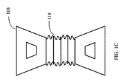
図1Aは、カスタマイズ可能なパルスオキシメトリアセンブリ100を示す。図1Aに示されるように、アセンブリは、ケーブルコネクタ102、光エミッタ104、光センサ106、及びレセプタクル112及び114に接続されたフレキシブルコネクタ110を持つ包帯108を含む。図1Aの光エミッタ104及び光センサ106はそれぞれ、レセプタクル112及び114に取り付けられる。フレキシブルコネクタ110は、患者の身体部分の寸法に適合するよう伸張、収縮、又は歪められることができる。図1Bは、収縮した状態のパルスオキシメトリアセンブリ100を示す。図1Cは、患者の身体部分の物理的寸法を収容するよう、伸びた状態のパルスオキシメトリアセンブリ100を示す。
FIG. 1A shows a customizable
包帯108は、2つのレセプタクル112及び114と、2つのレセプタクル112及び114を接続するフレキシブルコネクタ110とを含む。レセプタクル112及び114は、光エミッタ104及び光センサ106を取り付けるために使用可能である。フレキシブルコネクタ110は、光エミッタ104及び光センサ106の分離及びアラインメントの調整を可能にする。
The
レセプタクル112及び114は、光エミッタ104及び光センサ106をレセプタクル112及び114に固定するためのアタッチメントを更に含む。レセプタクルは、ベルクロ、磁石、ファスナ、ネジ、クランプ、クリップ、フック、ポケット、ストラップ、吸引カップ、ピン、穴、及びスナップといったアタッチメント手段の任意の1つ又は複数を組み込むことができる。アタッチメントを実現するための他の手段が使用されることもできる。
一実施形態では、前述のアタッチメントは、レセプタクルの下側に配置される。結果として、光エミッタ及び光センサは、患者の身体部分と直接接触する。別の実施形態では、アタッチメントは、レセプタクルの外側に配置される。結果として、光エミッタ及び光センサは、上記アタッチメントを介して上記レセプタクルの外側に取り付けられる。レセプタクルが不透明であり、光エミッタ及び光センサが不透明レセプタクルの外側に取り付けられる実施形態では、レセプタクルを介して窓が構築され、光エミッタからの光が患者の身体部分を通って、患者の身体部分から光センサに透過することが可能にされる。 In one embodiment, the aforementioned attachment is located on the underside of the receptacle. As a result, the light emitter and light sensor are in direct contact with the patient's body part. In another embodiment, the attachment is located outside the receptacle. As a result, the light emitter and the light sensor are attached to the outside of the receptacle via the attachment. In embodiments where the receptacle is opaque and the light emitter and light sensor are mounted outside the opaque receptacle, a window is constructed through the receptacle so that light from the light emitter passes through the patient's body part and the patient's body part. To the optical sensor.
フレキシブルコネクタは好ましくは、図1Cに示されるように伸張した状態で、コネクタが、図1Bに示される元の構成にスナップバックしないような物質で作られる。フレキシブルコネクタは、様々な構成をとるように曲げられることができる金属ワイヤ又はワイヤメッシュを含むことができる。屈曲、伸張、ねじれ、収縮、緊張、又はそれらの任意の組み合わせなどのフレキシブルコネクタ及びプローブハウジングの物理的操作は、好ましい実施形態では可逆的である。 The flexible connector is preferably made of a material that, when stretched as shown in FIG. 1C, does not snap back to the original configuration shown in FIG. 1B. The flexible connector can include a metal wire or wire mesh that can be bent to assume a variety of configurations. The physical operation of the flexible connector and probe housing, such as bending, stretching, twisting, contracting, tensioning, or any combination thereof is reversible in the preferred embodiment.
フレキシブルコネクタは、フレキシブルコネクタを保護する軽量のケーシング又はシースを含むことができる。フレキシブルコネクタは好ましくは、丈夫で無毒である1つ又は複数の物質で作られる。例えば、フレキシブルコネクタは、ゴム製ケーシングにより包まれた金属ワイヤを含むことができる。代替的に、フレキシブルコネクタは、プラスチックシース内に閉じ込められたワイヤメッシュを含む。ケーシングの選択は、美学又はフォームファクタに基づかれることができる。医療施設又は機関は、パルスオキシメトリアセンブリの製造業者名、病院、又は製造年月日などのラベル又は他の有用な情報を含むようにケーシングを設計することができる。 The flexible connector can include a lightweight casing or sheath that protects the flexible connector. The flexible connector is preferably made of one or more materials that are strong and non-toxic. For example, the flexible connector can include a metal wire wrapped in a rubber casing. Alternatively, the flexible connector includes a wire mesh confined within a plastic sheath. The choice of casing can be based on aesthetics or form factor. The medical facility or institution can design the casing to include a label or other useful information such as the manufacturer name, hospital, or date of manufacture of the pulse oximetry assembly.
フレキシブルコネクタはまた、ヒンジ又は類似のコネクタにより接続された複数の非可撓性サブ要素を含むことができる。結果として、複数の非可撓性サブ要素は、連続的な態様で枢動可能に相互接続された一連の剛性セグメントの場合に起こり得るように、集合的にフレキシブルである。一連の剛性セグメントは、曲率が変化する馬蹄形に曲げられてもよい。個々のサブ要素のピボットは、医療従事者により設定された曲げ構成を維持するため、ある程度の剛性を更に提供することができる。結果として、ピボットは、相互接続された複数のサブ要素に十分な剛性を与え、問題の物理的な歪み又は操作にかかわらず、それらが全体の形状を保持することが可能にされる。フレキシブルコネクタに使用される剛性セグメントの数は、患者の身体部分の1つ又は複数の寸法に基づき変えられることができる。 The flexible connector can also include a plurality of inflexible sub-elements connected by a hinge or similar connector. As a result, the plurality of inflexible sub-elements are collectively flexible, as can occur with a series of rigid segments pivotally interconnected in a continuous manner. The series of rigid segments may be bent into a horseshoe shape with varying curvature. The pivots of the individual sub-elements can further provide a degree of rigidity to maintain the bending configuration set by the medical personnel. As a result, the pivot provides sufficient rigidity to the interconnected sub-elements and allows them to retain the overall shape regardless of the physical strain or operation in question. The number of rigid segments used in the flexible connector can vary based on one or more dimensions of the patient's body part.
一実施形態では、フレキシブルコネクタは、波形を持つことができる。その結果、フレキシブルコネクタを伸長又は収縮させることで、波形フレキシブルコネクタが収縮、拡張、展開、及び折り畳むことがもたらされる。結果として、波形の隆起部及び溝の少なくとも一部が、患者の身体部分のサイズとほぼ一致するよう重なる。波形の少なくともいくつかの部分は、折り畳まれた波形のフレキシブルコネクタが意図せず展開しないよう、ベルクロタイプのフック及びループを持つことができる。 In one embodiment, the flexible connector can have a corrugation. As a result, extending or contracting the flexible connector results in the corrugated flexible connector contracting, expanding, unfolding, and folding. As a result, at least a portion of the corrugated ridges and grooves overlap to substantially match the size of the patient's body part. At least some portions of the corrugations can have velcro-type hooks and loops to prevent unfolding of the folded corrugated flexible connector.
包帯のフレキシブルコネクタ及び2つのレセプタクルは、フレキシブルコネクタが2つのレセプタクルから取り外せないよう一体化されてもよい。代替的に、フレキシブルコネクタ及びレセプタクルは、互いに取り外し可能であってもよい。取り外し可能又は交換可能なフレキシブルコネクタは、高度のカスタマイズ性を可能にすることができる。なぜなら、ユーザが必要に応じてフレキシブルコネクタ又はレセプタクルを交換することができるからである。 The bandage flexible connector and the two receptacles may be integrated so that the flexible connector cannot be removed from the two receptacles. Alternatively, the flexible connector and the receptacle may be removable from each other. A removable or replaceable flexible connector can allow a high degree of customization. This is because the user can replace the flexible connector or receptacle as necessary.
例えば、ユーザは、短いフレキシブルコネクタをより長いフレキシブルコネクタで置き換える、又は長いフレキシブルコネクタをより短いフレキシブルコネクタで置き換えることができる。ユーザは、磨耗又は汚染されたフレキシブルコネクタを、新しい又は滅菌されたフレキシブルコネクタで置き換えることもできる。反対に、ユーザは、摩耗した又は汚染されたレセプタクルを新しい又は滅菌されたフレキシブルコネクタで置き換えることができる。 For example, a user can replace a short flexible connector with a longer flexible connector, or replace a long flexible connector with a shorter flexible connector. The user can also replace a worn or contaminated flexible connector with a new or sterile flexible connector. Conversely, a user can replace a worn or contaminated receptacle with a new or sterilized flexible connector.
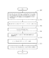
図2は、本発明のパルスオキシメトリアセンブリを使用してパルスオキシメータデータを測定する方法を示す。光エミッタ及び光センサが、最初に、フレキシブルコネクタを含む包帯に取り付けられる(ステップ202)。患者の身体部分の形状及びサイズに適合するよう、アセンブリは、フレキシブルコネクタを介して伸ばされ(ステップ204)、パルスオキシメトリ測定に使用される患者の身体部分に取り付けられる(ステップ206)。アタッチメントが安定し、光エミッタ及び光センサが整列され、患者の身体部分と接触するよう、アセンブリが調整される(ステップ208)。パルスオキシメトリデータの取得は、光センサデータを取得するため、光エミッタ及び光センサを作動させることにより開始される(ステップ210)。その後、取得された光センサデータは、格納又は更なる処理のため、ケーブルコネクタを介して患者モニタに送信される(ステップ212)。 FIG. 2 illustrates a method for measuring pulse oximeter data using the pulse oximetry assembly of the present invention. The light emitter and light sensor are first attached to a bandage that includes a flexible connector (step 202). To fit the shape and size of the patient's body part, the assembly is stretched through a flexible connector (step 204) and attached to the patient's body part used for pulse oximetry measurements (step 206). The assembly is adjusted so that the attachment is stable, the light emitters and light sensors are aligned and in contact with the patient's body part (step 208). Acquisition of pulse oximetry data is initiated by actuating the light emitter and the light sensor to obtain light sensor data (step 210). The acquired optical sensor data is then transmitted to the patient monitor via the cable connector for storage or further processing (step 212).
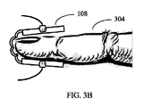
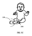
図3A〜図3Cは、様々な患者の身体部分に使用されるカスタマイズ可能なパルスオキシメトリアセンブリの様々な実施形態を示す。図3Aは、小さな指302に取り付けられたパルスオキシメトリアセンブリ100を示す。図3Bは、より大きな指304に取り付けられたパルスオキシメトリアセンブリ100を示す。図3Cは、幼児の足306に取り付けられたパルスオキシメトリアセンブリ100を示す。本発明のパルスオキシメトリアセンブリは、耳、額、鼻及びつま先のような他の患者の身体部分に使用されることもできる。
3A-3C illustrate various embodiments of customizable pulse oximetry assemblies for use with various patient body parts. FIG. 3A shows the
本発明に関する例示的な使用例では、3人の患者が救急室に運ばれる。第1の患者は10歳の子供であり、第2の患者は成人男性であり、第3の患者は乳児である。医療従事者は、最初の患者にアテンドし、最初に包帯を選択し、光エミッタ及び光センサを包帯に取り付けることにより、パルスオキシメータアセンブリを準備する。包帯は、その後、子供の指に付けられる。包帯は、子供の指の形状及びサイズに適合するよう調節される。その後、医療従事者は、子供の血液酸素飽和レベルを測定する。 In an exemplary use in connection with the present invention, three patients are brought to the emergency room. The first patient is a 10 year old child, the second patient is an adult male, and the third patient is an infant. The health care professional prepares the pulse oximeter assembly by attending to the first patient, selecting the bandage first, and attaching the light emitter and light sensor to the bandage. The bandage is then applied to the child's finger. The bandage is adjusted to fit the shape and size of the child's fingers. Thereafter, the health professional measures the blood oxygen saturation level of the child.
測定後、医療従事者は第2の患者にアテンドする。医療従事者は、成人患者に対して同じパルスオキシメトリアセンブリを使用する。パルスオキシメトリアセンブリは、最初に消毒剤で拭き取られ、その後、指といった第2の患者の身体部分を収容するよう、フレキシブルコネクタが伸長される。この指は、最初の患者のよりも大きいであろう。その後、パルスオキシメータデータが測定される。 After the measurement, the healthcare worker attends a second patient. Health care workers use the same pulse oximetry assembly for adult patients. The pulse oximetry assembly is first wiped with a disinfectant and then the flexible connector is extended to accommodate a second patient body part, such as a finger. This finger will be larger than the first patient. Thereafter, pulse oximeter data is measured.
次いで、医療従事者は、幼児患者のパルスオキシメトリ測定を行う。医療従事者は、消毒後、同じ光エミッタ及び光センサを使用することを決定するが、感染を最小限に抑えるため、幼児のための新しい包帯を使用する。その後、医療従事者は、フレキシブルコネクタを伸ばして幼児の足にフィットさせ、幼児のパルスオキシメトリデータを取得する。 The health care worker then performs pulse oximetry measurements on the infant patient. The health care professional decides to use the same light emitter and light sensor after disinfection, but uses a new bandage for the infant to minimize infection. Thereafter, the medical staff extends the flexible connector to fit the infant's foot, and acquires the infant's pulse oximetry data.
各パルスオキシメータデータを取得した後、医療従事者は、取得したデータを表示して処理するため、救急室のデスクトップコンピュータに取得したデータを転送する。医療従事者は、デスクトップコンピュータにおいて様々なデータを見て、そのデータを分析し、診断に達し、所見及びコメントをそれぞれの患者記録に入力する。使用されたパルスオキシメトリアセンブリ要素は、廃棄されるか、又は別の患者に再使用するため滅菌されることができる。 After acquiring each pulse oximeter data, the health professional transfers the acquired data to the desktop computer in the emergency room to display and process the acquired data. The healthcare professional views various data on the desktop computer, analyzes the data, reaches a diagnosis, and enters findings and comments into each patient record. The used pulse oximetry assembly element can be discarded or sterilized for reuse in another patient.
パルスオキシメトリアセンブリは、フレキシブルディスプレイ、フレキシブル電源、フレキシブル光源、及びフレキシブルセンサなどのフレキシブル電子要素を含むことができる。一実施形態では、光センサと光エミッタとは共に可撓性であり、パルスオキシメトリアセンブリを患者の身体部分にフィットさせるときの調整を容易にする。別の実施形態では、レセプタクルは、光エミッタ及び光センサのアラインメントの程度を示すため、可撓性OLEDディスプレイなどの視覚的表示を提供するフレキシブルディスプレイを含むことができる。光エミッタ及び光センサは、包帯のレセプタクルに埋め込まれた可撓性バッテリにより電力を供給されてもよい。 The pulse oximetry assembly can include flexible electronic elements such as flexible displays, flexible power sources, flexible light sources, and flexible sensors. In one embodiment, both the light sensor and the light emitter are flexible to facilitate adjustment when fitting the pulse oximetry assembly to the patient's body part. In another embodiment, the receptacle can include a flexible display that provides a visual indication, such as a flexible OLED display, to indicate the degree of alignment of the light emitter and light sensor. The light emitter and light sensor may be powered by a flexible battery embedded in the bandage receptacle.
本発明は、上述した本発明のいくつかの例示的な実施形態に限定されるものではない。当業者であれば想像される他の変形も、本開示の範囲に含まれることが意図される。 The present invention is not limited to the several exemplary embodiments of the invention described above. Other variations envisioned by those skilled in the art are also intended to be included within the scope of the present disclosure.
Claims (15)
第1のレセプタクル及び第2のレセプタクルを備える包帯と、
前記第1のレセプタクル及び前記第2のレセプタクルを接続するフレキシブルコネクタと、
前記第1のレセプタクルに光エミッタを取り外し可能に取り付ける第1のプローブハウジングを含む光エミッタと、
前記第2のレセプタクルに取り外し可能に取り付けられる第2のプローブハウジングを含む光センサと、
前記光エミッタ及び前記光センサを物理的に結合し、更に前記光エミッタ及び前記光センサを患者モニタに通信可能に結合するケーブルコネクタとを有し、
前記フレキシブルコネクタ、前記第1のプローブハウジング、及び前記第2のプローブハウジングが、患者の身体部分の寸法から生じる前記光エミッタと前記光センサとの間の分離及びアラインメントに関して調整され、
前記第1のレセプタクル、前記第2のレセプタクル、及び前記フレキシブルコネクタは、個別に取り外し可能である、パルスオキシメトリアセンブリ。 Customizable pulse oximetry assembly,
A bandage comprising a first receptacle and a second receptacle;
A flexible connector connecting the first receptacle and the second receptacle;
A light emitter including a first probe housing removably attaching the light emitter to the first receptacle;
An optical sensor including a second probe housing removably attached to the second receptacle;
A cable connector for physically coupling the light emitter and the light sensor and further communicatively coupling the light emitter and the light sensor to a patient monitor;
The flexible connector, the first probe housing, and the second probe housing are adjusted for separation and alignment between the light emitter and the light sensor resulting from dimensions of a patient's body part;
The pulse oximetry assembly, wherein the first receptacle, the second receptacle, and the flexible connector are individually removable.
Applications Claiming Priority (3)
| Application Number | Priority Date | Filing Date | Title |
|---|---|---|---|
| EP16161070 | 2016-03-18 | ||
| EP16161070.4 | 2016-03-18 | ||
| PCT/EP2016/078519 WO2017089374A1 (en) | 2015-11-24 | 2016-11-23 | Pulse oximeter using disposable multi-material stretch bandage |
Publications (1)
| Publication Number | Publication Date |
|---|---|
| JP2019502422A true JP2019502422A (en) | 2019-01-31 |
Family
ID=55640548
Family Applications (1)
| Application Number | Title | Priority Date | Filing Date |
|---|---|---|---|
| JP2018524349A Withdrawn JP2019502422A (en) | 2016-03-18 | 2016-11-23 | Pulse oximeter using disposable multi-material stretch bandage |
Country Status (5)
| Country | Link |
|---|---|
| EP (1) | EP3380012A1 (en) |
| JP (1) | JP2019502422A (en) |
| CN (1) | CN108289645A (en) |
| BR (1) | BR112018010301A2 (en) |
| WO (1) | WO2017089374A1 (en) |
Cited By (1)
| Publication number | Priority date | Publication date | Assignee | Title |
|---|---|---|---|---|
| JP7474778B2 (en) | 2019-03-07 | 2024-04-25 | コーニンクレッカ フィリップス エヌ ヴェ | Apparatus for monitoring oxygen saturation in clinical conditions - Patent application |
Family Cites Families (11)
| Publication number | Priority date | Publication date | Assignee | Title |
|---|---|---|---|---|
| US4260951A (en) * | 1979-01-29 | 1981-04-07 | Hughes Aircraft Company | Measurement system having pole zero cancellation |
| US4685464A (en) * | 1985-07-05 | 1987-08-11 | Nellcor Incorporated | Durable sensor for detecting optical pulses |
| DE3809084C2 (en) * | 1988-03-18 | 1999-01-28 | Nicolay Gmbh | Sensor for the non-invasive measurement of the pulse frequency and / or the oxygen saturation of the blood and method for its production |
| DE3810411A1 (en) * | 1988-03-26 | 1989-10-12 | Nicolay Gmbh | DEVICE FOR FIXING A SENSOR, IN PARTICULAR A SENSOR FOR OXIMETRIC MEASUREMENTS |
| US5991648A (en) * | 1998-03-30 | 1999-11-23 | Palco Labs, Inc. | Adjustable pulse oximetry sensor for pediatric use |
| US7245953B1 (en) | 1999-04-12 | 2007-07-17 | Masimo Corporation | Reusable pulse oximeter probe and disposable bandage apparatii |
| ES2213472B1 (en) * | 2002-12-26 | 2005-11-01 | Carril Cables Y Sensores, S.L. | OXYMETRY SENSOR. |
| US7869850B2 (en) * | 2005-09-29 | 2011-01-11 | Nellcor Puritan Bennett Llc | Medical sensor for reducing motion artifacts and technique for using the same |
| US8600467B2 (en) * | 2006-11-29 | 2013-12-03 | Cercacor Laboratories, Inc. | Optical sensor including disposable and reusable elements |
| US8577435B2 (en) * | 2011-03-31 | 2013-11-05 | Covidien Lp | Flexible bandage ear sensor |
| CN102579053A (en) * | 2012-03-02 | 2012-07-18 | 天津大学 | Reflective pulse blood oxygen detecting method based on diffusion theory |
-
2016
- 2016-11-23 JP JP2018524349A patent/JP2019502422A/en not_active Withdrawn
- 2016-11-23 WO PCT/EP2016/078519 patent/WO2017089374A1/en active Application Filing
- 2016-11-23 CN CN201680068651.1A patent/CN108289645A/en active Pending
- 2016-11-23 EP EP16801183.1A patent/EP3380012A1/en not_active Withdrawn
- 2016-11-23 BR BR112018010301A patent/BR112018010301A2/en not_active Application Discontinuation
Cited By (1)
| Publication number | Priority date | Publication date | Assignee | Title |
|---|---|---|---|---|
| JP7474778B2 (en) | 2019-03-07 | 2024-04-25 | コーニンクレッカ フィリップス エヌ ヴェ | Apparatus for monitoring oxygen saturation in clinical conditions - Patent application |
Also Published As
| Publication number | Publication date |
|---|---|
| EP3380012A1 (en) | 2018-10-03 |
| BR112018010301A2 (en) | 2018-12-04 |
| CN108289645A (en) | 2018-07-17 |
| WO2017089374A1 (en) | 2017-06-01 |
Similar Documents
| Publication | Publication Date | Title |
|---|---|---|
| US11534110B2 (en) | Nose sensor | |
| US20210369204A1 (en) | Gear for holding a physiological sensor | |
| US8145288B2 (en) | Medical sensor for reducing signal artifacts and technique for using the same | |
| US9924902B2 (en) | Neck-worn physiological monitor | |
| US20070244377A1 (en) | Pulse oximeter sleeve | |
| US7680522B2 (en) | Method and apparatus for detecting misapplied sensors | |
| US20100249557A1 (en) | Medical sensor with flexible components and technique for using the same | |
| US20190343432A1 (en) | Non-invasive hemoglobin and white blood cell sensors | |
| US11331015B2 (en) | Pulse oximeter sensor | |
| US20140275883A1 (en) | Wireless sensors | |
| US20170172516A1 (en) | Neck-worn physiological monitor | |
| US20170172515A1 (en) | Neck-worn physiological monitor | |
| US20200253516A1 (en) | Pulse oximeter using disposable multi-material stretch bandage | |
| US20170172427A1 (en) | Neck-worn physiological monitor | |
| US20170172423A1 (en) | Neck-worn physiological monitor | |
| US20170172428A1 (en) | Neck-worn physiological monitor | |
| JP2019502422A (en) | Pulse oximeter using disposable multi-material stretch bandage | |
| JP2018534020A (en) | Physiological monitoring kit with USB drive | |
| US20210386337A1 (en) | Waveguide-based pulse oximetry sensor | |
| US20160022183A1 (en) | Pulse oximeter sensor with reversible connector assembly |
Legal Events
| Date | Code | Title | Description |
|---|---|---|---|
| A621 | Written request for application examination |
Free format text: JAPANESE INTERMEDIATE CODE: A621 Effective date: 20190905 |
|
| A761 | Written withdrawal of application |
Free format text: JAPANESE INTERMEDIATE CODE: A761 Effective date: 20200409 |