JP2019221003A - Speaker device - Google Patents
Speaker device Download PDFInfo
- Publication number
- JP2019221003A JP2019221003A JP2019183399A JP2019183399A JP2019221003A JP 2019221003 A JP2019221003 A JP 2019221003A JP 2019183399 A JP2019183399 A JP 2019183399A JP 2019183399 A JP2019183399 A JP 2019183399A JP 2019221003 A JP2019221003 A JP 2019221003A
- Authority
- JP
- Japan
- Prior art keywords
- vibration
- vibration device
- frame
- diaphragm
- elastic body
- Prior art date
- Legal status (The legal status is an assumption and is not a legal conclusion. Google has not performed a legal analysis and makes no representation as to the accuracy of the status listed.)
- Pending
Links
Images


Abstract
Description
本発明は、スピーカー装置に関するものである。 The present invention relates to a speaker device.
従来、スピーカー装置として各種のものが提案されている。例えば特許文献1には、スピーカー装置が開示されている。このスピーカー装置は、アクチュエーターのボイスコイルを保護する弾性材でできたキャップに一端が設けられた筒状の駆動部材の他端に駆動部材を覆うように設けられた増幅手段と、増幅手段に設けられた伝達手段とからなり、ボイスコイルの端部と駆動部材の端部はキャップを挟んで対向して配置されている。
Conventionally, various types of speaker devices have been proposed. For example,
しかし、特許文献1に開示されたスピーカー装置は、放射板に連結され振動を発生した場合に、放射板に連結された駆動軸の動作方向以外の動きを阻止する方策は施されていないため、音量を得ようとした場合に、駆動軸の動作方向以外の動きが発生して、音の伝達効率が低下する傾向があるという問題点があった。
However, the speaker device disclosed in
本発明は、振動装置から発生した振動を効率よく振動板に伝達することができ、音量が確保され、広い音域のクリアな音を出すことができるスピーカー装置を提供することを目的とするものである。 An object of the present invention is to provide a speaker device capable of efficiently transmitting vibration generated from a vibration device to a diaphragm, securing a sound volume, and emitting clear sound in a wide range. is there.
本発明のスピーカー装置は、振動板の一方の平面側に振動装置が当接され、該振動装置から伝達された振動を上記振動板から音として放射するスピーカー装置であって、該スピーカー装置は、上記振動板と、上記振動装置と、上記振動装置を囲むように上記振動板に設けられた枠体と、上記枠体と上記振動装置を挟んで上記振動板の上記平面側に対向して設けられた弾性体とを備えてなり、上記枠体は、上記振動装置の外周との間に隙間を有して設けられ、上記弾性体は、上記枠体と上記振動装置に跨って、該枠体と該振動装置に固着されており、上記枠体と上記振動装置と上記弾性体とが一体化されていることを特徴とする。 The speaker device of the present invention is a speaker device in which a vibration device is in contact with one flat surface side of a diaphragm, and radiates vibration transmitted from the vibration device as sound from the diaphragm, and the speaker device includes: The vibrating plate, the vibrating device, a frame provided on the vibrating plate so as to surround the vibrating device, and a frame provided facing the flat side of the vibrating plate with the frame and the vibrating device interposed therebetween. The frame body is provided with a gap between the outer periphery of the vibrating device, and the elastic body extends over the frame body and the vibrating device. The frame is fixed to the vibration device, and the frame, the vibration device, and the elastic body are integrated.
上記振動装置および上記枠体における上記振動板の上記平面側の対向側の面全体が、上記弾性体に固着されていることを特徴とする。 The entire surface of the vibration device and the frame on the side opposite to the plane of the vibration plate is fixed to the elastic body.
上記振動装置の外周形状が、略円柱状であり、上記枠体の上記振動装置側の内周形状が、上記振動装置の外周形状に対向する略円筒状であり、上記振動装置の駆動軸が該振動装置の中央に設けられ、上記枠体の内周と上記振動装置の外周との間の径方向隙間が、周方向全域で一定であることを特徴とする。 The outer peripheral shape of the vibrating device is substantially cylindrical, the inner peripheral shape of the frame on the vibrating device side is a substantially cylindrical shape facing the outer peripheral shape of the vibrating device, and the driving shaft of the vibrating device is A radial gap provided between the inner periphery of the frame and the outer periphery of the vibrating device is provided at the center of the vibrating device, and is characterized by being constant throughout the circumferential direction.
上記振動装置は、該振動装置の作動時に該振動装置の駆動軸の軸方向に付勢力が発生するように、該駆動軸の端部が上記振動板の上記平面側に当接されていることを特徴とする。 In the vibration device, an end of the drive shaft is in contact with the flat surface of the vibration plate so that a biasing force is generated in an axial direction of a drive shaft of the vibration device when the vibration device is operated. It is characterized by.
上記スピーカー装置は、上記振動板に当接される他の振動部材を備えることを特徴とする。 The speaker device includes another vibration member that is in contact with the diaphragm.
本発明に係るスピーカー装置は、振動板の一方の平面側に振動装置が当接され、振動装置から伝達された振動を振動板から音として放射する装置であり、振動板と、振動装置と、振動装置を囲むように振動板に設けられた枠体と、枠体と振動装置を挟んで振動板の平面側に対向して設けられた弾性体とを備えてなり、枠体は、振動装置の外周との間に隙間を有して設けられ、弾性体は、枠体と振動装置に跨って、枠体と振動装置に固着されており、枠体と振動装置と弾性体とが一体化されているので、弾性体において、振動装置の作動時に振動装置の駆動軸方向の動作に追従した動作が発生し、この弾性体が、振動装置と枠体との並設方向への振動装置の動きを阻止するとともに、振動装置に対して該振動装置の駆動軸方向の付勢力を付加させる。これにより、振動装置に当接された振動板に、該振動装置から発生した振動が効率よく伝達され、音量が確保され、広い音域のクリアな音を出すことができる。 The speaker device according to the present invention is a device in which a vibration device is in contact with one flat surface side of the vibration plate, and radiates vibration transmitted from the vibration device as sound from the vibration plate. A frame provided on the diaphragm so as to surround the vibrating device, and an elastic body provided on the plane side of the diaphragm with the frame and the vibrating device interposed therebetween. The elastic body is fixed to the frame body and the vibration device so as to straddle the frame body and the vibration device, and the frame body, the vibration device, and the elastic body are integrated. When the vibration device is activated, an operation follows the operation of the vibration device in the drive axis direction, and the elastic body moves the vibration device in the direction in which the vibration device and the frame are juxtaposed. In addition to preventing movement, a biasing force is applied to the vibration device in the drive axis direction of the vibration device. That. Thus, the vibration generated from the vibration device is efficiently transmitted to the vibration plate in contact with the vibration device, the sound volume is secured, and clear sound in a wide sound range can be emitted.
また、振動装置および枠体における振動板の平面側の対向側の面全体が、弾性体に固着する構成の場合では、弾性体が、振動装置と枠体との並設方向への振動装置の動きをより防止でき、かつ、振動装置に対して該振動装置の駆動軸方向の付勢力を無駄なく付加できる。 In the case where the entire surface of the vibrating device and the frame on the side opposite to the plane of the vibrating plate is fixed to the elastic body, the elastic body moves the vibrating device in the direction in which the vibrating device and the frame are juxtaposed. The movement can be further prevented, and the urging force in the drive axis direction of the vibration device can be applied to the vibration device without waste.
また、振動装置の外周形状が、略円柱状であり、枠体の振動装置側の内周形状が、振動装置の外周形状に対向する略円筒状であり、振動装置の駆動軸が該振動装置の中央に設けられ、枠体の内周と振動装置の外周との間の径方向隙間が、周方向全域で一定である構成の場合では、弾性体による上記付勢力の歪みがなくなり、該振動装置から発生した振動が、より効率よく振動板に伝達される。このため、音量がより確保され、広い音域のよりクリアな音を出すことができる。 Further, the outer peripheral shape of the vibrating device is substantially cylindrical, the inner peripheral shape of the frame body on the vibrating device side is a substantially cylindrical shape opposed to the outer peripheral shape of the vibrating device, and the driving shaft of the vibrating device is In the case where the radial gap between the inner circumference of the frame and the outer circumference of the vibration device is constant in the entire circumferential direction, the biasing force due to the elastic body is eliminated, and the vibration is reduced. The vibration generated from the device is transmitted to the diaphragm more efficiently. For this reason, the sound volume is further secured, and a clearer sound in a wider range can be produced.
また、振動装置が、その作動時にその駆動軸の軸方向に付勢力が発生するように、駆動軸の端部が振動板の上記平面側に当接されている構成の場合では、振動板に当接する駆動軸の端部が浮上せず、振動装置で発生した振動が振動板に継続的に伝達される。また、駆動軸の端部の当接部分の接触点において点音源となり、振動装置で発生した振動を集中的に受けて強い振動となる。 Further, in the case where the vibration device has a configuration in which the end of the drive shaft is in contact with the flat surface of the vibration plate so that an urging force is generated in the axial direction of the drive shaft when the vibration device operates, the vibration device The end of the drive shaft that abuts does not float, and the vibration generated by the vibration device is continuously transmitted to the diaphragm. Further, it becomes a point sound source at the contact point of the abutting portion at the end of the drive shaft, and receives the vibration generated by the vibration device intensively, resulting in strong vibration.
また、スピーカー装置が、上記振動板に当接される他の振動部材を備える構成の場合では、第2の振動板、壁、天井、床、または家具などの他の振動部材から、音量が確保された、広い音域のクリアな音を出すことができる。 In the case where the speaker device includes another vibration member that is in contact with the diaphragm, the volume is secured from another vibration member such as the second diaphragm, a wall, a ceiling, a floor, or furniture. It can produce clear sound in a wide range.
以下、本発明を実施するための形態を説明する。
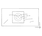
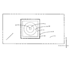
図1及至図3は、本発明のスピーカー装置の第1実施例を示す図である。
スピーカー装置1は、振動板2の一方の平面側に振動装置3が当接され、振動装置3から伝達された振動を振動板2から音として放射する装置である。スピーカー装置1は、振動板2と、振動装置3と、振動装置3を取り囲むように振動板2に設けられた枠体4と、枠体4と振動装置3を挟んで振動板2の上記平面側に対向して設けられた弾性体5とを備えている。枠体4は、振動装置3の外周との間に隙間32を有して設けられている。弾性体5は、枠体4と振動装置3に跨って、枠体4と振動装置3に固着されている。これにより、枠体4と振動装置3と弾性体5とが一体化されている。振動装置3は、駆動軸31を有し、この端部が振動板2に当接されている。駆動軸31は、振動装置3に固定され、振動装置3と一体化されている。この形態では、振動板2に対して振動装置3が1つ設けられているが、これに限定されず、複数の振動装置3を設けることも可能である。
Hereinafter, embodiments for implementing the present invention will be described.
FIGS. 1 to 3 are views showing a first embodiment of the speaker device of the present invention.
The
図1及至図3のように、振動板2には、振動装置3の振動の中心軸上の近傍に設けられた略円柱状の駆動軸31が当接されている。駆動軸31は、その軸方向が図中のZ方向に沿った方向であり、振動板2の平面(XY方向平面)とは、その端部が略垂直に当接している。振動装置3で発生した振動は、振動板2における駆動軸31の当接した部分に集中するように設計されている。このため、振動装置3は、微弱振動であっても効率よく振動板2に振動を伝達することができる。また、振動板2には、振動装置3を取り囲むように配置された枠体4と、振動装置3とが、振動装置3の振動板2に当接された駆動軸31の側と反対側の面が弾性体5を介して枠体4に連結されて設けられている。弾性体5は、駆動軸31の動作に追従して動作するようになっており、振動板2と枠体4と振動装置3と弾性体5は一体化されている。このようにした場合は、振動装置3から発生した振動を継続的に効率よく振動板に伝達することができ、音量が確保され、広い音域のクリアな音を出すことができる。
As shown in FIGS. 1 to 3, a substantially
しかし、枠体4と振動装置3と弾性体5とを一体化しなかった場合は、振動装置3は、振動装置3が作動した時に振動板2に当接された駆動軸31の当接箇所を支点として振り子のような動作が発生して駆動軸31のZ方向の駆動軸上の動作を阻害することが懸念される。この結果、振動装置3から発生した振動を継続的に効率よく振動板に伝達することができなくなるおそれがある。
However, when the
振動装置3の駆動軸31は、振動板2に当接した箇所が固定されていても、固定されずに静置した状態でも、弾性体5が設けられていることによって同等の効果が得られる。
The same effect can be obtained by the provision of the
図1及至図3に示すように、弾性体5は、振動板2に設けられた枠体4と、振動装置3の外周に均一になるように配置された隙間32と、振動装置3とを覆うように、振動板2に対して枠体4を挟んで対面する側の振動装置3と枠体4のX方向およびY方向の全面にわたって設けられている。詳細には、振動装置3の外周形状が、略円柱状であり、枠体4の振動装置3側の内周形状が、振動装置3の外周形状に対向する略円筒状であり、振動装置3の駆動軸31が振動装置3の中央に設けられ、枠体4の内周と振動装置3の外周との間の径方向の隙間32が、周方向全域で一定である。振動装置3および枠体4における振動板2の平面側(振動装置が当接する側)の対向側の面全体(X方向およびY方向の全面)が、弾性体5に固着されている。このような均一な隙間を設けることで、弾性体による後述の付勢力の歪みがなくなり、該振動装置から発生した振動が、より効率よく振動板に伝達される。
As shown in FIGS. 1 to 3, the
本発明のスピーカー装置では、内部応力(張力や撓み)が無い状態で、枠体4と振動装置3とを、弾性体5に固着させることで連結している。固着方法は特に限定されないが、接着剤の塗布による接着、両面テープによる接着、部材間の溶融接着など、任意の方法を採用できる。特に、振動装置3および枠体4における振動板2の平面側の対向側の面全体(X方向およびY方向の全面)を、接着剤や両面テープを用いて均一な接着力で、弾性体5に固着することが好ましい。なお、ビスなどでの数か所のみの固定の場合、弾性体による後述する付勢力が十分に得られない、または、該付勢力に歪み(X方向やY方向)が生じるおそれがある。枠体4および振動装置3との固着の際に、弾性体5の全面に両面テープ等を貼り付けておくことで、弾性体5の隙間32にかかる部分は、その粘着剤などがそのまま露出した状態となる。この部分に、振動板2と枠体4と弾性体5で囲まれた空間内に混入した小さなゴミなどが吸着され、音への悪影響を低減できる。
In the speaker device of the present invention, the
上記構成の如く弾性体5を設けた場合、振動装置3が作動しない状態では弾性体5のX方向、Y方向、およびZ方向のいずれの方向にも付勢力となる応力は働かず振動装置3は安定している。振動装置3の作動時には、弾性体5にX方向、Y方向、およびZ方向に動作が加わり内部応力が発生し、振動装置3のX方向およびY方向の動作には隙間32に張力と撓みになるような動作が同時に働く。弾性体5に発生した内部応力は隙間32の部分で緩和され、振動装置3と枠体4との並設方向(X方向およびY方向)の振動装置3の動きは阻止され安定する。一方、振動装置3で発生した振動の駆動軸31のZ方向(図1及至図3)の動作に弾性体5は追従して動作するので、弾性体5に内部応力が発生する。弾性体5は、枠体4および振動装置3と均一な接着力の全面接着などによって固着されているので、内部応力に対する反発力が発生して、この反発力が振動装置3に対する付勢力となる。
When the
また、上述のように、弾性体5は、振動装置3の作動時に、振動装置3の駆動軸31のZ方向の動作に連動して追従した動作が発生し、弾性体5には内部応力が発生して、該内部応力のZ方向(図1及至図3)の反発力が振動装置3に付加される付勢力として働く。この付勢力により、振動装置3の振動板2に当接する部分が浮上せず、振動装置3で発生した振動を振動板2に継続的に伝達させるようにできる。また、上記付勢力は、X方向やY方向へのずれがなく、駆動軸31の振動方向であるZ方向への力である。これらの結果、振動装置3で発生した振動を効率よく振動板2に伝達することができ、音量が確保され、広い音域のクリアな音を出すことができる。特に、振動装置の振動が微弱振動である場合でも、広い音域のクリアな音を出すことができる。
Further, as described above, when the
弾性体5としては、上述の振動装置3と枠体4との並設方向の振動装置3の動きの阻害と、振動装置3の駆動軸31の振動動作への追従が可能であれば特に限定されない。例えば、ゴムを用いて所定厚みのシート状に形成されたものがよい。より具体的な例としては、ゴムを用いた厚み1mmから10mm程度のシート状であり、好ましくは厚み3mmに調整された発泡性の天然ゴムをシート状に形成した材料を用いて、枠体4の外形に合わせた形状に加工されたものがよい。また、類似の機能を有する材料を用いて形成することも可能である。
The
枠体4としては、振動板2に用いられる材料で形成されたものがよい。形状としては、図1及至図3に例示するようなものが好ましい。すなわち、静置時における弾性体5が振動板2と平行な平板シート状であり、弾性体5の枠体4および振動装置3との固着面が振動板2に平行な面である。詳細には、枠体4のZ方向の寸法は、振動装置3を振動板2に静置させた時に得られる振動装置3の駆動軸31が設けられた面と反対側の面が、振動板2に平行し、枠体4の振動板2の側の面と反対側の面と同一面になるようにして、弾性体5を設けた場合に、弾性体5のZ方向に内部応力が加わらないようにした寸法とすることが好ましい。また、枠体4の平面形状は、振動装置3の平面寸法の概2倍程度の寸法を一辺とする正方形に形成されたものが好ましい。
The
振動板2は、振動装置3からの振動が伝達され音として放射される部材であればよい。例えば、その全体にスムーズに振動が伝達され音として放射される硬質の板材(平板状)を用いる。硬質の板材の平板の材質としては、木材、木質材料、竹、石膏ボード、金属、ガラス、硬質プラスチックなどが例示される。これらの中でも、振動板2は、建築物から廃棄される建材などの木材を使用することが好ましい。
The
振動板2は、例えば、硬質の板材(木材)で形成されている。硬質の木材とは、充分に乾燥した木材であって、大気の温度や湿度に応じて一定の含水率で平衡状態に達したものであり、充分な乾燥によって木材の細胞は収縮する。また、建築物から廃棄される木材の場合、建築として使用されていた期間に木材は充分に乾燥し古材となり、時間の経過による自然乾燥によって木材の収縮が促進し、さらに空気や紫外線に触れることによって、木材は酸化して古材は硬質の木材となる。このような木材を用いて形成された振動板2は、振動装置3の駆動軸31の端部が当接部分の接触点において点音源となりやすく、振動装置3で発生した振動を集中的に受けて強い振動となり、振動板2の全体にスムーズに振動が伝達される。
The
また、振動板2は、気乾比重が0.3〜0.65程度の針葉樹を用いて、柾目に形成されていることが好ましい。この場合、年輪の繊維によって振動は伝達され、振動板2の全体で増幅され音として放射されるので、成長量の小さい冬目の硬い部分からは高音が出やすく、成長量の大きい夏目の柔らかい部分からは低音が出やすくなり、高音と低音がミックスされた振動が発生しやすい。また、このような木材の振動板2は、適度な粘性を有しており、表面の反発係数は金属製や硬質プラスチック製のものよりも低い。このため、瞬間的な外力による加振と、継続的な励振とのいずれによって振動板2を振動させた場合でも、放射される音は高周波成分の少ない「柔らかい音」の音量が得られる。また、振動装置を増幅装置として用いて、さらなる大きな他の振動部材(第2の振動板、壁、天井、床、または家具など)に当接させてスピーカー装置として用いることも可能である。
In addition, it is preferable that the
上記のような振動部材を含む場合、振動部材も含めた全体が本発明のスピーカー装置となる。振動板2に当接される振動部材には、骨伝導によって振動装置3から発生した音が伝達される。このため、振動部材の材質としては、硬質な板材に限定されず柔軟な材料であっても使用できる。例えば、織物、紙、プラスチックシート、壁紙やクロスなどであり、形状としてはカーテン状や幕状とできる。なお、本発明における振動板2についても、振動装置3からの振動が伝達され音として放射される部材であれば、このような柔軟な材料からなる部材としてもよい。
When the above-described vibration member is included, the entire speaker device including the vibration member is the speaker device of the present invention. The sound generated from the
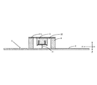
図4及至図5は、本発明のスピーカー装置の第2実施例を示す図である。
このスピーカー装置は、駆動軸31の端部が振動板2に当接する面積を大きくして振動装置3を振動板2に静置した例である。駆動軸31は、略円柱状の本体の一端に円板状の鍔部が設けられた構造である。この鍔部が駆動軸31の端部であり、該鍔部の円板平面が振動板2に当接している。駆動軸31以外の構成は、図1及至図3の実施形態と同様である。また、第1実施例および第2実施例のいずれの場合においても、振動板2において、駆動軸31の端部に対応する凹部を形成し、これに駆動軸31の端部を嵌合させてもよい。これにより組み立て時の位置決めが容易となり、作業性が向上する。
FIGS. 4 to 5 are diagrams showing a second embodiment of the speaker device of the present invention.
This speaker device is an example in which the area where the end of the
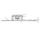
図6及至図7は、本発明のスピーカー装置の第3実施例を示す図である。
このスピーカー装置は、駆動軸31の端部が振動板2に当接する面積を大きくして振動装置3を振動板2に固定し、かつ、枠体4に補助部材41を設けた例である。補助部材41は、枠体4において、振動装置3を振動板2に静置させた時に得られる振動装置3の駆動軸31が設けられた面と反対側の面が、振動板2に平行し、枠体4の振動板2の側の面と反対側の面と同一面になるように簡易に寸法が調整できるようにする部材である。駆動軸31と枠体4と補助部材41以外の構成は、図1及至図3の実施形態と同様である。また、駆動軸31の詳細構成は、図4及至図5の実施形態と同様である。
6 to 7 are views showing a third embodiment of the speaker device of the present invention.
This speaker device is an example in which the area where the end of the
以上、本発明を添付図面に示す実施形態に基づいて説明したが、本発明は上記各例の実施形態に限定されるものではなく、本発明の意図する範囲内であれば、適宜の設計変更を行うことが可能である。 As described above, the present invention has been described based on the embodiments shown in the accompanying drawings. However, the present invention is not limited to the above embodiments, and appropriate design changes may be made within the intended scope of the present invention. It is possible to do.
本発明のスピーカー装置は、振動装置から発生した振動を効率よく振動板に伝達することができ、音量が確保され、広い音域のクリアな音を出すことができるので、室内、室外、大型、小型など、様々な用途におけるスピーカー装置として広く利用できる。 The speaker device of the present invention can efficiently transmit the vibration generated from the vibrating device to the diaphragm, secure the volume, and emit clear sound in a wide range, so that the speaker device can be used indoors, outdoors, large and small. It can be widely used as a speaker device for various applications.
1 スピーカー装置
2 振動板
3 振動装置
4 枠体
5 弾性体
31 駆動軸
32 隙間
41 補助部材
DESCRIPTION OF
Claims (6)
該スピーカー装置は、前記振動板と、前記振動装置と、前記振動装置を囲むように前記振動板に設けられた枠体と、前記枠体と前記振動装置を挟んで前記振動板の前記平面側に対向して設けられた弾性体とを備えてなり、
前記枠体は、前記振動装置の外周との間に隙間を有して設けられ、
前記弾性体は、前記枠体と前記振動装置に跨って、該枠体と該振動装置に固着されており、
前記枠体と前記振動装置と前記弾性体とが一体化されていることを特徴とするスピーカー装置。 A vibration device is abutted on one plane side of the diaphragm, a speaker device that radiates vibration transmitted from the vibration device as sound from the diaphragm,
The speaker device includes the diaphragm, the vibration device, a frame provided on the diaphragm so as to surround the vibration device, and a flat surface of the diaphragm sandwiching the frame and the vibration device. And an elastic body provided to face the
The frame is provided with a gap between the outer periphery of the vibration device,
The elastic body straddles the frame and the vibration device, and is fixed to the frame and the vibration device,
A speaker device, wherein the frame, the vibration device, and the elastic body are integrated.
前記枠体の前記振動装置側の内周形状が、前記振動装置の外周形状に対向する略円筒状であり、
前記振動装置の駆動軸が該振動装置の中央に設けられ、前記枠体の内周と前記振動装置の外周との間の径方向隙間が、周方向全域で一定であることを特徴とする請求項1記載のスピーカー装置。 The outer peripheral shape of the vibrating device is substantially cylindrical,
The inner peripheral shape of the frame on the vibrating device side is a substantially cylindrical shape facing the outer peripheral shape of the vibrating device,
A drive shaft of the vibration device is provided at a center of the vibration device, and a radial gap between an inner periphery of the frame body and an outer periphery of the vibration device is constant in an entire circumferential direction. Item 7. The speaker device according to Item 1.
前記振動装置の外周形状が、略円柱状であり、
前記枠体の前記振動装置側の内周形状が、前記振動装置の外周形状に対向する略円筒状であり、
前記振動装置の駆動軸が該振動装置の中央に設けられ、前記枠体の内周と前記振動装置の外周との間の径方向隙間が、周方向全域で一定であり、
前記振動装置は、該振動装置の作動時に該振動装置の駆動軸の軸方向に付勢力が発生するように、該駆動軸の端部が前記振動板の前記平面側に当接されていることを特徴とする請求項1記載のスピーカー装置。 The entire surface of the vibration device and the frame on the side opposite to the flat surface of the vibration plate is bonded and fixed to the elastic body,
The outer peripheral shape of the vibrating device is substantially cylindrical,
The inner peripheral shape of the frame on the vibrating device side is a substantially cylindrical shape facing the outer peripheral shape of the vibrating device,
A drive shaft of the vibration device is provided at the center of the vibration device, and a radial gap between an inner periphery of the frame and an outer periphery of the vibration device is constant in the entire circumferential direction,
In the vibration device, an end of the drive shaft is in contact with the flat surface of the vibration plate so that a biasing force is generated in an axial direction of a drive shaft of the vibration device when the vibration device is operated. The speaker device according to claim 1, wherein:
Priority Applications (1)
| Application Number | Priority Date | Filing Date | Title |
|---|---|---|---|
| JP2019183399A JP2019221003A (en) | 2019-10-04 | 2019-10-04 | Speaker device |
Applications Claiming Priority (1)
| Application Number | Priority Date | Filing Date | Title |
|---|---|---|---|
| JP2019183399A JP2019221003A (en) | 2019-10-04 | 2019-10-04 | Speaker device |
Related Parent Applications (1)
| Application Number | Title | Priority Date | Filing Date |
|---|---|---|---|
| JP2019537861A Division JP6630894B1 (en) | 2018-05-08 | 2018-05-08 | Speaker device |
Publications (2)
| Publication Number | Publication Date |
|---|---|
| JP2019221003A true JP2019221003A (en) | 2019-12-26 |
| JP2019221003A5 JP2019221003A5 (en) | 2021-07-26 |
Family
ID=69097203
Family Applications (1)
| Application Number | Title | Priority Date | Filing Date |
|---|---|---|---|
| JP2019183399A Pending JP2019221003A (en) | 2019-10-04 | 2019-10-04 | Speaker device |
Country Status (1)
| Country | Link |
|---|---|
| JP (1) | JP2019221003A (en) |
Citations (4)
| Publication number | Priority date | Publication date | Assignee | Title |
|---|---|---|---|---|
| JP2001359188A (en) * | 2000-06-13 | 2001-12-26 | Cyas:Kk | Drive unit and panel speaker provided with the same |
| JP2011109404A (en) * | 2009-11-17 | 2011-06-02 | Daiwa House Industry Co Ltd | Speaker that uses face plate for building |
| JP2015198346A (en) * | 2014-04-01 | 2015-11-09 | 金平 横濱 | speaker |
| JP2016058936A (en) * | 2014-09-11 | 2016-04-21 | 金平 横濱 | Speaker device |
-
2019
- 2019-10-04 JP JP2019183399A patent/JP2019221003A/en active Pending
Patent Citations (4)
| Publication number | Priority date | Publication date | Assignee | Title |
|---|---|---|---|---|
| JP2001359188A (en) * | 2000-06-13 | 2001-12-26 | Cyas:Kk | Drive unit and panel speaker provided with the same |
| JP2011109404A (en) * | 2009-11-17 | 2011-06-02 | Daiwa House Industry Co Ltd | Speaker that uses face plate for building |
| JP2015198346A (en) * | 2014-04-01 | 2015-11-09 | 金平 横濱 | speaker |
| JP2016058936A (en) * | 2014-09-11 | 2016-04-21 | 金平 横濱 | Speaker device |
Similar Documents
| Publication | Publication Date | Title |
|---|---|---|
| JP4835138B2 (en) | Speaker device | |
| US20140270279A1 (en) | Acoustic transducers with releasable diaphram | |
| KR20070015126A (en) | Bone conduction device | |
| US8494208B2 (en) | Inertial vibration exciter | |
| JP6630894B1 (en) | Speaker device | |
| JP4631653B2 (en) | Wood panel | |
| JP2016058936A (en) | Speaker device | |
| JP2019221003A (en) | Speaker device | |
| JP2018078410A (en) | Speaker device | |
| CN210381291U (en) | Mobile terminal | |
| KR102115387B1 (en) | The compositive speaker with moving magnetic circuit type | |
| JP2016146537A (en) | Vibratory device of speaker device | |
| JP2015156605A (en) | speaker device | |
| JP6810436B1 (en) | Speaker device | |
| JP4536550B2 (en) | Portable enclosure | |
| JP5017408B2 (en) | Speaker having cup-shaped vibration transmitting member between vibration unit and diaphragm | |
| JP2006129460A (en) | Speaker cabinet and speaker system | |
| JP2015144330A (en) | speaker device | |
| CN115735364A (en) | Bias magnet | |
| JPS61208399A (en) | Piezoelectric speaker | |
| JP2021078100A (en) | Speaker device | |
| JPH0623117Y2 (en) | Thin speaker | |
| JPH0623116Y2 (en) | Thin speaker | |
| JP2001062396A (en) | Vibration actuator | |
| JP2020167516A (en) | Flat speaker |
Legal Events
| Date | Code | Title | Description |
|---|---|---|---|
| A521 | Request for written amendment filed |
Free format text: JAPANESE INTERMEDIATE CODE: A523 Effective date: 20210507 |
|
| A621 | Written request for application examination |
Free format text: JAPANESE INTERMEDIATE CODE: A621 Effective date: 20210507 |
|
| A131 | Notification of reasons for refusal |
Free format text: JAPANESE INTERMEDIATE CODE: A131 Effective date: 20220208 |
|
| A02 | Decision of refusal |
Free format text: JAPANESE INTERMEDIATE CODE: A02 Effective date: 20220802 |