JP2019220099A - Stereo matching processing device, stereo matching processing method, and program - Google Patents
Stereo matching processing device, stereo matching processing method, and program Download PDFInfo
- Publication number
- JP2019220099A JP2019220099A JP2018119162A JP2018119162A JP2019220099A JP 2019220099 A JP2019220099 A JP 2019220099A JP 2018119162 A JP2018119162 A JP 2018119162A JP 2018119162 A JP2018119162 A JP 2018119162A JP 2019220099 A JP2019220099 A JP 2019220099A
- Authority
- JP
- Japan
- Prior art keywords
- image
- reference image
- depth value
- stereo matching
- search range
- Prior art date
- Legal status (The legal status is an assumption and is not a legal conclusion. Google has not performed a legal analysis and makes no representation as to the accuracy of the status listed.)
- Pending
Links
Images


Abstract
Description
本発明は、互いに異なる視点(撮像位置)から対象物体が撮像された複数の画像を用いて三次元形状モデルを生成する三次元復元手法において、より高精度に三次元形状を生成するステレオマッチング処理装置及びステレオマッチング処理方法に関する。 The present invention provides a stereo matching process for generating a three-dimensional shape with higher accuracy in a three-dimensional reconstruction method for generating a three-dimensional shape model using a plurality of images of a target object imaged from different viewpoints (imaging positions). The present invention relates to an apparatus and a stereo matching processing method.
従来、互いに異なる視点から撮像された複数の画像を用いて、対象物体の三次元形状モデルを生成する三次元復元手法がある。
三次元復元手法には、例えば、ステレオカメラによる手法がある。ステレオカメラおいては、一定の間隔に並べられたキャリブレーション済みの複数のカメラの各々により画像を撮像し、撮像した画像の各々を用いてステレオマッチングを行うことにより、三角測量の原理に基づいて画像における各画素の奥行値を計算する。そして、計算した奥行値に基づいて三次元の位置情報を持つ点群に変換することで、三次元形状モデルを作成する。
Conventionally, there is a three-dimensional restoration method for generating a three-dimensional shape model of a target object using a plurality of images captured from different viewpoints.
The three-dimensional restoration method includes, for example, a method using a stereo camera. In a stereo camera, an image is captured by each of a plurality of calibrated cameras arranged at regular intervals, and stereo matching is performed using each of the captured images, based on the principle of triangulation. Calculate the depth value of each pixel in the image. Then, a three-dimensional shape model is created by converting the calculated depth value into a point group having three-dimensional position information.
ところで、ステレオマッチングを行う場合、一方の画像における視点から対象物体までの距離に応じて、精度よく奥行値を計算することができる他方の画像の視点位置の条件が存在する。例えば、非特許文献1では、カメラの位置を動かさずに回転させることで撮像方向を変化させる回転運動ではなく、カメラの位置を動かすことで撮像方向を変化させる平行移動を行うことにより、互いの画像の視点位置と対象物体との間の視差角が、15度前後となるように撮像する旨が記載されている。これは、ステレオマッチングの原理上、視差角が小さい場合には奥行値の誤差が大きくなる傾向にあるためである。反対に、視差角が大きすぎる場合には、互いの画像と対象物体とが正対しなくなり、画像処理が困難になると共に、奥行値の精度が低下する傾向にあるためである。 By the way, when performing the stereo matching, there is a condition of the viewpoint position of the other image in which the depth value can be accurately calculated according to the distance from the viewpoint in one image to the target object. For example, in Non-Patent Document 1, mutual rotation is performed by changing the imaging direction by moving the position of the camera, instead of rotating motion that changes the imaging direction by rotating the camera without moving the position. It is described that the image is captured such that the parallax angle between the viewpoint position of the image and the target object is about 15 degrees. This is because, due to the principle of stereo matching, when the parallax angle is small, the error of the depth value tends to increase. Conversely, if the parallax angle is too large, the mutual image and the target object will not face each other, making image processing difficult and tending to reduce the accuracy of the depth value.
一方、ステレオカメラにおいては、予め複数のカメラの相対的な位置関係や角度(撮像方向)がずれないように固定されている。このため、高精度に奥行値を求めることができる視点と対象物体との距離が限定的となる。これにより、視点と対象物体との距離が限定されると、対象物体の大きさによってはステレオカメラにより撮像された画像に対象物体が入りきらなかったり、画像に対して対象物体が小さく撮像されたりすることがあり、このような場合には、奥行値の精度が低下する場合がある。 On the other hand, in a stereo camera, the relative positional relationships and angles (imaging directions) of a plurality of cameras are fixed so as not to be shifted. For this reason, the distance between the viewpoint from which the depth value can be obtained with high accuracy and the target object is limited. As a result, if the distance between the viewpoint and the target object is limited, the target object may not fit in the image captured by the stereo camera depending on the size of the target object, or the target object may be captured smaller than the image. In such a case, the accuracy of the depth value may decrease.
上述したように、ステレオカメラにおいては、予め複数のカメラの相対的な位置関係や角度(撮像方向)が固定されている。このため、高精度に奥行値を求めることができる視点と対象物体との距離が限定的となる。 As described above, in a stereo camera, the relative positional relationship and angles (imaging directions) of a plurality of cameras are fixed in advance. For this reason, the distance between the viewpoint from which the depth value can be obtained with high accuracy and the target object is limited.
ステレオカメラとは異なる他の三次元復元手法として、多視点の三次元復元手法がある。この手法では、互いに異なる視点から対象物体が撮像された複数の画像(以下、多視点画像という)に基づいて、三次元形状モデルを生成する方法である。この手法においては、カメラの台数に制限はなく、また、視点から対象物体までの距離が限定されることはなく、例えば、カメラ一台を移動させながら異なる視点から対象物体を撮像してもよいし、カメラ複数台で異なる視点から対象物体を撮像してもよい。このため、対象物体の大きさに依らずに、任意の視点から任意の方向で撮像された画像を用いることができ、奥行値を精度よく算出できるように対象物体が撮像された画像を選択することが可能である。 As another three-dimensional restoration method different from the stereo camera, there is a multi-view three-dimensional restoration method. In this method, a three-dimensional shape model is generated based on a plurality of images (hereinafter, referred to as multi-view images) of a target object captured from different viewpoints. In this method, the number of cameras is not limited, and the distance from the viewpoint to the target object is not limited. For example, the target object may be imaged from a different viewpoint while moving one camera. Alternatively, the target object may be imaged by a plurality of cameras from different viewpoints. Therefore, an image captured in an arbitrary direction from an arbitrary viewpoint can be used regardless of the size of the target object, and an image captured of the target object is selected so that the depth value can be calculated accurately. It is possible.
一方、ステレオカメラの場合のようにステレオマッチングに用いる画像のペアが予め決定されていないため、ステレオマッチングに用いる画像のペアを選択する必要がある。非特許文献2では、多視点の三次元復元手法について、対象物体までの距離が近い視点で撮像された画像を、ステレオマッチングに用いる画像のペアとして選択する旨が記載されている。 On the other hand, since a pair of images used for stereo matching is not determined in advance as in the case of a stereo camera, it is necessary to select a pair of images used for stereo matching. Non-Patent Document 2 describes that, for a multi-viewpoint three-dimensional restoration method, an image captured from a viewpoint with a short distance to a target object is selected as a pair of images used for stereo matching.
しかしながら、非特許文献2に記載されているように対象物体までの距離が近い視点で撮像された画像をステレオマッチングに用いる画像のペアとして選択した場合、画像間の視差角が小さくなる可能性がある。視差角が小さい場合には奥行値の誤差が大きくなってしまう。一方で、非特許文献1に記載されているように、適切な視差角の関係にある画像のペアを選択した場合、選択した画像間において撮像した対象物体までの距離が異なる可能性がある。撮像した対象物体までの距離が近い場合には画像に対して対象物体が大きく撮像され、距離が遠い場合には画像に対して対象物体が小さく撮像される。このため、撮像した対象物体までの距離が、画像間で大きく異なる場合には、画像間における対象物体の見え方が変わってしまい、ステレオマッチングに用いる画像のペアとして適さない。 However, as described in Non-Patent Document 2, when an image captured from a viewpoint with a short distance to the target object is selected as a pair of images used for stereo matching, the parallax angle between the images may be small. is there. When the parallax angle is small, the error of the depth value increases. On the other hand, as described in Non-Patent Document 1, when a pair of images having an appropriate parallax angle relationship is selected, the distance to the captured target object may be different between the selected images. When the distance to the captured target object is short, the target object is imaged larger than the image, and when the distance is long, the target object is imaged smaller than the image. For this reason, when the distance to the captured target object is significantly different between the images, the appearance of the target object between the images changes, and the image is not suitable as a pair of images used for stereo matching.
本発明は、このような状況に鑑みてなされたもので、多視点の三次元復元手法において、精度よく奥行値を算出することができる画像のペアを容易に選択することができるステレオマッチング処理装置、ステレオマッチング処理方法、及びプログラムを提供する。 The present invention has been made in view of such a situation, and in a multi-view three-dimensional reconstruction method, a stereo matching processing apparatus capable of easily selecting a pair of images from which a depth value can be accurately calculated. , A stereo matching processing method, and a program.
本発明のステレオマッチング処理装置は、対象物体が互いに異なる撮像位置から撮像された複数の画像を用いて前記対象物体の奥行値を算出するステレオマッチング処理装置である。前記ステレオマッチング処理装置は、前記複数の画像における第1参照画像と前記第1参照画像とは異なる第1近傍画像とのステレオマッチングを行うことにより、前記第1参照画像における画素ごとの奥行値である第1奥行値を算出する第1処理部と、前記第1奥行値に基づいて、前記複数の画像における前記第1参照画像とは異なる第2近傍画像を選択する選択部と、前記第1参照画像と前記第2近傍画像とのステレオマッチングを行うことにより前記第1参照画像における画素ごとの奥行値である第2奥行値を算出する第2処理部を備えることを特徴とする。 The stereo matching processing device of the present invention is a stereo matching processing device that calculates a depth value of the target object using a plurality of images of the target object captured from different imaging positions. The stereo matching processing device performs stereo matching between a first reference image in the plurality of images and a first neighboring image different from the first reference image, thereby obtaining a depth value for each pixel in the first reference image. A first processing unit that calculates a certain first depth value; a selection unit that selects a second neighboring image different from the first reference image in the plurality of images based on the first depth value; A second processing unit configured to calculate a second depth value that is a depth value for each pixel in the first reference image by performing stereo matching between a reference image and the second neighboring image.
本発明のステレオマッチング処理装置では、前記第1参照画像及び前記第1近傍画像の各々のカメラパラメータにおける撮像位置及び撮像方向に基づいて、前記第1奥行値の探索を行う探索範囲を決定する探索範囲決定部を更に備え、前記第1処理部は、前記探索範囲決定部により決定された前記探索範囲の範囲で第1奥行値を算出することを特徴とする。 In the stereo matching processing device of the present invention, a search for determining a search range in which the first depth value is searched based on an imaging position and an imaging direction in each of the camera parameters of the first reference image and the first neighboring image. The image processing apparatus further includes a range determination unit, wherein the first processing unit calculates a first depth value in the range of the search range determined by the search range determination unit.
本発明のステレオマッチング処理装置では、前記探索範囲決定部は、前記第1参照画像の撮像領域と前記第1近傍画像の撮像領域とが共通する範囲に基づいて、前記探索範囲を決定することを特徴とする。 In the stereo matching processing device of the present invention, the search range determination unit may determine the search range based on a range in which the imaging region of the first reference image and the imaging region of the first neighboring image are common. Features.
本発明のステレオマッチング処理装置では、前記探索範囲決定部は、前記第1参照画像の撮像位置及び前記第1参照画像における任意の画素を通る視線ベクトルが、前記第1近傍画像の撮像領域と交差する領域に基づいて、前記探索範囲を決定することを特徴とする。 In the stereo matching processing device according to the aspect of the invention, the search range determination unit may be configured such that an imaging position of the first reference image and a line-of-sight vector passing through an arbitrary pixel in the first reference image intersect with an imaging region of the first neighboring image. The search range is determined based on a region to be searched.
本発明のステレオマッチング処理装置は、前記探索範囲決定部は、SfM(Structure from Motion)に、前記複数の画像を入力することにより得られる三次元点群に対応する前記第1参照画像の画素の奥行値に基づいて、前記探索範囲を決定することを特徴とする。 In the stereo matching processing device of the present invention, the search range determination unit may include a pixel of the first reference image corresponding to a three-dimensional point group obtained by inputting the plurality of images to SfM (Structure from Motion). The search range is determined based on a depth value.
本発明のステレオマッチング処理装置は、前記探索範囲決定部は、前記第1参照画像の撮像領域の一部を前記探索範囲とした場合において、前記第1処理部により算出された前記第1奥行値の範囲に基づいて決定される他の探索範囲が、前記探索範囲よりも狭い範囲である場合、前記他の探索範囲を前記探索範囲として更新することを特徴とする。 In the stereo matching processing device of the present invention, when the search range determination unit sets a part of the imaging region of the first reference image as the search range, the first depth value calculated by the first processing unit When the other search range determined based on the range is smaller than the search range, the other search range is updated as the search range.
本発明のステレオマッチング処理装置は、前記探索範囲決定部は、前記第1参照画像の撮像位置、及び前記第1参照画像の撮像領域において奥行値が所定の上限値となる奥行上限点を通る視線ベクトルと、前記第1近傍画像の撮像位置及び前記第1近傍画像の撮像領域において前記奥行上限点に対応する位置を通る視線ベクトルとの間の視差角が、所定の視差角閾値未満である場合、前記探索範囲を範囲なしとすることを特徴とする。 In the stereo matching processing device of the present invention, the search range determination unit may be configured such that the line-of-sight passing through a depth upper limit point at which a depth value reaches a predetermined upper limit in an imaging position of the first reference image and an imaging region of the first reference image. When the parallax angle between the vector and the line of sight passing through the position corresponding to the depth upper limit point in the imaging position of the first neighboring image and the imaging region of the first neighboring image is less than a predetermined parallax angle threshold , The search range is set to no range.
本発明のステレオマッチング処理装置は、前記選択部は、前記第1奥行値に対応する三次元点及び前記複数の画像の各々の撮像位置を通るベクトル群のうち、前記第1参照画像の撮像位置を通るベクトルとの間の角度が、所定の範囲内であるベクトルに対応する撮像位置で撮像された画像を、前記第2近傍画像として選択することを特徴とする。 In the stereo matching processing device according to the aspect of the invention, the selection unit may include a three-dimensional point corresponding to the first depth value and an imaging position of the first reference image in a vector group passing through each imaging position of the plurality of images. An image picked up at an image pick-up position corresponding to a vector having an angle between the vector and a vector passing within the predetermined range is selected as the second neighboring image.
本発明のステレオマッチング処理装置は、前記選択部は、前記第1奥行値に対応する三次元点から前記第1参照画像の撮像位置までの距離、及び前記三次元点から前記複数の画像の各々の撮像位置までの距離に基づいて、前記第2近傍画像を選択することを特徴とする。 In the stereo matching processing device of the present invention, the selection unit may include a distance from a three-dimensional point corresponding to the first depth value to an imaging position of the first reference image, and each of the plurality of images from the three-dimensional point. The second neighboring image is selected based on the distance to the imaging position.
本発明のステレオマッチング処理装置は、前記選択部は、第1参照画像における画素ごとに、前記第2近傍画像を選択することを特徴とする。 The stereo matching processing apparatus according to the present invention is characterized in that the selecting unit selects the second neighboring image for each pixel in the first reference image.
本発明のステレオマッチング処理装置は、前記選択部は、第1参照画像ごとに、前記第2近傍画像を選択することを特徴とする。 The stereo matching processing apparatus according to the present invention is characterized in that the selecting unit selects the second neighboring image for each first reference image.
本発明のステレオマッチング処理装置は、前記選択部は、前記第1参照画像における所定の代表画素、及び前記第1参照画像における所定の代表奥行値に基づいて、前記第2近傍画像を選択することを特徴とする。 In the stereo matching processing device of the present invention, the selection unit may select the second neighboring image based on a predetermined representative pixel in the first reference image and a predetermined representative depth value in the first reference image. It is characterized by.
本発明のステレオマッチング処理装置は、前記選択部は、前記代表画素を前記第1参照画像における光学中心に対応する画素とし、前記代表奥行値を前記第1参照画像において算出された複数の前記第1奥行値の中央値として、前記第2近傍画像を選択することを特徴とする。 In the stereo matching processing device of the present invention, the selection unit sets the representative pixel as a pixel corresponding to an optical center in the first reference image, and sets the representative depth value to a plurality of the second pixels calculated in the first reference image. The second neighborhood image is selected as a median of one depth value.
本発明のステレオマッチング処理装置は、前記複数の画像のうち前記第1参照画像とは異なる第2参照画像、及び前記複数の画像に含まれる前記第2参照画像とは異なる第3近傍画像を用いてステレオマッチングを行うことにより、第2参照画像における画素ごとの奥行値である第3奥行値を算出する第3処理部を更に備えることを特徴とする。 The stereo matching processing device of the present invention uses a second reference image different from the first reference image among the plurality of images, and a third neighboring image different from the second reference image included in the plurality of images. And a third processing unit that calculates a third depth value that is a depth value for each pixel in the second reference image by performing stereo matching.
本発明のステレオマッチング処理方法は、対象物体が互いに異なる撮像位置から撮像された複数の画像を用いて前記対象物体の奥行値を算出するステレオマッチング処理方法である。前記ステレオマッチング処理方法は、第1処理部が、前記複数の画像における第1参照画像と前記第1参照画像とは異なる第1近傍画像とのステレオマッチングを行うことにより、前記第1参照画像における画素ごとの奥行値である第1奥行値を算出する第1処理工程と、選択部が、前記第1奥行値に基づいて、前記複数の画像における前記第1参照画像とは異なる第2近傍画像を選択する選択工程と、第2処理部が、前記第1参照画像と前記第2近傍画像とのステレオマッチングを行うことにより前記第1参照画像における画素ごとの奥行値である第2奥行値を算出する第2処理工程を含むことを特徴とする。 A stereo matching processing method according to the present invention is a stereo matching processing method for calculating a depth value of a target object by using a plurality of images of the target object captured from different imaging positions. In the stereo matching processing method, the first processing unit performs stereo matching between a first reference image in the plurality of images and a first neighboring image different from the first reference image, so that the first processing unit performs processing on the first reference image. A first processing step of calculating a first depth value, which is a depth value for each pixel, and a selection unit configured to determine, based on the first depth value, a second neighboring image different from the first reference image in the plurality of images. And the second processing unit performs stereo matching between the first reference image and the second neighboring image to obtain a second depth value that is a depth value for each pixel in the first reference image. It is characterized by including a second processing step of calculating.
対象物体が互いに異なる撮像位置から撮像された複数の画像を用いて前記対象物体の奥行値を算出するステレオマッチング処理装置としてコンピュータを動作させるプログラムであって、前記コンピュータを、前記複数の画像における第1参照画像と前記第1参照画像とは異なる第1近傍画像とのステレオマッチングを行うことにより、前記第1参照画像における画素ごとの奥行値である第1奥行値を算出する第1処理手段と、前記第1奥行値に基づいて、前記複数の画像における前記第1参照画像とは異なる第2近傍画像を選択する選択手段と、前記第1参照画像と前記第2近傍画像とのステレオマッチングを行うことにより前記第1参照画像における画素ごとの奥行値である第2奥行値を算出する第2処理手段として動作させるためのプログラムである。 A program that causes a computer to operate as a stereo matching processing device that calculates a depth value of the target object by using a plurality of images captured from different imaging positions of the target object. A first processing unit that calculates a first depth value that is a depth value for each pixel in the first reference image by performing stereo matching between the first reference image and a first neighboring image different from the first reference image; Selecting means for selecting a second neighboring image different from the first reference image in the plurality of images based on the first depth value, and performing stereo matching between the first reference image and the second neighboring image. By doing so, a process for operating as second processing means for calculating a second depth value that is a depth value for each pixel in the first reference image is performed. A gram.
本発明によれば、多視点の三次元復元手法において、精度よく奥行値を算出することができる画像のペアを容易に選択することができる。 According to the present invention, in a multi-view three-dimensional restoration method, it is possible to easily select a pair of images from which depth values can be calculated with high accuracy.
以下、実施形態のステレオマッチング処理装置を、図面を参照しながら説明する。 Hereinafter, a stereo matching processing device according to an embodiment will be described with reference to the drawings.
<第1の実施形態>
まず、第1の実施形態について説明する。
図1は、第1の実施形態に係るステレオマッチング処理装置1の構成例を示すブロック図である。ステレオマッチング処理装置1は、例えば、画像情報取得部101、カメラパラメータ推定部102、第1処理部103、選択部104、第2処理部105、出力部106及び画像情報記憶部107を備える。
<First embodiment>
First, a first embodiment will be described.
FIG. 1 is a block diagram illustrating a configuration example of a stereo matching processing device 1 according to the first embodiment. The stereo matching processing device 1 includes, for example, an image
画像情報取得部101は、多視点画像の画像情報を取得し、取得した画像情報を画像情報記憶部107に記憶させる。
カメラパラメータ推定部102は、多視点画像の画像情報を用いて、カメラパラメータを推定する。カメラパラメータ推定部102は、例えば、画像から特徴量を抽出して対応点の計算を行うStructure from Motion(SfM)に、多視点画像の画像情報を入力することにより、カメラパラメータの推定値を取得する。カメラパラメータ推定部102は、推定したカメラパラメータを画像情報記憶部107に記憶させる。
The image
The camera
なお、SfMにおいては、入力された多視点画像の各々から画像の特徴量を抽出し、抽出した特徴量について画像間におけるマッチングが行われる。そして、SfMでは、マッチングした特徴量を用いてバンドル調整による最適化を行うことによりカメラパラメータが推定される。SfMにより推定されるカメラパラメータには、内部パラメータと外部パラメータとが含まれる。ここで、内部パラメータは、カメラの焦点距離や光学中心等、カメラの内部に関する変数である。外部パラメータは、カメラの視点(撮像位置)及び撮像方向等、カメラの設置環境に関する変数である。また、SfMでは、カメラパラメータの他に、マッチングした特徴量に基づいて三次元点群の推定値が出力される。 In SfM, a feature amount of an image is extracted from each of the input multi-viewpoint images, and matching between the extracted feature amounts is performed between the images. In SfM, camera parameters are estimated by performing optimization by bundle adjustment using the matched feature amounts. The camera parameters estimated by SfM include internal parameters and external parameters. Here, the internal parameters are variables related to the inside of the camera, such as the focal length and the optical center of the camera. The external parameters are variables related to the installation environment of the camera, such as the viewpoint (imaging position) and imaging direction of the camera. In SfM, an estimated value of a three-dimensional point group is output based on the matched feature amount in addition to the camera parameters.
第1処理部103は、カメラパラメータが特定された多視点画像を用いてステレオマッチングを行うことにより、多視点画像の各々における画素ごとの奥行値を算出する。
The
第1処理部103は、多視点画像から任意の第1参照画像を選択する。第1参照画像は、画素ごとの奥行値を算出する対象となる多視点画像である。また、第1処理部103は、多視点画像から第1参照画像とは異なる第1近傍画像を選択する。第1近傍画像は、第1参照画像とペアとしてステレオマッチング処理が行われる画像である。ここで第1処理部103は、複数の第1近傍画像を選択してもよい。第1処理部103は、第1参照画像及び第1近傍画像を用いてステレオマッチングを行うことにより第1参照画像における画素ごとの奥行値を算出する。なお、ステレオマッチングの手法としては、例えば、正規化相互相関法、位相限定相関法等を用いたものがあり、何れのものを用いてもよい。ここで、第1処理部103により算出される奥行値は、「第1奥行値」の一例である。
The
ここで、第1処理部103が行う処理について、図2を用いて説明する。
図2は、第1の実施形態に係る第1処理部103が行う処理を説明する図である。図2では、視点C1から撮像領域E1が撮像され、視点C2から撮像領域E2が撮像される様子を俯瞰した模式図を示している。
この例では、視点C1から撮像領域E1が撮像された画像を第1参照画像とし、視点C2から撮像領域E2が撮像された画像を第1近傍画像とする。
また、この例では、各視点において共通する座標系として、XYZ座標系を示している。このXYZ座標系においては、第1参照画像の画像面上の任意の方向をX軸、X軸に垂直な方向をY軸として示し、第1参照画像の画像面に対する奥行方向をZ軸として示している。つまり、この場合、第1処理部103が算出する奥行値の方向は、Z軸向である。
また、この例では、第1参照画像における任意の画素pについて、第1処理部103により奥行値zpが算出され、この画素pに対応する三次元点Pの位置座標が(Xp、Yp、Zp)であることを示している。また、多視点画像のうち、第1参照画像及び第1近傍画像とは異なる画像の視点C3及びC4を模式的に示している。
Here, the processing performed by the
FIG. 2 is a diagram illustrating a process performed by the
In this example, an image in which the imaging region E1 is imaged from the viewpoint C1 is a first reference image, and an image in which the imaging region E2 is imaged from the viewpoint C2 is a first neighboring image.
In this example, an XYZ coordinate system is shown as a coordinate system common to each viewpoint. In this XYZ coordinate system, an arbitrary direction on the image plane of the first reference image is shown as an X axis, a direction perpendicular to the X axis is shown as a Y axis, and a depth direction of the first reference image with respect to the image plane is shown as a Z axis. ing. That is, in this case, the direction of the depth value calculated by the
Further, in this example, the depth value zp is calculated by the
図2に示すように、第1処理部103は、多視点画像の中から第1参照画像と第1近傍画像とを選択する。第1処理部103は、多視点画像の中から任意に第1参照画像と第1近傍画像とを選択してよいが、例えば、第1参照画像の視点との距離が所定の範囲内となる領域に視点を有する画像を第1近傍画像として選択する。
As shown in FIG. 2, the
また、第1処理部103は、例えば、画像の局所領域(パッチ)における正規化相互相関、または画像の局所領域のSSD(Sum Squared Difference)、或いは位相限定相関法を用いて、画素pの奥行値の候補となり得る全ての候補値におけるマッチングスコアを算出する。第1処理部103は、算出した奥行値の候補値のマッチングスコアに基づいて、候補値の中で最も高いスコアを示すものを奥行値zpとする。
Further, the
図1に戻り、選択部104は、第1処理部103により算出された奥行値に基づいて、多視点画像から第1参照画像とは異なる第2近傍画像を選択する。第2近傍画像は、第1処理部103により算出された奥行値に対応する画素について、その画素の奥行値を精度よく算出することが可能な撮像条件を備える画像である。ここでの撮像条件は、例えば、第1参照画像の視点の位置、及び第1処理部103により算出された奥行値に対応する三次元座標の位置の相対的な位置関係に応じて、所定の領域に視点を有する画像を、第2近傍画像として選択するような条件である。選択部104は、選択した第2近傍画像の識別情報を第2処理部105に出力する。
Returning to FIG. 1, the
ここで、選択部104が行う処理について、図3及び図4を用いて説明する。図3及び図4は、第1の実施形態に係る選択部104が行う処理を説明する図である。
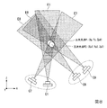
図3及び図4では、第1参照画像の視点C1(Xc1、Yc1、Zc1)、第2近傍画像の視点C7(Xc7、Yc7、Zc7)、及び多視点画像のうち、第1参照画像及び第2近傍画像とは異なる画像の視点C5及びC6を示している。また、第1参照画像における画素について第1処理部103により算出された奥行値に対応する三次元点P(Xp、Yp、Zp)を示している。
Here, the processing performed by the
3 and 4, among the viewpoint C1 (Xc1, Yc1, Zc1) of the first reference image, the viewpoint C7 (Xc7, Yc7, Zc7) of the second neighboring image, and the multi-view image, the first reference image and the first The viewpoints C5 and C6 of an image different from the two neighboring images are shown. Also, a three-dimensional point P (Xp, Yp, Zp) corresponding to a depth value calculated by the
図3に示すように、選択部104は、三次元点Pの位置座標に基づいて、例えば、視差角γn(nは任意の自然数)が所定の角度範囲となる領域に視点を有する画像を、第2近傍画像として選択する。ここでの視差角γnは、視点C1と三次元点Pとを通るベクトル、及び多視点画像の任意の画像における視点Cnと三次元点Pとを通るベクトルの間の角度である。例えば、選択部104は、三次元点Pの位置座標に基づいて、視点C1から三次元点Pの方向を示す視線ベクトルV1を算出する。また、選択部104は、他の多視点画像の視点Cn(nは1以外の任意の自然数)から三次元点Pの方向を示す視線ベクトルVnを算出する。そして、選択部104は、視線ベクトルV1とVnとの間の視差角が所定の角度範囲である場合、視線ベクトルVnに対応する視点Cnを有する画像を第2近傍画像とする。ここで、視線ベクトルVnは「ベクトル群」の一例である。
As illustrated in FIG. 3, based on the position coordinates of the three-dimensional point P, the
或いは、選択部104は、視線ベクトルV1との視差角が所定の角度範囲となる領域を抽出し、抽出した領域の内部に視点がある画像を第2近傍画像とするようにしてもよい。
この例で所定の角度範囲が視差角γ6とγ7とを含み、視差角γ5を含まない範囲に設定された場合、視差角γ7に対応する視点C7から撮像された画像、及び視差角γ6に対応する視点C6から撮像された画像が、第2近傍画像として選択される。このように、選択部104は、複数の画像を第2近傍画像として選択してよい。
Alternatively, the
In this example, when the predetermined angle range includes the parallax angles γ6 and γ7 and is set to a range that does not include the parallax angle γ5, the image captured from the viewpoint C7 corresponding to the parallax angle γ7 and the parallax angle γ6 The image picked up from the viewpoint C <b> 6 is selected as the second neighboring image. Thus, the
また、図4に示すように、選択部104は、三次元点Pの位置座標に基づいて、距離L1に対する距離Ln(nは1以外の任意の自然数)との距離比が所定の距離比の範囲となる領域に視点がある画像を、第2近傍画像として選択するようにしてもよい。ここで、距離L1は視点C1から三次元点Pまでの距離である。また、距離Lnは、多視点画像の任意の画像における視点Cnから三次元点Pまでの距離である。例えば、選択部104は、三次元点Pの位置座標、及び視点Cnの位置座標に基づいて、距離Lnを算出する。そして、選択部104は、距離L1に対する距離Lnの比が所定の距離比の範囲内である場合に、その距離Lnに対応する視点Cnから撮像された画像を第2近傍画像とする。この例で、距離L1、L7、L5、L6の順に、距離が大きくなるとすると、例えば、所定の距離比の範囲が距離L1に対する距離L5の比が含まれ、距離L1に対する距離L6の比は含まれない範囲に設定された場合、距離L7に対応する視点C7から撮像された画像、及び距離L5に対応する視点C5から撮像された画像が、第2近傍画像として選択される。
Further, as shown in FIG. 4, based on the position coordinates of the three-dimensional point P, the
なお、ここでは、選択部104が距離L1に対する距離Lnの比に基づいて第2近傍画像を選択する場合を例示して説明したが、これに限定されない。選択部104は、例えば、距離L1と距離Lnの差分が所定の差分閾値未満である場合に、第2近傍画像を選択してもよい。
Here, the case where the selecting
また、選択部104は、視差角γnが所定の角度範囲内であり、尚且つ、距離L1に対する距離比が所定の距離比の範囲内である視点Cnに対応する画像を第2近傍画像として選択してよい。これにより、選択部104は、視差角が所定の角度範囲内であり、尚且つ距離比が所定の距離比の範囲内である撮像条件を充足する第2近傍画像を選択でき、奥行値を精度よく算出することが可能となる。
Further, the
また、選択部104は、第1処理部103により算出された奥行値ごとに、第2近傍画像を選択してもよい。この場合、選択部104は奥行値に対応する三次元点ごとに、その三次元点を基準とした視差角、及び距離を全ての多視点画像について算出し、その三次元点との視差角が所定の角度範囲内であり、及び/又は距離比が所定の距離比の範囲内である画像を第2近傍画像として選択する。これにより、第1参照画像における画素ごとに、精度よく奥行値を算出することができる第2近傍画像を選択できる。
Further, the
或いは、選択部104は、奥行値を算出した第1参照画像に対して、一つの第2近傍画像を選択してもよい。この場合、選択部104は、第1参照画像において代表とする代表画素、及び代表奥行値を決定する。選択部104は、代表画素及び代表奥行値に対応する三次元点の位置座標に基づいて適切な第2近傍画像を選択し、選択した第2近傍画像を、第1参照画像の第2近傍画像とする。ここで、代表画素は、例えば、第1参照画像における光学中心に対応する画素である。また、代表奥行値は、例えば、第1参照画像において算出された全ての奥行値の中央値である。もっとも、これに限定されることはなく、代表画素は第1参照画像における任意の画素であってよいし、代表奥行値は全ての奥行値の単純加算平均値やその他の統計的な手法を用いて算出される値であってもよいし、任意の画素に対して算出された奥行値であってもよい。
Alternatively, the
図1に戻り、第2処理部105は、第1参照画像、及び選択部104により選択された第2近傍画像を用いて、ステレオマッチングを行うことにより第1参照画像における画素ごとの奥行値を算出する。第2処理部105は、ステレオマッチングの手法として、第1処理部103による手法と同じ手法によりステレオマッチングを行ってもよいし、異なる手法によりステレオマッチングを行ってもよい。第2処理部105は、奥行値を精度よく算出することが可能な撮像条件を充足する第2近傍画像を用いるため、精度の高い奥行値を算出することが可能である。ここで、第2処理部105により算出される奥行値は、「第2奥行値」の一例である。
Returning to FIG. 1, the
ここで、第2処理部105が行う処理について、図5を用いて説明する。図5は、第1の実施形態に係る第2処理部105が行う処理を説明する図である。図5では、視点C1から撮像領域E1が撮像され、視点C7から撮像領域E7が撮像される様子を俯瞰した模式図を示している。また、この例では、第1参照画像における任意の画素pについて、第2処理部105により奥行値zp#が算出され、この画素pに対応する三次元点Pの位置座標が(Xp、Yp、Zp#)であることを示している。また、多視点画像のうち、第1参照画像及び第2近傍画像とは異なる画像の視点C5及びC6を模式的に示している。
Here, the processing performed by the
図5に示すように、第2処理部105は、第1処理部103により奥行値zpが算出された第1参照画像の画素pについて、奥行値を探索する。具体的には、第2処理部105は、画素pの奥行値の候補となり得る候補値の全てに対して、画素pとその近傍の画素と間における相関値を算出し、候補値の中で最も高い相関を示すものを奥行値zp#とする。
As illustrated in FIG. 5, the
ここで、第2処理部105は、奥行値を探索する範囲を、例えば、第1処理部103により算出された奥行値zpを含む所定の範囲とする。具体的には、第2処理部105は、奥行値zp±所定値αに含まれる範囲を、奥行値を探索する範囲とする。この場合の所定値αは、例えば、第1処理部103により算出された奥行値zpに含まれる誤差量に相当する値である。この場合、奥行値の探索の範囲が限定されるため、第2処理部105は探索する奥行の間隔を小さくして詳細に相関値を算出することができる。この場合、第2処理部105により算出される奥行値zp#は、第1処理部103により算出された奥行値zpより精度が高い値となり、画素pに対応する三次元点Pの位置のZ座標(Zp#)を、精度の高い値とすることが可能となる。
Here, the
図1に戻り、出力部106は、第2処理部105により算出された画素ごとの奥行値の各々とカメラパラメータを用いて、多視点画像に撮像されている対象物体における三次元の位置座標を持つ三次元点群に変換して出力する。出力部106により変換された点群を用いることにより、対象物体における三次元形状モデルを生成することが可能である。
画像情報記憶部107は、多視点画像の画像情報及びそのカメラパラメータを記憶する。
Returning to FIG. 1, the
The image
ここで、第1の実施形態に係るステレオマッチング処理装置1が行う動作について図6を用いて説明する。図6は、第1の実施形態に係るステレオマッチング処理装置1が行う動作例を示すフローチャートである。 Here, an operation performed by the stereo matching processing device 1 according to the first embodiment will be described with reference to FIG. FIG. 6 is a flowchart illustrating an operation example performed by the stereo matching processing device 1 according to the first embodiment.
ステップS1:
画像情報取得部101は、多視点画像の画像情報を取得する。画像情報取得部101は、取得した画像情報を画像情報記憶部107に記憶させる。
ステップS2:
カメラパラメータ推定部102は、多視点画像の画像情報に基づいて、カメラパラメータを推定する。カメラパラメータ推定部102は、推定したカメラパラメータを、画像情報に対応付けて画像情報記憶部107に記憶させる。
Step S1:
The image
Step S2:
The camera
ステップS3:
第1処理部103は、多視点画像から任意の第1参照画像を選択する。
ステップS4:
第1処理部103は、多視点画像から第1近傍画像を選択する。第1処理部103は、例えば、多視点画像のうち第1参照画像の視点に近い視点を有する画像を、第1近傍画像として選択する。
ステップS5:
第1処理部103は、第1参照画像及び第1近傍画像を用いてステレオマッチングを行うことにより、第1参照画像における画素ごとの奥行値を算出する。第1処理部103は算出した奥行値(第1奥行値)を選択部104に出力する。
ステップS6:
選択部104は、第1処理部103により算出された奥行値に対応する三次元点に基づいて、第2近傍画像を選択する。選択部104は、例えば、三次元点に対する視差角が所定の視差角の範囲内であり、尚且つ、視点から三次元点までの距離が、第1参照画像の視点C1から三次元点までの距離L1に対して所定の距離比の範囲内である画像を第2近傍画像として選択する。
ステップS7:
第2処理部105は、第1参照画像及び、選択部104により選択された第2近傍画像を用いてステレオマッチングを行うことにより、第1参照画像における画素ごとの奥行値(第2奥行値)を算出する。
ステップS8:
出力部106は、第2処理部105により奥行値が算出された画素を対応する三次元点の位置座標に変換する。
ステップS9:
ステレオマッチング処理装置1は、ステレオマッチングを終了させるか否かを判定する。ステレオマッチング処理装置1は、例えば、所定の終了条件を充足した場合、ステレオマッチングを終了させると判定する。所定の終了条件とは、例えば、全ての多視点画像において奥行値が算出された場合である。ステレオマッチング処理装置1は、ステレオマッチングを終了させないと判定した場合、ステップS3に示す処理に戻り、再び、多視点画像から第1参照画像を選択する処理を行う。
Step S3:
The
Step S4:
The
Step S5:
The
Step S6:
The selecting
Step S7:
The
Step S8:
The
Step S9:
The stereo matching processing device 1 determines whether to end the stereo matching. For example, when a predetermined end condition is satisfied, the stereo matching processing device 1 determines to end the stereo matching. The predetermined end condition is, for example, a case where a depth value has been calculated for all multi-viewpoint images. When determining that the stereo matching is not to be ended, the stereo matching processing device 1 returns to the process illustrated in step S3, and performs the process of again selecting the first reference image from the multi-view image.
以上説明したように、第1の実施形態に係るステレオマッチング処理装置1は、第1処理部103により算出された奥行値(第1奥行値)に基づいて第2近傍画像を選択し、第2処理部105が第2近傍画像を用いて奥行値(第2奥行値)を算出する。これにより、第1の実施形態に係るステレオマッチング処理装置1は、第1処理部103により算出された奥行値に基づいて第2近傍画像を選択することができるため、精度の高い奥行値を算出することができる画像のペアを容易に選択することが可能である。
As described above, the stereo matching processing device 1 according to the first embodiment selects the second neighboring image based on the depth value (first depth value) calculated by the
(第2の実施形態)
次に、第2の実施形態について説明する。以下の説明においては、上述した実施形態と異なる部分についてのみ説明し、同じ部分については同等の符号を付してその説明を省略する。
(Second embodiment)
Next, a second embodiment will be described. In the following description, only portions different from the above-described embodiment will be described, and the same portions will be denoted by the same reference numerals and description thereof will be omitted.
本実施形態においては、カメラパラメータの誤差を低減させるために、複数の画像の奥行値を合成する。図7は、第2の実施形態に係るステレオマッチング処理装置1Aの構成例を示すブロック図である。ステレオマッチング処理装置1Aは、例えば、第3処理部108を備える。
In the present embodiment, depth values of a plurality of images are combined in order to reduce errors in camera parameters. FIG. 7 is a block diagram illustrating a configuration example of a stereo matching processing device 1A according to the second embodiment. The stereo matching processing device 1A includes, for example, a
第3処理部108は、第2参照画像を選択する。第2参照画像は、奥行値を算出する対象とする画像であって、第1参照画像とは異なる画像である。第3処理部108は、例えば、第1参照画像の視点C1の近傍に視点を有する画像を、第2参照画像として選択する。或いは、第3処理部108は、第1処理部103により算出された奥行値に基づいて、第2参照画像を選択するようにしてもよい。この場合、第3処理部108は、第1処理部103により算出された奥行値に対応する三次元点の可視性の判定を行い、当該三次元点が撮像された画像を第2参照画像として選択する。
The
また、第3処理部108は、第3近傍画像を選択する。第3近傍画像は、多視点画像のうち第2参照画像とは異なる画像であって、第2参照画像と組み合わせてステレオマッチング処理が行われる画像である。第3処理部108は、例えば、第1処理部103により第1近傍画像が選択される場合と同様に、第2参照画像と視点が近い画像を第3近傍画像として選択する。或いは、第3処理部108は、選択部104により第2近傍画像が選択される場合と同様に、第2参照画像の視点の位置、及び第1処理部103により算出された奥行値に対応する三次元座標の位置の相対的な位置関係に応じて、視差角γ及び距離Lが適切となる視点を有する画像を第3近傍画像として選択するようにしてよい。
Further, the
第3処理部108は、第2参照画像及び第3近傍画像を用いてステレオマッチングを行うことにより第2参照画像における画素ごとの奥行値を算出する。なお、ステレオマッチングの手法としては、例えば、正規化相互相関法、位相限定相関法等があり、何れのものを用いてもよい。ここで、第3処理部108により算出される奥行値は、「第3奥行値」の一例である。
The
ここで、第2処理部105により算出された奥行値に対応する三次元点と、第3処理部108により算出された奥行値に対応する三次元点とは、実際には同じ物体であっても、同一の位置座標とはならない場合がある。この一因としては、第1参照画像、第1近傍画像、第2近傍画像、第2参照画像及び第3近傍画像の各々に推定されたカメラパラメータに推定誤差が含まれると考えられるためである。
Here, the three-dimensional point corresponding to the depth value calculated by the
そこで、出力部106は、第2処理部105により算出された画素ごとの奥行値に対応する三次元点の位置座標と、第3処理部108により算出された画素ごとの奥行値に対応する三次元点の位置座標とを合成して一つの三次元点の位置座標を生成し、生成した三次元点を出力する。出力部106は、例えば、両方の位置座標の平均値を算出することにより、一つの三次元点の位置座標を生成する。このように、平均値を用いることで、カメラパラメータの誤差が平均化され、三次元点の位置座標が精度よく算出することが可能となる。
Therefore, the
なお、第3処理部108は、複数の第3近傍画像を選択してもよいし、第1処理部103や第2処理部105により既にステレオマッチングに用いられた第1近傍画像や第2近傍画像を、第3近傍画像として選択してもよい。
Note that the
ここで、第2の実施形態の出力部106が行う処理について、図8を用いて説明する。図8は、第2の実施形態に係る出力部106が行う処理を説明する図である。図8では、視点C1から撮像領域E1が撮像され、視点C7から撮像領域E7が撮像され、視点C8から撮像領域E8が撮像され、そして視点C9から撮像領域E9が撮像される様子を俯瞰した模式図を示している。
この例では、視点C1から撮像領域E1が撮像された画像を第1参照画像とし、視点C7から撮像領域E7が撮像された画像を第2近傍画像とし、視点C8から撮像領域E8が撮像された画像を第2参照画像とし、視点C9から撮像領域E9が撮像された画像を第3近傍画像とする。
また、この例では、第2処理部105により第1参照画像における任意の画素の奥行値に対応する三次元点P(Xp、Yp、Zp#)を示している。また、第3処理部108により第2参照画像における任意の画素の奥行値に対応する三次元点P2(Xp2、Yp2、Zp2)を示している。
Here, a process performed by the
In this example, an image in which the imaging region E1 is captured from the viewpoint C1 is a first reference image, an image in which the imaging region E7 is captured from the viewpoint C7 is a second neighboring image, and the imaging region E8 is captured from the viewpoint C8. The image is defined as a second reference image, and the image obtained by capturing the imaging region E9 from the viewpoint C9 is defined as a third neighboring image.
In this example, the
図8に示すように、出力部106は、第2処理部105により算出された画素ごとの奥行値に対応する三次元点Pと、第3処理部108により算出された画素ごとの奥行値に対応する三次元点P2とを合成して一つの三次元点の位置座標とする。
出力部106は、例えば、三次元点Pと三次元点P2とにおけるXY平面上の距離が、所定の距離未満にある場合に、三次元点Pと三次元点P2とを合成する。
出力部106は、三次元点の各座標値について単純加算平均することにより合成して一つの三次元点を生成する。この場合、三次元点P(Xp、Yp、Zp#)と三次元点P2(Xp2、Yp2、Zp2)とを合成した三次元点の位置座標は((Xp+Xp2)/2、(Yp+Yp2)/2、(Zp#+Zp2)/2)となる。或いは、出力部106は、三次元点の各座標値について重みづけを行った上で加算平均することにより合成して一つの三次元点の位置座標を生成するようにしてもよい。
As illustrated in FIG. 8, the
The
The
図9は、第2の実施形態に係るステレオマッチング処理装置1Aが行う動作例を示すフローチャートである。本フローチャートにおけるステップS101〜S107、及びステップS112に示す処理は、図6のフローチャートにおけるステップS1〜S7及びステップS9に示す処理と同様であるため、その説明を省略する。 FIG. 9 is a flowchart illustrating an operation example performed by the stereo matching processing device 1A according to the second embodiment. The processing shown in steps S101 to S107 and step S112 in this flowchart is the same as the processing shown in steps S1 to S7 and step S9 in the flowchart of FIG.
ステップS108:
第3処理部108は、第1処理部103により算出された奥行値(第1奥行値)に基づいて、第2参照画像を選択する。
ステップS109:
第3処理部108は、多視点画像から第2参照画像とは異なる第3近傍画像を選択する。第3処理部108は、例えば、第2参照画像の視点と近い位置に視点を有する画像を第3近傍画像として選択する。
ステップS110:
第3処理部108は、第2参照画像及び第3近傍画像を用いてステレオマッチングを行うことにより、第2参照画像における画素ごとの奥行値(第3奥行値)を算出する。
ステップS111:
出力部106は、複数の三次元点を合成する。出力部106は、第2処理部105により奥行値が算出された画素を、対応する三次元点の位置座標に変換する。出力部106は、第3処理部108により奥行値が算出された画素を、対応する三次元点の位置座標に変換する。そして、第3処理部108は、これらの三次元点を合成して一つの三次元点を生成する。
Step S108:
The
Step S109:
The
Step S110:
The
Step S111:
The
以上説明したように、第2の実施形態に係るステレオマッチング処理装置1Aは、第1参照画像における画素ごとの三次元点と、第2参照画像における画素ごとの三次元点とを合成して一つの三次元点を生成する。このため、一般にカメラパラメータに推定誤差がある場合には三次元点の精度が劣化するが、第2の実施形態に係るステレオマッチング処理装置1Aでは、複数の画像から算出した三次元点を合成することで、カメラパラメータの誤差を低減することが可能である。 As described above, the stereo matching processing device 1A according to the second embodiment combines the three-dimensional point of each pixel in the first reference image and the three-dimensional point of each pixel in the second reference image to generate one Generate three 3D points. For this reason, the accuracy of the three-dimensional points generally deteriorates when there is an estimation error in the camera parameters. However, the stereo matching processing device 1A according to the second embodiment combines the three-dimensional points calculated from a plurality of images. This makes it possible to reduce errors in camera parameters.
(第3の実施形態)
次に、第3の実施形態について説明する。以下の説明においては、上述した実施形態と異なる部分についてのみ説明し、同じ部分については同等の符号を付してその説明を省略する。
(Third embodiment)
Next, a third embodiment will be described. In the following description, only portions different from the above-described embodiment will be described, and the same portions will be denoted by the same reference numerals and description thereof will be omitted.
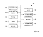
本実施形態では、奥行値を算出することによる処理負荷を軽減させるために、第1処理部103が探索する奥行値の範囲(以下、探索範囲という)を限定する。図10は、第3の実施形態に係るステレオマッチング処理装置1Bの構成例を示すブロック図である。ステレオマッチング処理装置1Bは、例えば、探索範囲決定部109を備える。
In the present embodiment, in order to reduce the processing load caused by calculating the depth value, the range of the depth value searched by the first processing unit 103 (hereinafter, referred to as a search range) is limited. FIG. 10 is a block diagram illustrating a configuration example of a stereo
探索範囲決定部109は、ステレオマッチングを行う画像のカメラパラメータに基づいて、探索範囲を決定する。探索範囲決定部109は、決定した探索範囲を、第1処理部103に出力する。
The search range determining unit 109 determines a search range based on camera parameters of an image on which stereo matching is performed. The search range determination unit 109 outputs the determined search range to the
探索範囲決定部109は、第1処理部103により選択された第1参照画像及び第1近傍画像のカメラパラメータに基づいて、奥行値の範囲(探索範囲)を決定する。探索範囲を限定することにより、奥行値の算出に伴う処理負荷を軽減させることが可能となる。
The search range determination unit 109 determines a depth value range (search range) based on the camera parameters of the first reference image and the first neighboring image selected by the
第1処理部103は、探索範囲決定部109により決定された探索範囲において奥行値を探索する。具体的には、第1処理部103は、第1参照画像における画素pの奥行値を、探索範囲の所定の候補値と仮定し、その仮定した全て候補値におけるマッチングスコアを算出し、算出した仮定した全ての候補値の中で最も高いスコアを示すものを奥行値とする。
The
ステレオマッチングにおいては、原理的に、奥行の探索の刻み幅(間隔)を細かく(小さく)する程、奥行値の精度を高めることが可能である。しかしながら、探索の刻み幅を無限に細かくして、尚且つ、広い探索範囲で探索を行おうとすると計算量が膨大となってしまうため現実的ではない。このため、例えば、探索範囲と探索の刻み幅とをトレードオフの関係として、計算量の上限を超えないようにすることが考えられる。この場合、探索範囲が狭い程、刻み幅を細かく計算することができることから、奥行値の精度を高めることが可能となる。本実施形態では、探索範囲決定部109により探索範囲を限定し、探索の刻み幅が粗くなりすぎないようにすることにより、奥行値を精度よく算出できるようにする。 In stereo matching, in principle, the finer (smaller) the width (interval) of the depth search, the higher the accuracy of the depth value can be. However, it is not realistic to make the search step width infinitely small and to perform a search in a wide search range because the amount of calculation becomes enormous. For this reason, for example, it is conceivable that the search range and the step size of the search are set as a trade-off relationship so as not to exceed the upper limit of the calculation amount. In this case, the narrower the search range, the finer the calculation of the step size, so that the accuracy of the depth value can be increased. In the present embodiment, the search range determination unit 109 limits the search range so that the search step width does not become too coarse, so that the depth value can be accurately calculated.
ここで、探索範囲決定部109が行う処理について、図11を用いて説明する。図11は、第3の実施形態に係る探索範囲決定部109が行う処理を説明する図である。図11では、視点C1から撮像領域E1が撮像され、視点C2から撮像領域E2が撮像される様子を俯瞰した模式図を示している。この例では、視点C1から撮像領域E1が撮像された画像を第1参照画像とし、視点C2から撮像領域E2が撮像された画像を第1近傍画像とする。 Here, the processing performed by the search range determination unit 109 will be described with reference to FIG. FIG. 11 is a diagram illustrating a process performed by the search range determination unit 109 according to the third embodiment. FIG. 11 is a schematic diagram showing a bird's-eye view of a state in which the imaging region E1 is imaged from the viewpoint C1 and the imaging region E2 is imaged from the viewpoint C2. In this example, an image in which the imaging region E1 is imaged from the viewpoint C1 is a first reference image, and an image in which the imaging region E2 is imaged from the viewpoint C2 is a first neighboring image.
図11に示すように、探索範囲決定部109は、例えば、撮像領域E1とE2とが共通する領域である撮像領域E12に基づいて、探索範囲を決定する。具体的に、探索範囲決定部109は、撮像領域E12におけるz軸方向(奥行方向)の最大値Dmax(*、*、zmax)、及び最小値Dmin(*、*、zmin)を算出する。ここで、「*」は任意の座標値を示す。探索範囲決定部109は、算出した「zmin」から「zmax」までの範囲を探索範囲として決定する。つまり、探索範囲決定部109は、第1参照画像と第1近傍画像との両方に撮像されている物体が取り得る奥行値の範囲に探索範囲を決定する。 As illustrated in FIG. 11, the search range determination unit 109 determines a search range based on, for example, an imaging region E12 that is a region where the imaging regions E1 and E2 are common. Specifically, the search range determination unit 109 calculates a maximum value Dmax (*, *, zmax) and a minimum value Dmin (*, *, zmin) in the z-axis direction (depth direction) in the imaging region E12. Here, “*” indicates an arbitrary coordinate value. The search range determination unit 109 determines a range from the calculated “zmin” to “zmax” as a search range. That is, the search range determination unit 109 determines the search range to be within a range of depth values that can be taken by the object imaged in both the first reference image and the first neighboring image.
以上説明したように、第3の実施形態に係るステレオマッチング処理装置1Bは、第1処理部103が探索する探索範囲を限定する探索範囲決定部109を備えるため、奥行値となり得る全ての候補に対して相関値を算出する必要がなくなり、奥行値の算出に伴う処理を軽減させることが可能である。
As described above, since the stereo
(第3の実施形態の変形例1)
次に、第3の実施形態の変形例1について説明する。本変形例では、探索範囲決定部109が第1参照画像の画素の探索範囲に基づいて、第1参照画像の探索範囲を限定する。
本変形例の探索範囲決定部109が行う処理について、図12及び図13を用いて説明する。図12は、第3の実施形態の変形例1に係る探索範囲決定部109が行う処理を説明する図である。図12では、視点C1から撮像領域E1が撮像され、視点C2から撮像領域E2が撮像される様子を俯瞰した模式図を示している。
この例では、視点C1から撮像領域E1が撮像された画像を第1参照画像とし、視点C2から撮像領域E2が撮像された画像を第1近傍画像とする。
(Modification 1 of Third Embodiment)
Next, a first modification of the third embodiment will be described. In this modification, the search range determination unit 109 limits the search range of the first reference image based on the search range of the pixels of the first reference image.
The processing performed by the search range determination unit 109 of the present modification will be described with reference to FIGS. FIG. 12 is a diagram illustrating a process performed by the search range determining unit 109 according to the first modification of the third embodiment. FIG. 12 is a schematic diagram showing a bird's-eye view of a state in which the imaging region E1 is imaged from the viewpoint C1 and the imaging region E2 is imaged from the viewpoint C2.
In this example, an image in which the imaging region E1 is imaged from the viewpoint C1 is a first reference image, and an image in which the imaging region E2 is imaged from the viewpoint C2 is a first neighboring image.
図12に示すように、探索範囲決定部109は、視線ベクトルV1が、撮像領域E2と交差する範囲(以下、交差範囲という)を探索範囲とする。ここで、視線ベクトルV1は、視点C1と、第1参照画像における任意の画素とを通るベクトルである。具体的に、探索範囲決定部109は、交差範囲におけるz軸方向(奥行方向)の最小値Dmin(*、*、zmin)、及び最大値Dmax(*、*、zmax)を算出する。探索範囲決定部109は、算出した最小値Dminから最大値Dmaxまでの間、つまり、「zmin」から「zmax」までの範囲を探索範囲として決定する。 As illustrated in FIG. 12, the search range determination unit 109 sets a range in which the line-of-sight vector V1 intersects the imaging region E2 (hereinafter, referred to as an intersection range) as a search range. Here, the line-of-sight vector V1 is a vector that passes through the viewpoint C1 and an arbitrary pixel in the first reference image. Specifically, the search range determination unit 109 calculates a minimum value Dmin (*, *, zmin) and a maximum value Dmax (*, *, zmax) in the z-axis direction (depth direction) in the intersection range. The search range determination unit 109 determines a range from the calculated minimum value Dmin to the maximum value Dmax, that is, a range from “zmin” to “zmax” as the search range.
或いは、探索範囲決定部109は、最大値Dmaxから最小値Dminまでの間が広すぎて探索範囲の全てについて詳細に相関値を算出することが困難である場合には、最大値Dmaxから最小値Dminまでの間の一部の範囲を探索範囲として決定してもよい。例えば、探索範囲決定部109は、D1(*、*、zave−α)からD2(*、*、zave+β)の間、つまり「zave−α」から「zave+β」までの範囲を探索範囲として決定する。ここで、zaveは探索範囲の平均値、α及びβは正の実数値である。探索範囲決定部109は、ステレオマッチング処理装置1(1A、1B)の計算処理の処理能力や、最大値Dmaxから最小値Dminまでの範囲の大きさ等に応じて、α及びβを任意に決定してよい。 Alternatively, if the range from the maximum value Dmax to the minimum value Dmin is too wide and it is difficult to calculate the correlation values in detail for the entire search range, the search range determination unit 109 sets the minimum value from the maximum value Dmax to the minimum value Dmax. A partial range up to Dmin may be determined as the search range. For example, the search range determining unit 109 determines a search range from D1 (*, *, zave-α) to D2 (*, *, zave + β), that is, a range from “zave-α” to “zave + β”. . Here, zave is the average value of the search range, and α and β are positive real values. The search range determination unit 109 arbitrarily determines α and β according to the processing capability of the calculation processing of the stereo matching processing device 1 (1A, 1B), the size of the range from the maximum value Dmax to the minimum value Dmin, and the like. You may.
探索範囲決定部109は、第1参照画像における全ての画素について、上述した方法により最大値Dmax及び最小値Dminを算出し、探索範囲を決定する。これにより、第1参照画像における画素それぞれに適する探索範囲を決定することができるため、全ての画素について精度よく奥行値を計算することが可能である。 The search range determination unit 109 calculates the maximum value Dmax and the minimum value Dmin for all the pixels in the first reference image by the above-described method, and determines the search range. Accordingly, a search range suitable for each pixel in the first reference image can be determined, so that it is possible to accurately calculate a depth value for all pixels.
上記では、探索範囲決定部109は、第1参照画像における全ての画素について最大値Dmax及び最小値Dminを算出する場合を例示して説明したが、これに限定されない。例えば、探索範囲決定部109は、第1参照画像において選択した特定の画素について最大値Dmax及び最小値Dminを算出するようにしてもよい。 In the above, the search range determination unit 109 has been described as an example in which the maximum value Dmax and the minimum value Dmin are calculated for all the pixels in the first reference image, but the present invention is not limited to this. For example, the search range determination unit 109 may calculate the maximum value Dmax and the minimum value Dmin for a specific pixel selected in the first reference image.
図13は、第3の実施形態の変形例1に係る奥行値を算出する画素の例を示す図である。図13では、第1参照画像を模式的に示している。また、この例では、画像の位置を示す座標系として、uv座標系を示している。このuv座標系においては、第1参照画像における左上の点を原点とし、画像の横方向をu軸、画像の縦方向をv軸として示している。
この場合、図13に示すように、例えば、探索範囲決定部109は、第1参照画像を縦及び横に四分割する直線の交点に対応する画素p10〜p18の各々について、奥行値の最大値Dmaxや最小値Dminをそれぞれ抽出する。例えば、探索範囲決定部109は、抽出した複数の奥行値の平均値、最大値及び最小値に基づいて、画素ごとの探索範囲を決定する。例えば、探索範囲決定部109は、探索範囲の上限を((平均値)+(最大値−最小値)×変数)とし、探索範囲の下限を((平均値)−(最大値−最小値)×変数)とする。ここでの変数は0.5以下の任意の正の実数である。これにより、最小値から最大値までの範囲が広すぎて、全ての範囲で奥行値を算出しようとした場合に、奥行値が精度よく算出できないことがあり得る場合であっても、範囲を狭めることにより奥行値を精度よく算出することが可能となる。
FIG. 13 is a diagram illustrating an example of a pixel for calculating a depth value according to Modification Example 1 of the third embodiment. FIG. 13 schematically shows the first reference image. In this example, a uv coordinate system is shown as a coordinate system indicating the position of an image. In this uv coordinate system, the upper left point in the first reference image is set as the origin, the horizontal direction of the image is set as the u axis, and the vertical direction of the image is set as the v axis.
In this case, as illustrated in FIG. 13, for example, the search range determination unit 109 determines the maximum depth value for each of the pixels p10 to p18 corresponding to the intersections of the straight lines that vertically and horizontally divide the first reference image into four. Dmax and the minimum value Dmin are respectively extracted. For example, the search range determination unit 109 determines a search range for each pixel based on an average value, a maximum value, and a minimum value of the extracted plurality of depth values. For example, the search range determination unit 109 sets the upper limit of the search range to ((average value) + (maximum value−minimum value) × variable) and sets the lower limit of the search range to ((average value) − (maximum value−minimum value)). × variable). The variable here is any positive real number of 0.5 or less. Thereby, even if the range from the minimum value to the maximum value is too wide and the depth value is calculated in the entire range, the depth value may not be calculated with high accuracy, the range is narrowed. This makes it possible to calculate the depth value with high accuracy.
そして、探索範囲決定部109は、画素p10〜p18の各々について算出した画素ごとの探索範囲の上限及び探索範囲の下限値のうち、最大の値を第1参照画像における探索範囲の上限、最小の値を探索範囲の下限とする。或いは、算出した値のうち最大の値及び最小の値の各々に所定のマージンを付加した値を、探索範囲の上限及び下限としてもよい。これにより、探索範囲決定部109は、第1参照画像における全ての画素について探索範囲を決定する場合よりも、探索範囲を算出する処理負荷を軽減させることが可能である。 Then, the search range determination unit 109 sets the maximum value among the upper limit of the search range and the lower limit of the search range for each pixel calculated for each of the pixels p10 to p18 to the upper limit and the minimum of the search range in the first reference image. The value is the lower limit of the search range. Alternatively, a value obtained by adding a predetermined margin to each of the maximum value and the minimum value among the calculated values may be set as the upper limit and the lower limit of the search range. Thereby, the search range determination unit 109 can reduce the processing load for calculating the search range as compared with the case where the search range is determined for all the pixels in the first reference image.
なお、上記では、第1参照画像において9個の点の画素を選択する場合を例示して説明したが、これに限定されることはなく、探索範囲決定部109は、この例示よりも多くの画素を選択してもよいし、この例示よりも少ない個数の画素を選択してもよい。また、探索範囲決定部109は、第1参照画像における任意の位置にある画素を選択してよい。 In the above description, a case where nine pixels in the first reference image are selected has been described as an example. However, the present invention is not limited to this, and the search range determination unit 109 may perform more than this example. Pixels may be selected, or a smaller number of pixels than in this example may be selected. Further, the search range determining unit 109 may select a pixel at an arbitrary position in the first reference image.
以上説明したように、第3の実施形態の変形例1に係るステレオマッチング処理装置1Bは、第1参照画像における画素の方向を示す視線ベクトルV1と、第1近傍画像の撮像領域E2とに基づいて、探索範囲を決定する。これにより、第1参照画像における画素ごとに、探索範囲を決定することができ、精度よく奥行値を算出することが可能となる。また、第1参照画像において選択された画素の探索範囲に基づいて、第1参照画像の全体の探索範囲を決定することができ、処理負荷を増加させることなく、精度よく奥行値を算出することが可能となる。
As described above, the stereo
(第3の実施形態の変形例2)
次に、第3の実施形態の変形例2について説明する。本変形例では、探索範囲決定部109が予め定められた探索範囲の上限に基づいて、探索範囲を限定する。
本変形例の探索範囲決定部109が行う処理について、図14を用いて説明する。図14は、第3の実施形態の変形例2に係る探索範囲決定部109が行う処理を説明する図である。図14では、図12同様に、視点C1から撮像領域E1が撮像され、視点C2から撮像領域E2が撮像される様子を俯瞰した模式図を示している。また、視点C1から撮像領域E1が撮像された画像を第1参照画像とし、視点C2から撮像領域E2が撮像された画像を第1近傍画像とする。
(Modification 2 of Third Embodiment)
Next, a second modification of the third embodiment will be described. In this modification, the search range determination unit 109 limits the search range based on a predetermined upper limit of the search range.
The processing performed by the search range determination unit 109 of the present modification will be described with reference to FIG. FIG. 14 is a diagram illustrating a process performed by the search range determination unit 109 according to the second modification of the third embodiment. FIG. 14 is a schematic diagram showing a bird's-eye view of a state in which the imaging region E1 is imaged from the viewpoint C1 and the imaging region E2 is imaged from the viewpoint C2, as in FIG. Further, an image in which the imaging region E1 is captured from the viewpoint C1 is a first reference image, and an image in which the imaging region E2 is captured from the viewpoint C2 is a first neighboring image.
図14に示すように、探索範囲決定部109は、予め定められた探索範囲の上限である上限値Dmaxth(*、*、zmaxth)を上限として、探索範囲を決定する。
これにより、第3の実施形態の変形例2に係るステレオマッチング処理装置1Bでは、第1参照画像における光学中心に対応する視線ベクトルV1と、第1近傍画像における光学中心に対応する視線ベクトルV2とがほぼ平行となる位置関係である場合、撮像領域E1とE2の共通領域における奥行方向の最大値が無限大となる場合であっても、上限値Dmaxthを上限とすることができる。なお、ここでの上限値Dmaxthは、ステレオマッチング処理装置1(1A、1B)の計算処理の処理能力等に応じて、任意に決定されてよい。
As illustrated in FIG. 14, the search range determination unit 109 determines a search range with an upper limit Dmaxth (*, *, zmaxth) that is a predetermined upper limit of the search range as an upper limit.
Thereby, in the stereo
(第3の実施形態の変形例3)
次に、第3の実施形態の変形例3について説明する。本変形例では、探索範囲決定部109が視差角に基づいて探索範囲を限定する。
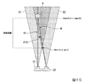
本変形例の探索範囲決定部109が行う処理について、図15を用いて説明する。図15は、第3の実施形態の変形例3に係る探索範囲決定部109が行う処理を説明する図である。図15では、図14同様に、視点C1から撮像領域E1が撮像され、視点C2から撮像領域E2が撮像される様子を俯瞰した模式図を示している。また、この例では、視点C1から撮像領域E1が撮像された画像を第1参照画像とし、視点C2から撮像領域E2が撮像された画像を第1近傍画像とする。
(
Next, a third modification of the third embodiment will be described. In this modification, the search range determination unit 109 limits the search range based on the parallax angle.
The processing performed by the search range determination unit 109 of the present modification will be described with reference to FIG. FIG. 15 is a diagram illustrating a process performed by the search range determining unit 109 according to the third modification of the third embodiment. FIG. 15 is a schematic diagram showing a bird's-eye view of a state in which the imaging region E1 is imaged from the viewpoint C1 and the imaging region E2 is imaged from the viewpoint C2, similarly to FIG. In this example, an image in which the imaging region E1 is captured from the viewpoint C1 is a first reference image, and an image in which the imaging region E2 is captured from the viewpoint C2 is a first neighboring image.
図15に示すように、探索範囲決定部109は、予め定められた視差角の閾値である視差角閾値θthに基づいて、探索範囲を決定する。具体的には、探索範囲決定部109は、第1参照画像の光学中心に対応する視線ベクトルV1(光軸)と、上限値Dmaxthとが交差する点qについて、視線ベクトルV1と、視点C2及び点qを通るベクトルMとの間のなす角度(視差角)が視差角閾値θth未満である場合、探索範囲を「範囲なし」、つまり0(ゼロ)とする。ここで、点qは、「奥行上限点」の一例である。 As illustrated in FIG. 15, the search range determination unit 109 determines a search range based on a parallax angle threshold θth that is a predetermined parallax angle threshold. Specifically, the search range determination unit 109 determines, for a point q at which the line-of-sight vector V1 (optical axis) corresponding to the optical center of the first reference image and the upper limit Dmaxth intersect, the line-of-sight vector V1, the viewpoint C2, When the angle (parallax angle) between the vector and the vector M passing through the point q is smaller than the parallax angle threshold θth, the search range is set to “no range”, that is, 0 (zero). Here, the point q is an example of the “depth upper limit point”.
探索範囲が0(ゼロ)である場合、第1処理部103は奥行値を算出しない。つまり、第1処理部103は奥行値を探索する処理を行わない。なお、ここでの視差角閾値θthは、ステレオマッチング処理装置1(1A、1B)の計算処理の処理能力等に応じて、任意に決定されてよい。
When the search range is 0 (zero), the
これにより、第3の実施形態の変形例3に係るステレオマッチング処理装置1Bでは、奥行値を精度よく算出することが困難となる所定の条件を充足する場合に、奥行値を探索しないようにすることができ、奥行値を探索する処理負荷を軽減させることが可能である。ここで所定の条件とは、予め定めた上限値Dmaxthを定めた場合において、画素の奥行値が上限値Dmaxthの位置にあると仮定した場合、視点C1及びC2に対するその画素の視差角が所定の視差角閾値θth未満である場合である。この場合、視差角が小さすぎるため、奥行値を精度よく算出することが困難である。
Thereby, the stereo
(第3の実施形態の変形例4)
次に、第3の実施形態の変形例4について説明する。本変形例では、探索範囲決定部109がSfMの結果に基づいて探索範囲を限定する。
(Modification 4 of Third Embodiment)
Next, a fourth modification of the third embodiment will be described. In this modification, the search range determination unit 109 limits the search range based on the result of SfM.
本変形例の探索範囲決定部109が行う処理について、図16を用いて説明する。図16は、第3の実施形態の変形例4に係る探索範囲決定部109が行う処理を説明する図である。図16では、視点C1から撮像領域E1が撮像された画像を第1参照画像とし、第1参照画像についてSfMから出力された三次元点の点群を俯瞰した模式図を示している。 The processing performed by the search range determination unit 109 of the present modification will be described with reference to FIG. FIG. 16 is a diagram illustrating a process performed by the search range determination unit 109 according to Modification 4 of the third embodiment. FIG. 16 is a schematic diagram in which an image obtained by imaging the imaging region E1 from the viewpoint C1 is used as a first reference image, and a point cloud of three-dimensional points output from SfM for the first reference image is overlooked.
図16に示すように、探索範囲決定部109は、SfMから出力された三次元点の点群のうち、奥行方向(Z軸方向)において最小となる最小値Dmin(*、*、Zmin)、及びZ軸方向において最大となる最大値Dmax(*、*、Zmax)を算出する。探索範囲決定部109は、算出した最小値Dminから最大値Dmaxまでの間、つまり、「zmin」から「zmax」までの範囲、或いは「zmin」から「zmax」までの範囲に所定のマージンを付与した範囲を探索範囲として決定する。ここでのマージンは、ステレオマッチング処理装置1(1A、1B)の計算処理の処理能力や、最大値Dmaxから最小値Dminまでの範囲の大きさ等に応じて決定してよい。例えば、探索範囲決定部109は、「zmax」のs倍から「zmin」の1/s倍を探索範囲とする。ここで、sは、1以上の任意の実数である。 As illustrated in FIG. 16, the search range determination unit 109 determines the minimum values Dmin (*, *, Zmin) that are minimum in the depth direction (Z-axis direction) among the three-dimensional point group output from SfM. And the maximum value Dmax (*, *, Zmax) that becomes the maximum in the Z-axis direction is calculated. The search range determination unit 109 provides a predetermined margin between the calculated minimum value Dmin and the maximum value Dmax, that is, a range from “zmin” to “zmax” or a range from “zmin” to “zmax”. The determined range is determined as a search range. The margin here may be determined according to the processing capacity of the calculation processing of the stereo matching processing device 1 (1A, 1B), the size of the range from the maximum value Dmax to the minimum value Dmin, and the like. For example, the search range determination unit 109 sets the search range from s times “zmax” to 1 / s times “zmin”. Here, s is one or more arbitrary real numbers.
以上説明したように、第3の実施形態の変形例4に係るステレオマッチング処理装置1Bでは、SfMの結果を用いる。これにより、第3の実施形態の変形例4に係るステレオマッチング処理装置1Bでは、容易に探索範囲を決定することが可能となる。
As described above, the stereo
(第3の実施形態の変形例5)
次に、第3の実施形態の変形例5について説明する。本変形例では、探索範囲決定部109が探索範囲を更新させる。
(Modification 5 of Third Embodiment)
Next, a fifth modification of the third embodiment will be described. In this modification, the search range determination unit 109 updates the search range.
本変形例の探索範囲決定部109が行う処理について、図17を用いて説明する。図17は、第3の実施形態の変形例5に係る探索範囲決定部109が行う処理を説明する図である。図17では、視点C1から撮像された第1参照画像について、ステレオマッチングの結果出力された三次元点の点群を俯瞰した模式図を複数示している。図17の左側には、最初の探索範囲F1でステレオマッチングが行われた結果、出力された三次元点の点群を示している。図17の中央には、更新された探索範囲F2を示している。図17の右側には、最初の探索範囲F1でステレオマッチングが行われた結果、及び更新された探索範囲F2でステレオマッチングが行われた結果、出力された三次元点の点群を示している。 The processing performed by the search range determination unit 109 of the present modification will be described with reference to FIG. FIG. 17 is a diagram illustrating a process performed by the search range determination unit 109 according to the fifth modification of the third embodiment. FIG. 17 shows a plurality of schematic diagrams in which a point group of three-dimensional points output as a result of stereo matching is overlooked for the first reference image captured from the viewpoint C1. The left side of FIG. 17 illustrates a point group of three-dimensional points output as a result of performing the stereo matching in the first search range F1. The center of FIG. 17 shows the updated search range F2. The right side of FIG. 17 shows a point group of three-dimensional points output as a result of performing stereo matching in the first search range F1 and as a result of performing stereo matching in the updated search range F2. .
図17に示すように、探索範囲決定部109は、最初に探索範囲F1を決定する。探索範囲決定部109は、上述した第3の実施形態及びその変形例で説明した何れの方法を用いて最初の探索範囲F1を決定してもよい。この場合、第1処理部103は、探索範囲決定部109により決定された探索範囲F1の範囲で奥行値を算出する。
As shown in FIG. 17, the search range determining unit 109 first determines the search range F1. The search range determination unit 109 may determine the first search range F1 by using any of the methods described in the third embodiment and its modifications. In this case, the
すでに述べたように、ステレオマッチング処理装置1(1A、1B)は、ステレオマッチングを終了させる所定の終了条件を充足するまで、第1処理部103による奥行値の算出を繰り返し行う(図6のステップS9、及び図9のステップS112)。
As described above, the stereo matching processing device 1 (1A, 1B) repeatedly performs the calculation of the depth value by the
2回目以降に第1処理部103による奥行値の算出が行われる場合、探索範囲決定部109は、前回以前に第1処理部103により算出された奥行値に対応する三次元点の点群の位置座標に基づいて、探索範囲を更新する。探索範囲決定部109は、例えば、三次元点の点群の位置座標の最小値から最大値までの範囲に、所定のマージンを付加させた範囲を、更新した探索範囲とする。この場合、探索範囲決定部109は、最初の探索範囲F1よりも、更新した探索範囲F2の方が小さい場合に、探索範囲を更新するようにしてもよい。この場合、探索範囲F2は、「他の探索範囲」の一例である。
When the depth value is calculated by the
以上説明したように、第3の実施形態の変形例5に係るステレオマッチング処理装置1Bでは、探索範囲を更新させる。これにより、第3の実施形態の変形例5に係るステレオマッチング処理装置1Bでは、探索範囲を狭めることにより、奥行値の算出に伴う処理負荷を軽減させたり、算出する奥行値の精度を高めたりすることが可能となる。
As described above, the stereo
上述した実施形態におけるステレオマッチング処理装置1(1A、1B)の全部または一部をコンピュータで実現するようにしてもよい。その場合、この機能を実現するためのプログラムをコンピュータ読み取り可能な記録媒体に記録して、この記録媒体に記録されたプログラムをコンピュータシステムに読み込ませ、実行することによって実現してもよい。なお、ここでいう「コンピュータシステム」とは、OSや周辺機器等のハードウェアを含むものとする。また、「コンピュータ読み取り可能な記録媒体」とは、フレキシブルディスク、光磁気ディスク、ROM、CD−ROM等の可搬媒体、コンピュータシステムに内蔵されるハードディスク等の記憶装置のことをいう。さらに「コンピュータ読み取り可能な記録媒体」とは、インターネット等のネットワークや電話回線等の通信回線を介してプログラムを送信する場合の通信線のように、短時間の間、動的にプログラムを保持するもの、その場合のサーバやクライアントとなるコンピュータシステム内部の揮発性メモリのように、一定時間プログラムを保持しているものも含んでもよい。また上記プログラムは、前述した機能の一部を実現するためのものであってもよく、さらに前述した機能をコンピュータシステムにすでに記録されているプログラムとの組み合わせで実現できるものであってもよく、FPGA等のプログラマブルロジックデバイスを用いて実現されるものであってもよい。 All or part of the stereo matching processing device 1 (1A, 1B) in the above-described embodiment may be realized by a computer. In that case, a program for realizing this function may be recorded on a computer-readable recording medium, and the program recorded on this recording medium may be read and executed by a computer system. Here, the “computer system” includes an OS and hardware such as peripheral devices. The “computer-readable recording medium” refers to a portable medium such as a flexible disk, a magneto-optical disk, a ROM, and a CD-ROM, and a storage device such as a hard disk built in a computer system. Further, a “computer-readable recording medium” refers to a communication line for transmitting a program via a network such as the Internet or a communication line such as a telephone line, which dynamically holds the program for a short time. Such a program may include a program that holds a program for a certain period of time, such as a volatile memory in a computer system serving as a server or a client in that case. The program may be for realizing a part of the functions described above, or may be a program that can realize the functions described above in combination with a program already recorded in a computer system, It may be realized using a programmable logic device such as an FPGA.
以上、この発明の実施形態について図面を参照して詳述してきたが、具体的な構成はこの実施形態に限られるものではなく、この発明の要旨を逸脱しない範囲の設計等も含まれる。 As described above, the embodiments of the present invention have been described in detail with reference to the drawings. However, the specific configuration is not limited to the embodiments, and includes a design and the like within a range not departing from the gist of the present invention.
1、1A、1B…ステレオマッチング処理装置
101…画像情報取得部
102…カメラパラメータ推定部
103…第1処理部
104…選択部
105…第2処理部
106…出力部
107…画像情報記憶部
108…第3処理部
109…探索範囲決定部
1, 1A, 1B ... stereo
Claims (16)
前記複数の画像における第1参照画像と前記第1参照画像とは異なる第1近傍画像とのステレオマッチングを行うことにより、前記第1参照画像における画素ごとの奥行値である第1奥行値を算出する第1処理部と、
前記第1奥行値に基づいて、前記複数の画像における前記第1参照画像とは異なる第2近傍画像を選択する選択部と、
前記第1参照画像と前記第2近傍画像とのステレオマッチングを行うことにより前記第1参照画像における画素ごとの奥行値である第2奥行値を算出する第2処理部
を備えることを特徴とするステレオマッチング処理装置。 A stereo matching processing device that calculates a depth value of the target object using a plurality of images of the target object captured from different imaging positions,
Calculating a first depth value that is a depth value for each pixel in the first reference image by performing stereo matching between a first reference image in the plurality of images and a first neighboring image different from the first reference image. A first processing unit,
A selection unit that selects a second neighboring image different from the first reference image in the plurality of images based on the first depth value;
A second processing unit that calculates a second depth value that is a depth value for each pixel in the first reference image by performing stereo matching between the first reference image and the second neighborhood image. Stereo matching processing device.
を更に備え、
前記第1処理部は、前記探索範囲決定部により決定された前記探索範囲の範囲で第1奥行値を算出する
ことを特徴とする請求項1に記載のステレオマッチング処理装置。 A search range determining unit that determines a search range in which the first depth value is searched, based on an imaging position and an imaging direction in each of the camera parameters of the first reference image and the first neighboring image,
The stereo matching processing device according to claim 1, wherein the first processing unit calculates a first depth value within a range of the search range determined by the search range determination unit.
ことを特徴とする請求項2に記載のステレオマッチング処理装置。 The said search range determination part determines the said search range based on the range where the imaging area of the said 1st reference image and the imaging area of the said 1st vicinity image are common. Stereo matching processing device.
ことを特徴とする請求項2に記載のステレオマッチング処理装置。 The search range determination unit is configured to determine the search range based on a region where an imaging position of the first reference image and a line of sight passing through any pixel in the first reference image intersect with an imaging region of the first neighboring image. The stereo matching processing device according to claim 2, wherein:
ことを特徴とする請求項2に記載のステレオマッチング処理装置。 The search range determination unit is configured to determine the search range based on a depth value of a pixel of the first reference image corresponding to a three-dimensional point group obtained by inputting the plurality of images to SfM (Structure from Motion). The stereo matching processing device according to claim 2, wherein:
ことを特徴とする請求項2に記載のステレオマッチング処理装置。 The search range determination unit is configured to perform another search determined based on the first depth value calculated by the first processing unit when a part of an imaging region of the first reference image is set as the search range. The stereo matching processing device according to claim 2, wherein when the range is smaller than the search range, the other search range is updated as the search range.
ことを特徴とする請求項2に記載のステレオマッチング処理装置。 The search range determination unit is configured to include: an imaging position of the first reference image; a line-of-sight vector that passes through a depth upper limit at which a depth value is a predetermined upper limit in an imaging region of the first reference image; When the parallax angle between the imaging position and the gaze vector passing through the position corresponding to the depth upper limit point in the imaging region of the first neighboring image is less than a predetermined parallax angle threshold, the search range is set to no range. The stereo matching processing device according to claim 2, wherein:
請求項1から請求項7の何れか一項に記載のステレオマッチング処理装置。 The selecting unit may include, among a vector group passing through the three-dimensional point corresponding to the first depth value and the imaging position of each of the plurality of images, an angle between the vector and the vector passing through the imaging position of the first reference image. The stereo matching processing device according to any one of claims 1 to 7, wherein an image captured at an imaging position corresponding to a vector within a predetermined range is selected as the second neighboring image.
請求項1から請求項8の何れか一項に記載のステレオマッチング処理装置。 The selecting unit is configured to determine a distance from a three-dimensional point corresponding to the first depth value to an imaging position of the first reference image and a distance from the three-dimensional point to an imaging position of each of the plurality of images. The stereo matching processing device according to any one of claims 1 to 8, wherein the second neighboring image is selected.
請求項1から請求項9の何れか一項に記載のステレオマッチング処理装置。 The stereo matching processing device according to claim 1, wherein the selection unit selects the second neighboring image for each pixel in a first reference image.
請求項1から請求項9の何れか一項に記載のステレオマッチング処理装置。 The stereo matching processing device according to any one of claims 1 to 9, wherein the selection unit selects the second neighboring image for each first reference image.
請求項11に記載のステレオマッチング処理装置。 The stereo matching processing device according to claim 11, wherein the selection unit selects the second neighboring image based on a predetermined representative pixel and a predetermined representative depth value in the first reference image.
請求項12に記載のステレオマッチング処理装置。 The selecting unit, the representative pixel as a pixel corresponding to the optical center in the first reference image, the representative depth value as a median of the plurality of first depth values calculated in the first reference image, The stereo matching processing device according to claim 12, wherein the second neighborhood image is selected.
を更に備えることを特徴とする請求項1から請求項13の何れか一項に記載のステレオマッチング処理装置。 By performing stereo matching using a second reference image different from the first reference image among the plurality of images and a third neighboring image different from the second reference image included in the plurality of images, The stereo matching processing device according to any one of claims 1 to 13, further comprising: a third processing unit that calculates a third depth value that is a depth value for each pixel in the two reference images.
第1処理部が、前記複数の画像における第1参照画像と前記第1参照画像とは異なる第1近傍画像とのステレオマッチングを行うことにより、前記第1参照画像における画素ごとの奥行値である第1奥行値を算出する第1処理工程と、
選択部が、前記第1奥行値に基づいて、前記複数の画像における前記第1参照画像とは異なる第2近傍画像を選択する選択工程と、
第2処理部が、前記第1参照画像と前記第2近傍画像とのステレオマッチングを行うことにより前記第1参照画像における画素ごとの奥行値である第2奥行値を算出する第2処理工程
を含むことを特徴とするステレオマッチング処理方法。 A stereo matching processing method for calculating a depth value of the target object using a plurality of images of the target object captured from different imaging positions,
The first processing unit performs stereo matching between a first reference image in the plurality of images and a first neighboring image different from the first reference image to obtain a depth value for each pixel in the first reference image. A first processing step of calculating a first depth value;
A selecting unit that selects a second neighboring image different from the first reference image in the plurality of images based on the first depth value;
A second processing step in which the second processing unit calculates a second depth value that is a depth value for each pixel in the first reference image by performing stereo matching between the first reference image and the second neighboring image. A stereo matching processing method comprising:
前記コンピュータを、
前記複数の画像における第1参照画像と前記第1参照画像とは異なる第1近傍画像とのステレオマッチングを行うことにより、前記第1参照画像における画素ごとの奥行値である第1奥行値を算出する第1処理手段と、
前記第1奥行値に基づいて、前記複数の画像における前記第1参照画像とは異なる第2近傍画像を選択する選択手段と、
前記第1参照画像と前記第2近傍画像とのステレオマッチングを行うことにより前記第1参照画像における画素ごとの奥行値である第2奥行値を算出する第2処理手段
として動作させるためのプログラム。 A program that operates a computer as a stereo matching processing device that calculates a depth value of the target object using a plurality of images of the target object captured from different imaging positions,
Said computer,
Calculating a first depth value that is a depth value for each pixel in the first reference image by performing stereo matching between a first reference image in the plurality of images and a first neighboring image different from the first reference image. First processing means for performing
Selecting means for selecting a second neighboring image different from the first reference image in the plurality of images based on the first depth value;
A program for operating as a second processing unit that calculates a second depth value that is a depth value for each pixel in the first reference image by performing stereo matching between the first reference image and the second neighboring image.
Priority Applications (1)
| Application Number | Priority Date | Filing Date | Title |
|---|---|---|---|
| JP2018119162A JP2019220099A (en) | 2018-06-22 | 2018-06-22 | Stereo matching processing device, stereo matching processing method, and program |
Applications Claiming Priority (1)
| Application Number | Priority Date | Filing Date | Title |
|---|---|---|---|
| JP2018119162A JP2019220099A (en) | 2018-06-22 | 2018-06-22 | Stereo matching processing device, stereo matching processing method, and program |
Publications (1)
| Publication Number | Publication Date |
|---|---|
| JP2019220099A true JP2019220099A (en) | 2019-12-26 |
Family
ID=69096695
Family Applications (1)
| Application Number | Title | Priority Date | Filing Date |
|---|---|---|---|
| JP2018119162A Pending JP2019220099A (en) | 2018-06-22 | 2018-06-22 | Stereo matching processing device, stereo matching processing method, and program |
Country Status (1)
| Country | Link |
|---|---|
| JP (1) | JP2019220099A (en) |
Cited By (4)
| Publication number | Priority date | Publication date | Assignee | Title |
|---|---|---|---|---|
| WO2023095375A1 (en) * | 2021-11-29 | 2023-06-01 | パナソニックIpマネジメント株式会社 | Three-dimensional model generation method and three-dimensional model generation device |
| CN117456114A (en) * | 2023-12-26 | 2024-01-26 | 北京智汇云舟科技有限公司 | Multi-view-based three-dimensional image reconstruction method and system |
| CN117576180A (en) * | 2024-01-15 | 2024-02-20 | 常熟理工学院 | Multi-view depth estimation method and application based on self-adaptive multi-scale window |
| JP7451465B2 (en) | 2021-07-29 | 2024-03-18 | 株式会社東芝 | Learning method, program and image processing device |
Citations (6)
| Publication number | Priority date | Publication date | Assignee | Title |
|---|---|---|---|---|
| WO2014141522A1 (en) * | 2013-03-12 | 2014-09-18 | 富士フイルム株式会社 | Image assessment device, capturing device, 3d measuring device, image assessment method, and program |
| JP2016524125A (en) * | 2013-03-15 | 2016-08-12 | ペリカン イメージング コーポレイション | System and method for stereoscopic imaging using a camera array |
| JP2016217944A (en) * | 2015-05-22 | 2016-12-22 | シャープ株式会社 | Measurement device and measurement method |
| JP2017054481A (en) * | 2015-07-02 | 2017-03-16 | 株式会社リコー | Parallax image creation device, parallax image creation method, parallax image creation program, object recognition device, and instrument control system |
| US20170154219A1 (en) * | 2014-06-17 | 2017-06-01 | Yujin Robot Co., Ltd. | Apparatus of recognizing position of mobile robot using direct tracking and method thereof |
| JP2018057532A (en) * | 2016-10-04 | 2018-04-12 | 凸版印刷株式会社 | Prosthetic wearing unit shape acquisition method and prosthetic wearing unit shape acquisition system |
-
2018
- 2018-06-22 JP JP2018119162A patent/JP2019220099A/en active Pending
Patent Citations (6)
| Publication number | Priority date | Publication date | Assignee | Title |
|---|---|---|---|---|
| WO2014141522A1 (en) * | 2013-03-12 | 2014-09-18 | 富士フイルム株式会社 | Image assessment device, capturing device, 3d measuring device, image assessment method, and program |
| JP2016524125A (en) * | 2013-03-15 | 2016-08-12 | ペリカン イメージング コーポレイション | System and method for stereoscopic imaging using a camera array |
| US20170154219A1 (en) * | 2014-06-17 | 2017-06-01 | Yujin Robot Co., Ltd. | Apparatus of recognizing position of mobile robot using direct tracking and method thereof |
| JP2016217944A (en) * | 2015-05-22 | 2016-12-22 | シャープ株式会社 | Measurement device and measurement method |
| JP2017054481A (en) * | 2015-07-02 | 2017-03-16 | 株式会社リコー | Parallax image creation device, parallax image creation method, parallax image creation program, object recognition device, and instrument control system |
| JP2018057532A (en) * | 2016-10-04 | 2018-04-12 | 凸版印刷株式会社 | Prosthetic wearing unit shape acquisition method and prosthetic wearing unit shape acquisition system |
Non-Patent Citations (1)
| Title |
|---|
| 吉田 武史 ほか: "Epipolar Transferを利用した対応点探索と回転型ステレオカメラによる密な三次元再構成", 日本ロボット学会誌, vol. 第31巻 第10号(通巻238号), JPN6022016123, 15 December 2013 (2013-12-15), JP, pages 75 - 83, ISSN: 0004759671 * |
Cited By (6)
| Publication number | Priority date | Publication date | Assignee | Title |
|---|---|---|---|---|
| JP7451465B2 (en) | 2021-07-29 | 2024-03-18 | 株式会社東芝 | Learning method, program and image processing device |
| WO2023095375A1 (en) * | 2021-11-29 | 2023-06-01 | パナソニックIpマネジメント株式会社 | Three-dimensional model generation method and three-dimensional model generation device |
| CN117456114A (en) * | 2023-12-26 | 2024-01-26 | 北京智汇云舟科技有限公司 | Multi-view-based three-dimensional image reconstruction method and system |
| CN117456114B (en) * | 2023-12-26 | 2024-04-30 | 北京智汇云舟科技有限公司 | Multi-view-based three-dimensional image reconstruction method and system |
| CN117576180A (en) * | 2024-01-15 | 2024-02-20 | 常熟理工学院 | Multi-view depth estimation method and application based on self-adaptive multi-scale window |
| CN117576180B (en) * | 2024-01-15 | 2024-03-26 | 常熟理工学院 | Multi-view depth estimation method and application based on self-adaptive multi-scale window |
Similar Documents
| Publication | Publication Date | Title |
|---|---|---|
| JP2019220099A (en) | Stereo matching processing device, stereo matching processing method, and program | |
| US8199977B2 (en) | System and method for extraction of features from a 3-D point cloud | |
| JP4392507B2 (en) | 3D surface generation method | |
| JP5955028B2 (en) | Image processing apparatus, image processing method, and image processing program | |
| CN106228605A (en) | A kind of Stereo matching three-dimensional rebuilding method based on dynamic programming | |
| KR101681095B1 (en) | Apparatus and method for generating depth image that have same viewpoint and same resolution with color image | |
| CN105336005B (en) | A kind of method, apparatus and terminal obtaining target object sign data | |
| KR102407137B1 (en) | Method and apparatus for image processing | |
| CN112712596B (en) | Dense matching point cloud building structured model fine reconstruction method | |
| KR101926953B1 (en) | Matching method of feature points in planar array of four - camera group and measurement method based theron | |
| JP4701848B2 (en) | Image matching apparatus, image matching method, and image matching program | |
| US11803982B2 (en) | Image processing device and three-dimensional measuring system | |
| JP2010079505A (en) | Image generating apparatus and program | |
| CN105701787B (en) | Depth map fusion method based on confidence level | |
| Shivakumar et al. | Real time dense depth estimation by fusing stereo with sparse depth measurements | |
| Gadasin et al. | Reconstruction of a Three-Dimensional Scene from its Projections in Computer Vision Systems | |
| US11348271B2 (en) | Image processing device and three-dimensional measuring system | |
| TWI528783B (en) | Methods and systems for generating depth images and related computer products | |
| CN113052880B (en) | SFM sparse reconstruction method, system and application | |
| JP4424797B2 (en) | 3D shape detection method | |
| JP6388806B2 (en) | Projection image generation apparatus, projection image generation program, and projection image generation method | |
| JP2019120590A (en) | Parallax value calculation device, parallax value calculation method and program | |
| JP2802034B2 (en) | 3D object measurement method | |
| Kyöstilä et al. | Merging overlapping depth maps into a nonredundant point cloud | |
| Zhang et al. | Passive 3D reconstruction based on binocular vision |
Legal Events
| Date | Code | Title | Description |
|---|---|---|---|
| A621 | Written request for application examination |
Free format text: JAPANESE INTERMEDIATE CODE: A621 Effective date: 20210519 |
|
| A977 | Report on retrieval |
Free format text: JAPANESE INTERMEDIATE CODE: A971007 Effective date: 20220406 |
|
| A131 | Notification of reasons for refusal |
Free format text: JAPANESE INTERMEDIATE CODE: A131 Effective date: 20220426 |
|
| A521 | Request for written amendment filed |
Free format text: JAPANESE INTERMEDIATE CODE: A523 Effective date: 20220621 |
|
| A02 | Decision of refusal |
Free format text: JAPANESE INTERMEDIATE CODE: A02 Effective date: 20221011 |